H35-10 Direct Vent Gas Fireplace Owners & Installation Manual
60
H35-10 Direct Vent Gas Fireplace Owners & Installation Manual FPI FIREPLACE PRODUCTS INTERNATIONAL LTD. 6988 Venture St., Delta, BC Canada, V4G 1H4 919-486f 11.09.18 Tested by: Installer: Please complete the details on the back cover and leave this manual with the homeowner. Homeowner: Please keep these instructions for future reference. - Do not store or use gasoline or other flammable vapors and liquids in the vicinity of this or any other appliance. - WHAT TO DO IF YOU SMELL GAS • Do not try to light any appliance. • Do not touch any electrical switch: do not use any phone in your building. Leave the building immediately. • Immediately call your gas supplier from a neighbour's phone. Follow the gas supplier's instructions. • If you cannot reach your gas supplier, call the fire department. Installation and service must be performed by a qualified installer, service agency or the gas supplier. WARNING FIRE OR EXPLOSION HAZARD Failure to follow safety warnings exactly could result in serious injury, death, or property damage. H35 Product Video www.hampton-fire.com MODELS: H35-NG10 Natural Gas H35-LP10 Propane
Transcript of H35-10 Direct Vent Gas Fireplace Owners & Installation Manual

H35-10 Direct Vent Gas Fireplace Owners & Installation Manual
FPI FIREPLACE PRODUCTS INTERNATIONAL LTD. 6988 Venture St., Delta, BC Canada, V4G 1H4919-486f 11.09.18
Tested by:
Installer: Please complete the details on the back cover and leave this manual with the homeowner.Homeowner: Please keep these instructions for future reference.
- Do not store or use gasoline or other flammable vapors and liquids in the vicinity of this or any other appliance.
- WHAT TO DO IF YOU SMELL GAS • Do not try to light any appliance. • Do not touch any electrical switch: do not use any phone in your building. Leave the building immediately. • Immediately call your gas supplier from a neighbour's phone. Follow the gas supplier's
instructions. • If you cannot reach your gas supplier, call the fire department. Installation and service must be performed by a qualified installer, service agency or the gas supplier.
WARNINGFIRE OR EXPLOSION HAZARDFailure to follow safety warnings exactly could result in seriousinjury, death, or property damage.
H35 Product Video
www.hampton-fire.comMODELS: H35-NG10 Natural Gas H35-LP10 Propane

2 | Hampton® H35-10 Direct Vent Freestanding Gas Stove
| 2
HAMPTON®
Direct Vent Freestanding Gas StoveTo the New Owner:
Congratulations! You are the owner of a state-of-the-art Hampton® Gas Stove by REGENCY FIREPLACE PRODUCTS . The H35-10 is a hand crafted appliance and has been designed to provide you with all the warmth and charm of a wood fireplace at the flick of a switch. The model H35-10 has been approved by Warnock Hersey/ Intertek for both safety and efficiency. As it also bears our own mark, it promises to provide you with economy, comfort and security for many trouble free years to follow. Please take a moment now to acquaint yourself with these instructions and the many features of your Hampton® Stove.
H35 Product Video

Hampton® H35-10 Direct Vent Freestanding Gas Stove | 3
3| dimensions
ALL PICTURES / DIAGRAMS SHOWN THROUGHOUT THIS MANUAL ARE FOR ILLUSTRATION PURPOSES ONLY.ACTUAL PRODUCT MAY VARY DUE TO PRODUCT ENHANCEMENTS.
UNIT DIMENSIONS WITH VERTICAL VENT COLLAR
21-3/16" (538mm)
16
-1/4
" (4
13
mm
)
22
-7/8
" (5
81
mm
)
26-7/16" (672 mm)
28
-1/8
" (7
14
mm
)
16-3/4" (425mm)
6-1
/4"
(15
9m
m)
1-11/16" (42mm)
29
-5/1
6"
(74
4m
m)
15-3/8" (391mm)
24-7/16" (620mm)
27-3/8" (694mm)

4 | Hampton® H35-10 Direct Vent Freestanding Gas Stove
| 4 dimensions
UNIT DIMENSIONS WITH HORIZONTAL VENT COLLAR
16-3/4" (425mm)
26-7/16" (672 mm)
28-1
/8"
(714 m
m)
15-3/8" (391mm)
25-3
/8"
(645m
m)
27-3/8" (694mm)
22-7
/8"
(581m
m)

Hampton® H35-10 Direct Vent Freestanding Gas Stove | 5
5| table of contents
DIMENSIONS
Unit Dimensions with vertical vent collar .......................3Unit Dimensions with horizontal vent collar ...................4
SAFETY LABEL
Copy of Safety Label .....................................................6
REQUIREMENTS
MA Code - CO Detector ................................................7
INSTALLATION
Important Message SAVE THESE INSTRUCTIONS ....8Specifications ................................................................8Information for Mobile / Manufactured Homes After First Sale ...............................................................8Before You Start .............................................................8General Safety Information ............................................9Installation Checklist ......................................................9Locating Your Gas Stove..............................................10Manufactured Mobile Home Additional Requirements 10Combustion and Ventilation Air ....................................10Accent light bulb install ................................................10Clearances to Combustibles ........................................10OPTIONAL FAN INSTALLATION .................................11Rotating 45o Elbow for Straight Horizontal Terminations ................................................................12Screen removal ...........................................................12Front cast removal ......................................................13Venting Introduction .....................................................14Installation Precautions ...............................................14Safety Precautions for The Installer .............................14Vent Restrictor Position ...............................................14Exterior Vent Terminal Locations .................................154” x 6-5/8” Rigid Pipe ..................................................16Cross Reference Chart only ........................................16Rigid Pipe Venting Systems .........................................18Venting Arrangements .................................................19Venting Arrangements ................................................20Vertical Termination With Co-linear Flex System .........23DV Stove Horizontal Termination Vent Kit ....................24Dura-Vent Termination Kit ............................................26Horizontal Installations ................................................27Rigid Vent system ........................................................27Vertical Termination .....................................................28Rigid Vent system ........................................................28Converting Class-A Metal Chimney to Direct Vent System ................................................................30
Cathedral Ceilings .......................................................31High Elevation ..............................................................31Gas Connection ...........................................................31Aeration Adjustment ....................................................32Gas Pipe Pressure Testing ..........................................32885 S.I.T. Valve Description .........................................32Conversion Kit #743-969 from NG to LP .....................33Back up Battery Install ................................................34Optional Brick Panel ....................................................34Log Set Installation ......................................................35Wall Thermostat ..........................................................36Remote/Receiver coding .............................................36Manual operation(no remote) ......................................36Final Check ..................................................................36Wiring Diagram without thermostat .............................37Wiring Diagram with thermostat ..................................38
OPERATING INSTRUCTIONS
Operating Instructions .................................................39First Fire ......................................................................39Lighting Procedure ......................................................40Shutdown Procedure ...................................................40Copy of the Lighting Plate Instructions .......................41Proflame II Remote Control Operating Instructions 42-45
MAINTENANCE
Normal Operating Sounds of Gas Appliances ...........................................................46Maintenance Instructions ............................................46General Vent Maintenance ..........................................47Log Replacement ........................................................47Glass Replacement .....................................................47Fan Maintenance .........................................................47Accent light bulb replacement .....................................48Safety screen replacement ..........................................48Removing Valve ...........................................................49Installing Valve Assembly ............................................49
PARTS
Main Assembly ............................................................50Burner & Log Assembly ...............................................51
WARRANTY
Warranty ......................................................................52
6 | Hampton® H35-10 Direct Vent Freestanding Gas Stove
| 6 safety decalThis is a copy of the label that accompanies each Direct Vent Freestanding Gas Stove. We have printed a copy of the contents here for your review. NOTE: Hampton® units are constantly being improved. Check the label on the unit and if there is a difference, the label on the unit is the correct one.
COPY OF SAFETY LABEL
For the State of Massachusetts, installation and repair must be done by a plumber or gasfitter licensed in the Commonwealth of Massachusetts.
For the State of Massachusetts, flexible connectors shall not exceed 36 inches in length.
For the State of Massachusetts, the appliances individual manual shut-off must be a t-handle type valve.
The State of Massachusetts requires the installation of a carbon monoxide alarm in accordance with NFPA 720 and a CO alarm with battery back up in the same room where the gas appliance is installed.
Listed: VENTED GAS FIREPLACE HEATER / FOYER AU GAZ À ÉVACUATIONCertified for/Certifiée pour : CANADA and U.S.A.Tested to: CAN/CGA-2.17-M91(R2009)Conforms to: ANSI Z21.88-2014Certified to:CSA 2.33-2014MAY BE INSTALLED IN MANUFACTURED (MOBILE) HOMES AFTER FIRST SALE
DO NOT REMOVE THIS LABEL / NE PAS ENLEVER CETTE ÉTIQUETTE
Minimum supply pressureManifold pressure HighManifold pressure LowOrifice SizeMaximum InputMinimum InputAltitude
Minimum supply pressureManifold pressure HighManifold pressure LowOrifice SizeMaximum InputMinimum InputAltitude
5" WC/C.E. (1.25 kPa)3.5" WC/C.E. (0.87 kPa)1.6" WC/C.E. (0.40 kPa) #37 DMS30,000 Btu/h (8.78 Kw/h)21,500 Btu/h (6.30 Kw/h)0-4500 ft/pi (0-1372m)
Pression d'alimentation minimalePression manifold élevéePression manifold basseTaille de l’orificeDébit calorifique maximalDébit calorifique minimalAltitude
Pression d'alimentation minimalePression manifold élevéePression manifold basseTaille de l’orificeDébit calorifique maximalDébit calorifique minimalAltitude
FACTORY EQUIPPED FOR NATURAL GAS Model:H35-NG10
FACTORY EQUIPPED FOR PROPANE GAS Model:H35-LP1011" WC/C.E. (2.74 kPa)10" WC/C.E. (2.49 kPa)6.4" WC/C.E. (1.59 kPa)#52 DMS29,500 Btu/h (8.64 Kw/h)24,000 Btu/h (7.03 Kw/h)0-4500 ft/pi (0-1372m)
This appliance must be installed in accordance with local codes, if any; if none, follow the National Fuel Gas Code, ANSI Z223.1, or Natural Gas and Propane Installation Code, CSA B149.1.This appliance must be installed in accordance with the Standard CAN/CSA Z240 MH, Mobile Housing, in Canada, or with the Manufactured Home Construction and Safety Standard, Title 24 CFR, Part 3280, in the United States, or when such a standard is not applicable, ANSI/NCS-BCS A225.1/NFPA 501A, Manufactured Home Installations Standard or ANSI A119.2 ou NFPA 501C Standard for Recreational VehiclesThis appliance is only for use with the type of gas indicated on the rating plate and may be installed in an aftermarket, permanently located, manufactured (mobile) home where not prohibited by local codes. See owner's manual for details.Installer l'appareil selon les codes ou règlements locaux, ou, en l'absence de tels règlements, selon les codes d'installation ANSI Z223.1, Na-tional Fuel Gas Code ou CSA-B149.1 en vigueur.Installer l'appareil selon la norme CAN/CSA-Z240, Série MM, Maison mobiles ou CAN/CSA-Z240 VC, Véhicules de camping, ou la norme 24 CFR Part 3280, Manufactured Home Construction and Safety Standard. Si ces normes ne sont pas pertinentes, se référer à la norme ANSI/NCSBCS A225.1/NFPA 501A, Manufactured Home Installations Standard, ou ANSI A119.2 ou NFPA 501C Standard for Recreational Vehicles.Cet appareil doit être utilisé uniquement avec le type de gaz indiqué sur la plaque signalétique. Cet appareil peut être installé dans une maison préfabriquée ou mobile (É.-U. seulement) installée à demeure si les règlements locaux le permettent. Voir le guide d'utilisation pour plus de renseignements. Cet appareil ne peut pas être utilisé avec d'autres gaz sauf si une trousse de conversion certifiée est fournie. This vented gas fireplace heater is not for use with air filters. Ne pas utiliser de filtre à air avec ce foyer au gaz à évacuation.For use with Fan Kit # 743-917 À utiliser avec la trousse du ventilateur no743-917 For use with glass doors certified with the appliance only. À utiliser uniquement avec les portes vitrées certifiées avec l'appareilELECTRICAL SUPPLY/ALIMENTATION ÉLECTRIQUE : 115V_60HZ less than/moins de 2 AMPFor Use Only with Barrier (Part # 743-100) Follow installation instructions. Utiliser uniquement avec un écran de sécurité (pièce n° 743-100) Suivre les consignes d’installation.NOT FOR USE WITH SOLID FUELS. / NE PAS UTILISER AVEC UN COMBUSTIBLE SOLIDEFPI Fireplace Products International Ltd. Delta, BC, Canada Made in Canada/Fabriqué au Canada 919-487a
Minimum Clearances to Combustibles/Dégagements minimaux par rapport aux matériaux combustiblesMinimum ceiling height from top of unit:36”/914mmHteur min. de plafond depuis le dessus de l’appareil : 36”/914mm
A 6-1/2”/165mmB 6”/152mm
Minimum clearance of Vent Terminal to Outside Corner & Inside Corner: with AstroCap 6"/150mm with Dura-Vent Cap 12"/300mm
C 2" / 50mmE 2"/50mm
Serial No./ No de série
E
E
A
A
Left Side Wall
Right Side Wall
VerticalPipe
A
A
BC
Left Side Wall
Right Side Wall
HorizontalPipe
Model/Modele: H35-NG10
Model/Modele: H35-LP10
355
355
APPAREIL FONCTIONNANT AU GAZ NATUREL
APPAREIL FONCTIONNANT AU GAZ PROPANE
DUPLICATE SERIAL NO.
Part #: 919-487a
Colour: Everything black on grey except for items indicated in red.Size: Printed at 100% (H 8.767” x w 6.25”)Material: 2 ml silver matt polyester (DPM SMS)Apr. 8/15: Rev. A–Updated Data
*Printer: Continue number sequence from 918-840 - do not restart at 0
4001172

Hampton® H35-10 Direct Vent Freestanding Gas Stove | 7
7| requirements
5.08: Modifications to NFPA-54, Chapter 10
(2) Revise 10.8.3 by adding the following additional requirements:
(a) For all side wall horizontally vented gas fueled equipment installed in every dwelling, building or structure used in whole or in part for residential purposes, including those owned or operated by the Commonwealth and where the side wall exhaust vent termination is less than seven (7) feet above finished grade in the area of the venting, including but not limited to decks and porches, the following requirements shall be satisfied:
1. INSTALLATION OF CARBON MONOXIDE DETECTORS. At the time of installation of the side wall horizontal vented gas fueled equipment, the installing plumber or gasfitter shall observe that a hard wired carbon monoxide detector with an alarm and battery back-up is installed on the floor level where the gas equipment is to be installed. In addition, the installing plumber or gasfitter shall observe that a battery operated or hard wired carbon monoxide detector with an alarm is installed on each additional level of the dwelling, building or structure served by the side wall horizontal vented gas fueled equipment. It shall be the responsibility of the property owner to secure the services of qualified licensed professionals for the installation of hard wired carbon monoxide detectors
a. In the event that the side wall horizontally vented gas fueled equipment is installed in a crawl space or an attic, the hard wired carbon monoxide detector with alarm and battery back-up may be installed on the next adjacent floor level.
b. In the event that the requirements of this subdivision can not be met at the time of completion of installation, the owner shall have a period of thirty (30) days to comply with the above requirements; provided, however, that during said thirty (30) day period, a battery operated carbon monoxide detector with an alarm shall be installed.
2. APPROVED CARBON MONOXIDE DETECTORS. Each carbon monoxide detector as required in accordance with the above provisions shall comply with NFPA 720 and be ANSI/UL 2034 listed and IAS certified.
3. SIGNAGE. A metal or plastic identification plate shall be permanently mounted to the exterior of the building at a minimum height of eight (8) feet above grade directly in line with the exhaust vent terminal for the horizontally vented gas fueled heating appliance or equipment. The sign shall read, in print size no less than one-half (1/2) inch in size, "GAS VENT DIRECTLY BELOW. KEEP CLEAR OF ALL OBSTRUCTIONS".
4. INSPECTION. The state or local gas inspector of the side wall horizontally vented gas fueled equipment shall not approve the installation unless, upon inspection, the inspector observes carbon monoxide detectors and signage installed in accordance with the provisions of 248 CMR 5.08(2)(a)1 through 4.
(b) EXEMPTIONS: The following equipment is exempt from 248 CMR 5.08(2)(a)1 through 4:
1. The equipment listed in Chapter 10 entitled "Equipment Not Required To Be Vented" in the most current edition of NFPA 54 as adopted by the Board; and
2. Product Approved side wall horizontally vented gas fueled equipment installed in a room or structure separate from the dwelling, building or structure used in whole or in part for residential purposes.
(c) MANUFACTURER REQUIREMENTS - GAS EQUIPMENT VENTING SYSTEM PROVIDED. When the manufacturer of Product Approved side wall horizontally vented gas equipment provides a venting system design or venting system components with the equipment, the instructions provided by the manufacturer for installation of the equipment and the venting system shall include:
1. Detailed instructions for the installation of the venting system design or the venting system components; and
2. A complete parts list for the venting system design or venting system.
(d) MANUFACTURER REQUIREMENTS - GAS EQUIPMENT VENTING SYSTEM NOT PROVIDED. When the manufacturer of a Product Approved side wall horizontally vented gas fueled equipment does not provide the parts for venting the flue gases, but identifies "special venting systems", the following requirements shall be satisfied by the manufacturer:
1. The referenced "special venting system" instructions shall be included with the appliance or equipment installation instructions; and
2. The "special venting systems" shall be Product Approved by the Board, and the instructions for that system shall include a parts list and detailed installation instructions.
(e) A copy of all installation instructions for all Product Approved side wall horizontally vented gas fueled equipment, all venting instructions, all parts lists for venting instructions, and/or all venting design instructions shall remain with the appliance or equipment at the completion of the installation.
MA CODE - CO DETECTOR(for the State of Massachusetts only)

8 | Hampton® H35-10 Direct Vent Freestanding Gas Stove
| 8 installation
IMPORTANT MESSAGE SAVE THESE INSTRUCTIONS
The Direct Vent Freestanding Gas Stove must be installed in accordance with these instructions. Carefully read all the instructions in this manual first. Consult the building authority having jurisdiction to determine the need for a permit prior to starting the installation.
Note: Failure to follow the instructions could cause a malfunction of the heater which could result in death, serious bodily injury, and/or property damage. Failure to follow these instructions may also void your fire insurance and/or warranty.
Note: These instructions take precedence over Simpson Dura-Vent instructions.
SPECIFICATIONS
Fuels: H35-NG10 is approved for use with natural gas.
H35-LP10 is approved for use with liquefied petroleum gases (propane).
Electrical: 120V A.C. system.
Circulation Fan: Variable speed, 125/75.
Log Sets: Ceramic fibre, 7 per set.
Vent System: Coaxial (6-5/8" outer / 4" inner liner) rigid flue and termination cap.
The efficiency rating of the appliance is a product thermal efficiency rating determined under continuous operating conditions and was determined independent of any installed system.
INFORMATION FOR MOBILE / MANUFACTURED HOMES AFTER FIRST SALE
This Hampton® product has been tested and listed by ITS Testing Services as a Direct Vent Wall Furnace to the following standards: CGA-10.17-M91, and ANSI Z21.88-2014/CSA 2.33-2014.
This Direct Vent System Appliance must be installed in accordance with the manufacturer's installation instructions and the Manufactured Home Construction and Safety Standard, Title 24 CFR, Part 3280, or the current Standard of Fire Safety Criteria for Manufactured Home Installations, Sites, and Communities ANSI/NFPA 501A, and with CAN/CSA Z240-MH Mobile Home Standard in Canada.
This Hampton® Mobile/Manufactured Home Listed appliance comes factory equipped with a means to secure the unit.
This Hampton® Mobile/Manufactured Home listed appliance comes equipped with a dedicated #8 ground lug to which an 18 gauge copper wire from the steel chassis ground must be attached.
This appliance may only be installed in an aftermarket permanently located, manufactured (USA only )or mobile home, where not prohibited by local codes.
This appliance is only for use with the type of gas indicated on the rating plate. This appliance is not convertible for use with other gases, unless a certified kit is used.
BEFORE YOU START
Safe installation and operation of this appliance requires common sense, however, we are required by the Canadian Safety Standards and ANSI Stand-ards to make you aware of the following:
CLOTHING OR OTHER FLAMMABLE MATERIAL SHOULD NOT BE PLACED ON OR NEAR THE APPLIANCE.
CHILDREN AND ADULTS SHOULD BE ALERTED TO THE HAZARDS OF HIGH SURFACE TEMPERATURES, ESPE-CIALLY THE FIREPLACE GLASS, AND SHOULD STAY AWAY TO AVOID BURNS OR CLOTHING IGNITION.
INSTALLATION AND REPAIR SHOULD BE DONE BY AN AUTHORIZED SERVICE PERSON. THE APPLIANCE SHOULD BE INSPECTED BEFORE USE AND AT LEAST ANNUALLY BY A PROFESSIONAL SERVICE PERSON. MORE FREQUENT CLEANING MAY BE REQUIRED DUE TO EXCESSIVE LINT FROM CARPETING, BEDDING MATERIAL, ETC. IT IS IMPERATIVE THAT CONTROL COMPARTMENTS, BURNERS AND CIRCULATING AIR PASSAGEWAYS OF THE APPLIANCE BE KEPT CLEAN.
DUE TO HIGH TEMPERATURES, THE APPLIANCE SHOULD BE LOCATED OUT OF TRAFFIC AND AWAY FROM FURNITURE AND DRAPERIES.
WARNING: FAILURE TO INSTALL THIS APPLIANCE CORRECTLY WILL VOID YOUR WARRANTY AND MAY CAUSE A SERIOUS HOUSE FIRE.
YOUNG CHILDREN SHOULD BE CARE-FULLY SUPERVISED WHEN THEY ARE IN THE SAME AREA AS THE APPLI-ANCE. TODDLERS, YOUNG CHILDREN AND OTHERS MAY BE SUSCEPTIBLE TO ACCIDENTAL CONTACT BURNS. A PHYSICAL BARRIERS IS RECOMMEND-ED IF THERE ARE AT RISK INDIVIDUAL IN THE HOUSE. TO RESTRICT ACCESS TO A FIREPLACE OR STOVE, INSTALL AN ADJUSTABLE SAFETY GATE TO KEEP TODDLERS, YOUNG CHILDREN AND OTHER AT RISK INDIVIDUALS OUT OF THE ROOM AND AWAY FROM HOT SURFACES.
ANY SAFETY SCREEN, GUARD, OR BARRIER REMOVED FOR SERVICING THE APPLIANCE, MUST BE REPLACED PRIOR TO OPERATING THE APPLIANCE.
IF THE BARRIER BECOMES DAMAGED, THE BARRIER SHALL BE REPLACED WITH THE MANUFACTURER'S BARRIER FOR THIS APPLIANCE.
A BARRIER DESIGNED TO REDUCE THE RISK OF BURNS FROM THE HOT VIEWING GLASS IS PROVIDED WITH THIS APPLIANCE AND SHALL BE INSTALLED FOR THE PROTECTION OF CHILDREN AND OTHER AT-RISK INDIVIDUALS
This appliance installation must comply with the manufacturer's installation instructions and local codes, if any. In the absence of local codes follow the current National Fuel Gas Code, ANSI Z223.1 and the current National Electrical Code ANSI/NFPA 70 in the U.S.A., and the current CAN/CSA B149.1 Gas Installation Code and the current Canadian Electrical Code CSA C22.1 in Canada.

Hampton® H35-10 Direct Vent Freestanding Gas Stove | 9
9| installation1) Provide adequate clearances for servicing,
proper operation and around the air openings into the combustion chamber.
2) The appliance must be installed on a flat, solid, continuous surface (e.g. wood, metal, concrete). This may be the floor, or it can be raised up on a platform to enhance its visual impact. The appliance may be installed on carpeting, tile, wood flooring or other combustible material, because the appliance's base extends the full width and depth of the appliance. The Direct Vent Freestanding Gas Stove can be installed in a wide variety of ways and will fit nearly any room layout. It may be installed in a recessed position, framed out into the room, or across a corner.
3) The Direct Vent Freestanding Gas Stove is approved for alcove installations, which meet the clearances listed in the "Clearance to Combustibles" section. This unit is approved for manufactured home installations, see the "Manufactured Mobile Home Additional Require-ments" section and the "Venting Arrangement" section for the required vent arrangements. If installed into a manufactured home the unit must be bolted down to the floor.
4) This appliance is Listed for bedroom installations when used with a Listed Millivolt Thermostat. Some areas may have further requirements, check local codes before installation.
5) This appliance is Listed for Alcove installations, maintain minimum Alcove clearances as follows, minimum width of 40" (1016mm), a maximum depth of 36" (914mm), and minimum ceiling height of 64" (1626mm) from floor to ceiling.
6) We recommend that you plan your installation on paper using exact measurements for clearances and floor protection before actually installing this appliance. Have a qualified building inspector review your plans before installation.
circulating air passageways of the appliance be kept clean and free from excessive lint from carpeting.
4) See general construction and assembly in-structions. The appliance and vent should be enclosed when installed in or passing through a living area, where children may come in contact with it.
5) This appliance must be connected to the speci-fied vent and termination cap to the outside of the building envelope. Never vent to an-other room or inside a building. Make sure that the vent is fitted as per the instructions starting in the "Exterior Vent Terminal Locations" section.
6) Inspect the venting system annually for blockage and any signs of deterioration.
7) Venting terminals shall not be recessed into a wall or siding.
8) Any safety glass removed for servicing must be replaced prior to operating the appliance.
9) To prevent injury, do not allow anyone who is unfamiliar with the operation to use the fireplace.
INSTALLATION CHECKLIST
1) Locate your appliance. Refer to the following sections:
a. Clearances to combustibles b. Locating Your Gas Stove c. For venting requirements, see "Venting
Introduction" to "Venting Arrangements" Section.
2) Install Optional Fan. Refer to the "Optional Fan Installation" section.
3) Set vent restrictors. Refer to the "Vent Restrictor Position" section.
4) Install venting. Refer to the following sections where applicable:
a. Check all venting requirements. See "Venting Introduction" to "Venting
Arrangements" sections. b. Vertical Termination with Co-linear Flex System c. DV Stove Horizontal Vent Kit d. Dura-Vent Termination Kit.
GENERAL SAFETY INFORMATION
1) The appliance installation must conform with local Canadian Electrical Code.
2) The appliance when installed, must be electri-cally grounded in accordance with local codes, or in the absence of local codes with the current National Electrical Code, ANSI/NFPA 70 or CSA C22.1 Canadian Electrical Code.
3) The appliance should be inspected for shipping damage before use and serviced annually by a professional service person. More frequent cleaning may be required due to excessive lint from carpeting, bedding material, etc. It is imperative that control compartments, and
5) Make gas connections. Refer to the "Gas Con-nection" section
Test the pilot. Must be as per diagram in the "Maintenance Instruction" section.
If converting to Propane, make changes prior see the "Conversion from Natural Gas to Pro-pane" section.
6) Install 3 AA batteries into remote transmitter and pair it with the IFC board (See Remote/Receiver Coding Section).
7) Test Gas Pressure. Refer to the "Gas Pipe Pressure Testing" section.
8) Install standard and optional features. Refer to the following sections where applicable:
a. Brick Panels b. Log Set Installation c. Wall Thermostat d. Remote Control e. Accent Light Bulb Installation f. Fan Installation 9) Final check. Refer to the "Final Check" section.
Before leaving this unit with the customer, the installer must ensure that the appliance is fir-ing correctly and operation fully explained to customer.
This includes:
1) Clocking the appliance to ensure the correct firing rate (rate noted on label) after burning appliance for 15 minutes.
2) If required, adjusting the primary air to ensure that the flame does not carbon. First allow the unit to burn for 15-20 min. to stabilize.
CAUTION: Any alteration to the product that causes sooting or carboning that results in dam-age is not the responsibility of the manufacturer.
10 | Hampton® H35-10 Direct Vent Freestanding Gas Stove
| 10 installation
CLEARANCES TO COMBUSTIBLES
The clearances listed are MINIMUM distances. Measure the clearance to both the appliance and the chimney connector. The farthest distance is correct if the two clearances do not coincide.
For example, if the appliance is set as indicated in one of the figures but the connector is too close, move the stove until the correct clearance to the connector is obtained.
This appliance may be installed only with the clearances as shown in the situations pictured. Do not combine clearances from one type of installation with another in order to achieve closer clearances.
This unit can be installed on a solid combustible surface like a wood floor. This unit can also be installed directly on carpeting or vinyl.
Use the minimum clearances shown in the dia-grams below:
H35-NG 10 & H35-LP 10 ClearancesA Side Wall to Unit 6-1/2" / 165 mmB Back Wall to Unit 6" / 152 mm(when rear vented) C Vertical Vent Pipe to Back Wall 2" / 50 mmE Unit Corner to Wall 2" / 50 mm Unit Top to Alcove Ceiling 36" / 914 mm
Minimum ceiling height is 36" /914 mm from top of unit.
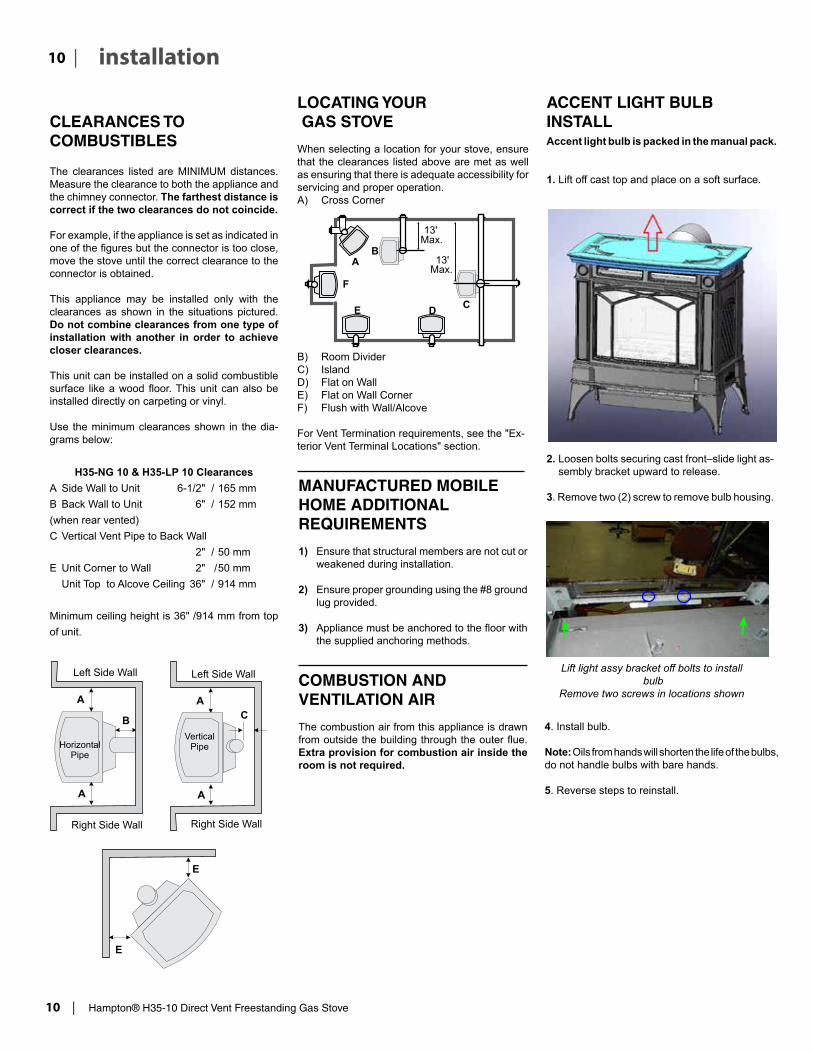
LOCATING YOUR GAS STOVE When selecting a location for your stove, ensure that the clearances listed above are met as well as ensuring that there is adequate accessibility for servicing and proper operation.A) Cross Corner
MANUFACTURED MOBILE HOME ADDITIONAL REQUIREMENTS
1) Ensure that structural members are not cut or weakened during installation.
2) Ensure proper grounding using the #8 ground lug provided.
3) Appliance must be anchored to the floor with the supplied anchoring methods.
COMBUSTION AND VENTILATION AIR
The combustion air from this appliance is drawn from outside the building through the outer flue. Extra provision for combustion air inside the room is not required.
B) Room DividerC) Island D) Flat on WallE) Flat on Wall Corner F) Flush with Wall/Alcove
For Vent Termination requirements, see the "Ex-terior Vent Terminal Locations" section.
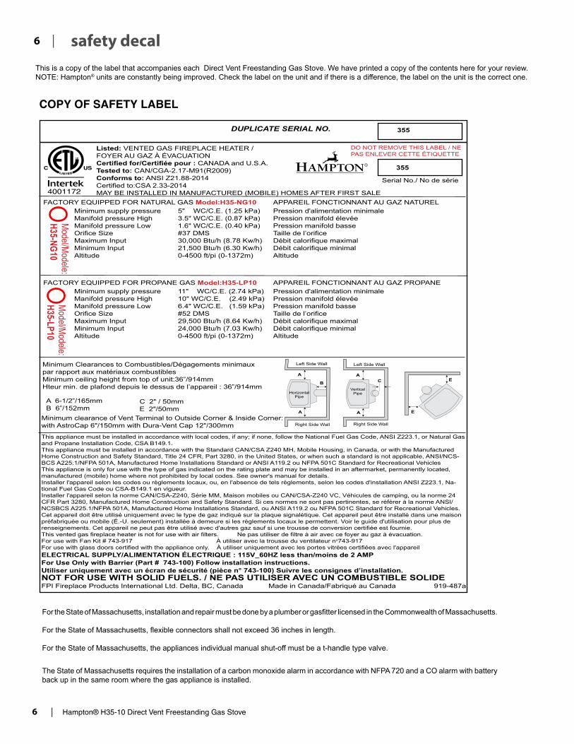
ACCENT LIGHT BULB INSTALLAccent light bulb is packed in the manual pack.
1. Lift off cast top and place on a soft surface.
2. Loosen bolts securing cast front–slide light as-sembly bracket upward to release.
3. Remove two (2) screw to remove bulb housing.
Lift light assy bracket off bolts to install bulb
Remove two screws in locations shown
4. Install bulb.
Note: Oils from hands will shorten the life of the bulbs,do not handle bulbs with bare hands.
5. Reverse steps to reinstall.

Hampton® H35-10 Direct Vent Freestanding Gas Stove | 11
11| installation
OPTIONAL FAN INSTALLATIONH35
919-520a 04.13.15
OPTIONAL FAN INSTALLATION
Remove
Loosen
Fan Installation Kit Includes: 1- Fan Assembly c/w green ground wire attached1- Fan Grey Cable attached to the Fan Assembly1- Small Plastic Grommet1- Big Plastic grommet
2. Remove the rear access panel on the back of the unit by removing 3 top screws and loosening the bottom 3 screws.
NOTE: DO NOT damage, cut or remove the 3” aluminium air intake pipes.
3. Install fan onto the 2 pins on the base panel. Fan Grey cable is already attached to the fan assembly.
4. Connect the green wire to the grounding lug.
6. Run the Fan Grey wire through the large grommet on the base panel to the bottom of the unit.
5. Open the bottom cover of the unit by loosening the 2 screws and removing one from the left side of the unit (when facing back of the unit).
7. Run the fan grey wire through the small grommet power cord from the valve cover plate to the base panel through the large grommet.
8. Attach the connectors (black and red) of Fan Grey wire to the IFC connectors (black and red).
NOTE: Do remember to follow the wire color code, i.e., black to black and red to red). Refer to the picture above.
9. Reinstall the bottom cover of the unit with 1 screw at the left side of the unit (when facing back of the unit) and tightening the 2 screws at the back.
10. Reattach the rear panel cover with 3 screws at the top of the cover and tightening the 3 at the bottom of the panel.
11. Reconnect gas and power supply.
12. To remove fan-reverse steps.
NOTE:• 120 Volt AC power is needed for the fan switch and blower.• Unit must be grounded at all times.• Do not cut the ground terminal off under any circumstances.
Large Grommet
Remove this screw
ConnectorsSmall Grommet
WARNING: Electrical Grounding InstructionsThis appliance is equipped with a three pronged (ground-ing) plug for your protection against shock hazard and should be plugged directly into a properly grounded three-prong receptacle. Do not cut or remove the grounding prong from this plug.
1. Shut off gas and electrical supply.
RESETSWITCH
Thermostat( Optional)(Millivolt)

12 | Hampton® H35-10 Direct Vent Freestanding Gas Stove
| 12 installation
ROTATING 45O ELBOW FOR STRAIGHT HORIZONTAL TERMINATIONS
1) Remove the cast top.
2) Unscrew upper rear panel mounting screws using Phillips head screw driver.
3) Remove upper panel.
4) Remove all the 4 screws that secure elbow to unit using a 1/4" magnetic nut driver.
5) Rotate elbow 180O.
6) Secure the elbow with 4 screws.
7) Reverse steps 6-1 to reinstall the upper rear panel.
SCREEN REMOVAL
1) Remove the cast top.
2) Undo the top cast grill mounting bolts using 7/16" or 11mm socket.
4) Remove top cast grill.
5) Remove the safety screen.
3) Remove light assembly and carefully set aside.

Hampton® H35-10 Direct Vent Freestanding Gas Stove | 13
13| installation
FRONT CAST REMOVAL
1) Remove the cast top from the unit.
2) Remove top cast grill mounting bolts using 7/16" or 11mm socket.
3) Remove top cast grill by pulling it up.
5) Loosen front casting mounting bolts using a 7/16" or 11 mm socket.
6) Open the valve aceess door and loossen the bottom front casting bolts using the same tool.
7) Slide the casting out of the base plate and the side bracket key hole slots and lift the front casting off the unit.
4) Remove light assembly and carefully set aside.

14 | Hampton® H35-10 Direct Vent Freestanding Gas Stove
| 14 installation
INSTALLATION PRECAUTIONS
These venting systems are engineered products that have been designed and tested for use with the H35-NG10, and H35-LP10. The warranty will be voided and serious fire, health or other safety hazards may result from any of the following actions:
1) Installation of any damaged Direct Vent compo-nent
2) Unauthorized modification of the Direct Vent System
3) Installation of any component part not approved by FPI - Fireplace Products International Ltd.
4) Installation other than as instructed by the ap-proved rigid pipe manufacturers and FPI Fireplace Products International Ltd.
Warning: Always maintain required clearances (air spaces) to nearby com-bustibles to prevent a fire hazard. Do not fill air spaces with insulation.
Be sure to check the vent termination clearance requirements from decks, windows, soffits, gas regulators, air supply inlets and public walkways as specified in the "Exterior Vent Terminal Locations" section and in your local building codes.
The gas appliance and vent system must be vented directly to the outside of the building, and never be attached to a chimney serving a separate solid fuel or gas-burning appliance. Each direct vent gas appliance must use it's own separate vent system. Common vent systems are prohibited.
SAFETY PRECAUTIONS FOR THE INSTALLER
1) Wear gloves and safety glasses for protection.
2) Exercise extreme caution when using ladders or on roof tops.
3) Be aware of electrical wiring locations in walls and ceilings.
Note: These flue pipes must not be connected to any other appliance.
The gas appliance and vent system must be vented directly to the outside of the building, and never be attached to a chimney serving a separate solid fuel or gas burning appliance. Each direct vent gas appliance must use it's own separate vent system. Common vent systems are prohibited.
IMPORTANT
Read all instructions carefully before starting the installation. Failure to follow these instructions may create a fire or other safety hazard, and will void the warranty. Be sure to check the venting and clear-ance to combustible requirements. Consult your local building codes before beginning installation.
The location of the termination cap must conform to the requirements in the "Exterior Vent Terminal Locations" section.
VENT RESTRICTOR POSITION
Vent restriction is required for certain venting instal-lations, see the diagrams in "Venting Arrangement" section to determine if they are required for your installation.
To set the Vent restriction as indicated in the dia-grams in the "Venting Arrangement" section, simply loosen the screws and push the vent restrictor plate to the correct position. Tighten the screws.
Horizontal Termination: Position "A"
Vertical Termination: Position "B"
VENTING INTRODUCTIONThe Horizontal Termination Kit and the rigid pipe venting systems, in combination with the Direct Vent Freestanding Gas Stoves, H35-NG10 and H35-LP10, have been tested and listed as direct vent heater systems by Warnock Hersey.
These units use the "balanced flue" technology Co-Axial system. The inner liner vents products of combustion to the outside while the outer pipe draws outside combustion air into the combus-tion chamber thereby eliminating the need to use heated room air for combustion and losing warm room air up the chimney.

Hampton® H35-10 Direct Vent Freestanding Gas Stove | 15
15| installation
EXTERIOR VENT TERMINAL LOCATIONS
Minimum Clearance Requirements Canada1 USA2
A Clearance above grade, veranda, porch, deck, or balcony 12"(30cm) 12"(30cm)
B Clearance to window or door that may be opened 12"(30cm) 9" (23cm)
C Clearance to permanently closed window * *
D Vertical clearance to ventilated soffit located above the terminal within a horizontal distance of 2 feet (61cm) from the center line of the terminal (check with the local code)
22"(56cm) 22"(56cm)
E Clearance to unventilated soffit 12"(30cm) 12"(30cm)
F Clearance to outside corner: with AstroCap and Vent Riser Termination Caps 6"(15cm) 6"(15cm)
Clearance to outside corner: with all other approved Termination Caps 12"(30cm) 12"(30cm)
G Clearance to inside corner: with AstroCap and Vent Riser Termination Caps 6"(15cm) 6"(15cm)
Clearance to inside corner: with all other approved Termination Caps 12"(30cm) 12"(30cm)
H Clearance to each side of center line extended above meter/regulator assembly 36"(90cm)a *
J Clearance to service regulator vent outlet 36"(90cm) *
K Clearance to non-mechanical air supply inlet to building or the combustion air inlet to any other appliance 12"(30cm) 9" (23cm)
L Clearance to a mechanical air supply inlet #3' (91cm) above if within 10' (3m) horizontally.
72"(1.8m) 36"(90cm)b
M Clearance above paved sidewalk or a paved driveway located on public property 84"(2.1m)┼ *
N Clearance under veranda, porch, deck, or balcony 12"(30cm)‡ *
1 In accordance with current CSA B149.1, Natural Gas and Propane Installation Code2 In accordance with the current ANSI Z223.1/NFPA 54, National Fuel Gas Code┼ A vent shall not terminate directly above a sidewalk or paved driveway which is located between two single family dwellings and serves both dwellings.‡ Permitted only if veranda, porch, deck, or balcony is fully open on a minimum of two sides beneath the floor
* Clearance in accordance with local installation codes and the requirements of the gas suppliera 3 feet (91cm) within a height of 15 feet (4.5m) above the meter / regulator assemblyb 3 feet (91cm) above - if within 10 feet (3m) horizontally

16 | Hampton® H35-10 Direct Vent Freestanding Gas Stove
| 16 installation
4” X 6-5/8” RIGID PIPE CROSS REFERENCE CHART ONLYComponents from different Manufacturers may not be mixed. Not All Rigid Pipe components are available directly from FPI.
Description SimpsonDirect Vent Pro®
SelkirkDirect Temp™
American MetalProducts®Amerivent Direct
Metal-Fab™Sure Seal
SecuritySecure- Vent®
ICC Excel Direct
OlympiaVentis DV*
6” Pipe Length-Galvanized 46DVA-06 4DT-6 N/A 4D6 SV4L6 TC-4DL6 VDV-0406
6” Pipe Length-Black 46DVA-06B 4DT-6B N/A 4D6B SV4LB6 TC-4DL6B VDVB-0406
7” Pipe Length-Galvanized N/A N/A 4D7 N/A N/A N/A N/A
7” Pipe Length-Black N/A N/A 4D7B N/A N/A N/A N/A
9” Pipe Length-Galvanized 46DVA-09 4DT-9 N/A N/A N/A TC-4DL9 VDV-0409
9” Pipe Length-Black 46DVA-09B 4DT-9B N/A N/A N/A TC-4DL9B VDVB-0409
12” Pipe Length-Galvanized 46DVA-12 4DT-12 4D12 4D12 SV4L12 TC-4DL1 VDV-0412
12” Pipe Length-Black 46DVA-12B 4DT-12B 4D12B 4D12B SV4LB12 TC-4DL1B VDVB-0412
18” Pipe Length-Galvanized 46DVA-18 4DT-18 4D18 4D18 SV4LA TC-4DL18 VDV-0418
18” Pipe Length-Black 46DVA-18B 4DT-18B 4D18B 4D18B SV4LA TC-4DL18B VDVB-0418
24” Pipe Length-Galvanized 46DVA-24 4DT-24 4D24 4D24 SV4L24 TC-4DL2 VDV-0424
24” Pipe Length-Black 46DVA-24B 4DT-24B 4D24B 4D24B SV4LB24 TC-4DL2B VDVB-0424
36” Pipe Length-Galvanized 46DVA-36 4DT-36 4D36 4D36 SV4L36 TC-4DL3 VDV-0436
36” Pipe Length-Black 46DVA-36B 4DT-36B 4D36B 4D36B SV4LB36 TC-4DL3B VDVCB-0436
48” Pipe Length-Galvanized 46DVA-48 4DT-48 4D48 4D48 SV4L48 TC-4DL4 VDV-0448
48” Pipe Length-Black 46DVA-48B 4DT-48B 4D48B 4D48B SV4LB48 TC-4DL4B VDVB-0448
60” Pipe Length-Galvanized 46DVA-60 4DT-60 N/A N/A N/A N/A N/A
60” Pipe Length-Black 46DVA-60B 4DT-60B N/A N/A N/A N/A N/A
Adjustable Length 3”-10”-Galvanized N/A N/A N/A 4DAL N/A TC-4DLT N/A
Adjustable Length 3”-10”-Black N/A N/A N/A 4DALB N/A TC-4DLTB N/A
Adjustable Length 7”-Galvanized N/A N/A 4D7A N/A N/A N/A N/A
Adjustable Length 7”-Black N/A N/A 4D7AB N/A N/A N/A N/A
Extension Pipe 8-1/2”-Galvanized 46DVA-08A N/A N/A N/A N/A N/A N/A
Extension Pipe 8-1/2”-Black 46DVA-08AB N/A N/A N/A N/A N/A N/A
Adjustable Length 12”-Galvanized N/A N/A 4D12A N/A SV4LA12 TC-4dLSI N/A
Adjustable Length 12”-Black N/A N/A 4D12A N/A SV4LBA12 TC-4dLSIB N/A
Extension Pipe 16”-Galvanized 46DVA-16A N/A N/A N/A N/A N/A N/A
Extension Pipe 16”-Black 46DVA-16AB N/A N/A N/A N/A N/A N/A
45º Elbow-Galvanized 46DVA-E45 4DT-EL45 4D45L N/A N/A TE-4DE45 VDV-EL0445
45º Elbow-Black 46DVA-E45B 4DT-EL45B 4DT-EL45B N/A N/A TE-4DE45B VDVB-EL0445
45º Elbow Swivel-Galvanized See 46DVA-E45 N/A N/A 4D45L SV4E45 N/A N/A
45º Elbow Swivel-Black See 46DVA-E45B N/A N/A 4D45LB SV4EB45 N/A N/A
90º Elbow-Galvanized 46DVA-E90 4DT-EL90S 4DT-EL90S N/A N/A TE-4DE90 VDV-EL0445
90º Elbow-Black 46DVA-E90B 4DT-EL90SB 4DT-EL90SB N/A SV4EBR90-1 TE-4DE90B VDVB-EL0445
90º Elbow, Swivel-Galvanized See 46DVA-E90 N/A N/A 4D90L SV4E90-1 N/A N/A
90º Elbow, Swivel-Black See 46DVA-E90B N/A N/A 4D90LB SV4EB90-1 N/A N/A
90º Starter Elbow, Swivel-Galvanized N/A N/A N/A 4D90A N/A N/A N/A
Adaptor* N/A N/A N/A 4D90L N/A N/A VDV-UAA04
4” X 6-5/8” RIGID PIPE CROSS REFERENCE CHARTComponents from different Manufacturers may not be mixed. Not all rigid pipe components are available directly from Regency.Note: The listed manufacturers may have other lengths not shown on this chart, which would also be approved.
Ceiling Support N/A 4DT-CS 4DSP 4DFSP SV4SD TM4-RDS VDV-SCR04
Cathedral Support Box 46DVA-CS 4DT-CSS 4DRSB 4DRS SV4CSB TM4-SDS VDV-CSS04
Wall Support/Band 46DVA-WS 4DT-WS/B 4DWS 4DWS SV4BM TM-SWS VDV-WS04
Offset Support 46DVA-ES - N/A from FPI
4DT-OS N/A N/A SV4SU TM-SOS N/A
Wall Thimble-Black 46DVA-WT 4DT-WT 4DWT 4DWT SV4RSM N/A VDV-WPT04
Wall Thimble Support/Ceiling Support 46DVA-DC N/A N/A N/A SV4PF N/A N/A
Firestop Spacer 46DVA-FS 4DT-FS 4DFSP 4DFS SV4BF TM-4CS VDV-FS04
Trim Plate-Black N/A 4DT-TP 4DFPB 4DcP SV4LA TM-4TP VDV-WTC04

Hampton® H35-10 Direct Vent Freestanding Gas Stove | 17
17| installation
Description SimpsonDirect Vent Pro®
SelkirkDirect Temp™
American MetalProducts®Amerivent Direct
Metal-Fab™Sure Seal
SecuritySecure- Vent®
ICC Excel Direct
OlympiaVentis DV*
Attic Insulation Shield 12” 46DVA-IS N/A@ FPI N/A 4DAIS12 N/A SV4RSA N/A VDV-AIS04
Attic Insulation Shield - Cold Climates 36” N/A N/A 4DAIS12 N/A N/A TM-4AS N/A
High Wind Vertical Cap 46DVA-VCH N/A N/A N/A N/A TM-4VT VDV-VCHW04
High Wind Horizontal Cap N/A N/A N/A N/A N/A TM-4DHT N/A
Horizontal Square Termination Cap 46DVA-HC 4DT-HHC 4DHC 4DHT SV4CHC-1 TM-4HT VDV-HC04
Vertical Termination Cap 46DVA-VC 4DT-HVC 4DVC 4DVT SV4CGV-1 N/A N/A
Storm Collar 46DVA-08A 4DT-SC 4DSC 4DSC SV4FC TM-SC VDV-SC04
Restrictor Disk N/A N/A N/A N/A N/A TM-4DS N/A
Extended Vertical Termination Cap N/A N/A N/A N/A N/A N/A N/A
Chimney Conversion Kit A (USA only) 46DVA-KCA N/A N/A N/A N/A TM-4CA6 N/A
Chimney Conversion Kit B (USA only) 46DVA-KCB N/A N/A N/A N/A TM-4CA7 N/A
Chimney Conversion Kit C (USA only)
46DVA-KCC N/A N/A N/A N/A TM-4CA8 N/A
Wall Firestop 46DVA-WFS N/A N/A N/A N/A TM-4TR VDV-FS04
Colinear Flex Connectors 46DVA-ADF N/A N/A N/A N/A N/A N/A
Adjustable Flashing 0/12-6/12 46DVA-F6 4DT-ST14 4D12S 4DST14 SV4STC14 TF-4FA VDV-F0406
Adjustable Flashing 6/12-12/12 46DVA-F12 4DT-ST36 4D36S 4DST36 SV4STC36 TF-4FB VDV-SSO
Vinyl Siding Standoff 46DVA-VSS 4DT-VS N/A 4DVS SV4VS TM-VSS N/A
Vinyl Siding Shield Plate N/A 4DT-VSP N/A N/A SV4VS N/A N/A
Snorkel Termination 14” 46DVA-SNK14 N/A N/A N/A N/A TM-4ST14 N/A
Snorkel Termination 36” N/A N/A N/A N/A N/A TM-4ST36 N/A
Basic Horizontal Termination Kit (A) Disc. 4DT-HKA 4DHTK2 4DHTKA SV-SHK TM4-HTK VDV-KW04
Horizontal Termination Kit (B) 46DVA-KHA(Changed Components)
4DT-HKB 4DHTK1 4DHTKB SV-HK TM4-HTK VDV-K04
Vertical Termination Kit Disc. 4DT-VKC 4DHTK 4DHTK SV-FK N/A N/A
FPI
946-506/P Vent Guard (Optional) for AstroCap 946-205 Vinyl Siding Shield for Riser Vent Terminal
**510-994 Rigid Pipe Adaptor (Must use with all rigid piping) 946-208/P Vent Guard (Optional) for Riser Vent Terminal
640-530/P Riser Vent Terminal 946-523/P AstroCap Horizontal Cap
946-206 Vinyl Siding Standoff for AstroCap
** The rigid pipe adaptor is not required on the C34, U39, H15, H27, H35 & RC500E.Note: When using Metal-Fab Sure Seal Rigid Piping - please note that the Adaptor (4DDA) must be used in conjunction with FPI Rigid Pipe Adaptor (510-994).
Note: Horizontal runs of vent must be level, or have a 1/4” rise for every 1 foot of run towards the termination. Never allow the vent to run downward - this could cause high temperatures and may present a possible fi re hazard.
Offset Pipe Selection: Use this table to determine offset pipe lengths.
Pipe Length(L)
4” x 6-5/8” Venting For specifi c instructions on venting components - visit the manufacturers website listed below.
Run (X) Rise (Y)
0” (0mm) 4-7/8” (124mm) 13-7/8” (340mm) Simpson Direct Vent Pro: www.duravent.com
6” (152mm) 8” (203mm) 16-1/2” (419mm) Selkirk Direct-Temp: www.selkirkcorp.com
9” (229mm) 10-1/8” (257mm) 18-5/8” (473mm) American Metal Products: www.americanmetalproducts.com
12” (305mm) 12-1/4” (311mm) 20-3/4” (527mm) Metal-Fab Sure Seal: www.mtlfab.com
24” (610mm) 20-5/8” (524mm) 29-1/8” (740mm) Security Secure Vent: www.securitychimneys.com
36” (914mm) 29” (737mm) 37-1/2” (953mm) Industrial Chimney Company: www.icc-rsf.com
48” (1219mm) 37-7/16” (951mm) 45-15/16” (1167mm) Olympia Ventis DV: www.olympiachimney.com
* Olympia Ventis DV applicable for the following units only: B36XTE, B36XTCE, B41XTE, B41XTCE, CV40E, CB40E, CC40E, CV72E, P36, P36E, RC500E

18 | Hampton® H35-10 Direct Vent Freestanding Gas Stove
| 18 installation
RIGID PIPE VENTING SYSTEMSHorizontal or Vertical Terminations
Alternate Horizontal Termination Caps
The FPI AstroCapTM and FPI Riser Vent terminal are certified for installations using FPI venting systems as well as Simpson Dura-Vent® Direct Vent Pro, American Metal Products Ameri Vent Direct Vent, Security Secure Vent®, Selkirk Direct-Temp. AstroCapTM is a proprietary trademark of FPI Fireplace Products International Ltd. Dura-Vent® and Direct Vent Pro are registered and/or proprietary trademarks of Simpson Dura-Vent Co. Inc.
This product has been evaluated by Intertek for use with Duravent Direct-Vent Pro, Selkirk Direct-Temp, Ameri Vent Direct venting and Security Secure Vent systems.
WARNING:
Do not combine venting components from different venting systems.
However use of the the AstroCapTM and FPI Riser is acceptable with all systems.
When using Rigid Vent other thanSimpson Dura-Vent, 3 screws must be used to secure rigid pipe to adaptor.

Hampton® H35-10 Direct Vent Freestanding Gas Stove | 19
19| installation
Offset to Vertical Terminations
VENTING ARRANGEMENTS
Vertical Terminations Systems for Residential Manufactured and Mobile Homes
The shaded area in the diagram below shows all allowable combinations of straight vertical and offset to vertical runs with vertical terminations. Maximum two 45o elbows.
If the vent is ENCLOSED in a chase (min. size 9" x 9") maintain a 1-1/4" clearance to combustibles.May be installed in Manufactured (Mobile) Homes after first sale.
Horizontal Terminations for All Venting Systems
The shaded areas in the diagram below show all allowable combinations of vertical runs with horizontal terminations. Maximum one 90O elbow (two 45o elbows equal one 90o elbow). All approved caps listed on page 12 - may be used.
Propane and Natural Gas: Residential, Manufactured and Mobile Homes Installations
The venting arrangements diagrammed below, have a min. of 75% (flue loss) efficiency with Fan Off, as required for manufactured homes. (Actual efficiency may be as high as 85%)
May be installed in Manufactured (Mobile) Homes after first sale.
NOTE: See "Vent Restrictor Position" section for installation instructions for the Vent Restrictor Position.

20 | Hampton® H35-10 Direct Vent Freestanding Gas Stove
| 20 installation
VENTING ARRANGEMENTS HORIZONTAL TERMINATIONS USING RIGID PIPE
Snorkel Termination Riser Vent Termination
The two diagrams show all allowable com-binations of straight horizontal termination using Rigid Pipe. Restrictor position "A".Only a snorkel or FPI Riser vent may be used as shown. No other termination cap is permitted.
Venting Arrangements -Straight Horizontal Termination
The diagrams show all allowable combina-tions of straight horizontal termination using Rigid Pipe. Restrictor position "A".
Only a snorkel or FPI Riser vent may be used as shown in the noted diagrams. No other termination cap is permitted.
Dangerous operating conditions will occur if these instructions are not adhered to.
*If this is an outside corner, the minimum dis-tance between the vent and the outside corner is 6” (15cm). See “F” on the diagram in the "Exterior Vent Terminal Locations" section.
Snorkel Termination Riser Vent Termination

Hampton® H35-10 Direct Vent Freestanding Gas Stove | 21
21| installation
Horizontal Venting with Two (2) 90o Elbows
Option V H + H1 A) 3' Min. 2' Max. B) 4' Min. 3' Max. C) 5' Min. 4' Max. D) 6' Min. 5' Max. E) 7' Min. 6' Max. F) 8' Min. 8' Max
Horizontal Venting with Two (2) 90o Elbows
Option H V H + H1 A) 1' Max. 2' Min. 3' Max. B) 2' Max. 3' Min. 5' Max. C) 3' Max. 5' Min. 6' Max. D) 4' Max. 7' Min. 7' Max. E) 5' Max. 9' Min. 8' Max.
With these options, max. total pipe length is 30 feet with min. of 9 feet total vertical and max. 8 feet total horizontal.Please note min. 1 footbetween 90o elbows isrequired.
With these options, maxi-mum total pipe length is 30 feet with minimum of 8 feet total vertical and maximum 8 feet total horizontal.Please note minimum 1 foot between 90o elbows is required.
One 90o elbow = Two 45o elbows.
One 90o elbow = Two 45o elbows.
Vent restrictor position A (fully open), refer to the "Vent Restrictor Position" section.
Vent restrictor position A (fully open), refer to the "Vent Restrictor Position" section.
H1
H
V
Lengths do not include elbow indicated
Lengths do not include elbow indicated

22 | Hampton® H35-10 Direct Vent Freestanding Gas Stove
| 22 installation
H1
H
V
Vertical Venting with Two (2) 90o Elbows
Option V H V + V1 A) 1' Min. 3' Max. 2' Min. B) 2' Min. 4' Max. 3' Min. C) 3' Min. 5' Max. 4' Min. D) 4' Min. 6' Max. 5' Min. E) 5' Min. 7' Max. 6' Min.
Vertical Venting with Two (2) 90o Elbows
With these options, max. total pipe length is 30 feet with min. of 6 feet total vertical and max. 7 feet total horizontal.Please note min. 1 foot between 90o elbows is required.
Option H + H1 V A) 2' Max. 2' Min. B) 3' Max. 3' Min. C) 4' Max. 4' Min. D) 5' Max. 5' Min. E) 6' Max. 6' Min.
With these options, max. total pipe length is 30 feet with min. of 6 feet total vertical and max. 6 feet total horizontal.Please note min. 1 foot between 90o elbows is required.
One 90o elbow = Two 45o elbows.
One 90o elbow = Two 45o elbows.
Vent restrictor position A (fully open), refer to the "Vent Re-strictor Position" section.
Vent restrictor position A (fully open), refer to the "Vent Restrictor Position" section.
Lengths do not include elbow indicated
Lengths do not include elbow indicated

Hampton® H35-10 Direct Vent Freestanding Gas Stove | 23
23| installation
Venting Arrangements - Vertical Terminations with Co-linear Flex System for bothResidential & Manufactured Homes into Masonry Fireplaces
The shaded area in the diagram shows the allowable vertical terminations. Note: Must remove 4 screws from stove collar and rotate 180o to have collar facing straight back. Secure into place with 4 screws.
VERTICAL TERMINATION WITH CO-LINEAR FLEX SYSTEM
THE APPLIANCE MUST NOT BE CONNECTED TO A CHIMNEY FLUE SERVING A SEPARATE SOLID FUEL
BURNING APPLIANCE.
This appliance is designed to be attached to two 3" (76mm) co-linear aluminium flex running the full length of the chimney. See the Venting Arrangements chart below for minimum and maximum flue lengths. See chart below for minimum distances from roof. Periodically check that the vent is unrestricted.
Masonry chimneys may take various contours which the flexible liner will accommodate. However, keep the flexible liner as straight as possible, avoid unnecessary bending.
The Air Intake pipe must be attached to the inlet air collar of the termination cap.
Straight Vertical Terminations
Required Parts:Part # Description946-529 Co-linear DV Vertical Termination Cap948-305 3" Flex - 35 ft.946-563 Co-Axial to Co-Linear Adaptor Kit which contains the following: Co-linear Flex Adaptor Outer Pipe Inner Pipe Adaptor
Vent Restrictor set at 1-3/4" open (fully open), Position "A"

24 | Hampton® H35-10 Direct Vent Freestanding Gas Stove
| 24 installation
Note: a) Liner sections should be
continous without any joints or seams.
b) This is an approved system, therefore components in this system must not be substituted for any other manufacturer's products.
Review the following sequence of instructions which are typical of most installations. The sequence may vary depending on wall thickness. See "Exterior Vent Terminal Locations" to "Venting Arrange-ments" section for vent location and clearance dimensions, and the "Vent Restrictor Position" section to set the Vent Restrictor to the cor-rect position.
1) Set the unit in its desired location. Check to determine if wall studs will be in the way of the venting system, adjust location until all clear-ances are met and there are no obstructions.
Note: A 1-1/2"(38mm) clearance around the outer pipe must be maintained except that only a 1" (25mm) clearance is needed at the termination end.
IMPORTANT:Do not locate termination hood where excessive snow or ice buildup may occur. Be sure to check vent termina-tion area after snow falls, and clear to prevent accidental blockage of vent-ing system. When using snow blow-ers, make sure snow is not directed towards vent termination area.
b) Install wall thimbles on both interior and exterior wall with 4 wood screws (#8 x 1") per thimble.
c) Attach the 2 piece adjustable pipe section to the vent terminal and slide into position from the exterior. The larger diameter end of the adjustable pipe goes to the vent terminal.
d) Install the 90o elbow onto the adjustable pipe to determine the vertical centerline.
Note: if the centerline cannot be met, the adjustable sections will have to be cut.
e) Cut the 4 ft. section of rigid pipe to length. Attach the 45o elbow to the rigid pipe, and ensure that the pipe length when cut (with the 45o elbow) will seat onto both the starter collar and the 90o elbow. Crimped section of rigid pipe seats into the 90o elbow. Only cut the uncrimped side of pipe.
Dismantle all pipe sections including vent terminal.
2) Assemble a trial fit to determine the vertical center-line for the vent termination.
a) Cut a 9-1/2" x 9-1/2" (241mm x 241 mm) square hole on both the interior and exterior wall.
DV STOVE HORIZONTAL TERMINATION VENT KIT
DV 2 ft. Stove Vent Kit (Part # 946-116) and DV 4 ft. Stove Vent Kit (Part #946-216) includes all the parts needed to install the H35 Direct Vent unit with minimum horizontal and vertical vent dimensions. For in-stallations that require longer vertical and/or horizontal vents use the Dura-Vent system as shown in the "Dura-Vent Termination Kit" and "Dura-Vent Venting Components" sections.
Qty. Description1) 1 Rigid Pipe Section (Kit # 946-116: 2 ft. (1.2m) length, Kit # 946-216: 4 ft. (1.2m) length), 6-1/2" (165mm) inside diameter 2) 1 Flex Liner, compressed aluminium 2 ply liner, 4" (102mm) inside diameter3) 4 Spring Spacers4) 1 90 deg. Elbow5) 1 Adjustable pipe section 13-1/2" to 24" (343mm x 610mm), 2 pcs.6) 1 Thimble Cover7) 1 Wall Thimble (2 pcs.)8) 1 Adaptor 9) 1 AstroCap Termination Cap10) 2 Trim Collars11) 1 Tube of Mill-Pac, high temperature sealant12) 12 Screws, #8 x 1/2" Self tapping, Stainless Steel13) 14 Screws, #8 x 1/2" Self tapping, Black14) 4 Screws #8 x 1-1/2" Drill Point, Black15) 4 Screws #8 x 1-1/2" Drill Point, Stainless Steel16) 8 Wood screws #8 x 1"
Required but not included in above Kit: 45o Elbow (Part #: 946-1014)
DV STOVE HORIZONTAL VENT KIT (#946-116 & #946-216) INSTALLATION

Hampton® H35-10 Direct Vent Freestanding Gas Stove | 25
25| installation
Outside Wall
Mur extérieur
FurringStrips
Fourrures en bois
Furstrp.eps
see also c34020a.eps
furstrpf.epsfrench
Note: The pipe seam should be facing down.
Note: To make the installation more aestheti-cally pleasing, we recommend framing out a square that the cap can be mounted on.
3) Attach the 4" dia. flex liner to the vent terminal ensuring that the flex overlaps the collar of the vent terminal by a minimum of 1-3/8"(35mm). Use Mill-Pac to seal and secure with 3 of the #8 x 1/2" screws (stainless steel).
4) Attach the adjustable pipe section to the vent
terminal using Mill-Pac wand attach with 3 of the #8 x 1/2" screws (stainless steel).
NOTE: For best results and optimum perfor-mance with each approved venting sys-tem, it is highly recommended to apply “Mill-Pac” sealant (supplied) to every inner pipe connection. Failure to do so may result in drafting or performance issues not covered under warranty.
5) Slide the partially connected pipe and vent terminal assembly through the wall thimbles (from the exterior into the interior) and secure the cap to the exterior wall with 4 of the supplied screws (#8 x 1-1/2" drill point, stainless steel). Note: pilot holes will need to be drilled through the wall thimble on all 4 corners.
Note: The four screws provided for the vent cap should be replaced with appropriate fasteners for stucco, brick, concrete, or other types of sidings.
6) A bead of non-hardening mastic should be run around both the termination and vinyl siding standoff to prevent water from entering and to make a tight seal between the cap and the standoff.
7) Stretch the 4" dia. flex liner out fully and get a trial fit of the liner onto the 4" dia. starter collar.
8) Cut the 4" dia. flex liner to the desired size.
Hint: leave an extra 12" to 16" of length, this will make the final assembly easier to work with.
9) Secure the 4" dia. flex liner to the 4" adaptor with Mill-Pac and 3 of the #8 x 1/2" screws (stainless steel).
10) Slide the decorative Thimble Cover over the pipe sections and secure with 4 screws (#8 x 1-1/2" drill point, black) to the wall.
11) Slide the 90o elbow (crimp end up), the 45o elbow and the 4 ft. pipe section (crimp end up) over the 4" dia. flex liner.
12) Install the spring spacers onto the pipe sections.
13) Secure the 4" dia. flex liner with adaptor onto the stove collar. Put a bead of Mill-Pac around the appliance adaptor and secure with 3 screws (#8 x 1/2, stainless steel).
14) Attach the 45o elbow onto the starter collar by sealing with Mill-Pac securing with 3 of the #8 x 1/2" (black) screws.
15) Attach the pipe section to the 45o elbow by sealing with Mill-Pac securing with 3 of the #8 x 1/2" screws (black). Pipe seams should be facing the wall.
16) Attach the 90o elbow onto the pipe section by sealing with Mill-Pac securing with 3 of the #8 x 1/2" screws (black).
17) Slide the adjustable pipe section onto the 90o elbow. Slide the trim collar over the adjustable pipe sections to cover the joint of the telescopic section.) The flex may have to be compressed back in order for the adjustable pipe to properly mate to the elbow. Seal with Mill-Pac secure with 3 of the #8 x 1/2" screws (black). Pipe seams facing down.
18) Install the trim collar over the starter collar and secure with a #8 x 1/2" screw (black).
If the pipe needs to be touched up, use only Stove Brite High Temperature Metallic Black Stove Paint.
Note: If installing termination on a siding covered wall, a vinyl siding standoff or furring strips must be used to ensure that the termination is not recessed into the siding. For vinyl siding standoff installa-tion refer to the Dura-Vent Termination instructions.

26 | Hampton® H35-10 Direct Vent Freestanding Gas Stove
| 26 installation
Pipe Length
Round SupportBox/Wall Thimble
VerticalTerminal
Storm Collar
Flashing
CeilingFirestop
*24" Pipe Length
Dura-Vent Horizontal
Termination Installation
Dura-Vent Vertical
Termination Installation
*Adj.Pipe Length
*90 Elbowo
*Round SupportBox/Wall Thimble
*HorizontalTermination Cap
Wall Thimble(B)
Vinyl SidingStandoff (Optional)
CathedralCeiling
Support Box
(D)
Vertical Termination Kit
(A)
*Horizontal Termination Kit
Dura-Vent Basic Horizontal Kit # 46DVA-KHA
1 90o Elbow1 Wall Thimble Cover1 Horiz. Sq. Term. Cap
DURA-VENT TERMINATION KIT
Planning Your Dura-Vent Installation
There are two basic types of Dura-Vent Direct Vent System installations: horizontal termination and ver-tical termination. Confirm the maximum horizontal run and maximum vertical rise from the diagrams in the "Venting Arrangement" section.
When planning your installation, it will be necessary to select the proper length of vent pipe for your particular requirements. For horizontal installations, determine the minimum clearance from the rear of the unit to the wall. It is also
important to note the wall thickness. (The wall thimble is suitable for 2 x 4 or 2 x 6 wall construc-tion.) Select the amount of vertical rise desired for "vertical-to-horizontal" type installations.
Warning: Always maintain required clearances (air spaces) to nearby combustibles to prevent a fire hazard. Do not fill air spaces with insulation.
The minimum clearance requirements between the outer wall of the vent pipe and nearby combustible surfaces is 1-1/4 inch. Be sure to check
the vent termination clearance requirements from decks, windows, soffits, gas regulators, air sup-ply inlets and public walkways as specified in the "Exterior Vent Terminal Locations" section and in your local building codes.
To determine the length of vent pipe required for vertical installations, measure the distance from the unit flue outlet to the ceiling, the ceiling thickness, the vertical rise in an attic or second storey, and allow for sufficient vertical height above the roof line.
For multi-storey applications, fire stops are required at each floor level. If an offset is needed, additional pipe, elbows and supports will be required.
Do not exceed the maximum number of elbows. One 90o for horizontal terminations and two 45o for vertical termination.
Alternate Horizontal Termination Caps

Hampton® H35-10 Direct Vent Freestanding Gas Stove | 27
27| installation
Diagram 2a
Diagram 3
Below Grade Snorkel Installation If the Snorkel Termination must be installed
below grade, i.e. basement application, proper drainage must be provided to prevent water from entering the Snorkel Termination. Refer to Vent Manufacturer Installation instructions for details. Do not attempt to enclose the Snorkel within the wall, or any other type of enclosure.
3) With the pipe attached to the stove, slide the stove into its correct location, and mark the wall for a 10" x 10" (inside dimensions) square hole. The center of the square hole should line up with the center line of the horizontal pipe, as shown in diagram 3. Cut and frame the 10 inch square hole in the exterior wall where the vent will be terminated. If the wall being penetrated is constructed of non-combustible material, i.e. masonry block or concrete, a 7" diameter hole is acceptable.
*As specified in CAN/CSA B149.1 Installation Code. Local codes or regulations may require different clearances.
Diagram 2
HORIZONTAL INSTALLATIONSRIGID VENT SYSTEM
1) Set the unit in its desired location. Check to determine if wall studs or roof rafters are in the way when the venting system is attached. If this is the case, you may want to adjust the location of the unit.
2) Direct Vent pipe and fittings are designed with special twist-lock connections to connect the venting system to the appliance flue outlet. A twist-lock appliance adaptor is installed on the unit at the factory. Assemble the desired com-bination of pipe and elbows to the appliance adaptor with pipe seams oriented towards the wall or ceiling, as much out of view as possible. The final positioning of the pipe and 90o elbow assembly is determined by the mounting orienta-tion of the adaptor on the stove and twist-locked for a solid connection.
b) Horizontal runs of vent must be supported every three feet. Wall straps are available for this purpose.
c) Snorkel Terminations: For installations requiring a vertical rise on the\
exterior of the building, 14-inch and 36-inch tall Snorkel Terminations and the Riser Vent as shown in Diagrams 2 & 2a are available. Fol-low the same installation procedures as used for standard Horizontal Termination. NEVER install the snorkel upside down.
Note: a) Twist-lock procedure: Four indentations,
located on the female ends of pipes and fittings, are designed to slide straight onto the male ends of adjacent pipes and fittings, by orienting the four pipe indentations so they match and slide in to the four entry slots on the male ends (Diagram 1). Push the pipe sections completely together, then twist-lock one section clockwise approximately one-quarter turn, until the two sections are fully locked. The female locking lugs will not be visible from the outside on the Black Pipe or fittings. They may be located by examining the inside of the female ends.
NOTE: For best results and optimum perfor-mance with each approved venting sys-tem, it is highly recommended to apply “Mill-Pac” sealant (supplied) to every inner pipe connection. Failure to do so may result in drafting or performance issues not covered under warranty.

28 | Hampton® H35-10 Direct Vent Freestanding Gas Stove
| 28 installation
Diagram 7
Diagram 6
Diagram 5
Diagram 4
b) The location of the horizontal vent termina-tion on an exterior wall must meet all local and national building codes, and must not be blocked or obstructed. See diagram in the "External Vent Terminal Locations" section.
4) If installing the vent termination to a wall with vinyl siding, the Vinyl Siding Standoff must be used. Attach the Vinyl Siding Standoff to the Horizontal Vent Termination, but first run a bead of non-hardening mastic around its outside edges, so as to make a seal between vent cap and the standoff. Install the Vinyl Siding Standoff) between the vent cap and the exte-rior wall and attach with the four wood screws provided. Seal around the Vinyl Siding Standoff on all four sides. Diagram 6. The arrow on the vent cap should be pointing up. Insure that the 1-1/4" clearances to combustible materials are maintained. See diagram 4.
Note: If installing termination on a siding covered wall, a vinyl siding standoff or furring strips must be used to ensure that the termination is not recessed into the siding. The four wood screws provided should be replaced with appropriate fasteners for stucco, brick, concrete, or other types of sidings.
5) Before connecting the horizontal run of vent pipe to the vent termination, slide the black decora-
tive wall thimble cover over the vent pipe, then slide the Wall Thimble over the vent pipe.
6) Slide the appliance and vent assembly towards the wall carefully inserting the vent pipe into the vent cap assembly. It is important that the vent pipe extends into the vent cap a sufficient distance so as to result in a minimum pipe overlap of 1-1/4 inches. Secure the connection between the vent pipe and the vent cap by attaching the two sheet metal strips extend-ing from the vent cap assembly into the outer wall of the vent pipe. Use the two sheet metal screws provided to connect the strips to the pipe. Bend any remaining portion of the sheet metal strip back towards the vent cap, so it will be concealed by the decorative wall thimble cover. See Diagram 5.
7) Install wall thimble in the center of the 10" square and attach with wood screws.
8) Slide the decorative wall thimble up to the wall
VERTICAL TERMINATIONRIGID VENT SYSTEM
1) Maintain the 1-1/4" clearances (air spaces) to combustibles when passing through ceil-ings, walls, roofs, enclosures, attic rafter, or other nearby combustible surfaces. Do not pack air spaces with insulation. Check the "Exterior Vent Terminal Locations" section for the maximum vertical rise of the venting system and the maximum horizontal offset limitations.
2) Set the gas appliance in its desired location. Drop a plumb bob down from the ceiling to the position of the appliance flue exit, and mark the location where the vent will penetrate the ceil-ing. Drill a small hole at his point. Next, drop a plumb bob from the roof to the hole previously drilled in the ceiling, and mark the spot where the vent will penetrate the roof. Determine if ceiling joists, roof rafters or other framing will obstruct the venting system. You may wish to relocate the appliance or to offset, as shown in Diagram 8 to avoid cutting load bearing members.
Note: a) The horizontal run of vent should have a
1/4 inch rise for every 1 foot of run towards the termination. Never allow the vent to run downward. This could cause high tempera-tures and may present the possibility of a fire.
surface being careful not to scratch the paint and attach with screws provided. Apply decorative brass or chrome trim if desired. See Diagram 6.

Hampton® H35-10 Direct Vent Freestanding Gas Stove | 29
29| installation
Roof Pitch Minimum Vent Height Feet Metersflat to 7/12 2 0.61over 7/12 to 8/12 2 0.61over 8/12 to 9/12 2 0.61over 9/12 to 10/12 2.5 0.76over 10/12 to 11/12 3.25 0.99over 11/12 to 12/12 4 1.22over 12/12 to 14/12 5 1.52over 14/12 to 16/12 6 1.83over 16/12 to 18/12 7 2.13over 18/12 to 20/12 7.5 2.29over 20/12 to 21/12 8 2.44
Offset Chart
Diagram 12
7) Ensure vent is vertical and secure the base of the flashing to the roof with roofing rails, slide storm collar over the pipe section and seal with a mastic.
8) Install the vertical termination cap by twist lock-ing it.
Notes: a) For multistorey vertical installations, a Ceil-
ing Fire stop (Part # 46DVA-FS) is required at the second floor, and any subsequent floor. Diagram 12. The opening should be framed to 10 " x 10" inside dimensions, in the same manner as shown in Diagram 9.
b) Any occupied areas above the first floor, including closets and storage spaces, through which the vertical vent passes, must be enclosed.
Diagram 11
Diagram 9
Diagram 8
3) To install the Round Support Box/Wall Thimble in a flat ceiling, cut a 10 inch square hole in the ceiling centred on the hole drilled in Step 2. Frame the hole as shown in Diagram 9.
NOTE: For best results and optimum perfor-mance with each approved venting sys-tem, it is highly recommended to apply “Mill-Pac” sealant (supplied) to every inner pipe connection. Failure to do so may result in drafting or performance issues not covered under warranty.
4) Assemble the desired lengths of black pipe and elbows necessary to reach from the appliance adaptor up though the Round Support Box. Insure that all pipes and elbow connections are in the fully twist-locked position and sealed.
Diagram 10: The upper half of the flashing is installed under the roofing material and not nailed down until the chimney is installed. This allows for
small adjustments.
6) Continue to assemble pipe lengths.
Note: If an offset is necessary in the attic to avoid obstructions, it is important to support the vent pipe every 3 feet, to avoid excessive stress on the elbows, and possible separation. Wall straps are available for this purpose. See Diagram 5.
Galvanized pipe and elbows may be utilized
in the attic as well as above the roof line. The galvanized finish is desirable above the roof line due to its higher corrosion resistance.
Continue to add pipe sections through the flashing until the height of the vent cap meets the minimum height requirements specified in Diagram 11 or local codes. Note that for steep roof pitches, the vertical height must be increased. A poor draft, or down drafting can result from high wind conditions near big trees or adjoining roof lines, in these cases, increasing the vent height may solve the problem.
5) Cut a hole in the roof centred on the small drilled hole placed in the roof in Step 2. The hole should be of sufficient size to meet the minimum requirements for clearance to combustibles of 1-1/4". Slip the flashing under the shingles (shingles should overlap half the flashing) as per Diagram 10.

30 | Hampton® H35-10 Direct Vent Freestanding Gas Stove
| 30 installation
TerminationCap
Top Adaptor
ExistingMetal
ChimneySystem
4" AluminumFlex Pipe
RetroConnector
Any SimpsonDura-Vent
black direct ventpipe plus an
adjustable lengthto make a
proper connection.
CONVERTING CLASS-A METAL CHIMNEY TO DIRECT VENT SYSTEM
Prior to installation and connection of the vent system to a factory-built or masonry chimney, the chimney must be inspected and thoroughly cleaned by a qualified service person, such as a certified chimney sweep or home inspection service. The direct vent system must not be connected to a damaged factory-built or masonry chimney.
For factory built, zero clearance, and masonry chimneys cleanout doors and caps or plugs for cleanout tee fittings and ash dumps shall be secured in place and sealed before installing a Direct Vent system within the chimney.
If the appliance shuts off during operation, contact a qualified service person to determine if a negative pressure and/or leaky chimney condition exists. Do not operate the appliance until the problem is corrected.
Converting a Factory Built Metal Chimney
Important : If converting this appliance to a Factory Built Metal Chimney, the IPI/CPI switch on the hand held remote control/transmitter must be turned to CPI (Continu-ous Pilot Ignition) at all times. This will avoid nuisance pilot outages during operation of this appliance. See Remote manual for setup of this IPI/CPI switch.
1) Remove the existing chimney cap.
2) Measure the distance from the top end of the chimney to the bottom of the ceiling support box, add 3" (76mm) to this measurement, and cut a section of the 4" (102mm) flex pipe to that length (the flex should already be extended to its nominal length).
3) Connect the end of the flex pipe section to the underside of the Top Adaptor using 3 sheet metal screws (refer to Diagram 2).
4) Pass the flex pipe down through the center of the chimney system, and center the adaptor on the top of the chimney pipe. Drill four 1/8" diameter holes through the adaptor and into the chimney top. Insure that you are in fact, drilling into the metal on the chimney. Twist-lock the Termination Cap onto the Adaptor (refer to Diagrams 3 and 4).
Diagram 1
Diagram 2
5) Pull the flex pipe down through the ceiling support box, until it protrudes approximately 3" (76mm). Connect the flex pipe to the Retro Connector by slipping it into the 4-3/4" (121mm) diameter sleeve on the top side of the Con-nector. Use 3 sheet metal screws to assemble these two parts.
6) Push the flex pipe back up into the ceiling support box, center the Retro Connector, and attach it to the support box, or decorative sleeve for double wall solid packed pipe, with the sheet metal screws (supplied). The holes in the Retro Connector are pre-punched (refer to Diagram 5).
Diagram 4
Diagram 5
7) The connection between the appliance and the Retro Connector may be completed with sections of black direct vent pipe, together with an adjustable length.
Diagram 3
Approved for US Installations OnlyThe use of an existing chimney as an air intake is not covered under the ANSI Z21.88a-10007, CSA 2.33a-10007 test methods and the resulting ITS/WHI product certification. The code Author-ity Having Jurisdiction must be consulted prior to proceeding with this installation method.

Hampton® H35-10 Direct Vent Freestanding Gas Stove | 31
31| installation
4) Assemble the desired lengths of Black Pipe and Elbows necessary to reach from the ap-pliance adaptor up through the support box and flashing to proper height as per Diagram 12, local codes or the "Exterior Vent Terminal Locations" section. Ensure that all pipe and elbow connections are in their fully twist lock position.
5) Ensure vent is vertical and secure flashing to the roof with roofing nails. Slide the storm collar over the pipe section and seal with a mastic.
6) Twist lock the vent cap on to the last section.
Support Extensions - Round (RDSE) or Square (SQSE)
Steep pitched cathedral ceilings may require the use of a support extension. This piece fits down inside the support and can be adjusted to increase the support's length by up to 22" (559mm). The extension is attached to the support using the eight metal screws provided. Be sure there is at least a 2" (51mm) overlap where the extension joins the support.
HIGH ELEVATION
This unit is approved in Canada for altitude to 4500 ft. (CAN/CGA-10.17-M91). For Natural Gas installations above 4500 feet, follow current CAN/CSA-B149.1.
GAS CONNECTION
The gas connection is a 3/8" NPT 90o elbow. The gas line can be rigid pipe or to make installation easier, use a listed flexible connector and/or copper tubing if allowed by local codes. Since some mu-nicipalities have additional local codes it is always best to consult with your local authorities and the CAN/CSA B149.1 installation codes.
For USA installations follow local codes and/or the current National Fuel Gas Code, ANSI Z223.1.
When using copper or flex connectors use only approved fittings. Always provide a union so that gas lines can be easily disconnected for burner and/or valve servicing. Flare nuts for copper lines and flex connectors are usually considered to meet this requirement.
IMPORTANT: ALWAYS CHECK FOR GAS LEAKS WITH A SOAP AND WA-TER SOLUTION OR GAS LEAK DE-TECTOR. DO NOT USE OPEN FLAME FOR LEAK TESTING.
CATHEDRAL CEILINGS
Round Support (RDS) &Square Support (SQS)
If your home has a cathedral ceiling (no attic space between the ceiling and the roof), install the chimney and support as follows.
1) Situate the chimney in a convenient location as near as possible to the appliance outlet. Cut and frame a hole in the roof for the support. The sides of this hole must be vertical with 1 1/4" (32mm) clearance.
2) Place the support in the opening. Lower it to the correct height as determined by the table and diagram below.
Using a level, make sure the support is verti-cal. If the support extends above the roof, cut it flush with the top of the roof. Nail the support to the frame opening using (8) 3" spiral nails or #8 x 1-1/2" screws.
Note: If you are using a 6" square support you may find it difficult to screw it in place because it is fairly small inside.
Simpson Dura-Vent has provided angle brack-ets with this support which can be screwed to the outside of the support box and nailed to surrounding framing as required. Use a minimum of four #8 x 1/2" screws per bracket. In some cases these brackets may need to be trimmed (e.g.: to fit under a flashing). Place the Finish Collar around the support and fasten it to the ceiling using the screws provided.
3) Use appropriate roof flashing. Place the flashing under the upper shingles and on top of the lower shingles approximately half of the flashing should be under the shingles.
Slope "X"
0/12 - 2/12 4"2/12 - 7/12 5-1/2"7/12 - 12/12 6-3/4"12/12 - 24/12 7-1/2"24/12+ 12-1/2"
Note: Prior to any pressure testing of the gas supply piping system that exceeds test pressures of 1/2 psig, this appliance must be disconnected from the piping system. If test pressures equal to or less than 1/2 psig are used then this appliance must be isolated from the piping system by closing its individual manual shut-off valve during the testing.
SYSTEM DATA - H35-10For 0 to 4500 feet altitudeNatural Gas Max. Input Rating 30,000 Btu/h Min. Input Rating 21,500 Btu/h Orifice Size #37 DMS
Propane Max. Input Rating 29,500 Btu/h Min. Input Rating 24,000 Btu/h Orifice Size #52 DMS
Supply Pressure Natural Gas min. 5.0" w.c. Propane min. 12.0" w.c.
Manifold Pressure Natural Gas 3.8" +/- 0.2" w.c. Propane 11" +/- 0.2" w.c.

32 | Hampton® H35-10 Direct Vent Freestanding Gas Stove
| 32 installation
GAS PIPE PRESSURE TESTING
The appliance must be isolated from the gas sup-ply piping system by closing its individual manual shut-off valve during any pressure testing of the gas supply piping system at test pressures equal to or less than 1/2 psig. (3.45 kPa). Disconnect piping from valve at pressures over 1/2 psig.
The manifold pressure is controlled by a regulator built into the gas control, and should be checked at the pressure test point.
Note: To properly check gas pressure, both inlet and manifold pressures should be checked using the valve pressure ports on the valve.
1) Make sure the valve is in the "OFF" position.
2) Loosen the "IN" and/or "OUT" pressure tap(s), turning counterclockwise with a 1/8" wide flat screwdriver.
3) Attach manometer to "IN" and/or "OUT" pres-sure tap(s) using a 5/16" ID hose.
4) Turn the unit on with the remote and note the pressure reading.
5) The pressure check should be carried out with the unit burning and the setting should be within the limits specified on the safety label.
6) When finished reading manometer, turn off the unit, disconnect the hose and tighten the screw (clockwise) with a 1/8" flat screwdriver. Note: Screw should be snug, but not over tightened.
Caution: Carbon will be produced if the air shutter is closed too much.
Note: Any damage due to carboning resulting from improperly setting the aeration controls is NOT covered under warranty.
Note: Aeration Adjustment should only be performed by an authorized FPI Installer at the time of installation or service.
AERATION ADJUSTMENT
The air shutter can be adjusted by moving the adjust-ing wire up or down. The wire is accessed through the bottom. Open the air shutter for a blue flame or close for a yellower flame. The burner aeration is factory set but may need adjusting due to either the local gas supply or altitude. Natural Gas 1/4" (6.4 mm) Propane 3/8" (9.5 mm)
1. Loosen the 2 screws on the bottom cover and take out the one on the left side (when facing the back of the unit).
Remove this screw
Pull adjustment wire up to close or down to openaeration.
885 S.I.T. VALVE DESCRIPTION
1) 6 Stage flame adjustment2) Pilot adjustment3) Inlet Pressure Tap4) Outlet Pressure Tap5) Pilot Outlet6) Main Gas Outlet7) Main Gas Inlet
1
2
34
6
5
7
1
2
34
6
5
7
Location of the Aeration Adjustment wire

Hampton® H35-10 Direct Vent Freestanding Gas Stove | 33
33| installation
CONVERSION KIT #743-969 FROM NG TO LP
H35
919-519a 04.14.15
CONVERSION KIT #743-969 FROM NG TO LP
THIS CONVERSION MUST BE DONE BY A QUALIFIED GAS FITTERIF IN DOUBT DO NOT DO THIS CONVERSION !!
Each Kit contains one LPG Conversion Kit
LP Conversion Kit Contains:Qty. Part # Description1 904-529 5/32" Allen Key1 904-390 BurnerOrifice#521 918-590 Label "Converted to
LPG"1 908-528 Red "LPG" label1 910-101 LPInjector(PilotOrifice)1 911-011 Stepper Motor1 919-519 InstructionSheet
Remove the 2 screws, push Burner Assembly to the left and lift out.
Burner OrificeInstallation of LPG Conversion Kit:
1) Shut off the gas and electrical sup-ply.
2) LiftofftheCastTopandremovethecast.Also,removetheglassdoor.
3) Removethelogs,embers,andbrickpanels(ifused).
4) Remove the 2 screws holding theBurnerAssemblytothefireboxbase.PushtheBurnerAssemblytotheleftand lift out.
5) Pull off the pilot cap to expose thepilotorifice.
6) UnscrewthepilotorificewiththeallenkeyandreplacewiththeLPpilotorificeinthekitandreplacepilotcap.
7) Removeburnerorificewitha1/2"wrenchanddiscard.Useanotherwrenchtoholdontotheelbowbehindtheorifice.
8) ReinstallnewburnerorificeLPstamped#52and tighten.
9) Openthefrontpanelandremovethecoverplatebyremovingtwoscrews.
10) DisconnecttheNGsteppermotorwiresfromthereceiverinlocationshowbelow.
Remove NG Stepper motor and replace with LP Stepper motor
12) ConnecttheLPsteppermotortothereceiver(sameportasNGstepperremovedfrominStep10).
13) Reinstallthecoverplateandthefrontpanel.
14) Attach the label “This unit has beenconvertedtoLPG”nearorontopoftheserial#decal.
15) Replaceyellow“NG”labelwithred“LPG”label.
16) Reversesteps4through1
17) Checkforgasleaks.
18) Checkinletandoutletpressures.
19)Checkoperationofflamecontrol.
Installer Notice:These instructions must be left
with the appliance.
Takethevalvecoverplateout
11. RemoveNGsteppermotorbyremoving2screwsinlocationsshownbelow.ReplacewithLPsteppermotor,secure inplacewith2screws.

34 | Hampton® H35-10 Direct Vent Freestanding Gas Stove
| 34 installation
Access Panel
BACK UP BATTERY INSTALL
1. Open the access panel of the unit.
2. Unscrew the 2 screws (1 on each side), from the Valve Cover Plate.
3. Take the valve cover plate out.
4. There will be the battery compartment sitting in the front.
NOTE: Remove the batteries when normal operation
is resumed as the heat will drain the bat-tery power rapidly.
OPTIONAL BRICK PANEL
1) Remove the front cast. (See page 13 for instructions) and glass front (see page 41 for Glass Replacement instructions).
2) Remove the log set if installed.
3) Insert the back brick panel first by carefully slipping it between the back wall of the firebox and the rear log bracket.
Back Panel
Diagram 1
4) Before installing the side brick panels, loosen the screws for the brick tabs enough so that you can slide the brick tabs on to the screws easily but that the tabs are secure. For the location of the side brick tab screws see Diagram 1.
5) Put the side panels in next. Slide them in from the front and push them flat up against the wall. Be very careful not to scratch them on the firebox hardware.
Bricktab screw
Backbrickpanel
Sidebrickpanel
Diagram 2
6) Install the brick tabs (refer to Diagram 2).
Left
Side
Panel
Right
Side
Panel
Brick TabScrew
BrickTab
Valve Cover Plate
Screw 2Screw 1
4. Install 4 AA batteries into the box and slide it back to its original place.
5. Reverse steps 3-1 to reinstall.

Hampton® H35-10 Direct Vent Freestanding Gas Stove | 35
35| installationLOG SET INSTALLATION
Read the instructions below carefully and refer to the diagrams. If logs are broken do not use the unit until they are replaced. Broken logs can interfere with the pilot operation.
The gas log kit contains the following:
a) 02-43 Rear Log b) 02-56 Middle Left Log c) 02-44 Front Left Log d) 02-46 Left Top Log e) 02-45 Front Right Log f) 02-47 Center Log g) 02-48 Middle Right Logh) Embers i) Lava j) Platinum Embers (supplied with
packaged manual)
The "02" refer numbers (i.e. 02-43) are molded into the rear of each log.
1) Carefully remove the logs from the box and unwrap them. The logs are fragile, handle with care - do not force into position.
2) Lift off the Cast Top and remove the glass front (refer to the "Glass Replacement" section in this manual).
3) Sprinkle the embers on the left and right sides of the firebox base.
A) 02-43 D) 02-46 G) 02-48
C) 02-44 B) 02-56 F) 02-47 E) 02-45
Embers Embers
C)02-44
Pins on Rear Log Support
A)02-43
B)02-56
4) Place Rear Log A)02-43 on the two pins on the rear log support.
5) Place the Middle Left Log B)02-56 on the two pins as shown.
6) Sprinkle some lava rock just in front of B) 02-56 on the burner holes.
7) Place Front Left Log C)02-44 onto the 2 front pins as shown.
8) Place the Left Top Log D)02-46 on the pin on Log B)02-56 and on top of the cutout on Log A)02-43.
E)02-45
CutoutPin
D)02-46
B)02-56
A)02-43
C)02-44
9) Place Front Right Log E)02-45 on the two pins as shown.
10) Place the lava rock in the area between the left and right logs, leaving a space in the middle for log (F) 02-47.
Separate platinum embers and place on and around the lava rock. Avoid stacking platinum embers.
CutoutNotch
F)02-47
E)02-45
A)02-43
11) Place the notch in Center Log F)02-47 over Log E)02-45 and across the cutout on Log A)02-43.
lava rock
B)02-56
Notch
A)02-43G)02-48
E)02-45
F)02
-47
12) Position notch in Front Right Log G)02-48 on Log F)02-47 and push the bottom right edge against the bracket on the burner tray.

36 | Hampton® H35-10 Direct Vent Freestanding Gas Stove
| 36 installation
The bottom right edge of Log G)02-48 must sit snugly against the bracket. (Front Log 02-45 has been removed so that the bracket can be seen.)
BracketSide View
G)02-48
13) Test fire to ensure proper light off (make sure flame flows smoothly from one end of burner to the other. If there is any flame hesitation, check that area for any blockage of the burner port.
F)02
-47
E)02-45
A)02-43G)02-48
D)02-46B)02-56
C)02-44
FINAL CHECK
Before leaving this unit with the customer, the installer must ensure that the appliance is firing correctly. This includes:
1) Clocking the appliance to ensure the correct firing rate (rate noted on label) at 15 minutes.
2) If required, adjusting the primary air to ensure that the flame does not carbon. First allow the unit to burn for 15 min. to stabilize.
3) Check for proper draft.
CAUTION
Any alteration to the product that causes soot-ing or carboning that results in damage to the exterior facia is not the responsibility of the manufacturer.
WALL THERMOSTAT
A wall thermostat may be installed if desired. Con-nect the wires as per the wiring diagrams.
Note: Preferable if the thermostat is installed on an interior wall.
CAUTIONDo not connect the millivolt
wall thermostat wires to the 120V wires.
REMOTE/RECEIVER CODING
To code the receiver to the hand held remote, follow the procedure below.
1. Open the access panel of the unit.
Access Panel
2. Plug in 120 volt power cord into a grounded receptacle or install 4 AA batteries into battery pack and plug into battery terminals located near the gas valve. Do not use both. Only use the 4 AA batteries if 120 volt power is not present.
3. Hold down the black button on the lower left side panel (when facing unit) until 3 beeps are heard.
MANUAL OPERATION(NO REMOTE)
To override the remote - open the front access panel and the valve cover plate. Press the black button on the lower left side panel (when facing unit) until it beeps 3 times and the am-ber light illuminates,within 10 seconds press and hold the red button again until a beep is heard.
After overriding the remote - the ON/OFF switch at the front of the unit will control the unit.
NOTE: Ensure that the main ON/OFF switch is in the ON position. (Unit will not function, un-less it is in ON position.
4. Install 3 AAA batteries into the handheld remote. 5. Press the ON/OFF button on the handheld re-
mote within 10 seconds to code the remote to the receiver-after 4 beeps are heard-handheld is paired with receiver.
Reset button
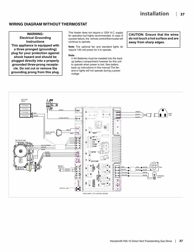
Hampton® H35-10 Direct Vent Freestanding Gas Stove | 37
37| installation
This heater does not require a 120V A.C. supply for operation but highly recommended. In case of a power failure, the remote control/thermostat will continue to operate.
Note: The optional fan and standard lights do require 120 volt power for it to operate.
CAUTION: Ensure that the wires do not touch a hot surface and are away from sharp edges.
WARNING: Electrical Grounding
InstructionsThis appliance is equipped with
a three pronged (grounding) plug for your protection against
shock hazard and should be plugged directly into a properly grounded three-prong recepta-cle. Do not cut or remove the
grounding prong from this plug.
Note: 4 AA Batteries must be installed into the back
up battery compartment however for this unit to operate when power is lost. See battery back up instructions in this manual The fan and or lights will not operate during a power outage.
WIRING DIAGRAM WITHOUT THERMOSTAT
RESETSWITCH
RESETSWITCH

38 | Hampton® H35-10 Direct Vent Freestanding Gas Stove
| 38 operating instructions
WIRING DIAGRAM WITH OPTIONAL THERMOSTAT
RESETSWITCH
Thermostat( Optional)(Millivolt)

Hampton® H35-10 Direct Vent Freestanding Gas Stove | 39
39| operating instructions
FIRST FIRE
The FIRST FIRE in your stove is part of the paint curing process. To ensure that the paint is properly cured, it is recommended that you burn your fireplace for at least four (4) hours the first time you use it with the fan on. When first operated, the unit will release an odour caused by the curing of the paint and the burning off of any oils remaining from manufactur-ing. Smoke detectors in the house may go off at this time. Open a few windows to ventilate the room for a couple of hours. The glass may require cleaning.
DO NOT ATTEMPT TO CLEAN THE GLASS WHILE IT IS STILL HOT!
Note: When the glass is cold and the appliance is lit, it may cause condensation and fog the glass. This condensation is normal and will disappear in a few minutes as the glass heats up.
DO NOT BURN THE APPLIANCE WITH-OUT THE GLASS FRONT IN PLACE.
During the first few fires, a white film may develop on the glass front as part of the cur-ing process. The glass should be cleaned or the film will bake on and become very difficult to remove. Use a non-abrasive cleaner and NEVER clean the glass while it is hot.
OPERATING INSTRUCTIONS
1) Read and understand these instructions before operating this appliance.
2) Check to see that all wiring is correct and en-closed to prevent possible shock.
3) Check to ensure there are no gas leaks.
4) Make sure the glass in the door frame is properly positioned. Never operate the appliance with the glass removed. Never strike the glass or slam the door shut.
5) Verify that the venting and cap are unobstructed.
6) Verify log placement. If the pilot cannot be seen when lighting the unit - the logs have been incorrectly positioned.
7) The unit should never be turned off, and on again without a minimum of a 60 second wait.
This remote control requires coding. See remote coding instructions for details.
NOTE: This appliance will operate with 4 AA back-up batteries installed (see Back-up Battery section for details) during power outages. Only the fan and light will not operate until power is restored. If the remote is misplaced, the unit can be shut off by flipping the main ON/OFF switch, located behind the front cover plate, to the OFF position.
IMPORTANT: The remote control system supplied with this appliance has several options for starting/operating the appliance, please read the remote control operating instructions (packed with remote control) to understand how to operate this remote system. You can download remote functions video with the QR code below..
OPERATION USING AN OP-TIONAL WALL THERMOSTAT
All Hampton stoves ship with a full function remote control as standard equipment. This allows for basic on/off function as well as the ability to operate as a thermostat. With the addition of an optional wall cradle (820-477-AWT available from an autho-rized dealer) the remote can reside on a wall and carry out all the functions of a typical millivolt wall thermostat as well as being able to control the fan speed, accent light and the flame height. This is the recommended procedure for operating the unit with a thermostatic set point.If a millivolt wall thermostat is required for bedroom installation or as preferred method of controlling the stove there are two options.
Option 1Wall thermostat and remote. Set the wall thermo-stat to the desired set point, then place the remote transmitter in either SMART or thermostatic mode with a set point 5 degrees above the set point on the wall thermostat. The burner will fire until the set point on the wall thermostat is satisfied. The
remote will remain connected and allow full control of all accessories.
Option 2Wall thermostat only. Divorce the remote hand held from the IFC by pressing the Red SW1 button on the IFC twice. Then operate the unit by setting the wall thermostat set point to the desired temperature. ** Please be aware that in this configuration the accent light, flame height adjustment and fan will not be available.
Battery BackupTo operate the stove during a power outage or when power is not available.- Attach the backup battery pack to the 9v connector in the valve tray labeled “Battery”- Press the Red SW1 button on the IFC twice (each time you should get a three beeps in response) to put the unit into manual mode. Once this is complete the pilot will spark and ignite.- The stove can now be operated with the ON/OFF switch located on the front of the valve tray cover. The burner will remain lit until the switch is moved to the OFF position.

40 | Hampton® H35-10 Direct Vent Freestanding Gas Stove
| 40 operating instructions
IMPORTANT: The remote control system supplied with this appliance has several options for starting/operating the appliance using the power button and ON/OFF key on the hand held transmitter.
Prior to operating this appliance, please read the remote control operating instructions (packaged with remote control) to understand how to operate this remote control system. Option to download remote functions video with QR code below.
1. Ensure the main switch is in the ON position and/or the battery holder switch is in the Remote position.
2. Press and release the ON/OFF button on the remote handheld transmit-ter (see Diagram 2). An audible beep should be heard from the receiver.
4. The unit will turn on.
Note: The first try for ignition will last approximately 60 seconds. If there is no flame ignition (rectification) the board will stop sparking for approximately 35 seconds. After wait time , the board will start second try for ignition by sparking for approximately 60 seconds . If there is still no positive ignition the board will go into lock out.
The system will need to be reset as follows:
a) Wait 5 minutes - turn the system off by pressing the ON/OFF button on the remote.
b) After approximately 2 seconds turn on ON/OFF switch or press ON/OFF button if using optional remote.
c) Repeat step 2.
ON/OFF Button
SHUTDOWN PROCEDURE
1. Press the On/OFF button on the remote.
2. If service is to be performed- you must disconnect power and shut off gas to the unit.
Remote shown in Manual Mode on Hi
3. After approximately 4 seconds the spark ignition system will spark for 60 seconds to light the main burner.
LIGHTING PROCEDURE
Fan Operation:The optional fan can be operated by using the remote control supplied with this unit. See remote control instructions.
Note: In thermostat mode: When the appliance is turned on, the fan will not come on for the first 5 minutes (if fan is turned on). When the appliance is turned off the fan will not turn off for 12 minutes (if in on position)
Manual mode: Fan will turn on and off immediately using the remote control transmitter if the fan function is in the "on" position.
Continuous Pilot/Intermittent Pilot (CPI/IPI) selection
See remote control instructions for details.

Hampton® H35-10 Direct Vent Freestanding Gas Stove | 41
41| operating instructions
COPY OF THE LIGHTING PLATE INSTRUCTIONS
919-535
Part #: 919-535
Colours: Black on Grey, except for parts indicated as being Red.
Size: 100% w- 5.16" h- 10.3" Mar 25/15: Created decal
A) This appliance is equipped with an ignition device which automatically lights the pilot. Do not try to light the pilot by hand.B) BEFORE OPERATING smell all around the appliance area for gas. Be sure to smell next to the fl oor because some gas is heavier than air and will settle on the fl oor. WHAT TO DO IF YOU SMELL GAS
- Do not try to light any appliance.- Do not touch any electric switch, do not use any phone in your building.- Immediately call your gas supplier from a neighbours phone. Follow the gas supplier’s instructions.- If you cannot reach your gas supplier, call the fi re department.
C) Do not use this appliance if any part has been under water. Immediately call a qualifi ed service technician to inspect the appliance and replace any part of the control system and any gas control which has been underwater.A) Cet appareil est muni d’un dispositif d’allumage qui allume automatiquement la veilleuse. Ne tentez pas d’allumer la veilleuse manuellement. B) AVANT DE FAIRE FONCTIONNER, renifl ez tout autour de l’appareil pour déceler une odeur de gaz. Renifl ez près du plancher, car certains gaz sont plus lourds que l’air et peuvent s’accumuler au niveau du sol. QUE FAIRE SI VOUS SENTEZ UNE ODEUR DE GAZ : • Ne tentez pas d’allumer d’appareil • Ne touchez à aucun interrupteur; ne vous servez pas des téléphones se trouvant dans le bâtiment. • Appelez immédiatement votre fournisseur de gaz depuis un voisin. Suivez les instructions du fournisseur. • Si vous ne pouvez rejoindre le fournisseur, appelez le service incendie.C) N’utilisez pas cet appareil s’il a été plongé dans l’eau, même partiellement. Faites inspecter l’appareil par un tech-
nicien qualifi é et remplacez toute partie du système de contrôle et toute commande qui ont été plongés dans l’eau.
DO NOT REMOVE THIS INSTRUCTION PLATE
TO TURN OFF GAS APPLIANCE
This appliance must be installed in accordance with local codes, if any;if none, follow the National Fuel Gas Code, ANSI Z223.1/NFPA 54, or
Natural Gas and Propane Installation Codes, CSA B149.1.
CAUTION: Hot while in operation. Do not touch. Severe Burns may result. Due to high surface temperatures keep children, clothing and furniture, gasoline and other liquids having fl ammable vapors away. Keep burner and control compartment clean. See installation and operating instructions accompanying appliance.
WARNING: If you do not follow these instructions exactly, a fire or explosion may result causing property damage, personal injury or loss of life. Improper installation, adjustment, alteration, service or maintenance can cause injury or property damage. Refer to the owner’s information manual provided with this appliance. For assistance or additional information consult a qualified installer, service agency or gas supplier.AVERTISSEMENT. Quiconque ne respecte pas à la lettre les instructions dans la présente notice risque de déclencher un incendie ou une explosion entraînant des dommages, des blessures ou la mort.Tout défaut d'installation, d'ajustement, de modifi cation, de service ou d'entretien peut provo-quer des blessures ou des dommages matériels. Reportez-vous au manuel du propriétaire de l'information fournie avec cet appareil. Pour obtenir de l'aide ou des informations supplémen-taires consulter un installateur qualifi é, une agence de service ou fournisseur de gaz.
1) Ensure the Main switch is in the ON position and/or the battery holder switch is in the Remote position.2) Press and release the ON/OFF button on the remote handheld transmitter. An audible beep should be
heard from the receiver. 3) After approximately 4 seconds the spark ignition system will spark for 60 seconds to light the main burner.4) The unit will turn on.Note: The fi rst attempt to ignition will last approximately 60 seconds. If there is no fl ame ignition (rectifi ca-tion) the board will stop sparking for approximately 35 seconds. After this wait time, the board will start a second try for ignition by sparking for approximately 60 seconds. If there is still no positive ignition after the second attempt the board will go into lock out.The system will need to be reset as follows (after going into lock out mode): a) Wait 5 minutes - turn the system off by pressing the ON/OFF button on the remote. b) After approximately 2 seconds press the ON/OFF button again. c) Unit will repeat step 2.1) S’assurer que l’interrupteur principal est sur ON et/ou que l’interrupteur du support de piles est en posi-tion télécommande.2) Appuyer sur la touche ON/OFF de la télécommande et relâcher. Un bip se fera entendre depuis le récep-teur.3) Après environ 4 secondes, le système d'allumage produira des étincelles pendant 60 secondes pour al-lumer le brûleur principal.4) L'appareil s’allume.Remarque : Au premier allumage, le système tente d’allumer les fl ammes pendant 60 secondes. Si l’essai est infructueux, le système fait une pause de 35 secondes. C’est ce qu'on appelle l'étape de rectifi cation. Ce délai écoulé, le système tente à nouveau d'allumer les fl ammes en produisant des étincelles pendant 60 secondes. Si les fl ammes ne s’allument toujours pas, le système se met en mode verrouillage. Il faut alors le réinitialiser en suivant les étapes ci-dessous (pour le déverrouiller) : a) Attendre 5 minutes et éteindre l’appareil en appuyant sur la touche ON/OFF de la télécom-
mande. b) Attendre 2 secondes et appuyer encore une fois sur la touche ON/OFF. c) L'appareil répète l'étape 2.
1) Press the ON/OFF button on the remote.2) If service is to be performed–you must disconnect power and shut off gas to the unit.
1) Appuyer sur la touche ON/OFF de la télécommande.2) En cas d'entretien, débrancher l'alimentation électrique et couper le gaz.
LIGHTING INSTRUCTIONS
FOR YOUR SAFETY READ BEFORE LIGHTING

42 | Hampton® H35-10 Direct Vent Freestanding Gas Stove
| 42 operating instructions
PROFLAME II REMOTE CONTROL OPERATING INSTRUCTIONS
919-829 09.29.17
PROFLAME II REMOTE CONTROL OPERATING INSTRUCTIONS
WARNING: THE TRANSMITTER AND RECEIVER ARE RA‑DIO FREQUENCY DEVICES. PLACING THE RECEIVER IN OR NEAR METAL MAY SERVERELY REDUCE THE SIGNAL
The Proflame 2 Transmitter provides for controlling the following hearth appliance functions:1. Main Burner On/Off2. Main Burner flame modulation (6 levels)3. Choice of standing or intermittent pilot (CPI/IPI)4. Thermostat and Smart thermostat functions5. Accent light modulation (6 levels)**6. Split flow valve**7. Comfort Fan speed modulation (6 levels)**
** This feature is not available on all models.
IMPORTANT:The Proflame Transmitter 2 is an integrated part of the Proflame 2 System, which consists of these elements:• Proflame 2 Transmitter, to be used in conjunction with:• Integrated Fireplaces Control (Proflame 2 IFC)
The Proflame Transmitter uses a streamline design with a simple button layout and informative LCD display (Fig. 1). A Mode Key is provided to index between the features and a Thermostat Key is used to turn on/off or index through Thermostat functions (Fig. 1 & 2). Additionally, a Key Lock feature is provided (Fig. 22).
Figure 1: Proflame Transmitter
Figure 2: Transmitter LCD Display
TECHNICAL DATAREMOTE CONTROL
Supply Voltage 4.5V (three 1.5V AAA batteries)
Ambient temperature ratings
0 - 50oC (32 - 122oF)
Radio Frequency 315 MHZ
ATTENTION!
- Turn “OFF” the main gas supply of the appliance during installation or maintenance of the Receiver device.
- Turn “OFF” main gas supply to the appliance prior to removing or rein-serting the batteries.
- In case of remote control malfunction, turn off the IFC device using the "ON/OFF" main switch.
- For installation / maintenance, switch off the IFC device removing main power supply plug.
OPERATING PROCEDURE
Initializing the System for the first time
Power the receiver. Activate the procedure of the receiver address pro-gramming, see the receiver instruction (*). The Receiver will “beep” three (3) times to indicate that it is ready to synchronize with a Transmitter. Install the 3 AAA type batteries in the Transmitter battery bay, located on the base of the Transmitter. (fig. 3) With the batteries already installed in the Transmitter, push the On button. The Receiver will “beep” four times to indicate the Transmitter’s command is accepted and sets to the particular code of that Transmitter. The system is now initialized.
(*) The receiver may be independent or integral to the IFC hearth ap-pliance control module. The receiver instruction may not be indepen-dent when part of the IFC.
Figure 3: Battery Compartment
�
PRO
FLAM
E 2
TRAN
SMI
TTER
U
SE
ANDI
NST
AL L
The Proflame Remote Control System consists of three elements:
1. Proflame Transmitter.2. Proflame Receiver and a wiring harness to connect the Receiver to the gas valve, stepper motor and Fan Control Module.3. Proflame Fan Control Module (FCM)
The Proflame Transmitter uses a streamline design with a simple button layout and informative LCD display (Fig. 1). The Transmitter is powered by 3 AAA type batteries.A Mode Key is provided to Index between the features and a Thermostat Key is used to turn on/off or index through Thermostat functions (Fig. 1 & 2).
TRANsMITTER (Remote Control with LCD Display)
sysTEM DEsCRIpTIoN
Fig. 1: PROFLAME Transmitter.
Low battery alarmChild safety lock-out
RoomTemperature
Aux ON
Set PointTemperature/Level/State
Flame ON
Thermostat OFF/ON/SMART
Fan
Fig. 2: Transmitter LCD display.
Transmission
Turn on the Appliance
With the system OFF, press the ON/OFF Key on the Transmitter. The Transmitter display will show some other active Icons on the screen. At the same time the Receiver wil activate the appliance. A single “beep” from the Receiver will confirm reception of the command.
Turn off the Appliance
With the system ON, press the ON/OFF Key on the Transmitter. The Transmitter LCD display will only show the room temperature (Fig. 6). At the same time the Receiver will turn off the appliance. A single “beep” from the Receiver confirms reception of the command. Fig. 6: Remote Control display.
3 Positions Slider
Fig. 4: Proflame Receiver body.
PRG Key
Fig3: Battery compartment.
Fig. 4: Remote Control display in Farenheit. Fig. 5: Remote Control display in Celsius.
9957099_00_nero_mod_05-10-2011.i4 4 05/10/2011 8.36.38
1

Hampton® H35-10 Direct Vent Freestanding Gas Stove | 43
43| operating instructions
919-829 09.29.17
Figure 4: Remote Control dis-play in Farenheit.
Temperature indication Display
With the system in the "OFF" position, press the Thermostat Key and the Mode Key at the same time. Look at the LCD screen on the transmit-ter to verify that a C or F is visible to the right of the room temperature display (Figures 4 & 5).
Figure 5: Remote Control dis-play in Celsius.
Turn on the Appliance
With the system OFF, press the ON/OFF Key on the Transmitter. The Transmitter display will show some other active Icons on the screen. At the same time the Receiver wil ac-tivate the appliance. A single “beep” from the Receiver will confi rm recep-tion of the command.
Figure 6: Remote Control display
Remote-Flame Control
The profl ame has six (6) fl ame levels. With the system on, and the fl ame level at the maximum in the appliance, pressing the Down Arrow Key once will reduce the fl ame height by one step until the fl ame is turned off.The Up Arrow Key will increase the fl ame height each time it is pressed. If the Up Arrow Key is pressed while the system is on but the fl ame is off, the fl ame will come on in the high position. ( Fig. 7 & 8 ) A single “beep” will confi rm reception of the command.
Fig. 7
Fig. 8
Room Thermostat (Transmitter Operation)
The Remote Control can operate as a room thermostat. The thermostat can be set to a desired temperature to control the comfort level in a room.To activate this function, press the Thermostat Key (Fig. 1). The Lcd display on the Transmitter will change to show that the room thermostat is “ON” and the set temperature is now displayed (Fig. 9). To adjust the set temperature, press the Up or Down Arrow Keys until the desired set temperature is displayed on the LCD screen of the Transmitter.
Figure 9 Figure 10
Turn off the Appliance
With the system ON, press the ON/OFF Key on the Transmitter. The Transmitter LCD display will only show the room temperature (Fig. 6). At the same time the Receiver will turn off the appliance. A single “beep” from the Receiver confi rms reception of the command.
2

44 | Hampton® H35-10 Direct Vent Freestanding Gas Stove
| 44 operating instructions
919-829 09.29.17
Smart Thermostat (Transmitter Operation)
The Smart Thermostat function adjusts the fl ame height in accordance to the differencebetween the set point temperature and the actual room temperatures. As the roomtemperature gets closer to the set point the Smart Function will modulate the fl ame down.To activate this function, press the Thermostat Key (Fig. 1) until the word "SMART" appears tothe right of the temperature bulb graphic (Fig. 11).To adjust the set temperature, press the Up or Down Arrow Keys until the desidered settemperature is displayed on the LCD screen of the Transmitter (Fig. 12).Note. When Smart Thermostat is activated, manual fl ame height adjust-ment is disabled.
Figure 12Figure 11: Smart Flame Function
Fan Speed Control**
If the appliance is equipped with a hot air circulating fan, the speed of the fan can be controlled by the Profl ame system. The fan speed can be adjusted through six (6) speeds. To activate this function use the Mode Key (fi g.1) to index to the fan control icon (Fig. 13). Use the Up/Down Arrow Keys (fi g.1) to turn on, off or adjust the fan speed (fi g. 14). A single “beep”will confi rm reception of the command.
Figure 13 Figure 14
Remote dimmer control (Light)**
The auxiliary function controls the AUX power outlet by the dimmable light control. To activate this function use the Mode Key (fi g. 1) to index to the AUX icon (fi g. 15 & 16).The intensity of the output can be adjusted through six (6) levels. Use the Up/Down Arrow Keys (fi g.1) adjust the output level (fi g. 16). A single “beep” will confi rm reception of the command.
Note: This function is available only with the IFC Control Module.
Figure 15 Figure 16
Split Flow control**
The secondary burner is controlled by the split Flow. To activate this function use the Mode Key (fi g. 1) to index to the SPLIT FLOW mode icon (fi g. 17 & 18).Pressing the Up Arrow Key will activate the secondary burner. Pressing the Down Arrow Key will turn the secondary burner off. A single “beep” will confi rm the reception of the command.
Figure 17 Figure 18
3

Hampton® H35-10 Direct Vent Freestanding Gas Stove | 45
45| operating instructions
919-829 09.29.17
Continous Pilot/Intermittent Pilot (CPI/IPI) selection
With the system in "OFF" position press the Mode Key (fi g. 1) to index to the CPI mode icon (fi g. 19 & 20).Pressing the Up Arrow Key will activate the Continous Pilot Ignition mode (CPI). Pressing the Down Arrow Key will return to IPI. A single “beep” will confi rm the reception of the command.
Figure 19 Figure 20
KEY LOCKThis function will lock the keys to avoid unsupervised operation.To activate this function, press the MODE and UP Keys at the same time (fi g. 21).To de-activate this function, press the MODE and UP Keys at the same time.
Figure 21
LOW BATTERY POWER DETECTIONTransmitter
The life span of the remote control batteries depends on various factors: quality of the batteries used, the number of ignitions of the appliance, the number of changes to the room thermostat set point, etc.When the Transmitter batteries are low, a Battery Icon will appear on the LCD display of the Transmitter (Fig. 22) before all battery power is lost. When the batteries are replaced this Icon will disappear.
Figure 22
4

46 | Hampton® H35-10 Direct Vent Freestanding Gas Stove
| 46 maintenance
Top View of pilot flame
MAINTENANCE INSTRUCTIONS
1) Always turn off the valve before cleaning. For relighting, refer to lighting instructions. Keep the burner and control compartment clean by brushing and vacuuming at least once a year. When cleaning the logs, use a soft clean paint brush as the logs are fragile and easily dam-aged.
CAUTION: ANY SAFETY SCREEN OR GUARD REMOVED FOR SERV-ICING AN APPLIANCE MUST BE REPLACED PRIOR TO OPERATING THE APPLIANCE.
Top View of pilot flame
Incorrect flame pattern will have small, probably yellow flames, not coming into proper contact with the rear of the burner or thermopile.
NORMAL OPERATING SOUNDS OF GAS APPLIANCES
It is possible that you will hear some sounds from your gas appliance. This is perfectly normal due to the fact that there are various gauges and types of steel used within your appliance. Listed below are some examples. All are normal operating sounds and should not be considered as defects in your appliance.
Blower: Hampton® gas appliances use high tech blowers to push heated air farther into the room. It is not unusual for the fan to make a "whirring" sound when ON. This sound will increase or decrease in volume depending on the speed setting of your fan speed control.
Burner Tray: The burner tray is positioned directly under the burner tube(s) and logs and is made of a different gauge material from the rest of the firebox and body. Therefore, the varying thicknesses of steel will expand and contract at slightly different rates which can cause "ticking" and "cracking" sounds. You should also be aware that as there are tempera-ture changes within the unit these sounds will likely re-occur. Again, this is normal for steel fireboxes.
Blower Thermodisc: When this thermally activated switch turns ON it will create a small "clicking" sound. This is the switch contacts closing and is normal.
Pilot Flame: While the pilot flame is on it can make a very slight "whisper" sound.
Gas Control Valve: As the gas control valve turns ON and OFF, a dull clicking sound may be audible, this is normal operation of a gas regulator or valve.
Unit Body/Firebox: Different types and thicknesses of steel will expand and contract at different rates resulting in some "cracking" and "ticking" sounds will be heard throughout the cycling process.
WARNING: CHILDREN AND ADULTS SHOULD BE ALERTED TO THE HAZARDS OF HIGH SURFACE TEMPERATURE AND SHOULD STAY AWAY TO AVOID BURNS OR CLOTH-ING IGNITION. YOUNG CHILDREN SHOULD BE CAREFULLY SUPER-VISED WHEN THEY ARE IN THE SAME ROOM AS THE APPLIANCE.
8) Each time the appliance is lit, it may cause con-densation and fog the glass. This condensation and fog is normal and will disappear in a few minutes as the glass heats up.
Never operate the appliance without the glass properly secured in place.
9) Periodically check the pilot flames. Correct flame pattern has three strong blue flames: 1 flowing around the thermopile and 1 around the thermocouple, and 1 flowing across the rear of the burner (it does not have to be touching the burner).
Note: If you have an incorrect flame pattern, contact your Hampton® dealer for further instructions.
2) Clean glass (never when unit is hot), appliance, and door with a damp cloth. Never use an abrasive cleaner.
3) The heater is finished in a porcelain finish or with a heat resistant paint and should only be refinished with heat resistant paint (not with wall paint).
Never use an abrasive cleaner on the porcelain finish as it may scratch the surface.
4) Make a periodic check of burner for proper posi-tion and condition. Visually check the flame of the burner periodically, making sure the flames are steady; not lifting or floating. If there is a problem, call a qualified service person.
5) CAUTION: Label all wires prior to disconnec-tion when servicing controls. Wiring errors can cause improper and dangerous operation.
6) The appliance and venting system must be inspected before use, and at least annually, by a qualified field service person, to ensure that the flow of combustion and ventilation air is not obstructed.
During the annual service call, the burners should be removed from the burner tray and cleaned. Replace the embers but do not block the pilot.
7) Keep the area near the appliance clear and free from combustible materials, gasoline, and other flammable vapours and liquids.
DO NOT USE THIS APPLIANCE IF ANY PART HAS BEEN UNDER WA-TER. IMMEDIATELY CALL A QUALI-FIED SERVICE TECHNICIAN TO INSPECT THE APPLIANCE AND TO REPLACE ANY PART OF CONTROL SYSTEM AND ANY GAS CONTROL WHICH HAS BEEN UNDER WATER.
CLOTHING OR OTHER FLAMMA-BLE MATERIAL SHOULD NOT BE PLACED ON OR NEAR THE APPLI-ANCE.

Hampton® H35-10 Direct Vent Freestanding Gas Stove | 47
47| maintenance
To remove fan:
1) Unplug or disconnect power source to stove.
2) Remove the 6 screws holding the access panel in place.
FAN MAINTENANCE
If your fan requires maintenance or replacement, access to the fan is through the rear access panel on the back of the unit. NOTE: the unit MUST NOT be operated without the fan access panel securely in place and correctly sealed.
IMPORTANT: These fans collect a lot of dust from within your home. Ensure you maintain these fan motors on a regular basis by vacuum-ing out the fan squirrel cages, around the motor, and around the grills on the back of the stove.
IMPORTANTDisconnect power supply
before servicing
GENERAL VENT MAINTENANCE
Conduct an inspection of the venting system semi-annually. Recommended areas to inspect as follows:
1) Check the Venting System for corrosion in areas that are exposed to the elements. These will appear as rust spots or streaks, and in extreme cases, holes. These components should be replaced immediately.
2) Remove the Cap, and shine a flashlight down the Vent. Remove any bird nests, or other foreign material.
3) Check for evidences of excessive condensa-tion, such as water droplets forming in the inner liner, and subsequently dripping out the joints, Continuous condensation can cause corrosion of caps, pipe, and fittings. It may be caused by having excessive lateral runs, too many elbows, and exterior portions of the system being ex-posed to cold weather.
4) Inspect joints, to verify that no pipe sections or fittings have been disturbed, and consequently loosened. Also check mechanical supports such as Wall Straps, or plumbers' tape for rigidity.
LOG REPLACEMENT
The unit should never be used with broken logs. Turn off the gas valve and allow the unit to cool before opening door to carefully remove the logs. The pilot light generates enough heat to burn someone. If for any reason a log should need replacement, you must use the proper replacement log. The position of these logs must be as shown in the diagram under Log Installation.
Note: Improper positioning of logs may create carbon build-up and will alter the unit’s performance which is not covered under warranty.
GLASS REPLACEMENT
Your stove is supplied with high temperature, 5 mm Neoceram ceramic glass that will withstand the highest heat that your unit will produce. In the event that you break your glass by impact, purchase your replacement door from an authorized Hampton® dealer only, and follow our step-by-step instructions for replacement.
1) Lift off the Cast Top.
2) Open the 2 latches of the Glass Front.
3) Lift the Glass Front Assembly up.
WARNING: Electrical Grounding Instructions
This appliance is equipped with a three pronged (grounding) plug for your protection against shock hazard and should be plugged directly into a properly grounded three-prong receptacle. Do not cut or remove the grounding prong from this plug.
3) Unclip the black and red wires from the fan motor.
4) Lift fan off of the 2 pins, tip back and pull through rear panel. Do not tear or damage the flex pipe when removing the fan. Disconnect the green ground lug wire from the fan as soon as you can reach it.
Latches
4) Remove the glass and replace with the new glass.
5) Replace the door and Cast Top.
Replacement Part # 940-324/P Glass
WARNING: Do not operate appliance with glass panel removed, cracked or broken. Replacement of the glass should be done by a licensed or quali-fied service person.
Note: Wearing gloves will protect your hands while handling glass.
Rear Access Panel
>
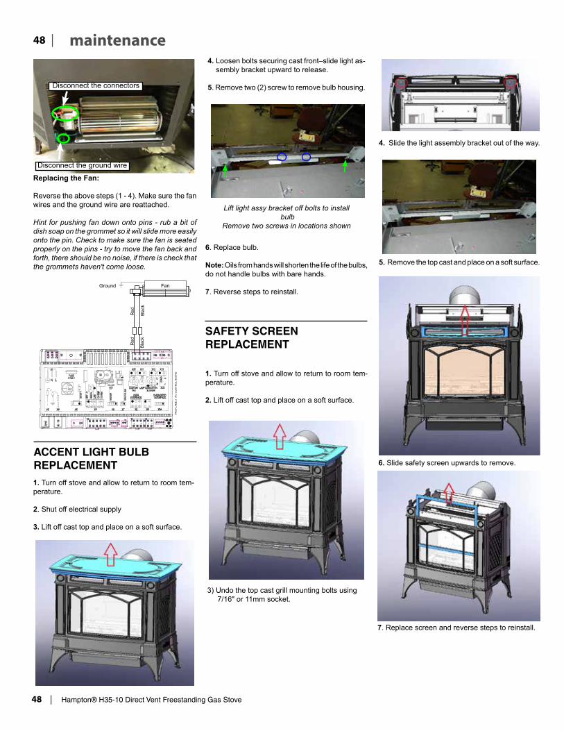
48 | Hampton® H35-10 Direct Vent Freestanding Gas Stove
| 48 maintenance
Replacing the Fan:
Reverse the above steps (1 - 4). Make sure the fan wires and the ground wire are reattached.
Hint for pushing fan down onto pins - rub a bit of dish soap on the grommet so it will slide more easily onto the pin. Check to make sure the fan is seated properly on the pins - try to move the fan back and forth, there should be no noise, if there is check that the grommets haven't come loose.
Disconnect the ground wire
Disconnect the connectors
ACCENT LIGHT BULB REPLACEMENT1. Turn off stove and allow to return to room tem-perature.
2. Shut off electrical supply
3. Lift off cast top and place on a soft surface.
4. Loosen bolts securing cast front–slide light as-sembly bracket upward to release.
5. Remove two (2) screw to remove bulb housing.
Lift light assy bracket off bolts to install bulb
Remove two screws in locations shown
6. Replace bulb.
Note: Oils from hands will shorten the life of the bulbs,do not handle bulbs with bare hands.
7. Reverse steps to reinstall.
3) Undo the top cast grill mounting bolts using 7/16" or 11mm socket.
6. Slide safety screen upwards to remove.
SAFETY SCREEN REPLACEMENT
1. Turn off stove and allow to return to room tem-perature.
2. Lift off cast top and place on a soft surface.
4. Slide the light assembly bracket out of the way.
5. Remove the top cast and place on a soft surface.
7. Replace screen and reverse steps to reinstall.
Red
Red

Hampton® H35-10 Direct Vent Freestanding Gas Stove | 49
49| maintenance
12) Carefully lift the burner tray assembly out of the unit to remove.
13) Replace with new valve assembly and reverse steps to reinstall. .
To remove valve from valve assembly, continue.
14) Disconnect the red, green and yellow wires from the stepper motor as shown in the picture
REMOVING VALVE
If your valve requires maintenance or replacement, use the following instructions:
Note: Always close off the gas supply before removing the valve.
1) If optional fan is installed, disconnect power source to stove.
2) Open the access panel and remove the valve cover plate.
3) Disconnect gas line to stove.
4) Disconnect 3/8" NPT pipe from 90o elbow on valve.
5) Disconnect the two (2) switch wires from valve.
6) Lift off the Cast Top and lift out the front door.
7) Remove the cast front. (See page 13 for instruc-tions).
8) Remove the glass front assembly by opening the the 2 latches.
9) Carefully remove the logs, embers and rockwool.
10) Remove burner (see diagram below).
Note: Use a magnetic type screwdriver if possible.
11) Remove all 18 screws holding the burner tray assembly in place.
INSTALLING VALVE ASSEMBLY
1) To install a new valve assembly, reverse instruc-tions for removing valve. See assembly steps 1-11.
2) Check for leaks and manifold pressure. See Gas Pressure Test instructions.
3) To reinstall valve, reverse instructions for remov-ing valve assembly, steps 14-20.
Disconnect the ignition wires from IFC, connected to the valve
15) Remove two (2) ignition cables from the IFC.
16) Remove pilot nut with an 11 mm wrench.
17) Remove valve to orifice nut with a 13/16" wrench.
18) Remove inlet pipe with pipe wrench. Note orientation of 90o elbow.
19) Remove two (2) phillips head M5 screws on each side of the valve.
20) Remove valve and remove gas out 90o brass fitting. Note orientation of fitting.

50 | Hampton® H35-10 Direct Vent Freestanding Gas Stove
| 50 parts listMAIN ASSEMBLY
1) 730-550 Burner Tube Assembly NG/LP2) Firebox Assembly3) 770-066F Pressure Relief Frame3a) W260280 Pressure Relief Frame Gasket4) Transition Box Assembly6) 740-542 Front Door Assembly7) 743-160 Front Brick Inlay8) 740-548 Relief Door Assembly9) 743-513 Rear Panel Assembly10) 740-532 Upper Air Passage Assembly11) Base Assembly12) 560-517/P Fan Assembly13) N/A Lower Air Passage Assembly14) 743-201 Cast Top Charcoal Grey 743-205 Cast Top Timberline Brown 743-207 Cast Top Seaside Sand15) 743-211 Cast Left Charcoal Grey 743-215 Cast Left Timberline Brown 743-217 Cast Left Seaside Sand16) 743-221 Cast Right Charcoal Grey 743-225 Cast Right Timberline Brown 743-227 Cast Right Seaside Sand
Part # Description
19) 743-231 Cast Front Charcoal Grey 743-235 Cast Front Timberline Brown 743-237 Cast Front Seaside Sand20) 743-271 Top Cast Grill Charcoal Brown 743-275 Top Cast Grill Timberline Brown 743-277 Top Cast Grill Seaside Sand21) 743-100 Safety Screen23) 743-241 Cast Leg Charcoal Grey (each) 743-245 Cast Leg Timberline Brown (each) 743-247 Cast Leg Seaside Sand (each)24) 940-324/P Replacement Glass/Includes Gasket
Part # Description
21
3a24

Hampton® H35-10 Direct Vent Freestanding Gas Stove | 51
51| parts list
BURNER & LOG ASSEMBLY
13) 730-550 Burner Assembly - NG/LP19) Air Shutter21) 743-574/P Valve Assembly NG 743-576/P Valve Assembly LP31) Valve Heat Shield39) 743-056 Valve Access Door45) 743-006 Valve Cover47) 911-085 Novasit Valve LP 885 SIT 911-084 Novasit Valve -NG 885 48) 948-042 Hinge Spring Black49) 910-246 On/Off Switch52) 911-006 Pilot Assy-SIT-3 flame-NG 911-007 Pilot Assy-SIT-3 flame-LP67) 730-041 Pilot Holder68) W840470 Pilot Assembly Gasket75) 402-935 Log Set 740-572 Ember Package83) 400-090 Brick Clip84) 740-901 Rustic Brown Brick Panels 740-902 Old Town Red Brick Panels** 911-010 Stepper Motor NG** 911-011 Stepper Motor LP** 910-100 Novasit Pilot Orifice - NG** 910-101 Novasit Pilot Orifice -LP** 911-039 Novasit Pilot Hood 2 way** 911-137 Pilot Hood Clip** 911-037 Flame Sensor ** 911-038 Flame Electrode** 904-240 Burner Orifice #37-NG** 904-390 Burner Orifice #52-LP** 904-529 5/32*Allen Key - Pilot Orifice** 936-170 Burner Orifice Gasket W840470 Pilot Assembly Gasket (Each)** 911-174 IFC Integrated Fireplace Control Proflame 2** 911-175 Hand Held Remote Control GT MFL 0.584.042** 911-179ASM 120 Volt Power Cord Assembly** 911-173 Valve/Remote Wiring Harness 584.924** 911-177 4 Position Wire Harness Fan & Light Proflame II** 911-178 2 Position Wire Harness On/Off Switch** 910-998 Halogen Light Socket Assembly** 910-997 Halogen Light Bulb 120 Volt/20 Watt/ JCD Bi-Pin/Gy6.35 ** 910-331/P Blower Motor Only with Squirrel Cage** 911-093 10 Foot Extension Cord** 911-027 Battery Holder W/9V Snap in 4 AA Batteries** 911-242 Reset Switch 945F Simpson Duravent Strater Collar W8442051- Starter Collar Gasket - Outer W260108 - Starter Collar Gasket - Inner
*Note: Not available as a replacement part.
Part # Description
BRICK PANEL SET
83
83
84 >
48

52 | Hampton® H35-10 Direct Vent Freestanding Gas Stove
| 52 warrantyLimited Lifetime Warranty FPI Fireplace Products International Ltd. (for Canadian customers) and Fireplace Products U.S., Inc. (for U.S. customers) (collectively referred to herein as “FPI”) extends this Limited Lifetime Warranty to the original purchaser of this appliance provided the product remains in the original place of installation. The items covered by this limited warranty and the period of such coverage is set forth in the table below. Some conditions apply (see below). The policy is not transferable, amendable or negotiable under any circumstances.
Indoor Gas Products Part Supplier Labor
Coverage Warranty Coverage Parts and Labor Lifetime 5 years 2 years 1 year Warranty (Years)
Firebox and Heat Exchanger 3 Steel Burner Tube 3 Glass Thermal breakage only 3 All Surrounds/Inlays Finishes 3 Brick Panels/Log sets/Ceramic Burners 3
All Castings 3 Valve assembly and all gas control components, (Pilot assembly, flame sensors, Spark Electrode, Pilot Tubing, Orifices, Thermocouple, Thermopile)
2
All Other Electrical components,(Ignition Control Boards, Wiring, Switches, Blowers, Blower Control Module, Battery Pack, Remote Control Systems)
2
Enamel Panels 1 Venting/Venting Components 1 All Stainless steel surrounds 1 All Firebox Media (Crystals, Firebeads, Volcanic, Ceramic & Spa Stones)
1
All hardware 1 Mesh/Glass Safety Barriers 1 Accent Light Bulbs 1 Glass (Crazing) 1
Conditions: Warranty protects against defect in manufacture or FPI factory assembled components only, unless herein specified otherwise. Any part(s) found to be defective during the warranty period as outlined above will be repaired or replaced at FPI’s option through an accredited distributor, dealer or pre-approved and assigned agent provided that the defective part is returned to the distributor, dealer or agent for inspection if requested by FPI. Alternatively, FPI may at its own discretion fully discharge all of its obligations under the warranty by refunding the verified purchase price of the product to the original purchaser. The purchase price must be confirmed by the original Bill of Sale. The authorized selling dealer, or an alternative authorized FPI dealer if pre-approved by FPI, is responsible for all in-field diagnosis and service work related to all warranty claims. FPI is not responsible for results or costs of workmanship of unauthorized FPI dealers or agents in the negligence of their service work.
Revision Date: December 2016 Regency Gas Products Warranty

Hampton® H35-10 Direct Vent Freestanding Gas Stove | 53
53| warranty
At all times FPI reserves the right to inspect reported complaints on location in the field claimed to be defective prior to processing or authorizing of any claim. Failure to allow this upon request will void the warranty. All warranty claims must be submitted by the dealer servicing the claim, including a copy of the Bill of Sale (proof of purchase by you). All claims must be complete and provide full details as requested by FPI to receive consideration for evaluation. Incomplete claims may be rejected. Unit must be installed according to all manufacturers’ instructions as per the manual. All Local and National required codes must be met. The installer is responsible to ensure the unit is operating as designed at the time of installation. The original purchaser is responsible for annual maintenance of the unit, as outlined in the owner’s manual. As outlined below, the warranty may be voided due to problems caused by lack of maintenance. Repair/replacement parts purchased by the consumer from FPI after the original coverage has expired on the unit will carry a 90 day warranty, valid with a receipt only. Any item shown to be defective will be repaired or replaced at our discretion. No labor coverage is included with these parts Exclusions: This Limited Lifetime Warranty does not extend to paint, rust or corrosion of any kind due to a lack of maintenance or improper venting, combustion air provision, corrosive chemicals (i.e. chlorine, salt, air, etc.), door or glass gasketing. Malfunction, damage or performance based issues as a result of environmental conditions, location, chemical damages, downdrafts, installation error, installation by an unqualified installer, incorrect chimney components (including but not limited to cap size or type), operator error, abuse, misuse, use of improper fuels , lack of regular maintenance and upkeep, acts of God, weather related problems from hurricanes, tornados, earthquakes, floods, lightning strikes/bolts or acts of terrorism or war, which result in malfunction of the appliance are not covered under the terms of this Limited Lifetime Warranty. FPI has no obligation to enhance or modify any unit once manufactured (i.e. as products evolve, field modifications or upgrades will not be performed on existing appliances). This warranty does not cover dealer travel costs for diagnostic or service work. All labor rates paid to authorized dealers are subsidized, pre-determined rates. Dealers may charge homeowner for travel and additional time beyond their subsidy. Any unit showing signs of neglect or misuse will not be covered under the terms of this warranty policy and may void this warranty. This includes units with rusted or corroded fireboxes which have not been reported as rusted or corroded within three (3) months of installation/purchase. Units which show evidence of being operated while damaged, or with problems known to the purchaser and causing further damages will void this warranty. Units where the serial no. has been altered, deleted, removed or made illegible will void this warranty. Minor movement, expansion and contraction of the steel is normal and is not covered under the terms of this warranty. Freight damages for products or parts are not covered under the terms of the warranty. Products made or provided by other manufacturers and used in conjunction with the FPI appliance without prior authorization from FPI may void this warranty.
Revision Date: December 2016 Regency Gas Products Warranty

54 | Hampton® H35-10 Direct Vent Freestanding Gas Stove
| 54 warranty
Limitations of Liability: The original purchaser’s exclusive remedy under this warranty, and FPI’s sole obligation under this warranty, express or implied, in contract or in tort, shall be limited to replacement, repair, or refund, as outlined above. IN NO EVENT WILL FPI BE LIABLE UNDER THIS WARRANTY FOR ANY INCIDENTAL OR CONSEQUENTIAL COMMERCIAL DAMAGES OR DAMAGES TO PROPERTY. TO THE EXTENT PERMITTED BY APPLICABLE LAW, FPI MAKES NO EXPRESS WARRANTIES OTHER THAN THE WARRANTY SPECIFIED HEREIN. THE DURATION OF ANY IMPLIED WARRANTY IS LIMITED TO DURATION OF THE EXPRESSED WARRANTY SPECIFIED ABOVE. IF IMPLIED WARRANTIES CANNOT BE DISCLAIMED, THEN SUCH WARRANTIES ARE LIMITED IN DURATION TO THE DURATION OF THIS WARRANTY. Some U.S. states do not allow limitations on how long an implied warranty lasts, or allow exclusion or limitation of incidental or consequential damages, so the above limitations or exclusions may not apply to you. Customers located outside the U.S. should consult their local, provincial or national legal codes for additional terms which may be applicable to this warranty. How to Obtain Warranty Service: Customers should contact the authorized selling dealer to obtain warranty service. In the event the authorized selling dealer is unable to provide warranty service, please contact FPI by mail at the address listed below. Please include a brief description of the problem and your address, email and telephone contact information. A representative will contact you to make arrangements for an inspection and/or warranty service. Canadian Warrantor: FPI Fireplace Products International Ltd. 6988 Venture St. Delta, British Columbia Canada, V4G 1H4
U.S. Warrantor: Fireplace Products U.S., Inc. PO Box 2189 PMB 125 Blaine, WA United States, 98231
Or contact the Regency Customer Care Centre at 1-800-442-7432 (phone) / 604-946-4349 (fax) Product Registration and Customer Support: Thank you for choosing a Regency Fireplace. Regency strives to be a world leader in the design, manufacture, and marketing of hearth products. To provide the best support for your product, we request that you complete a product registration form at http://www.regency-fire.com/Customer-Care/Warranty-Registration.aspx within ninety (90) days of purchase.
Revision Date: December 2016 Regency Gas Products Warranty

Hampton® H35-10 Direct Vent Freestanding Gas Stove | 55
55| warranty
Product Registration and Customer Support:
Thank you for choosing a Regency Fireplace. Regency strives to be a world leader in the design, manufacture, and marketing of hearth products. To provide the best support for your product, we request that you complete a product registration form found on our Web Site under Customer Care within ninety (90) days of purchase.
For purchases made in CANADA or the UNITED STATES: http://www.regency-fire.com/Customer-Care/Warranty-Registration.aspx
For purchases made in AUSTRALIA: http://www.regency-fire.com.au/Customer-Care/Warranty-Registration.aspx
You may also complete the warranty registration form below to register your Regency Fireplace Product and mail and/or fax it back to us, and we will register the warranty for you. It is important you provide us with all the information below in order for us to serve you better.
Warranty Registration Form (or Register online immediately at the above Web Site):
Warranty Details
Serial Number (required):
Purchase Date (required) (mm/dd/yyyy):
Product Details
Product Model (required):
Dealer Details
Dealer Name (required):
Dealer Address:
Dealer Phone #:
Installer:
Date Installed (mm/dd/yyyy):
Your Contact Details (required)
Name:
Address:
Phone:
Email:
For purchases made in CANADA:
FPI Fireplace Products International Ltd. 6988 Venture St. Delta, British Columbia Canada, V4G 1H4
For purchases made in the UNITED STATES:
Fireplace Products U.S., Inc. PO Box 2189 PMB 125 Blaine, WA United States, 98231
Phone: 604-946-5155 Fax: 604-946-4349
Phone: 604-946-5155 Fax: 604-946-4349
For purchases made in AUSTRALIA:
Fireplace Products Australia Pty Ltd 1- 3 Conquest Way Hallam, VIC Australia, 3803
Phone: +61 3 9799 7277 Fax: +61 3 9799 7822
For fireplace care and tips and answers to most common questions please visit our Customer Care section on our Web Site. Please feel free to contact your selling dealer if you have any questions about your Regency product.


Hampton® H35-10 Direct Vent Freestanding Gas Stove | 57
57| notes

58 | Hampton® H35-10 Direct Vent Freestanding Gas Stove
| 58 notes

H35-10 Product Video
Printed in CanadaHampton® and AstroCap™ are trademarks of FPI Fireplace Products International Ltd.© Copyright 2018, FPI Fireplace Products International Ltd. All rights reserved.
Installer: Please complete the following information
Dealer Name & Address: ______________________________________________
___________________________________________________________________
Installer: ___________________________________________________________
Phone #: ___________________________________________________________
Date Installed: ______________________________________________________
Serial No.: __________________________________________________________