SpaceFibre CODEC: Use of the TLK2711-SP -...
36
1 SpaceFibre CODEC: Use of the TLK2711-SP Steve Parkes 1 , Chris McClements, Martin Suess 2 1 Space Technology Centre, University of Dundee 2 ESA, ESTEC, The Netherlands
Transcript of SpaceFibre CODEC: Use of the TLK2711-SP -...

1
SpaceFibre CODEC:
Use of the TLK2711-SP
Steve Parkes1, Chris McClements, Martin Suess2 1Space Technology Centre, University of Dundee
2ESA, ESTEC, The Netherlands

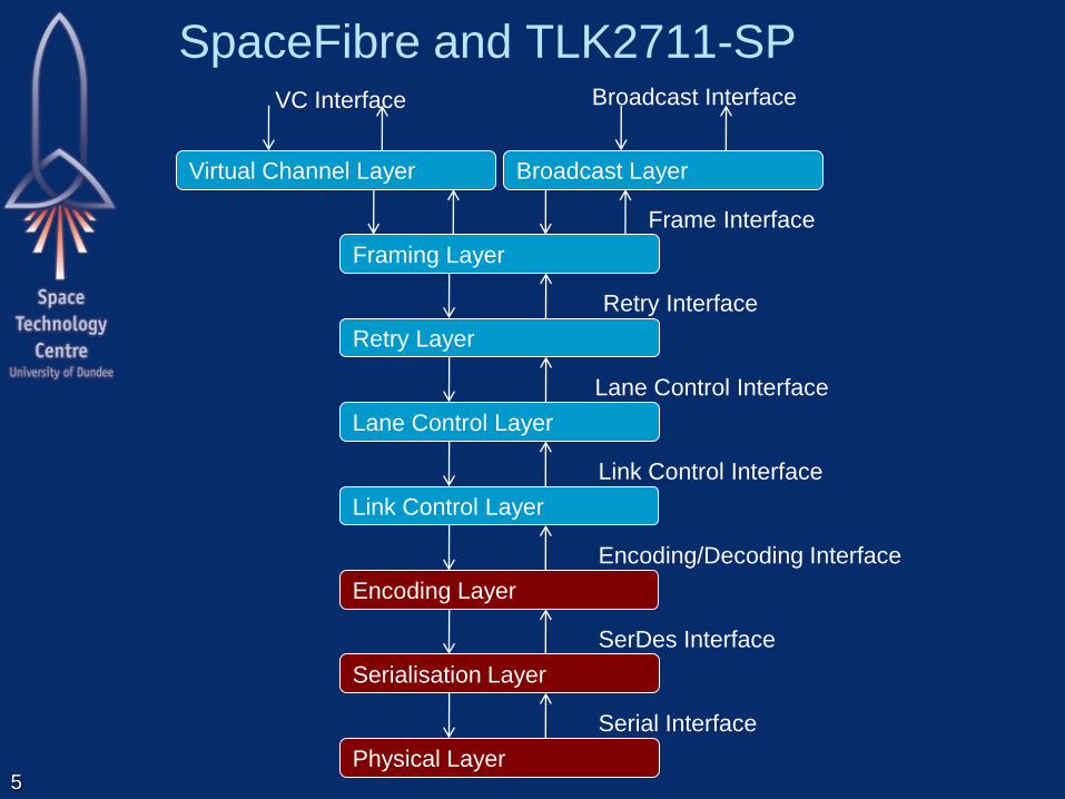
SpaceFibre Overview
2
Retry Interface
Retry Layer
Encoding/Decoding Interface
Encoding Layer
SerDes Interface
Serialisation Layer
Virtual Channel Layer
VC Interface
Serial Interface
Physical Layer
Lane Control Interface
Lane Control Layer
Link Control Interface
Link Control Layer
Broadcast Interface
Broadcast Layer
Framing Layer
Frame Interface

SpaceFibre Layers
Virtual Channel:
– Quality of service and flow control
Broadcast:
– broadcasts short messages across network
Framing:
– Frames information to be sent over link
– Scrambles SpaceWire packet data
Retry:
– Recovers from transient and persistent errors
3

SpaceFibre Layers
Lane Control:
– Runs several SpaceFibre links in parallel
– Provides higher data throughput and redundancy
with graceful degradation
Link Control:
– Link initialisation, error detection and re-
initialisation
Encoding/Decoding:
– Encodes data into symbols for transmission
Serialisation:
– Serialises SpaceFibre symbols
Physical:
– Fibre optic or copper medium.
4
SpaceFibre and TLK2711-SP
5
Retry Interface
Retry Layer
Encoding/Decoding Interface
Encoding Layer
SerDes Interface
Serialisation Layer
Virtual Channel Layer
VC Interface
Serial Interface
Physical Layer
Lane Control Interface
Lane Control Layer
Link Control Interface
Link Control Layer
Broadcast Interface
Broadcast Layer
Framing Layer
Frame Interface
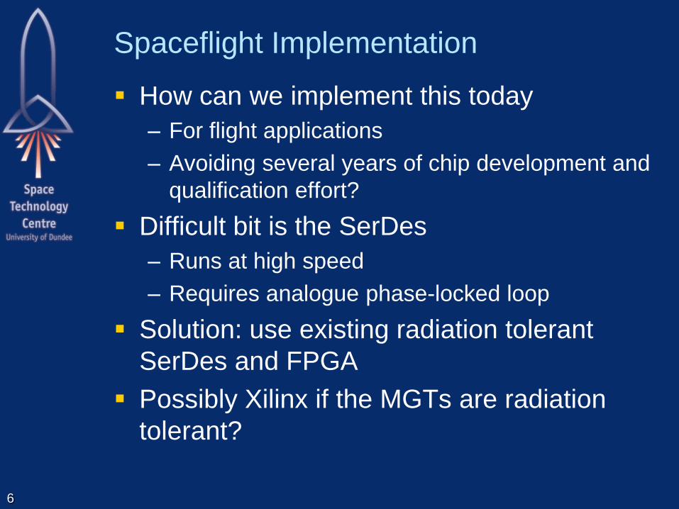
Spaceflight Implementation
How can we implement this today
– For flight applications
– Avoiding several years of chip development and
qualification effort?
Difficult bit is the SerDes
– Runs at high speed
– Requires analogue phase-locked loop
Solution: use existing radiation tolerant
SerDes and FPGA
Possibly Xilinx if the MGTs are radiation
tolerant?
6

Flight Implementation
7
FPGA
SerDes
Serialisation
Encoding
Link Control
Lane Control
Retry
Framing
Virtual Channels
Broadcast Channel
Application
Logic

TLK2711-SP
TLK2711-SP
– Radiation tolerant SerDes
– Includes 8B/10B encoder/decoder
– Runs at 2.5 Gbits/s
2 Gbit/s actual data rate
– Combined with a radiation tolerant FPGA
– Can be used to implement radiation tolerant
SpaceFibre interface
Problem: incompatible with draft SpaceFibre
standard!
SpaceFibre specification modified to be able
to use this device
Also possible to use other SerDes devices 8
9
INIT_1
INIT_2
STANDBY
LOS
8B/10B
ENCODER
SERIALISER
DRIVER RECEIVER
DE-SERIALISER
8B/10B
DECODER
SYMBOL
SYNC
RECEIVE
ELASTIC
BUFFER
CLOCK
RECOVERY
MUX
MUX
LINK LAYER
ORDERED SET
EXTRACTION
LINK
INITIALISATION
AND STANDBY
CONTROLLER
RECEIVE
SYNC
STATE MCH.
LINK
SYNC
SerDes Interface
Link Interface
MUX
IDLE
MUX
SKIP
SKIP
INSERTION
COUNTER
Symbol
Synchronisation
Serialisation/
De-Serialisation
Link Initialisation and
Standby Management
Data Rate Adjustment
8B/10B Encode/Decode
8B/10B
ENCODER
8B/10B
DECODER
MUX
Line Driver/Receiver
Serial Interface
10, 20, 40
8+1, 16+2 ,
32+4
32+4 32+4
32+4
32+4
32+4 32+4
Word Synchronisation
Serial Loop-Back
10, 20, 40
8+1, 16+2, 32+4
WORD SYNC
Encoding/Decoding Interface
MUX
IDLE
ERROR
DECODER
Link Control Layer
Encoding Layer
Serialisation Layer
MUX Parallel Loopback
INVERTER
LoS
Inv Rx
Inv Rx
LoS
Rx Inversion
LINK ACTIVE

10
8B/10B Coding
Zero DC bias:
– same number of ones and zeros
10-bit symbols representing
– 8-bit data codes
– Some control codes, K-codes
– Codes use
5 ones and 5 zeros
4 ones and 6 zeros
6 ones and 4 zeros
– Characters with different number of 1s and 0s
have two possible codes to preserve DC bias

11
8B/10B Coding
Ensures sufficient bit transitions for clock
recovery
– No more than 5 consecutive ones or zeros
All characters encoded with 10-bits giving
constant bit and character rates, simplifying
transmitter and receiver
Unused codes can be used to detect link
errors

12
8B/10B Encoder
5B/6B
Encoder
3B/4B
Encoder
Running
Disparity
5 ls-bits 6-bits
3 ms-bits 4-bits
8-bit Data
Input
Control/Data
Input (K/D)
10-bit
Encoded
Output 5B/6B Disparity
3B/4B Disparity

13
Part of 5B/6B Encoding Table
Input Output
Data Input Data bits 43210
(EDCBA)
Current Running
Disparity -ve
abcdei
Current Running
Disparity +ve
abcdei
D00.y 00000 100111 011000
D01.y 00001 011101 100010
D02.y 00010 101101 010010
D03.y 00011 110001
D04.y 00100 110101 001010
D05.y 00101 101001
D06.y 00110 011001
D07.y 00111 111000 000111
D08.y 01000 111001 000110
D09.y 01001 100101
D10.y 01010 010101
14
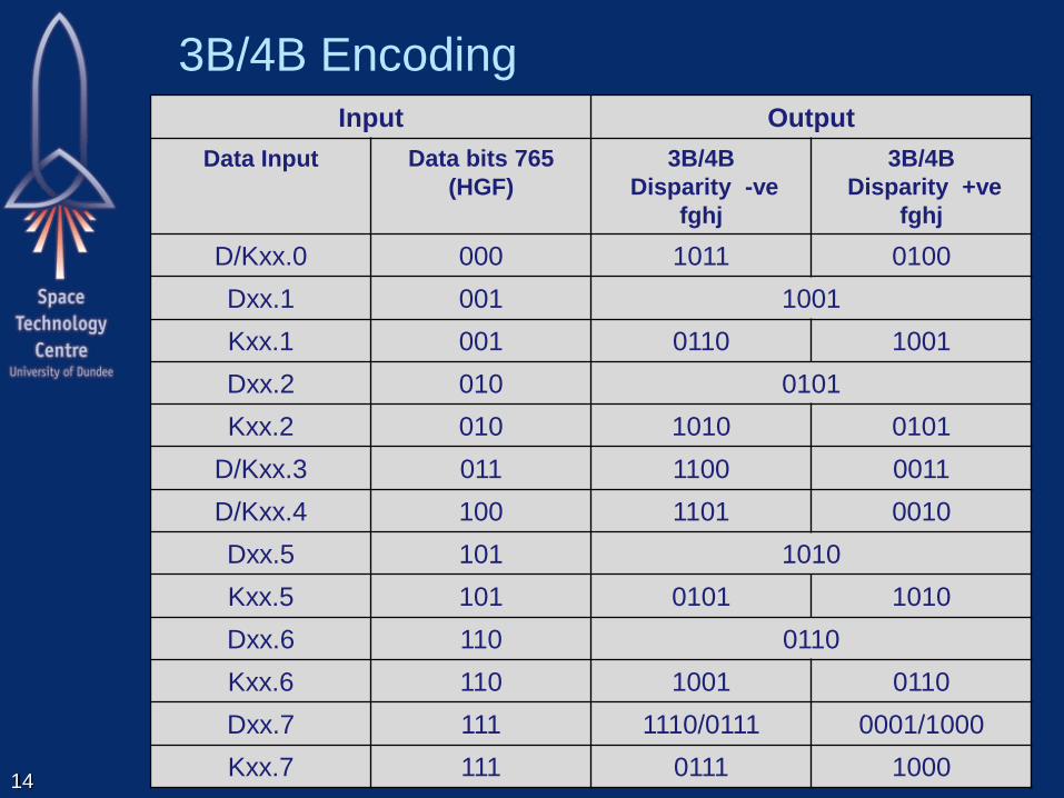
3B/4B Encoding
Input Output
Data Input Data bits 765
(HGF)
3B/4B
Disparity -ve
fghj
3B/4B
Disparity +ve
fghj
D/Kxx.0 000 1011 0100
Dxx.1 001 1001
Kxx.1 001 0110 1001
Dxx.2 010 0101
Kxx.2 010 1010 0101
D/Kxx.3 011 1100 0011
D/Kxx.4 100 1101 0010
Dxx.5 101 1010
Kxx.5 101 0101 1010
Dxx.6 110 0110
Kxx.6 110 1001 0110
Dxx.7 111 1110/0111 0001/1000
Kxx.7 111 0111 1000

15
8B/10B Control (K) Codes
Input Output
Special Character
Name
Current Running
Disparity -ve
Current Running Disparity
+ve
K28.0 001111 0100 110000 1011
K28.1 001111 1001 110000 0110
K28.2 001111 0101 110000 1010
K28.3 001111 0011 110000 1100
K28.4 001111 0010 110000 1101
K28.5 001111 1010 110000 0101
K28.6 001111 0110 110000 1001
K28.7 001111 1000 110000 0111
K23.7 111010 1000 000101 0111
K27.7 110110 1000 001001 0111
K29.7 101110 1000 010001 0111
K30.7 011110 1000 100001 0111
16
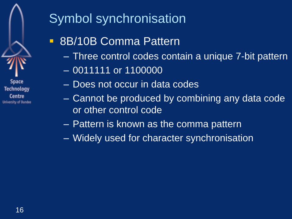
Symbol synchronisation
8B/10B Comma Pattern
– Three control codes contain a unique 7-bit pattern
– 0011111 or 1100000
– Does not occur in data codes
– Cannot be produced by combining any data code
or other control code
– Pattern is known as the comma pattern
– Widely used for character synchronisation
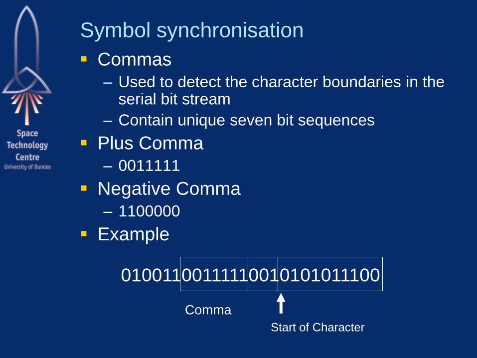
Symbol synchronisation
Commas – Used to detect the character boundaries in the
serial bit stream
– Contain unique seven bit sequences
Plus Comma – 0011111
Negative Comma – 1100000
Example
01001100111110010101011100
Comma
Start of Character

TLK2711-SP Transmitter
18
MUX
PRBS
Generator
TXP
TXN
BIAS PRE
Controls:
PLL, Bias, RX,
TX
TESTEN
ENABLE
To RX
18-b
it R
eg
iste
r TXD0-7
TKLSB
TXD8-15
TKMSB
LOOPEN
TX
DA
TA
LO
OP
EN
PRBSEN
PR
BS
EN
MUX Parallel
to Serial
Clock
Synthesiser TXCLK
SY
NC
LK
8B
/10
B
En
co
de
r
8B
/10
B
En
co
de
r

TLK2711-SP Receiver
19
RXP
RXN
LO
OP
EN
TX
DA
TA
Serial to
Parallel MU
X
PRBS
Verifier
PR
BS
EN
1
8-b
it R
egis
ter RXD0-7
RXD8-15
RKMSB
RKLSB
MU
X
Signal Detect
(LOS)
8B
/10
B
Decoder
8B
/10
B
Decoder
DE
MUX
MU
X Interpolator &
Clock
Recovery
SY
NC
LK
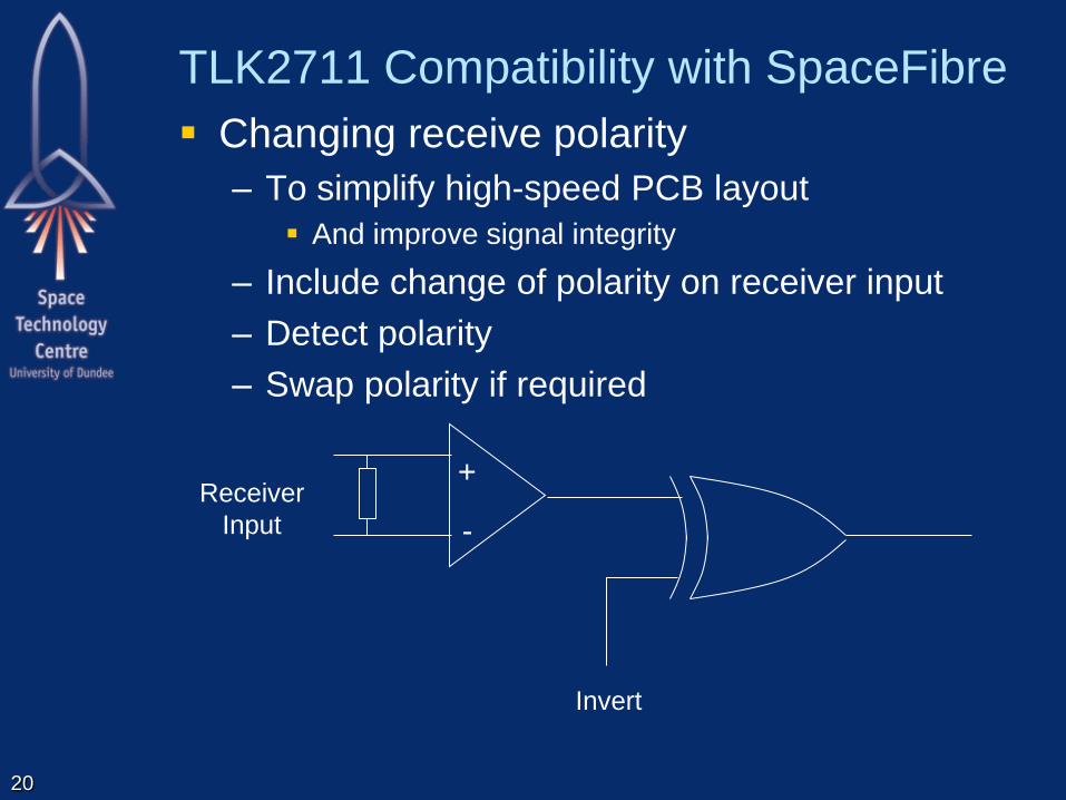
TLK2711 Compatibility with SpaceFibre
Changing receive polarity
– To simplify high-speed PCB layout
And improve signal integrity
– Include change of polarity on receiver input
– Detect polarity
– Swap polarity if required
20
Invert
+
-
Receiver
Input

TLK2711 Compatibility with SpaceFibre
Bit stream inversion
– TLK2711 does not support bit inversion
– Bit inversion is useful to help PCB layout
– SpaceFibre makes bit inversion mandatory for
new devices
– But permits legacy devices like TLK2711 to not
implement bit inversion
Detecting inversion
– INIT1 and IDLE control words have valid bitwise
inverse symbols
– Can then detect if direct or inverse INIT1’s being
received
– If inverse, change polarity of receiver
21
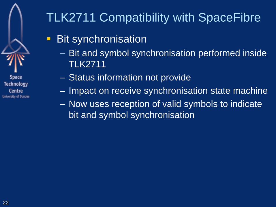
TLK2711 Compatibility with SpaceFibre
Bit synchronisation
– Bit and symbol synchronisation performed inside
TLK2711
– Status information not provide
– Impact on receive synchronisation state machine
– Now uses reception of valid symbols to indicate
bit and symbol synchronisation
22

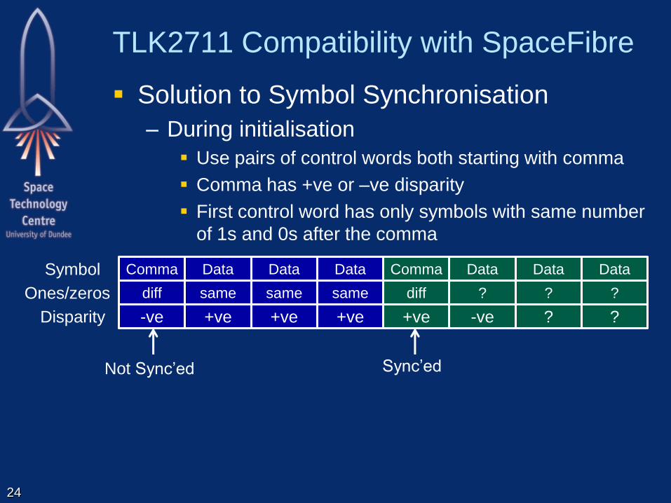
TLK2711 Compatibility with SpaceFibre
Symbol synchronisation
– Does not support symbol synchronisation on
negative disparity commas
– Link might never synchronise, depending on data
being sent
23
diff
Comma
-ve
diff
Data
+ve
diff
Data
-ve
diff
Data
+ve
Not Sync’ed
diff
Comma
-ve +ve
diff
Data
same
Data
-ve
same
Data
-ve Disparity
Ones/zeros
Symbol
Not Sync’ed
TLK2711 Compatibility with SpaceFibre
Solution to Symbol Synchronisation
– During initialisation
Use pairs of control words both starting with comma
Comma has +ve or –ve disparity
First control word has only symbols with same number
of 1s and 0s after the comma
24
same
Data
+ve
same
Data
+ve
same
Data
+ve
diff
Comma
+ve
?
Data
-ve
?
Data
?
?
Data
?
diff
Comma
-ve Disparity
Ones/zeros
Symbol
Sync’ed Not Sync’ed

TLK2711 Compatibility with SpaceFibre
Solution to Symbol Synchronisation
– During initialisation
Polarity is not known
INIT1 and IDLE control words have valid bitwise inverse
symbols
These bitwise inverse symbols are chosen to also have
same number of 1s and 0s
So if bit stream is inverted can still synchronise
25
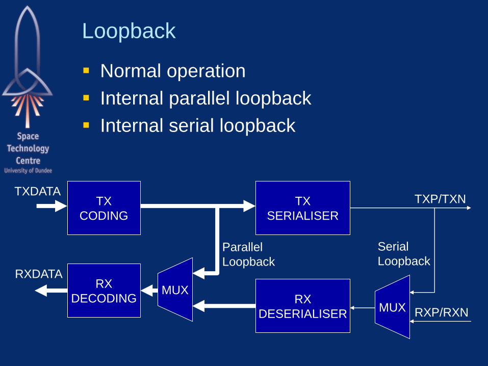
Loopback
Normal operation
Internal parallel loopback
Internal serial loopback
TX
CODING
TX
SERIALISER
RX
DECODING RX
DESERIALISER
MUX
MUX
TXDATA
RXDATA
Parallel
Loopback
TXP/TXN
RXP/RXN
Serial
Loopback

TLK2711 Compatibility with SpaceFibre
Parallel loopback
– Not implemented in TLK2711
– It does provide serial loopback
– SpaceFibre makes parallel loopback optional
– Serial loopback is mandatory
27
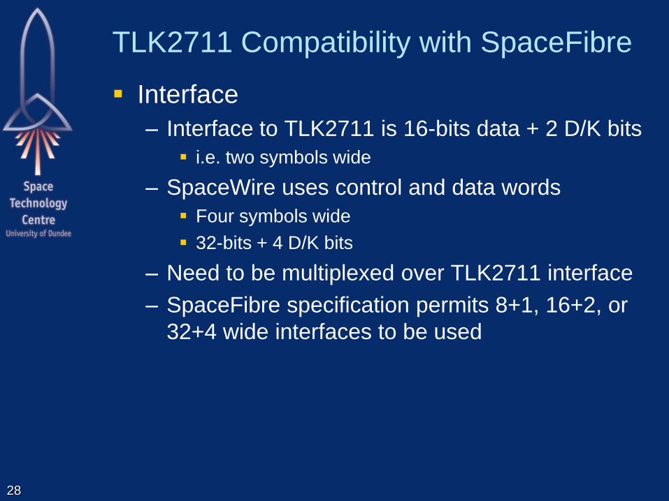
TLK2711 Compatibility with SpaceFibre
Interface
– Interface to TLK2711 is 16-bits data + 2 D/K bits
i.e. two symbols wide
– SpaceWire uses control and data words
Four symbols wide
32-bits + 4 D/K bits
– Need to be multiplexed over TLK2711 interface
– SpaceFibre specification permits 8+1, 16+2, or
32+4 wide interfaces to be used
28

TLK2711 Compatibility with SpaceFibre
Error indication
– TLK2711 indicates error detected by receiver by
output of a K0.0 code
– Which is not a valid K-code
– Decoder needed to decode this K-code into an
error signal
29
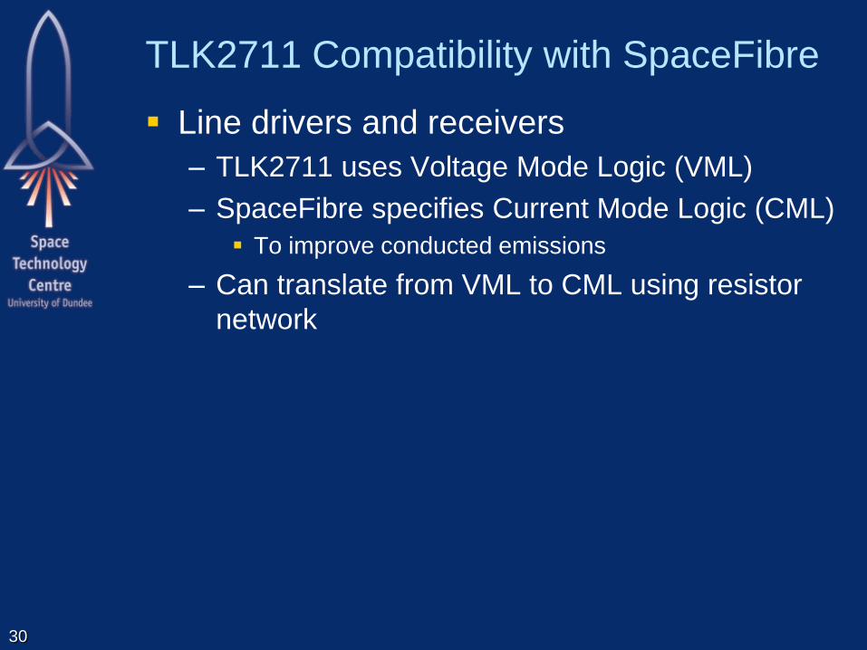
TLK2711 Compatibility with SpaceFibre
Line drivers and receivers
– TLK2711 uses Voltage Mode Logic (VML)
– SpaceFibre specifies Current Mode Logic (CML)
To improve conducted emissions
– Can translate from VML to CML using resistor
network
30
31
INIT_1
INIT_2
STANDBY
LOS
8B/10B
ENCODER
SERIALISER
DRIVER RECEIVER
DE-SERIALISER
8B/10B
DECODER
SYMBOL
SYNC
RECEIVE
ELASTIC
BUFFER
CLOCK
RECOVERY
MUX
MUX
LINK LAYER
ORDERED SET
EXTRACTION
LINK
INITIALISATION
AND STANDBY
CONTROLLER
RECEIVE
SYNC
STATE MCH.
LINK
SYNC
MUX
IDLE
MUX
SKIP
SKIP
INSERTION
COUNTER
8B/10B
ENCODER
8B/10B
DECODER
MUX
10, 20, 40
8+1, 16+2 ,
32+4
32+4 32+4
32+4
32+4
32+4 32+4
10, 20, 40
8+1, 16+2, 32+4
WORD SYNC
MUX
IDLE
ERROR
DECODER
Symbol
Synchronisation
8B/10B Encode/Decode
Word Synchronisation
Encoding Layer
MUX
Link Initialisation and
Standby Management
Data Rate Adjustment
Link Control Layer
Parallel Loopback
INVERTER
LoS
Inv Rx
Inv Rx
LoS
Serialisation/
De-Serialisation
Line Driver/Receiver
Serial Loop-Back
Serialisation Layer
Rx Inversion
Link Interface
SerDes Interface
Serial Interface
Encoding/Decoding Interface
LINK ACTIVE

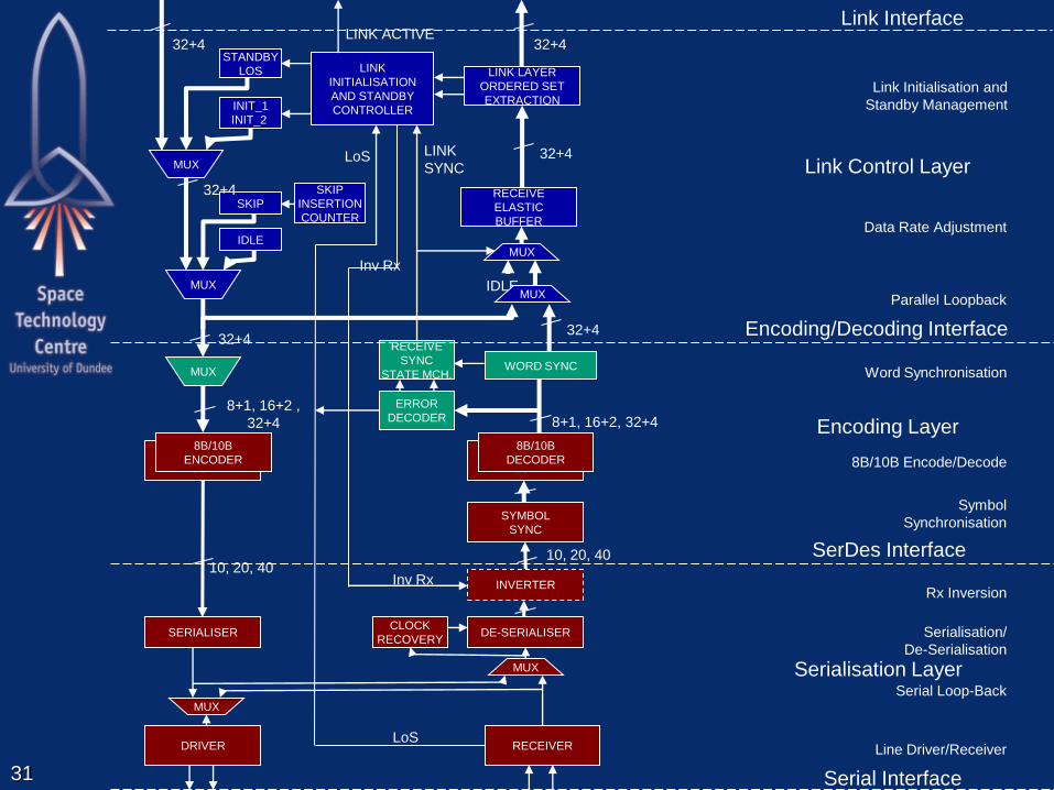
Revised SpaceFibre Architecture
Interface to lower layers
– Compatible with different serialiser/de-serialiser
devices
– May be necessary to adapt specific device to this
common interface
Encoding/decoding interface
– Transfer control and data words
– Encoding
8B/10B encoding into groups of four symbols
– Decoding
Symbol synchronisation
8B/10B decoding
Word synchronisation to from control and data words
32
Conclusions
SpaceFibre designed to meet needs of future
spacecraft
– High data-rate
– Quality of service
– FDIR
TLK2711-SP is a radiation tolerant SerDes
– Which includes 8B/10B encoding/decoding
Can be used as lower level of SpaceFibre
Enables immediate implementation of flight
qualified SpaceFibre design
SpaceFibre specification modified to be able
to use TLK2711-SP 33

34

35
8B/10B Notation
7 6 5 4 3 2 1 0
H G F E D C B A
H G F E D C B A
H G F E D C B A
ms ls
D/K
D/K
D/K
Data/
Control
ASCII Character
8B/10B Notation
Sub-Blocks
Swap Sub-Blocks
Decimal values D/K XX Y
Notation D/KXX.Y

8B/10B Notation Examples
36
1 0 1 0 1 1 0 0
1 0 1 0 1 1 0 0
1 0 1 0 1 1 0 0
1 0 1 0 1 1 0 0
D
D
D
D 12 5
D12.5
1 0 1 1 1 1 0 0
1 0 1 1 1 1 0 0
1 0 1 1 1 1 0 0
1 0 1 1 1 1 0 0
K
K
K
K 28 5
K28.5