
SpaceFibre - SpaceWirespacewire.esa.int/WG/SpaceWire/SpW-WG-Mtg17-Proceedings/Docum… ·...
139
SpaceFibre Steve Parkes 1 , Albert Ferrer 2 , Martin Suess 3 1 Space Technology Centre, University of Dundee. UK 2 STAR-Dundee Ltd, UK 3 ESA, ESTEC, The Netherlands 1
Transcript of SpaceFibre - SpaceWirespacewire.esa.int/WG/SpaceWire/SpW-WG-Mtg17-Proceedings/Docum… ·...

SpaceFibre
Steve Parkes1, Albert Ferrer2,
Martin Suess3
1Space Technology Centre,
University of Dundee. UK 2STAR-Dundee Ltd, UK
3ESA, ESTEC, The Netherlands
1

Contents
SpaceFibre Requirements
SpaceFibre Use Cases
SpaceFibre Architecture
– Virtual channels
– Broadcast channels
– Data Framing
– Retry
– Lane control
– Lane
– Encoding/Decoding
– Serialisation
– Physical
2

SpaceFibre Requirements
Compatible with SpaceWire
– At the packet and network levels
High speed
– 2 Gbits/s now (2.5 Gbit/s signalling)
– 5 Gbits/s planned (6.5 Gbits/s signalling)
Very high speed
– Multiple lanes e.g. 4 lanes 8 Gbits/s
Flight quality components
Fibre and copper implementations
100 m optical fibre
5 m copper
Low mass cable
3

SpaceFibre Requirements
FDIR
– Fault detection
Parity/disparity
CRC
– Fault isolation
Galvanic isolation
Data framing – time containment
Virtual channels – bandwidth containment
– Fault recovery
Link level retry
Graceful degradation on lane failure
Babbling idiot protection
Error reporting
4

SpaceFibre Requirements
Support SOIS services
– Packet delivery
– Memory access
– Synchronisation / Time distribution
– Device discovery
– Test
Quality of Service
– Best Effort
– Assured
– Resource Reserved
– Guaranteed
5

SpaceFibre Use Cases -Functions
6
Payload
Payload
Payload
AOCS
Sensors
AOCS
Actuators
AOCS
Processing
Payload
Processing
Payload
Processing
Payload
Processing
Housekeeping
Processing
Payload
Control
Processing
Data
Compression
Mass
Memory
Telemetry
Encoding
Telecommand
Decoding
Sensors and Actuators Processing Functions
Data Storage and Compression
Off Spacecraft
Communications Sensor and Actuator
Bus/Network
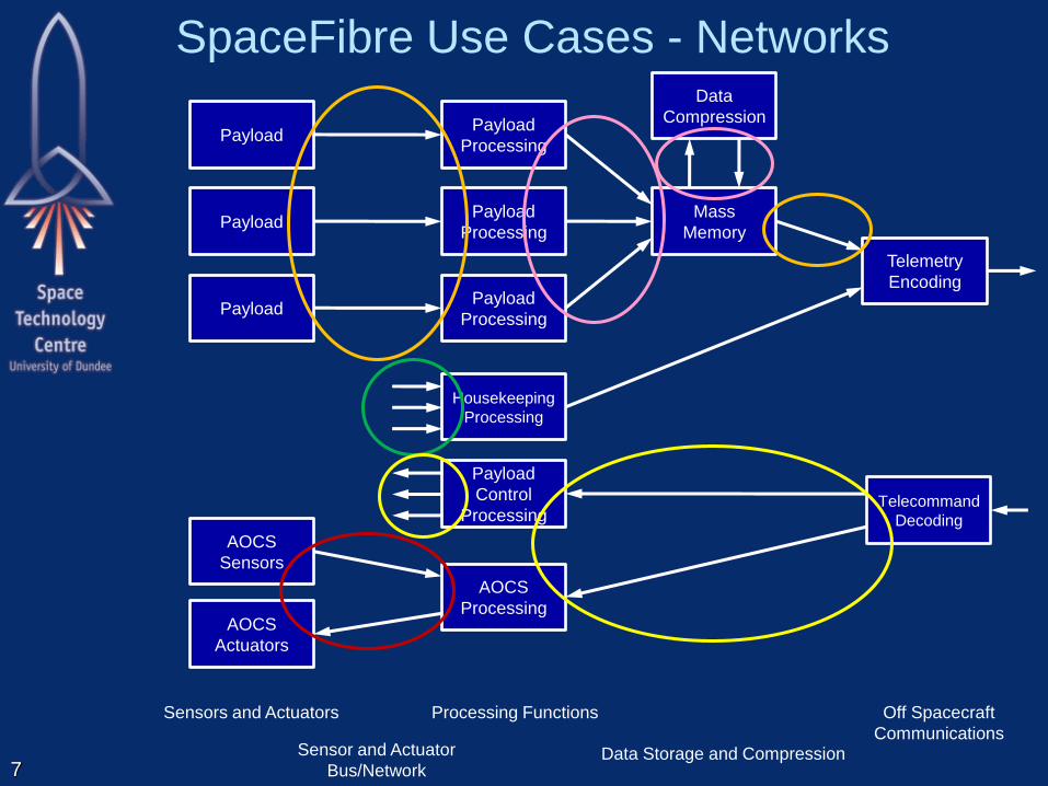
SpaceFibre Use Cases - Networks
7
Payload
Payload
Payload
AOCS
Sensors
AOCS
Actuators
AOCS
Processing
Payload
Processing
Payload
Processing
Payload
Processing
Housekeeping
Processing
Payload
Control
Processing
Data
Compression
Mass
Memory
Telemetry
Encoding
Telecommand
Decoding
Sensors and Actuators Processing Functions
Data Storage and Compression
Off Spacecraft
Communications Sensor and Actuator
Bus/Network

SpaceFibre Use Cases
Instrument data to mass-memory
– Point-to-point or virtual circuit
Instrument data to processor
– Point-to-point or virtual circuit
Mass-memory modules
– Network, controlled deterministically
Multiprocessor
– Network, asynchronous
Mass-memory to telemetry downlink
– Point-to-point
Housekeeping data gathering
– Network/bus, single master
8

SpaceFibre Use Cases
Telecommand to control processor
– Point-to-point or bus
Payload control
– Bus, discrete signals
AOCS/GNC
– Deterministic bus, discrete signals
Time distribution
– Time-codes, bus, separate wires
Synchronisation / Signalling
– Time-codes, bus, separate wires
9

SpaceFibre
Target SpaceFibre capabilities to the space
application
– Very high-speed
– Point-to-point
– Virtual Networks
– Virtual circuits
– Low latency signalling
FDIR
QoS
10

SpaceFibre Overview
11
Retry Interface
Retry Layer
Encoding/Decoding Interface
Encoding Layer
SerDes Interface
Serialisation Layer
Virtual Channel Layer
VC Interface
Serial Interface
Physical Layer
Lane Control Interface
Lane Control Layer
Lane Interface
Lane Layer
Broadcast Interface
Broadcast Layer
Framing Layer
Frame Interface

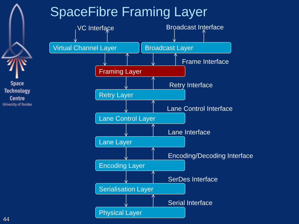
SpaceFibre Layers
Virtual Channel:
– Quality of service and flow control
Broadcast:
– broadcasts short messages across network
Framing:
– Frames information to be sent over link
– Scrambles SpaceWire packet data
Retry:
– Recovers from transient and persistent errors
12
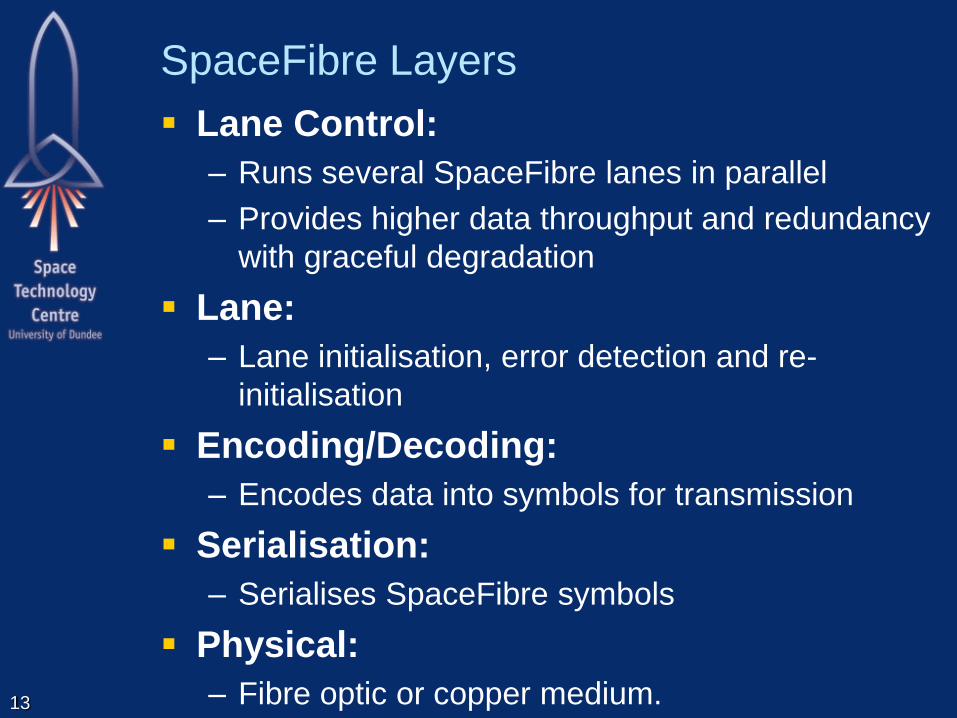
SpaceFibre Layers
Lane Control:
– Runs several SpaceFibre lanes in parallel
– Provides higher data throughput and redundancy
with graceful degradation
Lane:
– Lane initialisation, error detection and re-
initialisation
Encoding/Decoding:
– Encodes data into symbols for transmission
Serialisation:
– Serialises SpaceFibre symbols
Physical:
– Fibre optic or copper medium.
13

SpaceFibre Virtual Channel Layer
14
Retry Interface
Retry Layer
Encoding/Decoding Interface
Encoding Layer
SerDes Interface
Serialisation Layer
Virtual Channel Layer
VC Interface
Serial Interface
Physical Layer
Lane Control Interface
Lane Control Layer
Lane Interface
Lane Layer
Broadcast Interface
Broadcast Layer
Framing Layer
Frame Interface

15
VC,
TX_DATA
VC,
RX_DATA
Frame Interface
OUTPUT
BUS
VC,
RX_FCT
BC,
BR_SEQ#,
RX_BR_DATA
MEDIUM ACCESS
CONTROLLER
VC
BU
FF
ER
VC
BU
FF
ER
…
DE-MUX
VC
BU
FF
ER
VC
BU
FF
ER
…
TX FCT
CNTRL
RX FCT
DECODE
…
INPUT
BUS
OUTPUT
VCB
INPUT
VCB
VC Buffering
Flow Control
Quality of Service Control
Virtual Channel Layer
Broadcast Interface
VALIDATE
BROADCAST
SEQUENCE #
GENERATE
BROADCAST
SEQUENCE #
VC,
TX_FCT
BC,
BR_SEQ#,
TX_BR_DATA
BC RX_BR
DATA
BR
SEQ# BC TX_BR
DATA
BR
SEQ#
Broadcast Validation
Virtual Channel Interface
Broadcast
Interface
Broadcast Layer
SEGMENTATION REASSEMBLY Segmentation

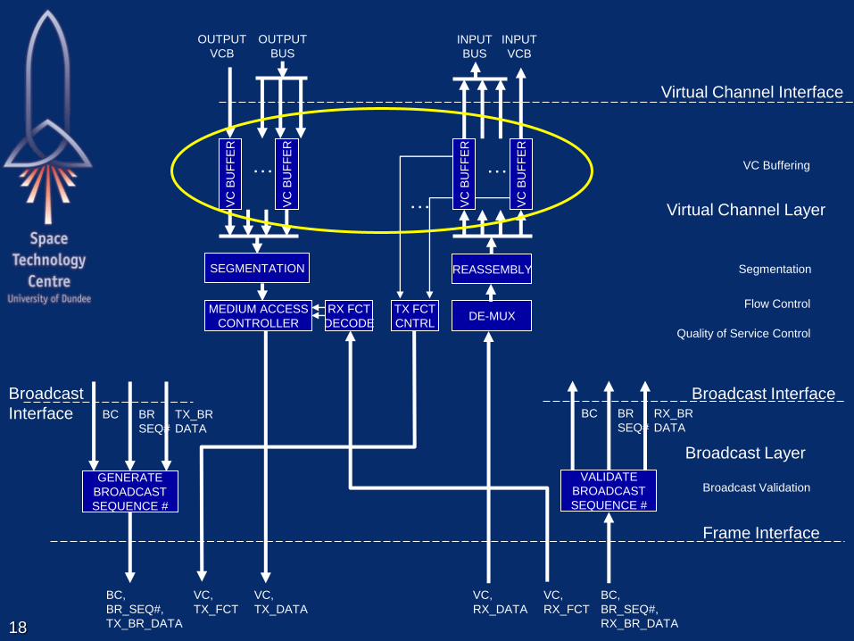
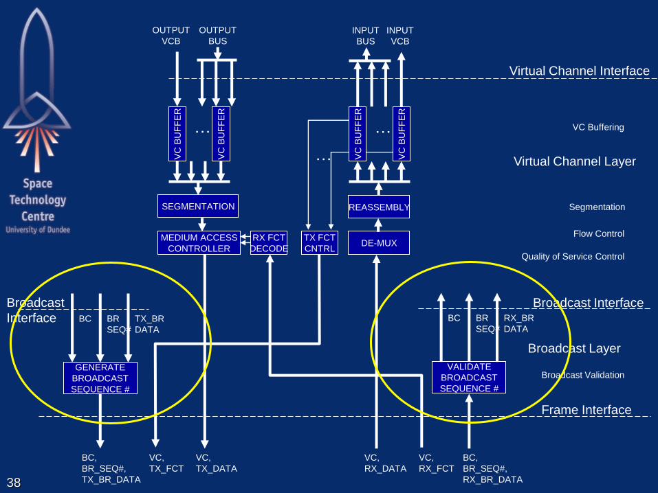
SpaceFibre Virtual Channels
Virtual Channel Interface
– Used to send and receive SpaceWire packets
– Comprises a number of virtual channel buffers
Output VCBs for sending SpaceWire packets
Input VCBs for receiving SpaceWire packets
Conceptual FIFO type interface
Accepts SpaceWire N-Chars (data + EOP/EEP)
– Application
Loads packet information sequentially into VCB
Addressing and routing is identical to SpaceWire
16

Virtual Channels
VC sends when
– Source VC buffer has data to send
– Destination VC buffer has space in buffer
– QoS for VC results in highest precedence
A SpW packet flowing through one VC does
not block another packet flowing through
another VC 17
VC1
VC2
VC3
M
A
C
VC1
VC2
VC3
D
E
M
U
X
18
VC,
TX_DATA
VC,
RX_DATA
Frame Interface
OUTPUT
BUS
VC,
RX_FCT
BC,
BR_SEQ#,
RX_BR_DATA
MEDIUM ACCESS
CONTROLLER
VC
BU
FF
ER
VC
BU
FF
ER
…
DE-MUX
VC
BU
FF
ER
VC
BU
FF
ER
…
TX FCT
CNTRL
RX FCT
DECODE
…
INPUT
BUS
OUTPUT
VCB
INPUT
VCB
VC Buffering
Flow Control
Quality of Service Control
Virtual Channel Layer
Broadcast Interface
VALIDATE
BROADCAST
SEQUENCE #
GENERATE
BROADCAST
SEQUENCE #
VC,
TX_FCT
BC,
BR_SEQ#,
TX_BR_DATA
BC RX_BR
DATA
BR
SEQ# BC TX_BR
DATA
BR
SEQ#
Broadcast Validation
Virtual Channel Interface
Broadcast
Interface
Broadcast Layer
SEGMENTATION REASSEMBLY Segmentation

SpaceFibre Virtual Channels
Virtual channel buffering
– VCBs buffer SpaceWire packets
– Output VCB
Buffers data before it is sent
– Output VCB must contain
A full frame of data (256 N-Chars)
Or an EOP / EEP
Before it is put forward for arbitration and sending
– Inputs VCBs
Holds at least one full data frame
Application can read data at its leisure
– Without affecting the network
19
20
VC,
TX_DATA
VC,
RX_DATA
Frame Interface
OUTPUT
BUS
VC,
RX_FCT
BC,
BR_SEQ#,
RX_BR_DATA
MEDIUM ACCESS
CONTROLLER
VC
BU
FF
ER
VC
BU
FF
ER
…
DE-MUX
VC
BU
FF
ER
VC
BU
FF
ER
…
TX FCT
CNTRL
RX FCT
DECODE
…
INPUT
BUS
OUTPUT
VCB
INPUT
VCB
VC Buffering
Flow Control
Quality of Service Control
Virtual Channel Layer
Broadcast Interface
VALIDATE
BROADCAST
SEQUENCE #
GENERATE
BROADCAST
SEQUENCE #
VC,
TX_FCT
BC,
BR_SEQ#,
TX_BR_DATA
BC RX_BR
DATA
BR
SEQ# BC TX_BR
DATA
BR
SEQ#
Broadcast Validation
Virtual Channel Interface
Broadcast
Interface
Broadcast Layer
SEGMENTATION REASSEMBLY Segmentation
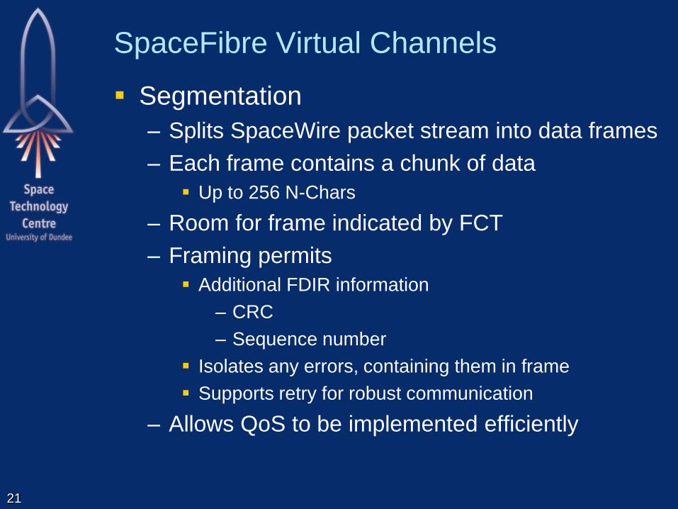
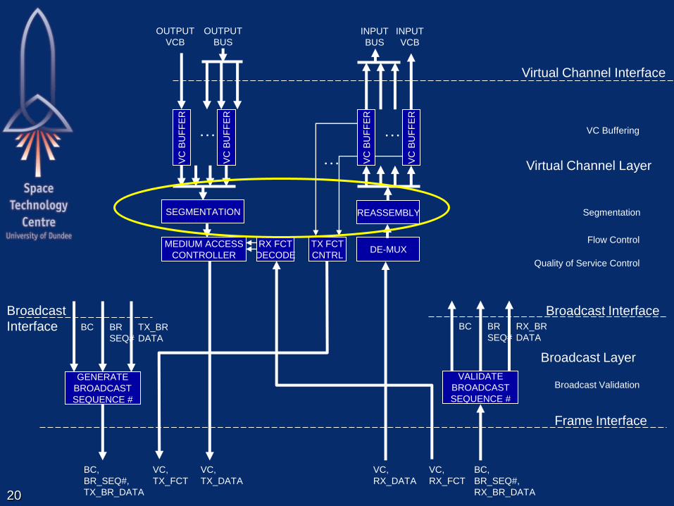
SpaceFibre Virtual Channels
Segmentation
– Splits SpaceWire packet stream into data frames
– Each frame contains a chunk of data
Up to 256 N-Chars
– Room for frame indicated by FCT
– Framing permits
Additional FDIR information
– CRC
– Sequence number
Isolates any errors, containing them in frame
Supports retry for robust communication
– Allows QoS to be implemented efficiently
21

SpaceFibre Data Frame
32-bit oriented, control words and data words
Start Data Frame
– Virtual Channel Number
Data field contains up to 256 N-Chars
– From one or more SpaceWire packets
End Data Frame
– Frame sequence Number, CRC 22
0 7 8 15 16 23 24 31
COMMA SDF VC Reserved
DATA 1 LS DATA 1 DATA 1 DATA 1 MS
DATA 2 LS DATA 2 DATA 2 DATA 2 MS
... ... ... ...
DATA N LS DATA N DATA N DATA N MS
EDF FR_SEQ# CRC_LS CRC_MS

23
VC,
TX_DATA
VC,
RX_DATA
Frame Interface
OUTPUT
BUS
VC,
RX_FCT
BC,
BR_SEQ#,
RX_BR_DATA
MEDIUM ACCESS
CONTROLLER
VC
BU
FF
ER
VC
BU
FF
ER
…
DE-MUX
VC
BU
FF
ER
VC
BU
FF
ER
…
TX FCT
CNTRL
RX FCT
DECODE
…
INPUT
BUS
OUTPUT
VCB
INPUT
VCB
VC Buffering
Flow Control
Quality of Service Control
Virtual Channel Layer
Broadcast Interface
VALIDATE
BROADCAST
SEQUENCE #
GENERATE
BROADCAST
SEQUENCE #
VC,
TX_FCT
BC,
BR_SEQ#,
TX_BR_DATA
BC RX_BR
DATA
BR
SEQ# BC TX_BR
DATA
BR
SEQ#
Broadcast Validation
Virtual Channel Interface
Broadcast
Interface
Broadcast Layer
SEGMENTATION REASSEMBLY Segmentation

SpaceFibre Virtual Channels
Flow Control
– Makes sure there is room in input VCB at far end
of the link
– Before sending a data frame
– Avoids blocking
– FCT exchanged for 256 N-Chars (full frame)
– FCT sent when input buffer has room for another
full data frame
24
25
VC,
TX_DATA
VC,
RX_DATA
Frame Interface
OUTPUT
BUS
VC,
RX_FCT
BC,
BR_SEQ#,
RX_BR_DATA
MEDIUM ACCESS
CONTROLLER
VC
BU
FF
ER
VC
BU
FF
ER
…
DE-MUX
VC
BU
FF
ER
VC
BU
FF
ER
…
TX FCT
CNTRL
RX FCT
DECODE
…
INPUT
BUS
OUTPUT
VCB
INPUT
VCB
VC Buffering
Flow Control
Quality of Service Control
Virtual Channel Layer
Broadcast Interface
VALIDATE
BROADCAST
SEQUENCE #
GENERATE
BROADCAST
SEQUENCE #
VC,
TX_FCT
BC,
BR_SEQ#,
TX_BR_DATA
BC RX_BR
DATA
BR
SEQ# BC TX_BR
DATA
BR
SEQ#
Broadcast Validation
Virtual Channel Interface
Broadcast
Interface
Broadcast Layer
SEGMENTATION REASSEMBLY Segmentation

SpaceFibre Virtual Channels
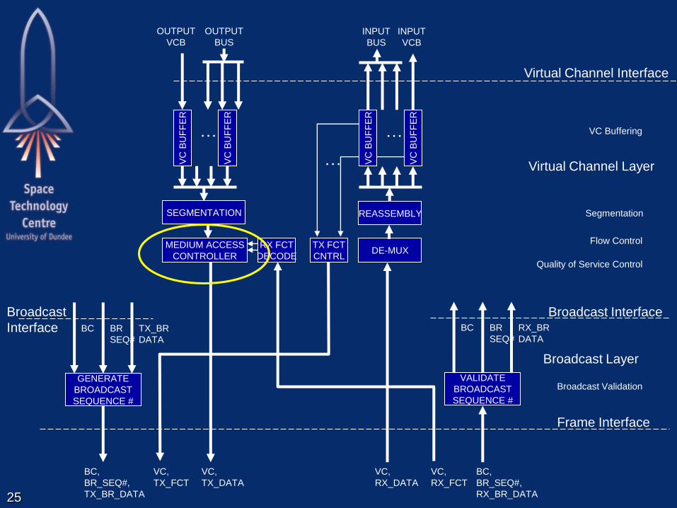
Medium Access Controller
– Determines what output VCB to send next frame
from
– Depends on:
Which output VCBs have data to send
Which input VCBs at other end of link have room
Arbitration or QoS policy in force for each virtual channel
26
SpaceFibre Virtual Channels
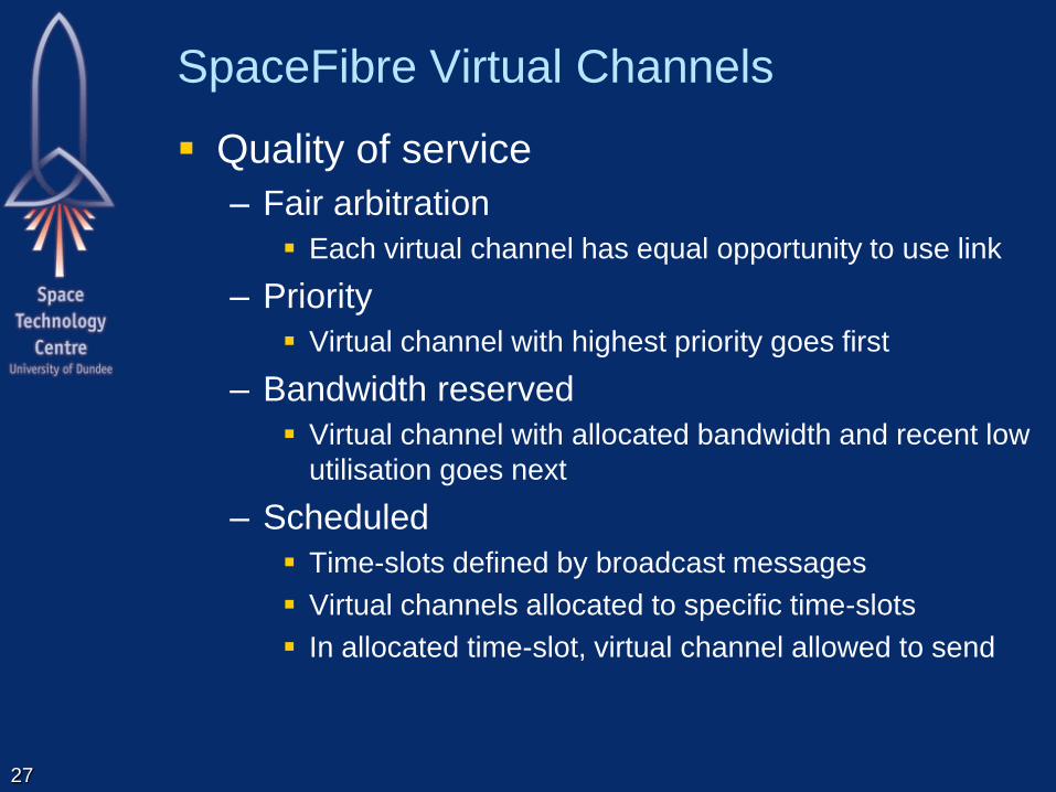
Quality of service
– Fair arbitration
Each virtual channel has equal opportunity to use link
– Priority
Virtual channel with highest priority goes first
– Bandwidth reserved
Virtual channel with allocated bandwidth and recent low
utilisation goes next
– Scheduled
Time-slots defined by broadcast messages
Virtual channels allocated to specific time-slots
In allocated time-slot, virtual channel allowed to send
27

Simulation Results
Bandwidth allocation
– One virtual channel
– Multiple virtual channels
All link bandwidth allocated
Some link bandwidth not allocated
Some non allocated bandwidth is used by one channel
with excess of throughput
– Source data burst
Priority
– Impact on bandwidth allocated
Scheduling
– Impact on latency and jitter
28

Simulation Results – One virtual channel that uses half bandwidth

•
Simulation Results
– Three virtual channels
– Throughput equal to allocated bandwidth
– 10% of available bandwidth not allocated and is not used by any channel
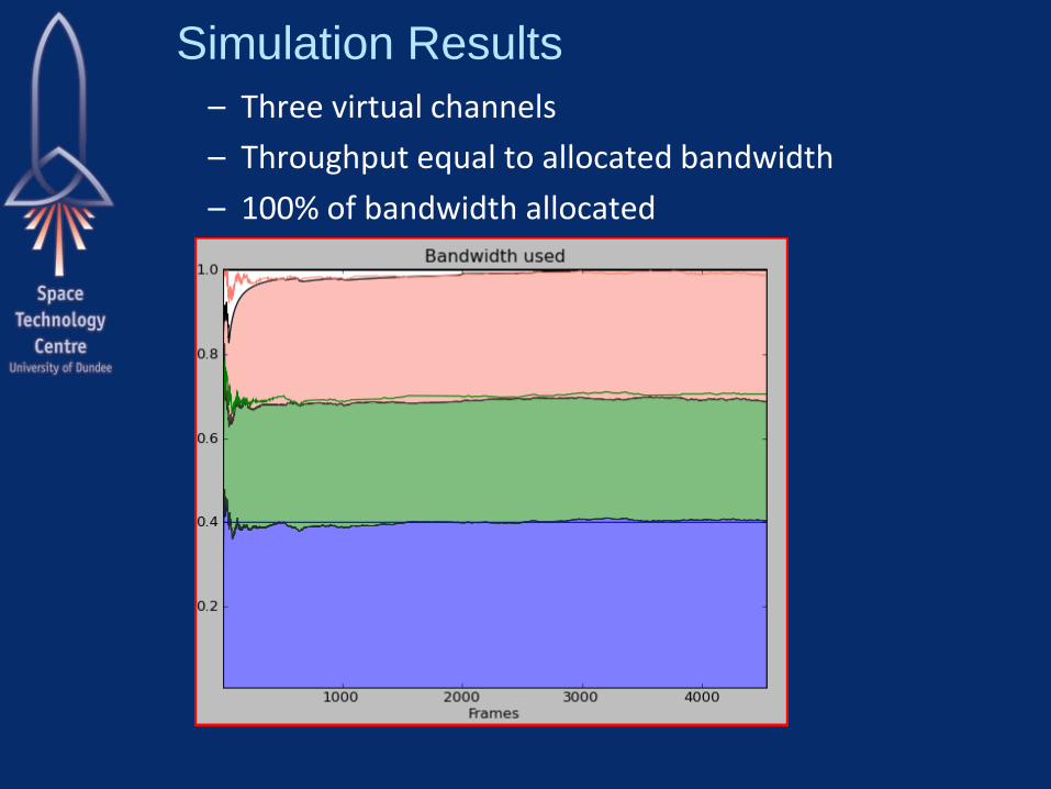
Simulation Results
– Three virtual channels
– Throughput equal to allocated bandwidth
– 100% of bandwidth allocated

•
Simulation Results
– Three virtual channels
– Throughput equal to allocated bandwidth Except for green channel
Green channel has more data to send than allocated
Uses the non-allocated bandwidth

Single bursty source channel
– Use in average 60% of the link
Bursty source channel and a constant source channel – Blue source packets are buffered to guarantee the bandwidth for the green
channel
Source data burst
33 Buffer empty

Priority
34
Priority reduces the latency and jitter of a channel
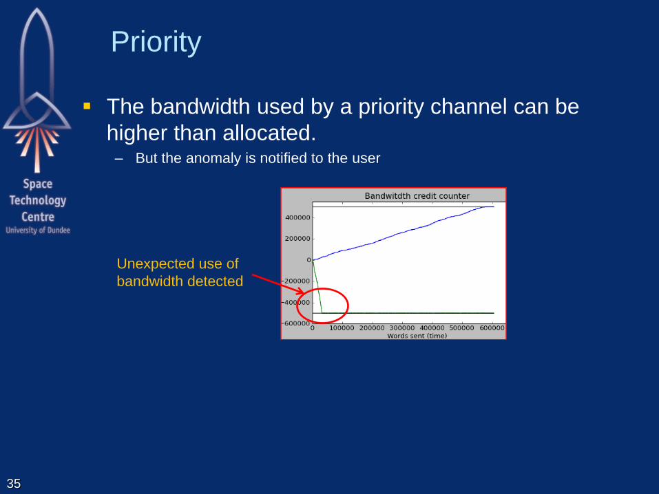
Priority
35
The bandwidth used by a priority channel can be
higher than allocated. – But the anomaly is notified to the user
Unexpected use of
bandwidth detected

Scheduling
36
If the data source is synchronized with the channel
schedule the latency and jitter is minimum.

SpaceFibre Broadcast Layer
37
Retry Interface
Retry Layer
Encoding/Decoding Interface
Encoding Layer
SerDes Interface
Serialisation Layer
Virtual Channel Layer
VC Interface
Serial Interface
Physical Layer
Lane Control Interface
Lane Control Layer
Lane Interface
Lane Layer
Broadcast Interface
Broadcast Layer
Framing Layer
Frame Interface
38
VC,
TX_DATA
VC,
RX_DATA
Frame Interface
OUTPUT
BUS
VC,
RX_FCT
BC,
BR_SEQ#,
RX_BR_DATA
MEDIUM ACCESS
CONTROLLER
VC
BU
FF
ER
VC
BU
FF
ER
…
DE-MUX
VC
BU
FF
ER
VC
BU
FF
ER
…
TX FCT
CNTRL
RX FCT
DECODE
…
INPUT
BUS
OUTPUT
VCB
INPUT
VCB
VC Buffering
Flow Control
Quality of Service Control
Virtual Channel Layer
Broadcast Interface
VALIDATE
BROADCAST
SEQUENCE #
GENERATE
BROADCAST
SEQUENCE #
VC,
TX_FCT
BC,
BR_SEQ#,
TX_BR_DATA
BC RX_BR
DATA
BR
SEQ# BC TX_BR
DATA
BR
SEQ#
Broadcast Validation
Virtual Channel Interface
Broadcast
Interface
Broadcast Layer
SEGMENTATION REASSEMBLY Segmentation

SpaceFibre Broadcast Channels
Broadcast Channel Interface
– Use to broadcast short messages across the
network and to receive those messages
– Can be used for many functions
Time distribution
Synchronisation
Network management
Event signalling
– Broadcast interface is a set of registers
Broadcast channel
Broadcast sequence number
Message type
Message data
39

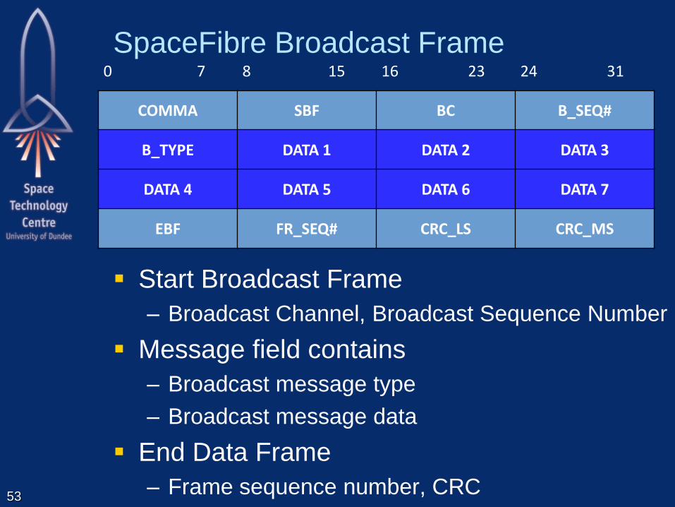
SpaceFibre Broadcast Frame
Start Broadcast Frame
– Broadcast Channel, Broadcast Sequence Number
Message field contains
– Broadcast message type
– Broadcast message data
End Data Frame
– Frame sequence number, CRC
40
0 7 8 15 16 23 24 31
COMMA SBF BC B_SEQ#
B_TYPE DATA 1 DATA 2 DATA 3
DATA 4 DATA 5 DATA 6 DATA 7
EBF FR_SEQ# CRC_LS CRC_MS
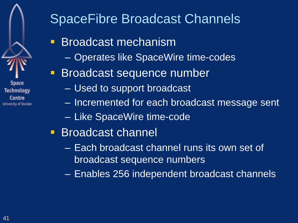
SpaceFibre Broadcast Channels
Broadcast mechanism
– Operates like SpaceWire time-codes
Broadcast sequence number
– Used to support broadcast
– Incremented for each broadcast message sent
– Like SpaceWire time-code
Broadcast channel
– Each broadcast channel runs its own set of
broadcast sequence numbers
– Enables 256 independent broadcast channels
41

SpaceFibre Broadcast Channels
Broadcast channels split into three types:
– Network management broadcast channels (0-31)
0-7: Time synchronisation
– 0-3 Time distribution
– 4-7 Synchronisation
8-31: Network control,
– Configuration, control, and FDIR of a SpaceFibre
network
– Node broadcast channels (32-253)
Each broadcast channel associated with the node
With logical address of the same value as the broadcast
channel number
– Reserved broadcast channels (254, 255)
42

SpaceFibre Broadcast Channels
Broadcast type
– Defines sematics of broadcast message
– E.g. “Time” type
Data field contains seven bytes of system time
Subscription
– User application can subscribe to particular
Broadcast channels
Broadcast message types
– Only receive notification of messages they
subscribe to
43
SpaceFibre Framing Layer
44
Retry Interface
Retry Layer
Encoding/Decoding Interface
Encoding Layer
SerDes Interface
Serialisation Layer
Virtual Channel Layer
VC Interface
Serial Interface
Physical Layer
Lane Control Interface
Lane Control Layer
Lane Interface
Lane Layer
Broadcast Interface
Broadcast Layer
Framing Layer
Frame Interface

SpaceFibre Data Frame
32-bit oriented, control words and data words
Start Data Frame
– Virtual Channel Number
Data field contains N-Chars
– From one or more SpaceWire packets
End Data Frame
– Frame sequence Number, CRC 45
0 7 8 15 16 23 24 31
COMMA SDF VC Reserved
DATA 1 LS DATA 1 DATA 1 DATA 1 MS
DATA 2 LS DATA 2 DATA 2 DATA 2 MS
... ... ... ...
DATA N LS DATA N DATA N DATA N MS
EDF FR_SEQ# CRC_LS CRC_MS
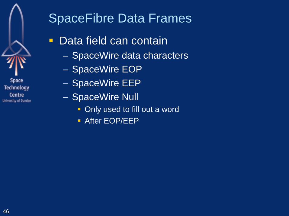
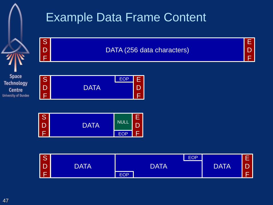
SpaceFibre Data Frames
Data field can contain
– SpaceWire data characters
– SpaceWire EOP
– SpaceWire EEP
– SpaceWire Null
Only used to fill out a word
After EOP/EEP
46
DATA
EOP
Example Data Frame Content
47
DATA (256 data characters)
S
D
F
E
D
F
DATA
S
D
F
EOP E
D
F
DATA
S
D
F EOP
E
D
F
NULL
DATA
S
D
F EOP
E
D
F
DATA

EOP, EEP, Null Coding
Must be able to differentiate
– EOP, EEP, Null
– From Data characters
Use K-codes
– EOP K28.0
– EEP K28.2
– Null K28.6
None of these contain comma
– Since they can occur anywhere in a word
– Comma must only occur in LS symbol position
Data values of these K-codes
– Used in scrambling, CRC
– K-code value not replace when scrambling
48

Data Scrambling
Spread the spectrum of data / idle frames
By convolution
– with a broad spectrum signal
– i.e. a noise or random number source
Convolution in frequency domain is
multiplication in time domain.
Multiplication of a bit sequence can be done
by XOR
49

Data Scrambling
Bit wise multiplication (XOR) of data with a
sequence of random numbers produced from
a scrambling polynomial
The scrambling polynomial is
G(x) = X16 + X5 + X4+ X3+ 1
Seed for scrambler is 0xffff
Re-seeded at the start of every new data or
idle frame
Data field of data frames and idle frames
scrambled prior to transmission
50

De-Scrambling
De-convolve known “noise” from received
signal
De-convolution in frequency domain is
division in time domain
Multiplication and division give the same
result in bit-wise boolean algebra 0 represents -1, 1 represents +1
-1 x -1 = +1 -1 / -1 = +1 0 XOR 0 = 1
-1 x +1 = -1 -1 / +1 = -1 0 XOR 1 = 0
+1 x -1 = -1 +1 / -1 = -1 0 XOR 1 = 0
+1 x +1 = +1 +1 / +1 = +1 1 XOR 1 = 1
Therefore XOR the incoming bit stream with
the scrambling polynomial to recover data
51

Scrambler/De-Scrambler
52
Random Number Generator
D Q D Q D Q D Q D Q
D Q D Q D Q D Q D Q D Q D Q D Q
D Q
D Q D Q
XOR XOR XOR
D9 D11 D10 D12 D13 D14 D15 D6 D8 D7
D3 D4 D5 D0 D2 D1
Bit Stream Input
D Q D Q D Q D Q D Q D Q D Q D Q
XOR
Data In
CLK
D7 D6 D4 D5 D3 D2 D1 D0
Data
Out
CLK
SpaceFibre Broadcast Frame
Start Broadcast Frame
– Broadcast Channel, Broadcast Sequence Number
Message field contains
– Broadcast message type
– Broadcast message data
End Data Frame
– Frame sequence number, CRC
53
0 7 8 15 16 23 24 31
COMMA SBF BC B_SEQ#
B_TYPE DATA 1 DATA 2 DATA 3
DATA 4 DATA 5 DATA 6 DATA 7
EBF FR_SEQ# CRC_LS CRC_MS

0 7 8 15 16 23 24 31
COMMA SIF FR_SEQ# RESERVED
SEED LS SEED SEED SEED MS
PRBS 1 LS PRBS 1 PRBS 1 PRBS 1 MS
PRBS 2 LS PRBS 2 PRBS 2 PRBS 2 MS
... ... ... ...
PRBS N LS PRBS N PRBS N PRBS N MS
SpaceFibre Idle Frame
Start Idle Frame
– Frame Sequence Number
Data field contains
– Seed for pseudo-random sequence
– Pseudo-random bit sequence
No End of Frame
– Ended by the start of next data or broadcast frame
54

0 7 8 15 16 23 24 31
FCT VC FR_SEQ# CRC8
SpaceFibre FCT Control Word
FCT
– FCT identifier symbol (K23.7)
Virtual Channel
– Virtual channel number
– FCT is for this virtual channel
FR_SEQ#
– Frame sequence number
– So missing/erroneous FCTs can be recovered
CRC8
– For integrity checking of FCT
55

Framing Layer
56
TX_DATA_FR RX_DATA_FR
32+4 32+4
DATA
SCRAMBLER
VC,
TX_DATA
DATA
DE- SCRAMBLER
VC,
RX_DATA
32+4 32+4
STRIP FRAME
DELIMITERS
ADD FRAME
DELIMITERS
VC,
RX_FCT
BC,
B_SEQ#,
RX_B_DATA
ADD FRAME
DELIMITERS
VC,
TX_FCT
BC,
B_SEQ#,
TX_B_DATA
TX_BC FR
32+4
RX_BC_FR
32+4
RX_FCT
32+4
STRIP FRAME
DELIMITERS FRAME FCT EXTRACT
FCT
32+4
TX_FCT
32+4 32+4 32+4 32+4

Transmit Framing
57
32+4
ADD FRAME
DELIMITERS
BC,
B_SEQ#,
TX_B_DATA
TX_BC FR
32+4
VC,
TX_FCT
FRAME FCT
32+4
TX_FCT
32+4
TX_DATA_FR
32+4
DATA
SCRAMBLER
VC,
TX_DATA
ADD FRAME
DELIMITERS
32+4
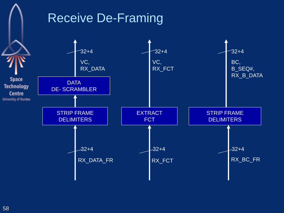
Receive De-Framing
58
32+4
BC,
B_SEQ#,
RX_B_DATA
RX_BC_FR
32+4
STRIP FRAME
DELIMITERS
VC,
RX_FCT
RX_FCT
32+4
EXTRACT
FCT
32+4
RX_DATA_FR
32+4
DATA
DE- SCRAMBLER
VC,
RX_DATA
STRIP FRAME
DELIMITERS
32+4

SpaceFibre Retry Layer
59
Retry Interface
Retry Layer
Encoding/Decoding Interface
Encoding Layer
SerDes Interface
Serialisation Layer
Virtual Channel Layer
VC Interface
Serial Interface
Physical Layer
Lane Control Interface
Lane Control Layer
Lane Interface
Lane Layer
Broadcast Interface
Broadcast Layer
Framing Layer
Frame Interface

SpaceFibre Retry Layer - Transmit
60
MUX
TX_DATA_FR
32+4
IDLE
FRAME
FRAME
RETRY
BUFFER
TX_BC FR
32+4
MUX
32+4
TX_FCT
ACK/
NACK
CNTRL
ACK/NACK
ACK/
NACK
SEQ#
CHK OK
ADD SEQ#
CRC
CHK OK
MUX
MUX
MUX
ADD SEQ#
ADD CRC
ADD SEQ# ADD SEQ#
ADD CRC
SEQ#
GEN
ADD CRC

SpaceFibre Retry Layer - Transmit
61
TX_DATA_FR
32+4
TX_BC FR
32+4 32+4
TX_FCT
MUX
MUX
ADD SEQ#
ADD CRC
ADD SEQ# ADD SEQ#
ADD CRC
SEQ#
GEN
ADD CRC

Multiplexing of Frames and FCTs
62
Data Frames
Broadcast Frames
FCTs
Idle frames
4 7
1 3 6
2 5
7
8
Data stream 7 1 3 6 2 5 7 8 4

SpaceFibre Retry Layer - Transmit
63
MUX
IDLE
FRAME
FRAME
RETRY
BUFFER
MUX
ACK/
NACK
CNTRL
ACK/NACK
ACK/
NACK
SEQ#
CHK OK
ADD SEQ#
CRC
CHK OK
MUX
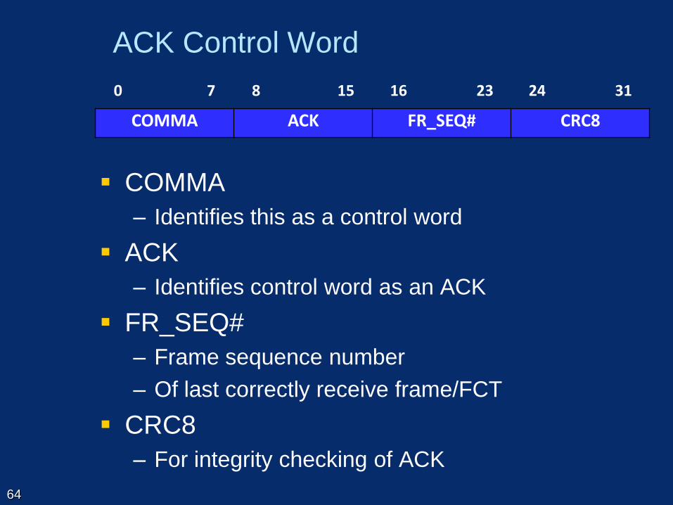
0 7 8 15 16 23 24 31
COMMA ACK FR_SEQ# CRC8
ACK Control Word
COMMA
– Identifies this as a control word
ACK
– Identifies control word as an ACK
FR_SEQ#
– Frame sequence number
– Of last correctly receive frame/FCT
CRC8
– For integrity checking of ACK
64
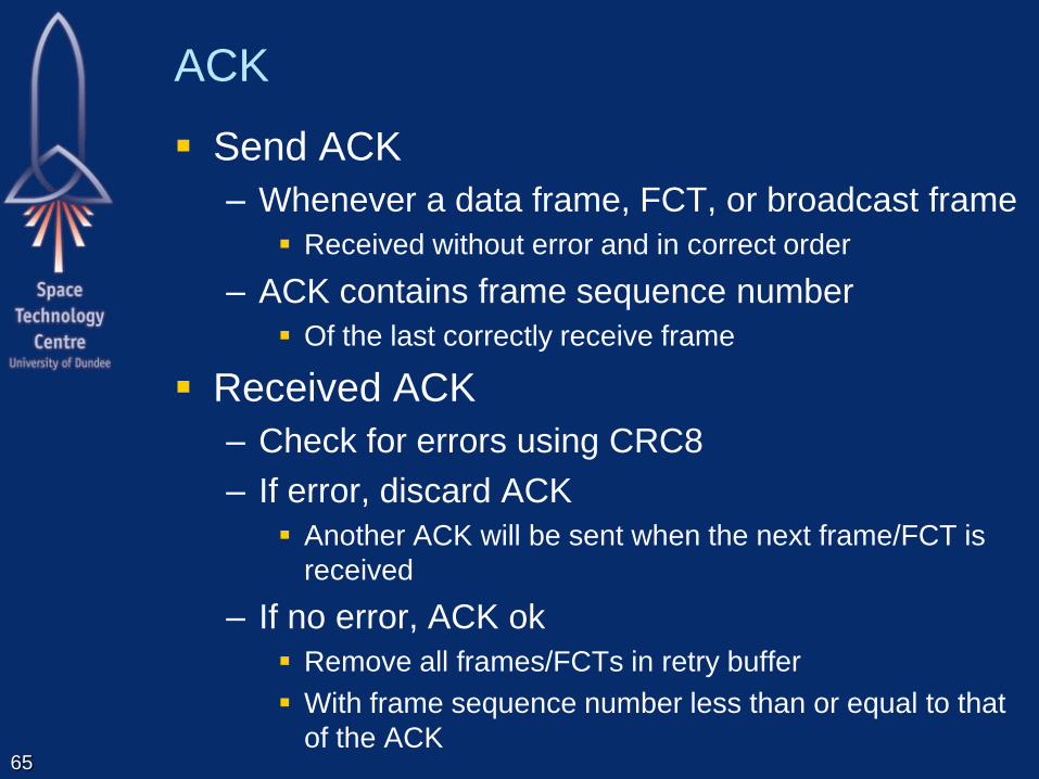
ACK
Send ACK
– Whenever a data frame, FCT, or broadcast frame
Received without error and in correct order
– ACK contains frame sequence number
Of the last correctly receive frame
Received ACK
– Check for errors using CRC8
– If error, discard ACK
Another ACK will be sent when the next frame/FCT is
received
– If no error, ACK ok
Remove all frames/FCTs in retry buffer
With frame sequence number less than or equal to that
of the ACK
65
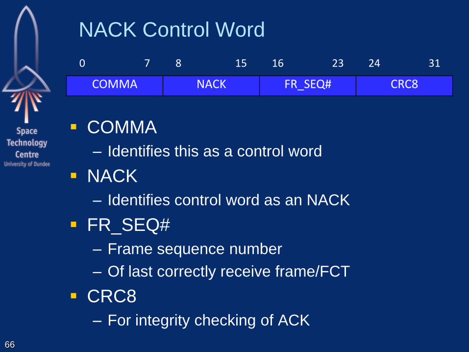
0 7 8 15 16 23 24 31
COMMA NACK FR_SEQ# CRC8
NACK Control Word
COMMA
– Identifies this as a control word
NACK
– Identifies control word as an NACK
FR_SEQ#
– Frame sequence number
– Of last correctly receive frame/FCT
CRC8
– For integrity checking of ACK
66

NACK
Send NACK
– Whenever a data frame, FCT, or broadcast frame
Received with error or in wrong order
– NACK contains frame sequence number
Of the last correctly receive frame
Received NACK
– Check for errors using CRC8
– If error, discard NACK
Another NACK will be sent when the next frame/FCT is
received
– If no error, NACK ok
Resend all frames/FCTs in retry buffer
With frame sequence number greater than that of the
NACK
67
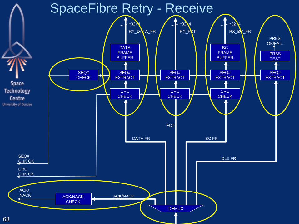
SpaceFibre Retry - Receive
68
RX_DATA_FR
32+4
CRC
CHECK
ACK/NACK
CHECK
ACK/NACK
SEQ#
EXTRACT
PRBS
OK/FAIL DATA
FRAME
BUFFER
DEMUX
BC FR
IDLE FR
FCT
DATA FR
RX_BC_FR
32+4
RX_FCT
32+4
SEQ#
CHK OK
SEQ#
EXTRACT
CRC
CHECK
SEQ#
EXTRACT
BC
FRAME
BUFFER
SEQ#
EXTRACT
PRBS
TEST
SEQ#
CHECK
CRC
CHK OK
ACK/
NACK
CRC
CHECK
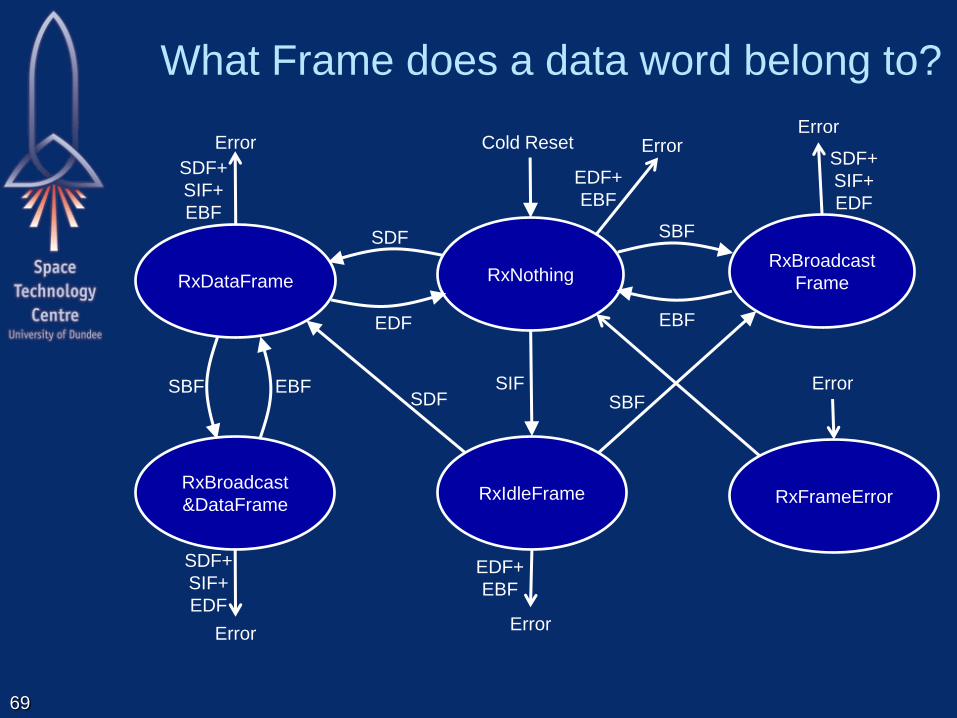
What Frame does a data word belong to?
69
RxIdleFrame
SIF
RxDataFrame
RxBroadcast
&DataFrame
RxNothing RxBroadcast
Frame
SBF SBF
SDF
SDF
EDF
EBF
EBF
SBF
Cold Reset
SDF+
SIF+
EBF
Error
EDF+
EBF
Error SDF+
SIF+
EDF
Error
SDF+
SIF+
EDF
Error
EDF+
EBF
Error
RxFrameError
Error
Link Layer Retry
Small amount of memory required
– To support many sources and virtual channels
Rapid recovery from
– Transient and persistent errors
Signals permanent error
– To network manager
– Using broadcast frame
Isolates effects of faults to where they occur
– Minimises the effect on the system
70

SpaceFibre Lane Control Layer
71
Retry Interface
Retry Layer
Encoding/Decoding Interface
Encoding Layer
SerDes Interface
Serialisation Layer
Virtual Channel Layer
VC Interface
Serial Interface
Physical Layer
Lane Control Interface
Lane Control Layer
Lane Interface
Lane Layer
Broadcast Interface
Broadcast Layer
Framing Layer
Frame Interface

Lane Control Layer
72
32+4 32+4
MUX
MUX
LANE#
LANE DISTRIBUTOR
MUX
LANE#
…
MUX
LANE#
LANE
CONTROL
MUX
SYNC
FIFO
LANE CONCENTRATOR
…
LANE
DETECT
LANE
DETECT
LANE
DETECT
LANE ACTIVE
MUX
To other
Lanes
From other
Lanes
Required Lanes
SYNC
FIFO
SYNC
FIFO
From other
Lanes
Data & Control
Words
Data & Control
Words
Data & Control
Words
Data & Control
Words
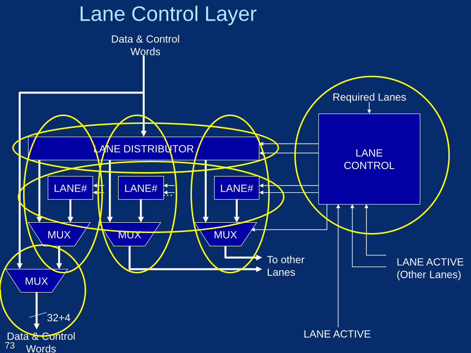
Lane Control Layer
73
32+4
MUX
MUX
LANE#
LANE DISTRIBUTOR
MUX
LANE# …
MUX
LANE#
LANE
CONTROL
LANE ACTIVE
To other
Lanes
Required Lanes
Data & Control
Words
Data & Control
Words
LANE ACTIVE
(Other Lanes)

0 7 8 15 16 23 24 31
COMMA LSYNC LANE # RESERVED
Lane Sync Control Word
COMMA
– Identifies this as a control word
LSYNC
– Identifies control word as a Lane Sync control word
LANE#
– Lane number
– 1 to 10 lanes
– 0, implies lane not being used
Reserved
74

Lane Control Layer
75
32+4
LANE
CONTROL
MUX
SYNC
FIFO
LANE CONCENTRATOR
…
LANE
DETECT
LANE
DETECT
LANE
DETECT
LANE ACTIVE
MUX
From other
Lanes
Required Lanes
SYNC
FIFO
SYNC
FIFO
From other
Lanes
Data & Control
Words
Data & Control
Words

SpaceFibre Encoding Layer
76
Retry Interface
Retry Layer
Encoding/Decoding Interface
Encoding Layer
SerDes Interface
Serialisation Layer
Virtual Channel Layer
VC Interface
Serial Interface
Physical Layer
Lane Control Interface
Lane Control Layer
Lane Interface
Lane Layer
Broadcast Interface
Broadcast Layer
Framing Layer
Frame Interface

Lane Layer
77
INIT_1
INIT_2
STANDBY
LOS
MUX
LANE
INITIALISATION
AND STANDBY
CONTROLLER
SYNC
IDLE
MUX
SKIP
32+4 32+4
32+4
32+4
32+4 32+4
MUX
IDLE MUX
LoS Inv Rx
LANE ACTIVE
LANE LAYER
ORDERED SET
EXTRACTION
RECEIVE
ELASTIC
BUFFER
SKIP
INSERTION
COUNTER
Data/Control Words Data/Control Words
Data/Control Words Data/Control Words

Lane Control-Words
SKIP
– Supports receive elastic buffer
– Set every 5000 words
IDLE
– Sent when nothing else to send
INIT1
– Used for initialisation handshake
INIT2
– Used for initialisation handshake
STANDBY
– Sent to indicate about to go into Standby mode
LOS
– Sent to indicate receiver lost signal 78

Precedence of frames and control words
SKIP, highest precedence
LoS
Standby
LSYNC
ACK/NACK
Broadcast frame
FCT
Data frame
Idle frame
IDLE, lowest precedence.
79

Lane Initialisation State Machine
80
WarmReset
Disable TX, RX
ColdReset
Disable TX, RX
FailedInit
NotConnected
Send INIT1
AutoStart
Disable TX
Warm_Reset Cold_Reset
Auto_Start
#Auto_Start
Lane_Start +
2x Got_INIT1
ChangingPolarity
Invert Rx Polarity 4x INIT1_WrongPolarity
NearEndConnected
Send 16x INIT2
FarEndConnected
Send 16x INIT2
Lane_Start.
#Lane_Start.#Auto
Timeout(10μs)
8xGot_INIT2 8xGot_INIT1
Lost_Sync
#Start.#Auto
WarmReset
Connected
Send 8x IDLE
Connected
WarmReset
FailedInit
#Start.#Auto
Lost_Sync +
Timeout(10us)
WarmReset #Start.#Auto
FailedInit
Lost_Sync
Active
Connected
8xGot_INIT2
. Sent 16x INIT2s
WarmReset
Standby + LOS
NotConnected
Lost_Sync + Got_INIT1
ChangingCapability
Update parameters
WarmReset
4xINIT1_Wrong_Polarity
PrepareStandby
Send 16x Standby LossOfSignal
Send 16x LoS
#Start.#Auto Receiver Lost Signal
WarmReset
WarmReset
Capability Parameters
Do Not Match
Capability
Parameters
Match
Sent 16x INIT2s

Lane Initialisation State Machine
81
WarmReset
Disable TX, RX
FailedInit
NotConnected
Send INIT1
AutoStart
Disable TX
Warm_Reset
ColdReset
Disable TX, RX
Cold_Reset
Auto_Start
Lane_Start +
2x Got_INIT1
ChangingPolarity
Invert Rx Polarity
Lane_Start.
#Lane_Start.#Auto
Timeout(10μs)
8xGot_INIT2 8xGot_INIT1
. Sent 8x INIT1s
Lost_Sync
#Start.#Auto
WarmReset
Connected
Send 8x IDLE
Connected
WarmReset
#Start.#Auto
FailedInit
Lost_Sync +
Timeout(10us)
WarmReset #Start.#Auto
FailedInit
Lost_Sync
8xGot_INIT2
. Sent 16x INIT2s
4xINIT1_Wrong_Polarity
#Auto_Start
4x INIT1_WrongPolarity
Sent 16x INIT2s
NearEndConnected
Send 16x INIT2
FarEndConnected
Send 16x INIT2

Lane Initialisation State Machine
82
Connected
Send 8x IDLE
Connected
NotConnected
Lost_Sync + Got_INIT1
WarmReset
PrepareStandby
Send 16x Standby
#Start.#Auto
LossOfSignal
Send 16x LoS
Receiver Lost Signal
WarmReset WarmReset
Standby + LOS WarmReset
ChangingCapability
Update parameters
Capability Parameters
Do Not Match
Active
Connected
Capability
Parameters
Match
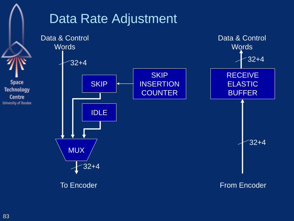
Data Rate Adjustment
83
IDLE
SKIP
SKIP
INSERTION
COUNTER
32+4
MUX
32+4
To Encoder
Data & Control
Words
RECEIVE
ELASTIC
BUFFER
32+4
32+4
From Encoder
Data & Control
Words

Receive Elastic Buffer
Receive clock and system clock will be at
slightly different frequencies
Receive elastic buffer makes up for these
differences
Read
Local CLK Write
Receive CLK
Nominal condition buffer half-full
Read
Local CLK

Receive Elastic Buffer
When buffer less than half full
Local CLK is faster than Receive CLK
Skip characters are read but read pointer not
incremented (once only)
Effect is to add Skips to the buffer Read
Local CLK
Write
Receive CLK
Skip
Buffer less than half full (emptying)

Receive Elastic Buffer
When buffer more than half full
Local CLK is slower than Receive CLK
Skip characters are skipped: read pointer
incremented past them
Effect is to remove skips from buffer Read
Local CLK Write
Receive CLK
Skip
Buffer more than half full (filling up)
Read
Local CLK
Read
Local CLK

Receive Elastic Buffer
Must ensure that there are sufficient Skips in
the data stream
So that they can be removed if necessary
Frequency of Skips depends on:
– Size of elastic buffer
– Maximum frequency difference between
Local CLK: System clock at this end of link
Receive CLK: System clock at other end of link
One skip every 5000 data or control words

SpaceFibre Encoding Layer
88
Retry Interface
Retry Layer
Encoding/Decoding Interface
Encoding Layer
SerDes Interface
Serialisation Layer
Virtual Channel Layer
VC Interface
Serial Interface
Physical Layer
Lane Control Interface
Lane Control Layer
Lane Interface
Lane Layer
Broadcast Interface
Broadcast Layer
Framing Layer
Frame Interface

SpaceFibre Encoding Layer
89
8B/10B
ENCODER
8B/10B
DECODER
SYMBOL
SYNC
8B/10B
ENCODER
8B/10B
DECODER
MUX
10, 20, 40
8+1, 16+2 , 32+4
32+4 32+4
10, 20, 40
8+1, 16+2, 32+4
WORD SYNC
ERROR
DECODER
Inv Rx LoS SYNC
RECEIVE
SYNC
STATE MCH.
Inv Rx LoS
Data & Control
Words Data & Control
Words
Data & K-Code
Symbols
Data & K-Code
Symbols

90
8B/10B Coding
Zero DC bias:
– same number of ones and zeros
10-bit symbols representing
– 8-bit data codes
– Some control codes, K-codes
– Codes use
5 ones and 5 zeros
4 ones and 6 zeros
6 ones and 4 zeros
– Characters with different number of 1s and 0s
have two possible codes to preserve DC bias
91
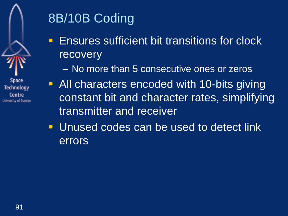
8B/10B Coding
Ensures sufficient bit transitions for clock
recovery
– No more than 5 consecutive ones or zeros
All characters encoded with 10-bits giving
constant bit and character rates, simplifying
transmitter and receiver
Unused codes can be used to detect link
errors

92
8B/10B Encoder
5B/6B
Encoder
3B/4B
Encoder
Running
Disparity
5 ls-bits 6-bits
3 ms-bits 4-bits
8-bit Data
Input
Control/Data
Input (K/D)
10-bit
Encoded
Output 5B/6B Disparity
3B/4B Disparity
93
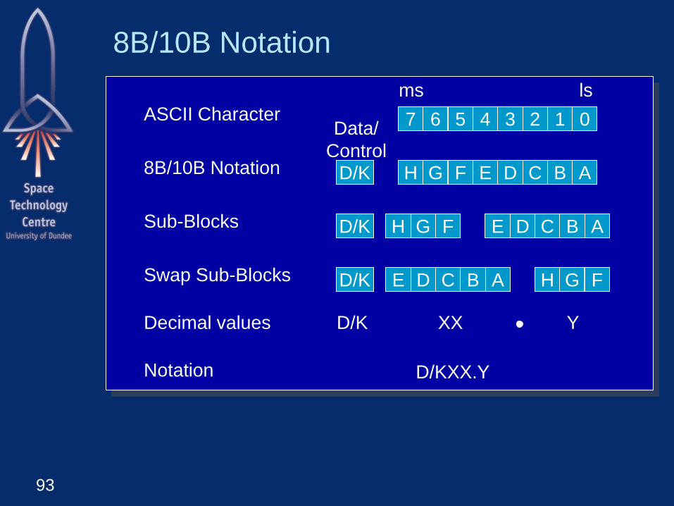
8B/10B Notation
7 6 5 4 3 2 1 0
H G F E D C B A
H G F E D C B A
H G F E D C B A
ms ls
D/K
D/K
D/K
Data/
Control
ASCII Character
8B/10B Notation
Sub-Blocks
Swap Sub-Blocks
Decimal values D/K XX Y
Notation D/KXX.Y
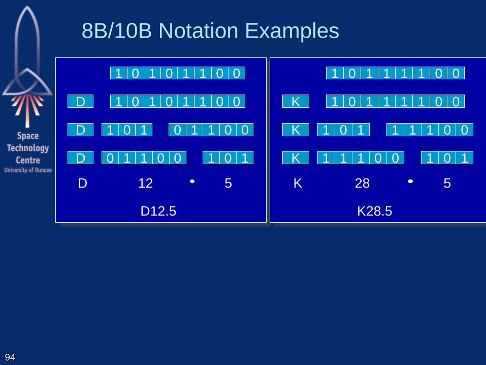
8B/10B Notation Examples
94
1 0 1 0 1 1 0 0
1 0 1 0 1 1 0 0
1 0 1 0 1 1 0 0
1 0 1 0 1 1 0 0
D
D
D
D 12 5
D12.5
1 0 1 1 1 1 0 0
1 0 1 1 1 1 0 0
1 0 1 1 1 1 0 0
1 0 1 1 1 1 0 0
K
K
K
K 28 5
K28.5

95
Part of 5B/6B Encoding Table
Input Output
Data Input Data bits 43210
(EDCBA)
Current Running
Disparity -ve
abcdei
Current Running
Disparity +ve
abcdei
D00.y 00000 100111 011000
D01.y 00001 011101 100010
D02.y 00010 101101 010010
D03.y 00011 110001
D04.y 00100 110101 001010
D05.y 00101 101001
D06.y 00110 011001
D07.y 00111 111000 000111
D08.y 01000 111001 000110
D09.y 01001 100101
D10.y 01010 010101

96
3B/4B Encoding
Input Output
Data Input Data bits 765
(HGF)
3B/4B
Disparity -ve
fghj
3B/4B
Disparity +ve
fghj
D/Kxx.0 000 1011 0100
Dxx.1 001 1001
Kxx.1 001 0110 1001
Dxx.2 010 0101
Kxx.2 010 1010 0101
D/Kxx.3 011 1100 0011
D/Kxx.4 100 1101 0010
Dxx.5 101 1010
Kxx.5 101 0101 1010
Dxx.6 110 0110
Kxx.6 110 1001 0110
Dxx.7 111 1110/0111 0001/1000
Kxx.7 111 0111 1000

97
8B/10B Control (K) Codes
Input Output
Special Character
Name
Current Running
Disparity -ve
Current Running Disparity
+ve
K28.0 001111 0100 110000 1011
K28.1 001111 1001 110000 0110
K28.2 001111 0101 110000 1010
K28.3 001111 0011 110000 1100
K28.4 001111 0010 110000 1101
K28.5 001111 1010 110000 0101
K28.6 001111 0110 110000 1001
K28.7 001111 1000 110000 0111
K23.7 111010 1000 000101 0111
K27.7 110110 1000 001001 0111
K29.7 101110 1000 010001 0111
K30.7 011110 1000 100001 0111

SpaceFibre Synchronisation
Bit synchronisation
– Extracting bits from receiver output
Symbol synchronisation
– Extracting symbols from the bit stream
Word synchronisation
– Extracting words from the symbol stream
Lane synchronisation
– Combining words from several lanes into data
stream
Frame synchronisation
– Data frames
– Broadcast frames
– Idle frames
98

Bit Synchronisation
Receive Clock Recovery
99
Voltage
Controlled
Oscillator
Phase
Detector Input Signal
(data with
embedded clock)
Reference
Clock
Recovered
Bit Clock
Loop
Filter
Phase
Difference
Filtered
Control
Voltage

100
Symbol synchronisation
8B/10B Comma Pattern
– Three control codes contain a unique 7-bit pattern
– 0011111 or 1100000
– Does not occur in data codes
– Cannot be produced by combining any data code
or other control code
– Pattern is known as the comma pattern
– Widely used for character synchronisation

Symbol synchronisation
Commas – Used to detect the character boundaries in the
serial bit stream
– Contain unique seven bit sequences
Plus Comma – 0011111
Negative Comma – 1100000
Example
01001100111110010101011100
Comma
Start of Character
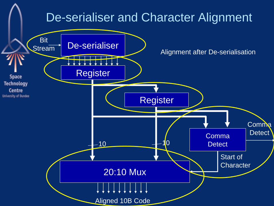
De-serialiser and Character Alignment
De-serialiser Bit
Stream
Register
Register
20:10 Mux
Comma
Detect 10 10
Aligned 10B Code
Start of
Character
Comma
Detect
Alignment after De-serialisation

De-serialiser and Character Alignment
De-serialiser Bit Stream
Register
Comma
Detect
Aligned 10B Code
Start of
Character
Comma
Detect
Bit Counter
Reset
Alignment during De-serialisation

Receive Synchronisation State Machine
104
Check
Sync Ready Four sequential
valid symbols
comma
received
Less than four
sequential
valid symbols
> 4 Four
RX errors
Word realignment
Not RX error AND
Not word realignment
RX error = disparity or invalid symbol error
Lost
Sync
No comma
received
Reset
Word realignment = word synchronisation lost (i.e. comma in position other than LS byte)
RX error
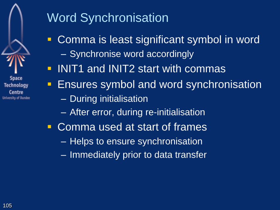
Word Synchronisation
Comma is least significant symbol in word
– Synchronise word accordingly
INIT1 and INIT2 start with commas
Ensures symbol and word synchronisation
– During initialisation
– After error, during re-initialisation
Comma used at start of frames
– Helps to ensure synchronisation
– Immediately prior to data transfer
105

SpaceFibre Serialisation Layer
106
Retry Interface
Retry Layer
Encoding/Decoding Interface
Encoding Layer
SerDes Interface
Serialisation Layer
Virtual Channel Layer
VC Interface
Serial Interface
Physical Layer
Lane Control Interface
Lane Control Layer
Lane Interface
Lane Layer
Broadcast Interface
Broadcast Layer
Framing Layer
Frame Interface

SpaceFibre Serialisation Layer
107
SERIALISER
DRIVER RECEIVER
DE-SERIALISER CLOCK
RECOVERY
MUX
MUX
10, 20, 40 10, 20, 40
INVERTER
Inv Rx LoS
Data & K-Code
Symbols
Data & K-Code
Symbols
Serial Data
Out
Serial Data
In
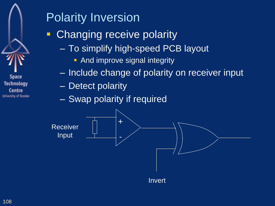
Polarity Inversion
Changing receive polarity
– To simplify high-speed PCB layout
And improve signal integrity
– Include change of polarity on receiver input
– Detect polarity
– Swap polarity if required
108
Invert
+
-
Receiver
Input

Loopback
Normal operation
Internal parallel loopback
Internal serial loopback
TX
CODING
TX
SERIALISER
RX
DECODING RX
DESERIALISER
MUX
MUX
TXDATA
RXDATA
Parallel
Loopback
TXP/TXN
RXP/RXN
Serial
Loopback

SpaceFibre Physical Layer
110
Retry Interface
Retry Layer
Encoding/Decoding Interface
Encoding Layer
SerDes Interface
Serialisation Layer
Virtual Channel Layer
VC Interface
Serial Interface
Physical Layer
Lane Control Interface
Lane Control Layer
Lane Interface
Lane Layer
Broadcast Interface
Broadcast Layer
Framing Layer
Frame Interface

Physical Layer
Required characteristics specified
– Drivers/Receivers
– Line
– Cable
– Connectors
Different physical layers
– Copper
CML
LVDS up to 1 Gbit/s operation
– Fibre
Optical fibre
100 m or more
111
Spaceflight Implementation
How can we implement this today
– For flight applications
– Avoiding several years of chip development and
qualification effort?
Difficult bit is the SerDes
– Runs at high speed
– Requires analogue phase-locked loop
Solution: use existing radiation tolerant
SerDes and FPGA
Possibly Xilinx if the MGTs are radiation
tolerant?
112

Flight Implementation
113
FPGA
SerDes
Serialisation
Encoding
Link Control
Lane Control
Retry
Framing
Virtual Channels
Broadcast Channel
Application
Logic

TLK2711-SP
TLK2711-SP
– Radiation tolerant SerDes
– Includes 8B/10B encoder/decoder
– Runs at 2.5 Gbits/s
2 Gbit/s actual data rate
– Combined with a radiation tolerant FPGA
– Can be used to implement radiation tolerant
SpaceFibre interface
Problem: incompatible with draft SpaceFibre
standard!
SpaceFibre specification modified to be able
to use this device
Also possible to use other SerDes devices 114
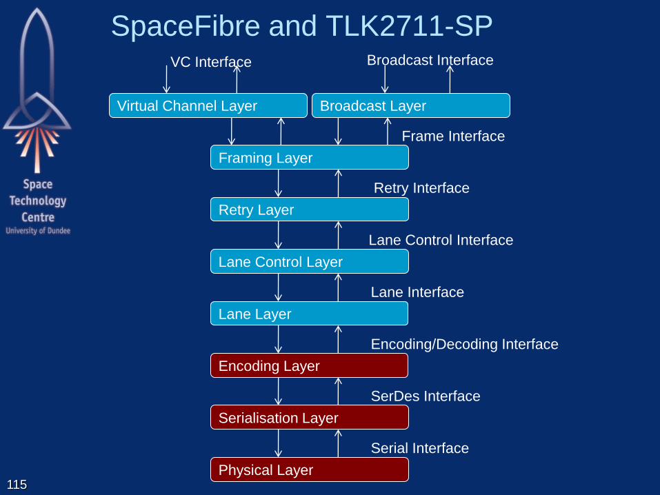
SpaceFibre and TLK2711-SP
115
Retry Interface
Retry Layer
Encoding/Decoding Interface
Encoding Layer
SerDes Interface
Serialisation Layer
Virtual Channel Layer
VC Interface
Serial Interface
Physical Layer
Lane Control Interface
Lane Control Layer
Lane Interface
Lane Layer
Broadcast Interface
Broadcast Layer
Framing Layer
Frame Interface

116
INIT_1
INIT_2
STANDBY
LOS
8B/10B
ENCODER
SERIALISER
DRIVER RECEIVER
DE-SERIALISER
8B/10B
DECODER
SYMBOL
SYNC
RECEIVE
ELASTIC
BUFFER
CLOCK
RECOVERY
MUX
MUX
LANE LAYER
ORDERED SET
EXTRACTION
LANE
INITIALISATION
AND STANDBY
CONTROLLER
RECEIVE
SYNC
STATE MCH.
SYNC
SerDes Interface
Lane Interface
MUX
IDLE
MUX
SKIP
SKIP
INSERTION
COUNTER
Symbol
Synchronisation
Serialisation/
De-Serialisation
Lane Initialisation and
Standby Management
Data Rate Adjustment
8B/10B Encode/Decode
8B/10B
ENCODER
8B/10B
DECODER
MUX
Line Driver/Receiver
Serial Interface
10, 20, 40
8+1, 16+2 ,
32+4
32+4 32+4
32+4
32+4
32+4 32+4
Word Synchronisation
Serial Loop-Back
10, 20, 40
8+1, 16+2, 32+4
WORD SYNC
Encoding/Decoding Interface
MUX
IDLE
ERROR
DECODER
Lane Control Layer
Encoding Layer
Serialisation Layer
MUX Parallel Loopback
INVERTER
LoS
Inv Rx
Inv Rx
LoS
Rx Inversion
LINK ACTIVE
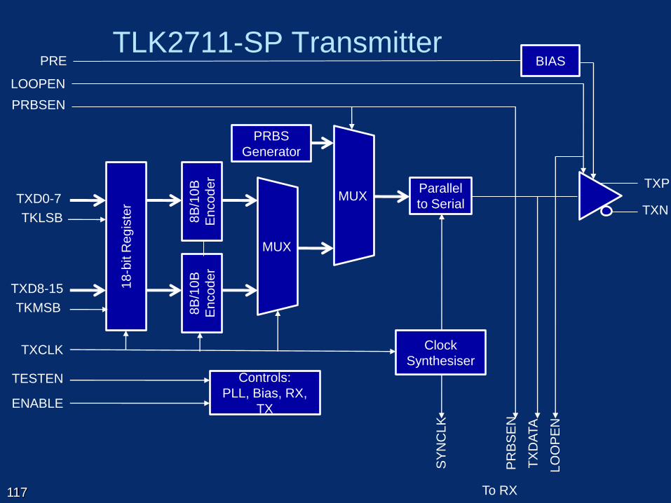
TLK2711-SP Transmitter
117
MUX
PRBS
Generator
TXP
TXN
BIAS PRE
Controls:
PLL, Bias, RX,
TX
TESTEN
ENABLE
To RX
18-b
it R
eg
iste
r TXD0-7
TKLSB
TXD8-15
TKMSB
LOOPEN
TX
DA
TA
LO
OP
EN
PRBSEN
PR
BS
EN
MUX Parallel
to Serial
Clock
Synthesiser TXCLK
SY
NC
LK
8B
/10
B
En
co
de
r
8B
/10
B
En
co
de
r
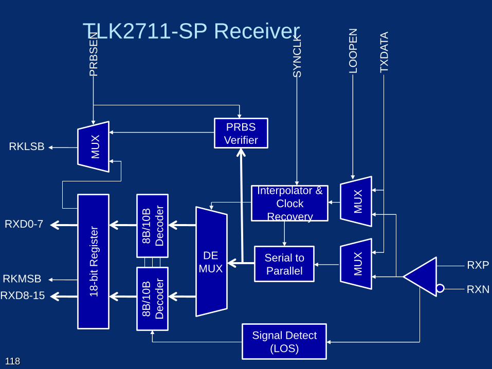
TLK2711-SP Receiver
118
RXP
RXN
LO
OP
EN
TX
DA
TA
Serial to
Parallel MU
X
PRBS
Verifier
PR
BS
EN
1
8-b
it R
egis
ter RXD0-7
RXD8-15
RKMSB
RKLSB
MU
X
Signal Detect
(LOS)
8B
/10
B
Decoder
8B
/10
B
Decoder
DE
MUX
MU
X Interpolator &
Clock
Recovery
SY
NC
LK

TLK2711 Compatibility with SpaceFibre
Bit stream inversion
– TLK2711 does not support bit inversion
– Bit inversion is useful to help PCB layout
– SpaceFibre makes bit inversion mandatory for
new devices
– But permits legacy devices like TLK2711 to not
implement bit inversion
Detecting inversion
– INIT1 and IDLE control words have valid bitwise
inverse symbols
– Can then detect if direct or inverse INIT1’s being
received
– If inverse, change polarity of receiver
119

TLK2711 Compatibility with SpaceFibre
Bit synchronisation
– Bit and symbol synchronisation performed inside
TLK2711
– Status information not provide
– Impact on receive synchronisation state machine
– Now uses reception of valid symbols to indicate
bit and symbol synchronisation
120

TLK2711 Compatibility with SpaceFibre
Symbol synchronisation
– Does not support symbol synchronisation on
negative disparity commas
– Link might never synchronise, depending on data
being sent
121
diff
Comma
-ve
diff
Data
+ve
diff
Data
-ve
diff
Data
+ve
Not Sync’ed
diff
Comma
-ve +ve
diff
Data
same
Data
-ve
same
Data
-ve Disparity
Ones/zeros
Symbol
Not Sync’ed

TLK2711 Compatibility with SpaceFibre
Solution to Symbol Synchronisation
– During initialisation
Use pairs of control words both starting with comma
Comma has +ve or –ve disparity
First control word has only symbols with same number
of 1s and 0s after the comma
122
same
Data
+ve
same
Data
+ve
same
Data
+ve
diff
Comma
+ve
?
Data
-ve
?
Data
?
?
Data
?
diff
Comma
-ve Disparity
Ones/zeros
Symbol
Sync’ed Not Sync’ed
TLK2711 Compatibility with SpaceFibre
Solution to Symbol Synchronisation
– During initialisation
Polarity is not known
INIT1 and IDLE control words have valid bitwise inverse
symbols
These bitwise inverse symbols are chosen to also have
same number of 1s and 0s
So if bit stream is inverted can still synchronise
123

TLK2711 Compatibility with SpaceFibre
Parallel loopback
– Not implemented in TLK2711
– It does provide serial loopback
– SpaceFibre makes parallel loopback optional
– Serial loopback is mandatory
124

TLK2711 Compatibility with SpaceFibre
Interface
– Interface to TLK2711 is 16-bits data + 2 D/K bits
i.e. two symbols wide
– SpaceWire uses control and data words
Four symbols wide
32-bits + 4 D/K bits
– Need to be multiplexed over TLK2711 interface
– SpaceFibre specification permits 8+1, 16+2, or
32+4 wide interfaces to be used
125
TLK2711 Compatibility with SpaceFibre
Error indication
– TLK2711 indicates error detected by receiver by
output of a K0.0 code
– Which is not a valid K-code
– Decoder needed to decode this K-code into an
error signal
126

TLK2711 Compatibility with SpaceFibre
Line drivers and receivers
– TLK2711 uses Voltage Mode Logic (VML)
– SpaceFibre specifies Current Mode Logic (CML)
To improve conducted emissions
– Can translate from VML to CML using resistor
network
127

128
INIT_1
INIT_2
STANDBY
LOS
8B/10B
ENCODER
SERIALISER
DRIVER RECEIVER
DE-SERIALISER
8B/10B
DECODER
SYMBOL
SYNC
RECEIVE
ELASTIC
BUFFER
CLOCK
RECOVERY
MUX
MUX
LANE LAYER
ORDERED SET
EXTRACTION
LANE
INITIALISATION
AND STANDBY
CONTROLLER
RECEIVE
SYNC
STATE MCH.
SYNC
MUX
IDLE
MUX
SKIP
SKIP
INSERTION
COUNTER
8B/10B
ENCODER
8B/10B
DECODER
MUX
10, 20, 40
8+1, 16+2 ,
32+4
32+4 32+4
32+4
32+4
32+4 32+4
10, 20, 40
8+1, 16+2, 32+4
WORD SYNC
MUX
IDLE
ERROR
DECODER
Symbol
Synchronisation
8B/10B Encode/Decode
Word Synchronisation
Encoding Layer
MUX
Lane Initialisation and
Standby Management
Data Rate Adjustment
Lane Control Layer
Parallel Loopback
INVERTER
LoS
Inv Rx
Inv Rx
LoS
Serialisation/
De-Serialisation
Line Driver/Receiver
Serial Loop-Back
Serialisation Layer
Rx Inversion
Lane Interface
SerDes Interface
Serial Interface
Encoding/Decoding Interface
LANE ACTIVE
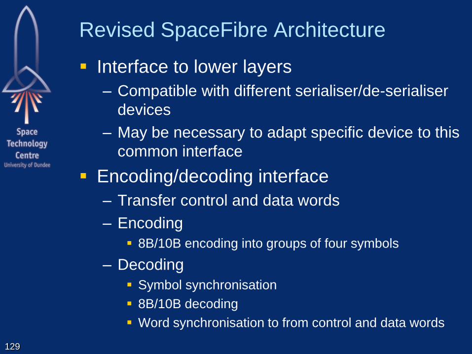
Revised SpaceFibre Architecture
Interface to lower layers
– Compatible with different serialiser/de-serialiser
devices
– May be necessary to adapt specific device to this
common interface
Encoding/decoding interface
– Transfer control and data words
– Encoding
8B/10B encoding into groups of four symbols
– Decoding
Symbol synchronisation
8B/10B decoding
Word synchronisation to from control and data words
129

Conclusions - SpaceFibre Requirements
Compatible with SpaceWire
– At the packet and network levels
High speed
– 2 Gbits/s now (2.5 Gbit/s signalling)
– 5 Gbits/s planned (6.5 Gbits/s signalling)
Very high speed
– Multiple lanes e.g. 4 lanes 8 Gbits/s
Flight quality components
Fibre and copper implementations
100 m optical fibre
5m copper
Low mass cable
130
TBC

Conclusions - SpaceFibre Requirements
FDIR
– Fault detection
Parity/disparity
CRC
– Fault isolation
Galvanic isolation
Data framing – time containment
Virtual channels – bandwidth containment
– Fault recovery
Link level retry
Graceful degradation on lane failure
Babbling idiot protection
Error reporting
131

Conclusions - SpaceFibre Requirements
Support SOIS services
– Packet delivery
– Memory access
– Synchronisation / Time distribution
– Device discovery
– Test
Quality of Service
– Best Effort
– Assured
– Resource Reserved
– Guaranteed
132
TBC
TBC

SpaceFibre Benefits
Sends and receives SpaceWire packets
Virtual channels
– Multiplexes SpaceWire packets over link
– Overcomes SpaceWire router blocking problem
Broadcast messages
– Provides low latency messaging
– Based on an extension of the SpaceWire time-
code mechanism
Coherent quality of service mechanisms
– Bandwidth sharing for payload data-handling
applications
– Deterministic data delivery for command and
control applications 133

Benefits
FDIR support including
– Galvanic isolation
– Fault detection with disparity, CRC, sequence #
– Fault isolation to prevent fault propagation
– Fault recovery to provide rapid recovery from
transient faults
Lanes
– For higher throughput with graceful degradation
– Hot and cold redundancy support
QoS in the CODEC
– Providing inherent robustness against a range of
system errors, like babbling idiots
134

Schedule
Currently simulating in software and OPNET
Presentation December 2011
– SpaceWire Working Group meeting
Draft ECSS standard end January 2012
– Available for Working Group members
Initial review feedback by March 2012
Update to draft standard by May 2012
ECSS standardisation process starts
135

136

Data frame latency when errors occur
137
The additional latency is basically the retransmission time of the frame
with error (256 characters, around 1µs) plus the double of the
transmission delay (say 8-10m, i.e. 2*20 character delay = 2*80ns).
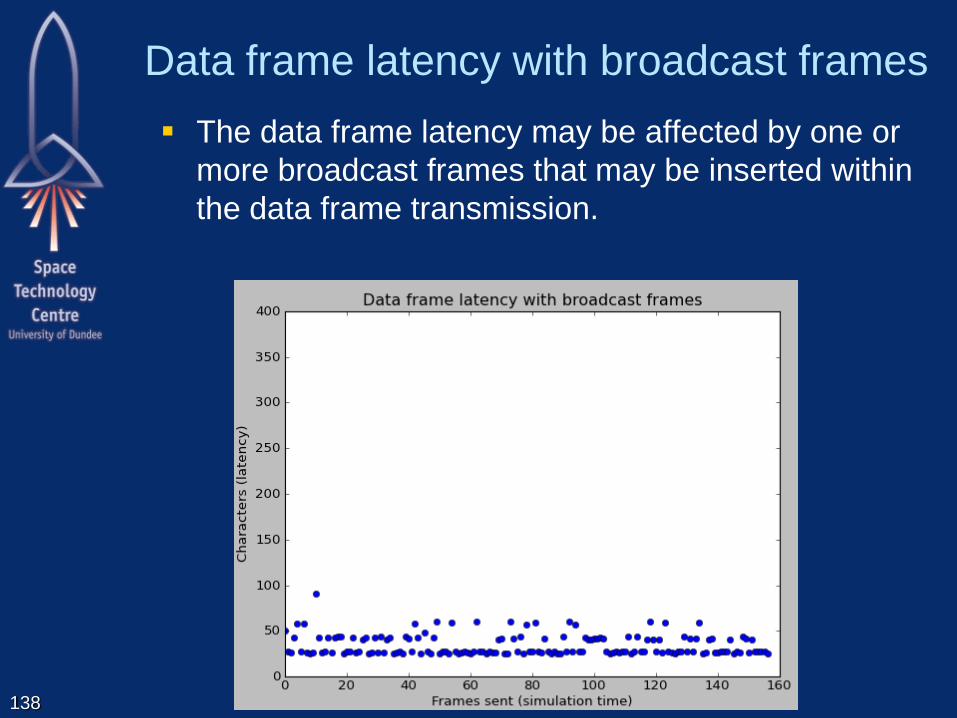
Data frame latency with broadcast frames
138
The data frame latency may be affected by one or
more broadcast frames that may be inserted within
the data frame transmission.

Broadcast frame latency
139
The broadcast frame latency depends on: – The transmission time and line delay
– Jitter introduced by other broadcast frames being sent.


![8PS-WG 3PS-W 3PS-WG 4pS-W 4ps-WG 0.7 2m 4m 5PS-W 5PS-WG 6PS-W 6PS-WG 7PS-W 7PS-WG 2.8 SIZE No. EJECTOR 2PS-W 2PS-WG 0.25(š (L / min) L5PS-WD±åÊ] MPaG 0m 3m 7m 10m 14m 17m 20m 0m](https://static.fdocuments.us/doc/165x107/5b037c037f8b9a2e228c75cb/8ps-wg-3ps-w-3ps-wg-4ps-w-4ps-wg-07-2m-4m-5ps-w-5ps-wg-6ps-w-6ps-wg-7ps-w-7ps-wg.jpg)