Solid Freeform Fabrication 2018: Proceedings of the 29th...
11
BINDER JETTING ADDITIVE MANUFACTURING OF WATER-ATOMIZED IRON I. Rishmawi*, M. Salarian*, and M. Vlasea* *Department of Mechanical and Mechatronics Engineering, University of Waterloo, ON, Canada N2L 3G1 Abstract Binder jetting additive manufacturing (BJAM) was deployed to processing of low-cost, water-atomized pure iron powder. Surface morphology and particle size distribution of the powder were fully characterized using scanning electron microscopy (SEM) and particle dynamic image analysis via Retsch Camsizer X2. Cylindrical samples were fabricated, and in the AM process, the effects of powder compaction, layer thickness and liquid binder level on green part density were studied. Density analysis was performed using x-ray computed tomography (μCT). The potential application and future research work will be outlined based on the characterization results. Key words: Binder jetting, Additive manufacturing, Irregular iron powder, Sintering schedule, Part density Introduction Binder Jetting Additive Manufacturing (BJAM), also known as 3D Printing (3DP), is a powder bed additive manufacturing (AM) process in which powder is spread in layers across a build bed and liquid binding ink is jetted onto each layer. BJAM is a two-step process that goes from initial materials to final part. In the first step, geometrical features of the part are achieved using AM. In the second step, functional features of the parts are achieved via sintering. The process has been predominantly used with ceramics, composites and metals, with metals receiving increasing attention. BJAM of metals has been utilized with iron- based alloys [1–13] for several target applications, such as biomedical implants [3], [6], forging dies [7] and injection molding tools [8,9]. Aside from advantages such as customizability and absence of thermal stresses in printed specimens, BJAM is also a comparatively low-cost process. This is mainly due to the ability to print at room temperature conditions and batch sinter the printed specimens. There has been recent interest in water-atomized powders for BJAM process, which can produce specimens of properties comparable to gas-atomized powders [14,15]. Mostafaei et al. [14] studied the densities and microstructures obtained from water-atomized Inconel 625 specimens and report densities of up to 95% after sintering. Inaekyan et al. [5] characterized density and mechanical properties of water-atomized pure iron specimens, but densities of only around 45% are reported after unassisted sintering. However, the authors performed sintering at 1100°C, which is significantly lower than the melting point of the material [16]. This study focuses on printing BJAM samples with water-atomized iron powder. Apart from feedstock powder characteristics, the most significant process parameters are powder compaction and spreading, layer thickness and liquid binder level. These three parameters are studied to maximize green part density. Subsequently, the impact of sintering on final part density and surface quality is studied. The importance of this work is in bridging the gap between BJAM and large-scale industrial adoption, where inexpensively prepared feedstock powders produce high-quality parts. Experimental Materials The powder used is water-atomized pure iron (AT-1001-HP, Rio Tinto QMP). The powder is sieved to a size range of < 45 μm (USA Standard Test Sieve No. 325, Hogentogler & Co.). Size distribution is characterized (Retsch Camsizer X2) and surface morphology (LEO Field Emission SEM 1530). The powder is blended with polyvinyl alcohol (PVA) powder (Alfa Aesar) that is previously ground and sieved to size range of < 63 μm. The Solid Freeform Fabrication 2018: Proceedings of the 29th Annual International 160 Solid Freeform Fabrication Symposium – An Additive Manufacturing Conference Reviewed Paper
Transcript of Solid Freeform Fabrication 2018: Proceedings of the 29th...
BINDER JETTING ADDITIVE MANUFACTURING OF WATER-ATOMIZED IRON
I. Rishmawi*, M. Salarian*, and M. Vlasea**Department of Mechanical and Mechatronics Engineering, University of Waterloo, ON, Canada N2L 3G1
Abstract Binder jetting additive manufacturing (BJAM) was deployed to processing of low-cost, water-atomized
pure iron powder. Surface morphology and particle size distribution of the powder were fully characterized using scanning electron microscopy (SEM) and particle dynamic image analysis via Retsch Camsizer X2. Cylindrical samples were fabricated, and in the AM process, the effects of powder compaction, layer thickness and liquid binder level on green part density were studied. Density analysis was performed using x-ray computed tomography (µCT). The potential application and future research work will be outlined based on the characterization results.
Key words: Binder jetting, Additive manufacturing, Irregular iron powder, Sintering schedule, Part density
Introduction Binder Jetting Additive Manufacturing (BJAM), also known as 3D Printing (3DP), is a powder bed
additive manufacturing (AM) process in which powder is spread in layers across a build bed and liquid binding ink is jetted onto each layer. BJAM is a two-step process that goes from initial materials to final part. In the first step, geometrical features of the part are achieved using AM. In the second step, functional features of the parts are achieved via sintering. The process has been predominantly used with ceramics, composites and metals, with metals receiving increasing attention. BJAM of metals has been utilized with iron-based alloys [1–13] for several target applications, such as biomedical implants [3], [6], forging dies [7] and injection molding tools [8,9].
Aside from advantages such as customizability and absence of thermal stresses in printed specimens, BJAM is also a comparatively low-cost process. This is mainly due to the ability to print at room temperature conditions and batch sinter the printed specimens. There has been recent interest in water-atomized powders for BJAM process, which can produce specimens of properties comparable to gas-atomized powders [14,15]. Mostafaei et al. [14] studied the densities and microstructures obtained from water-atomized Inconel 625 specimens and report densities of up to 95% after sintering. Inaekyan et al. [5] characterized density and mechanical properties of water-atomized pure iron specimens, but densities of only around 45% are reported after unassisted sintering. However, the authors performed sintering at 1100°C, which is significantly lower than the melting point of the material [16].
This study focuses on printing BJAM samples with water-atomized iron powder. Apart from feedstock powder characteristics, the most significant process parameters are powder compaction and spreading, layer thickness and liquid binder level. These three parameters are studied to maximize green part density. Subsequently, the impact of sintering on final part density and surface quality is studied. The importance of this work is in bridging the gap between BJAM and large-scale industrial adoption, where inexpensively prepared feedstock powders produce high-quality parts.
Experimental Materials The powder used is water-atomized pure iron (AT-1001-HP, Rio Tinto QMP). The powder is sieved to a size
range of < 45 μm (USA Standard Test Sieve No. 325, Hogentogler & Co.). Size distribution is characterized (Retsch Camsizer X2) and surface morphology (LEO Field Emission SEM 1530). The powder is blended with polyvinyl alcohol (PVA) powder (Alfa Aesar) that is previously ground and sieved to size range of < 63 μm. The
Solid Freeform Fabrication 2018: Proceedings of the 29th Annual International
160
Solid Freeform Fabrication Symposium – An Additive Manufacturing ConferenceReviewed Paper
final feedstock blend is 99% iron and 1% PVA by mass. A water-based solvent (ZbTM 60, Z Corporation) is used as a liquid binder in the BJAM process.
AM Process Parameters Printing is accomplished on a ZCorporation 310 Plus binder jetting system (3D Systems). Three AM process
parameters are varied: powder compaction, layer thickness and liquid binder level. Powder compaction is varied by the activation or deactivation of the roller that spreads the powder from the feed bed to the build bed. Layer thickness and liquid binder level are varied through the printer settings. The parameters utilized are summarized in Table 1. Cylindrical specimens measuring 5 mm in diameter and 8 mm in height are printed. Each print batch consists of 16 replicates. The liquid binder level settings are presented in terms of pL/drop, where in terms of the ZPrint software, 70 pL/drop corresponds to 200% saturation level, and 105 pL/drop to 300%. The saturation level physically represents the amount of binder jetted.
Table 1 Summary of process parameters and settings used for the experimental study
Process Parameter Levels Parameter Settings
Roller actuation 2 On, Off Layer thickness (μm) 3 75, 100, 125
Liquid binder level (pL/drop) 2 70, 105
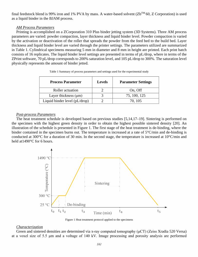
Post-process Parameters The heat treatment schedule is developed based on previous studies [5,14,17–19]. Sintering is performed on
the specimen with the highest green density in order to obtain the highest possible sintered density [20]. An illustration of the schedule is presented in Figure 1. The first stage of the heat treatment is de-binding, where the binder contained in the specimen burns out. The temperature is increased at a rate of 5°C/min and de-binding is conducted at 300°C for a duration of 30 min. In the second stage, the temperature is increased at 10°C/min and held at1490°C for 6 hours.
Figure 1 Heat treatment protocol applied to the specimens
Characterization Green and sintered densities are determined via x-ray computed tomography (μCT) (Zeiss Xradia 520 Versa)
at a voxel size of 5.5 μm and a voltage of 140 kV. Image processing and porosity analysis are performed
161

(Dragonfly Pro v3.3, Object Research Systems Inc.). A photographic representation of a specimen in the green and sintered states is shown in Figure 2.
Figure 2 Specimens as a (a) CAD image, and in the (b) green and (c) sintered states
Shrinkage Dimensional shrinkage in the specimens after sintering is determined through equation (1), where 𝑥𝑥𝐺𝐺is the
measured dimensional feature of a green specimen and 𝑥𝑥𝑆𝑆is that of the specimen after sintering. Geometrical measurements are performed by using digital calipers (Mitutoyo Absolute Digimatic Caliper). Three measurements are taken for each dimension of each specimen, and the measurements are performed at approximately the center of the specimen for both diameter and height.
𝑆𝑆ℎ𝑟𝑟𝑟𝑟𝑟𝑟𝑟𝑟𝑟𝑟𝑟𝑟𝑟𝑟 𝑟𝑟𝑟𝑟 𝑥𝑥 = 𝑥𝑥𝐺𝐺−𝑥𝑥𝑆𝑆𝑥𝑥𝐺𝐺
× 100 (1)
Surface Roughness Surface roughness of green and sintered specimens is measured by using a laser confocal microscope (Keyence
VK-X250). Scans of the side and top surfaces of the specimens are performed. The measurements are taken from approximately the same locations on all specimens for consistency. Scans are performed at a vertical resolution of 1 μm, with a scan area of 1400 μm by 1000 μm.
Results and Discussion
Powder Characterization Powder size analysis results reveal a size distribution of 18 − 54 μm, with a D50 of 34.1 ± 0.5 μm. Powder
sphericity at the D50 size is 0.8. SEM images of the powder are shown in Figure 3. The irregularity and angularity of the particles are visible in the figure.
162

Figure 3 SEM images of the iron powder at magnifications of (a) 200× and (b) 500×
Green Density Analysis Specimen densities are determined through μCT scans and image processing. A consistent voxel size for both
green and sintered specimens is used to ensure consistent analysis. Due to the high voltage used (140 kV), it is assumed that none of the PVA is detected in green specimens, and therefore does not impact the segmentation process. Green densities of all specimen sets are presented in Table 2.
Table 2 Densities of green specimens printed at varying parameter combinations of roller actuation, layer thickness and liquid binder level
Set (Roller, Layer Thickness (µm), Liquid Binder Level (pL/drop))
Green Density (%)
A (ON, 75, 70) 48.1 B (ON, 75, 105) 44.4 C (ON, 100, 70) 35.4 D (ON, 100, 105) 39.9 E (ON, 125, 70) 42.6 F (ON, 125, 105) 38.1 G (OFF, 75, 70) 17.7 H (OFF, 75, 105) 33.7 I (OFF, 100, 70) 35.4 J (OFF, 100, 105) 24.1 K (OFF, 125, 70) 21.2 L (OFF, 125, 105) 27.0
The highest green density obtained is 48.1%, at a layer thickness of 75 μm and a liquid binder level of 70 pL/drop. Based on the results in Table 2, powder compaction through roller actuation is clearly favorable for increasing green density. A powder bed that is more densely packed allows for higher density of the green specimen. The results show that a lower layer thickness leads to higher green densities when the roller is activated. A lower layer thickness corresponds to a tighter packing of the powder in the bed, as the roller spreads a thinner layer of particles an overall larger number of times. Furthermore, a lower liquid binder level leads to higher green densities with the roller activated. The liquid binder takes up space in between powder particles. Hence, minimizing its quantity should increase specimen density, provided that structural integrity of the specimen is maintained. Excessively high levels of liquid binder must be avoided as they might lead to layer shifting, in which individual layers of powder get shifted and results in a slanted specimen. Roller actuation also affects powder
163

spreading. Observations during printing reveal that powder spreading is much less uniform when the roller is deactivated. Streaking and unevenness in spreading are noted, as well as powder clinging to the roller. Generally, layer shifting is occasionally observed when the roller is deactivated, but it is not observed at all when it is activated. Powder spreading and compaction and their optimization are interesting topics of research for future work.
Sintered Density Analysis Sintering is performed on the specimen set producing the highest green density, namely, specimen A. A
sintered density of 91.3% is obtained. Image processing analysis on the μCT scans reveals the distribution of porosity after sintering. Three-dimensional renders of the specimen in the green and sintered states are illustrated in Figure 4.
Figure 4 Three-dimensional renders of the samples in the (a) green and (b) sintered (1490°C) states.
The final sintered density value of 91.3% shows that BJAM of water-atomized iron powder can produce high density parts while preserving shape fidelity for simple, symmetric shapes. The high temperature and duration used promotes aggressive sintering and densification by the formation of sinter necks among powder particles. Higher densities are expectedly attainable if longer sintering durations were used. Sinter neck formation reduces the total energy of the thermodynamic system, which is the driving force, and the reduction in energy is higher for a smaller powder particle size [20]. Sintering progresses once an activation barrier is crossed, whereby volumetric diffusion is the major densification mechanism at such a high temperature [20]. The activation barrier for pure iron is between 1000°C and 1200°C [21]. Maintaining the sintering environment for longer durations at a constant temperature that is beyond the activation barrier promotes sinter neck formation. Thus, it is possible to select a sintering temperature that is between 1200°C and the melting point, and increase the sintering duration as long as needed in order to obtain the maximum desired part density. At such a temperature, sintering will progress and only cede when the total energy of the system is reduced to the minimum.
The results presented in this study are comparable to those presented by Inaekyan et al. [5]. In their work, the authors deploy a powder material identical to that used in this work, but with a size distribution of 15 to 51 µm.
164

The sintering schedule resembles an industrial Powder Metallurgy schedule, whereby de-binding is performed at 195°C for 6 hours, and sintering at 1100°C for 2 hours in a pure argon atmosphere. The authors report green and sintered densities of ~40% and ~45% respectively. The final sintered density result is drastically different to what is obtained in our work. This difference underscores the importance of the sintering schedule. As discussed, the sintering to high densities occurs by crossing the activation barrier and maintaining the temperature for longer and longer durations. Sintering at a lower temperature would require longer durations to achieve high densities. The sintering atmosphere also plays a role, where the introduction of hydrogen as a reducing agent aids in preventing oxide layer formation, which would hinder sintering.
Porosity distribution is presented as a color map in Figure 5, showing the 91.3% density sintered specimen from the side and top. Sintering to the density of 91.3% results in the absence of an interconnected pore network, where instead pores are isolated inside the specimen and not connected to the external air. Pore volumes in the range of 4.32×103 μm3 to 0.007 mm3 comprise the majority of porosity in the specimen. Larger pores are almost exclusively present in the topmost region of the specimen, while medium-sized pores are interspersed in the central region of specimen. Smaller pores are distributed throughout the whole specimen, with lower concentrations in the bottommost region. These observations are indicative of powder packing effects, where powder at the bottom of the bed is repeatedly compacted such that low porosity is obtained in the specimen bottom. Furthermore, pore distribution in the horizontal direction (perpendicular to the build direction) is uneven. Both small and large pores are located more preferentially toward one side than the other, which is an indication of a build orientation effect. Specifically, powder spreading might lead to preferential packing, where the one end of the build bed gets more powder than the other end and hence better packing.
Figure 5 Three-dimensional and top-view flattened images of the cylindrical specimen sintered at 1490°C, obtained via μCT scans. The distribution of pores by volume is shown as a color map.
The work of this paper shows that high densities are attainable with water-atomized pure iron powder in a BJAM system. However, the necessary next step is the creation of a comprehensive and reliable “map” that allows
165

predictive control over sintering parameters to achieve pre-determined densities. This can be achieved through a Master Sinter Curve (MSC) [20]. The MSC would allow appropriate sintering schedules to be selected in order to obtain densities over 90% relevant to metal component production, but at lower temperatures than the temperature presented in this work (1490 °C) and at the cost of longer sintering durations. Furnaces of lower temperature with environment gas control are economical and generally preferred by industry.
Shrinkage and Surface Roughness Analysis Shrinkage induced on specimen A upon sintering is quantified by comparing the major and minor diameters
of the cylinders a and b and height h before and after sintering. Shrinkage calculations are presented based on calipers measurements and illustrated in Figures 6 and 7. The shrinkage analysis shows that high shrinkage in all dimensions is observed. Shrinkage in a and b is 25.3 ± 2.8% and 24.2 ± 2.1% respectively, while in h it is 24.8 ± 3.5%. Furthermore, based on the CT data, shrinkage in a is 24.86 ± 1.37%, in b is 24.37 ± 2.42%, and in h it is 25.31 ± 2.37%. Shrinkage is relatively uniform among the three dimensions, which indicates that shape fidelity is conserved for these simple, symmetric shapes despite the large reduction in volume.
Figure 6 Visual illustration of shrinkage from the (a) green and (b) sintered samples
166
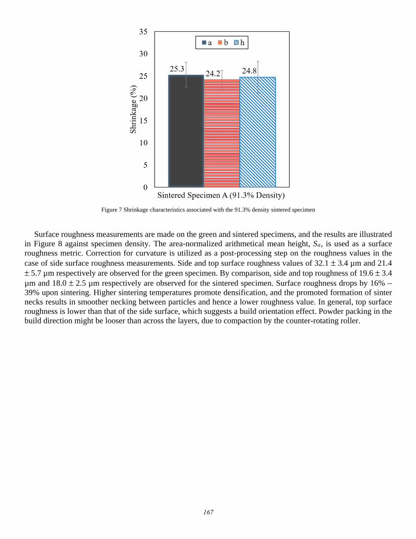
Figure 7 Shrinkage characteristics associated with the 91.3% density sintered specimen
Surface roughness measurements are made on the green and sintered specimens, and the results are illustrated in Figure 8 against specimen density. The area-normalized arithmetical mean height, Sa, is used as a surface roughness metric. Correction for curvature is utilized as a post-processing step on the roughness values in the case of side surface roughness measurements. Side and top surface roughness values of 32.1 ± 3.4 µm and 21.4 ± 5.7 µm respectively are observed for the green specimen. By comparison, side and top roughness of 19.6 ± 3.4µm and 18.0 ± 2.5 µm respectively are observed for the sintered specimen. Surface roughness drops by 16% −39% upon sintering. Higher sintering temperatures promote densification, and the promoted formation of sinternecks results in smoother necking between particles and hence a lower roughness value. In general, top surfaceroughness is lower than that of the side surface, which suggests a build orientation effect. Powder packing in thebuild direction might be looser than across the layers, due to compaction by the counter-rotating roller.
167

Figure 8 Surface roughness plotted against density for green and sintered specimens
In summary, this study shows that in-process parameters can be controlled in order to maximize green density, and sintering has an impact on porosity distribution, particularly in terms of interconnected porosity, and surface qualities. In-process and post-process parameters can be carefully selected to suit the application requirement and attain the required final density.
Conclusions
Water-atomized pure iron powder was deployed in a commercial BJAM system and subsequently subjected to a sintering heat treatment in order examine the possible densities attainable. Green density can be increased by reducing layer thickness and liquid binder level. Powder compaction has an important effect on powder spreading and packing in the bed, and optimization of powder spreading is a topic of future research. Sintering at a high temperature close to the melting point and for long durations can achieve densities up to 91.3%, and increasing sintering time is expected to produce even higher densities. In the context of industrial applications, high densities are expected to be attainable by sintering at lower temperatures but for extended durations, in industrial furnaces. The creation of a Master Sinter Curve is an important next step to allow predictive tailoring of densities. Shrinkage induced upon sintering is large, although it is uniform and shape fidelity is well-conserved. Aggressive densification during sintering generally enhances surface quality of printed parts.
Acknowledgements
This work was supported by funding from the Federal Economic Development Agency for Sothern Ontario (FedDev Ontario), in partnership with Rio Tinto. The authors would like to acknowledge the contribution of Rio Tinto for their support and mentorship throughout the completion of work.
168
References [1] Y. Tang, Y. Zhou, T. Hoff, M. Garon, Y.F. Zhao, Elastic modulus of 316 stainless steel lattice structure
fabricated via binder jetting process, Materials Science and Technology. 32 (2016) 648–656.doi:10.1179/1743284715Y.0000000084.
[2] R. Frykholm, Y. Takeda, B.-G. Andersson, R. CarlströM, Solid State Sintered 3-D Printing Component byUsing Inkjet (Binder) Method, Journal of the Japan Society of Powder and Powder Metallurgy. 63 (2016)421–426. doi:10.2497/jjspm.63.421.
[3] M. Dourandish, D. Godlinski, A. Simchi, 3D Printing of Biocompatible PM-Materials, Materials ScienceForum. 534–536 (2007) 453–456. doi:10.4028/www.scientific.net/MSF.534-536.453.
[4] T. Do, C.S. Shin, D. Stetsko, G. VanConant, A. Vartanian, S. Pei, P. Kwon, Improving Structural Integritywith Boron-based Additives for 3D Printed 420 Stainless Steel, Procedia Manufacturing. 1 (2015) 263–272. doi:10.1016/j.promfg.2015.09.019.
[5] K. Inaekyan, V. Paserin, I. Bailon-Poujol, V. Brailovski, Binder-jetting additive manufacturing with wateratomized iron powders, (n.d.) 7.
[6] D.-T. Chou, D. Wells, D. Hong, B. Lee, H. Kuhn, P.N. Kumta, Novel processing of iron–manganese alloy-based biomaterials by inkjet 3-D printing, Acta Biomaterialia. 9 (2013) 8593–8603.doi:10.1016/j.actbio.2013.04.016.
[7] K. Agarwal, D. Mathur, R. Shivpuri, J. Lembo, [SS 316 & 420+ BJ] Evaluation of ProMetal technique forapplication to dies for short run forgings, Solid Freeform Fab. Proceedings, Austin, TX. (2002) 376–83.
[8] E. Sachs, E. Wylonis, S. Allen, M. Cima, H. Guo, Production of injection molding tooling with conformalcooling channels using the three dimensional printing process, Polymer Engineering & Science. 40 (2000)1232–1247. doi:10.1002/pen.11251.
[9] S.M. Allen, E.M. Sachs, Three-dimensional printing of metal parts for tooling and other applications,Metals and Materials. 6 (2000) 589–594. doi:10.1007/BF03028104.
[10] E.A. Rojas-Nastrucci, J. Nussbaum, T.M. Weller, N.B. Crane, Meshed rectangular waveguide for highpower, low loss and reduced weight applications, in: IEEE, 2016: pp. 1–4.doi:10.1109/MWSYM.2016.7540079.
[11] C.B. Williams, J.K. Cochran, D.W. Rosen, Additive manufacturing of metallic cellular materials via three-dimensional printing, The International Journal of Advanced Manufacturing Technology. 53 (2011) 231–239. doi:10.1007/s00170-010-2812-2.
[12] M. Ziaee, E.M. Tridas, N.B. Crane, Binder-Jet Printing of Fine Stainless Steel Powder with Varied FinalDensity, JOM. 69 (2017) 592–596. doi:10.1007/s11837-016-2177-6.
[13] D. Godlinski, S. Morvan, Steel Parts with Tailored Material Gradients by 3D-Printing Using Nano-Particulate Ink, Materials Science Forum. 492–493 (2005) 679–684.doi:10.4028/www.scientific.net/MSF.492-493.679.
[14] A. Mostafaei, J. Toman, E.L. Stevens, E.T. Hughes, Y.L. Krimer, M. Chmielus, Microstructural evolutionand mechanical properties of differently heat-treated binder jet printed samples from gas- and water-atomized alloy 625 powders, Acta Materialia. 124 (2017) 280–289. doi:10.1016/j.actamat.2016.11.021.
[15] C.T. Schade, T.F. Murphy, C. Walton, DEVELOPMENT OF ATOMIZED POWDERS FOR ADDITIVEMANUFACTURING, (n.d.) 11.
[16] D. R. Askeland, P. P. Fulay, and W. J. Wright. The science and engineering of materials 6th edition,Cengage learning Inc, 2010, pp. 889.
[17] A. Basalah, Y. Shanjani, S. Esmaeili, E. Toyserkani, Characterizations of additive manufactured poroustitanium implants, Journal of Biomedical Materials Research Part B: Applied Biomaterials. 100B (2012)1970–1979. doi:10.1002/jbm.b.32764.
[18] M. Vlasea, R. Pilliar, E. Toyserkani, Control of structural and mechanical properties in bioceramic bonesubstitutes via additive manufacturing layer stacking orientation, Additive Manufacturing. 6 (2015) 30–38.doi:10.1016/j.addma.2015.03.001.
[19] M. Vlasea, E. Toyserkani, R. Pilliar, Effect of Gray Scale Binder Levels on Additive Manufacturing ofPorous Scaffolds with Heterogeneous Properties, International Journal of Applied Ceramic Technology.12 (2015) 62–70. doi:10.1111/ijac.12316.
169

[20] E. Wheat, Process Mapping and Optimization of Titanium Parts Made by Binder Jetting AdditiveManufacturing, MASc thesis, University of Waterloo, 2018.
[21] P. S. Liu and G. F. Chen, Making porous metals, in: Porous Materials: Processing and Applications,Elsevier, 2014, pp. 21 – 112. https://www.sciencedirect.com/science/article/pii/B9780124077881000022(accessed June 26, 2018).
170