Solid Edge sheet metal design -...
232
Transcript of Solid Edge sheet metal design -...


Proprietary and restricted rights notice
This software and related documentation are proprietary to Siemens ProductLifecycle Management Software Inc.
© 2012 Siemens Product Lifecycle Management Software Inc. All Rights Reserved.
Siemens and the Siemens logo are registered trademarks of Siemens AG. Solid Edgeis a trademark or registered trademark of Siemens Product Lifecycle ManagementSoftware Inc. or its subsidiaries in the United States and in other countries. Allother trademarks, registered trademarks or service marks belong to their respectiveholders.
2 Solid Edge sheet metal design spse01546

Contents
Proprietary and restricted rights notice . . . . . . . . . . . . . . . . . . . . . . . . . 2
Introduction . . . . . . . . . . . . . . . . . . . . . . . . . . . . . . . . . . . . . . . . . . . . . . 1-1
Course Overview . . . . . . . . . . . . . . . . . . . . . . . . . . . . . . . . . . . . . . . . . . . 2-1
Sheet metal overview and definitions . . . . . . . . . . . . . . . . . . . . . . . . . . . 3-1
Terminology . . . . . . . . . . . . . . . . . . . . . . . . . . . . . . . . . . . . . . . . . . . . . . . . 3-2Material Table command . . . . . . . . . . . . . . . . . . . . . . . . . . . . . . . . . . . . . . . 3-3Gage tab . . . . . . . . . . . . . . . . . . . . . . . . . . . . . . . . . . . . . . . . . . . . . . . . . . 3-6Activity: Starting sheet metal design . . . . . . . . . . . . . . . . . . . . . . . . . . . . . . 3-7Lesson review . . . . . . . . . . . . . . . . . . . . . . . . . . . . . . . . . . . . . . . . . . . . . . . 3-12Lesson summary . . . . . . . . . . . . . . . . . . . . . . . . . . . . . . . . . . . . . . . . . . . . 3-13
Base Features . . . . . . . . . . . . . . . . . . . . . . . . . . . . . . . . . . . . . . . . . . . . . 4-1
Construct the base feature . . . . . . . . . . . . . . . . . . . . . . . . . . . . . . . . . . . . . . 4-1Tab command . . . . . . . . . . . . . . . . . . . . . . . . . . . . . . . . . . . . . . . . . . . . . . 4-4Construct a tab . . . . . . . . . . . . . . . . . . . . . . . . . . . . . . . . . . . . . . . . . . . . . . 4-6Cut command . . . . . . . . . . . . . . . . . . . . . . . . . . . . . . . . . . . . . . . . . . . . . . 4-9Activity: Using regions to create tabs and cuts . . . . . . . . . . . . . . . . . . . . . . . 4-13Lesson review . . . . . . . . . . . . . . . . . . . . . . . . . . . . . . . . . . . . . . . . . . . . . . . 4-25Lesson summary . . . . . . . . . . . . . . . . . . . . . . . . . . . . . . . . . . . . . . . . . . . . 4-25
Contour Flange . . . . . . . . . . . . . . . . . . . . . . . . . . . . . . . . . . . . . . . . . . . . 5-1
Contour Flange command . . . . . . . . . . . . . . . . . . . . . . . . . . . . . . . . . . . . . . 5-2Examples: Defining Reference Plane Orientation to Construct a ContourFlange . . . . . . . . . . . . . . . . . . . . . . . . . . . . . . . . . . . . . . . . . . . . . . . . . . 5-2Activity: Constructing a base feature using contour flange . . . . . . . . . . . . . . . 5-3Lesson review . . . . . . . . . . . . . . . . . . . . . . . . . . . . . . . . . . . . . . . . . . . . . . . 5-17Lesson summary . . . . . . . . . . . . . . . . . . . . . . . . . . . . . . . . . . . . . . . . . . . . 5-17
Flanges, corners and bend relief . . . . . . . . . . . . . . . . . . . . . . . . . . . . . . . 6-1
Creating flanges . . . . . . . . . . . . . . . . . . . . . . . . . . . . . . . . . . . . . . . . . . . . . 6-2Flange command . . . . . . . . . . . . . . . . . . . . . . . . . . . . . . . . . . . . . . . . . . . . 6-2Corner Relief . . . . . . . . . . . . . . . . . . . . . . . . . . . . . . . . . . . . . . . . . . . . . . . 6-5Bend command . . . . . . . . . . . . . . . . . . . . . . . . . . . . . . . . . . . . . . . . . . . . . 6-5Insert a bend . . . . . . . . . . . . . . . . . . . . . . . . . . . . . . . . . . . . . . . . . . . . . . . 6-6Close 2-Bend Corner command . . . . . . . . . . . . . . . . . . . . . . . . . . . . . . . . . . 6-9Activity: Flange and corner conditions . . . . . . . . . . . . . . . . . . . . . . . . . . . . . 6-10Lesson review . . . . . . . . . . . . . . . . . . . . . . . . . . . . . . . . . . . . . . . . . . . . . . . 6-33Lesson summary . . . . . . . . . . . . . . . . . . . . . . . . . . . . . . . . . . . . . . . . . . . . 6-33
Hem . . . . . . . . . . . . . . . . . . . . . . . . . . . . . . . . . . . . . . . . . . . . . . . . . . . . . 7-1
spse01546 Solid Edge sheet metal design 3

Contents
Hem command . . . . . . . . . . . . . . . . . . . . . . . . . . . . . . . . . . . . . . . . . . . . . 7-1Construct a hem . . . . . . . . . . . . . . . . . . . . . . . . . . . . . . . . . . . . . . . . . . . . . 7-2Activity: Using the hem command in sheet metal design . . . . . . . . . . . . . . . . 7-3Lesson review . . . . . . . . . . . . . . . . . . . . . . . . . . . . . . . . . . . . . . . . . . . . . . . 7-8Lesson summary . . . . . . . . . . . . . . . . . . . . . . . . . . . . . . . . . . . . . . . . . . . . 7-8
Using live rules in sheet metal . . . . . . . . . . . . . . . . . . . . . . . . . . . . . . . . 8-1
Working with Live Rules . . . . . . . . . . . . . . . . . . . . . . . . . . . . . . . . . . . . . . . 8-1Thickness chain . . . . . . . . . . . . . . . . . . . . . . . . . . . . . . . . . . . . . . . . . . . . . 8-6Copying, pasting, and attaching sheet metal features . . . . . . . . . . . . . . . . . . . 8-7Activity: Using live rules in sheet metal . . . . . . . . . . . . . . . . . . . . . . . . . . . . 8-13Lesson review . . . . . . . . . . . . . . . . . . . . . . . . . . . . . . . . . . . . . . . . . . . . . . . 8-29Lesson summary . . . . . . . . . . . . . . . . . . . . . . . . . . . . . . . . . . . . . . . . . . . . 8-30
Jog . . . . . . . . . . . . . . . . . . . . . . . . . . . . . . . . . . . . . . . . . . . . . . . . . . . . . . 9-1
Jog command . . . . . . . . . . . . . . . . . . . . . . . . . . . . . . . . . . . . . . . . . . . . . . 9-1Editing the bend radius . . . . . . . . . . . . . . . . . . . . . . . . . . . . . . . . . . . . . . . . 9-2Activity: Using the jog and break corner command in sheet metal design . . . . . 9-6Lesson review . . . . . . . . . . . . . . . . . . . . . . . . . . . . . . . . . . . . . . . . . . . . . . . 9-21Lesson summary . . . . . . . . . . . . . . . . . . . . . . . . . . . . . . . . . . . . . . . . . . . . 9-21
Deformation features . . . . . . . . . . . . . . . . . . . . . . . . . . . . . . . . . . . . . . 10-1
Adding sheet metal deformation features . . . . . . . . . . . . . . . . . . . . . . . . . . . 10-1Louver command . . . . . . . . . . . . . . . . . . . . . . . . . . . . . . . . . . . . . . . . . . . 10-14Dimple command . . . . . . . . . . . . . . . . . . . . . . . . . . . . . . . . . . . . . . . . . . . 10-15Drawn Cutout command . . . . . . . . . . . . . . . . . . . . . . . . . . . . . . . . . . . . . . 10-15Bead command . . . . . . . . . . . . . . . . . . . . . . . . . . . . . . . . . . . . . . . . . . . . 10-17Gusset command . . . . . . . . . . . . . . . . . . . . . . . . . . . . . . . . . . . . . . . . . . . 10-18Working with feature origins . . . . . . . . . . . . . . . . . . . . . . . . . . . . . . . . . . . 10-19Activity: Deformation Features . . . . . . . . . . . . . . . . . . . . . . . . . . . . . . . . . 10-20Lesson review . . . . . . . . . . . . . . . . . . . . . . . . . . . . . . . . . . . . . . . . . . . . . . 10-47Lesson summary . . . . . . . . . . . . . . . . . . . . . . . . . . . . . . . . . . . . . . . . . . . 10-47
Creating flat patterns . . . . . . . . . . . . . . . . . . . . . . . . . . . . . . . . . . . . . . 11-1
Flattening sheet metal parts . . . . . . . . . . . . . . . . . . . . . . . . . . . . . . . . . . . . 11-1Construct a flat pattern in the sheet metal part document . . . . . . . . . . . . . . 11-12Flatten command . . . . . . . . . . . . . . . . . . . . . . . . . . . . . . . . . . . . . . . . . . . 11-13Save As Flat command . . . . . . . . . . . . . . . . . . . . . . . . . . . . . . . . . . . . . . . 11-14Activity: Creating a flat pattern from a sheet metal part . . . . . . . . . . . . . . . 11-15Lesson review . . . . . . . . . . . . . . . . . . . . . . . . . . . . . . . . . . . . . . . . . . . . . . 11-21Lesson summary . . . . . . . . . . . . . . . . . . . . . . . . . . . . . . . . . . . . . . . . . . . 11-22
4 Solid Edge sheet metal design spse01546

Lesson
1 Introduction
Welcome to Solid Edge self-paced training. This course is designed to educate youin the use of Solid Edge. The course is self-paced and contains instruction followedby activities.
Solid Edge self-paced courses• spse01424—Working with Solid Edge Embedded Client
• spse01510—Sketching
• spse01515—Constructing base features
• spse01520—Moving and rotating faces
• spse01525—Working with face relationships
• spse01530—Constructing treatment features
• spse01535—Constructing procedural features
• spse01536—Modeling synchronous and ordered features
• spse01537—Multi-body modeling
• spse01540—Modeling assemblies
• spse01545—Creating detailed drawings
• spse01546—Sheet metal design
• spse01550—Practicing your skills with projects
• spse01560—Modeling a Part Using Surfaces
• spse01610—Solid Edge frame design
• spse01640—Assembly patterning
• spse01645—Assembly systems libraries
• spse01650—Working with large assemblies
• spse01655—Revising assemblies
• spse01660—Assembly reports
spse01546 Solid Edge sheet metal design 1-1

Lesson 1 Introduction
• spse01665—Replacing parts in an assembly
• spse01670—Designing in the context of an assembly
• spse01675—Assembly features
• spse01680—Inspecting assemblies
• spse01685—Alternate assemblies
• spse01686—Adjustable parts and assemblies
• spse01690—Virtual components in assemblies
• spse01691—Exploding assemblies
• spse01692—Rendering assemblies
• spse01693—Animating assemblies
• spse01695—XpresRoute (tubing)
• spse01696—Creating a Wire Harness with Harness Design
• spse01697—Working with nailboards
• spse01698—Using a cam relationship
Start with the tutorials
Self-paced training begins where tutorials end. Tutorials are the quickest way foryou to become familiar with the basics of using Solid Edge. If you do not have anyexperience with Solid Edge, please start by working through the tutorials for basicpart modeling and editing before starting self-paced training.
Supported Browsers
• Windows:
o Internet Explorer 8 or 9
o Firefox 12 or higher
• UNIX/Linux
o Firefox 9.x or higher*
• Mac: Safari 5.x or higher
Java Plug In Required for search
The search engine requires version 1.6.0 or higher of the Java Plug In installed toyour browser. The plug in is available (free) in the Java Runtime Environment (JRE)6.0. If you need to install the JRE, or an equivalent Java environment, visit the Javadownload site at http://www.java.sun.com.
1-2 Solid Edge sheet metal design spse01546

Introduction
Adobe Flash Player required for videos and simulations
To watch videos and simulations, you must have the Adobe Flash Player version 10or later installed as a plugin to your browser. You can download the Flash Player(free) at the http://get.adobe.com/flashplayer
Adobe Acrobat Reader
Some portions of hte help may be delivered as PDF which requires AdobeAcrobat Reader 7.0 or higher. You can download the reader (free) fromhttp://get.adobe.com/reader/
Internet Explorer Caveats
• IE9 Compatibility View. The HTML deliverables are fully supported whenlaunched with the http:// protocol or the file:/// protocol. However, if you areviewing the files from a local installation e.g, D:// ,you may need to enableCompatibility View. In IE 9, do the following:
1. Choose Tools/Compatibility View Settings.
2. In the Compatibility View Settings dialog box, select the “Display allwebsites” in Compatibility View check box.
*Firefox Caveats
• Firefox recommends that users update the latest version for security issuessurrounding Java. They do not recommend using older versions of Firefox due tothese issues. See: http://support.mozilla.org/en-US/kb/latest-firefox-issues
• Most customers install and launch our deliverables via http:// protocol which isfully supported. However, Firefox has a default security setting that preventsthe help from launching correctly from a UNC path (file:///). To change thissetting, you need to change the value of the security.fileuri.strict_origin_policypreference:
o In the address bar, type about:config.
o In the Filter field, type security.fileuri, if the value of thesecurity.fileuri.strict_origin_policy preference is set to true, set the value tofalse. (Double-clicked the value to toggle it.)
o Restart the browser.
spse01546 Solid Edge sheet metal design 1-3


Lesson
2 Course Overview
Course overview
The Solid Edge Sheet Metal application is specialized for modeling straight brakesheet metal parts.
Once you complete the activities in this course, you will be able to:
• Set parameters for sheet metal, such as bend radius and material thickness.
• Place and manipulate flanges and bends.
• Specify sheet metal treatments and corner parameters.
• Place holes, cutouts, dimples, louvers, beads, gussets.
• Modify geometry using live rules for synchronous design.
• Prepare the sheet metal geometry for downstream manufacturing processessuch as creating a flat pattern.
spse01546 Solid Edge sheet metal design 2-1


Lesson
3 Sheet metal overview anddefinitions
Sheet metal overview
Sheet metal design is governed by the premise that the raw material used to forma sheet metal part is of common stock and of uniform thickness. The sheet metalpart is designed in the formed state, but in the manufacturing process, many of thefeatures of the part will be applied to the part before bending. The final locations ofthese features on the formed part is dependant on how the material behaves duringthe bending process. Material may stretch as the elastic limit is exceeded duringbending and, while this stretching may be negligible in the final positioning of thefeature, it may also make the target position after bending be incorrectly located.
The stretching of material during bending varies based on the material used andthe thickness of the material. To correctly accommodate the stretching of material,calculations are made using a standard bend formula, which is provided. This bendformula can be customized for each stock material and by doing so, better accuracy isachieved in the resulting parts.
spse01546 Solid Edge sheet metal design 3-1

Lesson 3 Sheet metal overview and definitions
Terminology
Sheet metal features
1. Plate: Consists of a layer face and a thickness face.
2. Tab-Flange: Two plates connected by a bend.
3. Bend: Connects two tab-flanges.
4. Bend Relief: Option to prevent tearing during bending.
5. Cutouts: Openings in the part.
6. Corner: Where 2 or 3 bends meet.
7. Procedural Feature: Deformation features such as dimples, drawn cutouts,louvers, beads, gussets, and so forth.
3-2 Solid Edge sheet metal design spse01546

Sheet metal overview and definitions
Steering wheel behavior in sheet metal
When you select a thickness face, Solid Edge displays a steering wheel unique tothe sheet metal application. You can create flanges by selecting the flange starthandle. You can use the primary axis, parallel to the layer face, to manipulate thesize of the plate.
(1) Primary Axis: Used to move or rotate the thickness face.
(2) Origin
(3) Flange start handle: This opens flange creation options on the command bar.
When you move the steering wheel origin, all of the steering wheel capabilitiesbecome accessible.
Material Table commandDefines the material and mechanical properties for a part. When you select amaterial from the list, material and mechanical properties for the material suchas face style, fill style, density, coefficient of thermal expansion, and so forth areassigned.
spse01546 Solid Edge sheet metal design 3-3
Lesson 3 Sheet metal overview and definitions
You can use the Solid Edge Material Table dialog box to do the following:
• Create, edit, and delete material property sets which are stored in the materiallibrary property file, material.mtl.
• Assign an existing material to the current document.
• Create a local material for use only in the current document.
The material and mechanical properties are used when you calculate the physicalproperties for a part or assembly, place the part in an assembly, render the assemblywith Advanced Rendering, create a parts list on a drawing, define a bill of materials,and so forth.
When working with a sheet metal part, you also use the material table to definethe properties for the sheet metal stock you are using, such as material thickness,bend radius, and so forth.
Material Library Property file
The material names and property sets are stored in an external material databasefile, material.mtl. The material.mtl file is used to populate the property set for eachmaterial on the Solid Edge Material Table dialog box. You can use these materialsto define a material for any document on your computer, or other computers onyour network.
You can use the Add To Library, Update In Library, and Delete From Library buttonsto create, edit, and delete a material from the material.mtl file.
By default, the file is located in the Solid Edge ST5 Program folder. You can instructSolid Edge to look for the material.mtl file in a different folder, including a folderon another machine on the network. This makes it easy for all your users to workwith a consistent set of materials and properties while providing the capabilityto customize the materials list.
To define a new location for the material.mtl file, from the Application menu,choose Solid Edge Options® File Locations, select the Material Table entry, thenclick Modify. On the Browse dialog box, specify the drive and folder containing thematerial.mtl file. After specifying the location, click Update.
Note You can use the Prompt For Material In New Model Documents option on theGeneral tab of the Options dialog box to control whether you are prompted toassign a material when creating a new document.
3-4 Solid Edge sheet metal design spse01546

Sheet metal overview and definitions
Defining a local materialYou can create one local material name and property set for a document. Thiscan be useful when you need a variation of a common material to be displayed inthe Material column in a parts list, bill of materials, or in Property Manager. Forexample, when using steel or aluminum structural shapes, you may want the shapeinformation as part of the material name for the current part, but you do not wantto add the shape information to the material.mtl file.
Type the new name and properties you want in the Solid Edge Material Tabledialog box, then click the Apply To Model button. The material is then applied toonly the current part, and the material.mtl file, located in the Solid Edge Programfolder, is not updated.
Sheet metal gagesThe sheet metal gage indicates the standard thickness of the sheet metal for aspecific material. In Solid Edge, you can store sheet metal gage information in thematerial library or in a Microsoft Excel file.
Sheet metal gage information stored in an Excel file is stored in a gage table, whichis simply a sheet within the Excel file that contains information, such as the gagename, material thickness, and bend radius. Solid Edge delivers a default gage file,Gagetable.xls, to the Solid Edge ST5 Program folder.
Gage tables can be very useful when defining the sheet metal gage. For example,suppose you have different materials with the same gage, but different materialthickness or perhaps you have the same material with the same material thickness,but different bend attributes. Since the gage table is simply a sheet in the Excelfile, to create additional gage tables to accommodate your different gage attributecombinations, all you have to do is insert a new sheet that contains the appropriategage information. If you want to add a new gage to the gage table, you can copy andpaste an existing gage, and then modify the information in the new gage.
Note To ensure all changes are saved, ensure that you close the Excel file beforeclosing the Material Table dialog box.
After you have created the gage table and gages, you can use the Associate GageTable option on the Material Table dialog box to map the gage table and gage to amaterial or document. Once you select a material and the gage information you wantto map, you can click the Update in Library button to add the gage information tothe material library. For more information, see Map a gage file and gage table to amaterial or document.
When working with Gage tables, you should be careful when specifying theinformation about the table. If problems do occur, Solid Edge provides a numberof error messages to help you resolve the issue. For example, Solid Edge verifiesinformation such as:
• The path for the gage table file.
• The availability of the gage table worksheet.
• The gage parameters found in the gage table.
• Changes made to the Excel file since the last time the sheet metal file wasaccessed.
• The validity of values entered for parameters like Material Thickness or BendRadius.
spse01546 Solid Edge sheet metal design 3-5

Lesson 3 Sheet metal overview and definitions
Gage tabUse Excel FileSpecifies that you want to get the gage information from an Excel file. You canuse the Browse button to specify the Excel file you want to use.
Use Gage TableSpecifies the name of the gage table. You can use the Edit button to open theExcel file for edit.
Sheet Metal GageDisplays the name of the current gage. When you select a name from the list, aset of associated material and mechanical properties is displayed. You can usethe tabs on the dialog box to review or modify the properties. You can also definethe material thickness using the Material Thickness option on the Gage tab.
Material ThicknessSpecifies the material thickness for the part.
Bend RadiusSpecifies the bend radius value for the part.
To facilitate creation of flat patterns, Solid Edge always creates a minimum bendradius for features that can be flattened, even if you specify a bend radius valueof zero (0.00). For metric documents, a zero bend radius will actually be set to avalue of approximately 0.002 millimeters. For English documents, a zero bendradius will actually be set to a value of approximately 0.0000788 inches. If youneed the bend radius to be exactly zero, you will have to create the features inthe Part environment.
If you would like to delete the minimum bend radius and minimum bend-reliefsurfaces that Solid Edge creates, you can use the Delete Relief Faces command.
Relief DepthSpecifies the relief depth value for the part.
Relief WidthSpecifies the relief width value for the part.
Bend EquationDefines the bend equation formula you want to use. The bend equation formulais used to calculate the flat pattern of a sheet metal part when using the PartCopy command. You can use the standard formula delivered with Solid Edge,one of the example formulas in the Solid Edge ST5/Custom/sheetmetal folder ora custom formula you develop.
Standard FormulaSpecifies that the formula delivered with Solid Edge is used to calculate theflat pattern size. The standard formula is:
PZL = * (BR + (NF * THK)) * BA / 180
Where:
PZL = Plastic Zone Length
BR = Bend Radius
3-6 Solid Edge sheet metal design spse01546

Sheet metal overview and definitions
NF = Neutral Factor
THK = Material Thickness
BA = Bend Angle
Neutral FactorSpecifies the neutral factor to use for the bend(s).
Neutral Factor Specifies the default neutral factor for the bend(s).
Use NeutralFactors from ExcelFile
Specifies the neutral factor information is extractedfrom the Excel file.
Custom FormulaSpecifies that a custom formula you define is used to calculate the flatpattern size.
ProgramID.ClassName:
Defines the custom bend formula you want to use. Type the program ID andclass name using the following syntax:
ProgramID.ClassName
Add To LibraryAdds the new material or gage to the library file. This button is available whenyou have defined a new material or gage.
Update In LibraryUpdates the existing material or gage in the library file. This button is availablewhen you have changed the properties for an existing material or gage.
Delete From LibraryDeletes the existing material or gage in the library file. This button is availablewhen you have selected an existing material or gage.
Activity: Starting sheet metal design
Starting sheet metal design
Activity objectives
This activity demonstrates how to begin working in sheet metal. The activityexplores some of the settings used to create the part with the desired material andmaterial properties. In this activity you will accomplish the following:
• Create a new sheet metal part.
• Create the material to be used for the part.
• Modify the thickness of the material.
• Examine the bend formula and change the neutral factor.
spse01546 Solid Edge sheet metal design 3-7

Lesson 3 Sheet metal overview and definitions
• Create a base geometry consisting of a tab and then create flanges around thetab.
Open a sheet metal file
▸ Start Solid Edge ST5.
▸ Click the Application button® New® ISO Sheet Metal.
▸ Proceed to the next step.
Set the material properties
▸ To set the file properties, click the Application button ® Properties ®Material Table.
▸ Click the Gage tab.
▸ Notice the default value of the neutral factor.
Note This value will not be changed for this exercise. This step is to show wherethe neutral factor can be modified if the need exists.
3-8 Solid Edge sheet metal design spse01546
Sheet metal overview and definitions
▸ Set the Sheet Metal Gage to 8 gage.
▸ Click Apply to Model.
Note Changes to material properties are applied to the current open document.If you need to customize these values and use the new values across yourenterprise, then the values can be edited in the material library property filematerial.mtl, and that file put in a location accessible to all that need it.
▸ Proceed to the next step.
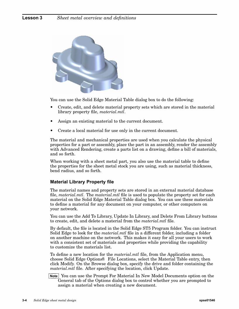
Create a tab
▸ Sketch a 50 mm square in the X-Y plane.
▸ Select the region shown.
spse01546 Solid Edge sheet metal design 3-9

Lesson 3 Sheet metal overview and definitions
▸ Create a tab by selecting the downward pointing vertical handle down. Clickto accept.
Note Notice the material thickness corresponds to the gage set in the previous step.
The tab is created.
▸ Proceed to the next step.
Create flanges from the tab
▸ Select the two thickness faces shown.
3-10 Solid Edge sheet metal design spse01546

Sheet metal overview and definitions
▸ Select the flange start handle
▸ Enter a distance of 50 mm for the new flanges.
spse01546 Solid Edge sheet metal design 3-11

Lesson 3 Sheet metal overview and definitions
Note Two flanges were created from the thickness faces on the tab. Notice the newentries in PathFinder.
▸ Close the sheet metal document without saving. This completes the activity.Proceed to the activity summary.
Activity summary
In this activity you set the material thickness using the gage tab on the materialtable. A tab was placed and flanges were created from the thickness faces of the tab.
Lesson reviewAnswer the following questions:
1. Assign a term from the list below to each number.
3-12 Solid Edge sheet metal design spse01546

Sheet metal overview and definitions
Corner
Bend Relief
Cutouts
Procedural Feature
Tab-Flange
Bend
Plate
2. Name three methods of setting material thickness in a sheet metal document.
Lesson summaryIn this lesson you set the material thickness using the gage tab on the materialtable. A tab was placed and flanges were created from the thickness faces of the tab.
spse01546 Solid Edge sheet metal design 3-13


Lesson
4 Base Features
Base features in sheet metal
A base feature in sheet metal is the first thickness plate placed in a sheet metal file.You can create the base feature by placing a tab, which is a single thickness plate, ora contour flange, which can consist of additional flanges and bends.
Construct the base feature
You can construct a base feature with the Tab, Contour Flange, and Lofted Flange(ordered only) commands. The Tab command constructs a flat feature of any shapeusing a closed profile.
spse01546 Solid Edge sheet metal design 4-1

Lesson 4 Base Features
Ordered
Synchronous
The Contour Flange command (ordered) constructs a feature comprised of one ormore bends and flats using an open profile.
Ordered
The Lofted Flange command (ordered) quickly constructs a flange using two openprofiles on parallel reference planes. Like the Contour Flange command, the LoftedFlange command automatically adds bends using the bend radius property. You donot have to draw an arc at each bend location.
4-2 Solid Edge sheet metal design spse01546

Base Features
Ordered
In ordered, if you want to use a different bend radius value, you can do this bydrawing arcs in the profiles.
Ordered
The Bending Method tab (ordered) on the Lofted Flange dialog box createsincremental bends for all bends in the flange.
Ordered
In ordered, you can set the number of bends. For the lofted flange to flatten, the arcangle must match between the two cross sections.
spse01546 Solid Edge sheet metal design 4-3

Lesson 4 Base Features
Tab commandConstructs a tab feature on a sheet metal part. You can use this command toconstruct a base feature or add a feature to an existing sheet metal part.
In the synchronous environment, you can construct a tab with a single sketch region,
or with multiple sketch regions.
Creating tabs in the ordered environment
In the ordered environment, you can only have one profile per tab feature.
When selecting multiple regions, the regions must be contiguous and in the sameplane. When constructing a base feature in the ordered environment, the profilemust be closed, and you must also define the material direction and materialthickness you want.
4-4 Solid Edge sheet metal design spse01546

Base Features
For subsequent features in the ordered environment, the profile can be open orclosed. When using an open profile, you must define the side of the profile to whichyou want to add material.
Creating tabs in the synchronous environment
When constructing a base feature in the synchronous environment, the sketchregion must be closed, and you must also define the material direction and materialthickness you want.
For subsequent features in the synchronous environment, the sketch can be openor closed. If the sketch is open the edge of the tab must close the sketch to form asketch region. Subsequent features are automatically added when you select theextrude handle.
spse01546 Solid Edge sheet metal design 4-5

Lesson 4 Base Features
Editing tabs
Once you create a tab, you cannot change the thickness or offset direction for thetab. You can use the Material Table to change things such as global thickness, bendrelief, and relief depth.
Construct a tabYou can construct a tab as a base feature or add a tab to an existing sheet metal part.
Construct a tab in the ordered environment
1. Choose Home tab®Sheet Metal group®Tab .
2. Define the profile plane.
3. Draw an open profile in any 2D shape or copy a profile into the profile window.The ends of an open profile are extended to the edges of the part plane. An arcwith open ends is extended to form a circle.
Note If you are using the Tab command to construct a base feature, the profilemust be closed.
4. Choose Home tab®Close group®Close.
5. Finish the feature.
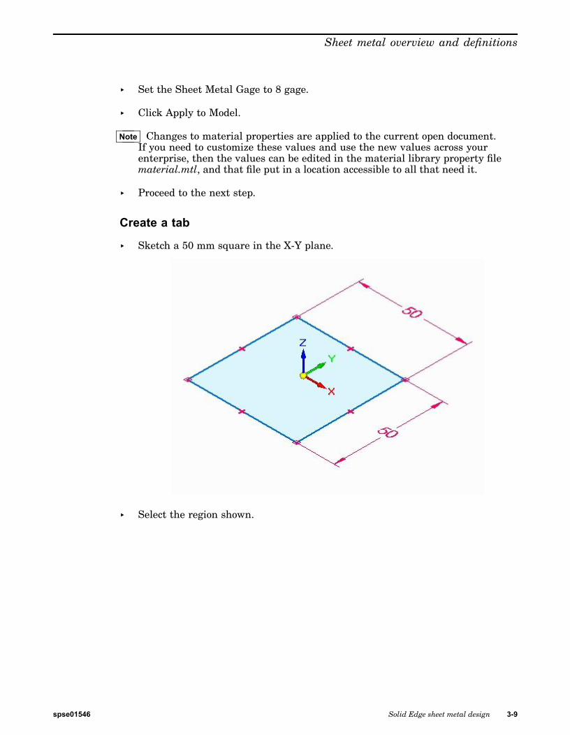
Construct a tab as a base feature in the synchronous environment
1. Position the cursor over a sketch region, then click to select it.
The extrude handle is displayed.
2. Click the Extrude handle.
4-6 Solid Edge sheet metal design spse01546
Base Features
3. Type a thickness value for the part.
4. Right-click to create the tab.
Tip
• You can choose the Material Table button on the command bar to display theSolid Edge Material Table dialog box to make changes to things such asglobal thickness, bend relief, and relief depth.
• You can click the direction indicator handle to change the offset direction.
spse01546 Solid Edge sheet metal design 4-7

Lesson 4 Base Features
Add a tab to an existing sheet metal part in the synchronous environment
1. Position the cursor over a sketch region, then click to select it.
The extrude handle displays.
2. Click the Extrude handle.
4-8 Solid Edge sheet metal design spse01546

Base Features
The tab is automatically added.
Cut commandCreates a cut through a defined portion of a part.
You can create a sheet metal cutout with an open profile
spse01546 Solid Edge sheet metal design 4-9

Lesson 4 Base Features
or a closed profile.
4-10 Solid Edge sheet metal design spse01546

Base Features
Face Normal cut types
Face Normal cut types include:
Thickness cut
This option creates a cutout that compensates for the material thickness ofthe part.
The Thickness cut option is useful when creating parts in which a shaft mustpass through aligned circular cutouts.
Mid–plane cut
This option creates a cutout based on the mid-plane of the part.
Nearest Face cut
This option creates a cutout based on the nearest face of the part.
spse01546 Solid Edge sheet metal design 4-11

Lesson 4 Base Features
Cuts across bends
The Wrapped Cut option unfolds the bend to create a cut,
and then rebends when the cut is complete.
4-12 Solid Edge sheet metal design spse01546

Base Features
Activity: Using regions to create tabs and cuts
Using regions to create tabs and cuts
Activity objectives
This activity demonstrates how to create various tabs in sheet metal and how to useregions to make cuts. In this activity you will:
• Create a tab base feature from a sketch.
• Add additional tabs to the base feature.
• Create flanges.
• Explore the different options available when cutting a sheet metal part.
Open a sheet metal file
▸ Start Solid Edge ST5.
▸ Click the Application button® Open® tab_cut_activity.psm.
Note In this activity, the material thickness has been set to 2.0 mm and the bendradius has been set to 1.0 mm.
Use the sketch to create the base feature
▸ Use the region shown to create the base feature from the sketch geometry. Selectthe handle pointing up.
spse01546 Solid Edge sheet metal design 4-13

Lesson 4 Base Features
▸ Click to place the base feature, a tab, above the sketch as shown. Press Enter toaccept the material thickness of 2.00 mm.
▸ To place the next tab, select the region shown.
4-14 Solid Edge sheet metal design spse01546

Base Features
▸ Select the handle pointing up as shown. Since the material thickness is defined,the tab will be placed when the handle is selected.
The base feature appears as shown.
Create the flanges
▸ Select the edges as shown and click the flange command.
spse01546 Solid Edge sheet metal design 4-15

Lesson 4 Base Features
▸ Pull the flange down a distance of 40.00 mm.
Creating a cut
▸ Lock the sketch plane to the top face and place a rectangle approximately asthe one shown below.
4-16 Solid Edge sheet metal design spse01546

Base Features
▸ Select the two regions shown. Notice the Cut command is selected. Click thedownward pointing handle as shown.
spse01546 Solid Edge sheet metal design 4-17

Lesson 4 Base Features
▸ Click the endpoint on the edge shown to create the cut.
Note Notice the depth of the cut is defined by the vertical distance below theregions.
Creating a wrapped cut
The wrapped cut command temporarily flattens the bend to place the cut.
4-18 Solid Edge sheet metal design spse01546

Base Features
▸ Create an approximate sketch as shown below. Do not extend the sketch morethan 30.00 mm from the edge of the flange.
▸ Select the two regions shown and click the Wrapped Cut option as shown.
spse01546 Solid Edge sheet metal design 4-19

Lesson 4 Base Features
▸ Select the downward pointing handle. The part is unfolded showing a preview ofthe wrapped cut. Right-click to accept.
▸ The results are shown.
▸ Close the sheet metal document without saving.
Moving thickness faces
▸ Click the Application button® Open® tab_move_activity.psm.
4-20 Solid Edge sheet metal design spse01546

Base Features
▸ Select the primary axis of the thickness face shown. The Extend/Trim option isthe default.
▸ Move the primary axis and move in the direction toward the bend. Enter adistance of 5.00 mm.
spse01546 Solid Edge sheet metal design 4-21

Lesson 4 Base Features
▸ Observe the behavior. The length of the thickness face changes and theorientation of the adjacent faces remains constant. The result is as shown below.
▸ Select the primary axis and the Tip option as shown.
4-22 Solid Edge sheet metal design spse01546

Base Features
▸ Enter 11.44 mm for the distance to move the thickness face.
▸ Observe the behavior. The length of the thickness face is constant and theorientation of the adjacent faces changes. The result is as shown below.
spse01546 Solid Edge sheet metal design 4-23

Lesson 4 Base Features
▸ Select the primary axis and the Lift option as shown.
▸ Enter a value of 10.00 mm.
4-24 Solid Edge sheet metal design spse01546

Base Features
▸ Observe the behavior. The length of the thickness face is constant and theorientation of the adjacent faces are constant. The tab extends perpendicularto the thickness face. The result is as shown below.
▸ This completes the activity. Close the sheet metal document without saving.Proceed to the activity summary.
Activity summary
In this activity you created a sheet metal base feature using a tab, and addedadditional material creating a tab from a sketch. Regions were used to create a cutand a wrapped cut. You learned the different options for moving a thickness face.
Lesson reviewAnswer the following questions:
1. Name two commands which can generate a base feature in a sheet metaldocument.
2. Are open cutouts valid in a sheet metal document?
3. What is a wrapped cut in sheet metal?
Lesson summaryIn this lesson you created a sheet metal base feature using a tab, and addedadditional material creating a tab from a sketch. Regions were used to create a cutand a wrapped cut. You learned the different options for moving a thickness face.
spse01546 Solid Edge sheet metal design 4-25

Lesson
5 Contour Flange
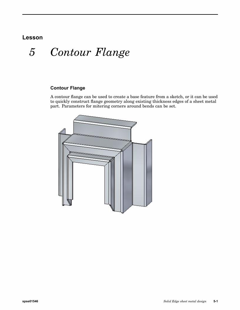
Contour Flange
A contour flange can be used to create a base feature from a sketch, or it can be usedto quickly construct flange geometry along existing thickness edges of a sheet metalpart. Parameters for mitering corners around bends can be set.
spse01546 Solid Edge sheet metal design 5-1

Lesson 5 Contour Flange
Contour Flange commandConstructs a contour flange by extruding a profile that represents the edge of thecontour flange.
Examples: Defining Reference Plane Orientation to Construct aContour Flange
When constructing a contour flange, you must define the orientation of the profileplane relative to an existing edge on the part. Doing this defines both the referenceplane orientation and the path along which the contour flange will be constructed.
For example, suppose you wanted to construct a contour flange as shown in the figure.
You could do this by selecting the endpoint of the edge shown to locate the newreference plane, and then clicking the face shown on the right side of the figure todefine the base of the reference plane.
You could then click near the end shown to define the x axis orientation.
5-2 Solid Edge sheet metal design spse01546

Contour Flange
Activity: Constructing a base feature using contour flange
Constructing a base feature using contour flange
Activity objectives
This activity demonstrates how a contour flange can be used to create a base feature.In this activity you will accomplish the following:
• Create a new sheet metal part.
• Create the material to be used for the part.
• Modify the thickness of the material.
• Create a sketch that will be the basis for the contour flange.
• Examine the PathFinder and understand how a contour flange is defined.
spse01546 Solid Edge sheet metal design 5-3

Lesson 5 Contour Flange
Open a sheet metal file
▸ Click the Application button® Open® contour_actvity_1.psm.
Create a base feature using the Contour Flange command
▸ Click the Contour Flange command.
▸ Select the sketch shown, then click the flange handle.
▸ Click the symmetric extent option.
▸ Use the tab key to change focus between the material thickness field and theextent field. Set the material thickness to be 3.25 mm and the extent to be120.00 mm, and then press the enter key to complete the contour flange.
5-4 Solid Edge sheet metal design spse01546

Contour Flange
▸ The results are shown.
Note The base feature can be created from a contour flange. Tangent curves insketches are used to create bends.
▸ Observe PathFinder by moving the cursor over the features.
Note The tab is created from the element chosen. Connected lines and tangentcurves create flanges.
▸ Save and close the sheet metal document.
Create a contour flange
▸ Click the Application button® Open® contour_actvity_2.psm.
spse01546 Solid Edge sheet metal design 5-5

Lesson 5 Contour Flange
▸ Lock the sketch plane to the plane shown.
▸ Create the sketch shown. All segments are 20.00 mm.
▸ Select the Contour Flange command.
5-6 Solid Edge sheet metal design spse01546

Contour Flange
▸ Select the handle shown.
▸ Continue by selecting the adjacent edge shown.
spse01546 Solid Edge sheet metal design 5-7

Lesson 5 Contour Flange
▸ Continue by selecting the adjacent edge shown.
▸ The preview is shown.
5-8 Solid Edge sheet metal design spse01546

Contour Flange
▸ Right-click to complete the contour flange.
▸ Observe PathFinder by moving the cursor over the features.
Note The contour flange is a single feature. The corner conditions can be edited.
spse01546 Solid Edge sheet metal design 5-9

Lesson 5 Contour Flange
▸ In PathFinder, right-click the contour flange feature, and then click separate.Observe the results.
Note The flange numbers in PathFinder may not match the numbers in theimage above. This is not a problem.
Notice that the contour flange feature was replaced by individual flanges. Asa result, there is no associativity between the flanges, but you can edit theindividual flanges independently of one another.
▸ Save and close the sheet metal document.
Contour flange options
▸ Click the Application button® Open® contour_actvity_3.psm.
▸ Select the Contour Flange command.
5-10 Solid Edge sheet metal design spse01546

Contour Flange
Note In the following steps you will change the options for end conditions on thecontour flange and view the end conditions in the preview without acceptinguntil the last step.
▸ Begin the contour flange shown using the default parameters.
▸ Click the Options button.
spse01546 Solid Edge sheet metal design 5-11

Lesson 5 Contour Flange
▸ On the Miters and Corners tab, set the Miter option for the Start End and FinishEnd. Set each angle to –30o, then click OK. Observe the results.
Note The view has been rotated for clarity.
▸ Click the Options button.
5-12 Solid Edge sheet metal design spse01546

Contour Flange
▸ On the Miters and Corners tab, change the start end and finish end miter anglesfrom a negative value to 30o, then click OK. Observe the results.
▸ Click the Options button.
▸ On the Miters and Corners tab, for both the start end and finish end miteroptions, set the Normal to Source Face option, then click OK. Observe the results.
spse01546 Solid Edge sheet metal design 5-13

Lesson 5 Contour Flange
▸ Click the Options button.
▸ Click the Miters and Corners tab.
▸ On the Miters and Corners tab, for both the start end and finish end miteroptions, set the miter angle to –45o. Then click OK. Observe the results.
▸ Click the Options button.
5-14 Solid Edge sheet metal design spse01546

Contour Flange
▸ On the Miters and Corners tab, in the Interior Corners section, set the CloseCorner option. Set the Treatment option to Circular Cutout and click OK.Observe the result.
▸ Right-click to complete the contour flange. The result is shown.
Create a partial contour flange
▸ Select the Contour Flange command.
spse01546 Solid Edge sheet metal design 5-15

Lesson 5 Contour Flange
▸ Select the sketch as shown.
▸ Click the Partial Contour Flange option.
▸ Position the cursor approximately as shown, then click.
▸ The result is shown.
5-16 Solid Edge sheet metal design spse01546

Contour Flange
Note Partial flanges can be further positioned by moving thickness faces orwith dimensions.
▸ This completes the activity.
Activity summary
In this activity you set the material thickness and extent to create a base featureusing a contour flange. The components of the contour flange were examined andmanipulated. Options for the construction of end conditions were explored, and apartial contour flange was placed.
Lesson reviewAnswer the following questions:
1. How can you make a base feature using the contour flange command?
2. Can a part edge be used to define the extent of a contour flange and if so, can anadjacent edge be used to continue the extent?
3. What does the miter option do when used in the creation of a contour flange?
Lesson summaryIn this lesson you set the material thickness and extent to create a base featureusing a contour flange. The components of the contour flange were examined andmanipulated. Options for the construction of end conditions were explored, and apartial contour flange was placed.
spse01546 Solid Edge sheet metal design 5-17


Lesson
6 Flanges, corners and bend relief
Flanges, corners and bend relief
You create flanges using flange handles. As you create them, you can control endconditions such as bend relief and corner conditions. You can insert bends acrosslayer faces.
spse01546 Solid Edge sheet metal design 6-1
Lesson 6 Flanges, corners and bend relief
Creating flanges
Creating flanges
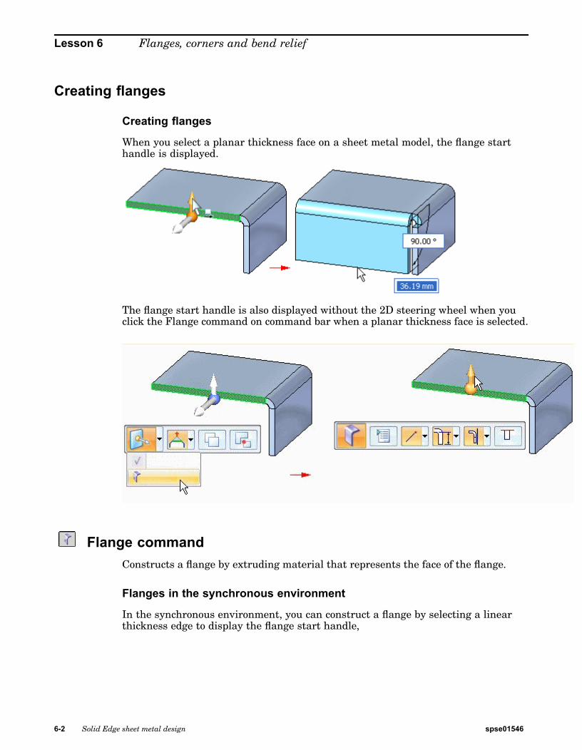
When you select a planar thickness face on a sheet metal model, the flange starthandle is displayed.
The flange start handle is also displayed without the 2D steering wheel when youclick the Flange command on command bar when a planar thickness face is selected.
Flange commandConstructs a flange by extruding material that represents the face of the flange.
Flanges in the synchronous environment
In the synchronous environment, you can construct a flange by selecting a linearthickness edge to display the flange start handle,
6-2 Solid Edge sheet metal design spse01546

Flanges, corners and bend relief
clicking the flange start handle,
specifying a flange distance,
and clicking to place the flange.
When you click, a 90° flange is drawn automatically. However, when specifying thedistance for the flange, you can also specify an angle.
spse01546 Solid Edge sheet metal design 6-3

Lesson 6 Flanges, corners and bend relief
Note Use the Tab button to switch between the distance and angular value controls.
Flanges in the ordered environment
In the ordered environment, you construct a flange by selecting a linear thicknessedge, and then reposition the cursor to define the flange direction and length.
6-4 Solid Edge sheet metal design spse01546

Flanges, corners and bend relief
Corner Relief
Corner Relief
Specifies that you want to apply corner relief to flanges that are adjacent to theflange you are constructing. When you set this option, you can also specify how youwant the corner relief applied.
Bend Only
Specifies that corner relief is only applied to the bend portion of the adjacent flanges.
Bend and Face
Specifies that corner relief is applied to both the bend and face portions of theadjacent flanges.
Bend and Face Chain
Specifies that corner relief is applied to the entire chain of bends and faces of theadjacent flanges.
Bend commandInserts a bend across a planar face. You can use the command to add a bend in themiddle of a part. The bend profile must be a single linear element. You cannotinsert a bend across an existing flange.
spse01546 Solid Edge sheet metal design 6-5

Lesson 6 Flanges, corners and bend relief
Insert a bendIn the ordered environment, you can insert a bend with the Bend command.
In the synchronous environment, you can insert a bend with the Select tool or inserta bend with the Bend command. Both workflows are explained in this topic.
Insert a bend in the ordered environment
1. Choose Home tab®Sheet Metal group®Bends list®Bend.
2. Define the profile plane.
3. Draw a profile. The profile, which must be a single linear element, representsthe approximate location of the bend.
4. Choose Home tab®Close group®Close.
5. Define the bend location with respect to the profile.
6. Define which side of the part will move.
7. Define the bend direction.
8. Finish the feature.
Tip
• You can automatically flatten the bend by setting the Flatten Bend option onthe Bend Options dialog box.
Insert a bend in the synchronous environment with the Select tool
1. Choose Home tab®Select group®Select .
2. Select the sketch element to create the bend.
6-6 Solid Edge sheet metal design spse01546

Flanges, corners and bend relief
3. Choose Home tab®Sheet Metal group®Bends list®Bend .
4. Click the side of the sketch to move.
5. (Optional) Click to the direction arrow to change the direction of the bend.
6. (Optional) Type a value to change the bend angle.
7. Click to create the bend.
spse01546 Solid Edge sheet metal design 6-7

Lesson 6 Flanges, corners and bend relief
Insert a bend in the synchronous environment with the Bend command
1. Choose Home tab®Sheet Metal group®Bends list®Bend .
2. Select the sketch element to create the bend.
3. Click the side of the sketch to move.
4. (Optional) Click to the direction arrow to change the direction of the bend.
5. (Optional) Type a value to change the bend angle.
6-8 Solid Edge sheet metal design spse01546
Flanges, corners and bend relief
6. Click to create the bend.
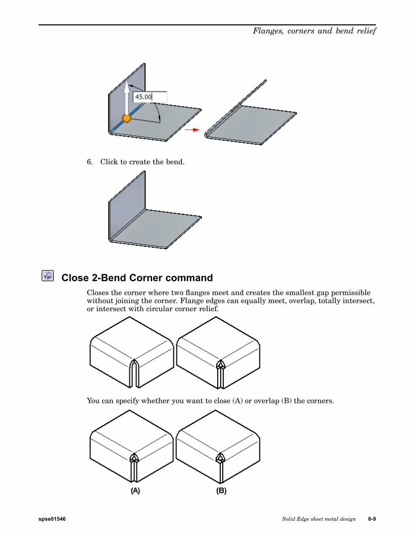
Close 2-Bend Corner commandCloses the corner where two flanges meet and creates the smallest gap permissiblewithout joining the corner. Flange edges can equally meet, overlap, totally intersect,or intersect with circular corner relief.
You can specify whether you want to close (A) or overlap (B) the corners.
spse01546 Solid Edge sheet metal design 6-9

Lesson 6 Flanges, corners and bend relief
You cannot directly move of rotate a bend corner. However, you can move or rotatethe bend corner by repositioning the adjacent flanges that form the corner. If a platethat contributes to the closed corner is deleted, the bend faces created by the closedcorner are deleted and the closed corner definition is removed from the model.
You can select a closed corner for deletion, either in PathFinder or in the graphicswindow. When you delete a closed corner, the corner definition is removed from themodel and bends return to the default bend state.
Activity: Flange and corner conditions
Flange and corner conditions
Activity objectives
This activity demonstrates control flange geometry and end contditions within asheet metal part. In this activity you will:
• Place flanges.
• Place partial flanges.
• Define and edit bend relief for bends.
• Defining corner conditions.
• Inserting a bend across a layer face.
• Rotating faces.
Open a sheet metal file
▸ Start Solid Edge ST5.
6-10 Solid Edge sheet metal design spse01546

Flanges, corners and bend relief
▸ Click the Application button® Open® flange_activity.psm.
Note This sheet metal part has a material thickness of 1.50 mm and a bend radiusof 1.00 mm.
Flange creation options
▸ Select the face shown and click the flange start handle.
▸ Create a flange with the default parameters that has the length of 40.00 mm.
spse01546 Solid Edge sheet metal design 6-11

Lesson 6 Flanges, corners and bend relief
▸ Create the flange shown below with a length of 10.00 mm.
Note The following steps will demonstrate the different options for corner relief.
▸ Select the face shown and click the flange handle. Click flange options andensure the Corner Relief is set to Bend Only.
6-12 Solid Edge sheet metal design spse01546

Flanges, corners and bend relief
▸ Pull the flange to the end of the bottom of the flange just created. Observe thecorner relief.
▸ Click the Undo command to remove the flange you just created.
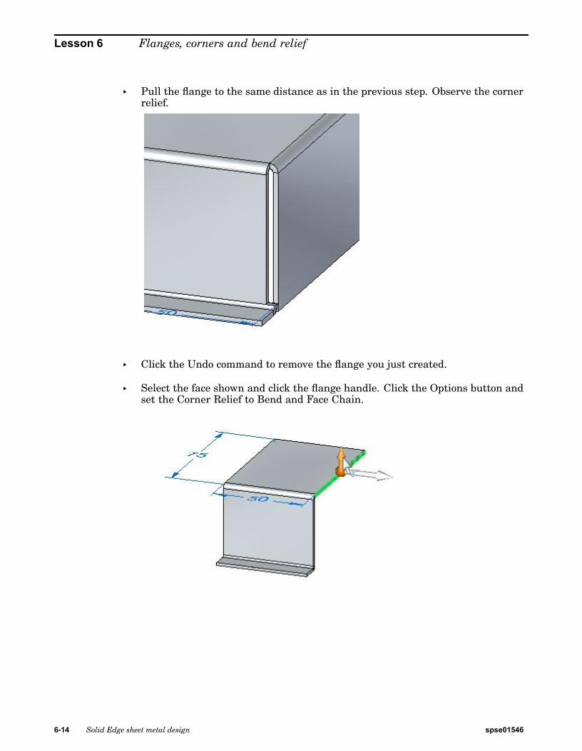
▸ Select the face shown and click the flange handle. Click the Options button andset the Corner Relief to Bend and Face.
spse01546 Solid Edge sheet metal design 6-13
Lesson 6 Flanges, corners and bend relief
▸ Pull the flange to the same distance as in the previous step. Observe the cornerrelief.
▸ Click the Undo command to remove the flange you just created.
▸ Select the face shown and click the flange handle. Click the Options button andset the Corner Relief to Bend and Face Chain.
6-14 Solid Edge sheet metal design spse01546

Flanges, corners and bend relief
▸ Pull the flange to the same distance as in the previous step. Observe the cornerrelief.
▸ Close the file without saving.
Partial flanges
▸ Click the Application button® Open® relief_activity.psm.
Note This sheet metal part has a material thickness of 1.50 mm and a bend radiusof 1.00 mm.
▸ Select the face shown and select the flange start handle.
spse01546 Solid Edge sheet metal design 6-15

Lesson 6 Flanges, corners and bend relief
▸ Click the Partial Flange option and create a flange with a length of 30.00 mm.
Note Partial flanges are created with a width equal to 1/3 of the thickness facechosen, and the selection point is defines the edge of the partial flange. Theflange can be modified to the desired width using dimensions to control thewidth.
▸ Click the smart dimension command.
▸ Place a dimension on the bottom edge of the flange just created. Change thewidth of the flange to 15.00 mm by editing the dimension.
6-16 Solid Edge sheet metal design spse01546

Flanges, corners and bend relief
▸ Select the face shown.
▸ The origin of the start point will be changed by moving the steering wheel to theend of the thickness face. Move the steering wheel to the position shown, andselect the flange command from the command bar.
spse01546 Solid Edge sheet metal design 6-17

Lesson 6 Flanges, corners and bend relief
▸ Click the partial flange option and create a flange with a length of 30.00 mm.
Note The origin of this flange partial flange is at the end of the thickness faceand is 1/3 the length of the thickness face.
Bend relief
Note The default bend relief can be overridden during placement, or after placementwhen editing a bend.
▸ Select the bend shown, then click the edit feature handle.
6-18 Solid Edge sheet metal design spse01546

Flanges, corners and bend relief
▸ Click the Bend Options button.
▸ Select the Override Global Value next to the Depth field and change the depth to3.00 mm. Repeat the step to change the width to 2.00 mm.
▸ Experiment with different lengths, widths, and types of bend relief beforedismissing the bend options dialog box and observe the results.
▸ Close the sheet metal document without saving.
spse01546 Solid Edge sheet metal design 6-19

Lesson 6 Flanges, corners and bend relief
Corners
▸ Click the Application button® Open® corner_activity.psm.
Note This sheet metal part has a material thickness of 1.50 mm and a bend radiusof 1.00 mm.
▸ Select the region shown and create a tab by pulling the handle up.
▸ Select all thickness faces and then click the flange start handle.
6-20 Solid Edge sheet metal design spse01546
Flanges, corners and bend relief
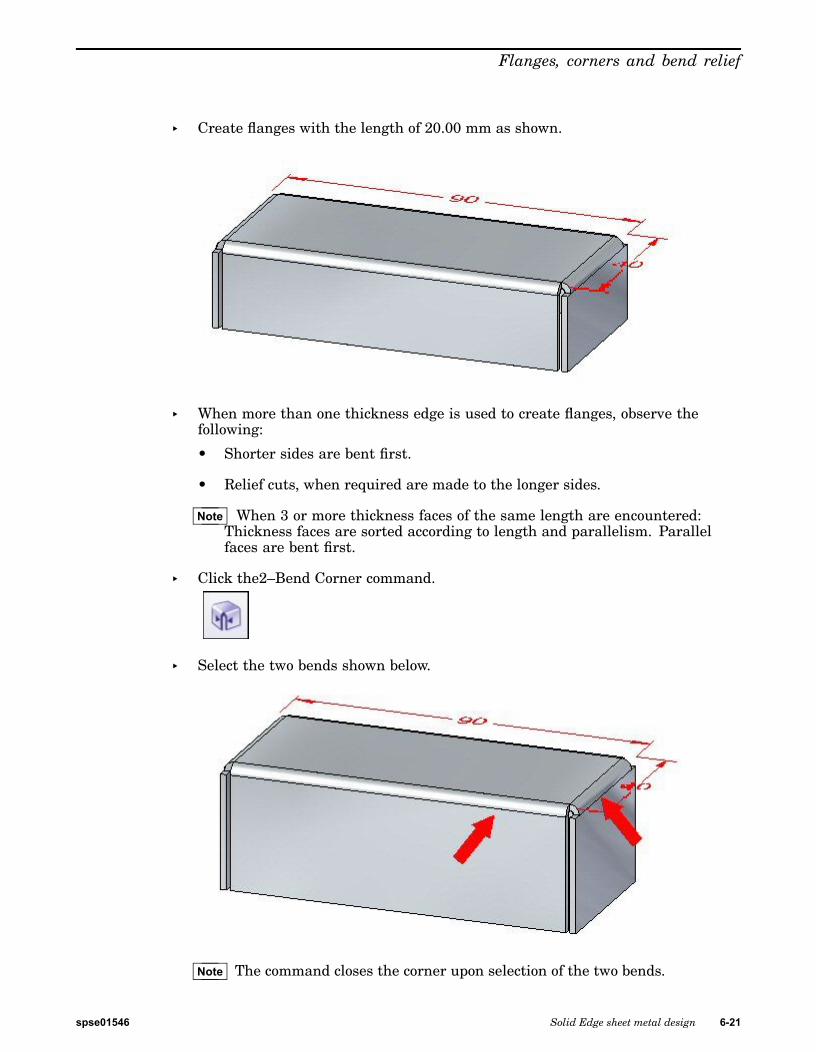
▸ Create flanges with the length of 20.00 mm as shown.
▸ When more than one thickness edge is used to create flanges, observe thefollowing:
• Shorter sides are bent first.
• Relief cuts, when required are made to the longer sides.
Note When 3 or more thickness faces of the same length are encountered:Thickness faces are sorted according to length and parallelism. Parallelfaces are bent first.
▸ Click the2–Bend Corner command.
▸ Select the two bends shown below.
Note The command closes the corner upon selection of the two bends.
spse01546 Solid Edge sheet metal design 6-21

Lesson 6 Flanges, corners and bend relief
▸ Click the Overlapping Corner option with the Corner Treatment set to Open.
▸ Change the gap value to 0.30 mm and the overlap ratio to 0.75. Observe theresults.
▸ Click the Flip option and observe the results.
▸ Click the Closed Corner option. Observe the how the corner closes.
▸ Change the Corner Treatment to Closed, and set the gap value to 0.30 mm.Observe the change.
▸ Change the Corner Treatment to Circular Cutout, and set the gap value to 0.40mm. Set the diameter to 1.50 mm. Observe the change.
▸ Close the sheet metal document without saving.
Inserting a bend
▸ Click the Application button® Open® bend_activity.psm.
▸ Select the region shown and create a cutout.
6-22 Solid Edge sheet metal design spse01546

Flanges, corners and bend relief
▸ Sketch a line as shown across the tab.
▸ Click the Bend command.
▸ Select the line as shown.
spse01546 Solid Edge sheet metal design 6-23

Lesson 6 Flanges, corners and bend relief
▸ Select the Material Outside option.
▸ Select the side shown. Notice the extent of the bend traverses the length ofthe layer face.
▸ Click the Bend Options button.
6-24 Solid Edge sheet metal design spse01546

Flanges, corners and bend relief
▸ Deselect Extend Profile and click OK.
▸ Right-click to complete the bend and add the flange. The results are shown.
spse01546 Solid Edge sheet metal design 6-25

Lesson 6 Flanges, corners and bend relief
Editing a bend
▸ Click the Select tool and select the bend. Click the edit handle as shown.
▸ Click the Options button and set the relief to be round with a width of 5.00mm and a depth of 5.00 mm.
Note The relief could have been set during the creation of the bend in theprevious step. The purpose of changing the relief at this point is todemonstrate the ability to edit a previously placed feature.
6-26 Solid Edge sheet metal design spse01546
Flanges, corners and bend relief
▸ Sketch a line as shown across the tab.
▸ Click the Bend command.
▸ Select the line as shown.
▸ Select the Material Inside option.
spse01546 Solid Edge sheet metal design 6-27

Lesson 6 Flanges, corners and bend relief
▸ Right-click to complete the bend.
▸ Rotate the view and examine the two bends just placed. The flat pattern isshown.
Note The two bends placed used the length of existing material to create the flanges.Compare this workflow to the jog command in another activity.
Note Creating a flat pattern will be covered in another activity.
▸ Close the file without saving.
Moving faces
▸ Click the Application button® Open® move_activity.psm.
6-28 Solid Edge sheet metal design spse01546

Flanges, corners and bend relief
▸ Select the face shown.
▸ Select the origin of the steering wheel and position the steering wheel as shown.
spse01546 Solid Edge sheet metal design 6-29

Lesson 6 Flanges, corners and bend relief
▸ Select the steering wheel torus and rotate the flange by an angle of 25o as shown.
Note The lower horizontal flange is shortened as the face is moved. Thehorizontal flange can be made to made to maintain the 90o bend angle byadjusting live rules and adding the components of the flange to the selection.
▸ Click the 2–Bend corner command.
6-30 Solid Edge sheet metal design spse01546

Flanges, corners and bend relief
▸ Select the two bends shown.
The corner is closed.
spse01546 Solid Edge sheet metal design 6-31

Lesson 6 Flanges, corners and bend relief
▸ Select the face shown.
▸ Ensure that the Maintain Thickness Chain option in Live Rules is no selected.
▸ Select the steering wheel torus and rotate the flange by an angle of –35o asshown.
6-32 Solid Edge sheet metal design spse01546
Flanges, corners and bend relief
Note The closed corner remains closed and modifies both flanges associatedwith the corner.
▸ Close the sheet metal document without saving.
Activity summary
In this activity you placed flanges and partial flanges. You edited end and cornertreatments for bends. You used the closed the corners of adjacent thickness facesat the intersection of two bends. Bends were placed on the layer face and flangeswere created and edited from these bends.
Lesson reviewAnswer the following questions:
1. What is the purpose of bend relief in a sheet metal part?
2. How do you insert a synchronous bend into a sheet metal part?
3. How can you use the steering wheel to change the angle of a bend?
4. Can change and customize the values of the bend formula?
5. List three types of corner relief and describe each type.
Lesson summaryIn this lesson you placed flanges and partial flanges. You edited end and cornertreatments for bends. You used the closed the corners of adjacent thickness facesat the intersection of two bends. Bends were placed on the layer face and flangeswere created and edited from these bends.
spse01546 Solid Edge sheet metal design 6-33


Lesson
7 Hem
Constructing a hem in a sheet metal part
A hem feature creates a rigid edge for a sheet metal part. Modeling hems can be aseasy as selecting the edges where you want to place them.
Hem commandConstructs a hem, where the material folds back.
In the synchronous environment, you can construct a hem along a linear edge.
In the ordered environment, you can construct a hem along any edge on a sheetmetal part. For example, you can construct a hem along a liner edge
spse01546 Solid Edge sheet metal design 7-1

Lesson 7 Hem
or, along the curved edge of a circular cutout.
Note Bends created with the command are included in bend table.
You can use the Hem Options dialog box to specify the type of hem to be created. TheHem Type list contains several types of hems from which to choose. For example,you can define s-flange (A), loop (B), and closed (C) hems.
You can use the Hem Options dialog box to specify the type of hem to be created. TheHem Type list contains several types of hems from which to choose.
Construct a hem
1. Choose Home tab®Sheet Metal group®Contour Flange list®Hem .
2. Select the edge(s) for the hem.
3. Click to complete the hem.
Tip
• You can use the Hem Options dialog box to specify the type of hem to becreated, along with bend radius, and flange length for the hem. The optionsthat are available depend on the type of hem being created.
7-2 Solid Edge sheet metal design spse01546

Hem
Activity: Using the hem command in sheet metal design
Using the hem command in sheet metal design
Activity objectives
This activity demonstrates how to create a hem on the edge of a sheet metal part.In this activity you will:
• Create a simple hem on a single edge of a sheet metal part.
• Vary the options for creating hems.
• Control the extent and end treatments of hems placed along adjacent thicknessfaces.
Open a sheet metal file
▸ Start Solid Edge ST5.
▸ Click the Application button® Open® hem_activity_1.psm.
Create a hem on a single edge
▸ Click the Hem command .
▸ Click the Hem Options button .
▸ Set the Hem Type to be Closed and Flange Length 1 to be 15.00 mm.
spse01546 Solid Edge sheet metal design 7-3

Lesson 7 Hem
▸ Select the edge shown.
▸ Right-click to complete the hem shown.
▸ Click the Select tool and then click the hem feature in PathFinder. Click the edithandle to change the settings on the hem.
7-4 Solid Edge sheet metal design spse01546

Hem
▸ Click the Hem Options button and set the Type to Open. Set Bend Radius 1to 1.50 mm. Set Flange Length 1 to 6.00 mm and then click OK. The hemis modified as shown.
▸ Click the Hem Options button and set the Type to S-Flange. Keep the defaultvalues for bend radii and flange lengths, then click OK. The hem is modifiedas shown.
spse01546 Solid Edge sheet metal design 7-5

Lesson 7 Hem
▸ Click the Hem Options button and set the Type to Curl. Set Flange Length 1 to11.25 mm and keep the existing values for the remaining lengths and radii, thenclick OK. The hem is modified as shown.
▸ Click the Hem Options button and set the Type to Closed Loop. Keep the defaultvalues for bend radii and flange lengths, then click OK. The hem is modifiedas shown.
▸ Close the file without saving.
Create a hem on multiple adjacent edges
▸ Click the Application button® Open® hem_activity_2.psm.
▸ Click the Hem command .
▸ Click the Hem Options button .
▸ Set Type to S-Flange.
▸ Check the Miter Hem option and ensure the Miter Angle is –45o.
7-6 Solid Edge sheet metal design spse01546

Hem
▸ Select the edge shown.
▸ Select the edge set shown.
Note Since the selection type is set to chain, the edge set is defined by theperimeter of the part. If a single edge is desired, the selection type can be setto single rather than chain.
▸ Right-click to accept the hem.
spse01546 Solid Edge sheet metal design 7-7

Lesson 7 Hem
▸ Shown below is a flat pattern of the sheet metal part is shown below.
Note Flat pattern creation is covered in another activity. This is for informationpurposes only.
Activity summary
In this activity you created a variety of hems in sheet metal parts. You learned howto set the parameters to create the hems, and how to edit the values when needed.
Lesson reviewAnswer the following questions:
1. Using hem options, define the three types of hems that can be created.
2. What is the difference between using a positive value versus a negative value indefining a hem mitre?
3. When creating a sheet metal hem feature, list at least three options neededto create the hem.
Lesson summaryIn this lesson you created a variety of hems in sheet metal parts. You learned how toset the parameters to create the hems, and how to edit the values when needed.
7-8 Solid Edge sheet metal design spse01546

Lesson
8 Using live rules in sheet metal
Live rules in sheet metal
When you use the steering wheel to modify a portion of a model, Live Rules andrelationships control how the rest of the model responds.
Working with Live RulesUse the Live Rules options to locate and display the inferred geometric relationshipsbetween faces in the current select set and the rest of the model. Use this informationto control how synchronous modifications are performed.
For example, when moving a planar face, use Live Rules to locate and display allthe faces in the model that are coplanar to the face you are moving. Then use LiveRules to specify whether any, some, or all of these coplanar faces are moved whenthe selected face moves.
Live Rules is available for the following types of synchronous modeling modifications:
• Moving or rotating model faces or features in a synchronous part or assemblydocument.
spse01546 Solid Edge sheet metal design 8-1

Lesson 8 Using live rules in sheet metal
• Defining 3D geometric relationships between model faces using the Face Relatecommand in a synchronous part document.
• Editing the value of a 3D dimension in a synchronous part or assembly document.
• Editing the dimensional value of a locked 3D dimension using the Variable Table.
Note Live Rules are not used when editing hole and round features using the EditDefinition handle.
Live Rules options
Live Rules automatically appears when moving faces, defining 3D relationships, orediting dimensions. The active options in Live Rules determine how the rest of themodel reacts to the edit you are performing.
For example, when moving a single planar face with the steering wheel (1), you canuse Live Rules to specify whether other coplanar faces, which are not in the selectset, stay coplanar during the move operation.
In this example, when the Coplanar option in Live Rules is on, the deselectedcoplanar faces stay coplanar (2) when moving the selected face. When the Coplanaroption in Live Rules is off, the deselected coplanar faces remain stationary (3) whenmoving the selected face.
8-2 Solid Edge sheet metal design spse01546

Using live rules in sheet metal
Relationship detection indicators in Live Rules
Detected and active
When Live Rules detects model geometry that matches an active setting (1) inLive Rules, the setting display in Live Rules appears in green (2).
spse01546 Solid Edge sheet metal design 8-3

Lesson 8 Using live rules in sheet metal
Detected and inactive
When Live Rules detects model geometry that matches an inactive setting (1) inLive Rules, the setting display in Live Rules appears in red (2).
Restore Live Rules
The Live Rules options you select or clear for the current edit operation aremaintained for future edit operations in the current design session. When you exitSolid Edge, the Live Rules settings return to the default settings.
You can click the Restore Defaults button to restore the default Live Rulesoptions.
Suspend relationships
You can also Suspend relationships detected for the current edit operation.
Suspend options for relationship categories are on the Live Rules panel. Whenmaking a synchronous edit, the solution honors on these options. You can suspend:
• (1) Live Rule relationships.
• (2) Locked dimensions.
• (3) Persisted relationships.
8-4 Solid Edge sheet metal design spse01546

Using live rules in sheet metal
When you suspend a relationship category, the button changes as shown.
Live Rules in sheet metal modeling
Live Rules works the same in synchronous sheet metal modeling as it does insynchronous part modeling. An additional Live Rules option is available in thesynchronous sheet metal modeling environment. The option is called MaintainThickness Chain.
The Maintain Thickness Chain option maintains the position of a thicknesschain, made up of thickness faces connected by bends, during a move operation.When the Thickness Chain option is set, if you move one thickness face, the otherconnected faces move also.
When the Thickness Chain option is not set, only the selected face or faces move.
Selecting the Suspend Live Rules option does not affect the setting of the ThicknessChain option. In other words, if the Thickness Chain option is set and you select theSuspend Live Rules option, the Thickness Chain options remains set.
The Thickness Chain option ignores the Coplanar rule within the thickness chain sothe thickness chain does not have to be coplanar to work.
spse01546 Solid Edge sheet metal design 8-5

Lesson 8 Using live rules in sheet metal
Relationships are not detected between members of the same thickness chain, butare detected between members of separate chains. So even though the Coplanarrule is not detected within one thickness chain, it is detected from one thicknesschain to another. In the following example, Symmetry and Thickness Chain aredisabled. When the selected face is moved, the faces in red move also because theyare coplanar and are part of a separate thickness chain. Since Thickness Chain isdisabled and the Coplanar rule is not detected within the thickness chain containingthe face selected to move, the blue face does not move.
You may need to set the Orthogonal to Base if Possible option if you want to move orrotate a face that will cause a plate or thickness face to tip at an angle not orthogonalto the base reference plane.
Thickness chain
Thickness chain on a sheet metal part
A contiguous series of thickness faces (A) and bend end caps (B) in a sheet metal part.
8-6 Solid Edge sheet metal design spse01546

Using live rules in sheet metal
Copying, pasting, and attaching sheet metal featuresMany times, you may find it useful to copy and paste an existing sheet metal featurerather than create a new feature.
Once you have pasted the feature, you can use the Attach command to attach thefeature to the face.
spse01546 Solid Edge sheet metal design 8-7

Lesson 8 Using live rules in sheet metal
Copying sheet metal features
You can copy for pasting or attaching:
• flanges, along with the associated bend
• procedural features
• sketches
You cannot copy for pasting or attaching:
• bends
• complex contour flanges
• hems
• dimensions
• closed corners
• gussets, unless the associated bend and flange are selected
When you copy a sheet metal element, the following is copied to the clipboard:
• steering wheel location
• attributes
• profile
• feature origin for procedural features
You can copy and paste multiple elements at once.
8-8 Solid Edge sheet metal design spse01546
Using live rules in sheet metal
Copying elements in feature libraries
You can add eligible sheet metal features to a feature library for copy and paste. Youcan copy sketches between Synchronous Sheet Metal and Synchronous Part whencreating feature libraries. However, the feature library cannot be a mixture of files.In other words, you cannot drag a Synchronous Part document from a feature libraryinto a Synchronous Sheet Metal document.
Pasting and attaching sheet metal features
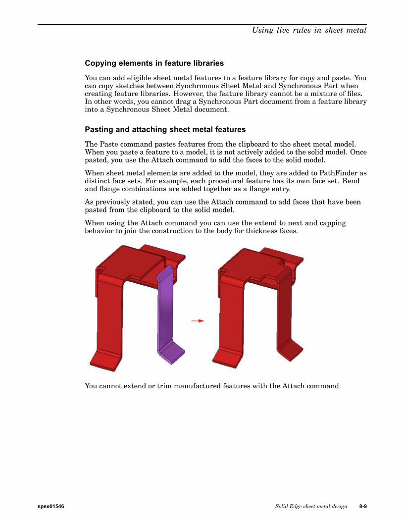
The Paste command pastes features from the clipboard to the sheet metal model.When you paste a feature to a model, it is not actively added to the solid model. Oncepasted, you use the Attach command to add the faces to the solid model.
When sheet metal elements are added to the model, they are added to PathFinder asdistinct face sets. For example, each procedural feature has its own face set. Bendand flange combinations are added together as a flange entry.
As previously stated, you can use the Attach command to add faces that have beenpasted from the clipboard to the solid model.
When using the Attach command you can use the extend to next and cappingbehavior to join the construction to the body for thickness faces.
You cannot extend or trim manufactured features with the Attach command.
spse01546 Solid Edge sheet metal design 8-9

Lesson 8 Using live rules in sheet metal
Copying, pasting, and attaching flanges
When you select a face of a flange to copy, all other faces in the flange are selectedfor copy.
Once you copy the flange and then select the Paste command, a glass image of theflange attaches to the steering wheel.
8-10 Solid Edge sheet metal design spse01546
Using live rules in sheet metal
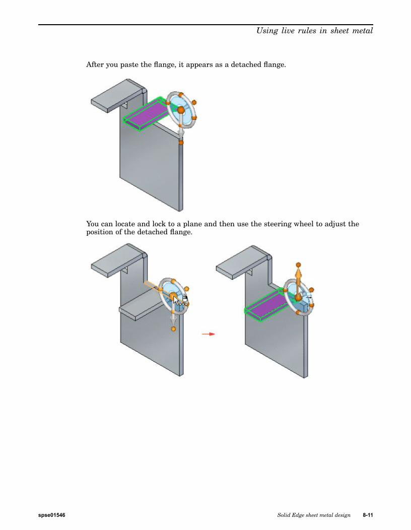
After you paste the flange, it appears as a detached flange.
You can locate and lock to a plane and then use the steering wheel to adjust theposition of the detached flange.
spse01546 Solid Edge sheet metal design 8-11

Lesson 8 Using live rules in sheet metal
Once the position of the flange is valid so that it can be attached, you can use theAttach command to attach the flange to the main body of the model.
When the flange is attached to the main body, all other required faces areautomatically created.
8-12 Solid Edge sheet metal design spse01546

Using live rules in sheet metal
Note When pasting a flange, the open side of the bend (A) must face and be tangentto the target plate (B).
The flange bend can also be embedded into the boundary of the plate.
Activity: Using live rules in sheet metal
Using live rules in sheet metal
Activity objectives
This activity demonstrates how to control behavior when modifying sheet metalparts. In this activity you will:
• Explore Live rules.
• Establish relationships to control behavior of faces.
• Mirror, copy, cut and paste sheet metal features.
spse01546 Solid Edge sheet metal design 8-13

Lesson 8 Using live rules in sheet metal
Open a sheet metal file
▸ Start Solid Edge ST5.
▸ Click the Application button® Open® live_rules_activity.psm.
8-14 Solid Edge sheet metal design spse01546

Using live rules in sheet metal
Symmetry about the base reference planes
Note In this activity, behavior of the live rules can be observed by watching thedynamic preview while pulling one of the handles. In many cases, just observingthe behavior without actually making the change is what will be accomplished.Pressing the Esc key will exit a the command without making any modifications.If a flange is moved erroneously, use the undo command to restore it’s position.
▸ Select the face shown and click the primary axis.
▸ Click the Live Rules Restore button.
Note This resets the live rules to the default values.
spse01546 Solid Edge sheet metal design 8-15

Lesson 8 Using live rules in sheet metal
▸ Drag the handle as shown and observe the behavior, then press the Esc key.
Observations:
• The flange chosen is symmetrical to the opposite flange about the right YZbase reference plane. The live rule for symmetry is controlling the behaviorof the opposite flange.
▸ Select the face shown and click the primary axis.
▸ In Live Rules, turn off symmetry about the YZ base reference plane.
8-16 Solid Edge sheet metal design spse01546

Using live rules in sheet metal
▸ Drag the handle as shown and observe the behavior, then press the Esc key.
Observations:
• The live rule controlling symmetry about the YZ plane is turned off and themoving the thickness face causes the flange to be modified independently.
Creating persistent rules
A permanent relationship between two faces will be created.
▸ Select the two faces shown and click the flange start handle.
▸ Click the Live Rules Restore button.
Note This resets the live rules to the default values.
spse01546 Solid Edge sheet metal design 8-17

Lesson 8 Using live rules in sheet metal
▸ Drag the flange start handle a distance of 40.00 mm as shown.
▸ Select the face shown.
8-18 Solid Edge sheet metal design spse01546
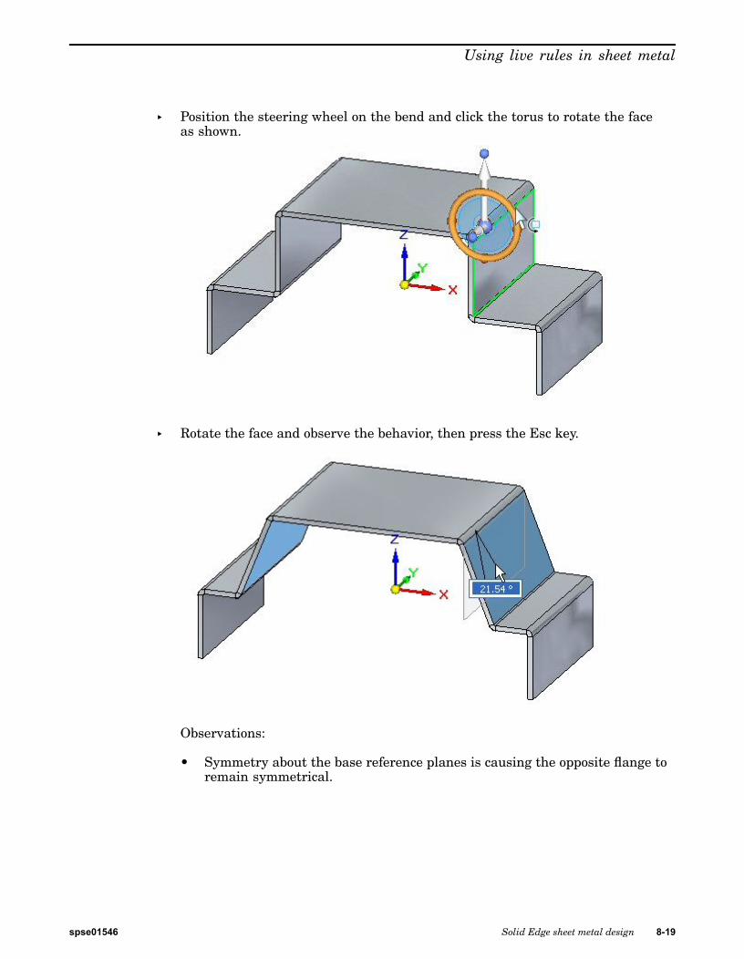
Using live rules in sheet metal
▸ Position the steering wheel on the bend and click the torus to rotate the faceas shown.
▸ Rotate the face and observe the behavior, then press the Esc key.
Observations:
• Symmetry about the base reference planes is causing the opposite flange toremain symmetrical.
spse01546 Solid Edge sheet metal design 8-19

Lesson 8 Using live rules in sheet metal
▸ Select the face shown.
▸ Click the Face Relate->Parallel command.
▸ On the command bar select the Persist option. Select the face shown.
▸ Click the green check to accept.
8-20 Solid Edge sheet metal design spse01546

Using live rules in sheet metal
Note A persistent relationship making the two faces parallel has beenestablished and is displayed in PathFinder.
▸ Select the face shown.
▸ Position the steering wheel on the bend and click the torus to rotate the faceas shown.
spse01546 Solid Edge sheet metal design 8-21

Lesson 8 Using live rules in sheet metal
▸ Rotate the face and observe the behavior.
▸ Rotate the face 20o.
Observations:
• Symmetry about the base reference planes is causing the opposite flangesto remain symmetrical. The vertical flanges remain parallel due to thepersistent relationship established previously.
Thickness Chain
Thickness chain is a live rule unique to sheet metal.
8-22 Solid Edge sheet metal design spse01546

Using live rules in sheet metal
▸ Select the thickness face shown and select the move handle.
▸ Click the Live Rules Restore button.
Note This resets the live rules to the default values.
spse01546 Solid Edge sheet metal design 8-23

Lesson 8 Using live rules in sheet metal
▸ Drag the handle as shown and observe the behavior, then press the Esc key.
Observations:
• The live rules affecting the behavior are thickness chain, maintain coplanarfaces and symmetry about the base reference planes.
▸ Select the thickness face shown and select the move handle.
▸ Turn off symmetry in Live Rules.
8-24 Solid Edge sheet metal design spse01546

Using live rules in sheet metal
▸ Drag the handle as shown and observe the behavior, then press the Esc key.
Observations:
• The live rules affecting the behavior are thickness chain, and maintaincoplanar faces.
▸ Select the thickness face shown and select the move handle.
▸ Turn off Maintain Coplanar Faces in Live Rules.
spse01546 Solid Edge sheet metal design 8-25

Lesson 8 Using live rules in sheet metal
▸ Drag the handle as shown and observe the behavior, then press the Esc key.
Observations:
• When a face is selected and it is part of a thickness chain, the maintaincoplanar faces for that thickness chain is overridden. This will becomeapparent in the next step.
▸ Select the thickness face shown and select the move handle.
▸ Turn on Maintain Coplanar Faces, and turn off Thickness Chain in Live Rules.
8-26 Solid Edge sheet metal design spse01546

Using live rules in sheet metal
▸ Drag the handle as shown and observe the behavior, then press the Esc key.
Observations:
• Even though Maintain Coplanar Faces is turned on, because ThicknessChain is off, only the face selected is moved.
▸ Create the cutout approximately as shown.
spse01546 Solid Edge sheet metal design 8-27

Lesson 8 Using live rules in sheet metal
▸ Select the thickness face shown and select the move handle.
▸ Turn on Maintain Coplanar Faces, and turn off thickness Chain in Live Rules.
▸ Drag the handle as shown and observe the behavior, then press the Esc key.
8-28 Solid Edge sheet metal design spse01546

Using live rules in sheet metal
Observations:
• Even though Maintain Coplanar Faces is turned on, because the thicknesschain is off, only the face selected is moved. Maintain coplanar faces doesnot apply to faces residing in a thickness chain.
Note Thickness chain can also consist of non planar thickness faces connectedby bends as shown in the example below. The arrow points to a face,created by a jog, which is not coplanar to the other thickness faces.
Activity summary
In this activity you explored the behavior of sheet metal geometry by creatingrelationships and changing live rules.
Lesson reviewAnswer the following questions:
1. Define sheet metal thickness chain.
2. Describe how the maintain thickness chain option affects the movement of aface contained in the thickness chain.
3. Describe how live rules affects faces of the same thickness chain as opposed toanother thickness chain.
spse01546 Solid Edge sheet metal design 8-29

Lesson 8 Using live rules in sheet metal
Lesson summaryIn this lesson you explored the behavior of sheet metal geometry by creatingrelationships and changing live rules.
8-30 Solid Edge sheet metal design spse01546

Lesson
9 Jog
Constructing a Jog in a sheet metal part
A jog constructs an offset face with a connecting flange and maintains the positionsof any features contained on the face, such as holes and deformation features.
Jog commandConstructs two bends to add a jog to a planar face of a sheet metal part. In theordered environment, the profile for a jog feature must be a single linear element. Inthe synchronous environment, the sketch element used to construct the jog must bea single line that is coplanar with the face being bent. The jog can be minimal: forexample, a slight offset or step to provide clearance or rigidity to a part.
spse01546 Solid Edge sheet metal design 9-1
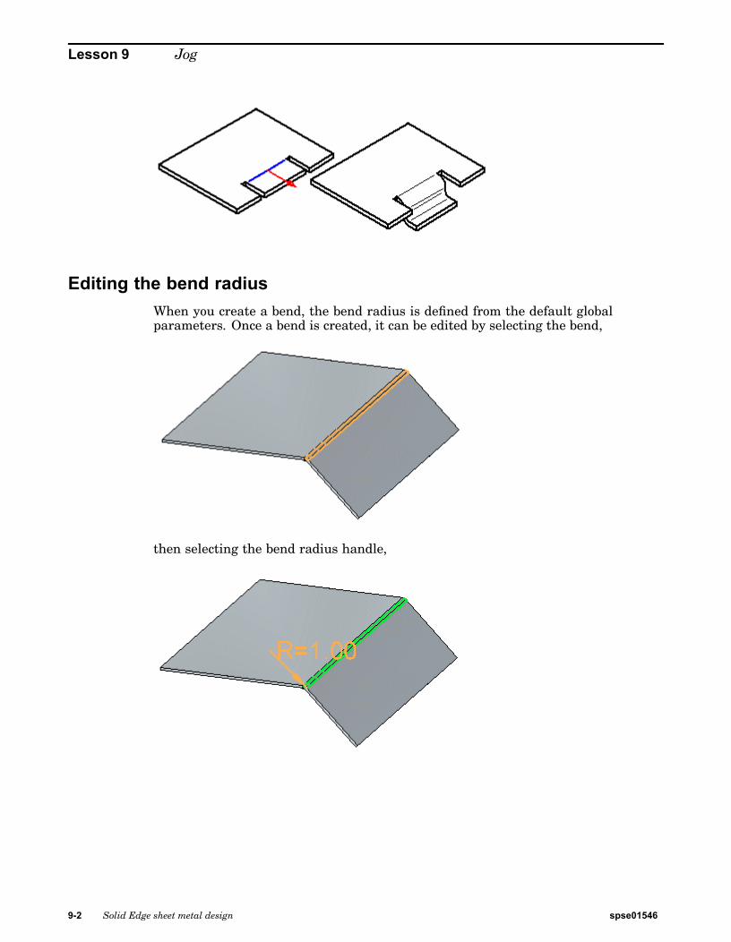
Lesson 9 Jog
Editing the bend radiusWhen you create a bend, the bend radius is defined from the default globalparameters. Once a bend is created, it can be edited by selecting the bend,
then selecting the bend radius handle,
9-2 Solid Edge sheet metal design spse01546

Jog
then typing a new value in the dynamic edit control,
and then clicking to finalize editing the radius.
If you increase the bend radius, bend relief is applied to the model and the bendextends into the flange.
If you decrease the bend radius, the tab and flange extend into the bend to decreasethe bend radius.
spse01546 Solid Edge sheet metal design 9-3

Lesson 9 Jog
Editing the bend radius in split bends
Depending on how split bends are created, the bend radius for split bends may beedited separately or together. If the split bends are created when two flanges arecreated independently as partial flanges, the bend radius can be edited separately.
If the split bends were originally a single bend in a flange, and then cut to make twoseparate flanges,
9-4 Solid Edge sheet metal design spse01546

Jog
the bend radius is edited together.
If the flanges on both sides of the bend are bound by the model, the bend radius foreach bend row is edited together. For example, if you edit the radius for the top bend,the radius is updated for the top bend in both flanges.
spse01546 Solid Edge sheet metal design 9-5

Lesson 9 Jog
Activity: Using the jog and break corner command in sheet metaldesign
Using the jog and break corner command in sheet metal design
Activity objectives
This activity demonstrates how to create a jog in a sheet metal tab, and place flangesand trim away unwanted material from the part. In this activity you will:
• Create a tab based on reference geometry.
• Create the sketches needed by the jog command.
• Set the parameters for the jog.
• Modify the bend radius when and where appropriate.
• Use the break corner command to get rid of sharp corners.
Open a sheet metal file
▸ Start Solid Edge ST5.
▸ Click the Application button® Open® jog_activity.psm.
Note This sheet metal file was created in the context of an assembly. Aninterpart-copy contains geometry from a part file that will be used to define the
9-6 Solid Edge sheet metal design spse01546

Jog
extents of the sheet metal part being created. The geometry has rounded edgeswith a 2.0 mm radius. Knowing this, the proper bend radius can be established.
Draw the sketch and create the base feature
Note This sheet metal file was created in the context of an assembly and inter-partgeometry from a part file was imported into the file. This geometry will be usedto define the extents of the sheet metal that will cover the part. It is visible inPathFinder and the display of the geometry can be toggled on or off there.
▸ Select the Project to Sketch command .
▸ Lock the sketch plane to the top most face on the part.
▸ Use the command to include the following geometry in the sketch:
spse01546 Solid Edge sheet metal design 9-7

Lesson 9 Jog
• The outer edges around the base. Only the straight edges need to be included.
• The 5 holes.
The sketch appears as shown.
9-8 Solid Edge sheet metal design spse01546

Jog
▸ Click the Trim Corner command and trim the outer lines so that theyintersect and form a closed region.
The sketch appears as shown.
▸ Select the region shown.
spse01546 Solid Edge sheet metal design 9-9

Lesson 9 Jog
▸ Click the top arrow to create the base feature above the part geometry as shown.
Create a jog
▸ Click the Jog command and select the line shown.
9-10 Solid Edge sheet metal design spse01546

Jog
▸ Select the direction arrow as shown.
▸ Select the Material Outside option on command bar.
spse01546 Solid Edge sheet metal design 9-11

Lesson 9 Jog
▸ Select the Dimension to Die option on command bar.
▸ Drag the jog down by clicking on a keypoint on the lower face of the part.
The jog is created.
Modifying the bend radius
▸ Observe the following about the jog just created:
9-12 Solid Edge sheet metal design spse01546
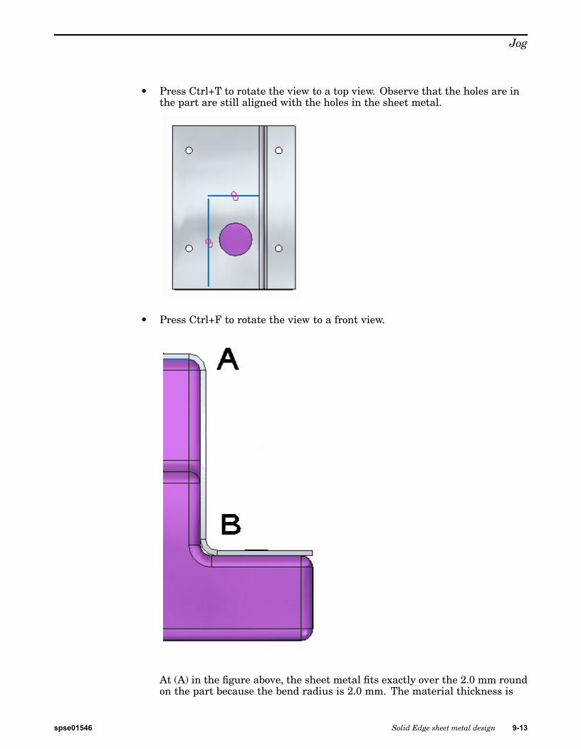
Jog
• Press Ctrl+T to rotate the view to a top view. Observe that the holes are inthe part are still aligned with the holes in the sheet metal.
• Press Ctrl+F to rotate the view to a front view.
At (A) in the figure above, the sheet metal fits exactly over the 2.0 mm roundon the part because the bend radius is 2.0 mm. The material thickness is
spse01546 Solid Edge sheet metal design 9-13

Lesson 9 Jog
1.0 mm. The outer radius is the sum of these two values and is 3.0 mm. Onthe bottom bend, (B) the sheet metal does not fit exactly because of this. Inthe next step the bend radius will be modified so that the sheet metal part iscorrectly positioned at (B).
▸ Press Ctrl+J to rotate the view. Select the bend shown, then click the text. Thiswill allow edits to the bend radius for that bend.
▸ Change the Bend Radius to 1.0 mm.
▸ Press Ctrl+F to rotate the view to a front view. Observe the bend.
9-14 Solid Edge sheet metal design spse01546

Jog
▸ Use the same steps to place a jog on the opposite side of the part and modify thebend radius on the lower bend. The result is as shown below.
spse01546 Solid Edge sheet metal design 9-15

Lesson 9 Jog
▸ Place the last jog using the remaining line in the sketch. Modify the bend radiuson the lower bend. The result is as shown below.
Using the cut command to trim unwanted edges
In this step the cut command will be used to trim away unwanted parts of thevertical flanges.
▸ Select the Project to Sketch command .
▸ Lock the sketch plane to the outer face of the vertical flange and include thefollowing geometry in the sketch:
9-16 Solid Edge sheet metal design spse01546

Jog
▸ Click the Trim Corner command and trim the lines so that they intersectand form a region.
▸ Select the region shown.
spse01546 Solid Edge sheet metal design 9-17

Lesson 9 Jog
▸ Selecting the region initiates the cut command. Set the Face Normal Cut Typesoption to Mid-Plane Cut and the Extent option to Through All.
9-18 Solid Edge sheet metal design spse01546

Jog
▸ Click the left arrow.
The flanges are trimmed.
▸ Right-click to finish the trim.
Using the cut command to trim unwanted edges
In this step the break corner command will be used to round the sheet metal corners.
Note The break corner command can be used to either round or chamfer a corner. Inthis activity a 2.0 mm round will be placed on each sheet metal corner.
▸ Click the Break Corner command .
spse01546 Solid Edge sheet metal design 9-19

Lesson 9 Jog
▸ On the command bar, set the Corner Type to Radius and the Selection Typeto Face.
▸ Select the 5 faces shown and enter a radius of 2.0 mm.
▸ The results are shown. This completes the activity.
9-20 Solid Edge sheet metal design spse01546

Jog
Activity summary
In this activity you created a sheet metal base feature and used the jog commandto form the sheet metal around and existing part. You modified the bend radiuswhere needed and then used the cutout command and the break corner command tofinish the model.
Lesson reviewAnswer the following questions:
1. What does the jog command do in a sheet metal document?
2. Explain the material side options when placing a jog?
Lesson summaryIn this lesson you created a sheet metal base feature and used the jog commandto form the sheet metal around and existing part. You modified the bend radiuswhere needed and then used the cutout command and the break corner command tofinish the model.
spse01546 Solid Edge sheet metal design 9-21


Lesson
10 Deformation features
Deformation features in a sheet metal part
Deformation features model features on the thickness faces of sheet metal parts, suchas louvers, beads, dimples, drawn cutouts, and gussets, that can be manufactured bystriking the stock with a tool. The values you use to define deformation features asyou create them are stored with the features, and you can edit them later. Also thefeature origin, or strike point, of the feature is positioned on the face such that ifthe face is later rotated or a jog is added, the feature will remained positioned. Thefeature can be relocated by modifying the position of the feature origin.
Deformation features consist of louvers, beads, dimples, drawn cutouts, and gussets.
Adding sheet metal deformation featuresYou can model features in the Sheet Metal environment that are manufactured withmetal deformation techniques, such as deep drawing and coining. When parts aremanufactured using deformation techniques, material thinning typically occurs.In Solid Edge, this material thinning is ignored and deformation features areconstructed using the same material thickness specified for the model.
spse01546 Solid Edge sheet metal design 10-1

Lesson 10 Deformation features
Constructing louvers
Like a jog feature, a louver feature is constructed using a single, linear element.
When constructing a louver, the louver height (H) must be equal to or less than thelouver depth (D) minus the material thickness (T).
You can also specify whether you want the louver ends formed (A) or lanced (B) usingthe Louver Options dialog box.
Louver features cannot be flattened.
10-2 Solid Edge sheet metal design spse01546

Deformation features
Constructing drawn cutouts
You can construct a drawn cutout using an open profile (A) or a closed profile (B).
The ends of an open profile must theoretically intersect a part edge. A closed profilecannot touch any part edges. A drawn cutout can be constructed only on a planarface. You can use the Drawn Cutout Options dialog box to specify punch radius,die radius, and taper options.
When you draw the profile for a drawn cutout without arcs, you also can specifywhether the corners are mitered (A), or rounded (B) using the Automatically RoundProfile Corners option on the Drawn Cutout Options dialog box.
When you construct a drawn cutout, the sidewalls are constructed such that theylie inside the profile (A). After the feature is constructed, you can use the optionsto specify that the sidewalls lie outside the profile (B).
Drawn cutouts cannot be flattened.
spse01546 Solid Edge sheet metal design 10-3

Lesson 10 Deformation features
Constructing dimples
Constructing a dimple is just like constructing a drawn cutout. The principaldifference between the two features is that a dimple has a "bottom" (A), and a drawncutout (B) does not.
Closing corners
The Close 2–Bend Corner command modifies two flanges in one operation to close acorner where two flanges meet.
In the ordered environment, the Close 3-Bend Corner command closes corners thatcontain three bends.
10-4 Solid Edge sheet metal design spse01546

Deformation features
A closed corner is a treatment feature. You do not have to draw a profile, just selectthe edges you want to modify. With 2-bend corners, you can specify whether to closethe corner (A), or overlap the corner (B).
Note The Overlap option is not available for 3-bend corners.
When you close the corner, you can also specify what type of bend treatment youwant. For example, you can specify that you want a circular cutout applied to thebent faces.
When you overlap a corner, select the bend to be overlapped.
In the ordered environment, when you overlap a corner, you can use the OverlapRatio option to compute the overlap as a percentage of the global material thickness.
spse01546 Solid Edge sheet metal design 10-5

Lesson 10 Deformation features
Note It is best to apply bend and corner relief before using the Close 2–Bends Cornercommand, so there is a clean corner to close. The corner should be symmetric,with equal bend radii and bend angles on the adjacent flanges. If there is morethan one way to close the corner, edit the flanges themselves to close the cornerthe way you want.
10-6 Solid Edge sheet metal design spse01546

Deformation features
Constructing beadsYou can construct a bead with an open sketch element,
or closed sketch region.
When constructing a bead profile using multiple elements, the element must bea continuous set of tangent elements.
You can also construct a bead feature using multiple, separate sketch elements.Each element must be a continuous set of tangent elements, but the profiles cancross each other.
spse01546 Solid Edge sheet metal design 10-7

Lesson 10 Deformation features
You can select more than one sketch element to construct multiple beads in a singleoperation.
You can use the direction arrow to change the direction of the beads.
All disjoint beads created in a single operation offset to the same side.
When constructing multiple disjoint beads, an entry in PathFinder, a feature profile,and a nail is created for each disjoint bead. Beads cannot be flattened and theycannot cross a bend.
You can specify the shape of the bead cross section and the type of end conditiontreatment you want using the Bead Options dialog box. For example, you can specifywhether the bead shape is circular, U-shaped, or V-shaped. You can also specifywhether the ends of the bead are formed, lanced, or punched.
10-8 Solid Edge sheet metal design spse01546

Deformation features
Constructing gussets
You can use the Gusset command to add support across a bend. In the synchronousenvironment, you can construct gussets automatically across a bend. In the orderedenvironment, you can either construct gussets automatically or you can constructthem from a drawn profile.
Note Gussets are not displayed in the flat pattern representation or in drawingviews of the flat pattern in the Draft environment.
You can use the Gusset Options dialog box to specify the definition of the gusset. Youcan control such things as the shape of the gusset, the width and taper angle of thegusset, and the punch and die radius if the gusset is rounded. You can also use thedialog box to specify if the gusset is created automatically or from a user-drawnprofile.
Constructing gussets automatically in the ordered environment
Select the Automatic Profile option on the Gusset Options dialog box toautomatically create a gusset. Once you select a bend, the gusset profile isautomatically displayed along the bend.
spse01546 Solid Edge sheet metal design 10-9

Lesson 10 Deformation features
You can then click a keypoint to place the gusset,
or, use the Pattern Type option to specify whether you want to place one gussetor a pattern of gussets. For example, you can use the Fit option to place threegussets that are equally spaced along the selected edge.
Constructing gussets from a user-drawn profile in the ordered environment
Select the User—Drawn Profile option on the Gusset Options dialog box to usea drawn profile to create a gusset. The profile can be an existing sketch or youcan draw the profile while in the Draw Profile step.
To create a gusset from a user-drawn profile:
10-10 Solid Edge sheet metal design spse01546
Deformation features
1. Click a keypoint to create a plane on which you want to draw the profile.
Note You may select an existing sketch to define the gusset profile and skipto step 3.
2. Draw the profile.
3. Click to define the direction of the gusset.
spse01546 Solid Edge sheet metal design 10-11

Lesson 10 Deformation features
4. Click Finish to place the gusset.
When using the User-Drawn Profile option, you can also you can draw a profile thatconstructs a gusset across two bends,
or, across a non-linear bend.
10-12 Solid Edge sheet metal design spse01546

Deformation features
Constructing cross brakes
In the ordered environment, you can use the Cross Brake command to stiffen a sheetmetal panel. The command creates a set of bends from a sketch that is coincident tothe sheet metal part face.
A cross brake feature does not deform the 3D model. It adds attributes containinginformation about the bends. This attribute information is used when creating a flatpattern or drawing of the sheet metal part.
To create a cross brake feature:
1. Select the face on which you want to construct the cross brake.
2. Select the sketch(es) you want to use to construct the cross brake.
spse01546 Solid Edge sheet metal design 10-13

Lesson 10 Deformation features
3. Specify the bend angle and direction for the cross brake.
4. Click Finish to construct the cross brake.
Louver commandConstructs a louver with lanced or formed ends.
In the ordered environment, the profile for a louver feature must be a single linearelement. Louvers cannot be flattened.
10-14 Solid Edge sheet metal design spse01546

Deformation features
Dimple commandConstructs a sheet metal dimple from a selected region. If you use an open profile,the open ends of the profile must theoretically intersect part edges. Dimples arespecial die-formed features in which material deformation occurs. Dimples cannotbe flattened.
Drawn Cutout commandConstructs a drawn cutout.
In the ordered environment, if you use an open profile, the open ends of the profilemust theoretically intersect part edges. A closed profile cannot touch any part edges.Drawn cutouts cannot be flattened.
In the synchronous environment, the geometry used to create the cutout can be aclosed internal profile that creates a region or an open profile extended to a partedge to create a closed region.
In the synchronous environment, regions that are valid for drawn cutouts are:
• Single
spse01546 Solid Edge sheet metal design 10-15

Lesson 10 Deformation features
• Disjoint
• Contiguous
• Coincident to a sketch or edge
• Nested contiguous
10-16 Solid Edge sheet metal design spse01546

Deformation features
You can select multiple regions at one time and the regions must all lie on the sameplane.
Bead commandConstructs a bead feature on a sheet metal part. A bead feature is often usedto stiffen a sheet metal part.
In the ordered environment, you can construct a bead with an open
or closed profile.
In the synchronous environment, you can construct a bead with an open sketchelement,
spse01546 Solid Edge sheet metal design 10-17
Lesson 10 Deformation features
or closed sketch region.
When constructing a bead profile using multiple elements, the element must bea continuous set of tangent elements.
Gusset commandConstructs a stiffening gusset across a bend to provide reinforcement in a sheetmetal part.
You can create a gusset automatically or from a user-drawn profile. You can usethe Gusset Options dialog box to specify the method to use when constructing thegusset. The steps required to construct the gusset are different depending on themethod you use.
Note Gussets are not displayed in the flat pattern representation or in drawing viewsof the flat pattern in the Draft environment. If the resident bend is removed, thegusset is also removed.
10-18 Solid Edge sheet metal design spse01546

Deformation features
For more information on constructing gussets, see Adding sheet metal deformationfeatures.
Working with feature originsYou can use the feature origin handle to move or rotate manufactured features thatcontain a feature origin. The feature origin provides a reference point that can beused to move a feature without changing its shape.
The feature origin is used primarily in sheet metal models (.psm) for features suchas dimples, drawn cutouts, and louvers.
Note A feature origin is also used for hole features in part and sheet metaldocuments. The feature origin for a hole feature does not have XY fins.
You can dimension to a feature origin, and then edit the dimensional value to movethe entire feature.
Note When using Smart Dimension to dimension to a feature origin you cannotselect the feature origin first.
Show and Hide commands are available to display and hide the feature origin whenyou select a feature that contains a feature origin. You can also display and hideall the features origins in a document.
Shortcut menu commands are available to reposition the feature origin for a feature.
spse01546 Solid Edge sheet metal design 10-19
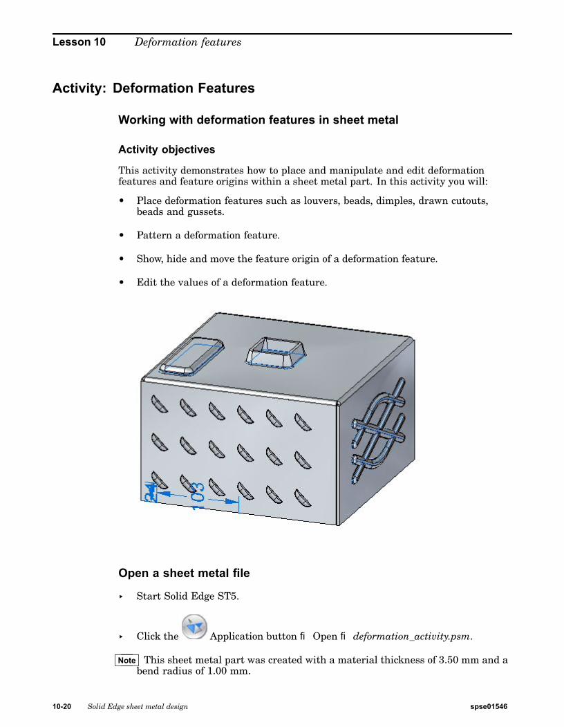
Lesson 10 Deformation features
Activity: Deformation Features
Working with deformation features in sheet metal
Activity objectives
This activity demonstrates how to place and manipulate and edit deformationfeatures and feature origins within a sheet metal part. In this activity you will:
• Place deformation features such as louvers, beads, dimples, drawn cutouts,beads and gussets.
• Pattern a deformation feature.
• Show, hide and move the feature origin of a deformation feature.
• Edit the values of a deformation feature.
Open a sheet metal file
▸ Start Solid Edge ST5.
▸ Click the Application button® Open® deformation_activity.psm.
Note This sheet metal part was created with a material thickness of 3.50 mm and abend radius of 1.00 mm.
10-20 Solid Edge sheet metal design spse01546

Deformation features
Place a louver on the front face
▸ Select the Louver command .
▸ Click the Louver options button on the command bar.
Note The louver depth cannot be greater than half the louver length. The louverheight cannot be greater than the material thickness.
▸ Enter the following values:
• Type: Formed-end louver
• Length: 25.00 mm
• Depth: 8:00 mm
• Height: 4.00 mm
• Turn on rounding and set the die radius to 0.88 mm.
Click OK.
spse01546 Solid Edge sheet metal design 10-21

Lesson 10 Deformation features
▸ Move the cursor over the front face and observe the behavior.
Note The length of the louver is parallel with an edge the plane that the cursoris positioned over. The N (next) and B (back) keys can be used to cyclethrough the plane edges. The louver will orient itself to be parallel to theedge displayed. When the desired orientation is achieved, the F3 key willlock the louver to that plane and in the orientation chosen.
Orient the louver as shown by entering N as needed. Once the orientation isestablished, enter F3 to lock to the face and orientation.
Note Once the plane and orientation has been set can be positioned with a leftmouse click, or my using dimensions to precisely locate the louver. In thenext step, the louver will be located using dimensions.
10-22 Solid Edge sheet metal design spse01546

Deformation features
▸ Move the cursor over the edge shown below and press the E key.
Note To position using dimensions, entering the character E dimensions fromthe endpoint of an edge and entering the character M dimensions from themidpoint of an edge.
spse01546 Solid Edge sheet metal design 10-23

Lesson 10 Deformation features
▸ Move the cursor over the edge shown below and enter M from the keyboard.
Note Notice the dimension originating from the end of the previous edge chosen.
10-24 Solid Edge sheet metal design spse01546

Deformation features
▸ Without clicking the mouse, move the cursor to the approximate position shownbelow.
spse01546 Solid Edge sheet metal design 10-25

Lesson 10 Deformation features
▸ For the horizontal dimension value enter 95.00 mm, and for the verticaldimension value enter 24.00 mm as shown. Use the Tab key to toggle betweenfields, then press Enter.
10-26 Solid Edge sheet metal design spse01546

Deformation features
▸ The louver is placed.
Feature Origin
The origin of a feature is called the feature origin, and is also referred to as thestrike point for manufacturing purposes and which can be shown and detailed inSolid Edge Draft. The feature origin can be offset upon creation, or offset afterplacement. The feature origin can also be used to apply a rotation angle to a rigidprocedural feature such as a louver. In the following steps, the feature origin of thelouver just created will be moved and rotated.
spse01546 Solid Edge sheet metal design 10-27

Lesson 10 Deformation features
▸ In PathFinder right-click and select Show Feature Origin.
The feature origin appears.
The values for the louver will be edited in the following steps.
10-28 Solid Edge sheet metal design spse01546

Deformation features
▸ Click the louver feature in PathFinder. When displayed, click the edit handleas shown.
▸ Click the Louver Options button. Change the Y value of the feature origin offsetto 8.00 mm, then click OK.
spse01546 Solid Edge sheet metal design 10-29

Lesson 10 Deformation features
The feature origin changes position.
Note Notice that only the feature origin changed position. The louver is stilllocated in the same position.
Now the louver will be rotated 45 degrees.
10-30 Solid Edge sheet metal design spse01546

Deformation features
▸ Select the louver, then select the torus of the steering wheel.
▸ Rotate the louver 45o as shown.
spse01546 Solid Edge sheet metal design 10-31
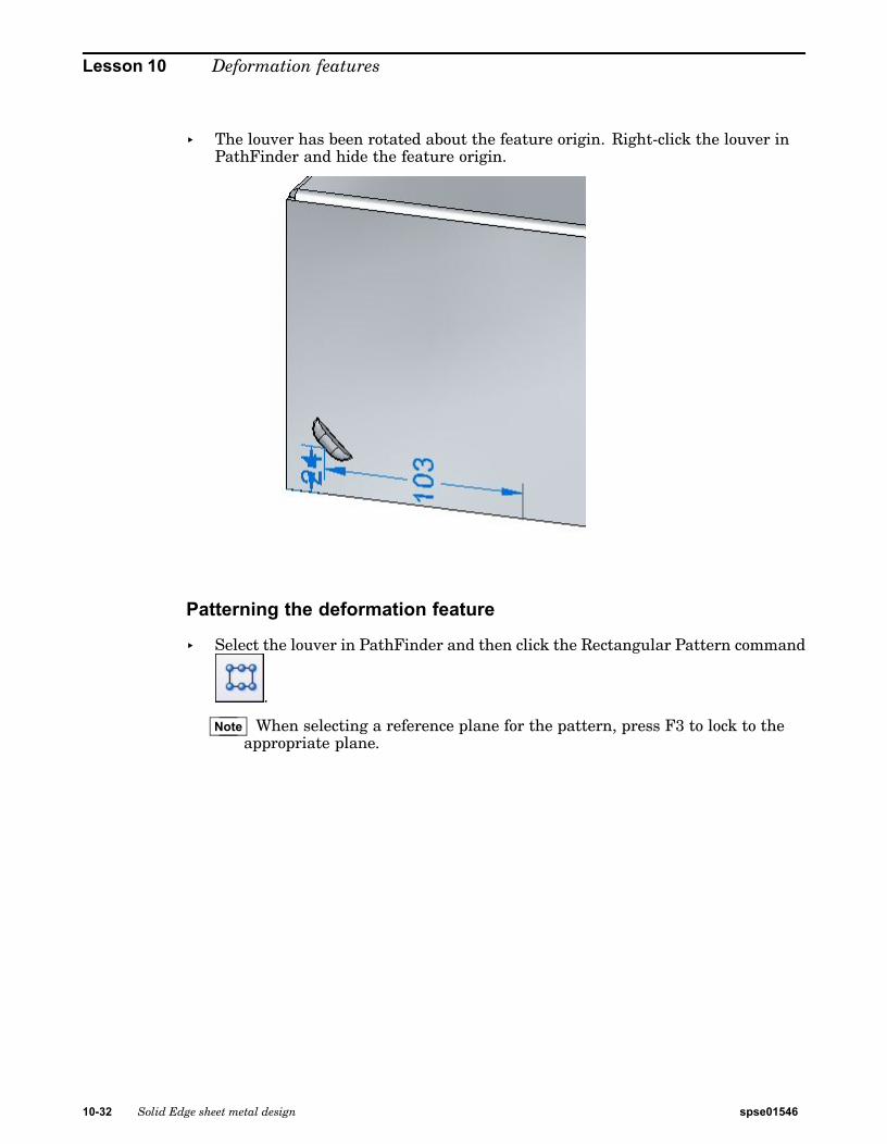
Lesson 10 Deformation features
▸ The louver has been rotated about the feature origin. Right-click the louver inPathFinder and hide the feature origin.
Patterning the deformation feature
▸ Select the louver in PathFinder and then click the Rectangular Pattern command
.
Note When selecting a reference plane for the pattern, press F3 to lock to theappropriate plane.
10-32 Solid Edge sheet metal design spse01546

Deformation features
▸ Set the pattern parameters as follows:
• Type: Fit
• X count: 6
• Y count: 3
• Vertical distance: 95.00 mm.
• Horizontal distance: 180.00 mm.
▸ Click the accept button to finish creating the rectangular pattern.
Placing Beads
Beads are added to sheet metal parts as stiffeners.
spse01546 Solid Edge sheet metal design 10-33

Lesson 10 Deformation features
▸ In PathFinder, display the sketch named Beads.
▸ Click the Bead command .
▸ Click the Bead Options command .
▸ Set the following options:
• Cross section: U-Shaped.
• Height: 4.00 mm.
• Width: 3.50 mm.
• Angle: 20o.
• End Condition: Formed.
• Include rounding with a punch radius of 0.50 mm, and a die radius of 0.50mm.
• Click OK.
10-34 Solid Edge sheet metal design spse01546

Deformation features
▸ Select all the elements in the sketch as shown.
Note Clicking the arrow will reverse the direction of the beads.
▸ Right mouse click to accept the beads. The beads are created.
Placing dimples and drawn cutouts
In this step you will place a dimple and a drawn cutout from a two different sketches.
spse01546 Solid Edge sheet metal design 10-35

Lesson 10 Deformation features
▸ In PathFinder, display the sketch named Drawn.
▸ Click the Drawn Cutout command .
▸ Click the Drawn Cutout Options command .
▸ Set the following options:
• Taper angle: 15o.
• Include rounding: die radius 1.75 mm.
• Include punch side corner radius: 1.75 mm..
• Click OK.
10-36 Solid Edge sheet metal design spse01546

Deformation features
▸ Select the region shown.
▸ Enter a distance of 15.00 mm.
Note Clicking the arrow will reverse the direction of the drawn cutout.
spse01546 Solid Edge sheet metal design 10-37

Lesson 10 Deformation features
▸ Right mouse click to accept the drawn cutout. The drawn cutout is created.
▸ In PathFinder, display the sketch named Dimple.
▸ Click the Dimple command .
▸ Click the Dimple Options button .
▸ Observe the options, but do not change any of the options.
▸ Change the sketch profile to represent punch as shown
10-38 Solid Edge sheet metal design spse01546
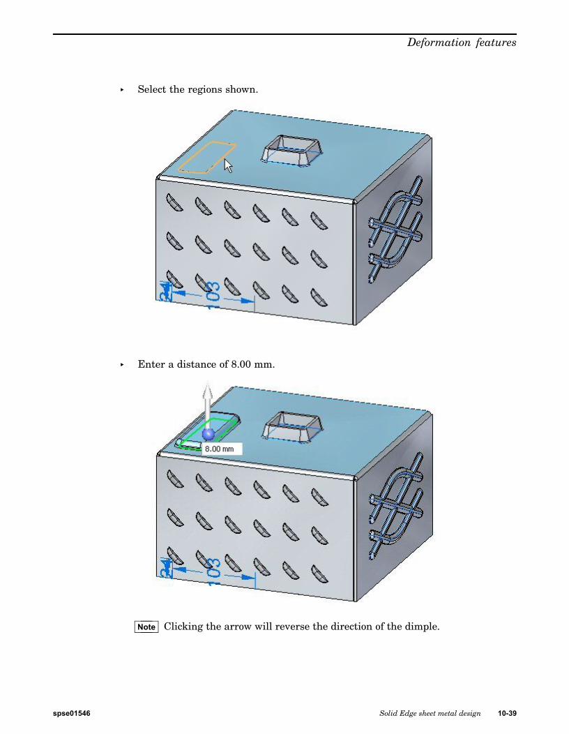
Deformation features
▸ Select the regions shown.
▸ Enter a distance of 8.00 mm.
Note Clicking the arrow will reverse the direction of the dimple.
spse01546 Solid Edge sheet metal design 10-39

Lesson 10 Deformation features
▸ Right-click to accept the dimple. The dimple is created.
Editing deformation features
In this step you will edit the bead feature created in an earlier step.
▸ In PathFinder, select the bead feature. Click the edit handle to edit the feature.
10-40 Solid Edge sheet metal design spse01546

Deformation features
▸ Click the Edit Profile Handle.
▸ Select the line shown.
▸ Drag the endpoint of the line to a new position. Click the green check mark andthen right-click.
spse01546 Solid Edge sheet metal design 10-41

Lesson 10 Deformation features
▸ The deformation feature has been edited.
Note When editing a rigid procedural feature, the sketch used to create the featureremains a part of the feature and can be modified at a later time.
▸ Save and close the sheet metal document.
Placing a single gusset
In this step you will place gussets between two thickness faces.
▸ Click the Application button® Open® gusset_activity.psm.
▸ Click the Gusset command .
▸ Click the Gusset Options button .
▸ Set the following parameters:
• Depth: 11.25 mm.
• Include rounding with the both the punch and die radius being 1.50 mm.
• Set the gusset shape to round.
• Set the width to 9.00 mm. Click OK.
▸ Set the gusset patterning parameter to single.
10-42 Solid Edge sheet metal design spse01546

Deformation features
▸ Select the bend shown.
▸ Click the midpoint shown to place the gusset.
▸ Right-click to complete the placement. The gusset is placed.
Rotating faces containing gussets
In this step you will rotate a face containing a gusset and observe how the gussetresponds.
spse01546 Solid Edge sheet metal design 10-43

Lesson 10 Deformation features
▸ Click the Select tool and select he face shown.
▸ Move the steering wheel to the bend as shown and select the torus so as to rotatethe face.
▸ Enter an angle of 30o as shown.
10-44 Solid Edge sheet metal design spse01546

Deformation features
The result is as shown.
Note The gusset is an adaptive procedural feature that will change shape to asthe angle between the faces changes.
Placing a gusset pattern
In this step you will place multiple gussets along a bend.
▸ Click the Gusset command .
▸ Click the Gusset Options button .
▸ Set the following parameters:
• Depth: 11.25 mm.
• Include rounding with the both the punch and die radius being 1.50 mm.
• Set the gusset shape to round.
• Set the width to 9.00 mm. Click OK.
▸ Set the gusset patterning parameter to fit.
▸ Select the bend shown.
spse01546 Solid Edge sheet metal design 10-45

Lesson 10 Deformation features
▸ set the count to 8. Observe the results.
▸ Set the pattern type to fill. Observe the results.
▸ Set the pattern type to fixed. Set the count to 10 and the distance to 22.00 mm.
▸ Right-click to complete the gusset pattern. Observe the results.
10-46 Solid Edge sheet metal design spse01546

Deformation features
▸ Save and close the sheet metal document. This concludes this activity.
Activity summary
In this activity you created a variety of deformation features. The feature origin fora rigid procedural feature was displayed and moved to a new location. The featurewas rotated. Multiple occurrences where created with the pattern command.
Lesson reviewAnswer the following questions:
1. What is the definition of a deformation feature?
2. What is the difference between a drawn cutout and a dimple?
Lesson summaryIn this lesson you created a variety of deformation features. The feature origin for arigid procedural feature was displayed and moved to a new location. The feature wasrotated. Multiple occurrences where created with the pattern command.
spse01546 Solid Edge sheet metal design 10-47


Lesson
11 Creating flat patterns
Manipulating sheet metal geometry
After constructing a sheet metal part, you may need to create a flat pattern of thepart for manufacturing.
Flattening sheet metal partsAfter constructing a sheet metal part, you can use the Flatten and Save As Flatcommands to create a flat pattern of a sheet metal part.
Using the Flatten command
Use the Tools tab®Flat group®Flatten command in the Sheet Metal environmentto create a flat pattern in the same file as the formed sheet metal part.
When you flatten a sheet metal part with the Flatten command, a Flat Patternfeature is added to the PathFinder tab.
If the sheet metal model changes, the flat pattern becomes outdated. This isindicated by a symbol adjacent to the Flat Pattern feature in PathFinder. To updatethe flat pattern, select the Flat Pattern feature in PathFinder, then on the shortcutmenu click Update.
spse01546 Solid Edge sheet metal design 11-1
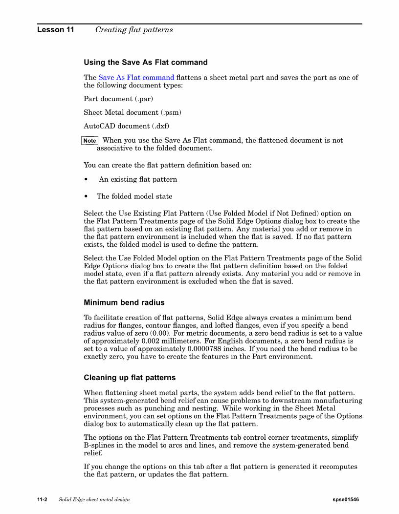
Lesson 11 Creating flat patterns
Using the Save As Flat command
The Save As Flat command flattens a sheet metal part and saves the part as one ofthe following document types:
Part document (.par)
Sheet Metal document (.psm)
AutoCAD document (.dxf)
Note When you use the Save As Flat command, the flattened document is notassociative to the folded document.
You can create the flat pattern definition based on:
• An existing flat pattern
• The folded model state
Select the Use Existing Flat Pattern (Use Folded Model if Not Defined) option onthe Flat Pattern Treatments page of the Solid Edge Options dialog box to create theflat pattern based on an existing flat pattern. Any material you add or remove inthe flat pattern environment is included when the flat is saved. If no flat patternexists, the folded model is used to define the pattern.
Select the Use Folded Model option on the Flat Pattern Treatments page of the SolidEdge Options dialog box to create the flat pattern definition based on the foldedmodel state, even if a flat pattern already exists. Any material you add or remove inthe flat pattern environment is excluded when the flat is saved.
Minimum bend radius
To facilitate creation of flat patterns, Solid Edge always creates a minimum bendradius for flanges, contour flanges, and lofted flanges, even if you specify a bendradius value of zero (0.00). For metric documents, a zero bend radius is set to a valueof approximately 0.002 millimeters. For English documents, a zero bend radius isset to a value of approximately 0.0000788 inches. If you need the bend radius to beexactly zero, you have to create the features in the Part environment.
Cleaning up flat patterns
When flattening sheet metal parts, the system adds bend relief to the flat pattern.This system-generated bend relief can cause problems to downstream manufacturingprocesses such as punching and nesting. While working in the Sheet Metalenvironment, you can set options on the Flat Pattern Treatments page of the Optionsdialog box to automatically clean up the flat pattern.
The options on the Flat Pattern Treatments tab control corner treatments, simplifyB-splines in the model to arcs and lines, and remove the system-generated bendrelief.
If you change the options on this tab after a flat pattern is generated it recomputesthe flat pattern, or updates the flat pattern.
11-2 Solid Edge sheet metal design spse01546

Creating flat patterns
Managing flat pattern size
Use the Flat Pattern Options dialog box to set the maximum flat pattern sizeand issue a warning if that size is violated. This is useful if a part cannot bemanufactured because of sheet size limitations.
The Current section of the dialog box displays the length and width of the currentflat pattern. These values are read-only and cannot be changed manually. They areupdated when the values change in the flat model and the model is updated. TheAlarm section allows you to specify the maximum length and width values for theflat pattern. You can specify a maximum length, maximum width, or both. Youcan either key in these values or use default values that are specified on the FlatPattern Treatments page on the Options dialog box. If the flat pattern violates thesesize limitations, an alarm icon is displayed adjacent to the flat pattern entry inPathFinder. If you pause the cursor over the flat pattern entry, a tool tip displays thecurrent flat pattern size along with the maximum size limitations.
You can use the Show Cut Size Range and Dimensions option to display a range boxfor the flat pattern along with the dimensions for the current length and width of theflat pattern. The size of the pattern is determined when the flat pattern is createdand is recalculated when the flat model is updated.
Flattening deformation features
If you want to remove a deformation feature after you flatten a part using theFlatten and Part Copy commands, you can construct a cutout feature that is sizedaccording to the area the deformation feature occupied. In many cases, you can usethe Include command to create a cutout profile that is associatively linked to theedges of the deformation feature. Later, if the deformation feature changes, thecutouts also update. This approach maintains the true position for the deformationfeature, which can be useful for creating downstream manufacturing documentation.
Alternatively, you can use the commands on the command bar to remove thedeformation features prior to or after you flatten the part. For example, you can usethe Delete Faces command to delete a deformation feature. The deformation featureis not physically deleted from the part, it is still available when working in the SheetMetal environment. With this approach, the location of the deformation feature islost in the flattened version of the part.
Displaying deformation features in the flat pattern
You can use the options in the Formed Feature Display section of the Flat PatternTreatments page to specify how deformation features are displayed in the flatpattern.
You can display the deformation features as a formed feature,
spse01546 Solid Edge sheet metal design 11-3
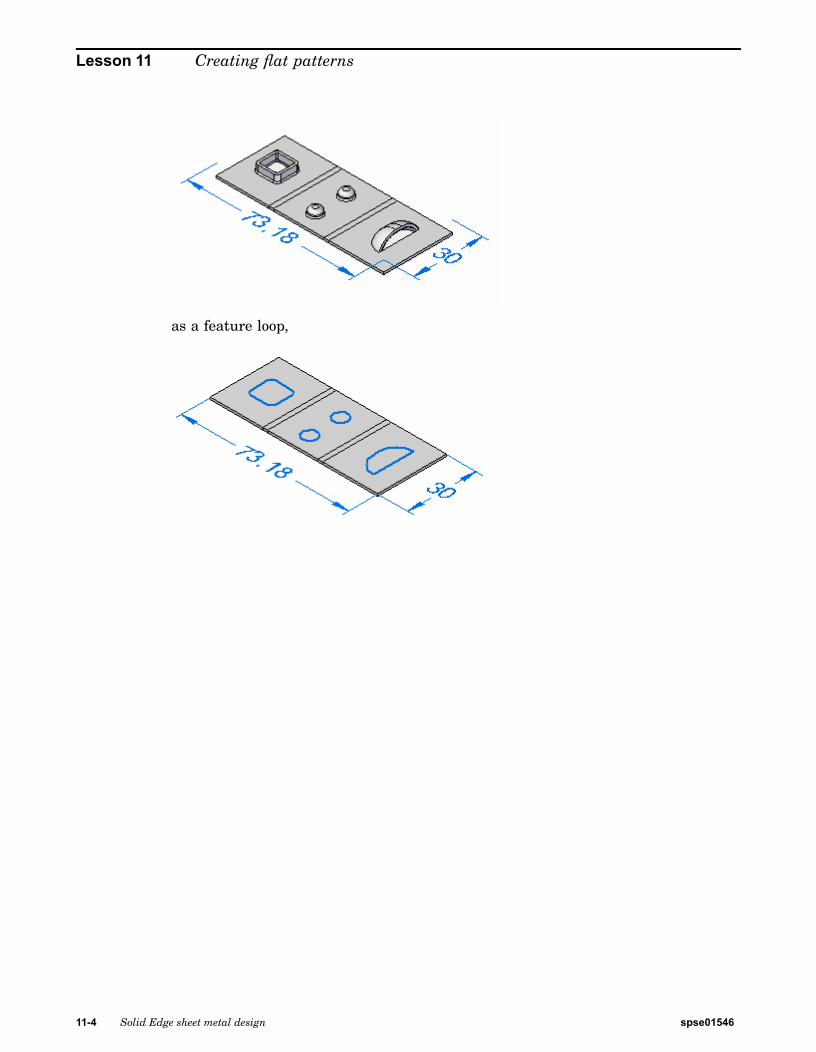
Lesson 11 Creating flat patterns
as a feature loop,
11-4 Solid Edge sheet metal design spse01546

Creating flat patterns
as a feature origin,
or as a feature loop and feature origin.
Saving deformation features to other files
The Formed Feature Display section of the Flat Pattern Treatments page specifieshow deformation features are exported when you use the Save as Flat to flatten thesheet metal model and save it to another document.
When saving the document to .prn or .psm format:
• As Formed Feature replaces the deformed feature with a cutout the size of thearea consumed by the feature.
• As Feature Loops replaces the loops representing the deformation feature witha curve.
• As Feature Origin does not export the deformation feature or the feature origin.
• As Feature Loops and Feature Origin replaces the loops representing thedeformation feature with a curve and feature origins are not exported.
When saving the document to .dxf format:
• As Formed Feature replaces the deformed feature with a 2D wireframerepresentation as they would appear in the formed condition.
• As Feature Loops replaces the loops representing the deformation feature with acurve and are specified as either an up or down feature.
• As Feature Origin does not export the deformation feature or the feature origin.
spse01546 Solid Edge sheet metal design 11-5

Lesson 11 Creating flat patterns
• As Feature Loops and Feature Origin replaces the loops representing thedeformation feature with a curve and are specified as either an up or downfeature. Feature origins are not exported.
Flattening lofted flanges
Only lofted flanges that consist of planes, partial cylinders, and partial cones can beflattened. Lofted flanges that contain ruled surfaces cannot be flattened. The type ofgeometry constructed depends upon how you draw the profiles.
A lofted flange is constructed by mapping the faces between corresponding profileelements. For example, profile lines A1 and B1 are mapped to construct planar faces.Profile arcs A2 and B2 are mapped to construct conical faces.
If the two profiles have the same number and type of elements, and each element onthe first profile maps to the same element type on the second profile (line to line, orarc to arc), in most cases, you can flatten it.
11-6 Solid Edge sheet metal design spse01546

Creating flat patterns
Ruled surface examples
Any lofted flange that contains a ruled surface cannot be flattened. The followingexamples describe when a ruled surface is constructed:
• A face constructed where line A1 has a different angle relative to line B1.
• A face constructed where arc A2 has a different start angle or included anglerelative to arc B2.
• A face constructed using an arc and a line.
Note If the lofted flange contains faces that would prevent it from being flattened, agray arrow is displayed adjacent to the feature on the PathFinder tab. If youpause your cursor over the feature in PathFinder, a message is displayed inthe status bar describing the problem.
PMI dimensions in the flat pattern
When a flat pattern is created, PMI dimensions are placed as driven dimensions. Inother words, these dimensions are for reference only and cannot be changed whilein the flat pattern. If you select a PMI dimension in the flat pattern, all fields onthe dimension edit control are disabled. If you make changes to the model, the PMIdimensions are updated when the flat pattern updates.
Adding material to the flat pattern
You can use the Tab command to add material to a flat pattern.
Any tabs created in the flat pattern are placed in the flat pattern node of PathFinder.Any material added to the flat pattern appears only in the flat pattern state. Thefolded model will not reflect the material addition.
spse01546 Solid Edge sheet metal design 11-7

Lesson 11 Creating flat patterns
Saving sheet metal files as AutoCAD documents (.dxf)
When you save a sheet metal part as an AutoCAD document (.dxf), it is saved as2D. Collinear and concentric arcs are merged into single elements. Bend lines areadded as wireframe bodies.
Layers are used to separate the various types of information such as bends,deformation features, and edges. A layer scheme defines the information that isstored on the different layers.
• Default or Normal edges are saved to layers named Outer_Loop andInterior_Loops. All edges from flanges, contour flanges, lofted flanges, tabs,cutouts, and sheet metal cutouts are placed on these layers. The layers cancontain visible and hidden edges.
• Bend down centerlines are saved to a layer named DownCenterlines. This layercontains the bend centerlines of all linear and conical bends that are in the downdirection relative to the selected output face. These lines are generated in theflatten process and do not exist in the model. The line style associated with benddown centerlines can be saved to this layer.
• Bend up centerlines are saved to a layer named UpCenterlines. This layercontains the bend centerlines of all linear and conical bends that are in the updirection relative to the selected output face. These lines are generated in theflatten process and do not exist in the model. The line style associated with bendup centerlines can be saved to this layer.
• Deformation features found on down bends are output to a layer namedDownFeatures. This layer contains the edges of all deformation features thatare in the down direction relative to the selected output face. This layer cancontain visible and hidden edges.
• Deformation features found on the up bends are output to a layer namedUpFeatures. This layer contains the edges of all deformation features that arein the up direction relative to the selected output face. This layer can containvisible and hidden edges.
Creating flat pattern drawings
You can create drawings of flattened sheet metal parts in the Draft environment.A special template can be applied when a flat pattern drawing is created. Thistemplate has tangent edges displayed so that the lines that represent the edges ofthe bends (A) are shown in the drawing.
11-8 Solid Edge sheet metal design spse01546

Creating flat patterns
To apply the template, you must run the Drawing View Wizard and set the Part andSheet Metal Drawing View Options on the first page of the Drawing View CreationWizard to Flat Pattern.
You also can display tangent edges in a drawing that was created with a differenttemplate. Use the Edge Display tab on the Solid Edge Options dialog box.
The flat pattern created with the Flatten command contains all bend centerlineinformation used to create bend centerlines in drawing views.
In draft, you also can add the centerline to a bend (A) using the By Two Lines optionwith the Center Line command.
Specifying bend options
In part, sheet metal, and draft, you can use the options on the Annotation page(Solid Edge Options dialog box) to:
• Customize bend direction strings for Up, Down, and Undefined bends.
spse01546 Solid Edge sheet metal design 11-9

Lesson 11 Creating flat patterns
• Create and assign independent styles to bend up centerlines and to bend downcenterlines.
• Specify which part face is the top face in the flat pattern drawing view. Bydefault, bend direction is derived from the face that is designated the top facewhen a sheet metal part is flattened. In draft, you can keep the model benddirection properly aligned with the flattened drawing view using the DeriveBend Direction from Drawing View option.
Updating flat pattern drawings
When you make design changes to a folded sheet metal part, you need to update theassociatively flattened part first, and then update the flattened drawing to see thechanges. When you open the flattened part document, an out of date symbol isdisplayed adjacent to the base feature in the PathFinder tab. To update the flattenedpart, select the Flat Pattern entry in PathFinder, then use the Update commandon the shortcut menu.
When you open the drawing of the flattened part, a box is displayed around eachdrawing view to indicate that they are out of date. To update the drawing views, usethe Update Views command.
11-10 Solid Edge sheet metal design spse01546
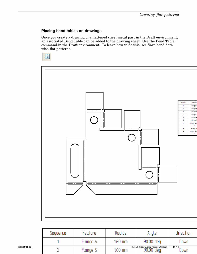
Creating flat patterns
Placing bend tables on drawingsOnce you create a drawing of a flattened sheet metal part in the Draft environment,an associated Bend Table can be added to the drawing sheet. Use the Bend Tablecommand in the Draft environment. To learn how to do this, see Save bend datawith flat patterns.
spse01546 Solid Edge sheet metal design 11-11

Lesson 11 Creating flat patterns
Construct a flat pattern in the sheet metal part document1. Select Tools tab®Model ® Pattern.
2. Select Tools tab®Flat group®Flatten .
3. Click a face to be oriented upward in the flat.
4. Click an edge to define the X axis and origin.
Note The definition of the X axis is aligned or orientated with the Global X-axisof the sheet metal file.
5. Click to complete the flat pattern.
11-12 Solid Edge sheet metal design spse01546

Creating flat patterns
Tip
• After flattening, you can use this command multiple times to adjust theorientation by selecting a new edge for alignment.
• When you create a flat pattern, a Flat Pattern tab is added to PathFinder.You can delete the flat pattern by deleting the Flat Pattern entry in the FlatPattern tab of PathFinder.
• If the Sheet Metal model changes, the flat pattern will go out-of-date. This isindicated with a clock symbol overlapping the Flat Pattern tab in PathFinder.To update the flat pattern, click the Flat Pattern tab in PathFinder.
• You can add PMI dimensions to the flat pattern.
• The flat pattern created with the Flatten command contains all bendcenterline information used to create bend centerlines in Draft drawingviews. It also contains the same information used by the Save As Flatcommand.
• You can use the Flat Pattern Options dialog box to set a maximum flatpattern size. If the flat pattern violates the maximum size a warning iconis displayed adjacent to the flat pattern entry in PathFinder. This can helpyou determine whether or not the part can be manufactured due to sheetsize limitations.
• You can use the Simplify B-Splines option on the Flat Pattern Treatmentstab on the Options dialog box to specify that any b-spline curves in the partare simplified to lines and arcs when creating the flat pattern. B-splinecurves can be created when creating cutouts across bends and when usingstencil font characters.
Flatten commandFlattens a sheet metal part in the same document as the design model. The flattenedversion of the part is associative to the formed version of the part.
spse01546 Solid Edge sheet metal design 11-13

Lesson 11 Creating flat patterns
You can use the Flat Pattern Treatments tab on the Options dialog box to controloutput parameters for the flat pattern. For example, you can specify that anyB-spline curves in the formed part are simplified to lines and arcs when creatingthe flat pattern. B-spline curves can be created when creating cutouts across bendsand when using stencil font characters.
Note When you use this command to construct the flat pattern, Solid Edge placesa Flat Pattern entry in PathFinder.
Note Note: When you use this command to construct the flat pattern, Solid Edgeplaces a Flat Pattern tab and entry in PathFinder.
Save As Flat commandFlattens the sheet metal part and saves it to a document type you define. You canspecify that the part is saved as a .par, .psm, or .dxf file.
You can create the flat pattern definition based on:
• An existing flat pattern
• The folded model state
You can use the options on the Flat Pattern Treatments page of the Solid EdgeOptions dialog box to specify how to define the flat pattern. You can also use optionsto specify how deformation features are displayed in the flat pattern.
Use Save As Flat when a flat pattern of a Solid Edge sheet metal file is needed in .dxfformat. The resulting 3D planar geometry is merged wherever possible to providea more efficient tool path for CNC programming. A drawing can be produced fromthe geometry generated by this process. However, it will neither be associative norlinked to the 3D sheet metal file from which it derives.
Note Bend lines are not automatically created with this command. If you want toautomatically create bend lines, you must use the Insert Part Copy commandto create a flat .psm file. You can then place a part view for the flat .psm filein a draft file.
11-14 Solid Edge sheet metal design spse01546

Creating flat patterns
Activity: Creating a flat pattern from a sheet metal part
Creating a flat pattern from a sheet metal part
Activity objectives
This activity demonstrates how to create a flat pattern from a sheet metal part, andthe various options available. In this activity you will:
• Create a flat pattern from a sheet metal part.
• Control the orientation of the flat pattern.
• Understand the options available for using the flat pattern with downstreammanufacturing applications.
Open a sheet metal file
▸ Start Solid Edge ST5.
▸ Click the Application button® Open® flatpattern_activity.psm.
spse01546 Solid Edge sheet metal design 11-15

Lesson 11 Creating flat patterns
Creating a flat pattern
▸ Click Tools®Model®Flat Pattern.
▸ Click Tools®Flat®Flatten.
The Flat Pattern command bar displays.
11-16 Solid Edge sheet metal design spse01546
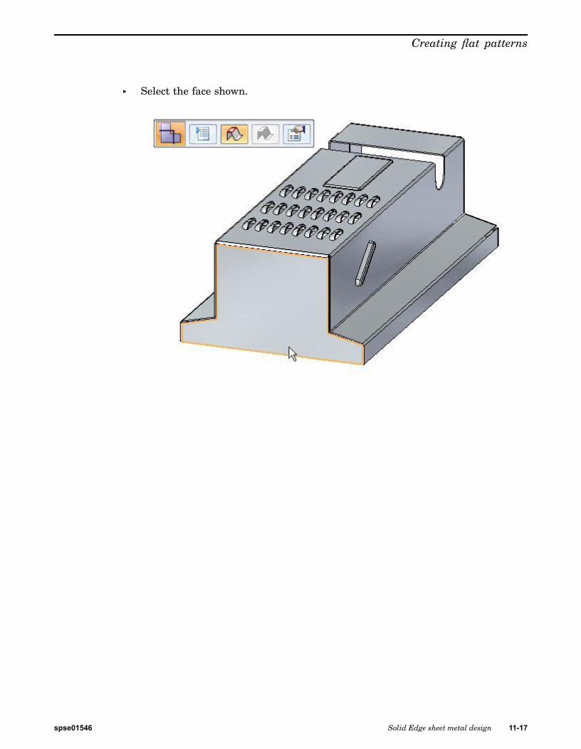
Creating flat patterns
▸ Select the face shown.
spse01546 Solid Edge sheet metal design 11-17

Lesson 11 Creating flat patterns
▸ Select the edge shown to orient the flat pattern.
Note The edge selected defines the x axis of the flat pattern.
The flat pattern is created.
Note Notice there is a new tab in PathFinder for the flat pattern.
Flat pattern options
▸ Click the Flat Pattern Cut Size button.
11-18 Solid Edge sheet metal design spse01546

Creating flat patterns
▸ Observe the following on this dialog box.
• The cut size of the flat pattern dimensions can be displayed.
• Alarms can be set to notify if the cut size is larger than a desired size.
• The current cut size is displayed if this command is chosen in the flattenedstate rather than the design state.
Close the dialog box.
▸ Click the Flat Pattern Treatment Options button.
Note The flat pattern treatment options can also be set by clicking the applicationbutton and then clicking Solid Edge Options.
▸ Set Outside Corner Treatments to Chamfer and set the value to 4.00 mm. ClickApply. Observe the results. Chamfers are applied to the exterior corners thatdo not contain rounds.
Note This corner treatment only shows up in the flattened state and not in thedesigned state.
spse01546 Solid Edge sheet metal design 11-19

Lesson 11 Creating flat patterns
▸ Set Formed Feature Display to As Feature Loops and Feature Origin and clickApply. Observe the results.
Note When placing a flat pattern onto a drawing sheet in Solid Edge Draft, thisdisplay controls the what geometry is placed. If the sketches or 3D geometryis desired on the drawing sheet, the option will need to be set here.
▸ Set Formed Feature Display to As Feature Origin and click Apply. Observe theresults.
▸ Save the file.
Saving the flat pattern as a .dxf or .par file
▸ Click the Application menu.
▸ Click Save as®Save as Flat.
▸ Save the file as my_flat.dxf.
Note Some numerical control machines can read a .dxf file directly. The flat patterncan also be saved as a Solid Edge part file.
Placing a flat pattern on a drawing sheet
▸ Click the Application button.
▸ Click New®Create Drawing.
11-20 Solid Edge sheet metal design spse01546

Creating flat patterns
▸ Use the default template and ensure the Run Drawing View Creation Wizardbutton is checked.
▸ In the Drawing View Creation Wizard, click the Flat Pattern option in Drawingview options. Click next.
▸ In Drawing View Orientation, use the top view and then click next.
▸ Click Finish and place the flat pattern on the drawing sheet.
Note The feature origins, or strike points, for the deformation features aredisplayed. These can precisely located by dimensioning.
Note The display of tangent edges on the drawing view represent the locationof the edges of bends.
▸ Close the sheet metal documents without saving.
Activity summary
In this activity you created a flat pattern and changed the display options. You alsoplaced the flat pattern on a drawing sheet.
Lesson reviewAnswer the following questions:
1. Describe the steps needed to create a flat pattern.
2. When saving a flat pattern using the save as flat command, what file typesare available?
3. What is a feature origin on a flat pattern?
spse01546 Solid Edge sheet metal design 11-21

Lesson 11 Creating flat patterns
Lesson summaryIn this lesson you created a flat pattern and changed the display options. You alsoplaced the flat pattern on a drawing sheet.
11-22 Solid Edge sheet metal design spse01546