Solar Array Suspension Mechanism Final Design Report for ...
77
Solar Array Suspension Mechanism Final Design Report for ATK Space Presented by Alex Gould Randon Kruse Jeremy Graul Patrick Barney [email protected] Mechanical Engineering Department California Polytechnic State University San Luis Obispo June 3 rd , 2010
Transcript of Solar Array Suspension Mechanism Final Design Report for ...
So l a r A r r a y Su s p en s i o n Mechan i sm
F i n a l De s i g n Repo r t
f o r ATK Sp a c e
P r e s e n t e d b y
Alex Gould Randon Kruse Jeremy Graul Patrick Barney
Mechanical Engineering Department
California Polytechnic State University
San Luis Obispo
June 3rd, 2010

P a g e | 2

P a g e | 3
Statement of Disclaimer
Since this project is a result of a class assignment, it has been graded and accepted as fulfillment of the
course requirements. Acceptance does not imply technical accuracy or reliability. Any use of information
in this report is done at the risk of the user. These risks may include catastrophic failure of the device or
infringement of patent or copyright laws. California Polytechnic State University at San Luis Obispo and
its staff cannot be held liable for any use or misuse of the project.

P a g e | 4
T ab l e o f Con t en t s
List of Figures ..................................................................................................................................................... 6
List of Tables ...................................................................................................................................................... 8
Abstract ............................................................................................................................................................. 9
Introduction ...................................................................................................................................................... 10
1 Background .............................................................................................................................................. 10
1.1 Purpose and function ................................................................................................................................. 10
2 Components ............................................................................................................................................. 12
2.1 Spring ......................................................................................................................................................... 12
2.2 Force Gauge ............................................................................................................................................... 13
2.3 Adjustment Mechanisms ............................................................................................................................ 14
2.4 SASM Connection Mechanism .................................................................................................................... 15
3 Objectives ................................................................................................................................................. 16
4 Method of Approach ................................................................................................................................. 19
5 Design Development ................................................................................................................................. 20
5.1 Spring ......................................................................................................................................................... 20
5.2 Force Gauge ............................................................................................................................................... 21
5.3 Adjustment Mechanism ............................................................................................................................. 24
5.3.1 Compressed Spring Adjustment ............................................................................................................ 25
5.3.2 ACME Threaded Screw with Collar ........................................................................................................ 26
5.3.3 Screw Jack .............................................................................................................................................. 27
5.4 Connection Mechanism .............................................................................................................................. 27
5.4.1 Carabiner ............................................................................................................................................... 29
5.4.2 Pneumatic Hose Coupling ...................................................................................................................... 29
5.4.3 Swivel Nub ............................................................................................................................................. 30
5.4.4 Socket Stud ............................................................................................................................................ 31
5.4.5 U Loop .................................................................................................................................................... 31
5.5 Ergonomic Tests ......................................................................................................................................... 32

P a g e | 5
6 Manufacturing .......................................................................................................................................... 33
6.1 Machined Swivel Nub ................................................................................................................................. 33
6.2 Casted Swivel Nub ...................................................................................................................................... 35
6.3 Socket Stud ................................................................................................................................................. 37
6.4 Compression Spring Adjustment ................................................................................................................ 38
7 Design Verification (Testing) ..................................................................................................................... 39
7.1 Approach and Methodology ....................................................................................................................... 39
7.2 Test Descriptions and Results ..................................................................................................................... 40
8 Final Design .............................................................................................................................................. 43
8.1 Assembly Description ................................................................................................................................. 43
8.2 Adjustment / Spring Mechanism Description ............................................................................................. 45
8.3 Socket Stud Description .............................................................................................................................. 46
8.4 Future Build Considerations ....................................................................................................................... 46
8.5 Analysis Results .......................................................................................................................................... 47
8.6 Cost Breakdown ......................................................................................................................................... 49
9 Conclusion ................................................................................................................................................ 51

P a g e | 6
L i s t o f F i g u re s
Figure 1. Off‐loader configuration looking directly down the Y‐axis .......................................................... 11
Figure 2. Offloader Assembly1 containing Undeployed Solar Panels. ........................................................ 11
Figure 3. Current SASM configuration1 ....................................................................................................... 11
Figure 4. Hydraulic spring ........................................................................................................................... 12
Figure 5. Drawbar Compression Spring ...................................................................................................... 12
Figure 6. Force gauge with Wi‐Fi data output ............................................................................................ 13
Figure 7. Spring force gauge ....................................................................................................................... 13
Figure 8. Retractable Cord .......................................................................................................................... 14
Figure 9. Rack and Pinion ............................................................................................................................ 14
Figure 10. Carabiner .................................................................................................................................... 15
Figure 11. Grasper and Binder Ring ............................................................................................................ 16
Figure 12. Design Process ........................................................................................................................... 19
Figure 13. Required Load Cell Configuration .............................................................................................. 23
Figure 14. Compressed Spring Adjustment ................................................................................................ 25
Figure 15. ACME Thread Sketch .................................................................................................................. 26
Figure 16. Screw Jack .................................................................................................................................. 27
Figure 17. Pneumatic Hose Coupling Assembly Cross Section ................................................................... 30
Figure 18. Swivel Nub .................................................................................................................................. 30
Figure 19. Socket Stud ................................................................................................................................ 31
Figure 20. U‐Loop Concept Assembly ......................................................................................................... 31
Figure 21. Ergonomic Test Set Up ............................................................................................................... 32
Figure 22. Ergonomic Test Results .............................................................................................................. 33
Figure 23. Swivel Nub Manufacturing ......................................................................................................... 33
Figure 24. Manufactured Swivel Nub Top .................................................................................................. 34
Figure 25. Manufactured Swivel Assembly ................................................................................................. 35
Figure 26. Curved Slot and Cast Support Bar .............................................................................................. 35
Figure 27. Swivel and Support Patterns .............................................................................................. 36
Figure 28. Casted Swivel Nub ...................................................................................................................... 36
Figure 29. First Socket Stud prototype ....................................................................................................... 37
Figure 30. Final Socket Stud prototype ....................................................................................................... 37

P a g e | 7
Figure 31. Spring Adjustment Mechanism Exploded View ......................................................................... 38
Figure 32. Manufacturing process of the Compression Spring Adjustment Mechanism ........................... 39
Figure 33. Cooling of the Socket Stud ......................................................................................................... 40
Figure 34. Room Temperature Tensile Testing ........................................................................................... 41
Figure 35. Cryogenic Tensile Testing ........................................................................................................... 41
Figure 36. Socket Stud Stress vs. Strain Graph ........................................................................................... 42
Figure 37. Strain Testing on Socket Stud .................................................................................................... 42
Figure 38. SASM Final Assembly ................................................................................................................. 43
Figure 39. Spring Adjustment Mechanism Exploded View ......................................................................... 45
Figure 40. Compression Spring Section View .............................................................................................. 45
Figure 41. Socket Stud Assembly ................................................................................................................ 46
Figure 42. Failure Point Compared to FEA .................................................................................................. 48

P a g e | 8
L i s t o f Tab l e s
Table 1. Design Specifications ..................................................................................................................... 17
Table 2. Spring Decision Matrix .................................................................................................................. 21
Table 3. Force Gauge Decision Matrix ....................................................................................................... 22
Table 4. Adjustment Mechanism Decision Matrix ..................................................................................... 25
Table 5. Connection Mechanism Decision Matrix ...................................................................................... 28
Table 6. Room Temperature and Cryogenic Test Data ............................................................................... 41
Table 7. Final Specification Table ................................................................................................................ 44
Table 8. Factor of Safety for Each Component ........................................................................................... 48
Table 9. Cost estimate for one SASM device .............................................................................................. 50

P a g e | 9
Ab s t r a c t
The purpose of this project is to improve the existing Solar Array Suspension Mechanism used by ATK
Space for the manufacturing and testing of deployable solar arrays. The current system requires too
much time to operate and has too many removable parts that may fall and damage the solar arrays.
Through the design and verification process the team successfully constructed a quick connecting
suspension mechanism that requires no tools to use and has no removable parts. The final design
includes the existing force gauge and large adjustment bars used by ATK Space with the addition of a
compression spring adjustment mechanism and a Socket Stud connection mechanism. The system was
proof loaded at 300 lbs without any components yielding. The lowest factor of safety is about 5.2,
which can be found on the Socket Stud. The estimated cost of the system is $2900, which is significantly
less than the specified $8000 maximum cost.

P a g e | 10
I n t r o d u c t i o n
The purpose of this project is to improve the existing Solar Array Suspension Mechanism used by ATK
Space, a premier aerospace and defense company located in Goleta, California, for the manufacturing
and testing of deployable solar arrays. The current system requires too much time to operate and has
too many removable parts that may fall and damage the solar arrays which would result in an expensive
and time intensive repair by ATK Space. The team consists of four California Polytechnic State
University, San Luis Obispo mechanical engineering students, Jeremy Graul, Alex Gould, Randon Kruse
and Patrick Barney. The team developed improvements to both the connection mechanism and the
suspension adjustments. This report documents the teams design, manufacturing and verification
processes showing how the final design meets and exceeds the design specifications given by ATK.
1 B a c k g r o u n d
1 . 1 P u r p o s e a n d f u n c t i o n
The current Solar Array Suspension Mechanism (SASM) created and used by ATK functions not only as a
mechanical support for the arrays, but as a leveling system. The deployment arm requires this support
because it is not designed to support the weight of the solar panels in earth’s gravity. In order to support
the deployment arm, multiple suspension mechanisms are connected to the pivot points between each
panel as seen in Figure 2. These support mechanisms keep the solar array panels level by a series of
coarse and fine adjustment components, along with a force gauge. It is critical that the solar modules
stay level in respect to one another during deployment in order to avoid high concentrated loads on the
panels which could cause damage. The suspension mechanisms move with the arrays and are free to
move on raised rollers on the off‐loader track seen in Figure 1 in the deployment direction, x and the
lateral direction, y until the arrays are fully deployed. The lateral directional movements as seen are
needed because the arrays do not offload in a straight chord. The individual components of the current
SASM mechanism can be seen in Figure 3, along with the sub‐categories in which these components fall
into, which are used to organize the research.

P a g e | 11
Figure 2. Offloader Assembly1 containing Undeployed Solar Panels.
Current sub‐categories and component include:
1. Spring
a. Tension Spring
2. Force Gauge
a. Analogue Ring Gauge
3. Adjustment Mechanism
a. Turnbuckle
4. Connection Mechanism
a. Ball Bearing Swivel and Clevis
Figure 1. Off‐loader configuration looking directly down the Y‐axis
1 ATK Corporation
Figure 3. Current SASM configuration1

P a g e | 12
Figure 4. Hydraulic spring
2 C ompo n e n t s
2 . 1 S p r i n g
Currently the SASM uses a mechanical helical spring in order to absorb loads caused by forced
deflection. These deflections can arise during normal operation and testing. The joints located on the
solar panel array are, by design, incapable of handling large internal stresses and moments. Thus even a
small deflection can cause damage to the system. The force spring allows the SASM to change its height
with only a small amount of force generated.
The current problems with the spring involve its physical size. The spring was sized to handle the global
yield strength condition. In result, the spring is the widest component, which limits storage of the
devices. Thus, any design improvement would concentrate on reducing the spring diameter. This is also
a problem during deployment when the SASM need to be right next to each other. Not only does the
helical spring limit how close each suspension mechanism can get, but the spring itself also has the
potential of mechanically locking up with either spring located next to it.
A possible redesign consideration is a hydraulic or gas spring as
seen in Figure 4. Hydraulic and gas springs can be made with
much smaller outer diameters while maintaining similar
yielding forces as a conventional helical stainless spring, such
as the one currently used.
Another possible redesign is known as a drawbar and can be seen in Figure 5. This method would
replace the tension spring with a compression spring, and has a built in safety mechanism which could
take the place of the metal wire in the current method which ties the force gauge directly to the
overhead railing during max load testing.
Figure 5. Drawbar Compression Spring
P a g e | 13
2 . 2 F o r c e Ga u g e
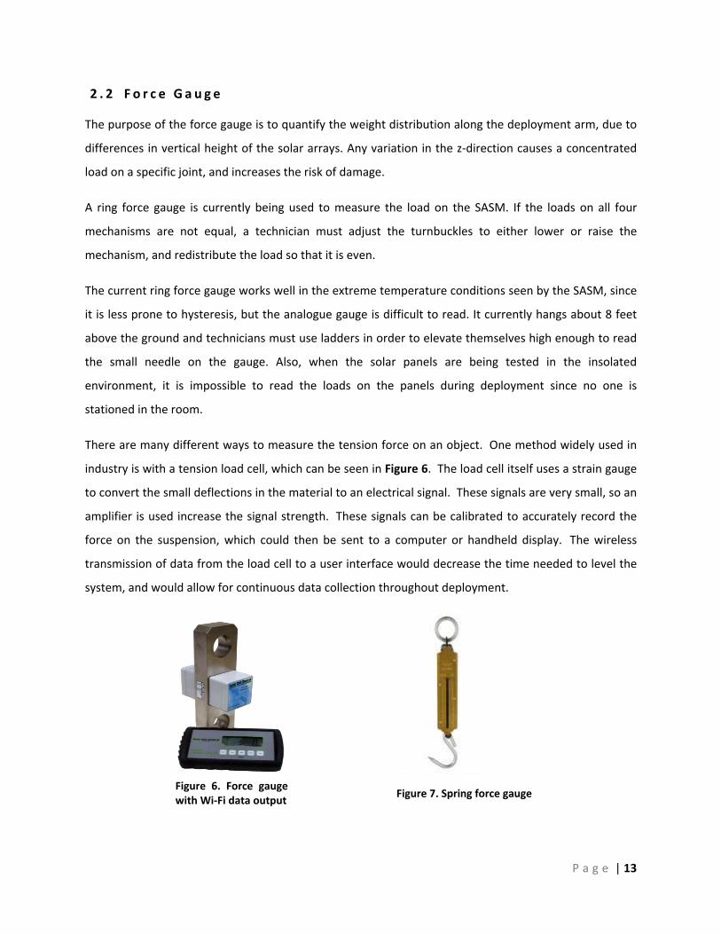
The purpose of the force gauge is to quantify the weight distribution along the deployment arm, due to
differences in vertical height of the solar arrays. Any variation in the z‐direction causes a concentrated
load on a specific joint, and increases the risk of damage.
A ring force gauge is currently being used to measure the load on the SASM. If the loads on all four
mechanisms are not equal, a technician must adjust the turnbuckles to either lower or raise the
mechanism, and redistribute the load so that it is even.
The current ring force gauge works well in the extreme temperature conditions seen by the SASM, since
it is less prone to hysteresis, but the analogue gauge is difficult to read. It currently hangs about 8 feet
above the ground and technicians must use ladders in order to elevate themselves high enough to read
the small needle on the gauge. Also, when the solar panels are being tested in the insolated
environment, it is impossible to read the loads on the panels during deployment since no one is
stationed in the room.
There are many different ways to measure the tension force on an object. One method widely used in
industry is with a tension load cell, which can be seen in Figure 6. The load cell itself uses a strain gauge
to convert the small deflections in the material to an electrical signal. These signals are very small, so an
amplifier is used increase the signal strength. These signals can be calibrated to accurately record the
force on the suspension, which could then be sent to a computer or handheld display. The wireless
transmission of data from the load cell to a user interface would decrease the time needed to level the
system, and would allow for continuous data collection throughout deployment.
Figure 7. Spring force gauge Figure 6. Force gauge with Wi‐Fi data output

P a g e | 14
Another method of measuring tension force could be with a spring scale, which is shown in Figure 7.
These springs are effective, but can have hysteresis problems, which cause them to be constantly
calibrated. Also, using this type of spring would require a technician to look directly at the spring to take
the reading, and reading a spring scale would be more difficult than reading the current ring scale.
2 . 3 Ad j u s tm e n t Me c h a n i sm s
The current adjustment system is broken down into either coarse or fine adjustments. The coarse
adjustments utilize a combination of different length bars with holes drilled into them for screw
attachments. The bars are inserted during the build of the apparatus, and are not modifiable while the
panels are being hung from the SASM. While not in use, these large bars take up lab space, and are not
convenient to change out, once the assembly is built. On the other hand, fine adjustments are used
frequently between loads, and utilize a turn buckle to either raise or lower the panels by fractions of an
inch. The same risks involving excess parts and components mentioned earlier apply to the adjustment
mechanisms as well. The current turn buckle must be operated with a wrench, which increases the risk
of damage on the panels due to tools being dropped.
One method of approach is to eliminate the distinction between coarse and fine adjustment
components, and utilize a single component to meet both functions. An example of this could involve a
locking, retractable cord as seen in Figure 8, or a system of pulleys. By having only one mechanism
which controls the height of the panels without the use of tools, the time needed to operate decreases,
along with the risk of damage.
Another method of approach would be to leave the coarse adjustment bars the way they are, since they
are not used much, and focus on replacing only the fine adjustment components. One method of
approach the team looked into includes replacing the turnbuckle with a rack and pinion as seen in Figure
Figure 9. Rack and Pinion Figure 8. Retractable Cord

P a g e | 15
Figure 10. Carabiner
9. But the rack and pinion can be broken down farther into a purely mechanical based system and an
electric powered one.
The idea of bringing in electricity in order to remotely control fine adjustments has also been
researched. If servos or linear actuators can be used to either move the SASM directly, or power a rack
and pinion couple, the team would eliminate the risk of damaging the solar arrays completely, and also
save the technicians the time spent on making fractional changes on precise instruments. But the added
risk of running wires to each SASM is hypothesized to be problematic.
2 . 4 S A SM C o n n e c t i o n Mec h a n i sm
The current connection between the SASM and the solar array utilizes a swivel composed of modified
eye bolt and screw in order to connect to the clevis, which is mounted to the panels. The SASM is first
pulled down until the components line up with one another and then the screw is inserted through the
eye bolt and clevis to make a positive, reliable connection. Even though this connection has been proven
to be robust, it has its disadvantages. The amount of time required to screw and unscrew the eye bolt
from the clevis are excessive and adds risk to the testing environment. The use of loose screws and
additional tooling to adjust the screws increase the risk of damage to the solar panels. These excess
parts are easily dropped, and if they crack a solar panel, the cost to replace them is significant.
In order to rid the assembly of the previously stated downfalls regarding the connection mechanism, the
team looked into other methods of connection which were reliable, quick, and required no tools or
loose parts to operate.
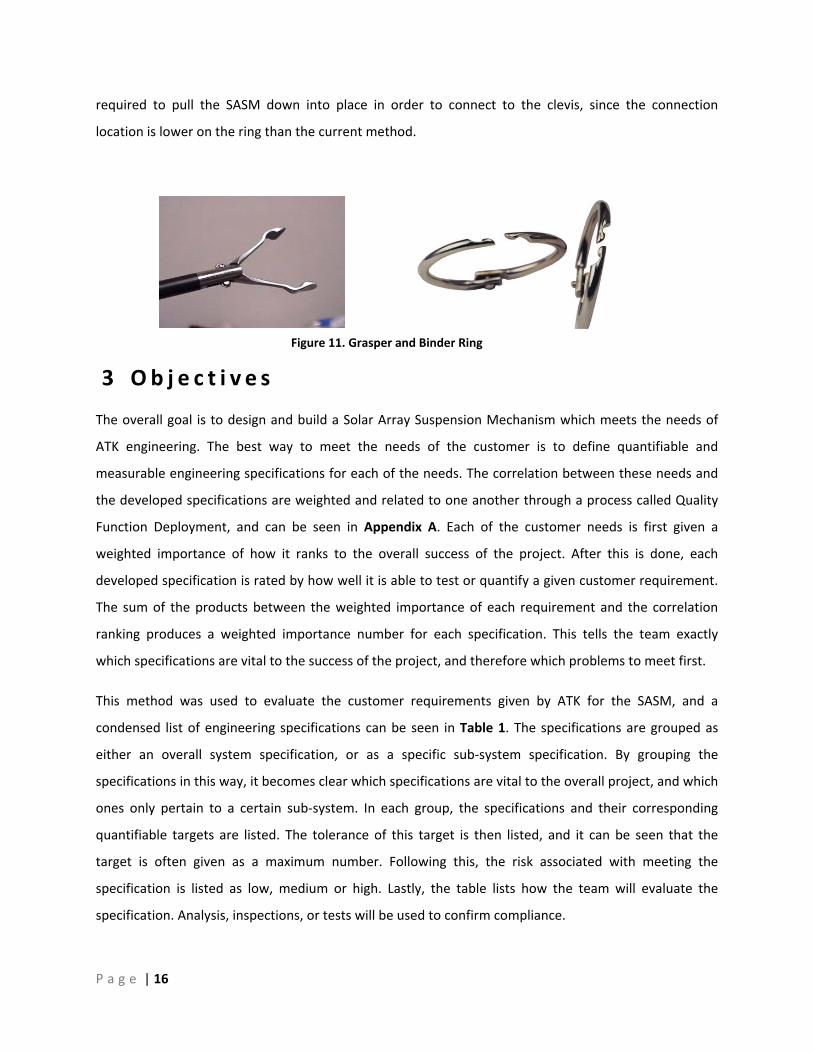
One promising device the group explored is the common day carabiner. The
carabiner utilizes a metal loop with a screwed gate in order to quickly connect two
components together in a single operation. As seen in Figure 10, carabiners can
also have a locking mechanism to secure it from accidentally opening. This locking
mechanism would make the connection between the SASM and panels easily
verifiable and secure.
Another quick connect mechanism which does not require tools to operate is a grasper as seen in Figure
11. A specific use of this in our daily lives can be seen in the typical binder ring. These rings can be easily
operated with a single hand, and can be integrated with a locking mechanism similar to that of a
carabiner, in order to secure the connection. Another advantage of the binder ring is that less force is
P a g e | 16
Figure 11. Grasper and Binder Ring
required to pull the SASM down into place in order to connect to the clevis, since the connection
location is lower on the ring than the current method.
3 Ob j e c t i v e s
The overall goal is to design and build a Solar Array Suspension Mechanism which meets the needs of
ATK engineering. The best way to meet the needs of the customer is to define quantifiable and
measurable engineering specifications for each of the needs. The correlation between these needs and
the developed specifications are weighted and related to one another through a process called Quality
Function Deployment, and can be seen in Appendix A. Each of the customer needs is first given a
weighted importance of how it ranks to the overall success of the project. After this is done, each
developed specification is rated by how well it is able to test or quantify a given customer requirement.
The sum of the products between the weighted importance of each requirement and the correlation
ranking produces a weighted importance number for each specification. This tells the team exactly
which specifications are vital to the success of the project, and therefore which problems to meet first.
This method was used to evaluate the customer requirements given by ATK for the SASM, and a
condensed list of engineering specifications can be seen in Table 1. The specifications are grouped as
either an overall system specification, or as a specific sub‐system specification. By grouping the
specifications in this way, it becomes clear which specifications are vital to the overall project, and which
ones only pertain to a certain sub‐system. In each group, the specifications and their corresponding
quantifiable targets are listed. The tolerance of this target is then listed, and it can be seen that the
target is often given as a maximum number. Following this, the risk associated with meeting the
specification is listed as low, medium or high. Lastly, the table lists how the team will evaluate the
specification. Analysis, inspections, or tests will be used to confirm compliance.

P a g e | 17
Table 1. Design Specifications
Overall System Specifications Spec # Parameter Description Requirement or Target (units) Tolerance Risk Compliance
1 Number of Tools Required 0 Max M A 2 Quantity of Loose parts 0 Max L I 3 # of Actions Required to Operate 3 actions Max M T 4 Visibility of Parts All (High) N/A L I 5 Width Dimensions 1.3 Inches Max L I 6 Load Allowable 100 lb +200lb L T 7 Cost $8,000 Max L A 8 Weight 8 lb Max L A,T 9 Temperature Range -80 C to 50 C Range M T 10 Clean Room Compatible 0 Intrusive Elements Max L I,A
Specific Force Gauge Specifications Spec # Parameter Description Requirement or Target (units) Tolerance Risk Compliance
11 Time To Check Force Gauge 5 seconds Max H T 12 Force Gauge Resolution 1 lb +/- 0.5lb L I
Specific Adjustment Mechanism Specifications
Spec # Parameter Description Requirement or Target (units) Tolerance Risk Compliance13 Operation Time of Adjustments 30 Seconds Max L T 14 Pitch Resolution 1/14" +/-1/28 L I
Specific Quick Connect Specifications
Spec # Parameter Description Requirement or Target (units) Tolerance Risk Compliance15 Operation Time for Connecting 5 seconds Max M T 16 Unload / Loading Deflection 3/4 inch +/- 1/4" M I
In order for the overall system to be compliant with ATK requirements, there are 10 different
specifications which much be met. The first and most important specification is that the new design
must not require the use of tools. The current design uses screwdrivers and wrenches in both the quick
connect and adjustment sub‐systems, which adds excessive risk and time to the deployment operation.
Furthermore, in order to stay compliant, the overall system must not rely on any loose parts such as
screws, washers, or nuts. These loose parts can easily fall and damage the solar array, thus adding risk to
the deployment procedure. A third overall system specification is the need to reduce the number of
operations to three. As part of these three actions, the team is counting the current process of loading
the SASM by pulling it down to the proper loading height as an action. This leaves only two actions, one
for the quick connect and one for the possible adjustment. This is shown as a medium risk specification
because the additional safety measures possibly needed on both connection and adjustment
mechanisms may increase the number of operations beyond the specification. The forth global

P a g e | 18
specification is the high visibility of all components. By having all parts visible, it will be easier to confirm
a positive connection between parts. The rest of the global specifications are all self explanatory and
have a low risk of completion except for the broad temperature range specification. This extreme
temperature range proposes problems when designing the force gauge, which will be discussed next.
When designing the force gauge sub‐system, two more specifications must be kept in mind in addition
to the global specs just mentioned. The more risky of the two is the specification to be able to make a
force gauge measurement within 5 seconds during any point of any deployment. It is important for ATK
to know if the weight distribution of the solar arrays becomes unbalanced during any part of the
deployment. This shifted weight could be adding unwanted stress to the panel hinges, resulting in
damage. But the only plausible method to make force gauge measurements during thermal testing
when temperatures reach ‐80° is if the measurement is wirelessly transmitted to an operator who is out
of the test environment. As stated earlier, the global specification of being able to operate in extreme
temperatures proposes a high risk for battery operated components, and in particular, the force gauge.
In addition to the global specs, there are an additional two specifications specific to the adjustment
mechanism. The first one is that it can be operated in less than 30 seconds. It is important that the
operator can easily and successfully distribute the solar array’s weight among all the suspension
mechanisms in a timely manner in order to reduce risk. The more time the operator is up on the ladder,
making adjustments, the greater the chance for something to get bumped or stressed. The second
specification is that the fine adjustment pitch must be on the order of 1/28” in order to fine tune the
displacements enough to eliminate unequal weight distribution.
Lastly, the quick connect sub‐system has an additional two specifications which need to be discussed. In
order for the quick connect to be considered “quick”, the team placed a time limit of 5 seconds onto the
operation. This time includes any additional steps necessary to insert safety locks, which is why there is
medium risk associated with meeting this specification in full. The second specification is relevant to the
loading and unloading steps of the solar arrays to the quick connect. Currently, in order to load the
SASM, the mechanism must be pulled down an inch in order for the hole in the u‐loop to be coaxial with
the clevis hole. Due to the large spring constant, it is difficult to pull down the mechanism any further
than an inch, which means that the quick connect must be able to connect to the panels without
excessive loading to position it correctly.

P a g e | 19
For further detail on how the team has evaluated the current design and where improvements can be
made, refer to the QFD, house of quality in Appendix A.
4 Me t h o d o f Ap p r o a c h
The project presented is an excellent example of a
product that can be reengineered using the classic
engineering design process. This method of engineering
is often described as an iterative decision making
process that can be outlined by Figure 12. This process
was started prior to our group receiving this project
when ATK concluded that there was a deficiency within
their manufacturing line where an improvement could
be made. As soon as the project was presented to the
team, the engineering process continued at full speed.
The second step of the design process is defining the
problem. The specifications aforementioned were created in partnership with ATK to better understand
the requirements of the project in order to confirm the spectrum of the project. This portion of the
design process specifically requires background information on existing devices used for this and similar
applications, and the objectives and goals for this project. Iteration of the research, objectives and
specifications may need to take place in the future with constantly evolving ideas. This is true for each
step of the design process to be mentioned.
The next section of the engineering design process is called synthesis. This involves the creation of ideas
and prototypes. Concept generation techniques are used to create a number of possible solutions.
Sketches and simple analysis help reduce the number of solutions to three to five prominent concepts.
Once the final design is narrowed down to one or two designs, CAD is used to generate 3‐D models to
help with further analysis and decision making. Throughout this process, prototypes can be produced in
order to determine feasibility and practicality.
The next step to the design process is the iteration process of fabrication of prototypes, analysis and
optimization of said prototypes, and evaluation of the design. This process is repeated multiple times
until the most ideal product is produced. It is important to keep ATK in close communications with the
Figure 12. Design Process
P a g e | 20
team throughout the design process so no surprises or miscommunication can occur. After the most
ideal device is created and tested rigorously, the final step of the engineering design process will be
completed and a final project report and presentation of the product.
5 De s i g n De v e l o pmen t
After extensive research of existing springs, quick connect, adjustment, and force gauge components,
team members created conceptual models of ideas which had potential of meeting the engineering
specifications. In order to distinguish which of these concepts conformed to the engineering
specifications the best, the team constructed a decision matrix for each of the four sub‐categories. The
matrices quantify the improvement of each concept over its existing design. This was done by awarding
the concepts a +1 if it met a specific specification better than the existing, a ‐1 if the concept was less
likely to meet a specification, or a 0 if both existing design and concept meet the specification equally.
But since certain specifications are more important to the overall success of the project, a weight was
added to each specification in order to better quantify its importance. This weighted number was then
multiplied by the initial score of either 1 through ‐1, and the sum of the weighted scores was then used
to compare the concepts to one another.
The following four sections break down the component concepts into four major sub‐systems, spring,
force gauge, extension mechanism, and connection mechanism.
5 . 1 S p r i n g
The current tension spring’s diameter is on the large side, and sometimes gets in the way when storing
the panels in the stacked position. In addition to this, since the tension spring does not have a max load
safety limit built in, an additional metal wire must be used during maximum loading tests in order to not
damage the spring. Out of the two concepts generated, the compression spring was the only one which
showed a positive improvement over the current design in the decision matrix shown in Table 2. This
will also be the only design which will be detailed in this section.
The weight factors associated with the specifications make certain ones more important than others,
based on their impact on the overall success of the system. For the spring, the width, load allowable and
clean room compatibility are all weighed heavily with a factor of 5. This is because each of these
specifications directly affect the functionality and feasibility of the spring. If the spring is too wide, it

P a g e | 21
won’t be able to store in the stacked position, deeming it unusable. Likewise, if it doesn’t meet the load
requirements, or utilizes incompatible materials such as grease, the spring will become a hazard to the
work environment. The remaining two specifications of weight and cost are weighed so low because
they do not have much of an impact on the success of the new spring design.
Table 2. Spring Decision Matrix
Die Compression
Spring Gas Spring Current Design
Weight Factor Rating
Weighted Rating Rating
Weighted Rating Rating
Weighted Rating
Width Dimension 5 0 0 1 5 0 0 Load Allowable 5 1 5 0 0 0 0 Clean Room Compatible 5 0 0 ‐1 ‐5 0 0 Weight 2 0 0 ‐1 ‐2 0 0 Cost 1 0 0 ‐1 ‐1 0 0
5 ‐3 0
One primary benefit to using a die compression spring over the contemporary tension spring is that it
has a built in safety for the max load. When the max load is applied on a tension spring, the spring coils
are more vulnerable to yielding if they are pulled beyond their elastic limit. On the other hand, if the
compression spring is loaded beyond its yield limit, it will bottom out on itself. As this load gets
increasingly higher, there is a chance of buckling, but it is possible to build a support around the spring
in order to avoid buckling.
5 . 2 F o r c e Ga u g e
One of the main limitations of the currently used ring force gauge is that it uses an analogue display that
must be viewed on the actual suspension. The gauge itself is very robust and doesn’t have any hysteresis
problems, so the only improvements that can be made are to the display. Out of the two concepts
generated for the force gauge, none of the options showed an improvement to the existing design, as
shown in Table 3.
The reason why the load cell and spring scale scored so poorly is because they failed to improve upon
any of the highest ranking specifications. These specifications corresponded to the weight factor of 5
and directly affect the functionality of the gauge. The width of the force gauge is important because if it
exceeds the max width of 1.3 inches, it will not attach to the panels in the stored position. The load

P a g e | 22
allowable affects the functionality of the complete system since all the sub‐systems are connected in
series. If the force gauge yields, the entire SASM becomes nonfunctional, and a hazard to the work
environment. The temperature range is weighted so highly because the gauge needs to survive in ‐80°C
environment or the added advantage of real time data collection becomes compromised. The second
highest weighted specifications, corresponding to the weight factor of 4, are defined as specs which
measure the ease of reading the force gauge. These specs are ranked relatively high because this is
where the current analogue display needs the most improvement. The remaining specifications are
weighted low because they do not affect the overall success of the project.
Table 3. Force Gauge Decision Matrix
Load Cell Spring Scale Current Design
Weight Factor
Rating Weighted Rating
RatingWeighted Rating
Rating Weighted Rating
Time To Check Force Gauge
4 1 4 0 0 0 0
Width Dimensions 5 ‐1 ‐5 1 5 0 0 Visibility 4 1 4 ‐1 ‐4 0 0
Load Allowable 5 0 0 ‐1 ‐5 0 0
Force Gauge Resolution
2 1 2 ‐1 ‐2 0 0
Cost 1 ‐1 ‐1 1 1 0 0 Weight 2 ‐1 ‐2 0 0 0 0
Temperature Range
5 ‐1 ‐5 ‐1 ‐5 0 0
‐3 ‐10 0
Research was conducted to find a load cell which would be compatible in both the thermal testing room
and the standard clean room, but the conclusion reached at the end was that a load cell would not
improve the existing design. The additional components necessary in order to power and wirelessly
transmit the data can be seen in Figure 13 and would make the overall assembly bulkier and possibly
even more time consuming than the original design. Our research concludes that even though it is
possible to purchase a cryogenic load cell which meets the extreme temperature conditions, it is not
possible to have a functioning wireless transmitter and battery in the thermal testing environment
without external heating. This means that a flexible heater would need to wrap around all the thermally
sensitive components during thermal testing. In addition to thermal considerations, the team ran into
issues in how to properly power the system. If a rechargeable battery is used to power the wireless

P a g e | 23
transmitter and heating element, it would need to be recharged prior to testing. This would require a
technician to climb up the ladder before every test to install four new batteries and power up the load
cells. The only other alternative would be to power the system directly from an electrical cord. But this
option would require the team to develop a method to keep the four required electrical cords from
interfering with the solar panels or getting caught in the railing during deployment.
Figure 13. Required Load Cell Configuration

P a g e | 24
5 . 3 Ad j u s tm e n t Me c h a n i sm
The current adjustment mechanism cannot be operated without tools, and takes about 5 steps to loosen
both safety nuts, raise or lower the turnbuckle, and then retighten the safety nuts. The extensive
amount of time needed for adjustment, along with the added risk of loose parts and tools, allow for
improvements in several key specifications. Furthermore, the current adjustment mechanism is limited
in travel to the size of the turnbuckle, and any adjustments needed beyond this range require the
disassembly of the SASM. Three designs were created, as shown in Table 4, each with their own
advantages and disadvantages. In the end, the compressed spring adjustment method improved on the
existing design the most.
In order to explain the added benefits or shortcomings of each design, it is necessary to understand the
weight factors associated with each specification, and the reasoning behind the numbers. A weight
factor of 5 was given to the specifications which directly affect the feasibility or risk associated with
using the conceptual adjustment mechanisms. As stated in the objectives, additional tools and loose
parts add risk to the operation and must be removed. In addition, the compatibility with the clean room
and high load allowable specifications are weighed so high because the concept can’t be considered for
use if it can’t meet these. The last specification which directly affects the feasibility of the design is the
width. A wide adjustment mechanism will make the stacking of the panels very difficult. The second
highest weighted specifications, correlating to a factor of 4, correspond to the amount of time or effort
needed to properly adjust the mechanism. The operation time of the current turnbuckle is relatively
high, and is where the most improvements can be made. In addition to improving the design to
decrease the overall adjustment time, the number of actions and the range in which the adjustments
can be made also affect the efficiency. If the adjustment can have a high enough range to eliminate the
need for both coarse and fine adjustments, time will be saved in disconnecting the SASM for large
changes. One medium weighted specification is the pitch resolution. A smaller pitch would allow the
operator to more easily and accurately level the panels, but would also lengthen the amount of time
needed to complete the operation. Both of these functions need to be balanced in order to design the
most efficient adjustment which is both accurate and quick. One final specification worth mentioning is
the minimum height requirement. Even though it has a weight factor of 2, it is important to keep in
mind when trying to design for the shortened thermal testing room. The current design does not
sufficiently account for the shortened roof, and utilizes makeshift turnbuckles in order to shorten the
SASM enough to fit. All of the specifications aforementioned can be seen in the table below.
P a g e | 25
Figure 14. Compressed SpringAdjustment
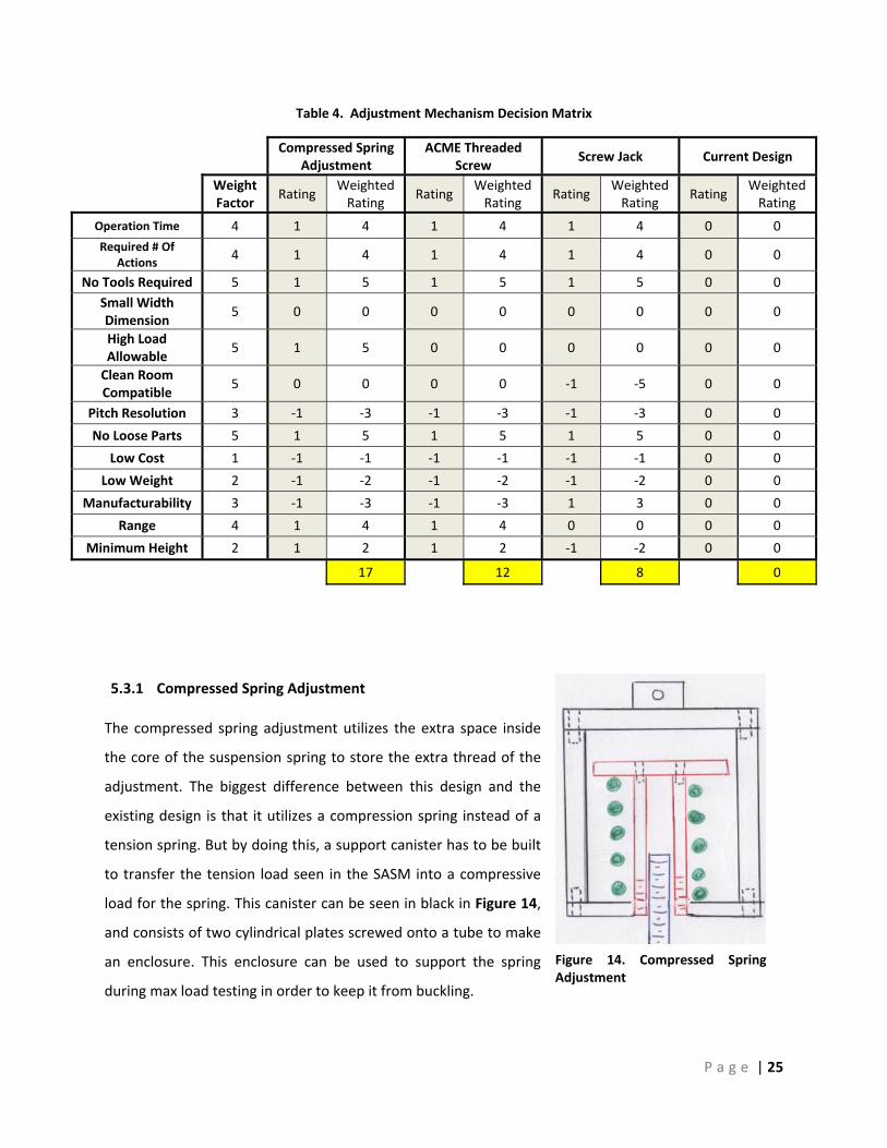
Table 4. Adjustment Mechanism Decision Matrix
Compressed Spring
Adjustment ACME Threaded
Screw Screw Jack Current Design
Weight Factor
Rating Weighted Rating
Rating Weighted Rating
Rating Weighted Rating
Rating Weighted Rating
Operation Time 4 1 4 1 4 1 4 0 0 Required # Of
Actions 4 1 4 1 4 1 4 0 0
No Tools Required 5 1 5 1 5 1 5 0 0 Small Width Dimension
5 0 0 0 0 0 0 0 0
High Load Allowable
5 1 5 0 0 0 0 0 0
Clean Room Compatible
5 0 0 0 0 ‐1 ‐5 0 0
Pitch Resolution 3 ‐1 ‐3 ‐1 ‐3 ‐1 ‐3 0 0
No Loose Parts 5 1 5 1 5 1 5 0 0
Low Cost 1 ‐1 ‐1 ‐1 ‐1 ‐1 ‐1 0 0
Low Weight 2 ‐1 ‐2 ‐1 ‐2 ‐1 ‐2 0 0
Manufacturability 3 ‐1 ‐3 ‐1 ‐3 1 3 0 0
Range 4 1 4 1 4 0 0 0 0
Minimum Height 2 1 2 1 2 ‐1 ‐2 0 0
17 12 8 0
5.3.1 Compressed Spring Adjustment
The compressed spring adjustment utilizes the extra space inside
the core of the suspension spring to store the extra thread of the
adjustment. The biggest difference between this design and the
existing design is that it utilizes a compression spring instead of a
tension spring. But by doing this, a support canister has to be built
to transfer the tension load seen in the SASM into a compressive
load for the spring. This canister can be seen in black in Figure 14,
and consists of two cylindrical plates screwed onto a tube to make
an enclosure. This enclosure can be used to support the spring
during max load testing in order to keep it from buckling.

P a g e | 26
The way adjustments are made with this concept is by simply rotating the threaded bar seen in blue in
Figure 14 such that it either rises into or retracts out of the threaded collar seen in red. By storing the
extra thread, it has the ability to condense the overall length of the design to make it more feasible for
the thermal testing room.
This concept scored the highest in the decision matrix because it was successful in either meeting or
improving on all the highest weighted specifications. It is capable of making fine adjustments without
the use of tools or loose parts, while efficiently utilizing space to make the overall SASM more feasible in
the thermal testing room. Even though the advantages outweigh the disadvantages, the manufacturing
process of this concept is going to be a lot more time consuming than the existing design.
5.3.2 ACME Threaded Screw with Collar
The second highest scoring adjustment mechanism is similar to the Compressed Spring Adjustment
because it also uses the empty space inside the core of the spring to store excess thread. The assembly
as seen in Figure 15 would attach the support spring to a custom collar. The collar is then used to adjust
the total length of the suspension mechanism while
simultaneously storing the unused thread within the core of the
support spring. In order to give the collar the freedom to rotate,
the top of the spring will be attached to a swivel and the
bottom of the thread will have its rotational freedom fixed.
This design’s width would be about the same as the spring in
the current suspension system, thus reducing interference
problems before deployment. Furthermore, storing the extra
thread inside of the spring has the benefit of significantly
reducing the minimum length of the suspension system
potentially mitigating the height constraint issue in the thermal
testing room. Finally, different lengths of rod could be used in
the same way that the current course adjustment bar functions
in the current suspension system.
Although the concept improves the existing design, this system
still has a number of disadvantages. The custom collar will need
to be manufactured. The custom collar will need to have a Figure 15. ACME Thread Sketch

P a g e | 27
Figure 16. Screw Jack
locking mechanism built into it as well as a groove so that it may attach to the spring. The other major
disadvantage is that large lengths of unused thread could potentially work their way in between the
coils and lock.
5.3.3 Screw Jack
Another method of making precise adjustments is by using a screw jack
similar to that seen in Figure 16. An exterior knob would be used to
move an internal rack up and down. This concept scored relatively high
in the decision matrix because it is able to make fine adjustments
without the use of tools or loose parts.
Although the concept improves the existing design, there are a few
disadvantages. First off, the manufactured component does not come
with an internal locking mechanism, which means that one would have
to be machined to prevent the jack from potentially elongating while
under load. Secondly, the internal gearbox may require grease, and as a
result, not be appropriate for the clean room.
5 . 4 C o n n e c t i o n Mec h a n i sm
The current method of using a clevis and u‐loop to connect the SASM to the solar arrays is time
consuming, requires an excessive amount of actions, and adds risk to the operation by the use of tools
and loose parts. All of the proposed designs were able to improve on the three previously mentioned
specifications, and showed positive improvements to the existing design overall. From the decision
matrix shown in Table 5, the carabiner was shown to best improve the existing design, while the rest of
the concepts scored relatively similarly, except for the Push Pin Lever, which was unable to show a
positive connection, unlike the other designs. The five concepts with the most potential are discussed
below.
To aid in the decision matrix utility, each specification has a weight factor which was determined by its
relative importance to the other specifications. No tools required and no loose parts both received a
weight factor of 5 since these two factors determine the success of the device. Eliminating loose parts
would greatly reduce the risk associated with installing the solar arrays as well as simplify the
installation process. High load allowable has a weight factor of 5 since the failure of SASM device would
lead to solar array damage and an unsafe work environment which are both unacceptable. The

P a g e | 28
operation time for connecting the panel and the number of actions required are two important
specifications that would greatly improve the device but do not determine the total success of the
project, so they received a weight factor of 4. The number of actions required is defined by the number
of steps needed to complete the operation. The current steps required are pulling the SASM down to
align with the clevis, placing the bolt through the holes, placing the nut on to the bolt and then
tightening the nut to total four actions required. The new design would like to implement a connection
procedure containing less than 3 actions. The remaining specifications are weighted relatively low
because they do not affect the overall success of the project. It is important to note that the positive
connection specification was defined by the number of senses used to verify connection such as visual
and auditory. The six concepts with the most potential are discussed below.
Table 5. Connection Mechanism Decision Matrix
Carabiner Mechanism
Pneumatic Connection Push to
Lock Swivel ‐ Nub Current Design
Weight Factor
Rating Weighted Rating
Rating Weighted Rating
Rating Weighted Rating
Rating Weighted Rating
Operation Time for Connecting
4 1 4 1 4 1 4 0 0
Number Of Actions Required
4 1 4 1 4 1 4 0 0
No Tools Required 5 1 5 1 5 1 5 0 0 Positive
Connection 3 0 0 1 3 0 0 0 0
High Load Allowable
5 0 0 0 0 0 0 0 0
No Loose Parts 5 1 5 1 5 1 5 0 0
Low Cost 1 1 1 ‐1 ‐1 ‐1 ‐1 0 0
Low Weight 2 0 0 0 0 0 0 0 0
Manufacturability 3 1 3 ‐1 ‐3 ‐1 ‐3 0 0 Excess Load Required
2 ‐1 ‐2 0 0 0 0 0 0
20 17 14 0

P a g e | 29
5.4.1 Carabiner
The carabiner is shown to improve on the existing design the most. This is because it can quickly and
positively connect an I‐Hook to the SASM without the use of tools or loose parts. It is also easy to
manufacture, since it can be purchased from a variety of manufacturers and requires no additional
machining in order to assemble it to the rest of the SASM. The only downside of the carabiner is that an
excessive amount of force is needed to pull down the spring in order to load the eye‐bolt into the
carabiner. A preliminary shear stress analysis of a carabiner under a 300 lb load can be seen in Appendix
F.
5.4.2 Pneumatic Hose Coupling
Another high scoring idea considers the use of a pneumatic air hose quick connect coupling. This device,
as shown in Figure 17, is extremely user friendly and easy to operate. The specific hose connect studied
has a push to connect feature. By simply placing the female end over the male clevis and pushing
together, the two pieces lock together. The quick connect works by the use of ball bearings that are
capable of locking into a groove on the male connection point. The ball bearings lock into place by the
outer sheath sliding down, trapping the ball bearings in with a smaller diameter ring inside the sheath.
To release the male terminal from the female, the operator pulls the sheath back until it disconnects.
Socket Stud U ‐ Loop Push Pin / Lever Current Design
Weight Factor
Rating Weighted Rating
Rating Weighted Rating
Rating Weighted Rating
Rating Weighted Rating
Operation Time for Connecting
4 1 4 1 4 1 4 0 0
Number Of Actions Required
4 1 4 1 4 1 4 0 0
No Tools Required 5 1 5 1 5 1 5 0 0
Positive Connection 3 0 0 0 0 ‐1 ‐3 0 0 High Load Allowable
5 0 0 0 0 0 0 0 0
No Loose Parts 5 1 5 1 5 1 5 0 0
Low Cost 1 ‐1 ‐1 ‐1 ‐1 ‐1 ‐1 0 0
Low Weight 2 0 0 0 0 ‐1 ‐2 0 0
Manufacturability 3 ‐1 ‐3 ‐1 ‐3 ‐1 ‐3 0 0 Excess Load Required
2 0 0 0 0 0 0 0 0
14 14 9 0

P a g e | 30
This device scored well in the decision matrix because it met all
the heaviest weighted specifications, such as the elimination of
tools and loose components, and it is the only concept that
improves the ability to show a positive connection due to its
combination of both visual and audible connection qualities. Also,
the general ease of use of this device is a huge positive for the
success of this concept.
Shear stress analysis and ball bearing contact farces of the
pneumatic hose coupling can be seen in Appendix H. Analysis on
the store bought pneumatic hose connection indicates extremely
high pressure points where the ball bearings contact the male
clevis that would cause failure at the surface. Since this would be
unacceptable, this concept is no longer being pursued.
5.4.3 Swivel Nub
Another promising concept is the “Swivel‐Nub”, as seen in
Figure 18. The panel connection piece is screwed into the
panels, and is held stationary in the vertical position. In order
to connect the SASM onto this connection piece, the swivel
component is brought down such that the extrusions of the
panel connection go through the slots in the swivel, and then
the swivel is rotated in the counter clockwise direction to lock
it in place. The gravitational force on the panels will keep the
nub of the panel connection piece inside the locking groove of
the swivel, until the swivel is manually pulled down and
twisted in the clockwise direction to disengage.
The Swivel Nub concept tied for third in the decision matrix
due to its ability to greatly improve all the heavily weighted
specifications, such as the elimination of tools and loose components, and the reduction of steps and
time to operate. Preliminary shear stress calculations of both the swivel and panel connection can be
seen in Appendix I.
Figure 18. Swivel Nub
Figure 17. Pneumatic Hose CouplingAssembly Cross Section

P a g e | 31
5.4.4 Socket Stud
Another quick connect concept that has potential is called the Socket Stud and is
shown in Figure 19. This concept uses a mechanism closely related to a bike
brake cable and how it is attached to the brake lever. At the end of a shaft
(what would be the cable on a brake cable) is a larger diameter cylinder that can
slide into a socket. When the shaft is raised, a ridge prevents the shaft from
sliding out of the socket. The shaft could then be locked into place by a safety
nut by threading it down to the body of the socket, as shown in Figure 19 by the
brass colored nut. The mechanism can be compact and can be designed to be
no more than 3/4ths in diameter. This design gives the user a sturdy, positive
connection that is easy to verify. Initial calculations which show that this design
is able to support the max load without yielding can be seen in Appendix J.
5.4.5 U Loop
Another potential concept uses two hooks to
close around an eyehook, and can be seen in
Figure 20. The hooks are pressed close to each
other and rotate about a pin. To close the
mechanism, there is a threaded sleeve that can
be screwed down over the top of the hooks,
locking them closed around the eyehook. This
solution requires no tools and has a positive
connection. Once the hooks are locked in place
and loaded, the force of the load will press the
hooks together, further locking them in place.
To disengage the hooks just unscrew the sleeve
and pull down on the suspension. The hooks
can be easily separated at this point and the
solar arrays are no longer attached.
The U‐Loop connection mechanism scored fairly well in the decision matrix because if its simplicity and
its strength. Analysis was done on the hooks and shoulder bolt using the Maximum Shear Stress Theory.
The minimum yield strength for the hooks to support a 300 lb weight is 16.4 kpsi, which can be greatly
Figure 19. Socket Stud
Figure 20. U‐Loop Concept Assembly
P a g e | 32
exceeded with most aluminum alloys. The minimum yield strength required for the pin 32.6 kpsi which
can be easily met by most carbon steels. The stress analysis calculations can be found in Appendix K.
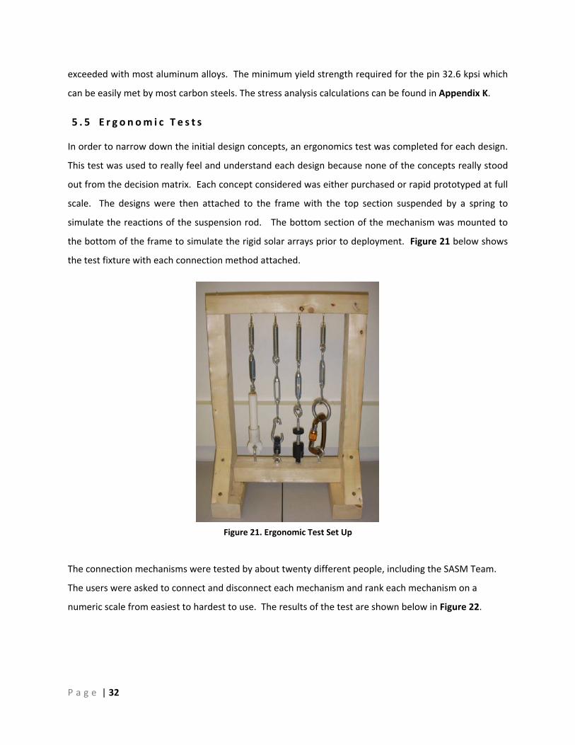
5 . 5 E r g o n om i c T e s t s
In order to narrow down the initial design concepts, an ergonomics test was completed for each design.
This test was used to really feel and understand each design because none of the concepts really stood
out from the decision matrix. Each concept considered was either purchased or rapid prototyped at full
scale. The designs were then attached to the frame with the top section suspended by a spring to
simulate the reactions of the suspension rod. The bottom section of the mechanism was mounted to
the bottom of the frame to simulate the rigid solar arrays prior to deployment. Figure 21 below shows
the test fixture with each connection method attached.
The connection mechanisms were tested by about twenty different people, including the SASM Team.
The users were asked to connect and disconnect each mechanism and rank each mechanism on a
numeric scale from easiest to hardest to use. The results of the test are shown below in Figure 22.
Figure 21. Ergonomic Test Set Up

P a g e | 33
The top designs were the Socket Stud and the Swivel Nub. Although the carabiner and U Loop were not
that far behind, the SASM Team felt that the auto‐locking features of the Swivel Nub and Socket Stud
really set them apart from the others. Due to the low cost of each of these mechanisms, the SASM team
manufactured both the Swivel Nub and Socket Stud and did strength and thermal testing on each design
before making a final decision on which design to utilize in the final assembly.
6 Manu f a c t u r i n g
6 . 1 Ma c h i n e d Sw i v e l Nub
Initial ergonomic testing and analysis narrowed down the final design to
two quick connect designs and a combined adjustment and spring
mechanism. Early issues with the manufacturing process of the swivel
nub urged the team to look into casting several of the components. The
manufacturing process of both the machined and casted swivel nub are
discussed below, followed by the manufacturing process of the socket
stud and adjustment mechanism.
The manufacturing of the finalized swivel nub seen in Figure 23 was more
time consuming than planned and the machining was not trivial. The
assembly consisted of five machined components, three being aluminum
and two being steel. All of the work was either done on a lathe or a mill,
and the total machining time is estimated to be around 4 ½ hours. The
Figure 22. Ergonomic Test Results
Figure 23. Swivel Nub Manufacturing

P a g e | 34
manufacturing process of the swivel top took about 2 hours itself, and the steps taken to manufacture
it are worth reviewing.
The first step in machining the Swivel Top was to drill the through hole for the ¼‐20 tap. This was done
by placing a one inch diameter stock aluminum rod on the lathe and drilling the minor diameter of
Ø.188” into it. After this, the inner cavity was bored out by first using a ½” mill to drill to the correct
length, and then using a boring bar to create the flat end condition of the inner cavity. This step
finalized the work on the lathe, and the un‐parted aluminum bar was brought over to the fourth axis
mill to do the rest of the cuts. It was important to not part the aluminum to length since a lot of extra
metal was needed to provide enough metal to clamp onto in the mill chuck.
The forth axis mill was set up such that the swivel top axis is horizontal to the table. The forth axis was
rotated for convenience to 0 degrees and a ¼ inch end mill was inserted into the mill chuck. In order to
do the vertical slot, the table is moved in the y‐direction such that it cuts in the same plane as the
swivel axis. Three passes were necessary in order to obtain the desired .27” gap. Once this gap was
complete, the forth axis was rotated 55° ccw while the end mill was kept at the correct depth in the y‐
direction. An additional three passes were necessary to complete the desired horizontal gap size. Once
completed, the forth axis was rotated back to zero degrees and the table was moved so that the end
mill was no longer touching the part. The forth axis was then rotated 180° and the same steps were
done to make the same slots on the opposite side. Once complete, the end mill was replaced with a
1/8” drill in order to make the press fit holes on the side. The manufactured swivel nub top can be seen
in Figure 24.
The only other issue the team ran into in the manufacturing of the swivel nub was the extensive
amount of time needed to machine steel. In order to mitigate thermal expansion problems of
Figure 24. Manufactured Swivel NubTop

P a g e | 35
dissimilar metals, the clevis and stress beam were both manufactured out of steel. Even though the
cuts necessary were very basic, in order to get a good finish, each pass on the lathe was taken very
slowly, and only a small amount of material was removed. The tools supplied to us at the Cal Poly
machine shop made cutting this harder metal a lot more difficult and resulted in an even longer
manufacturing time. The final assembly of the swivel nub can be seen in Figure 25.
6 . 2 C a s t e d Sw i v e l Nub
Due to the time intensive manufacturing process of the swivel top, the team looked into casting
several of the components through the manufacturing engineering department at Cal Poly for free. A
curved slot was inserted into the swivel top in order to aid the rotation of the stress beam as it locked
into place. This complex geometry was nearly impossible with the manual machining process, by could
be easily made with rapid prototype casting. The team also decided to cast the support bar as one
piece to eliminate any thermal expansion problems with the casting material. Figure 26 below shows
the curved slot design of the swivel top and the support bar.
Figure 25. Manufactured Swivel Assembly
Figure 26. Curved Slot and Cast Support Bar

P a g e | 36
The material provided by the manufacturing engineering department was ZA‐12, a zinc aluminum alloy
with a yield strength of 31 ksi. A finite element analysis was conducted on the part with this material
and minor dimensional changes were required to ensure the survival of the part. A gating system was
also designed into the part to allow the metal to flow into the part. Four or each part were rapid
prototyped and put into a pattern. Figure 27 below shows both patterns ready to be molded.
Figure 27. Swivel and Support Patterns
A plaster mold was made from these patterns and allowed to settle over night. The molds were cured
in a furnace and the plastic prototypes were melted out. Once cured, the metal was poured into the
mold and allowed to cool. The parts were broken out of the plaster and cut off of the pattern. The
finished parts are shown in Figure 28 below, but the gating system still needs to be removed and the
edges need to be ground down.
Figure 28. Casted Swivel Nub

P a g e | 37
6 . 3 S o c k e t S t u d
The socket stud was the second quick connect design chosen to be manufactured for a final design. The
SASM Team chose to manufacture the socket stud at the Cal Poly Machine shop in order to get a quick
turnaround time at an inexpensive cost and to gain machining and manufacturing experience.
The Socket Stud and the Safety Collar were the only custom components which needed to be
manufactured for this design since all other components are off the shelf. Aluminum was chosen as the
manufacturing material due to its easy machining properties. The intricate shape of the socket proved
to be difficult to machine, however, over time the procedure became more trivial. There were two
separate designs that were manufactured, the first of which can be seen in Figure 29. The final socket
stud prototype can be seen in Figure 30 and is close to identical to the first prototype except for minor
changes to include a stainless steel shoulder bolt at the connecting point. and the design of the
complete assembly with the Safety Collar is presented in Figure 30.
The socket stud manufacturing process started with 1” bar stock in the lathe. The end was faced and
the outer diameter was turned down to .75”. Next a .25” through hole was drilled and a .422” hole
was drilled to a depth of 1.5”. Care had to be taken on this process since the socket cap screw head sits
on this surface. Once the socket was parted and faced the socket hole and slot were milled carefully
Figure 29. First Socket Stud prototype
Figure 30. Final Socket Stud prototype
P a g e | 38
using a .25” end mill. The .125 rounds were milled with a smaller bit and then the part was
repositioned to drill the shoulder bolt profile. Lastly, the part was deburred and tapped. The safety
collar was simple to manufacture and involved turning the outside, drilling a .25” diameter, boring the
inside and parting the Safety Collar off.
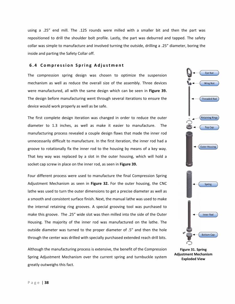
6 . 4 C omp r e s s i o n S p r i n g Ad j u s tm e n t
The compression spring design was chosen to optimize the suspension
mechanism as well as reduce the overall size of the assembly. Three devices
were manufactured, all with the same design which can be seen in Figure 39.
The design before manufacturing went through several iterations to ensure the
device would work properly as well as be safe.
The first complete design iteration was changed in order to reduce the outer
diameter to 1.3 inches, as well as make it easier to manufacture. The
manufacturing process revealed a couple design flaws that made the inner rod
unnecessarily difficult to manufacture. In the first iteration, the inner rod had a
groove to rotationally fix the inner rod to the housing by means of a key way.
That key way was replaced by a slot in the outer housing, which will hold a
socket cap screw in place on the inner rod, as seen in Figure 39.
Four different process were used to manufacture the final Compression Spring
Adjustment Mechanism as seen in Figure 32. For the outer housing, the CNC
lathe was used to turn the outer dimensions to get a precise diameter as well as
a smooth and consistent surface finish. Next, the manual lathe was used to make
the internal retaining ring grooves. A special grooving tool was purchased to
make this groove. The .25” wide slot was then milled into the side of the Outer
Housing. The majority of the inner rod was manufactured on the lathe. The
outside diameter was turned to the proper diameter of .5” and then the hole
through the center was drilled with specially purchased extended reach drill bits.
Although the manufacturing process is extensive, the benefit of the Compression
Spring Adjustment Mechanism over the current spring and turnbuckle system
greatly outweighs this fact.
Figure 31. Spring Adjustment Mechanism
Exploded View

P a g e | 39
7 De s i g n Ve r i f i c a t i o n ( Te s t i n g )
7 . 1 App r o a c h a n d Me t h o d o l o g y
The first step in verifying the functionality of a design is to highlight all the high risk failure modes. Once
the high risk areas are predicted, tests can be completed to verify the severity, occurrence or detection
rating of a particular failure mode. Depending on the results, a mitigation plan can be completed to
reduce the severity and occurrence, or to increase the detection rate of the failure. A Design Failure
Mode and Effects Analysis was completed for the each subsystem including the force gauge, adjustment
mechanism, and quick connect. Suspect high risk failures can be seen in Appendix M.
For each sub‐system, failure modes were established and were rated by severity, occurrence and
detection rating. The severity ratings ranged from 10, meaning the failure has the potential to
permanently damage the customer or the panels, all the way down to 1, meaning that the failure would
not even be noticeable and would have no affect on the customer or the panels. The occurrence rating
ranged from 10, meaning failure is almost inevitable, to 1, meaning the failure is extremely unlikely. The
last set of predictions deals with the current controls of how to mitigate the failure. All of the
preventative actions which can be made by the user or the team were outlined, along with any
detection mechanisms built into the design. With both of these measurements accounted for, the
detection rating was predicted, and they ranged from 1, meaning that the defect is obvious and will
certainly be detected, to 10, meaning the device is not able to be inspected for the particular failure
mode. In order to quantify the risk of each failure mode, the severity, occurrence and detection ratings
were multiplied together to yield a level of risk. We only considered making tests for levels of risk above
100 and a list of these tests can be seen in Appendix N.
Figure 32. Manufacturing process of the Compression Spring Adjustment Mechanism

P a g e | 40
7 . 2 T e s t De s c r i p t i o n s a n d R e s u l t s
The first test is the unthreading test. This test is meant to measure how much the adjustment
mechanism unthreads due to a 300 pound load. This test was done by loading the adjustment in
tension in the Instron machine and watching to see if the outer housing rotated due to the applied load.
The test showed that the adjustment did not unthread during the loading and all expansion was due to
the strain placed upon the system.
The second test is the Thermal cooling test, and was completed on the swivel nub, socket stud and
adjustment mechanism. This test proves that the system can go through a full cooling cycle without
sustaining any major damage. The parts were cooled in a sealed foam container with dry ice while being
monitored by thermo, and can be seen in Figure 33. It took approximately 20 minutes for the parts to
reach thermal equilibrium of about ‐70°C within the foam container. The parts were then taken out and
allowed to warm back up to room temperature. After the parts had warmed back up they were
inspected. This was conducted by visual inspection of the parts using a magnifying glass. No cracks or
signs of wear were discovered on the parts that had been cooled and reheated.
The third test was to check if the severe temperature drop would cause the parts to seize and was done
in conjunction with the second test. After all the parts were cooled and reheated from the second test,
the team verified that all of the parts were able to either disconnect or adjust properly.
The fourth and fifth tests were conducted by putting the swivel nub, socket stud and adjustment
mechanism in tension to 300 pounds. The tensile machine was set to stretch the quick connects at a rate
of .01 in/min in order to test the quasi‐static properties. The tests looked to see if the components
Figure 33. Cooling of the Socket Stud

P a g e | 41
experienced yielding or surpassed their ultimate strength for an applied load of 300lbs. The test was
conducted in the Instron machine while the parts were at room temperature and then the parts were
cooled to ‐70°C in the foam test chamber loaded to 300 pounds again. The test set up for both the
cryogenic and room temperature tensile testing can be seen in Figure 34 and Figure 35. The internal
temperature was monitored with thermocouples and a summary of test data can be found in Table 6.
None of the parts failed during loading or showed signs of yielding.
Table 6. Room Temperature and Cryogenic Test Data
Room Temperature Cryogenic Test
Part Max Load Delta L Max Load Delta L Initial Temp Final Temp
[lbs] [in] [lbs] [in] [Celsius] [Celsius] Swivel Nub 300 0.031 300 0.039 ‐68.3 ‐62.4
Extension Mechanism Note A 3 390 2.663 ‐69.8 ‐60 Socket Stud 300 0.048 311 0.041 ‐68.7 ‐70.6
Cast Swivel Nub 300 0.022 305 0.015 ‐66 Note B
Cast S. N. to Failure 1038 0.51 Note A: machine Pulled to a force greater then 1000 lbs
Note B: Thermo Couple Broke and no more data could be taken
Figure 35. Cryogenic Tensile Testing Figure 34. Room Temperature Tensile Testing

P a g e | 42
The previous five tests proved the functionality of both the quick connect designs and the adjustment
mechanism, but did not test the ergonomics. This was done in tests 6 and 7, and was used to make the
final decision on which quick connect device to use in the final assembly. Both the socket stud and
swivel nub were placed in series with the adjustment mechanism, and the team members took turns
connecting and disconnecting the mechanisms. Data was taken on how much time it took to make the
connections and adjustments to a load of 30 pounds. It was found that both connectors were able to
connect within two seconds, which is well below the accepted value of 10 seconds. The adjustment time
was found to be less than 10 seconds, which is well below the accepted value of 30 seconds. Since both
quick connect designs tested similarly across the field, the design with the least amount of components
and the easiest manufacturing was chosen to be in the final design, which is the Socket Stud.
In order to verify that the socket stud was definitely operated in the elastic region, strain gauges were
attached to it and stress and strain values were recorded up to a load of 2400 pounds. As seen in Figure
36 the stress‐strain correlation is linear up to a stress of about 10,000 psi. This confirms that the socket
stud will not plastically yield at 300 pounds, which correlates to a stress of 1345 psi. One concern about
this analysis is that the experimental elastic modulus of 40 million Psi is about four times higher than the
theoretically accepted value of 10 million Psi. One explanation for this difference is that the strain
gauges were placed very close to the edge of the slot and could have been picking up strain in a stress
concentrated area, as seen in Figure 37. In addition, due to the geometry of the Socket Stud, the
location picked for the strain gauges was also in bending, which would increase the elastic modulus.
Figure 36. Socket Stud Stress vs. Strain Graph
Figure 37. Strain Testing on Socket Stud

P a g e | 43
8 F i n a l De s i g n
8 . 1 A s s emb l y De s c r i p t i o n
The final assembly shown in Figure 38 consists of the current
analogue force gauge, the current large adjustment bar, a
compressed spring adjustment, and the socket stud quick
connect. It provides a quick way for technicians to reliably
connect and disconnect solar panel arrays for testing without
the use of tools or loose parts. The analogue force gauge was
chosen due to its ease of use, availability and reliability in both
the thermal testing environment and standard clean room. Both
alternative solutions failed to improve the existing design, and
the load cell concept in particular would’ve added risk and
complications to the overall system by introducing electrical
components into an untested environment. Two shackles in
series will attach the analogue force gauge to the large
adjustment bar. Another shackle will be used to connect the
large adjustment bar to the compressed spring adjustment
mechanism. The compressed spring adjustment was chosen
because it combines the minor adjustments along with the
compression spring into one sub‐assembly. It provides a reliable
solution for both the standard and cryogenic testing rooms and
utilizes basic components which were relatively easy to
manufacture. The adjustment mechanism will be connected to
the socket stud by a bearing swivel eye clevis. Even though the
socket stud and swivel nub tested similarly, the socket’s stud
ease of manufacturing and reduced number of components
made it the more appealing solution. A complete detailed
drawing of the assembly can be seen in Appendix C.
A summary of the specifications and if they were met by the final design can be seen in Table 7. The
final design met all of the requirements except for being able to connect under a load. The adjustment
Figure 38. SASM Final Assembly

P a g e | 44
mechanism will need to be used to displace the Socket Stud low enough to engage the socket cap screw.
Once connected, the adjustment can be raised to displace the correct load.
Table 7. Final Specification Table
Overall System Specifications Spec
# Parameter Description Requirement or Target (units) Tolerance Verified
1 Number of Tools Required 0 Max Yes
2 Quantity of Loose parts 0 Max Yes
3 # of Actions Required to Operate 3 actions Max Yes
4 Visibility of Parts All (High) N/A Yes 5 Width Dimensions 1.3 Inches Max Yes 6 Load Allowable 100 lb +200lb Yes 7 Cost $8,000 Max Yes: $2,900 8 Weight 8 lb Max Yes 9 Temperature Range -80 C to 50 C Range Yes 10 Clean Room Compatible 0 Intrusive Elements Max Yes
Specific Adjustment Mechanism Specifications Spec
# Parameter Description Requirement or Target (units) Tolerance Verified
13 Operation Time of Adjustments 30 Seconds Max Yes: <10 seconds
14 Pitch Resolution 1/14" +/-1/28 Yes
Specific Quick Connect Specifications Spec
# Parameter Description Requirement or Target (units) Tolerance Verified
15 Operation Time for Connecting 5 seconds Max Yes: Under 2 seconds
16 Unload / Loading Deflection 3/4 inch +/- 1/4" No: Adjustment required for
connection
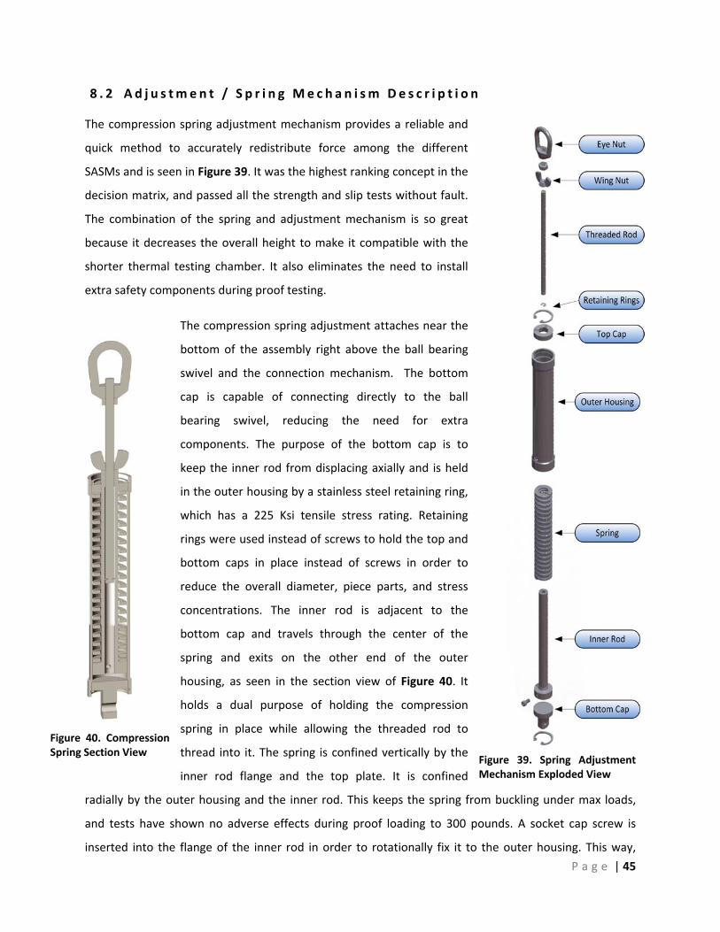
P a g e | 45
8 . 2 Ad j u s tm e n t / S p r i n g Me c h a n i sm De s c r i p t i o n
The compression spring adjustment mechanism provides a reliable and
quick method to accurately redistribute force among the different
SASMs and is seen in Figure 39. It was the highest ranking concept in the
decision matrix, and passed all the strength and slip tests without fault.
The combination of the spring and adjustment mechanism is so great
because it decreases the overall height to make it compatible with the
shorter thermal testing chamber. It also eliminates the need to install
extra safety components during proof testing.
The compression spring adjustment attaches near the
bottom of the assembly right above the ball bearing
swivel and the connection mechanism. The bottom
cap is capable of connecting directly to the ball
bearing swivel, reducing the need for extra
components. The purpose of the bottom cap is to
keep the inner rod from displacing axially and is held
in the outer housing by a stainless steel retaining ring,
which has a 225 Ksi tensile stress rating. Retaining
rings were used instead of screws to hold the top and
bottom caps in place instead of screws in order to
reduce the overall diameter, piece parts, and stress
concentrations. The inner rod is adjacent to the
bottom cap and travels through the center of the
spring and exits on the other end of the outer
housing, as seen in the section view of Figure 40. It
holds a dual purpose of holding the compression
spring in place while allowing the threaded rod to
thread into it. The spring is confined vertically by the
inner rod flange and the top plate. It is confined
radially by the outer housing and the inner rod. This keeps the spring from buckling under max loads,
and tests have shown no adverse effects during proof loading to 300 pounds. A socket cap screw is
inserted into the flange of the inner rod in order to rotationally fix it to the outer housing. This way,
Figure 39. Spring Adjustment Mechanism Exploded View
Figure 40. CompressionSpring Section View

P a g e | 46
when the outer housing is spun, the inner rod rotates with it, allowing the threaded rod to thread into
or out of the inner rod. This movement will be simple for an operator to perform since he or she does
not have to loosen two sides of a turnbuckle before adjusting the height. Since mechanical failure in any
section of the SASM is unacceptable, adjustment mechanism was designed robustly and drawings can be
seen in Appendix D.
8 . 3 S o c k e t S t u d De s c r i p t i o n
The Socket Stud provides a secure connection between the
SASM and the solar arrays. It is simple to operate, easy to
manufacture, and requires no tools to operate. The design
includes only two manufactured components, the socket stud
and the safety, and five off the shelf parts. The complete
assembly can be seen in Figure 41 and a detailed drawing can
be found in Appendix E. The socket cap screw replaces the
current clevis, and is threaded into the solar array’s ¼‐28
embedded hole while the socket stud is attached to the bottom
end of the SASM. In order to connect the socket stud to the
socket cap screw, the operator pulls down on the socket stud
and displaces the safety. The slot in the socket stud is aligned
with the head of the socket cap screw and is slid under the head
of the screw to connect. The operator pulls down on the socket to align the socket opening with the
head of the screw and slides it in. The screw head is kept from easily sliding out by sitting in a .1 inch
deep groove. Once the bolt is in place, the safety collar displaces upward due to the spring activation
and it encompasses the opening in the socket stud in order to assure no accidental disconnects.
8 . 4 F u t u r e B u i l d C o n s i d e r a t i o n s
Future builds of the SASM should be made out of steel instead of aluminum. Even though the
manufactured aluminum parts passed all of the strength requirements, they were easily marred during
tests and showed signs of wear after only a few cycles. Also, by making everything out of steel, it would
make the assembly expand and contract homogenously. In addition, it is important to note that any
socket head cap screw length can be used in order to incorporate the depth of the alignment cube used
to keep the solar arrays locked when not being deployed.
Figure 41. Socket Stud Assembly

P a g e | 47
8 . 5 An a l y s i s R e s u l t s
As outlined earlier, the main operation of the Solar Array Suspension Mechanism is to support the
weight of solar panels in a quasi‐static environment. The typical load seen by the Suspension Mechanism
is around 100lb. A factor of safety of 3 was introduced to the load in order to account for an unexpected
increase or misuse of the device. This load of 300lbs was then used for all analysis and factors of safety
are derived for this load.
Initial analysis was done using classical mechanics of materials. Using the typical published yield
strengths for Aluminum in Shigliey’s Mechanical Engineering Design 8th Edition, geometric properties like
wall thicknesses and part sizes were derived. These induced stresses were based on the 300lb load
criteria. Hand calculations were completed on all of the quick connect concepts including the Carabiner,
Pneumatic, Swivel Nub, Socket Stud and U‐Loop and can be seen in Appendix F through Appendix K.
Using these methods the original size of the components was determined and used to generate the
initial solid models.
In order to verify these initial designs Finite Element Analysis was used on the models chosen to be
manufactured, including the Swivel Nub and Socket Stud. The FEA was done using linear static elements.
Each component was imported from solid works individually and analyzed using ABAQUS. Each
component of each sub assembly was pinned at the locations where is would be in contact with the
component located above it. For the components that interfaced with threads the embed criteria was
used as a boundary condition for the surface area that would be in contact with the threads. The load
was always applied to the lowest area of contact as a resulting pressure.
To gauge the accuracy of the FEA a mesh convergence for a critical point was preformed. The mesh
convergence was done by relating the stress at that particular node to the number of degrees of
freedom used in the analysis. When the stress did not change by a significant amount (ie 5%) that size
element and mesh was used for the analysis of the whole part. The mesh convergence and FEA models
can be found for the Swivel Nub in Appendix I and the Socket Stud in Appendix J. The node with the
maximum stress was then compared to the yield strength of the material that was used to machine it.
The factor of safety for each part is defined as the maximum stress from the FEA divided by the yield
strength for that material. A simple force over area stress calculation was completed for the outer
housing of the adjustment mechanism at the thinnest area where the retaining ring sits. An FEA model
was quickly completed to verify these simple hand calculations, and the results correlated nicely. A
summary of these FOS can be found in Table 8.

P a g e | 48
Table 8. Factor of Safety for Each Component
Maximum Stress (Kpsi)
Yield Strength (Kpsi)
FOS for 300lb Load
Swivel Nub 33.2 42
(Aluminum)
1.27 Socket Stud 8 5.2 Adjustment 1.3 30
In order to check the accuracy of the FEA analysis a model of the Cast Swivel Nub was used to predict a
failure region and failure mode at ultimate strength. The Cast Swivel Nub was brought to failure and
then compared to the FEA analysis in order to verify the model. Figure 42 shows the point of failure of
the Cast Swivel Nub.
In addition to doing a Finite Element Analysis, the team also completed a Coefficient of Thermal
Expansion analysis on the final assembly. The goal was to quantify the maximum deflection due to
thermal strain of the Adjustment Mechanism and Socket Stud when placed in series. In order to simplify
the calculations, and to have the analysis valid for future builds, the material used in the analysis was
steel. Steel has a coefficient of thermal expansion of Fin
in°•
μ6.9 . The temperature range used in the
calculations was from 25°C to ‐80°C. The complete analysis can be seen in Appendix L, and the results
showed a change in length of merely ‐.032 inches. If it can be assumed that all of the Solar Array
Suspension Mechanisms are in parallel, and are of the same material, then they should all uniformly
contract. This means that no stress concentrations due to thermal contraction should form at the hinges
of the solar arrays.
Failure Point
Figure 42. Failure Point Compared to FEA

P a g e | 49
8 . 6 C o s t B r e a k d own
Each SASM assembly as defined by the design specifications had a maximum cost of $8000. The SASM
team successfully designed a robust and reliable system for significantly less with an approximate total
of $2900 as shown in Table 9. This cost is based on our final design which includes the current analogue
ring force gauge, current square bar long adjustment, Compression Spring Adjustment Mechanism, and
Socket Stud quick connect. The exact cost of the analogue ring force gauge was unknown to the team so
it was estimated to be $1500. The cost of the machined components are highlighted in blue on Table 9
and was estimated based on the time it took the SASM Team to machine each component and the
hourly rates of a local machine shop, Snider Precision, plus the cost of material. It should be noted that
the cost of manufacturing these devices will vary depending on the manufacturer as well as the number
of devices to be made.

P a g e | 50
Table 9. Cost estimate for one SASM device
Sub Assembly Component SASM Machine Time [Hours]
Estimated Cost [$]
Force Gauge Analogue Ring Gauge ‐ 1500
Long Adjustment Square Bar ‐ 50
Compression Spring Adjustment Mechanism
Outer housing 1.5 135 Inner rod 1.5 135 Top cap .25 25 Bottom cap .75 75 2 X Internal retaining ring ‐ 4 Chrome‐silicon steel die spring ‐ 8 Socket cap screw ‐ 1 Threaded rod .25 30 Hex nut ‐ 1 SS oval eye nut ‐ 16 SS E‐style retaining ring ‐ 1 Wing nut ‐ 2
Compression Spring Adjustment Mechanism Total: 4.0 370
Socket Stud
Socket Stud 2 165 Safety Collar .5 50 Socket Cap Screw ‐ 1 Hex Nut ¼‐28 ‐ 1 Steel Compression Spring ‐ 1 Shoulder Screw ‐ 3 Hex Nut ¼‐20 ‐ 1
Socket Stud Total: 2.5 215
Miscellaneous Ball Bearing Swivel ‐ 70 4 X D‐Shackle ‐ 40
Total Cost: 2900
The SASM team was budgeted by ATK $2,500 to complete this design challenge. The team was well
under the designated budget and spent approximately $740 for raw material, off the shelf parts, tooling,
and testing and display fixtures. The expenditure breakdown can be seen in Appendix O and includes
prices of raw material, hardware and an estimate of shipping and fixture costs.

P a g e | 51
9 C o n c l u s i o n The final design presented by the Solar Suspension Technologies team surpassed the design
requirements presented by ATK. The proposed SASM has no removable parts, requires no tools to
operate and can easily adjust its length. This final assembly includes the analog force gage that is
currently used by ATK, a compression spring adjustment mechanism, bars for long adjustments and a
Socket Stud quick connection device. The mechanism will also operate in the required cryogenic
temperatures without part fatigue or failure. The estimated total cost for the proposed SASM is $2900,
which is significantly less than the specified total cost of $8000. The team is satisfied with the results of
the design and look forward to the implementation of the SASM at ATK Space.

P a g e | 52
I n d e x t o Ap p e n d i c e s
Appendix A : Quality Function Deployment ....................................................................................................... 53
Appendix B : Gantt Chart ................................................................................................................................... 54
Appendix C : SASM Final Assembly Drawing ...................................................................................................... 55
Appendix D : Compression Spring Adjustment Drawing ..................................................................................... 56
Appendix E : Socket Stud Assembly Drawing ..................................................................................................... 58
Appendix F : Swivel Nub Assembly Drawing ...................................................................................................... 59
Appendix G : Carabiner Stress Analysis .............................................................................................................. 61
Appendix H : Pneumatic Stress Analysis ............................................................................................................ 62
Appendix I : Swivel Nub Stress Analysis ............................................................................................................. 64
Appendix J : Socket Stud Stress Analysis ............................................................................................................ 69
Appendix K : U‐Loop Stress Analysis .................................................................................................................. 72
Appendix L : Coefficient of Thermal Expansion Analysis ..................................................................................... 74
Appendix M : Design Failure Modes Effect Analysis ........................................................................................... 75
Appendix N : Design Verification Plan & Report ................................................................................................. 76
Appendix O : Expenditure Report ...................................................................................................................... 77

P a g e | 53
Appendix A: Qual i ty Funct ion Deployment

P a g e | 54
Appendix B: Gantt Chart
:

P a g e | 55
Appendix C: SASM F ina l Assembly Drawing

P a g e | 56
Appendix D: Compress ion Spr ing Adjustment Drawing

P a g e | 57

P a g e | 58
Appendix E: Socket Stud Assembly Drawing

P a g e | 59
Appendix F : Swive l Nub Assembly Drawing

P a g e | 60

P a g e | 61
Appendix G: Carabiner Stress Analys i s
Given:
P=300lbs
d=0.287in (TYP)
D=1.2in (TYP)
Solution:

P a g e | 62
Appendix H: Pneumat ic Stress Analys i s
Free body diagram for the analysis of the Pneumatic device
Dimensions and properties F = 100 [lb f ] Sf = 30000 [psi]
d1 = 0.1365 [in]
d2 = 1 x 10 9 [in]
E1 = 3 x 10 7 [psi]
E2 = E1 v1 = 0.292
v2 = v1 z = 0.00001

P a g e | 63
Stress analysis equations using Engineering Equation Solver (EES)
a = 3 · F
8 ·
1 – v12
E1 +
1 – v22
E2
1d1
+ 1d2
( 1 / 3 )
pmax = 3 · F
2 · π · a 2
σ1 = – pmax · 1 – za
· arctan1za
· ( 1 + v1 ) – 1
2 · 1 + z 2
a 2
σ2 = σ1
σ3 = – pmax
1 + z 2
a 2
Sy = ( σ1 – σ2 ) 2 + ( σ2 – σ3 ) 2 + ( σ3 – σ1 ) 2
2
( 1 / 2 )
The following are the solutions to the above equations. Notice how the factor of safety (FS) is only .137. Since it is below 1, these calculations indicate it would fail under these stresses.

P a g e | 64
Appendix I : Swive l Nub Stress Analys i s
Swivel Top Hand Calculations
Material Properties of 2011 Aluminum:
KpsiS
KpsiS
u
y
0.68
0.47
=
=
( ) 4433
10721.212
25.209.12
inininbhI x−×===
inlbinlbFDM ⋅=×== 5.1309.150
( )( ) Kpsiin
ininlbI
Mc 2.610721.2
125.5.1344 =
×⋅
== −σ
Kpsiinin
lbAP 87.2
25.209.150
=×
==τ
nS y
Max 2231 ≥
−=
σστ
nKpsiKpsiKpsi
Max 247
2)12.1(32.7≥
−−=τ 5.5=n
5
5
‐5
‐5 )(Kpsiσ
)(Kpsiτ
Kpsi32.71 =σKpsi12.13 −=σ
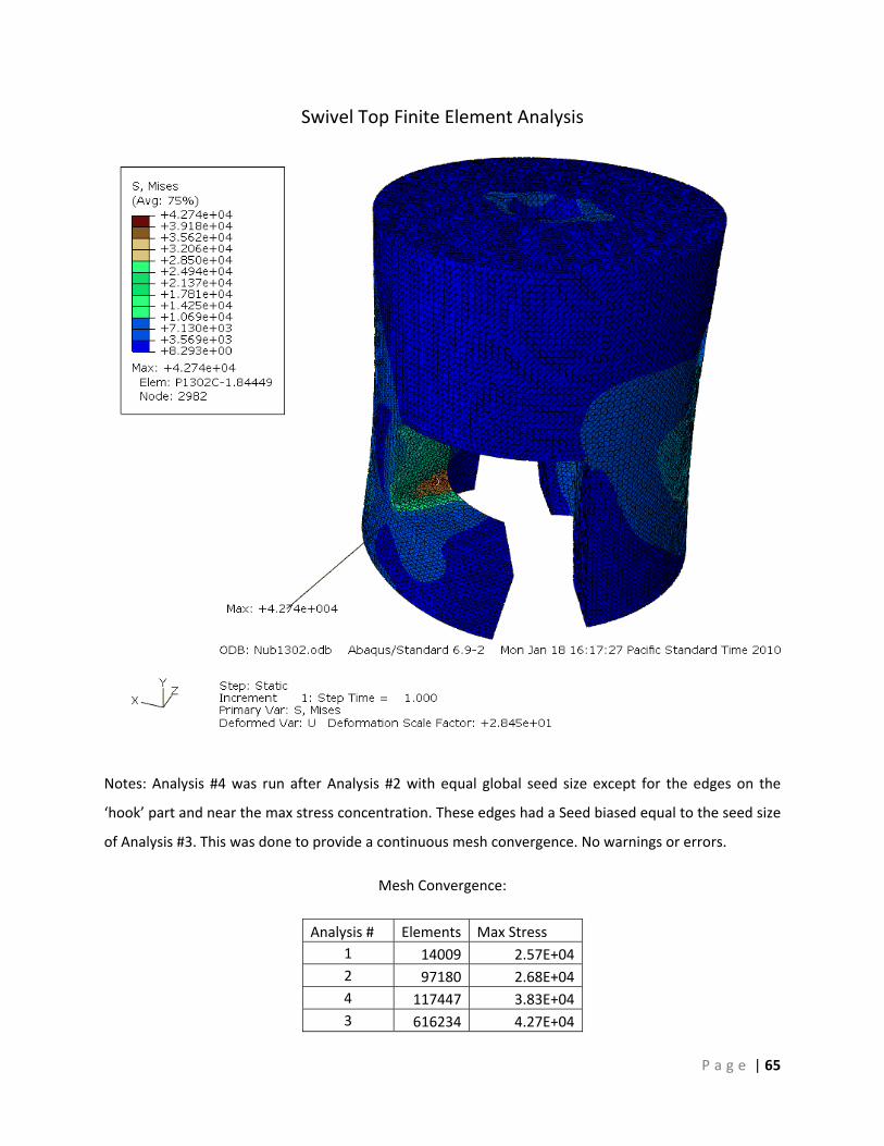
P a g e | 65
Swivel Top Finite Element Analysis
Notes: Analysis #4 was run after Analysis #2 with equal global seed size except for the edges on the
‘hook’ part and near the max stress concentration. These edges had a Seed biased equal to the seed size
of Analysis #3. This was done to provide a continuous mesh convergence. No warnings or errors.
Mesh Convergence:
Analysis # Elements Max Stress 1 14009 2.57E+042 97180 2.68E+044 117447 3.83E+043 616234 4.27E+04

P a g e | 66
Stress Beam Hand Calculations
Material Properties of 2024
Aluminum:
KpsiS
KpsiS
u
y
0.47
5.24
=
=
( ) 4433
10627.112
25.125.12
inxininbhI x−===
inlbinlbFDM ⋅=×== 5.17117.150
( )( ) Kpsiin
ininlbI
Mc 4.1310627.1
117.5.1744 =
×⋅
== −σ
Kpsiinin
lbAP 8.4
25.125.150
=×
==τ
nS y
Max 2231 ≥
−=
σστ
nKpsiKpsiKpsi
Max 247
2)5.1(9.14≥
−−=τ 9.2=n
5
)(Kpsiσ
)(Kpsiτ
5‐5
‐5
Kpsi9.141 =σKpsi5.13 −=σ

P a g e | 67
Stress Beam Finite Element Analysis
Notes: Shown above is a view of the cross section at the edge of a boundary condition. Quadratic‐
quadrilateral elements distorted unrealistically around the boundary condition, so all the analysis was
done with linear‐quadrilateral elements. Further analysis was restricted by computing power. No
warnings or errors.
Mesh Convergence:
Analysis # Elements Max Stress 1 1950 1.87E+04 2 14480 2.37E+04 3 124000 3.90E+04

P a g e | 68
Clevis Finite Element Analysis
Notes: Consistent results with no warning or errors. No warnings or errors.
Mesh convergence:
Analysis # Elements Max Stress 1 27208 1.11E+04 2 138169 1.42E+04

P a g e | 69
Appendix J : Socket Stud Stress Analys i s
Free Body Diagram for the analysis of the Socket Stud
Equations to solve stresses in socket stud using Engineering Equation Solver (EES) Dimensions and Properties F = 300 [lb f ] L1 = 0.125 [in]
H = 0.15 [in]
R1 = 0.21 [in]
E1 = 1.04 x 10 7 [psi]
Sy = 24500 [psi]
D1 = R1 · 2 [in]
D2 = 0.75 [in]
Stress Analysis Equations θ2
= arcsinL1
R1
Larc = π · D1 · 1 – θ
360
A1 = Larc · H
τ = FA1

P a g e | 70
A2 = 0.5 · D2
2
4 · π –
D12
4 · π
σ = FA2
σ1 = σ2
+ σ2
2
+ τ2
( 1 / 2 )
σ2 = σ2
– σ2
2
+ τ2
( 1 / 2 )
τmax = σ1 – σ2
2
σv on,mises = ( σ2 + 3 · τ
2 )0.5
SFv on,mises = Sy
τ
The following are solutions for the above equations. Notice a safety factor of 12.88

P a g e | 71
Notes: Max stress occurred at the point of maximum discontinuities with a value of 8.036E3 [psi]. Linear
Tetrahedral elements where used for the analysis. There were 10 distorted whose aspect ratio exceeded
0.1. These elements where not located near critical points. Mesh Convergence Shows that there is a 20%
change in max stress from analysis 2 to 3.
Mesh Convergence:
Analysis #
Degrees of FreedomMax Stress
1 3528 6.39E+03 2 18930 6.87E+03 3 122475 8.04E+03

P a g e | 72
Appendix K: U ‐Loop Stress Analys i s
EES Calculations

P a g e | 73

P a g e | 74
0
01
LLL
T−
=ε
ininininL 3845.183845.18)0017472.(1 +×−=
Appendix L : Coef f i c ient of Thermal Expans ion Analys i s
The goal of this analysis is to quantify the change in length of the adjustment mechanism and socket
stud when placed in series over an extreme temperature difference.
Given:
Coefficient of Thermal Expansion for Steel:
Initial Temperature:
Final Temperature:
Active Length of Compression Spring and Socket Stud:
Thermal Strain Analysis:
Finin°•
=μα 6.9
FCT °°= 70~251
FCT °−°−= 112~802
( )FFFin
inT °−°−×
°•= 701126.9 με
inin
T 0017472.−=ε
inL 385.180 =
inL 35239.181 =
incesL 032.−=Δ
TT Δ= αε

P a g e | 75
Appendix M: Des ign Fa i lure Modes Ef fect Analys i s Functio
n
Failure M
ode
Potential Effects of
Failure
Severity
Cause of Failure
Occuren
ce
Preven
tion
Detectio
n
Detectio
n Ra
ting
TOTA
L
Failure Modes for Adjustment Mechanism
Adjust Length
Unthreading
Improper Length ‐ Point
Loads 6
High weight overcomes friction
in thread 4 Locking Mechanism
Manual Inspection
6 144
Damage to Panels
10 Complete
Unthreading 2 Thread stop at end
Visual Inspection
3 60
Improper setup
Damage to Panels
10 Human Error 3 User Manual Visual and Manual
3 90
Support
Thermal Expansion
Improper Length
6 Material Properties 2 Protype Builds Measurement 7 84
Fracture, Failure 10 Rapid Cooling 4 Maximum Cooling
Rate Visual
Inspection 3 120
Yielding Payload Damage
10 Overloading 1 Correct Sizing Spring at max
load 6 60
Failure Modes for Quick Connect
Connection
No Connection
Retry Connection
3 Seizing 5 Maintenance Does not Connect
6 90
False Positive Connection
10 Human Error 3 Use safety mechanism
Safety not engaged
3 90
10 Component Damage
1 Safe Handling Visible Damage
2 20
Failure to Disconnect
Disassemble 6 Seizing 5 Maintenance Does not Disconnect
6 180
Support Yielding Payload Damage
10 Overloading 1 Correct Sizing /
Material Selection Spring Failure 3 30
10 Extreme
Temperatures 2
Insulation / Material Selection
Visual Inspection
3 60
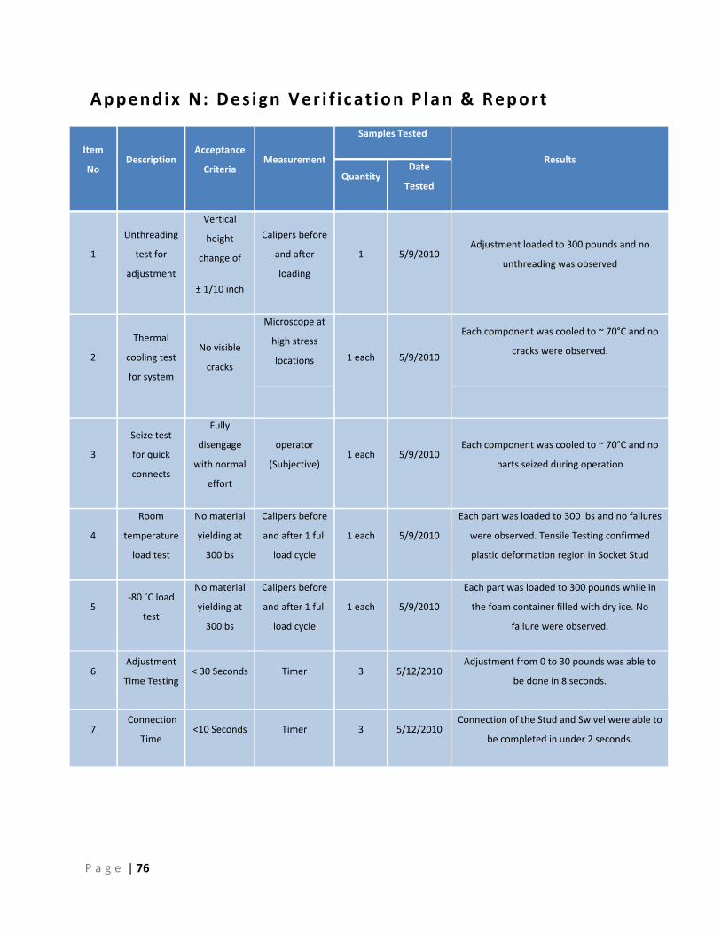
P a g e | 76
Appendix N: Des ign Ver i f i cat ion Plan & Report
Item
No Description
Acceptance
Criteria Measurement
Samples Tested
Results
Quantity Date
Tested
1
Unthreading
test for
adjustment
Vertical
height
change of
± 1/10 inch
Calipers before
and after
loading
1 5/9/2010 Adjustment loaded to 300 pounds and no
unthreading was observed
2
Thermal
cooling test
for system
No visible
cracks
Microscope at
high stress
locations 1 each 5/9/2010
Each component was cooled to ~ 70°C and no
cracks were observed.
3
Seize test
for quick
connects
Fully
disengage
with normal
effort
operator
(Subjective) 1 each 5/9/2010
Each component was cooled to ~ 70°C and no
parts seized during operation
4
Room
temperature
load test
No material
yielding at
300lbs
Calipers before
and after 1 full
load cycle
1 each 5/9/2010
Each part was loaded to 300 lbs and no failures
were observed. Tensile Testing confirmed
plastic deformation region in Socket Stud
5 ‐80 ˚C load
test
No material
yielding at
300lbs
Calipers before
and after 1 full
load cycle
1 each 5/9/2010
Each part was loaded to 300 pounds while in
the foam container filled with dry ice. No
failure were observed.
6 Adjustment
Time Testing < 30 Seconds Timer 3 5/12/2010
Adjustment from 0 to 30 pounds was able to
be done in 8 seconds.
7 Connection
Time <10 Seconds Timer 3 5/12/2010
Connection of the Stud and Swivel were able to
be completed in under 2 seconds.

P a g e | 77
Appendix O: Expendi ture Report
Sub‐Assembly Component / Material Part Number Qty. Actual Cost
Adjustm
ent M
echanism
Compressed Spring
Adjustment
Ø1" ID Aluminum 6061 Tube (MC) 9056K273 3 ft $35.80
Ø1" OD x 5" Chrome‐Silicon Steel Spring (MC) 9573K58 3 $23.49
1‐1/16" Internal Retaining Ring (MC) 91580A216 8 $18.80
Ø1" Aluminum 2024 Bar (MC) 8974K133 3 ft $16.33
8‐32 X5/16 Socket Cap Screw (HD) 3 $1.00
1/4‐20 Threaded Rod (MC) 94400A510 3 ft $9.43
Ø1/4"‐20 Wing Nut Stainless Steel (HD) 5 $6.76
E‐Ring Style Retaining ring (MC) 98408A124 25 $5.22
Ø1/4"‐20 Zinc Plated Steel Eye Bolt (MC) 3014T103 1 $16.22
Quick Con
nect
Swivel Nub
Ø 1 ‐ 1/8" Aluminum 2024 Alloy (AS) 03‐42250‐1 2 ft $22.42
1/2" 303 Steel Rod (MC) 88915K221 1 ft $15.07
Ø1/4"‐20 Zinc Plated Steel Eye Bolt (MC) 3014T103 1 $16.22
Ø1/8" Stainless Steel Dowell Pin (MC) 90145A469 1 $14.97
Ø5/16" OD Compression Spring (MC) 1986K4 1 $11.60
Socket Stud
Ø1" Aluminum 2024 Rod (AS) 03‐42200‐2 3 ft $24.63
Ø3/8" OD Compression Spring (MC) 9657K155 12 $6.58
1/4‐20 X2.5 Socket Cap Screw (MC) 92196A332 10 $4.89
1/4‐20 Hex Nut (HD) 3 $1.00
5/16 Shoulder Screw (MC) 91829A304 3 $11.01
Ø1/4 ‐ 28 SHCS (MC) 92196A332 1 $7.68
Miscellane
ous
Swivels and Connectors
1‐7/8 Bearing Swivel Eye Clevis (MC) 8928T13 3 $202.95
High Strength D Shackel (MC) 3824T33 5 $52.79
Tooling
Ø3/16" X 5" Extended‐reach Drill Bit (MC) 28965A735 1 $9.12
Ø19/64" X 12" Extended‐reach Drill Bit (MC) 2854A35 1 $20.90
Grooving Tool for Retaining Ring (MC) 32335A31 1 $31.66
Testing and Display Fixtures
Lumber (HD) ‐ $25.00
Hardware (HD) ‐ $70.00
Shipping McMaster‐Carr & Aircraft Spruce ‐ ‐ $70.00
Total $751.54


![[Array, Array, Array, Array, Array, Array, Array, Array, Array, Array, Array, Array]](https://static.fdocuments.us/doc/165x107/56816460550346895dd63b8b/array-array-array-array-array-array-array-array-array-array-array.jpg)