1498398162528999000-05211420 · United States Patent (19) Iwashita 54 ADJUSTABLE HEIGHT SUSPENSION...
29
United States Patent (19) Iwashita 54 ADJUSTABLE HEIGHT SUSPENSION MECHANISM FOR TWO-WHEELED MOTOR VEHICLES 75) Inventor: Kanau Iwashita, Saitama, Japan 73) Assignee: Honda Giken Kogyo Kabushiki Kaisha, Tokyo, Japan (21) Appl. No.: 782,904 22 Filed: Oct. 24, 1991 Related U.S. Application Data 63 Continuation of Ser. No. 408,044, Sep. 15, 1989, aban doned. 30 Foreign Application Priority Data Sep. 16, 1988 JP Japan ................................ 63.23.1655 51) Int. Cl. ..................... B60G 17/01; B60G 17/015 52) U.S.C. .................................... 280/703; 280/707; 180/219 58) Field of Search ............... 280/707, 703, 840, 612, 280/702; 364/424.05 56) References Cited U.S. PATENT DOCUMENTS 4,212,484 7/1980 Fujii.................................... 280/707 4,568,101 2/1986 Bleustein ............................. 280/707 4,586,728 5/1986 Tokunaga et al. ... ... 280/703 4,687,223 8/1987 Miyoshi................. ... 280/707 4,691,284 9/1987 Izumi et al........ ... 280/703 4,714,271 12/1987 Buma et al. ......................... 280/707 4,715,616 12/1987 Asami et al. ........................ 280/707 4,741,554 5/1988 Okamoto ............................. 280/703 Ham-m-n RSPRING BOTTOMG SENSOR ||||||IHIIIHHHIII US005211420A 11) Patent Number: 45 Date of Patent: 5,211,420 May 18, 1993 Primary Examiner-Karin L. Tyson Attorney, Agent, or Firm-Lyon & Lyon (57) ABSTRACT A suspension system for two-wheeled vehicles capable of adjusting effective height of the vehicle and the spring rate of the suspension. Damping adjustment mechanisms are also employed. In the front suspension of a two-wheeled vehicle, a left-right suspension mecha nism is employed with one component of the suspension having a variable seat driven by hydraulic pressure. The other component includes two springs in series with a seat therebetween. A hydraulic cylinder may be actu ated to effectively reduce or eliminate the operation of one of the springs to change the spring rate of the sys tem by moving and retaining the seat toward one of the springs. Actuator motors control damping resistance through adjustable damping orifices defined by needle valves and associated seats. A unitary damping and suspension spring mechanism associated with the rear suspension provides a hydraulic cylinder in association with a seat for the suspension spring to vary the height of the vehicle. The cylinder is associated with the damping mechanism concentrically mounted inwardly of the suspension spring and a rubber suspension spring. The adjustable spring seat is positioned about the damp ing mechanism and mounted thereto through the adjust ment mechanism. A further movable seat may be used to control the spring constant of the coil spring and rubber spring suspension mechanism. 11 Claims, 18 Drawing Sheets sa ri-MEDIUM CUTCHSWITCHSENSOR So HARD GEARSHIFT SENSOR Oh-Sisction 2O2 CH O35 C All g MS sysseyir e SSN 103-15snie
Transcript of 1498398162528999000-05211420 · United States Patent (19) Iwashita 54 ADJUSTABLE HEIGHT SUSPENSION...

United States Patent (19) Iwashita
54 ADJUSTABLE HEIGHT SUSPENSION MECHANISM FOR TWO-WHEELED MOTOR VEHICLES
75) Inventor: Kanau Iwashita, Saitama, Japan 73) Assignee: Honda Giken Kogyo Kabushiki
Kaisha, Tokyo, Japan (21) Appl. No.: 782,904 22 Filed: Oct. 24, 1991
Related U.S. Application Data 63 Continuation of Ser. No. 408,044, Sep. 15, 1989, aban
doned.
30 Foreign Application Priority Data Sep. 16, 1988 JP Japan ................................ 63.23.1655
51) Int. Cl. ..................... B60G 17/01; B60G 17/015 52) U.S.C. .................................... 280/703; 280/707;
180/219 58) Field of Search ............... 280/707, 703, 840, 612,
280/702; 364/424.05 56) References Cited
U.S. PATENT DOCUMENTS
4,212,484 7/1980 Fujii.................................... 280/707 4,568,101 2/1986 Bleustein ............................. 280/707 4,586,728 5/1986 Tokunaga et al. ... ... 280/703 4,687,223 8/1987 Miyoshi................. ... 280/707 4,691,284 9/1987 Izumi et al........ ... 280/703 4,714,271 12/1987 Buma et al. ......................... 280/707 4,715,616 12/1987 Asami et al. ........................ 280/707 4,741,554 5/1988 Okamoto ............................. 280/703
Ham-m-n
RSPRING BOTTOMG SENSOR
||||||IHIIIHHHIII US005211420A
11) Patent Number: 45 Date of Patent:
5,211,420 May 18, 1993
Primary Examiner-Karin L. Tyson Attorney, Agent, or Firm-Lyon & Lyon (57) ABSTRACT A suspension system for two-wheeled vehicles capable of adjusting effective height of the vehicle and the spring rate of the suspension. Damping adjustment mechanisms are also employed. In the front suspension of a two-wheeled vehicle, a left-right suspension mecha nism is employed with one component of the suspension having a variable seat driven by hydraulic pressure. The other component includes two springs in series with a seat therebetween. A hydraulic cylinder may be actu ated to effectively reduce or eliminate the operation of one of the springs to change the spring rate of the sys tem by moving and retaining the seat toward one of the springs. Actuator motors control damping resistance through adjustable damping orifices defined by needle valves and associated seats. A unitary damping and suspension spring mechanism associated with the rear suspension provides a hydraulic cylinder in association with a seat for the suspension spring to vary the height of the vehicle. The cylinder is associated with the damping mechanism concentrically mounted inwardly of the suspension spring and a rubber suspension spring. The adjustable spring seat is positioned about the damp ing mechanism and mounted thereto through the adjust ment mechanism. A further movable seat may be used to control the spring constant of the coil spring and rubber spring suspension mechanism.
11 Claims, 18 Drawing Sheets
sa ri-MEDIUM CUTCHSWITCHSENSOR So HARD GEARSHIFT SENSOR Oh-Sisction 2O2 CH
O35 C All g
MS sysseyir e SSN 103-15snie

U.S. Patent May 18, 1993 Sheet 1 of 18 5,211,420

Sheet 2 of 18 5,211,420 May 18, 1993 U.S. Patent
|----- ZZL ZZ @


5,211,420
& & & &~ $ $ $ *: ? & &$ $ $ È $ $
S KNOEN NOEN NON ANNONONOSONANTNO
U.S. Patent

Sheet 5 of 18 5,211,420 May 18, 1993 U.S. Patent
till--ZwyZº zzzzzzzzzzzzzzzzzz

Sheet 6 of 18 5,211,420 May 18, 1993 U.S. Patent
?N Ø
777 W 2. N
8 A3

Sheet 7 of 18 5,211,420 May 18, 1993 U.S. Patent
-- ----?===========•====** **
6.Li
K Sl
29

U.S. Patent May 18, 1993 Sheet 9 of 18 5,211,420
OBJECT OF OPERATING CONTROL CONTROL. ACTION CONDITIONS sensor RONG SENSATION
IMPROVEMENT OF LEGPOSITIO AT VERY LOW OPERATING SPEED
MANNING VEHICLE HEGHT RESPONSE TO INCREASED LOAD
SOFT MEDIUM HARD 3 MODE SELECTION
Ellisi FORCE CONSTAN
soft s s MEDIUM H s
MAINTAINING OW VEHICLE Position AT STOP AND AT VERY LOW SPEED
RESPONSE DEcson RESPONSE
ORONARY TIME TO MANTAN STANDARD VEHICLE HEIGHT
HEIGHT OF LOWERED WEHICLE
RESPONSE
FG 1 7
MANUAL SELECTION
VEHICLE LOWERING AT 0 km/h
VEHICLE SPEED SENSOR
START OF REGULATION A 15 km/h. FOR STANDARD VEHICLE HEIGHT
Fr. SUSP. POSITION CHANGE SENSOR
R. SUSP. POSITION CHANGE SENSOR
BRAKE SENSOR
VEHICLE SPEED SENSOR
VEHICLE RAISING CONTROL AT O - 15 km/h
Fr. SUSP. POSITION SENSOR
START OF REGULATION A 15 km/h FOR STANDARD VEHICLE HEIGHT
R. SUSP. POSITON SENSOR

U.S. Patent
OBJECT OF OPERATING CONTROL CONTROL ACTION CONDITIONS
2 O O Z O u) O C
PREVENTING LOWERING OF VEHICLE REAR WHEN ASCENDING AN UP GRADE
PREVENTING LOWERING OF VEHICLE FRONT WHEN DESCENDING A DOWN GRADE
MA HEIGHT AT HORIZONTAL POSITION
May 18, 1993
NTINING STANDARD VEHICLE
(REAR UP, FRONT DOWN)
DECSON
MANTAINING SANDARD VEHICLE HEIGHT AT HORIZONTAL POSTION
(FRONT UP, REAR DOWN) STANDARD VEHICE
HEIGHT
RSPONSE
FG 18
Sheet 10 of 18
START OF REGULATION AT SPEED 15km/h WHEN FRONT OF VEHICLE IS LOWERED PAST FIXED TIME
START OF REGULATION AT SPEEDS 15 km/h WHEN FRONT OF VEHICLE S LOWERED PAST A FIXED TIME
5,211,420
SENSOR
VEHICLE SPEED SENSOR
Fr. SUSP. POSITION SENSOR
R. SUSP. POSITION SENSOR
VEHICLE SPEED SENSOR
Fr. SUSP. POSITION SENSOR
R. SUSP. POSITION SENSOR

U.S. Patent May 18, 1993 Sheet 11 of 18 5,211,420
OBJECT OF CONTROL CONTROL. ACON DAMPING| PRE
FORCE LOAD
al
OL. A
RUNNING SOFT/MEDIUM/HARD MODE
OPERATING
SENSATION RUNNING MANUA MODE
SWITCH SELECTION
Vehicle speed S6 FRMRR Cush. Disp. Brake S2, S3, S9
Vehicle speed S6 FRRR Cush. Disp. Steering angle S2, S3
Vehicle speed
VEHICLE HEIGHT EWOKMMHR: SART OF HEIGHT ADJUSTMENT Height adjustment is restrained when steering angle switch is on
MAINTAINING IF CAR HEIGHT IS VEHICLE PERMANENTLY MANTANED yer. S6 HGHN ATA SANDARD HEIGHT FRIRR Cush. HEGH RESPONSE TO Disp. ADJUSTMENT NCREASED Hei Steering eight LOAD ad angle justment
is restrained S2S3, S5 When Steering angle Switch is On
Vehicle speed PREVE TING WITH RESPECT TO GROUND YKMHR s ce spee LOWERING AGAINST LOWERING OF OF VEHICLE : AR) rear height is FRRR cush. Disp.
Steering angle
lower than a preset value
REAR WHEN ASCENDING ANUP-GRADE longer than a S2, S3, S5
O BSOS preset r po time interval 5 ac hill climb O MAINTAIN PRESET HEIGHT V10 KM/HR Vehicle speed 3 PREVENTING WITH RESPECT TO GROUND and S6 E LOWERING (AGAINST LOWERING OF front height is FR/RR Cush. goF VEHICLE FRONT) OWer Disp.
FRON, WHEN than a preset Steering DESCENDING Value angle A longer than a S2, S3, S5 DOWN-GRADE preset
time interval
F.G. 19

U.S. Patent May 18, 1993 Sheet 12 of 18 5,211,420
CONTROL ELEMENT
OBJECT OF CONTROL ACTION EN SENSOR dampnel at SRING CON. LOAD STANT
Farr Farr Far Throttle aperture and
ANTI-SOUAT engine speed increase, are both higher than preset values
0.1 - > TIME
SEC RESPONSE
DAMPING FORCE DAMPING FORCE released Throttle Throttle ANT- COMPRESSION 1 Sec aperture and aperture OVE RR EXTENSION later engine speed S4 (ACCUTE decrease, are ACCEL- both greater Engine OFF) OF than presel speed
values S7
(ACCUTE 01 SEC - TIME BRAKING)
SEC RESPONSE
CONTROL CONOTIONS
DAMPING FORCE
FR COMPRESSION increasing BRAKE S9
RR EXTENSION braking force O FR: React directly to braking force RR: Cancel after 1 Sec and return to original position
SHIFT AMPING FORCE Ciutch Switch Clutch Sw, CHANGE O gear position Gear position (RESTRAINT COMPRESSION Switch and Naul OF RR EXTENSON throttle PITCHING) aperture are all pries:
positive S10, S11, S4
FG.2O (CONTINUED)

U.S. Patent May 18, 1993 Sheet 13 of 18 5,211,420
OPERATION SOFT
RR MEDUM Vehicle speed Yl
MODE CHANGE SS ul
RESTRANT Werica OFREAR DAMPING FORCE acceleration of Sensor is JUMPNG RR COMPRESSION front wheel is OFF AT higher than a s F. ROUGH preset value p ROADS
(CONTINUED) FIG.2O
- O C H 2 O s 2. O f O O.

U.S. Patent May 18, 1993 Sheet 14 of 18 5,211,420
N Ge N
77d E6 NYKYN
Gele SSS)
22
NSN
NNY

U.S. Patent May 18, 1993
------Input Signal ----
Sl-NFR G Sensors beneath spring
S2-N FR Suspension Stroke Sensor
S3-N RR Suspension Stroke Sensor
S4 Throttle Sensor
Sen SOr
S61N. Speed Sensor
S7. Ne Pulser
S8-N Running Mode Switch
S5-steering Angle
S9 Brake Switch
SON Clutch Switch
SI - Shift, Position WC
S2-N FR Df Motor Encoder
SI3- RR Df Motor Encoder
S t h
FG, 24.
Sheet 15 of 18
r--- Supension--- Control Unit
2OO Input Interface Circuit
A/D Converter
2O4.
Output Interface Circuit
CPU
Program Map
Input Interface Circuit
2O3
Electric POWer Source
- Output Signal
FR Pre-load Motor
RR Pre-load not or
FR, RR Spring Rate Motor
FR Of Motor
5,211,420
164
:73 41(59)
: 126

U.S. Patent May 18, 1993 Sheet 16 of 18 5,211,420
S
S2 Reading-in of data: Position of Front and Rear Suspensions, Stands and Speedometer
FIG.2s Calculation of Acceleration AV from prior speed Vn-1 and present speed V
gst YES
S7 S2 Objective Stripke Emission of
a- f (V) Signals for Lowering Height
Fig. 13(b)
S8 S3 Opening Heidht Set 9 Oil Cylinder to Reservoir
too low Comparaison of Present and Objective
Stroke
Epission of Signals for oweringt
Height
Erission of Signals for Increasing Height
S4

U.S. Patent May 18, 1993 Sheet 17 of 18 5,211,420
FG. 26 f(Vn) Predetermined
Stroke for G and one rider
Speed Vn
FG 27 Control ored
% % too high Object+5mm
+5mm Permissible Ared u via a w- a - w is a m + iy as a sma wa - - - - - Object
-5mm W. Object-5mm
% Control Ared

U.S. Patent May 18, 1993 sheet 18 of 18 5,211,420
CONTROL CONTROL ACTION CONDITIONS PREVENTION OF DEPRESSION OF VEHICLE REAR OURING RAPO ACCELERATION
THROTTLE POSITION CANCEL THROTTLE.
DAMPING FORCE AFTER EYE POSITON ANTI-SOUATING TEN.H 5. VALUE SENSOR
N coMPH RETURN VEHCLE SPEED U TO RELATION SENSOR Éy ORIGINAL Vicle
- POSITION PE GEARSHIFT
DECISION RESPONSE REACTION 8 PREVENTON OF DEPRESSION OF VEHICLE SE 3 ERONDURINGRAPPDECELERATION (DUE st E TO RELEASE OF THROTTLE, NOT DUE TO PRESET SE ANT-OWING 3 Eton BRAKING) CANCEL VALUE SENSOR, DUE TO DAMPING FORCE AFTER N VEHICLE SPEED THROTTLE . 1 SEC. AND RELATION SENSOR, RELEASE) FR coMPH RETURNTo TO GEAR SHIFT
RF TEN.H ORIGINAL VEHICLE SENSOR POSITION
PREVENTON OF DEPRESSION OF VEHICLE ANT-DIVING FRONT DURING RAPID DECELERATINDUE TO (RAPID BRAKING CANCE NCREASING BRAKE AFTER BRAKING APPLICATION) DAMPING FORCE 1 SEC. AND FORCE
RETURN TO RR TEN.H ORIGINAL
POSITION
ITCH CONTROL WHEN SHIFTNG UPOR DOWN
IDAMPING FORCE CUTCH PITCH INCREASING. CLUTCH ISENSOR,
DURING SPEED RR COMP.H PATTERN OR GEAR SENSOR, CHANGES POSTION SPEED SENSOR
SWITCH IS RPM SENSOR ON DAMPING FORCE
RR TEN.H
MPROVE STABLITY AT HIGH SPEEDS AUTOMATIC MODE CHANGE
REDUCING
SPEEDS ADJUSTMENT >130 FOR V130 NO CHANGE KM/HR HIGH-SPEED WHEN OPERATION SET HARD MEDIUMD- HARD
REDUCTION OF REAR SUSPENSON DAMPING FRONT WHEE PvENToNoFFORWHENPROJECTIONS INROAD ARE G-SENSOR
NeuroMPACTED INOPERATIVEEE RR COMP DAMPING FORCE ROAD ATSPEEPS position IRREGULARITIES SOFT GREATER A SPEEDS MEOUM ULTRASOFT THAN 130 KM/HR co HARD

5,211,420 1.
ADJUSTABLE HEIGHT SUSPENSION MECHANISM FOR TWO-WHEELED MOTOR
VEHICLES
This application is a continuation of application Ser. No. 07/408,044, filed Sep. 15, 1989 now abandoned.
BACKGROUND OF THE INVENTION 1. Field of the Invention The field of the present invention is adjustable sus
pension systems for two-wheeled motor vehicles. 2. Prior Art In recent years there has been a need for suspension
mechanisms for two-wheeled motor vehicles which are adjustable as to suspension characteristics for accom modating different riding conditions and for height adjustment. In the case of automobiles, suspensions accomplishing the foregoing objectives have been de vised. However, the application of such automobile suspension mechanisms to motorcycles and other two wheeled motor vehicles is not practical. With two wheeled motor vehicles, mounting space for any sus pension system is limited and there is no place for such conventional adjustable suspension mechanisms. Fur ther, the weight of such systems is excessive and, in their current form, would severely imbalance the mo torcycle if they could be used at all.
SUMMARY OF THE INVENTION
The intent of the present invention is to solve the aforementioned problems by providing control over the extension and stiffness of the front and rear suspensions in a manner to suit the needs of the rider and the riding conditions. Such a system is capable of being compact and lightweight with a minimum number of compo nents, substantial reliability and minimum energy con sumption.
In an aspect of the present invention, the operation to vary either or both the spring rate or spring extension may be accomplished through hydraulic cylinders which provide for a release of hydraulic pressure when the vehicle is stopped or operated at a very low speed. This causes the vehicle to be lowered to a mechanical stop not requiring continued hydraulic pressure with associated energy consumption.
Thus, height adjustment and spring rate adjustment may be accomplished for two-wheeled vehicles in a compact manner without unnecessarily duplicating components. Other and further objects and advantages will appear hereinafter. A BRIEF DESCRIPTION OF THE DRAWINGS
FIG. 1 is a total plan view of a two-wheeled motor vehicle.
FIG. 2 is a total side view of a two-wheeled motor vehicle.
FIG. 3 is a schematic organization representation of a first preferred embodiment of the present invention. FIG. 4 is a cross-sectional right side view of a portion
of a front suspension mechanism of a preferred embodi ment of the present invention.
FIG. 5 is a detailed view of the circular section la beled V in FIG. 4.
FIG. 6 is a detailed view of the circular section la beled VI in FIG. 4.
FIG. 7 is a detailed view of the circular section la beled VII in FIG. 4.
5
10
15
20
25
30
35
45
50
55
65
2 FIG. 8 is a cross-sectional left side view of a portion
of a front suspension mechanism of a preferred embodi ment of the present invention. FIG. 9 is a detailed view of the circular section la
beled IX in FIG. 8. FIG. 10 is a detailed view of the circular section
labeled X in FIG. 8. FIG. 11 is a cross-sectional side view of a portion of
a rear suspension mechanism of a preferred embodiment of the present invention.
FIG. 12 is a detailed view of the circular section labeled XII in FIG. 1. FIG. 13 is an organizational representation of a sec
ond preferred embodiment of the present invention. FIGS. 14, 15 and 16 are explanatory figures showing
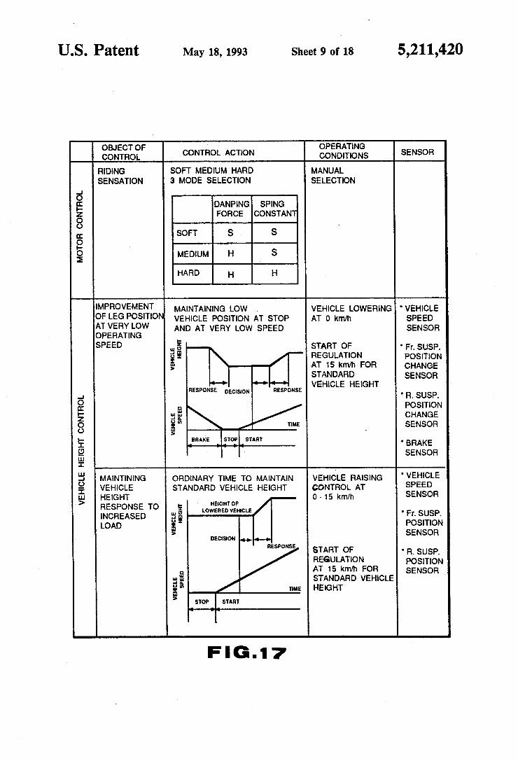
the operation of the height adjustment mechanism of a second preferred embodiment of the present invention. FIGS. 17, 18 and 28 are explanatory figures showing
the overall operation of a suspension mechanism of a first preferred embodiment of the present invention. FIGS. 19 and 20 show the operation of the total sus
pension mechanism of a second preferred embodiment of the present invention. FIGS. 21, 22 and 23 are explanatory figures showing
the operation of the hydraulic components of the ad justable spring constant mechanism of the second pre ferred embodiment of the present invention. FIG. 24 is a flow diagram of the governing apparatus
10 of the second preferred embodiment of the present invention. FIGS. 25, 26 and 27 are flow diagrams for explaining
the reactions and responses of the suspension system of the second preferred embodiment of the present inven tion.
DETAILED DESCRIPTION OF THE PREFERRED EMBODIMENTS OF THE
PRESENT INVENTION
In the following sections, two preferred embodiments of the present invention will be described with refer ence to the drawings. The suspension apparatus of the present preferred
embodiment, as seen in FIGS. 1, 2, and 3 is fundamen tally comprised of paired right and left front suspension units 2, 3 respectively, which support the front axle 1; a unitary rear suspension unit 7 situated between the side frame at the lower portion of seat 4 and rear fork 6, connecting with rear fork 6 via link 6a; and a control unit 8 which supplies hydraulic fluid to the respective hydraulic sections of left and right suspension units 2, 3 and rear suspension unit 7 effecting height control as well damping energy control by means of on electric signals sent to an intermediate control motor. For the above mentioned paired left and right front
suspension units 2, 3, the right unit 2 has both a vehicle height governing and damping force governing func tion while the left suspension unit 3 has a spring con stant adjusting function. The rear suspension unit 7 has vehicle height governing and damping force governing function as well as spring constant adjusting function. The control unit 8 is composed of an oil pressure man aging unit 9 which supplies hydraulic fluid at a fixed pressure to the respective hydraulic cylinders of left and right suspension units 2, 3 and rear suspension unit 7 and which conversely releases the above mentioned applied hydraulic pressure; and a governing apparatus 10 by which means electric signals are sent to the above men tioned oil pressure managing unit 9 in response to the

5,211,420 3
vehicles operating conditions thereby controlling oil pressure managing unit 9 while at the same time, di rectly sending electric signals to control motors pro vided on suspension units 2 and 7. The following is a supplementary explanation for the
layout of suspension accessories and the primary parts of a motorcycle with reference to FIGS. 1 and 2.
G-sensor S is installed at the lower end of left front suspension 3 while stroke sensor S2, which measures the height of the vehicle (or the length of the front suspen sion unit), is attached to the outside of right front sus pension 2. Numbered 16 is the fuel tank which is located over
the vehicle engine. At the front end of the tank is filler tube 162, while CPU 202, which controls the suspen sion, is mounted in a hollow spot at the rear end of the fuel tank 161. Under the rear end of the fuel tank are reserve tank
144b which stores hydraulic fluid and pump 142 with motor 141 which feeds the suspension fluid by pressure.
Control valves coded 148A, 148B, 148C, 150A, 150B, and 150C constituting oil pressure managing unit 9 are placed on base 159 between the reserve tank and the pump. Base 159 is held by a bracket, not indicated in the figures, extending from frame 5.
Stroke sensor S3 for detecting the height of the rear body is attached near pivot P of rear fork 6. The main part of stroke sensor S3 is installed on rear stay 5a of frame 5 by brackets while its moving part is attached to rear folk 6 by a linkage. Accumulator 146, which stores the suspension fluid, is placed in the rear cover behind seat 4. In the following section, the above described components will be described in further detail with reference to FIGS. 4 to 7.
RIGHT FRONT SUSPENSON UNIT
The above mentioned right front suspension unit 2 has a damping force governing function as well as a pre-load application vehicle height adjusting function. (See FIGS. 4, 5, 6, and 7). Fork pipe 12 is installed within bottom case 11 so as
to slide freely within, this bottom case 11 being a cylin drical pipe having a closed bottom end. The bottom case 11 is fixed on the previously mentioned front axle 1 and fork pipe 12 is fixed to the side of the vehicle's frame via top and bottom bridges. Prior to installing fork pipe 12, a coil spring as well as an oil damping apparatus, or the like were inserted inside it as a unit in the form of a cartridge 13.
Coil spring 13 is situated along the central axis of fork pipe 12. Operating together as a unit, fork pipe 12 and coil spring 13 are installed at the outer circumference of load pipe 15. The upper end of load pipe 15 is supported by pre-load adjuster piston 16 via spring seat 17. The lower end of load pipe 15 is supported by cylinder 18, which is inserted within bottom case 11, via a spring seat 18a, Concerning the lower portion of load pipe 15, hy
draulic chamber 20 is formed inside load pipe 15 while other hydraulic chambers 21 and 22, which are sepa rated into upper and lower chambers by piston valve 19 attached to the tip of load pipe 15, are set inside of cylinder 18. As FIG. 5 shows, hydraulic chambers 20 and 21 are
connected to each other by port 23 which is cut into the side wall of load pipe 15. Similarly, hydraulic chambers 20 and 22 are connected to each other by through port 25 in plug 24 which is fixed to the lower tip of load pipe
5
O
15
20
25
30
35
40
45
50
55
60
4. 15. At the upper end of through port 25 is check ball 25a. This ball contacts the upper valve seat and stops the rising flow of oil when in its upper position, and it controls oil flow into through port 25 when in its lower position. Hydraulic chambers 21 and 22 are connected to each other by oil passage 26 in piston valve 19. This oil passage, as indicated in FIG. 5, has two types of channels; one is for upward flow and the other allows downward flow. Some of the type channels are posi tioned one after the other around the periphery of pis ton valve 19. At the upper part of oil passage 26, there is check valve 28 which is closed by a spring while plate valve 29 is set at the lower part. When both check valve 28 and plate valve 29 are closed, oil passage 26 allows upward and downward flow of oil through the oil chan nels.
In this piston valve 19, check valve 28 opens allowing smooth upward oil flow and plate valve 29 controls and creates a certain amount of resistance in the oil flow downward. As shown in FIG. 6, hydraulic chamber 22 at the
lower part of cylinder 18 is, by oil passages 30 and 31, connected with oil chamber 32, which is formed be tween cylinder 18 and bottom case 11.
Oil passage 30 reaches oil chamber 32 through port 35 cut into the side wall of the cylinder and piston valve 34, which is filed on the periphery of the tip of socket bolt 33. The bolt is fixed to the bottom of bottom case 11.
Oil passage 31, also reaches oil chamber 32. This passage goes through port 36, which runs along the axis of socket bolt 33; clearance 1 between valve seat 37 and needle 38; and ports 40 pass through oil lock piece 39.
Piston valve 34 is similar to piston valve 19 in terms of structure. Check valve 34b is at the upper part of oil passage 34a while plate valve 34c is placed at the lower part. Thus smooth upward flow of oil is secured while a certain resistance grows in the channels when oil goes downward,
Clearance 1 between valve seat 37 and needle 38 is variable because needle 38 is moved and controlled by damping force adjustable motor 41. This adjustment is mainly for controlling damping force when right front suspension unit 2 is in its retraction phase. Concerning the upper portion of load pipe 15 and
other components in its vicinity, as FIG. 7 indicates, cap 50 is fixed above load pipe 15 and cylinder 51 is fixed to cap 50 between fork pipe 12 and load pipe 15. The pre-load adjuster piston 16 is in the cylinder. Hydraulic chamber 52, which is formed on the periphery of load pipe 15 positioned in cylinder 51, is connected to con trol unit 8 through oil passage 53. Head 50a of cap 50 functions as a stopper which
determines the position of pre-load adjuster piston 16 to where the piston retracts as oil is released from hydrau lic chamber 52.
Hydraulic chamber 20 of load pipe 15 is connected to cylinder 51 and oil chamber 58, which is formed be tween the periphery of pre-load adjuster piston 16 and fork pipe 12, through clearance 12 located between valve sheet 54 and needle 55, port 56 on the side wall of load pipe 15, and passage 57 through cap 50. Oil flows from hydraulic chamber 20 to oil chamber 58 through clearance 12, port 56, and passage 57. Coil spring 13 is seated in oil chamber 58. This oil chamber is also joined with oil chamber 32 through a port cut in spring seat 18a.

5,211,420 5
Clearance 12 between valve sheet 54 and needle 55 is variable as the needle is moved by damping force ad justable motor 59. This adjustment is mainly for con trolling damping force when the suspension unit is ex tending.
In FIG. 4, rebound stopper 60, rebound spring 61, and rod guide 62 can be seen. As seen in FIG. 1, G sensor S1 is installed on the lower end of right front suspension unit 2 and functions to detect increasing velocity of movement in the axial direction of the lower end of right front suspension unit 2. Stroke sensor S2 serves to detect expansion and contraction of right front suspension unit 2. For stroke sensor S2, the casing is fixed on the bottom bridge, and extending from the casing, a link is attached, the end of which is pivotably mounted on botton case 11.
In the following is a description of the action of right front suspension unit 2. When right front suspension unit 2 is compressed due
to external force, the pressure in hydraulic chamber 22 located below cylinder 18 will increase while that in hydraulic chamber 21 placed above the same cylinder will decrease. Since check valve 28 is opened by a pres sure differential, oil will swiftly flow from hydraulic chamber 22 to hydraulic chamber 21 through oil pas sage 26 of piston valve 19. Moreover, the oil in hydrau lic chamber 22 will never flow to hydraulic chamber 20 in load pipe 15 through port 25 because of check ball 25a which is seated in its upper part. At this time, load pipe 15 will travel down into cylin
der 18. Thus, the total capacity of hydraulic chamber 21 and hydraulic chamber 22 will decrease by an amount equal to this entry of the rod. Surplus oil or an amount of oil equal to this difference should naturally flow elsewhere, that is, as illustrated in FIG. 6, to oil cham ber 32 through oil passage 30 and oil passage 31.
Passage resistance to oil running through oil passage 34a of piston valve 34 is fixed by adjusting plate valve 34c while clearance 11 between valve seat 37 and needle 38 is adjustable because needle 38 is adjusted by damp ing force adjustable motor 41. By setting clearance 11 at a desired value, the damping force of right front suspen sion unit 2 is controlled when the suspension contracts. When right front suspension unit 2 extends, the pressure in hydraulic chamber 21 will increase and that in hy draulic chamber 22 will decrease.
Since check valve 28 is closed by a pressure differen tial, oil swiftly rushes from hydraulic chamber 21 to hydraulic chamber 22 through one of the oil passage 26 connected to plate valve 29. At this time, a certain amount of damping force can be obtained due to the action of plate valve 29.
Moreover, the oil in hydraulic chamber 21 progresses to hydraulic chamber 20 inside load pipe 15 mainly through port 23 in load pipe 15. Thus, the pressure therein increases.
Oil runs from hydraulic chamber 20, as shown in FIG.7, to the outside oil chamber 58 through clearance 12 between valve sheet 54 and needle 55, and port 56 and passage 57. During this operation, clearance 12 can be adjusted by moving needle 55 with damping force adjustable motor 59. By setting clearance 12 at a desired value, the damping force of right front suspension unit 2 is controlled when the suspension unit extends. On the other hand, although the pressure in hydraulic
chamber 22 decreases, check valve 34b of piston valve 34 is immediately opened due to a pressure differential and the oil in oil chamber 32 flows into hydraulic cham
10
15
20
25
30
35
45
50
55
65
6 ber 22 through oil passage 34a. The pressure in the hydraulic chamber never decreases beyond a certain value and therefore vapor never forms within. An additional amount of oil flows into hydraulic
chamber 22 through oil passage 31 which consists of port 40 in oil lock piece 39 and clearance 11 between needle 38 and valve seat 37. When a desired amount of oil is supplied from oil
pressure managing unit 9 to hydraulic chamber 52 at the top of fork pipe 12, pre-load adjuster piston 16 is pressed downward as well as spring seat 17. FIG. 4 shows the state in which pre-load adjuster
piston 16 is pressed downward from when the vehicle is in an elevated position. In this manner, fork pipe 12 is raised by the reaction force of coil spring 13 when a specific load is applied to coil spring 13. The front of the vehicle is thus lifted.
Conversely, pre-load adjuster piston 16 will with draw into cylinder 51 and touch head 50a as a result of pressure reduction of hydraulic chamber 52. Thus, the front of the vehicle will be lowered due to a decrease in reactive force from coil spring 13. The following is a summary of the preceding descrip
tion: 1. It is possible to adjust the damping force of 2 in the
retraction phase by controlling 41. 2. It is possible to adjust the damping force of 2 in the
extension phase by controlling 59. 3. It is possible to adjust the height of the front of the
vehicle by controlling the oil supply to hydraulic cham ber 52 in cylinder 51 with oil pressure managing unit 9.
In the above described and illustrated example, through the action of damping force adjustable motor 41 and damping force adjustable motor 59, needle 38 and needle 55 are caused to move. Although the gaps between the respective needles and valve seats are ad justed, it is also suitable to change the oil flow resistance by adjusting the respective orifices through the action of damping force adjustable motor 41 and damping force adjustable motor 59.
LEFT FRONT SUSPENSION UNIT Left front suspension unit 3 has the capability of
changing the spring constant as a whole. (See FIGS. 8, 9, and 10). Fork pipe 71 is installed within bottom casing 70 so as
to slide freely within, this bottom casing 70 being a cylindrical pipe having a closed bottom end. In fork pipe 71, coil springs 72 and 73, of different lengths are seated in series.
Seat pipe 75 is fixed by socket bolt 74 to bottom cas ing 70. The lower end of the longer coil spring 72 touches the upper end of seat pipe 75. Hydraulic cham ber 76 is between bottom casing 70 and seat pipe 75. Hydraulic chamber 76 is divided into upper hydraulic chamber 79 and lower hydraulic chamber 80 by divider 78 which has free valve 77 at the intermediate step of seat pipe 75. Upper hydraulic chamber 79 is connected with oil
chamber 82 through port 81 in the side wall of seat pipe 75. Lower hydraulic chamber 80 is also joined with oil chamber 82 through oil lock valve 83, oil passage 84a of antilock dive mechanism antilock dive mechanism an tilock dive mechanism 84, and port 85 running through the lower part of seat pipe 75 connected thereto.
Fixed on the upper point of fork pipe 71 is spring constant adjusting cylinder 86 and spring constant ad justing piston 87 is inserted therein. The periphery of

5,211,420 7
spring constant adjusting cylinder 86 is in contact with the upper end of the shorter coil spring 73 through piston stopper bolt 88.
In contact with the lower end of spring constant adjusting piston 87 is spring seat 90 which is also sand wiched between coil spring 72 and coil spring 73. Hy draulic chamber 91 in spring constant adjusting cylinder 86 is connected to oil pressure managing unit 9 through oil passage 92 running around the upper end of spring constant adjusting cylinder 86.
In the following is a description of the action of left front suspension unit 3. When left front suspension unit 3 is compressed due
to external force, the pressure in lower hydraulic cham ber 80 located outside seat pipe 75 will increase and that of upper hydraulic chamber 79 will decrease. Since free valve 77 is opened by a pressure differential, oil in lower hydraulic chamber 80 will flow up to upper hydraulic chamber 79 through divider 78 and prevent the pressure of the same from dropping. At the same time, the total capacity of upper hydrau
lic chamber 79 and lower hydraulic chamber 80 will decrease by an amount equal to the entry of fork pipe 71. Surplus oil or an amount of oil equal to this differ ence will tend to flow into oil chamber 82 through oil lock valve 83 and oil passage 84a of antilock dive mech anism 84.
Braking is applied to the front wheel at this moment. When a prescribed compression force is transferred from the brake system to antilock dive mechanism 84, piston 84b will travel toward valve seat 84d and oppose the excess force of spring 84c. Oil passage 84a will be closed or narrowed and passage resistance will grow larger, resisting the force on fork pipe 71. As a result, it is possible to prevent the front of the vehicle from div ling.
Conversely, when left front suspension unit 3 ex tends, the pressure in upper hydraulic chamber 79 will increase whereas that in lower hydraulic chamber 80 will decrease. The oil in upper hydraulic chamber 79 will flow into oil chamber 82 through port 81 in seat pipe 75. Due to the oil flow as well as the pressure differential, oil lock valve 83 will open. The oil in oil chamber 82 will therefore rush into lower hydraulic chamber 80 through seat pipe 75 on the lower side wall of seat pipe 75 and oil lock valve 83. When oil under the prescribed pressure is transferred
from oil pressure managing unit 9 to hydraulic chamber 91 at the upper part of suspension unit, spring constant adjusting piston 87 will extend and spring seat 90 will be lowered. The load of the shorter coil spring 73 will be reduced while that on the longer coil spring 72 will increase. It is mainly the longer spring which will con tribute to the action of the suspension unit. In fact, it can be said that if the number of coil spring turns is changed, the spring constant of the suspension is subsequently altered as a whole. If the supply of oil to hydraulic chamber 91 is stopped and the pressure in the same is released, spring constant adjusting piston 87 will return to its original position and both coil spring 72 and coil spring 73 will contribute to the action of the suspension unit. The following is a summary of the above description: 1. It is practical to adjust the spring constant of left
front suspension unit 3 by controlling the oil supply to hydraulic chamber 91 of spring constant adjusting cyl inder 86 with oil pressure managing unit 9.
5
10
15
20
25
30
35
45
SO
55
65
8 REAR SUSPENSION UNIT
Rear suspension unit 7 has the functions of adjusting damping force, adjusting the height of the vehicle al lowing preload, and altering its spring constant, As FIG. 11 illustrates, located from the top to the
bottom are spring constant adjusting body 100, adjust ing pipe 102 which is fixed to spring constant adjusting body 100 with stopper nut 101, and main pipe 103 in serted into adjusting pipe 102 so as to slide freely within.
Spring constant adjusting body spring constant ad justing body 100 is fixed to the vehicle body frame while main pipe 103 is, as shown in FIG. 2, connected with link 6a extending from rear fork 6. On the periphery of main pipe 103, coil spring 104 is
installed. The lower end of coil spring 104 is supported by spring seat 105 which is fixed to main pipe 103, and the upper end is firmly held by preload adjuster piston 108 through spring seat 106 and spring seat 107.
Preload adjuster piston preload adjuster piston 108 is set so as to slide freely within preload adjuster cylinder 109 which is fixed on the periphery of adjusting pipe 102. Preload adjuster cylinder 109 is connected to oil pressure managing unit 9 through the prescribed oil passage 111. Bottom 109a of preload adjuster cylinder 109 will
function as a stopper determining the travel limit of preload adjuster piston 108 when oil in hydraulic cham ber 110 is released and the piston returns. At the upper part of spring constant adjusting body
100, a hollow rod 112 is fixed along the axis thereof. Inside main pipe 103, hydraulic chamber 113 is formed with its lower end divided by free piston 114 and its upper end by rod guide casing 115. This hydraulic chamber 113 is divided into upper chamber 117 and lower chamber 118 by piston valve 116 which is fixed to the end of hollow rod 112. Piston valve 116 has external port external port 119 and internal port 120 on its exter nal and internal sides respectively.
Since external port 119 has plate valve 121 on its upper end, it allows oil flow from lower chamber 118 to upper chamber 117 applying a prescribed amount of resistance to the flow and thereby stops oil from flow ing in the opposite direction.
Conversely, internal port 120 allows oil flow from the upper chamber to the lower one with plate valve 121a placed at this lower part applying a prescribed resis tance. Lateral port 122 is formed in the side wall of hollow rod 112 facing upper chamber 117. This lateral port 122 reaches a clearance formed between hollow rod port 112a and the periphery of needle 123 which penetrates hollow rod port 112a. Through this particu lar clearance, upper chamber 117 is connected to lower chamber 118. Valve seat 124 is positioned at the lower end of nee
dle 123. Needle 123 is moved along the axis of spring constant adjusting body 100 by damping force adjusting motor 125 which is installed on the outside of the same cylinder body. An inert gas, for example, nitrogen, is charged in lower chamber 126 of free piston 114. When rear suspension unit 7 contracts and extends, hollow rod 112 enters and withdraws from upper chamber 117 and lower chamber 118. lower chamber 126 absorbs the change in the total capacity of the two chambers arising from the reciprocating action of the suspension by means of movement of free piston 114. On the periphery of hollow rod 112, as well as inside
adjusting pipe 102, rubber spring 130 is installed. In

5,211,420 stead of rubber, other materials may be used for this spring, for example, a coil spring. The lower end of rubber spring 130 is in contact with
end plate 131 supported by the upper tip of main pipe 103 while its upper end touches the lower surface of 5 spring constant adjusting piston 132. Spring constant adjusting piston 132 is inserted so as to slide freely within spring constant adjusting body 100. Hydraulic chamber 135 is formed between spring constant adjust ing piston 132 and piston base 134 of which the upper tip is held by lock nut 133. Hydraulic chamber 135 is connected with oil pressure managing unit 9 by oil passage 136. As shown in FIG. 2, stroke sensor S3 is equipped
between the body frame and rear fork 6 to detect the amount of the rear suspension unit's contraction and extension.
In the following section, the action of rear suspension unit 7 will be described. When rear suspension unit 7 is compressed due to
external force, the pressure in lower chamber 118 will increase and that in upper chamber 117 will decrease. Since plate valve 121 opens in response to a pressure differential, oil in lower chamber 118 will flow to upper chamber 117 mainly through external port 119 of piston valve 116 with a prescribed passage resistance. At the same time, hollow rod 112 enters upper chamber 117 and lower chamber 118 and surplus oil will be absorbed by free piston 114 as it travels downward. Even so, damping force will be obtained as oil goes through clearance 13 formed between needle 123 and valve seat 124. When rear suspension unit 7 extends, on the other hand, the pressure in upper chamber 117 increases and that in lower chamber 118 decreases.
Since plate valve 121 is closed, oil in upper chamber 117 cannot flow through external port 119. Thus, oil will flow to lower chamber 118 through internal port 120, lateral port 122 of hollow rod 112, and a clearance formed at the periphery of the needle. Passage resis tance in internal port 120 is fixed while that in the nee dle periphery will be freely adjusted by the movement of 123 which is controlled by damping force adjusting motor 125 in clearance 13 between valve seat 124 and needle 123. The damping force of rear suspension unit 7 during the extension phase can therefore be specified at any desired rate. When oil under a prescribed pressure is transferred
from oil pressure managing unit 9 to hydraulic chamber 110 in preload adjuster cylinder 109, lower chamber 118 will be forced downward and, at the same time, spring seat 106 and spring seat 107 will travel downward as well and a prescribed load will be applied to coil spring 104. The reactive force of coil spring 104 will then push preload adjuster cylinder 109 and spring constant ad justing body 100, thus, the rear of the vehicle will be raised.
If the pressure in hydraulic chamber 110 is released in the above described state, preload adjuster piston 108 will retract into preload adjuster cylinder 109 and contact bottom 109a, as shown in FIG. 11. Also, the reactive force of coil spring 104 will decrease and the rear of the vehicle will consequently be lowered. When oil under a prescribed pressure is supplied from
oil pressure managing unit 9 to hydraulic chamber 135 in spring constant adjusting body 100, hydraulic cham ber 135 will travel downward pushing rubber spring 130.
O
15
O As described above, rubber spring 130 is given an
initial load. The spring will then be under load so as to obtain a large elastic coefficient. As a result, the overall spring constant of the rear suspension, which is derived from rubber spring 130 and coil spring 104 will be in creased.
If the supply of oil to hydraulic chamber 135is cut off and the pressure therein is released, spring constant adjusting piston 132 will return to its original position and the prescribed load on rubber spring 130 will be canceled. In other words, the overall spring constant of the rear suspension will be reduced. The following is a summary of the previous descrip
tion of the action of rear suspension unit 7: 1. It is possible to adjust the damping force of rear
suspension unit 7 during its contraction and extension
20
25
30
35
45
SO
55
65
phases by controlling damping force adjusting motor 125.
2. It is possible to adjust the height of the rear of the vehicle by controlling the supply of oil to hydraulic chamber 110 in preload adjuster cylinder 109 with oil pressure managing unit 9.
3. It is practical to adjust the spring constant of rear suspension unit 7 by controlling the oil supply to hy draulic chamber 135 in spring constant adjusting body 100 with oil pressure managing unit 9.
OIL PRESSURE MANAGING UNIT
First Preferred Embodiment
A first preferred embodiment of oil pressure manag ing unit 9, as shown in FIG. 3, will be described in the following.
Oil pressure managing unit 9 is a device which in cludes a control motor and hydraulic control valves which are controlled according to electrical signals from governing apparatus 10, and supplies and releases hydraulic fluid under a prescribed pressure to and from right front suspension unit 2, left front suspension unit 3, and rear suspension unit 7. As shown in FIG. 2, when . mounted on the vehicle frame, oil pressure managing unit 9 is positioned under or to the rear of fuel tank 161 so as to avoid the adverse effect of mud, water, and the like. The area generally indicated in FIG. 3 by 140 is a
system to deliver a fixed amount of oil at a fixed pres sure. Its components include gear pump 142 which is connected with motor 141; a relief valve 144a provided on the outputside of gear pump 142; a reserve tank 144b connected with the input side of gear pump 142. With such a system, even when the speed of motor 141 changes, the oil pressure on the gear pump 142 side of relief valve 144a remains constant and surplus oil is caused to return to gear pump 142 via return circuit 144. This oil will be introduced to oil passage 143 by gear
pump 142. Return circuit 144, with which relief valve 144A is equipped, is connected to the base of oil passage 143. Surplus oil will be returned to reserve tank 144b through the return circuit 144 when the pressure of oil passage 143 exceeds a certain value. Thus, the pressure in oil passage 143 is kept within a certain range. One-way valve 145 is installed in oil passage 143 as
well as is accumulator 146 positioned distal to one-way valve 145. The end of oil passage 143, which is closer to the accumulator, is divided into three branches 147A, 147B, and 147C. Each of the branches is equipped with electric valves 148A, 148B, and 148C, the outputs of

5,211,420 11
which are connected to hydraulic chambers 52,91, 110, and 135. An outward oil passage 147A extends from electric
valve 148A. This oil passage forks into two passages, 147Aa and 147Ab and these two passages are connected to hydraulic chamber 52 and hydraulic chamber 135, respectively.
Return oil passages 149A; 149B, and 149C return oil from outward oil passages 147A, 147B, and 147C after passing through the respective hydraulic chambers and these return oil passages are equipped with electric valves 150A, 150B, and 150C, respectively. These oil passages are joined together and connected into one oil passage, oil passage 151. Oil passage 151 is connected with reserve tank 144b. On outward oil passages 147A, 147B, and 147C, one-way valves G1, G2, and G3 are installed. As FIGS. 1 and 2 show, electric valves 148A, 148B,
148C, 150A, 150B, and 150C are all fixed on base 159. Also, one-way valves G1, G2, and G3 are integrated in base 159.
Second Preferred Embodiment
A second preferred embodiment of oil pressure man aging unit 9, as shown in FIG. 13, will be described in the following.
Oil pressure managing unit 9 is a device which in cludes a control motor and hydraulic control valves which are controlled according to electrical signals from governing apparatus 10, and supplies and releases hydraulic fluid under a prescribed pressure to and from right front suspension unit 2, left front suspension unit 3, and rear suspension unit 7. As shown in FIG. 2, when mounted on the vehicle frame, oil pressure managing unit 9 is positioned under or to the rear of fuel tank 161 so as to avoid the adverse effect of mud, water, and the like. The area generally indicated in FIG. 3 by 140 is a
system to deliver a fixed amount of oil at a fixed pres sure. Its components include gear pump 142 which is connected with motor 141; a relief valve 144a provided on the outputside of gear pump 142; a reserve tank 144b connected with the input side of gear pump 142. With such a system, even when the speed of motor 141 changes, the oil pressure on the gear pump 142 side of relief valve 144a remains constant and surplus oil is caused to return to gear pump 142 via return circuit 144. This oil will be introduced to oil passage 143 by gear
pump 142. Return circuit 144, with which relief valve 144A is equipped, is connected to the base of oil passage 143. Surplus oil will be returned to reserve tank 144b through the return circuit 144 when the pressure of oil passage 143 exceeds a certain value. Thus, the pressure in oil passage 143 is kept within a certain range. The output of gear pump 144a is divided into three
branches which communicate with the hydraulic cham bers 52, 91, 110, and 135 via oil conduits 150, 151, and 152, thereby supplying oil at a fixed pressure.
Oil conduit 150 communicates with an intercon nected pair of preload valves 153 and 154 which then in turn connect via their terminal ends with preload servo valve 155. Preload valves 153 and 154 are constructed identically and contain spools 156 and 157 which are urged by spring 158 in the direction indicated as X in FIG. 13. An end of each spool 156 and 157 protrudes outside their respective preload valves, and by means of these respective protruding portions 156a and 157a which make contact with the undulating surface of
O
15
20
25
30
35
40
45
SO
55
65
12 cylindrical cam 159, each spool 156 and 157 is caused to operate back and forth in the directions indicated as X and Y in FIG. 13, Cylindrical cam 159 is caused to rotate by preload control motors 160.
Port 153a of preload valve 153 connects with the above mentioned oil conduit 150. By means of a second port 153b, the oil conduit continues to connect with port 154a on neighboring preload valve 154. Similarly, port 153c continues the oil conduit which then connects with port 155a on servo valve 155. Furthermore, addi tional ports 153d and 153e continue the oil conduit thereby connecting with reserve tank 144b. Port 154b of the opposite preload control valve 154 continues the oil conduit thereby connecting with port 155b of servo valve 155. Additional ports 155c and 155d continue the oil conduit thereby connecting with reserve tank 144b. Port 155c of servo valve 155 continues as oil conduit 161 and connects with hydraulic chamber 52 of right front suspension unit 2. Additional port 155d continues the oil conduit connecting with reserve tank 144b. Check valve 162 and flow control valve 163 are pro vided in series on the above mentioned oil conduit 161.
Similarly, oil conduit 161, identical to the above, by means of preload valve control motor 164, spools of paired preload valves 166 and 167 are caused to operate in a reciprocating manner by the action of the undulat ing surface of cylindrical cam 165.
Port 168a of servo valve 168 continues as oil conduit 169 thereby connecting with hydraulic chamber 110 of rear suspension unit 7. Check valve 170 and flow con trol valve 171 are provided in series on the above men tioned oil conduit 169. In the following, the operation of valves 166, 167, 168 which are substantially identical will be described.
Similar to the above, spring constant control valves 175 and 176 connected with an end of oil conduit 152 are operated by the reciprocal action of the cylindrical cam 174 on spring constant control motor 173, and on the opposite end of oil conduit 152, spring constant control valve 177 is provided. Port 177a of servo valve 177 continues as oil conduit 178 to connect with hy draulic chamber 91 of left front suspension unit 3. Simi larly, port 177b of servo valve 177 continues as oil con duit 179 to connect with hydraulic chamber 135 of rear suspension unit 7.
In the following, the function of oil pressure manag ing unit 9 will be described. The height controlling function of right front suspen
sion unit 2 as well as rear suspension unit 7 is carried out through the action of control motors 160 and 164 based on changes in the vehicle velocity, the rotation of con trol motors 160 and 164 being mediated and transmitted by cylindrical cams 159 and 165 as described above. This action is described in the Tables and 2 below.
TABLE 1.
- Preload Control - Front Cam Cann
Valve 154 Position Wave 153 Position
Start Engine Off Trough Off Trough Speed Off Trough On Crest S10 km/h Standard On Crest On Crest Height Speed Off Trough Off Trough 20 km/h

5,211,420 13
TABLE 2 Preload Control - Front
Cam Cam Valve 66 Position Valve 167 Position
Start Engine Off Trough Off Trough Speed Off Trough On Crest S 10 km/h Standard On Crest On Crest Height Speed Off Trough Off Trough 20 km/h
First explaining the hydraulic operation and the like of right front suspension unit 2, when the vehicle first starts and is at a velocity of 0 km/h, the point at which the cam 159 surface meets the spools of control valves 153 and 154 is at a trough for both, thus both are in the off condition. As shown in FIG. 14, by virtue of the grooves on
spool 156 of valve 153, ports 153a and 153b are in com munication, and ports 153c and 153e are in communica tion. Similarly, ports 154b and 154d on valve 154 are in communication. Accordingly, oil introduced at a fixed pressure from oil conduit 150 runs through port 153a, port 153b, and through port 154a where it stops. While port 155a of servo valve 155 communicates with ports 153c and 153e of valve 153, similarly, port 155b of servo valve 155 communicates with ports 154b and 154d of valve 154 through all of which hydraulic pressure is applied. Accordingly, the hydraulic chamber 155e at the bottom part of servo valve 155 is caused to open even though hydraulic pressure is not applied through the respective ports. Because a fixed pressure is applied to port 155c due to the effect of coil spring 13 on right front suspension unit 2, piston 155f within servo valve 155 is caused to depress, whereby finally ports 155a and 155c communicate. By this effect, the oil of hydraulic chamber 52 of right front suspension unit 2 passes through oil conduit 161, ports 155c and 155a of servo valve 155, ports 153c and 153e of control valve 153, finally returning to reserve tank 144b. For this reason, the front of the vehicle is depressed without applying a fixed load. The related hydraulic operation of rear suspension
unit 7 is the same as the above, by which means the vehicle rear can be lowered. Thus the vehicle as a whole may be lowered and the driver may easily mount the vehicle. When the vehicle speed increased above 10 km/h,
control motor 160 rotates, control valve 153 is in the ON condition, control valve 154 is in the OFF condi tion. As shown in FIG. 15, ports 153a, 153b, and 153c of valve 153 communicate as do ports 154b and 154d of valve 154. Accordingly, hydraulic pressure is not ap plied to hydraulic chamber 155e of servo valve 155 and piston 155f remains depressed. Therefore, oil is intro duced at a fixed pressure to port 155a by oil conduit 150 through ports 153a and 153c of valve 153. This oil passes from port 155c through oil conduit 151 whereby it is sent to hydraulic chamber 52 of right front suspen sion unit 2, whereby accompanying the movement of its piston, a fixed load is applied to coil spring 13, and by means of its opposing force, the front end of the vehicle is caused to raise. The related hydraulic operation of rear suspension
unit 7 is the same as the above, by which means the vehicle rear can be raised. Thus the vehicle as a whole may be easily raised.
5
10
15
20
25
30
35
45
50
55
65
14 After completion of the above described operation,
control motor 160 is rotating, and control valves 153 and 154 are both in the ON condition. As shown in FIG. 16, ports 153a and 153c of valve 153 communicate as do ports 154a and 154b of valve 154. Accordingly, hydrau lic pressure is applied to hydraulic chamber 155e of servo valve 155 and the difference of the pressure ap plied to the surfaces of piston 155fon port 155c side and on port 155e side causes piston 155f to rise, whereby the communication between ports 155a and 155c is broken. By this effect, the oil pressure at the distal end of oil conduit 161 is maintained stable and the vehicle is main tained in a raised position. When a decelerating vehicle goes below 10 km/h,
control motor 160 is rotating, and control valves 153 and 154 are both in the OFF condition, just as shown in FIG. 14. Thus, ports 153c and 153e of valve 153 com municate as do ports 154b and 154d of valve 154. Ac cordingly, hydraulic pressure is not applied to hydrau lic chamber 155e of servo valve 155 and piston 155f remains depressed and ports 153a and 153c therefore communicate. As a result, oil returns from hydraulic chamber 52 of right front suspension unit 2 through oil conduit 161, ports 155a and 155c of servo valve 153, ports 153c and 153e of control valve 153 to reserve tank 144b. By this effect, the front end of the vehicle lowers. The rear end of the vehicle similarly lowers.
Cylindrical cam 159 is constructed so that control valve 154 goes off first when control valves 153 and 154 move to the OFF position. Using the hydraulic pressure of hydraulic chamber 52 of right front suspension unit 2, piston 155f can be reliably moved to its lowered posi tion.
Spring constant control of left front suspension unit 3 and rear suspension unit 7 is carried out by electrical signals from governing apparatus 10 which act on con trol motor 173. The function of the above mentioned cylindrical can 174 which mediates this spring constant control is shown in Table 3 below.
TABLE 3
Spring Constant Preload Control Can Cam
Valve 176 Position Valve 175 Position
Start Engine Off Trough Off Trough High Spring On Crest Off Trough Constant Standard Spr On Crest On Crest Constant Low Spring Off Trough Off Trough Constant
When the engine first starts, both contact points on cylindrical can 174 are at crests, therefore, thus control valves 175 and 176 are both in the OFF condition. At this time, similar to FIG. 21, neither port 177c of 177d on servo valve 177 has hydraulic pressure applied. Pis ton 177e is retracted and ports 177a and 177b are con nected to port 177c. In this condition, hydraulic cham ber 91 on left front suspension unit 3 and hydraulic chamber 135 on rear suspension unit 7 have no oil pres sure applied. Therefore, the spring constants are main tained in the low position. When, based on the signals from governing apparatus
10, control motor 173 is turning, control valve 175 is in the off condition, control valve 176 is in the on condi tion, as shown in FIG. 22, 177d on servo valve 177 is open to hydraulic and a fixed hydraulic pressure is ap plied to port 177c. Because piston 177e is retracted and

5,211,420 15
ports 177a and 177b are connected to port 177c, fixed hydraulic pressure is transferred to hydraulic chamber 91 on left front suspension unit 3 as well as to hydraulic chamber 135 on rear suspension unit 7 via oil conduits 178 and 179. Thus, a fixed load is applied to springs 73 and 130 on left front suspension unit 3 and rear suspen sion unit 7, respectively, and the total spring constant is high.
After completion of the above described operation, control motor 173 is rotating, and control valves 175 and 175 are both in the ON condition: As shown in FIG. 23, ports 177d and 177f provide hydraulic pressure to hydraulic chamber 177f. Thereby, piston 177e is ex tended whereby the communication between ports 177a, 177b, and 177c is broken. By this effect, oil is supplied from oil conduits 178 and 179 while maintain ing a fixed pressure. Thus, it is possible to maintain a large spring constant on both left front suspension unit 3 and rear suspension unit 7.
Moreover, based on the signals from governing appa ratus 10, control motor 173 is turning, control valves 175 and 176 are in the off condition (identical to FIG. 21), ports 177c and 177c on control valve 177 are not open to hydraulic pressure. Also, because piston 177e is retracted and ports 177a and 177b are connected to port 177c, the oil in hydraulic chamber 91 on left front sus pension unit 3 as well as in hydraulic chamber 135 on rear suspension unit 7 is returned to reserve tank 144b via oil conduits 178 and 179 as well as by port 177c. For this reason, a fixed load is applied to springs 73 and 130 on left front suspension unit 3 and rear suspension unit 7, respectively, and the total spring constant becomes low.
GOVERNING APPARATUS
First Preferred Embodiment
In this section, a governing apparatus 10 for the first Preferred embodiment of the present invention will be described with reference to FIG. 3. Governing apparatus 10 is a device which controls
electric valves 148A, 148B, 148C, 150A, 150B, and 150C, and damping force adjustable motors 41, 59, 125 which control right front suspension unit 2, left front suspension unit 3, and rear suspension unit 7, respec tively by means of electric signals. More particularly, as shown in FIG. 2, connected to
CPU202 are G sensor S1 which is fixed at the lower end of right front suspension unit 2, stroke sensor S2 which detects contraction and extension of the front suspen sion, stroke sensor S3 which picks up contraction and extension of rear suspension unit 7, other necessary sensors, mode selection switch S3 for choosing the three modes of soft, medium, and hard, and encoders for damping force adjustable motors 41, 59, 125. The gov erming apparatus 10 electrically processes signals from these devices at CPU 202 so as to control the damping force adjustable motors and electric valves. In the fig ure, indicator 201 displays the setting of mode selection switch S8.
Second Preferred Embodiment
In this section, a governing apparatus 10 for the sec ond Preferred embodiment of the present invention will be described with reference to FIG. 13. Governing apparatus 10 is a device which sends elec
trical signals to damping force adjustable motors 41, 59, 125 which control right front suspension unit 2, left front suspension unit 3, and rear suspension unit 7, re spectively, as well as to the above described oil pressure
O
15
20
25
30
35
45
50
55
65
16 managing unit 9. Essentially, as shown in FIG. 24, G sensor S1 provided on the lower end of right front sus pension unit 2; front suspension stroke sensor S2; stroke sensor S3 on rear suspension unit 7; throttle sensor S4 incorporated in the carburetor throttle valves and the like; and steering position sensor S5 are provided. These respective sensors input electric signals to input inter face circuit 200, and thence to A/D converter 201 and CPU 202.
Similarly, velocity sensor S6 engine RPM sensor S7; soft, medium, and hard, three position riding condition mode switch S8 brake switch S9; clutch switch S10; shift position switch S11; an encoder switch S12 for front suspension damping force change motors 41, 59; and an encoder switch S13 for rear suspension damping force change motor 125 are provided, their action converted to electrical signals and sent to input interface circuit 203, and thence to CPU 202. Based on an imbedded program, the above mentioned various signals input to CPU 202 are processed and output to output interface circuit 204. From the above mentioned output interface circuit 204, respective signals are sent to the length governing preload control motor 160 on right front suspension unit 2; length governing preload control motor 164 on rear suspension unit 7; spring constant controlling control motor 173 the spring constant selec tors provided on left front suspension unit 3 and rear suspension unit 7; and damping force control motors 41, 59, 125. The above mentioned damping force control motors 41, 59, 125 provide feedback. In the following, the individual control functions will be described in detail.
ACTION OF THE SUSPENSION SYSTEM
This present invention, in particular action of the suspension system, will be described with reference to FIGS. 17, 18, 19, 20, 25, 26, 27, and 28. In the figures, FR means "front' and RR means "rear'. In FIGS. 19 and 20, the circle means that the control element is controlled. The dash means that the control element is not controlled. The dotted circle means that the control element can be controlled optionally.
Mode Selection
This device allows the rider to choose the suspension characteristics from the three choices of soft, medium, and hard. Selection will be done by moving mode selec tion switch ss manually. Factors contributing to the control are the damping force and spring constant of the front and rear suspension units.
Height Adjustment The objectives of this adjustment are to secure ease of
maneuvering at very low speeds as well as allowing the rider to reach the ground with his or her feet with ease. When the vehicle is at a stop, preload is not applied and the vehicle is kept at a low position. When the vehicle speed reaches a certain level, for example 15 km/h, the height is lowered by some 20 mm.
Height adjustment is also operated based on loading conditions. For example, when two people or heavy cargo is present, stroke sensor S2 and stroke sensor S3 will detect the height of the vehicle. If the height is judged to be too low, the vehicle height will be raised. This adjustment is also performed when the vehicle speed reaches 15 km/h or more.

5,211,420 17
The following is a detailed description of the govern ing apparatus 10 with reference to FIGS. 14(a), (b), and (c).
Steps 1 and 2 The governing apparatus 10 is activated and the
stroke position of the front and rear suspension units and the vehicle speed V are read in from stroke sensors S2, and S3, and velocity sensorse respectively.
Steps 3 and 4 Acceleration AV is calculated from the previous
speed V-1 and the present vehicle speed V and judgement is made as to whether the value is greater than, less than, or equal to zero, in other words, if the vehicle is accelerated, decelerated, or at a constant speed. If the vehicle is accelerating or at a constant speed, then governing apparatus 10 jumps to Step 5. If the vehicle is decelerating, then governing apparatus 10 jumps to Step 6.
Step 5 In this step, the vehicle speed is determined in order
to ascertain whether it is moving at a slow speed, for example less than 15 km/h, or a normal speed, i.e. greater than 15 km/h. If the vehicle is judged to be moving at a slow speed, then governing apparatus 10 jumps to Step 7.
Step 6 Speed judgment is carried out in this present Step and
the above Step 5 so that the vehicle may be lowered when it is determined to be stopped or running at a very low speed. For lowering speed criteria, 15 km/hr is desirable when the vehicle is accelerating or running at a constant speed, and 12 him/h when the vehicle is de celerating based on the properties of the overall suspen sion system.
Step 7 As shown in FIG. 15, in Step 7, the target stroke of
the front and rear suspension units is determined for the present vehicle speed Vn. The front suspension stroke is set longer and the rear
suspension stroke is set shorter when the vehicle speed exceeds a certain point because the front of the vehicle tends to raise and the rear tends to depress due to lift applied to the vehicle as it increases its speed. By this means, optimum load can be applied to the front and rear wheels.
Steps 8, 9, 10, and 11 In Step 8, a comparison is made between the actual
suspension stroke and the target stroke. If the target stroke is greater than 5 mm than the suspension stroke, then governing apparatus 10 jumps to Step 9. If the suspension stroke is greater than 5 mm than the target stroke, it jumps to step 10. If the target stroke and the suspension stroke are within 5 mm of each other, then governing apparatus 10 jumps to Step 11. Appropriate signals are then sent to electric valves 148A, 148B, 148C, 150A, 150B, and 150C. The position of the vehi cle support stand is also determined in the present steps.
Steps 12, and 13 Appropriate signals are sent to electric valve 150Aso
that hydraulic chambers 52 and 110, which are installed in cylinders 51 and 109 of right front suspension unit 2
10
15
20
25
30
35
40
45
50
55
65
18 and rear suspension unit 7 will be opened. After the two hydraulic chambers are opened, pre-load adjuster pis tons 16 and 108 withdraw until they touch stoppers 50a and 109a so as to lower the vehicle.
After completing these steps, governing apparatus 10 jumps to Step 14.
Attitude Control
The objective of attitude control is to prevent exces sive dipping of the front of the vehicle when it descends a slope, or the rear of the vehicle when it is climbing a slope, thereby improving maneuverability. For instance, if the vehicle runs at over 15 km/h and
the rear is maintained in a low position for a certain period of time, the height adjustment system will start to operate and raise the rear part of the vehicle. Simi larly, if the vehicle descends a slope under specific conditions, the height adjustment system of the front suspension will lift the front part of the vehicle. At the same time, anti-squat and anti-dive control are per formed.
Anti-Squat Control This control is aimed at securing safe attitude of the
vehicle when quick acceleration is applied. Quick accel eration is judged to have occurred when the opening of the throttle exceeds a specified value in relation to the vehicle speed when the power transmission system is in operation. In such a case, the damping force property of the front suspension system will subsequently be set at hard mode in the extension phase while the rear suspen sion system will be set at hard mode in the contraction phase. This is because the front of the vehicle will rise while the rear will fall during rapid acceleration. Since rapid acceleration in not ordinarily of long duration, after one second, the suspension system is returned to its pre-acceleration condition.
Anti-Dive Control
This control is aimed at securing safe attitude of the vehicle when quick deceleration takes place due to throttle control. It is in general, an opposite set of ac tions to those described above for anti-squat control. Quick deceleration isjudged to have occurred when the closing of the throttle exceeds a specified value in rela tion to the vehicle speed when the power transmission system is in operation. In such a case, the damping force property of the front suspension system will subse quently be set at hard mode in the contraction phase while the rear suspension system will be set at hard mode in the extension phase. This is because the front of the vehicle will dive during rapid deceleration. As with the anti-squat control, the suspension system is returned to its pre-acceleration condition after one second.
Pitching Control This control is aimed at securing safe attitude of the
vehicle when rapid acceleration or deceleration takes place. When rapid deceleration by braking occurs as detected by brake sensor S9, the rear suspension system will subsequently be set at hard mode in the contraction phase. This serves to prevent the front of the vehicle from diving. As above, this control lasts for one second. When the speed of the drive shaft on the engine side
and that of the wheel side are widely disparate, a shock will occur when the clutch is engaged. Additional con trols are also carried out to ease this impact during both acceleration and deceleration.

characterized in that the control fluid is released from
of
5,211,420 19
Condition Control
This control is aimed at securing safety during high speed operation and when obstacles are encountered on the road. If the vehicle exceeds a certain speed, for 5 example 130 km/h, the suspension system will automati cally be shifted to a harder mode because a harder sus pension system provides easier riding and increased safety at high speed.
If the front wheel impacts an obstacle on the road, the 10 G sensor S1 will detect it and the rear suspension will be shifted to "ultra soft' mode by the signal from the sen sor. Thus, the jumping of the rear of the vehicle can be avoided when it also strikes the obstacle. At very high speeds, for example greater than 130 him/h, this maneu- 15 ver is not effective and is therefore not carried out.
In some cases, the above described controls may contradict with each other. Respective priority controls for the various controls are thus provided. Although only hydraulic control systems are described in the present preferred embodiment, pneumatic controls may be employed as well. As described in the previous sections, the present
invention concerns a suspension system and method for adjusting the height of two-wheeled motor vehicles by mounting hydraulic cylinders in the suspension units and forcefully changing the length of the suspension units by applying hydraulic fluid. The operating sequence of the present invention is
20
25
30 the cylinders when the vehicle is at a stop or moving at a very slow speed, and that the travel of the pistons interior to the cylinders is limited by stoppers which are preset to lower the vehicle to a desired height. Thus, the present invention does not require fine control in order 35 to maintain the height to which the vehicle is lowered when at a stop or moving at a very slow speed. Simplifi cation of the associated control circuitry and hence reliability is thereby achieved. What is claimed is: 1. A method for controlling the suspension of a two
wheeled motor vehicle having a front suspension, a rear suspension and a brake, the front and rear suspensions each having a height adjustable function, comprising the steps of
repeatedly sensing the speed of the vehicle; calculating acceleration of the vehicle from the re
peated steps of sensing the speed of the vehicle; comparing the speed of the vehicle with a preselected
first value and a preselected second value, said first 50 value being larger than said second value;
selecting the preselected first value as a standard value when acceleration is positive or zero and the preselected second value when the acceleration is negative;
lowering the front suspension and the rear suspension when the speed of the vehicle is below the selected standard value.
2. The method of claim 1 further including the step of raising the front suspension and the rear suspension 60 when the sensed position of the front suspension and the rear suspension are below preselected val ues regardless of the speed of the vehicle.
3. The method of claim 1 further including the steps 6S
45
55
sensing the throttle opening; setting the front suspension at hard when sensing the
front suspension as raised and when sensing the
20 throttle opening as exceeding a preselected value in relation to the sensed vehicle speed;
setting the rear suspension at hard when sensing the rear suspension as lowered and when sensing the throttle opening as exceeding a preselected value in relation to the sensed vehicle speed.
4. The method of claim 3 further including the step of returning the suspension system to the pre-accelera
tion condition after one second of sensing the throt tle opening as exceeding the preselected value in relation to the sensed vehicle speed.
5. The method of claim 1 further including the step of sensing the throttle opening; setting the front suspension at hard when sensing the
front suspension as lowered when the throttle opening is sensed as below a first preselected value in relation to the sensed vehicle speed;
setting the rear suspension damping characteristic at hard when sensing the rear suspension as raised when the throttle opening is sensed as below said preselected value in relation to the sensed vehicle speed.
6. The method of claim 5 further including the step of returning the suspension system to the pre-decelera
tion condition after one second of sensing the throt tle opening as below said preselected value in rela tion to the sensed vehicle speed.
7. The method of claim 1 further including the step of sensing the application of the brake; setting the rear suspension at hard upon sensing appli
cation of the brakes when sensing the rear suspen sion as lowered.
8. The method of claim 1 further including the step of setting the front suspension and the rear suspension at
hard upon sensing the speed of the vehicle as above a second preselected value.
9. The method of claim 1 further including the steps of
sensing rapid acceleration of a front wheel of the vehicle when hitting an obstacle;
setting the rear suspension at soft upon sensing the rapid acceleration.
10. The method of claim 9 further including the step of disabling the step of setting the rear suspension at soft when the speed of the vehicle is sensed at above a sec ond predetermined speed.
11. A method for controlling the suspension of a two-wheeled motor vehicle having a front suspension, a rear suspension and a brake, the front and rear suspen sions each having a height adjustable function, compris ing the steps of
repeatedly sensing the speed of the vehicle; sensing the position of the front suspension; calculating acceleration of the vehicle from the re
peated steps of sensing the speed of the vehicle; sensing the throttle opening; setting the front suspension at hard when sensing the
front suspension as lowered and when sensing the throttle opening as below a preselected value in relation to the sensed vehicle speed;
comparing the speed of the vehicle with a preselected first value and a preselected second value, said first value being larger than said second value;
selecting the preselected first value as a standard value when acceleration is positive or zero and the preselected second value when the acceleration is negative;
lowering the front suspension and the rear suspension when the speed of the vehicle is below the selected standard value.
k k