Software Revision 3.X System Controls, Operation, …etherweb.bwh.harvard.edu/education/PHILIP/Aisys...
112
Aisys User’s Reference Manual - Part 1 of 2 Software Revision 3.X System Controls, Operation, Checkout, Alarms
Transcript of Software Revision 3.X System Controls, Operation, …etherweb.bwh.harvard.edu/education/PHILIP/Aisys...

Aisys
User’s Reference Manual - Part 1 of 2
Software Revision 3.X
System Controls, Operation, Checkout, Alarms

User Responsibility
This Product will perform in conformity with the description thereof contained in this User’s Reference manual and accompanying labels and/or inserts, when assembled, operated, maintained, and repaired in accordance with the instructions provided. This Product must be checked periodically. A defective Product should not be used. Parts that are broken, missing, plainly worn, distorted, or contaminated should be replaced immediately. Should repair or replacement become necessary, Datex-Ohmeda recommends that a telephonic or written request for service advice be made to the nearest Datex-Ohmeda Customer Service Center. This Product or any of its parts should not be repaired other than in accordance with written instructions provided by Datex-Ohmeda and by Datex-Ohmeda trained personnel. The Product must not be altered without the prior written approval of Datex-Ohmeda. The user of this Product shall have the sole responsibility for any malfunction which results from improper use, faulty maintenance, improper repair, damage, or alteration by anyone other than Datex-Ohmeda.
CAUTION U.S. Federal law restricts this device to sale by or on the order of a licensed medical practitioner. Outside the U.S.A., check local laws for any restriction that may apply.
Datex-Ohmeda products have unit serial numbers with coded logic which indicates a product group code, the year of manufacture, and a sequential unit number for identification. The serial number can be in one of two formats.
Aisys, Carestation, Advanced Breathing System, Aladin, Aladin2, ComWheel, D-fend, Disposable Multi Absorber, Easy-Fil, Reusable Multi Absorber, PSVPro, and SmartVent are registered trademarks of Datex-Ohmeda, Inc.
Other brand names or product names used in this manual are trademarks or registered trademarks of their respective holders.
A A A X 11111 A A A X X 111111 A A
The X represents an alpha character indicating the year the product was manufactured; H = 2004, J = 2005, etc.IIII and O are not used.
The X X represents a number indicating the year the product was manufactured; 04 = 2004, 05 = 2005, etc.


Table of Contents
1 Introduction
What is an Aisys Carestation? . . . . . . . . . . . . . . . . . . . . . . . . . . . . . . . . . . . . 1-2
Symbols used in the manual or on the equipment . . . . . . . . . . . . . . . . . . . . 1-4
Typeface conventions used . . . . . . . . . . . . . . . . . . . . . . . . . . . . . . . . . . . . . . 1-7
Abbreviations . . . . . . . . . . . . . . . . . . . . . . . . . . . . . . . . . . . . . . . . . . . . . . . . . . 1-7
2 System Controls and Menus
System overview . . . . . . . . . . . . . . . . . . . . . . . . . . . . . . . . . . . . . . . . . . . . . . . 2-2
Aladin cassette controls . . . . . . . . . . . . . . . . . . . . . . . . . . . . . . . . . . . . . 2-5
Advanced breathing system (ABS) components . . . . . . . . . . . . . . . . . . . . . . 2-6
Optional ABS components . . . . . . . . . . . . . . . . . . . . . . . . . . . . . . . . . . . 2-8
Non-circle circuit . . . . . . . . . . . . . . . . . . . . . . . . . . . . . . . . . . . . . . . . . . . 2-9
ACGO (optional) . . . . . . . . . . . . . . . . . . . . . . . . . . . . . . . . . . . . . . . . . . . . 2-9
Scavenging the ACGO sample flow . . . . . . . . . . . . . . . . . . . . . . . . . . . 2-10
Scavenging from an auxiliary manual breathing circuit . . . . . . . . . . . 2-10
Scavenging a gas monitor sample flow . . . . . . . . . . . . . . . . . . . . . . . . 2-10
Display controls . . . . . . . . . . . . . . . . . . . . . . . . . . . . . . . . . . . . . . . . . . . . . . . 2-11
Anesthesia system display . . . . . . . . . . . . . . . . . . . . . . . . . . . . . . . . . . . . . . 2-12
Using menus . . . . . . . . . . . . . . . . . . . . . . . . . . . . . . . . . . . . . . . . . . . . . . . . . 2-14
3 Operation
Turning on the system . . . . . . . . . . . . . . . . . . . . . . . . . . . . . . . . . . . . . . . . . . . 3-2
Start gas flow (start case) . . . . . . . . . . . . . . . . . . . . . . . . . . . . . . . . . . . . . . . . 3-3
Using quick start . . . . . . . . . . . . . . . . . . . . . . . . . . . . . . . . . . . . . . . . . . . 3-3
Using default settings . . . . . . . . . . . . . . . . . . . . . . . . . . . . . . . . . . . . . . . 3-3
Presetting ventilator and alarm settings . . . . . . . . . . . . . . . . . . . . . . . . 3-3
End case . . . . . . . . . . . . . . . . . . . . . . . . . . . . . . . . . . . . . . . . . . . . . . . . . . . . . 3-4
Ventilator setup . . . . . . . . . . . . . . . . . . . . . . . . . . . . . . . . . . . . . . . . . . . . . . . . 3-5
Using quick keys . . . . . . . . . . . . . . . . . . . . . . . . . . . . . . . . . . . . . . . . . . . 3-5
Using Vent Setup menu . . . . . . . . . . . . . . . . . . . . . . . . . . . . . . . . . . . . . . 3-5
M1076285 i

Aisys Carestation
Changing ventilator modes and settings . . . . . . . . . . . . . . . . . . . . . . . . 3-6
Manual ventilation cardiac bypass . . . . . . . . . . . . . . . . . . . . . . . . . . . . 3-6
VCV cardiac bypass (optional) . . . . . . . . . . . . . . . . . . . . . . . . . . . . . . . . 3-6
Gas setup . . . . . . . . . . . . . . . . . . . . . . . . . . . . . . . . . . . . . . . . . . . . . . . . . . . . . 3-7
Using quick keys . . . . . . . . . . . . . . . . . . . . . . . . . . . . . . . . . . . . . . . . . . . 3-7
Using Gas Setup menu . . . . . . . . . . . . . . . . . . . . . . . . . . . . . . . . . . . . . . 3-7
Changing gas and settings . . . . . . . . . . . . . . . . . . . . . . . . . . . . . . . . . . . 3-7
Changing circuit type . . . . . . . . . . . . . . . . . . . . . . . . . . . . . . . . . . . . . . . . 3-7
Spirometry setup . . . . . . . . . . . . . . . . . . . . . . . . . . . . . . . . . . . . . . . . . . . . . . . 3-8
Setting patient and sensor type . . . . . . . . . . . . . . . . . . . . . . . . . . . . . . . 3-8
Selecting a data source . . . . . . . . . . . . . . . . . . . . . . . . . . . . . . . . . . . . . . 3-9
Setting spirometry split screen . . . . . . . . . . . . . . . . . . . . . . . . . . . . . . . . 3-9
Setting loop type . . . . . . . . . . . . . . . . . . . . . . . . . . . . . . . . . . . . . . . . . . . 3-9
Viewing spirometry loops . . . . . . . . . . . . . . . . . . . . . . . . . . . . . . . . . . . . . . . 3-10
Screen configuration . . . . . . . . . . . . . . . . . . . . . . . . . . . . . . . . . . . . . . . . . . . 3-11
Split screen . . . . . . . . . . . . . . . . . . . . . . . . . . . . . . . . . . . . . . . . . . . . . . 3-11
Setting gas controls and screen configuration . . . . . . . . . . . . . . . . . . 3-11
Alarm setup . . . . . . . . . . . . . . . . . . . . . . . . . . . . . . . . . . . . . . . . . . . . . . . . . . 3-12
Setting alarm limits . . . . . . . . . . . . . . . . . . . . . . . . . . . . . . . . . . . . . . . . 3-12
MV/TV Alarms . . . . . . . . . . . . . . . . . . . . . . . . . . . . . . . . . . . . . . . . . . . . 3-12
CO2 Audio . . . . . . . . . . . . . . . . . . . . . . . . . . . . . . . . . . . . . . . . . . . . . . . 3-12
Auto MV Limit . . . . . . . . . . . . . . . . . . . . . . . . . . . . . . . . . . . . . . . . . . . . . 3-12
Viewing trends . . . . . . . . . . . . . . . . . . . . . . . . . . . . . . . . . . . . . . . . . . . . . . . . 3-13
Alternate O2 control . . . . . . . . . . . . . . . . . . . . . . . . . . . . . . . . . . . . . . . . . . . . 3-14
EZchange Canister (optional) . . . . . . . . . . . . . . . . . . . . . . . . . . . . . . . . . . . . 3-15
Condenser (optional) . . . . . . . . . . . . . . . . . . . . . . . . . . . . . . . . . . . . . . . . . . 3-16
Passive AGSS (optional) . . . . . . . . . . . . . . . . . . . . . . . . . . . . . . . . . . . . . . . . 3-17
Active AGSS (optional) . . . . . . . . . . . . . . . . . . . . . . . . . . . . . . . . . . . . . . . . . 3-18
Connecting active AGSS with a flow indicator . . . . . . . . . . . . . . . . . . . 3-19
Connecting active adjustable AGSS . . . . . . . . . . . . . . . . . . . . . . . . . . 3-19
4 Preoperative Checkout
Every day before your first patient . . . . . . . . . . . . . . . . . . . . . . . . . . . . . . . . . 4-2
Before every patient . . . . . . . . . . . . . . . . . . . . . . . . . . . . . . . . . . . . . . . . . . . . 4-3
ii M1076285

Table of Contents
5 Preoperative Tests
Inspect the system . . . . . . . . . . . . . . . . . . . . . . . . . . . . . . . . . . . . . . . . . . . . . 5-2
Leak < 250 ml . . . . . . . . . . . . . . . . . . . . . . . . . . . . . . . . . . . . . . . . . . . . . . . . . 5-3
No . . . . . . . . . . . . . . . . . . . . . . . . . . . . . . . . . . . . . . . . . . . . . . . . . . . . . . . 5-3
Yes . . . . . . . . . . . . . . . . . . . . . . . . . . . . . . . . . . . . . . . . . . . . . . . . . . . . . . 5-3
Machine Check . . . . . . . . . . . . . . . . . . . . . . . . . . . . . . . . . . . . . . . . . . . . . . . . 5-3
Machine Check - System . . . . . . . . . . . . . . . . . . . . . . . . . . . . . . . . . . . . . 5-4
Machine Check - Circuit . . . . . . . . . . . . . . . . . . . . . . . . . . . . . . . . . . . . . 5-4
Machine Check - Circuit O2 . . . . . . . . . . . . . . . . . . . . . . . . . . . . . . . . . . 5-4
Individual Checks . . . . . . . . . . . . . . . . . . . . . . . . . . . . . . . . . . . . . . . . . . . . . . 5-5
System . . . . . . . . . . . . . . . . . . . . . . . . . . . . . . . . . . . . . . . . . . . . . . . . . . . 5-5
Circuit . . . . . . . . . . . . . . . . . . . . . . . . . . . . . . . . . . . . . . . . . . . . . . . . . . . . 5-5
Circuit O2 Cell . . . . . . . . . . . . . . . . . . . . . . . . . . . . . . . . . . . . . . . . . . . . . 5-6
Low P Leak . . . . . . . . . . . . . . . . . . . . . . . . . . . . . . . . . . . . . . . . . . . . . . . . 5-6
Low P Leak (machines with ACGO) . . . . . . . . . . . . . . . . . . . . . . . . . . . . . 5-6
Agent Delivery . . . . . . . . . . . . . . . . . . . . . . . . . . . . . . . . . . . . . . . . . . . . . 5-7
Positive low-pressure leak test (ACGO systems only) . . . . . . . . . . . . . . . . . . 5-8
Aladin cassette installation . . . . . . . . . . . . . . . . . . . . . . . . . . . . . . . . . . . . . . 5-9
Flow sensor calibration . . . . . . . . . . . . . . . . . . . . . . . . . . . . . . . . . . . . . . . . . . 5-9
6 Airway Modules
Airway modules . . . . . . . . . . . . . . . . . . . . . . . . . . . . . . . . . . . . . . . . . . . . . . . . 6-2
Connection to a patient . . . . . . . . . . . . . . . . . . . . . . . . . . . . . . . . . . . . . . 6-4
Parameters setup . . . . . . . . . . . . . . . . . . . . . . . . . . . . . . . . . . . . . . . . . . . . . . 6-5
Data source . . . . . . . . . . . . . . . . . . . . . . . . . . . . . . . . . . . . . . . . . . . . . . . 6-5
CO2 setup . . . . . . . . . . . . . . . . . . . . . . . . . . . . . . . . . . . . . . . . . . . . . . . . . 6-5
O2 setup . . . . . . . . . . . . . . . . . . . . . . . . . . . . . . . . . . . . . . . . . . . . . . . . . . 6-5
Agent setup . . . . . . . . . . . . . . . . . . . . . . . . . . . . . . . . . . . . . . . . . . . . . . . 6-5
Spirometry setup . . . . . . . . . . . . . . . . . . . . . . . . . . . . . . . . . . . . . . . . . . . 6-5
Automatic agent identification . . . . . . . . . . . . . . . . . . . . . . . . . . . . . . . . . . . . 6-6
Calibration . . . . . . . . . . . . . . . . . . . . . . . . . . . . . . . . . . . . . . . . . . . . . . . . . . . . 6-7
M1076285 iii

Aisys Carestation
7 Vaporizer
Vaporizer . . . . . . . . . . . . . . . . . . . . . . . . . . . . . . . . . . . . . . . . . . . . . . . . . . . . . 7-2
Aladin2 cassette variants . . . . . . . . . . . . . . . . . . . . . . . . . . . . . . . . . . . . 7-2
Aladin cassette variants . . . . . . . . . . . . . . . . . . . . . . . . . . . . . . . . . . . . . 7-3
Installing cassettes . . . . . . . . . . . . . . . . . . . . . . . . . . . . . . . . . . . . . . . . . . . . . 7-5
Cleaning . . . . . . . . . . . . . . . . . . . . . . . . . . . . . . . . . . . . . . . . . . . . . . . . . . . . . . 7-5
Service . . . . . . . . . . . . . . . . . . . . . . . . . . . . . . . . . . . . . . . . . . . . . . . . . . . . . . . 7-5
Draining halothane cassettes . . . . . . . . . . . . . . . . . . . . . . . . . . . . . . . . . . . . . 7-5
Filling Aladin2 cassettes . . . . . . . . . . . . . . . . . . . . . . . . . . . . . . . . . . . . . . . . . 7-6
Filling with Easy-Fil system . . . . . . . . . . . . . . . . . . . . . . . . . . . . . . . . . . . 7-6
Filling with Quik-Fil system . . . . . . . . . . . . . . . . . . . . . . . . . . . . . . . . . . . 7-8
Filling with Saf-T-Fil bottle . . . . . . . . . . . . . . . . . . . . . . . . . . . . . . . . . . . . 7-9
Filling Aladin cassettes . . . . . . . . . . . . . . . . . . . . . . . . . . . . . . . . . . . . . . . . . 7-11
Filling with keyed filler system . . . . . . . . . . . . . . . . . . . . . . . . . . . . . . . 7-11
Filling with Quik-Fil system . . . . . . . . . . . . . . . . . . . . . . . . . . . . . . . . . . 7-13
Filling with Saf-T-Fil bottle . . . . . . . . . . . . . . . . . . . . . . . . . . . . . . . . . . . 7-14
8 Alarms and Troubleshooting
Alarms . . . . . . . . . . . . . . . . . . . . . . . . . . . . . . . . . . . . . . . . . . . . . . . . . . . . . . . 8-2
Alarm priorities . . . . . . . . . . . . . . . . . . . . . . . . . . . . . . . . . . . . . . . . . . . . . 8-2
Display changes during alarms . . . . . . . . . . . . . . . . . . . . . . . . . . . . . . . 8-2
Battery indicator . . . . . . . . . . . . . . . . . . . . . . . . . . . . . . . . . . . . . . . . . . . 8-3
Internal failure . . . . . . . . . . . . . . . . . . . . . . . . . . . . . . . . . . . . . . . . . . . . . 8-3
List of alarms . . . . . . . . . . . . . . . . . . . . . . . . . . . . . . . . . . . . . . . . . . . . . . . . . . 8-3
Alarm ranges and default values . . . . . . . . . . . . . . . . . . . . . . . . . . . . . . . . . 8-10
Alarm tests . . . . . . . . . . . . . . . . . . . . . . . . . . . . . . . . . . . . . . . . . . . . . . . . . . . 8-11
Breathing system problems . . . . . . . . . . . . . . . . . . . . . . . . . . . . . . . . . . . . . 8-12
Electrical problems . . . . . . . . . . . . . . . . . . . . . . . . . . . . . . . . . . . . . . . . . . . . 8-13
Pneumatic problems . . . . . . . . . . . . . . . . . . . . . . . . . . . . . . . . . . . . . . . . . . . 8-13
Warranty
Index
iv M1076285

1 Introduction
In this section What is an Aisys Carestation? . . . . . . . . . . . . . . . . . . . . . . . . . . . . . . . . . . . . 1-2
Symbols used in the manual or on the equipment . . . . . . . . . . . . . . . . . . . . 1-4
Typeface conventions used . . . . . . . . . . . . . . . . . . . . . . . . . . . . . . . . . . . . . . 1-7
Abbreviations . . . . . . . . . . . . . . . . . . . . . . . . . . . . . . . . . . . . . . . . . . . . . . . . . . 1-7
M1076285 1-1
Aisys Carestation
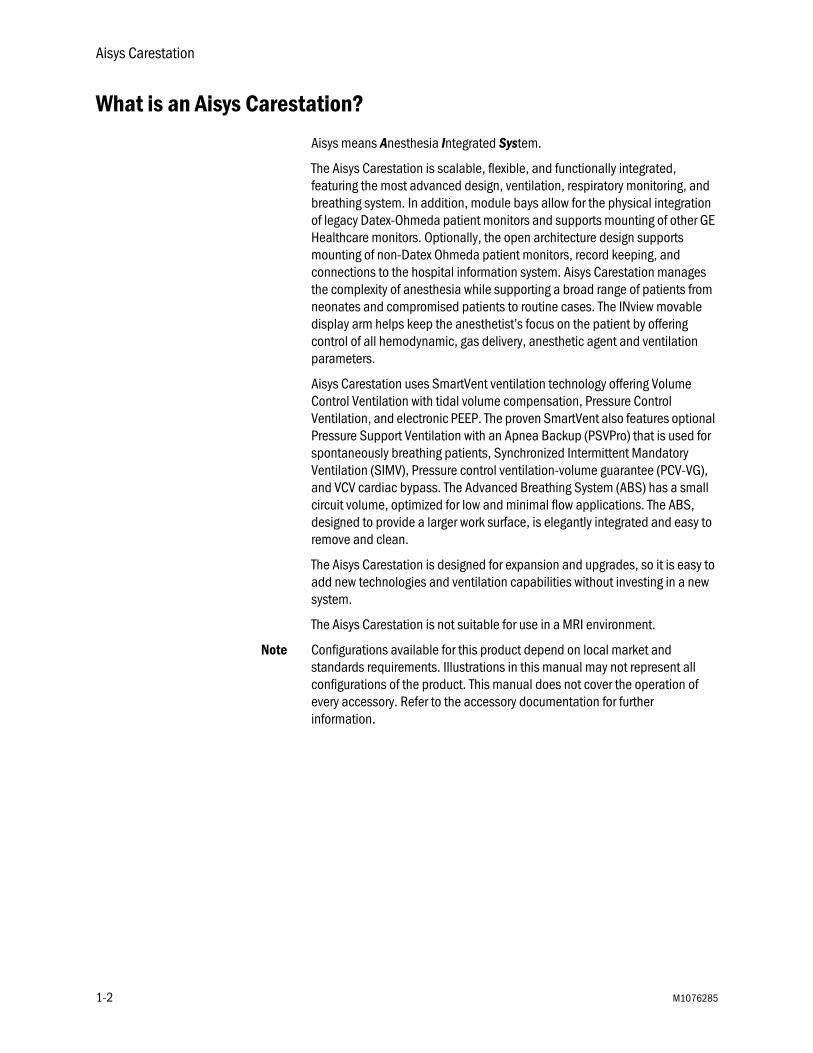
What is an Aisys Carestation?
Aisys means Anesthesia Integrated System.
The Aisys Carestation is scalable, flexible, and functionally integrated, featuring the most advanced design, ventilation, respiratory monitoring, and breathing system. In addition, module bays allow for the physical integration of legacy Datex-Ohmeda patient monitors and supports mounting of other GE Healthcare monitors. Optionally, the open architecture design supports mounting of non-Datex Ohmeda patient monitors, record keeping, and connections to the hospital information system. Aisys Carestation manages the complexity of anesthesia while supporting a broad range of patients from neonates and compromised patients to routine cases. The INview movable display arm helps keep the anesthetist’s focus on the patient by offering control of all hemodynamic, gas delivery, anesthetic agent and ventilation parameters.
Aisys Carestation uses SmartVent ventilation technology offering Volume Control Ventilation with tidal volume compensation, Pressure Control Ventilation, and electronic PEEP. The proven SmartVent also features optional Pressure Support Ventilation with an Apnea Backup (PSVPro) that is used for spontaneously breathing patients, Synchronized Intermittent Mandatory Ventilation (SIMV), Pressure control ventilation-volume guarantee (PCV-VG), and VCV cardiac bypass. The Advanced Breathing System (ABS) has a small circuit volume, optimized for low and minimal flow applications. The ABS, designed to provide a larger work surface, is elegantly integrated and easy to remove and clean.
The Aisys Carestation is designed for expansion and upgrades, so it is easy to add new technologies and ventilation capabilities without investing in a new system.
The Aisys Carestation is not suitable for use in a MRI environment.
Note Configurations available for this product depend on local market and standards requirements. Illustrations in this manual may not represent all configurations of the product. This manual does not cover the operation of every accessory. Refer to the accessory documentation for further information.
1-2 M1076285

1 Introduction
Figure 1-1 • Aisys Carestation
AB.7
5.10
0
M1076285 1-3

Aisys Carestation
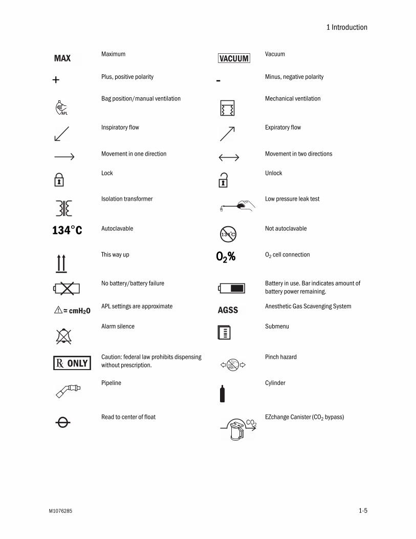
Symbols used in the manual or on the equipment
Symbols replace words on the equipment, on the display, or in Datex-Ohmeda manuals.
Warnings and Cautions tell you about dangerous conditions that can occur if you do not follow all instructions in this manual.
Warnings tell about a condition that can cause injury to the operator or the patient.
Cautions tell about a condition that can cause damage to the equipment. Read and follow all warnings and cautions.
On (power) Off (power)
Standby OOOO2222++++ O2 Flush button
Type BF equipment Type B equipment
Dangerous voltage Alternating current
Caution, ISO 7000-0434 Attention, refer to product instructions, IEC 60601-1
Electrical input Electrical output
Pneumatic inlet Pneumatic outlet
SN Serial number REF Stock number
Equipotential Lamp, lighting, illumination
Variability Variability in steps
Suction bottle outlet Vacuum inlet
1-4 M1076285
1 Introduction
Maximum Vacuum
+ Plus, positive polarity - Minus, negative polarity
Bag position/manual ventilation Mechanical ventilation
Inspiratory flow Expiratory flow
Movement in one direction Movement in two directions
Lock Unlock
Isolation transformer Low pressure leak test
134°C Autoclavable Not autoclavable
This way up OOOO2222%%%% O2 cell connection
No battery/battery failure Battery in use. Bar indicates amount of battery power remaining.
APL settings are approximate Anesthetic Gas Scavenging System
Alarm silence Submenu
Caution: federal law prohibits dispensing without prescription.
Pinch hazard
Pipeline Cylinder
Read to center of float EZchange Canister (CO2 bypass)
MAX VACUUM
AGSS
M1076285 1-5

Aisys Carestation
Systems with this mark agree with the European Council Directive (93/42/EEC) for Medical Devices when they are used as specified in their User’s Reference manuals. The xxxx is the certification number of the Notified Body used by Datex-Ohmeda’s Quality Systems.
Authorized representative in the European Community
Manufacturer
1-6 M1076285

1 Introduction
Typeface conventions used
Names of hard keys on the display and modules are written in bold typeface; for example, Normal Screen.
Menu items are written in bold italic typeface; for example, Vent Setup.
Messages that are displayed on the screen are enclosed in single quotes; for example, ‘Check sample gas out.’
When referring to different sections and other documents, the names are written in italic typeface and enclosed in double quotes; for example, “System Controls and Menus.”
Abbreviations
Abbreviation Definition
C
Compl Compliance
E
ET End-tidal concentration
EtCO2 End-tidal carbon dioxide
EtO2 End-tidal oxygen
F
F-V Flow-Volume loop
FI Fraction of inspired gas
FI-ET Difference between inspiratory and expiratory concentrations
FiO2 Fraction of inspired oxygen
I
I:E Inspiratory-expiratory ratio
Insp Pause Inspiratory pause time
M
MV Minute volume
MVexp Expired minute volume
MVinsp Inspired minute volume
O
O2 Oxygen
M1076285 1-7

Aisys Carestation
P
P-F Pressure-Flow loop
P-V Pressure-Volume loop
Pair Air supply pressure
Paux Auxiliary pressure
Paw Airway pressure
PCV Pressure controlled ventilation
PCV-VG Pressure controlled ventilation-volume guaranteed
PEEP Positive end expiratory pressure
PEEPe Extrinsic positive end expiratory pressure
Pexp Expiratory pressure
Pinsp Inspiratory pressure
Plimit High pressure limit
Pmax Maximum pressure
Pmean Mean pressure
PO2 Oxygen supply pressure
Ppeak Peak pressure
Pplat Plateau pressure
Psupp Support pressure
PSVPro Pressure supported ventilation with apnea backup
R
Rate Respiratory rate
Raw Airway resistance
RR Respiratory rate
S
SIMV-PC Synchronized intermittent mandatory ventilation-pressure controlled
SIMV-VC Synchronized intermittent mandatory ventilation-volume controlled
SIMV/PSV Synchronized intermittent mandatory ventilation/pressure supported ventilation
T
TV Tidal volume
TVexp Expired tidal volume
Abbreviation Definition
1-8 M1076285

1 Introduction
TVinsp Inspired tidal volume
V
VCO2 Carbon dioxide production
VCV Volume controlled ventilation
Vol Volume
Abbreviation Definition
M1076285 1-9

Aisys Carestation
1-10 M1076285
2 System Controls and Menus
In this section System overview . . . . . . . . . . . . . . . . . . . . . . . . . . . . . . . . . . . . . . . . . . . . . . . 2-2
Advanced breathing system (ABS) components . . . . . . . . . . . . . . . . . . . . . . 2-6
Display controls . . . . . . . . . . . . . . . . . . . . . . . . . . . . . . . . . . . . . . . . . . . . . . . 2-11
Anesthesia system display . . . . . . . . . . . . . . . . . . . . . . . . . . . . . . . . . . . . . . 2-12
Using menus . . . . . . . . . . . . . . . . . . . . . . . . . . . . . . . . . . . . . . . . . . . . . . . . . 2-14
M1076285 2-1

Aisys Carestation
System overviewWARNING Explosion hazard. Do not use this system with flammable
anesthetic agents.
Figure 2-1 • Front view*These items are described in further detail in the following table.
1. Airway module (optional) 9. O2 flush button*2. Datex-Ohmeda patient monitoring modules (optional) 10. System switch*3. Dovetail/GCX rails 11. Integrated suction (optional)*4. Light switch 12. Advanced breathing system5. Alternate O2 control* 13. Auxiliary O2 flow control (optional)*6. Mains indicator* 14. Aladin cassette and active bay7. Brake* 15. Anesthesia display8. Aladin cassette storage bay 16. Datex-Ohmeda patient monitoring display (optional)
2
34
56
8
9
10
11
12
13
14
15
AB.7
5.09
7
1
16
7
2-2 M1076285

2 System Controls and Menus
Item, Figure 2-1 Description
5 Alternate O2 control Alternate O2 control activates automatically in the case of certain failures or errors. It can also be activated manually by pushing the Alternate O2 control button if the display fails. Turn the knob counterclockwise to increase the flow. Turn the knob clockwise to decrease the flow. See “Alternate O2 Control” in the Operation section of this manual.
6 Mains indicator The mains indicator will come on when AC power is connected.7 Brake Push down to lock. Lift to release.
9 O2 flush button Push the O2 flush button to supply high flows of O2 to the breathing system.
10 System switch Set the switch to the On (||||) position to permit gas flow and to turn on the system.
11 Integrated suction Turn the switch to Max for full vacuum. Turn the switch to Off for no vacuum. Turn the switch to On for adjustable vacuum. When in adjustable vacuum, turn the knob clockwise to increase the vacuum and counterclockwise to decrease the vacuum.
13 Auxiliary O2 flow control Turn the knob counterclockwise to increase the flow. Turn the knob clockwise to decrease the flow.
M1076285 2-3

Aisys Carestation
Figure 2-2 • Rear view
1. Serial port 7. Mains inlet2. Collection bottle connection 8. System circuit breaker3. Cylinder wrench (key) storage 9. Equipotential stud4. Cylinder yoke 10. Outlet circuit breaker5. AGSS (Anesthesia Gas Scavenging System) 11. Isolated electrical outlet6. Pipeline connections
1
2
4
5
6
7
89
10
3
11
AB.7
5.04
6
2-4 M1076285

2 System Controls and Menus
Aladin cassettecontrols
The electronically controlled vaporizer consists of the internal electronic control unit and the Aladin agent cassette. See “Vaporizer” section for more information.
1. Handle with release trigger2. Lock3. Liquid level indicator4. Agent filling port
Figure 2-3 • Aladin2 cassette
1
2
34
AB.6
0.03
8
M1076285 2-5

Aisys Carestation
Advanced breathing system (ABS) components
Figure 2-4 • Advanced breathing system
*These items are described in further detail in the following table.
1. Airway module (optional) 8. Leak test plug2. Expiratory check valve 9. Manual bag port3. Inspiratory check valve 10. Breathing system release4. Inspiratory flow sensor* 11. Adjustable pressure-limiting (APL) valve*5. Expiratory flow sensor* 12. Bag/Vent switch*6. Absorber canister 13. Bellows assembly7. Absorber canister release*
1
2
3
4
5
6
7
8
10
9
13
1211
AB.7
5.09
8
2-6 M1076285

2 System Controls and Menus
Item, Figure 2-4 Description
4, 5 Flow sensor Flow sensors provide volume measurements for some monitoring functions and tidal volume delivery.
7 Absorber canister release
Push to remove the canister. This causes the breathing system to vent to the room (unless the EZchange Canister option is installed). Be sure to hold the canister by the handle before releasing the canister.
11 APL valve Adjusts breathing system pressure limit during manual ventilation. The scale shows approximate pressures. Above 30 cmH2O, the knob will click as it turns.
12 Bag/Vent switch Selects between manual ventilation (bag) or mechanical ventilation (ventilator).
20
30
70MIN
M1076285 2-7
Aisys Carestation
Optional ABScomponents
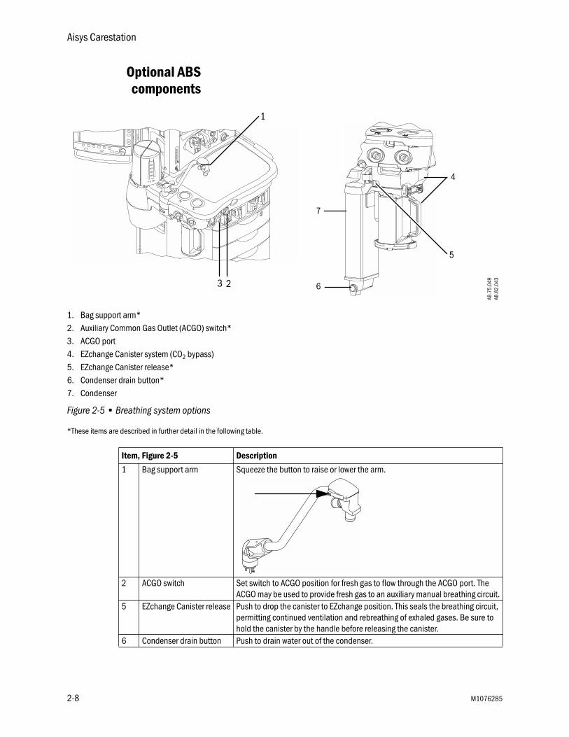
1. Bag support arm*2. Auxiliary Common Gas Outlet (ACGO) switch*3. ACGO port4. EZchange Canister system (CO2 bypass)5. EZchange Canister release*6. Condenser drain button*7. Condenser
Figure 2-5 • Breathing system options
*These items are described in further detail in the following table.
Item, Figure 2-5 Description
1 Bag support arm Squeeze the button to raise or lower the arm.
2 ACGO switch Set switch to ACGO position for fresh gas to flow through the ACGO port. The ACGO may be used to provide fresh gas to an auxiliary manual breathing circuit.
5 EZchange Canister release Push to drop the canister to EZchange position. This seals the breathing circuit, permitting continued ventilation and rebreathing of exhaled gases. Be sure to hold the canister by the handle before releasing the canister.
6 Condenser drain button Push to drain water out of the condenser.
1
23
AB.7
5.04
9AB
.82.
043
4
6
7
5
2-8 M1076285

2 System Controls and Menus
Non-circle circuit Fresh gas flow is diverted around the inspiratory check valve and out through the inspiratory port when non-circle ventilation is selected. This fresh gas source may be used with circuits without CO2 absorbent capability (e.g., Mapleson variants). Mechanical ventilation is not available when using the non-circle circuit. Tidal volume monitoring is not available.
O2 monitoring of fresh gas is available automatically when the non-circle circuit is selected if the system has the airway module option or the O2 cell monitoring option.
Fresh gas oxygen concentration is displayed on the screen. Set the alarm limits appropriately. Note that fresh gas oxygen concentration may not reflect FiO2 when using these types of circuits. Use an external O2 monitor when using a rebreathing circuit with the non-circle circuit.
Systems with both an airway module and an O2 cell will display the circuit O2 value obtained from the airway module.
Do not use an external ventilator when using the non-circle circuit. Do not use the non-circle circuit to drive external ventilators or for jet ventilation.
WARNING The maximum pressure at the non-circle circuit can be up to 27 kPa (4 psi). Use a breathing circuit with pressure relief.
ACGO (optional) Fresh gas flow is directed through the Auxiliary Common Gas Outlet (ACGO) on the front of the machine when the ACGO switch is in the ACGO position. Mechanical ventilation is not available when operating an auxiliary manual breathing circuit with fresh gas from the ACGO. The Bag/Vent switch, APL valve, and bag arm are not part of the external circuit. Volume and pressure monitoring are not available.
O2 monitoring of fresh gas is available automatically when the ACGO is selected if the system has the airway module option or the O2 cell monitoring option. A sample of the fresh gas is diverted to the O2 cell in the breathing system. The sample flow to the O2 cell is dependent on the pressure in the external circuit. The sample flow reduces the fresh gas flow rate to the auxiliary breathing circuit equal to the amount diverted to the O2 cell.
Fresh gas oxygen concentration is displayed on the screen. Set the alarm limits appropriately. Note that fresh gas oxygen concentration may not reflect FiO2 during spontaneous breathing or in rebreathing circuits. Use an external O2 monitor if using a rebreathing circuit on ACGO.
Systems with both an airway module and an O2 cell will display the circuit O2 value obtained from the airway module.
Do not use an external ventilator on the ACGO. Do not use the ACGO to drive external ventilators or for jet ventilation.
WARNING The maximum pressure at the ACGO can be up to 55 kPa (8 psi). Use a breathing circuit with pressure relief.
M1076285 2-9

Aisys Carestation
Scavenging the ACGOsample flow
A sample of the fresh gas is diverted to the airway module or the O2 cell in the breathing system. If an auxiliary manual breathing circuit is to be used with N2O or volatile anesthetics, this sample flow should be scavenged.
1. Attach a circle breathing circuit to the inspiratory and expiratory ports. Occlude the circle circuit by connecting the Y-piece to the plug located to the rear of the expiratory port.
2. Check for clinically correct settings. Set the Bag/Vent switch to mechanical ventilation mode. (Mechanical ventilation will not start when ACGO is selected.) Alternatively, set the Bag/Vent switch to the bag mode, set the APL valve to MIN, and attach a bag.
3. The bellows, or bag, will fill slowly with the fresh gas sample flow and then spill to the AGSS.
Scavenging from anauxiliary manualbreathing circuit
Scavenge the exhaust if an auxiliary manual breathing circuit is used with N2O or volatile anesthetics.
An auxiliary inlet is available for active and passive AGSS units. It provides a female connection with 30 mm - 30 mm male connector (or a 30 mm -19 mm male connector) into the auxiliary port under the breathing system. Do not use these connectors as an outlet for exhaust flow.
The auxiliary inlet is a convenience inlet to the air brake of active AGSS units. There is a reservoir to capture exhaust flows higher than the extract flow.
A separate exhaust hose is needed from the auxiliary manual breathing circuit to the disposal point for all AGSS units.
Scavenging a gasmonitor sample flow
Sample gas from a gas monitor can be scavenged using the sample gas return port or the AGSS. To scavenge from a gas monitor using the sample gas return port, connect the tubing from the monitor to the sample gas return port. To scavenge from a gas monitor using the AGSS, connect tubing from the monitor to the male luer inlet on the bottom of the AGSS underneath the breathing system.
2-10 M1076285

2 System Controls and Menus
Display controls
Figure 2-6 • Display controls
1
3
2
5
2
AB.7
5.09
9
6
4
7
1. Silence Alarms key Push to silence any active, silenceable high and medium priority alarms or to suspend/acknowledge any non-active medium or high priority alarms. Alarm is silenced for 120 seconds or alarm is suspended for 90 seconds.
2. Menu keys Push to show corresponding menu.3. ComWheel Push to select a menu item or confirm a setting. Turn clockwise or
counterclockwise to scroll menu items or change settings.4. Normal Screen key Push to remove all menus from the screen.5. Quick keys Push to change corresponding gas setting or ventilator setting. Turn the
ComWheel to make a change. Push the ComWheel to activate the change.6. Timer keys Push to start or stop the timer. Push to reset the timer back to zero.7. MV/TV Alarms key Push to turn off the MV and TV alarms. Push again to turn the MV and TV
alarms back on.
M1076285 2-11

Aisys Carestation
Anesthesia system display
1. Electronic gas flow indicators2. Alarm silence countdown3. Alarm message fields4. Waveform fields5. General message field or timer field6. Clock7. Battery indicator field8. Measured values field9. Pipeline and cylinder supply or respiratory data10. Ventilator settings11. Ventilation mode12. Gas and agent settings
Figure 2-7 • Normal view
2 3 4 5
8
910 AB.7
5.00
6
6
12
1
11
7
2-12 M1076285

2 System Controls and Menus
When a menu key is selected, the menu field overlays the gas flow indicators and the waveform fields start at the right edge of the menu.
1. Menu2. Waveform fields
Figure 2-8 • Menu view
1
2
AB.7
5.00
7
M1076285 2-13

Aisys Carestation
Using menus
Push a menu key to display the corresponding menu. Use the ComWheel to navigate through the menu.
1. Menu title2. Present selection3. Adjustment window4. Indicates submenu5. Short instructions6. Menu selections
Figure 2-9 • Example menu
1
2
3
4
5
6
AB.9
1.00
7
2-14 M1076285

2 System Controls and Menus
1. Push the menu key to display the corresponding menu.
2. Turn the ComWheel counterclockwise to highlight the next menu item. Turn the ComWheel clockwise to highlight the previous menu item.
AB.9
1.00
4AB
.91.
005
M1076285 2-15

Aisys Carestation
3. Push the ComWheel to enter the adjustment window or a submenu.
4. Turn the ComWheel clockwise or counterclockwise to highlight the desired selection.
AB.9
1.00
6AB
.91.
007
2-16 M1076285

2 System Controls and Menus
5. Push the ComWheel to confirm the selection.
6. Select Normal Screen or push the Normal Screen key to exit the menu and return to the normal monitoring display. (Select Previous Menu to return to the last displayed menu, if available.)
AB.9
1.00
8AB
.91.
009
M1076285 2-17

Aisys Carestation
2-18 M1076285

3 Operation
WARNING Ventilator alarms indicate potential hazard conditions. All alarms that occur should be investigated to help ensure adequate patient safety.
w Maintain sufficient fresh gas flow when using sevoflurane.
w Desiccated (dehydrated) absorbent material may produce dangerous chemical reactions when exposed to inhalation anesthetics. Adequate precautions should be taken to ensure that absorbent does not dry out. Turn off all gases when finished using the system.
In this section Turning on the system . . . . . . . . . . . . . . . . . . . . . . . . . . . . . . . . . . . . . . . . . . . 3-2
Start gas flow (start case) . . . . . . . . . . . . . . . . . . . . . . . . . . . . . . . . . . . . . . . . 3-3
End case . . . . . . . . . . . . . . . . . . . . . . . . . . . . . . . . . . . . . . . . . . . . . . . . . . . . . 3-4
Ventilator setup . . . . . . . . . . . . . . . . . . . . . . . . . . . . . . . . . . . . . . . . . . . . . . . . 3-5
Gas setup . . . . . . . . . . . . . . . . . . . . . . . . . . . . . . . . . . . . . . . . . . . . . . . . . . . . . 3-7
Spirometry setup . . . . . . . . . . . . . . . . . . . . . . . . . . . . . . . . . . . . . . . . . . . . . . . 3-8
Viewing spirometry loops . . . . . . . . . . . . . . . . . . . . . . . . . . . . . . . . . . . . . . . 3-10
Screen configuration . . . . . . . . . . . . . . . . . . . . . . . . . . . . . . . . . . . . . . . . . . . 3-11
Alarm setup . . . . . . . . . . . . . . . . . . . . . . . . . . . . . . . . . . . . . . . . . . . . . . . . . . 3-12
Viewing trends . . . . . . . . . . . . . . . . . . . . . . . . . . . . . . . . . . . . . . . . . . . . . . . . 3-13
Alternate O2 control . . . . . . . . . . . . . . . . . . . . . . . . . . . . . . . . . . . . . . . . . . . . 3-14
EZchange Canister (optional) . . . . . . . . . . . . . . . . . . . . . . . . . . . . . . . . . . . . 3-15
Condenser (optional) . . . . . . . . . . . . . . . . . . . . . . . . . . . . . . . . . . . . . . . . . . 3-16
Passive AGSS (optional) . . . . . . . . . . . . . . . . . . . . . . . . . . . . . . . . . . . . . . . . 3-17
Active AGSS (optional) . . . . . . . . . . . . . . . . . . . . . . . . . . . . . . . . . . . . . . . . . 3-18
M1076285 3-1

Aisys Carestation
Turning on the system
1. Plug the power cord into a electrical outlet. Make sure the system circuit breaker is on.
• The mains indicator will come on when AC power is connected. Battery is charging if not already fully charged.
1. System switch2. Mains indicator
Figure 3-1 • Mains indicator and system switch
2. Check that the breathing system is properly connected.
CAUTION Do not turn on the system with the right-hand (inspiratory) port plugged.
3. Turn the System switch to On.
• The display shows the power-up screen.
• The system does a series of automated self tests.
4. Perform a Machine Check before the first case of the day. Perform the Individual Checks as needed before each case. See sections “Preoperative Checkout” and “Preoperative Tests.”
12
AB.7
5.05
2
3-2 M1076285

3 Operation
Start gas flow (start case)
Using quick start To quickly start a case using the defaults shown on the Start Case menu, press any quick key once.
Using default settings 1. Set the Bag/Vent switch to Bag.
2. Push the Start/End Case key to go to the Start Case menu or select Start Case from the Checkout menu.
3. Select the ventilator and alarm settings from Defaults, Last Case, or Patient Weight.
4. Select Other Gas, and select a balance gas to use with O2.
5. Select Circuit, and select Circle circuit or Non-Circle circuit.
6. To start a case using the ventilator and alarm settings selected, select Start Case Now. Gas flow starts.
Presetting ventilatorand alarm settings
1. Set the Bag/Vent switch to Bag.
2. Push the Start/End Case key to go to the Start Case menu or select Start Case from the Checkout menu.
3. Select the ventilator and alarm settings from Defaults, Last Case, or Patient Weight.
4. Select Other Gas, and select a balance gas to use with O2.
5. Select Circuit, and select Circle circuit or Non-Circle circuit.
6. To change the alarm settings before starting a case:
• Push the Alarm Setup key.
• To change the alarm settings, select Adjust Settings.
— Change the settings.
— Select Back.
• Make any other changes to the alarm setup.
• To start a case, select Start Case Now. Gas flow starts.
• To change the ventilator settings, select the Vent Setup key. Follow the instructions in the next steps to change the ventilator settings.
Note If changes are only made to the alarm settings and no changes are made to the ventilator settings, the ventilator settings are set to the selection made on the Start Case menu: Defaults, Last Case, or Patient Weight.
M1076285 3-3
Aisys Carestation
7. To change ventilator settings for the selected mode before starting a case:
• Push the Vent Setup key.
• Select Adjust Settings.
• Change the settings.
• Select Exit.
• Select Start Case Now. Gas flow starts.
8. To change the ventilation mode before starting a case:
• Push the Vent Setup key.
• Select the desired mode.
• Select Confirm or adjust the settings and select Confirm.
• Select Start Case Now. Gas flow starts.
Note If changes are made only to the ventilator settings and no changes are made to the alarm settings, the alarm settings are set to the selection made in the Start Case menu: Defaults, Last Case, or Patient Weight.
End case
1. Set the Bag/Vent switch to Bag.
2. Push the Start/End Case key.
3. Select End Case Now to put the system in standby. (Stops gas flow and ventilator alarms. Stops alarms on battery-backup patient monitors.)
3-4 M1076285

3 Operation
Ventilator setup
The system has six modes of mechanical ventilation:
• volume control (VCV).
• pressure control (PCV) (optional).
• synchronized intermittent mandatory/pressure support (SIMV/PSV) (optional).
• pressure support (PSVPro) (optional).
• synchronized intermittent mandatory-pressure control (SIMV-PC) (optional).
• pressure control ventilation-volume guarantee (PCV-VG) (optional).
WARNING Most anesthetic agents will cause patients to have reduced ventilatory responses to carbon dioxide and to hypoxemia. Therefore, triggered modes of ventilation may not produce adequate ventilation.
w The use of neuromuscular blocking agents will reduce the patient’s breathing response, which will interfere with triggering.
Note Refer to the “Specifications and Theory of Operation” section in Part 2 of the User’s Reference manual for more information on ventilation modes.
Using quick keys The three main ventilator settings for each mode can easily be changed using the ventilator quick keys.
1. Push a ventilator quick key to select the corresponding ventilator setting.
2. Turn the ComWheel to make a change.
3. Push the ComWheel to activate (confirm) the change.
Using Vent Setup menu 1. Push the Vent Setup key.
• An arrow to the right of the mode indicates the current mode.
• Adjust Settings is selected by default.
2. Push the ComWheel to enter the adjustment window for the selected mode.
3. Use the ComWheel to navigate through the adjustment window and to change a value.
4. Push the ComWheel to activate the change.
5. Push the Normal Screen key or select Exit.
M1076285 3-5
Aisys Carestation
Changing ventilatormodes and settings
1. Push the Vent Setup key.
2. Select the mode and push the ComWheel to enter the adjustment window.
3. Use the ComWheel to navigate through the adjustment window and to change a value.
4. Confirm the settings to activate the mode.
Manual ventilationcardiac bypass
Manual ventilation cardiac bypass suspends alarms for patients on cardiac bypass when the ventilator is not mechanically ventilating. The volume, apnea, PEEP, low agent, low CO2, and respiratory rate alarms are suspended. The alarms are enabled when cardiac bypass is turned off or mechanical ventilation is started.
1. Set the Bag/Vent switch to Bag.
2. Push the Main Menu key.
3. Set Cardiac Bypass to On.
• The general message ‘Cardiac Bypass’ shows in the waveforms and in the general message field when passive cardiac bypass is active.
VCV cardiac bypass(optional)
Systems equipped with VCV cardiac bypass and enabled in the Super User menu can use the cardiac bypass feature during mechanical ventilation while in VCV mode. Only VCV mode is available while using VCV cardiac bypass. The volume, apnea, PEEP, low agent, low CO2, and respiratory rate alarms are suspended. The alarms are enabled when VCV cardiac bypass is turned off or mechanical ventilation is stopped.
1. Start mechanical ventilation in VCV mode.
2. Push the Main Menu key.
3. Set Cardiac Bypass to On.
• PEEP is set to 5 cmH2O and TV is set to 170 ml when the VCV setting for TV is greater than 170 ml.
• The general message ‘VCV Cardiac Bypass’ shows in the waveforms and in the general message field when VCV cardiac bypass is active.
3-6 M1076285

3 Operation
Gas setup
Using quick keys The O2%, total flow, and agent concentration can easily be changed using the gas quick keys.
1. Push a gas quick key to select the corresponding gas setting.
2. Turn the ComWheel to make a change.
3. Push the ComWheel to activate (confirm) the change.
Using Gas Setup menu 1. Push the Gas Setup key.
• An arrow to the right of the balance gas indicates the gas currently being used with O2.
• Adjust Settings is selected by default.
2. Push the ComWheel to enter the adjustment window.
3. Use the ComWheel to navigate through the adjustment window and change a value.
4. Push the ComWheel to activate the change.
5. Push the Normal Screen key or select Exit.
Changing gas andsettings
1. Push the Gas Setup key.
2. Select the balance gas to use with O2 and push the ComWheel to enter the adjustment window.
3. Use the ComWheel to navigate through the adjustment window and change a value.
4. Push the ComWheel to activate the change.
Changing circuit type 1. Push the Gas Setup key.
• An arrow to the right of the circuit type indicates the circuit currently in use.
2. Use the ComWheel to select Circle circuit or Non-Circle circuit and enter the adjustment window.
3. Confirm or change and confirm the O2 and Total Flow settings.
4. Push the Normal Screen key or select Exit.
M1076285 3-7

Aisys Carestation
Spirometry setup
Push the Spirometry key and select Spiro Setup to access the Spirometry Setup menu. Use the Spirometry Setup menu to:
• Set the patient and sensor type.
• Select a data source.
• View, save, and erase spirometry loops; and to set the loop scaling.
• Change the volume shown on the spirometry split screen to MVexp or TVexp.
• Set split-screen view.
• For quick access to the Paw and MVexp alarm limits.
Note The Spirometry Setup menu is also accessible through Main Menu - Parameter Setup - Spirometry Setup.
Setting patient andsensor type
Patient and sensor type refer to the style of airway adapter used with the airway module. If spirometry data is obtained from the airway module, ensure that the sensor type matches the airway adapter used. If an airway module is not installed, Patient and sensor type is not selectable.
If the sensor type is not set correctly, the information displayed may not be accurate.
1. Push the Spirometry key.
2. Select Spiro Setup - Patient and Sensor Type.
3. Select Adult or Pedi depending on the sensor used.
• Adult refers to the D-lite sensor.
• Pedi refers to the Pedi-lite sensor.
3-8 M1076285

3 Operation
Selecting a data source Several monitoring parameters can be obtained from the ventilator or the airway module. Information that is retrieved from the airway module is identified with the module data indicator. Refer to the “Airway Modules” for more information.
Figure 3-2 • Airway module data indicator
1. Push the Spirometry key.
2. Select Spiro Setup - Data Source.
3. Select Patient or Vent as the primary source for information.
• If Patient is selected, the airway module will be the first source for information if a D-lite or Pedi-lite sensor is properly connected. If the sensor is not properly connected, but the airway module is installed the waveform data is not displayed. If information is not available through the airway module, information will come from the internal ventilator sensors.
• If Vent is selected, the internal sensors of the ventilator will be the first source for information.
Setting spirometry splitscreen
Spirometry loops can be viewed alongside the waveforms on the normal screen. To set up the spirometry split screen:
1. Push the Spirometry key.
2. Select Spiro Setup.
3. Select Split Screen - Spiro.
4. Push the Normal Screen key.
Setting loop type Spirometry loop type shown in the spirometry split screen and in the spirometry split screen view can be set in the Spirometry Setup menu.
1. Push the Spirometry key.
2. Select Spiro Setup - Loop Type and choose the desired view.
Note The loop type can also be set in the Spirometry Menu. The Spirometry Setup menu can also be accessed through Main Menu - Parameter Setup - Spirometry Setup.
M1076285 3-9
Aisys Carestation
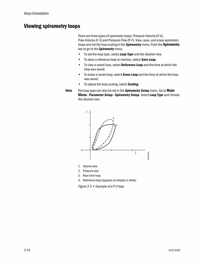
Viewing spirometry loops
There are three types of spirometry loops: Pressure-Volume (P-V), Flow-Volume (F-V) and Pressure-Flow (P-F). View, save, and erase spirometry loops and set the loop scaling in the Spirometry menu. Push the Spirometry key to go to the Spirometry menu.
• To set the loop type, select Loop Type and the desired view.
• To store a reference loop to memory, select Save Loop.
• To view a saved loop, select Reference Loop and the time at which the loop was saved.
• To erase a saved loop, select Erase Loop and the time at which the loop was saved.
• To adjust the loop scaling, select Scaling.
Note The loop type can also be set in the Spirometry Setup menu. Go to Main Menu - Parameter Setup - Spirometry Setup. Select Loop Type and choose the desired view.
1. Volume axis2. Pressure axis3. Real-time loop4. Reference loop (appears on display in white)
Figure 3-3 • Example of a P-V loop
2
1
4
3
AB.9
8.03
9
3-10 M1076285

3 Operation
Screen configuration
Waveform, fresh gas control style, split screen, sweep speed, time and date, and brightness are adjusted in the Screen Setup menu. The top waveform is fixed at Paw. The center waveform can be adjusted to show agent or flow, or it can be turned off. The bottom waveform can be set to show CO2, or it can be turned off. To change the display:
1. Push the Main Menu key.
2. Select Screen Setup.
3. Select the field to change, and make the change.
4. Push the Normal Screen key or select Previous Menu.
Split screen Gas and agent delivery, trends, spirometry loops, a metabolics chart, or a paw gauge can be shown as a split screen alongside the waveforms on the normal screen. Split screen settings cannot be saved as defaults. To change the normal screen to show a split screen:
1. Push the Main Menu key.
2. Select Screen Setup - Split Screen.
3. Select the desired view.
4. Push the Normal Screen key or select Previous Menu.
Setting gas controlsand screen
configuration
There are two ways to configure gas controls: O2%/total flow and individual gas flow. The Super User selects the configuration or can allow the user to select the configuration.
Selecting O2 shows O2% as the first quick key and total flow l/min as the second quick key. The gas control/screen configuration adjusts the balance automatically once the user changes either the O2% or the total flow is changed.
Selecting Flow shows balance gas l/min as the first quick key and 02 l/min as the second quick key. This gas control/screen configuration allows individual control of the gasses.
1. Push the Main Menu key.
2. Select Screen Setup - Fresh Gas Controls.
3. Select the desired view.
4. Push the Normal Screen key or select Previous Menu.
M1076285 3-11

Aisys Carestation
Alarm setup
Alarm limits, alarm volume, and other alarm settings are adjusted in the Alarm Setup menu. Alarm history is also accessed through this menu. Selecting Default Limits loads the default settings as set by the Super User or the factory defaults if no Super User settings have been entered. Setting Leak Audio to Off silences audio alarms for small leaks.
Setting alarm limits 1. Push the Alarms Setup key.
2. Select Adjust Settings.
3. Scroll to the desired alarm.
4. Select alarm limit and change the value.
5. Push the Normal Screen key or select Back.
MV/TV Alarms The MV and TV alarms can be turned off. When the volume alarms are disabled, ‘MV/TV alarms Off’ appears in the general message field. If the MV and TV alarms are set to Off during manual ventilation, the alarms remain off until the Bag/Vent switch is set to ventilator or the MV/TV Alarms is set to On.
1. Push the Alarm Setup key.
2. Select MV/TV Alarms and set to Off.
CO2 Audio Set CO2 Audio to Off to silence the audio alarms for ‘Apnea’ CO2 and ‘ETCO2 low’ when the Bag/Vent switch is set to bag or when the respiratory rate setting is greater than 60 during mechanical ventilation. The visual alarms for ‘Apnea’ and for ‘ETCO2 low’ are not affected. The audio alarms remain off until the CO2 Audio is set to On or the respiratory is less than or equal to 60 during mechanical ventilation.
1. Push the Alarm Setup key.
2. Select CO2 Audio and set to Off.
Auto MV Limit MV alarm limits can be calculated automatically for mechanical ventilation when in VCV mode. Set Auto MV Limit to On for automatic calculations of the MV alarm limits. The MV alarm limits continue to be automatically calculated until Auto MV Limit is set to Off or until an MV alarm limit is manually adjusted during mechanical ventilation.
If the automatic calculation of the low or high minute volume alarm limit exceeds the allowable limit, the minimum or maximum alarm limit is used.
1. Push the Alarm Setup key.
2. Select Auto MV Limit and set to On.
3-12 M1076285

3 Operation
Viewing trends
There are three views for patient trends: measured (numerical), settings, and graphical. Trend information is saved every one minute for the most recent 24 hours.
1. Push Trends.
2. Select the desired view.
• An arrow indicates the current trend view.
3. Select Cursor to scroll through the current trend view.
4. Push the ComWheel to return the highlight to Cursor.
5. Select Next Page to view additional parameters.
6. Push the Normal Screen key or select Previous Menu.
M1076285 3-13

Aisys Carestation
Alternate O2 control
WARNING The Alternate O2 control is not an auxiliary source of O2.
Alternate O2 control delivers agent and O2 through an independent pneumatic path to the selected patient circuit and is connected to the system O2 supply. Alternate O2 control activates automatically in the case of certain failures or errors. It can also be activated manually. O2 flow is 0.5 l/min to 10 l/min as indicated on the flow tube.
WARNING When Alternate O2 control is enabled, flow from the electronic mixer is stopped and the agent concentration is set to off. O2 is flowing through the Alternate O2 control to the breathing system. To activate anesthetic agent flow to the breathing system, set the agent to the desired concentration.
The agent delivery cannot be activated in the case of certain electronic or agent delivery failures. The Agent quick key will be blank if agent delivery is unavailable.
The Alternate O2 control is available approximately 20 seconds after the system is turned on. The minimum flow can be preset to 0.5 to 10 l/min.
1. Push the Alternate O2 ON/OFF button.
2. The O2 flow is indicated on the flow tube.
3. Use the flow control to adjust the O2 flow.
4. Set the agent to the desired concentration.
1. ON/OFF button2. Flow tube3. Flow control
Figure 3-4 • Alternate O2 control
1
2
3
3-14 M1076285

3 Operation
EZchange Canister (optional)
Push the absorber canister release to activate the EZchange Canister mode. The canister will swing down to the EZchange position. The EZchange Canister mode seals the breathing circuit when the canister holder is down. This permits continued ventilation and rebreathing of exhaled gases while easily replacing the absorber canister.
Systems with EZchange Canister have the following label on the canister holder. When the system is in EZchange position, the message ‘CO2 Absorber Out of Circuit’ will be shown in the waveform area on the anesthesia display.
To return to absorber mode, reinsert the canister into the holder and push the canister back up and snap it into absorber position. When the canister is in the absorber position, the exhaled gas flows through the absorber, removing CO2.
Note Check the absorber canister to ensure it has side rails. If the canister does not have side rails, it will not work on the EZchange Canister holder.
AB.8
2.04
2AB
.74p
043
M1076285 3-15
Aisys Carestation
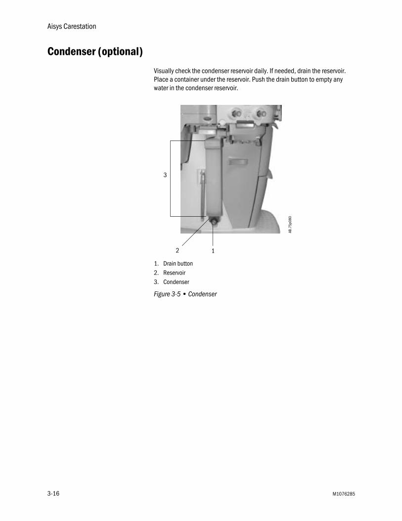
Condenser (optional)
Visually check the condenser reservoir daily. If needed, drain the reservoir. Place a container under the reservoir. Push the drain button to empty any water in the condenser reservoir.
1. Drain button2. Reservoir3. Condenser
Figure 3-5 • CondenserAB
.75p
080
12
3
3-16 M1076285

3 Operation
Passive AGSS (optional)
WARNING Always verify the proper operation of any gas scavenging system; ensure the scavenging system is not occluded.
The passive AGSS (Anesthesia Gas Scavenging System) contains both positive and negative pressure relief valves to protect the breathing system and the patient. The outlet is a 30-mm connector on the bottom of the receiver.
There is also a connector that may be used for scavenging the sample from a gas monitor. The male luer inlet connection is located near the 30-mm connector.
Passive AGSS is intended primarily for use in operating room environments which have no active gas extraction system for waste gas disposal. The disposal system generally consists of large diameter tubing directly linking the passive AGSS with the building exterior. The tubing should be as large in diameter and as short as possible for the particular application.
Passive AGSS may also be used with a non-recirculating facility ventilation system for waste gas disposal. The tubing connection from passive AGSS to the non-recirculating facility ventilation system should be an open connection, essentially at atmospheric pressure, such as to an exhaust grill.
M1076285 3-17

Aisys Carestation
Active AGSS (optional)
WARNING Always verify the proper operation of any gas scavenging system; ensure the scavenging system is not occluded.
There are several versions of the optional active AGSS (Anesthesia Gas Scavenging System) available depending on the hospital’s type of waste gas disposal system.
Each version has a two-liter reservoir to capture peak exhaust flows that briefly exceed the extract flow. The disposal system normally entrains room air through an air brake (located in a receiver underneath the breathing system), but will spill from this port during extended periods of high exhaust flow. Its effectiveness is limited by the extract flow of the particular active AGSS device.
• The active low flow system is for use with high vacuum disposal systems. It requires a vacuum system capable of a continuous nominal flow of 36 l/min and 300 mmHg (12 inHg) or greater vacuum pressure. A flow indicator on the system indicates when the unit is in operation.
• The active high flow system is for use with low vacuum (blower type) disposal systems. This requires a system capable of providing a continuous nominal flow of 50 l/min. A flow indicator on the system indicates when the unit is in operation.
• Another version is the active adjustable flow. It provides the capability to adjust the flow with a needle valve (located in a receiver underneath the breathing system) and a visual indicator bag which should be properly inflated. It requires a vacuum system capable of a continuous nominal flow of 36 l/min and 300 mmHg (12 inHg) or greater vacuum pressure. A flow indicator on the system indicates when the unit is in operation.
• The active low flow system with a 12.7 mm hose barb connector is for use with low vacuum disposal system. It requires an external Venturi system with flowmeter and 36 l/min extract flow.
• The active low flow system with a 25 mm barb connector is for use with low vacuum disposal systems. It requires an external venturi/ejector system with 36 l/min extract flow. A flow indicator on the system indicates when the unit is in operation.
• The active low flow system with 30 mm ISO taper is for use with low vacuum disposal systems. It requires an external venturi/ejector system with 36 l/min extract flow. A flow indicator on the system indicates when the unit is in operation.
3-18 M1076285
3 Operation
Connecting activeAGSS with a flow
indicator
To use the optional active AGSS on a system that has a flow indicator, connect it as follows.
1. Connect the proper hose to the AGSS outlet connector on the bottom of the AGSS underneath the breathing system. Attach the other end to the hospital disposal system.
2. With the AGSS operating, verify that the flow indicator ball on the flow indicator rises to the green zone, indicating adequate flow.
Note The ball in the upper red zone indicates excessively high extraction flow. The ball in the lower red zone indicates extraction flow rate is too low or a blocked filter.
3. Complete the tests in the “Preoperative Tests” section of this manual.
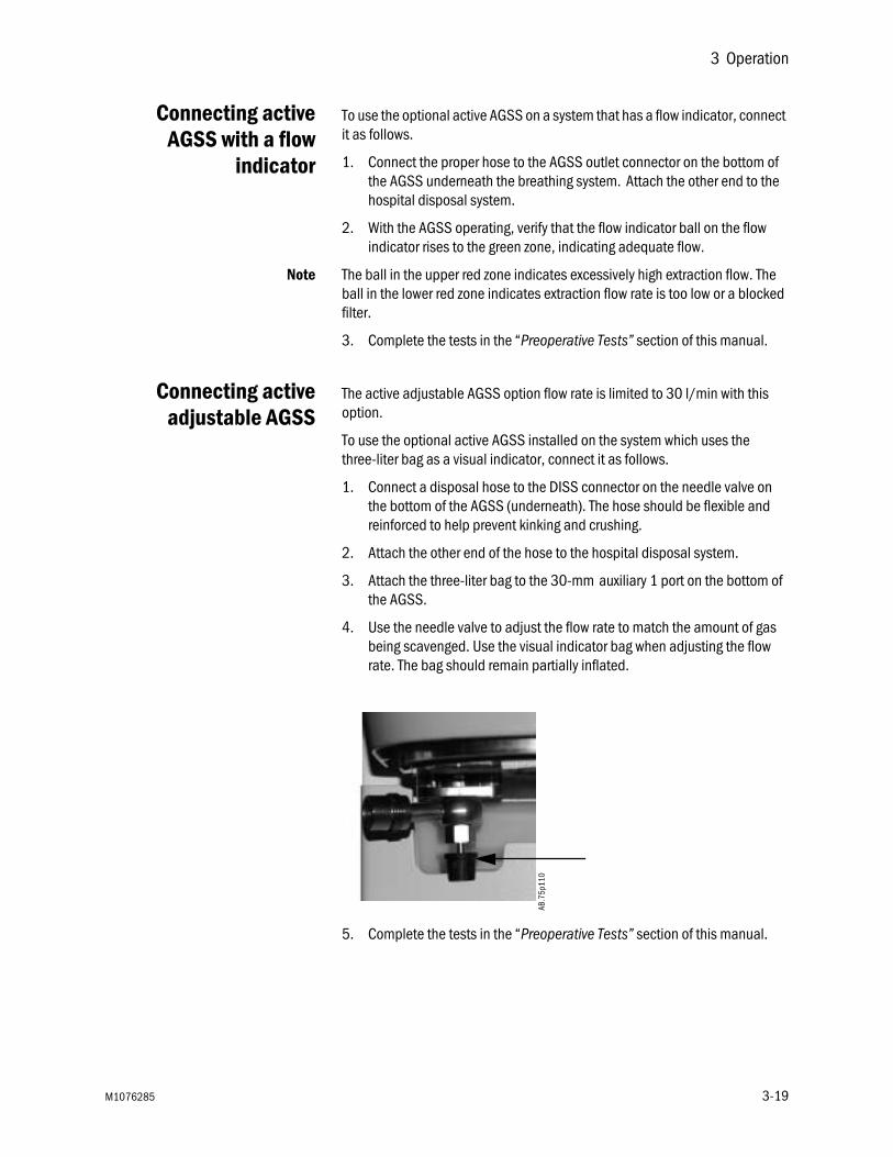
Connecting activeadjustable AGSS
The active adjustable AGSS option flow rate is limited to 30 l/min with this option.
To use the optional active AGSS installed on the system which uses the three-liter bag as a visual indicator, connect it as follows.
1. Connect a disposal hose to the DISS connector on the needle valve on the bottom of the AGSS (underneath). The hose should be flexible and reinforced to help prevent kinking and crushing.
2. Attach the other end of the hose to the hospital disposal system.
3. Attach the three-liter bag to the 30-mm auxiliary 1 port on the bottom of the AGSS.
4. Use the needle valve to adjust the flow rate to match the amount of gas being scavenged. Use the visual indicator bag when adjusting the flow rate. The bag should remain partially inflated.
5. Complete the tests in the “Preoperative Tests” section of this manual.
AB.7
5p11
0
M1076285 3-19

Aisys Carestation
3-20 M1076285

4 Preoperative Checkout
WARNING Read each component’s User’s Reference manual and understand the following before using this system:
• All system connections.
• All warnings and cautions.
• How to use each system component.
• How to test each system component.
Before using the system:
• Complete all of the tests in this section.
• Test all other system components.
If a test fails, do not use the equipment. Have a Datex-Ohmeda trained service representative repair the equipment.
In this section Every day before your first patient . . . . . . . . . . . . . . . . . . . . . . . . . . . . . . . . . 4-2
Before every patient . . . . . . . . . . . . . . . . . . . . . . . . . . . . . . . . . . . . . . . . . . . . 4-3
M1076285 4-1

Aisys Carestation
Every day before your first patient
" Check that necessary emergency equipment is available and in good condition.
" Check that the equipment is not damaged and that components are correctly attached.
" Check that pipeline gas supplies are connected and cylinders are installed.
" Check that the amount of liquid agent in the cassette is adequate, and install the agent casette into the active bay. The casette is properly inserted when the agent is identified on the display.
" Check that the breathing circuit is correctly connected, not damaged, and the breathing system contains sufficient absorbent.
" Turn the System switch to On.
" Connect scavenging and verify operation.
" Calibrate the flow sensors.
" Do a Machine Check in the Checkout menu.
" To check additional Aladin cassettes, do an Agent Delivery check in the Checkout menu.
" Ensure adequate reserve O2 supply is available.
" Check that the ventilator functions correctly:
• Connect a test lung to the patient Y.
• Set the ventilator to VCV mode and the settings to TV at 400 ml, RR at 12, I:E at 1:2, Tpause at Off, PEEP at Off, and Pmax at 40.
• Set the gas flow to the minimum settings.
• Start a case.
• Set the Bag/Vent switch to ventilator.
• Fill the bellows using O2 flush.
• Check that mechanical ventilation starts. Check that the bellows inflate and deflate. Check that the display shows the correct ventilator data. Check that there are no inappropriate alarms.
" Set the appropriate controls and alarms limits for the case.
4-2 M1076285

4 Preoperative Checkout
Before every patient
Note This check does not need to be done before the first case of the day if the “Every day before your first patient check” was done.
" Check that necessary emergency equipment is available and in good condition.
" If the cassette was changed since the last case:
• Check that the amount of liquid agent in the cassette is adequate.
• Check that the cassette is properly inserted. The casette is properly inserted when the agent is identified on the display.
" Check that the breathing circuit is correctly connected, not damaged, and the breathing system contains sufficient absorbent.
" Leak check the breathing system:
• Set the Bag/Vent switch to Bag, close the APL valve (set to 70), and occlude the patient Y.
• Pressurize the breathing system to about 30 cmH2O using the O2 flush button.
• Ensure that the pressure remains fixed for at least 10 seconds.
" Check that the ventilator functions correctly:
• Connect a test lung to the patient Y.
• Set the ventilator to VCV mode and the settings to TV at 400 ml, RR at 12, I:E at 1:2, Tpause at Off, PEEP at Off, and Pmax at 40.
• Set the gas flow to the minimum settings.
• Start a case.
• Set the Bag/Vent switch to ventilator.
• Fill the bellows using O2 flush.
• Check that mechanical ventilation starts. Check that the bellows inflate and deflate. Check that the display shows the correct ventilator data. Check that there are no inappropriate alarms.
" Set the appropriate controls and alarms limits for the case.
M1076285 4-3

Aisys Carestation
4-4 M1076285

5 Preoperative Tests
In this section Inspect the system . . . . . . . . . . . . . . . . . . . . . . . . . . . . . . . . . . . . . . . . . . . . . 5-2
Leak < 250 ml . . . . . . . . . . . . . . . . . . . . . . . . . . . . . . . . . . . . . . . . . . . . . . . . . 5-3
Machine Check . . . . . . . . . . . . . . . . . . . . . . . . . . . . . . . . . . . . . . . . . . . . . . . . 5-3
Individual Checks . . . . . . . . . . . . . . . . . . . . . . . . . . . . . . . . . . . . . . . . . . . . . . 5-5
Positive low-pressure leak test (ACGO systems only) . . . . . . . . . . . . . . . . . . 5-8
Aladin cassette installation . . . . . . . . . . . . . . . . . . . . . . . . . . . . . . . . . . . . . . 5-9
Flow sensor calibration . . . . . . . . . . . . . . . . . . . . . . . . . . . . . . . . . . . . . . . . . . 5-9
M1076285 5-1

Aisys Carestation
Inspect the system
WARNING The top shelf weight limit is 45 kg (100 lb).
w Make sure that the breathing circuit is correctly connected and not damaged. Replace the breathing circuit if it is damaged.
w Do not leave gas cylinder valves open if the pipeline supply is in use. Cylinder supplies could be depleted, leaving an insufficient reserve supply in case of pipeline failure.
Before using the system, ensure that:
• The equipment is not damaged.
• Components are correctly attached.
• The breathing circuit is correctly connected, not damaged, and the breathing system contains sufficient absorbent.
• The Aladin cassette is locked in position and contains sufficient agent.
• Pipeline gas supplies are connected and the pressures are correct.
• Cylinder valves are closed.
• Models with cylinder supplies have a cylinder wrench (key) attached to the system.
• Models with cylinder supplies have a reserve supply of O2 connected to the machine during system checkout.
• The necessary emergency equipment is available and in good condition.
• Equipment for airway maintenance, manual ventilation, tracheal intubation, and IV administration is available and in good condition.
• Applicable anesthetic and emergency drugs are available.
• If an optional O2 flowmeter is present, ensure there is adequate flow.
• If an optional suction regulator is present, ensure there is adequate suction.
• The casters are not loose and the brakes are set and prevent movement.
• The power cord is connected to an electrical outlet. The mains indicator comes on when AC power is connected. If the indicator is not on, the system does not have mains (electrical) power. Use a different outlet, close the circuit breaker, or replace or connect the power cable.
5-2 M1076285

5 Preoperative Tests
Leak < 250 ml
The Leak < 250 ml setting is used during the circuit leak check portion of the checkout procedures. This check tests for leaks in the machine, breathing circuit, patient circuit, and manual bag. The default setting is No.
Note Extraction of gas by external gas monitors may cause failure of the leak checks during tests.
No When No is selected, the leak test will pass for leaks below 250 ml at 3 kPa (30 cmH2O) pressure with no user interaction required. For leaks between 250 ml and 750 ml, the user can fix the leak and rerun the test or accept the leak and continue. For leaks above 750 ml, the test will fail and the user must fix the leak and rerun the test.
Yes Set to Yes to measure small leaks above 100 ml during the checkout procedures. Selecting Yes will display the measured leak at 3 kPa (30 cmH2O) pressure and result in the test taking somewhat longer.
Machine Check
Perform Machine Check at the start of each day. The machine check runs automatically and beeps to indicate when it is finished or if interaction is required.
The Machine Check does a Machine Check - System check, Machine Check - Circuit check, and a Machine Check - Circuit O2 cell check (if circuit O2 cell is present). When one of the checks is completed, the next check begins.
1. Turn the System switch to On.
2. Select Machine Check and follow the instructions.
3. If a check fails, follow the instructions to perform a recheck or accept the results.
4. When the Machine Check is completed, start a case.
Note In case of a patient emergency, the Machine Check may be bypassed by selecting Start Case from the Checkout menu. The general message ‘Please Do Checkout’ is displayed if a Machine Check is not completed with passing results within 24 hours.
M1076285 5-3
Aisys Carestation
Machine Check -System
The Machine Check-System checks the Bag/Vent switch, proper gas supply pressures, ventilator operation and leak, battery and electrical power, circuit compliance, flow control operation, and vaporizer operation. This is a two-step check.
1. Set the Bag/Vent switch to Vent.
2. Open the patient Y.
3. (ACGO option only.) Set the ACGO switch to Circle.
4. Select Start. The display shows the checks being run.
• The system beeps when this portion of the check is done.
• The results are shown on the display.
5. Make sure the bellows is fully collapsed.
6. Occlude the patient Y.
7. Select Continue. The display shows the checks being run.
8. When the check passes, the next check starts.
Machine Check -Circuit
The Machine Check-Circuit checks the Bag/Vent switch, proper gas supply pressures, airway pressure measurement transducer, APL valve, and manual circuit leak.
1. Occlude the patient Y.
2. Set Bag/Vent switch to Bag.
3. Set the APL valve halfway between 30 and 70.
4. (ACGO option only.) Set the ACGO switch to Circle.
5. Select Start. The display shows the checks being run.
• The system beeps when the check is done.
• The results are shown on the display.
6. When the check passes, the next check starts.
Machine Check -Circuit O2
The Machine Check-Circuit O2 check measures the O2%.
1. Open the patient Y.
2. Set the Bag/Vent switch to Vent.
3. (ACGO option only.) Set the ACGO switch to Circle.
4. The display will show the O2%. Do not select Done when 21 is first displayed. Allow the reading to stabilize, then select Done. Calibrate the O2 cell if necessary.
5-4 M1076285
5 Preoperative Tests
Individual Checks
Individual checks allow the user to perform any combination of single checks. These checks are helpful if there is a specific problem/alarm and the user wishes to test only that portion of the system.
The checks do not automatically move on to the next check. After completing a check, do another check or start a case. All of the checks must be performed at least once within every 24-hour period. If a check fails, follow the instructions to perform a recheck or accept the results.
System The System check checks the Bag/Vent switch, proper gas supply pressures, ventilator operation and leak, battery and electrical power, circuit compliance, flow control operation, and vaporizer operation. This is a two-step check.
1. Set the Bag/Vent switch to Vent.
2. Open the patient Y.
3. (ACGO option only.) Set the ACGO switch to Circle.
4. Select Start. The display shows the checks being run.
• The system beeps when this portion of the check is done.
• The results are shown on the display.
5. Make sure the bellows is fully collapsed.
6. Occlude the patient Y.
7. Select Continue. The display shows the checks being run.
8. When the check passes, select Back.
9. Select another check or select Start Case to go to the Start Case menu.
Circuit The Circuit check checks the Bag/Vent switch, proper gas supply pressures, airway pressure measurement transducer, APL valve, and manual circuit leak.
1. Occlude the patient Y.
2. Set Bag/Vent switch to Bag.
3. Set the APL valve halfway between 30 and 70.
4. (ACGO option only.) Set the ACGO switch to Circle.
5. Select Start. The display shows the checks being run.
6. When the check passes, select Back.
7. Select another check or select Start Case to go to the Start Case menu.
M1076285 5-5

Aisys Carestation
Circuit O2 Cell The Circuit O2 cell check measures the O2%.
1. Open the patient Y.
2. Set the Bag/Vent switch to Vent.
3. (ACGO option only.) Set the ACGO switch to Circle.
4. The display will show the O2%. Do not select Done when 21 is first displayed. Allow the reading to stabilize, then select Done. Calibrate the O2 cell if necessary.
5. Select another check or select Start Case to go to the Start Case menu.
Low P Leak The positive pressure Low P Leak check measures machine leaks before the breathing system and between the gas mixer and the common gas outlet. It measures low pressure pneumatic leaks with a pass/fail limit of 50 ml.
1. Occlude the inspiratory (right-hand) port.
2. Select Start.
3. The display shows the checks being run. The system beeps when the check is done.
4. Open the inspiratory port and reconnect the breathing circuit.
5. Select another check or select Start Case to go to the Start Case menu.
Low P Leak (machineswith ACGO)
The negative low P leak check measures machine leaks before the breathing system and between the gas mixer and the common gas outlet. It measures low pressure pneumatic leaks with a pass/fail limit of 50 ml.
1. Make sure the ACGO switch is set to ACGO.
2. Attach the squeeze bulb to the ACGO outlet.
3. Squeeze (collapse) the bulb.
4. If the bulb inflates in < 30 seconds, select Fail.
5. If the bulb remains collapsed, select Pass.
6. Remove the squeeze bulb from the ACGO outlet.
5-6 M1076285
5 Preoperative Tests
Agent Delivery The agent delivery check checks the agent delivery system and the cassette. This check will release agent to the circuit.
1. Insert a cassette, connect a patient circuit, and connect scavenging.
2. Set the Bag/Vent switch to Vent.
3. (ACGO option only.) Set the ACGO switch to Circle.
4. Occlude the patient Y.
5. Select Start.
6. The display shows the checks being run. The system beeps when the check is done.
7. Repeat the check once for each cassette
8. When the check passes, select Back.
9. Select another check or select Start Case to go to the Start Case menu.
M1076285 5-7

Aisys Carestation
Positive low-pressure leak test (ACGO systems only)
Note For ACGO machines, perform either a negative Low P Leak check in the Checkout menu or positive low-pressure leak check depending on local requirements.
CAUTION Do a positive-pressure leak test at the ACGO port only.
1. Connect the leak test device to the ACGO port with the positive-pressure leak test adapter. Push the adapter into the ACGO port throughout the test to get a good seal.
2. Fully open the needle valve on the test device. Keep the test device flow tube vertical for accurate results.
CAUTION If the needle valve is not fully open, this test can damage the pressure gauge on the test device.
3. Turn the ACGO switch to the ACGO position.
4. Set Air as the balance gas.
5. Set O2 to 100%.
6. Set the O2 flow so that total flow through the flowmeter on the test device is 0.5 l/min.
7. Make sure that the pressure gauge on the test device reads zero.
8. Close the needle valve on the test device until the test gauge reads 20 kPa (3 psi) (BSI) or 3 kPa (0.4 psi) (ISO).
9. If the flow through the test device is less than 0.45 l/min (ISO) or 0.4 l/min (BSI), there is a low pressure leak in the anesthesia machine. See section 7, “Alarms and troubleshooting.”
WARNING Agent mixtures from the low-pressure leak test stay in the system. Always flush the system with O2 after the low-pressure leak test (1 l/min for one minute).
10. Remove the adapter and leak test device.
11. Set the O2 flow to 1 l/min and continue flow for one minute.
5-8 M1076285

5 Preoperative Tests
Aladin cassette installation
1. Check that the cassette is filled to the appropriate level.
2. Insert cassette into the active bay until a click is heard, ensuring the cassette is in position.
3. Turn the lock on the handle to the horizontal position (Aladin2 cassettes only).
4. The cassette is properly inserted when the agent is identified on the display. Make sure that the displayed agent matches the cassette.
Note Store the cassettes in the cassette bay when they are not in use.
Flow sensor calibration
Important Recalibrate the flow sensors if the room temperature changes by more than 5˚C.
1. Set the Bag/Vent switch to Bag.
2. Remove the flow sensor module.
3. Wait for ‘No insp flow sensor’ and ‘No exp flow sensor’ alarms to occur.
4. Reinsert the flow sensor module. Wait for alarms to clear.
5. Start mechanical ventilation when ready.
M1076285 5-9

Aisys Carestation
5-10 M1076285

6 Airway Modules
In this section Airway modules . . . . . . . . . . . . . . . . . . . . . . . . . . . . . . . . . . . . . . . . . . . . . . . . 6-2
Parameters setup . . . . . . . . . . . . . . . . . . . . . . . . . . . . . . . . . . . . . . . . . . . . . . 6-5
Automatic agent identification . . . . . . . . . . . . . . . . . . . . . . . . . . . . . . . . . . . . 6-6
Calibration . . . . . . . . . . . . . . . . . . . . . . . . . . . . . . . . . . . . . . . . . . . . . . . . . . . . 6-7
M1076285 6-1

Aisys Carestation
Airway modules
The optional compact airway modules measure and monitor gases delivered to the patient and exhaled through the breathing circuit. The modules consist of an infrared sensor for measuring CO2, N2O, and anesthetic agents; a paramagnetic O2 sensor; and a gas sampling system with the D-fend water separation system.
Systems with both an airway module and an O2 cell will display the patient inspired O2 value obtained from the airway module.
Respiratory rate is the frequency of peak (end tidal) CO2 measurements per minute. A breath is defined as a change in the CO2 signal that exceeds 1% (8 mmHg). All concentrations are measured and displayed breath by breath.
WARNING Remove the airway sampling line from the patient’s airway and seal the sample port while nebulized medications are being delivered. Nebulized medications interfere with accurate gas reading.
w If the Data Source is set to Patient in the spirometry Setup menu, no Paw, Flow, Agent, or CO2 waveforms or numeric information is displayed during the airway gas module warm-up period (approximately 2 minutes). Set the Data Source to Vent to display the waveforms and numeric information during the airway gas module warm-up period.
CAUTION Use only cables and accessories approved by Datex-Ohmeda. Other cables and accessories may damage the system or interfere with measurement. Single-use accessories are not designed to be reused.
w Strong scavenging suction on the monitor exhaust port may change the operating pressure of the monitor and cause inaccurate readings or internal damage.
6-2 M1076285

6 Airway Modules
Use only airway modules that have anesthetic agent monitoring and O2 monitoring on this system. The following modules can be used on this system: E-CAiO, E-CAiOV, E-CAiOVX, M-CAiO, M-CAiOV, and M-CAiOVX. (E series modules must be software version 4.5 and above. M series modules must be software revision 3.2 and above.)
Letters in the name of the airway modules stand for:
• E = plug-in gas module
• M = plug-in gas module
• C = CO2 and N2O
• A = anesthetic agents
• i = agent identification
• O = patient O2
• V = patient spirometry
• X = Gas exchange
1. D-fend water trap2. Sampling line connector3. Water trap latch4. Reference gas inlet5. Sample gas outlet6. Cooling fan
Figure 6-1 • Compact airway module
1
23
4
56M
D.60
.008
M1076285 6-3

Aisys Carestation
Connection to a patient 1. Check that the airway gas module is installed.
2. Check that the airway adapter connections are tight and that the adapter is correctly installed.
3. Check that the water trap container is empty and properly attached.
WARNING Before connecting the exhaust line to the sample gas outlet on the compact airway module, ensure the other end is connected to the sample gas return port on the anesthesia machine. Incorrect connections may cause patient injury.
4. Connect the exhaust line from the sample gas return port to the sample gas outlet if N2O or volatile agents are used. (Refer to the “Parts” section in Part 2 of the User’s Reference manual.)
5. Attach the gas sampling line to the sampling line connector on the water trap.
6. Turn the system on.
7. Connect the sampling line to the airway adapter. Take the gas sample as close to the patient’s airway as possible. Position the adapter’s sampling port upwards to prevent condensed water from entering the sampling line.
1. Airway module2. Gas sampling line3. Airway adapter with sampling line connector
Figure 6-2 • Airway gases setup with compact airway module
AB.9
1.01
0
1
3
2
6-4 M1076285

6 Airway Modules
Parameters setup
Use the Parameters Setup menu to change the monitoring settings of the data source, CO2, O2, agent, and spirometry.
Data source Several monitoring parameters can be obtained from the ventilator or the airway module. Set to Patient or Vent to select the primary source for information. Information that is retrieved from the airway module is identified with the module data indicator.
Figure 6-3 • Airway module data indicator
• If Patient is selected, the airway module will be the first source for information if a D-lite or Pedi-lite sensor is properly connected. If the sensor is not properly connected, but the airway module is installed the waveform data is not displayed. If information is not available through the airway module, information will come from the internal ventilator sensors.
• If Vent is selected, the internal sensors of the ventilator will be the first source for information.
CO2 setup Change the size of the CO2 waveform by changing the scale height. The scale units (%, kPa, and mmHg) are set by an authorized user. Select CO2 Alarm or Resp Rate Alarm to access and change the alarm limits for the corresponding alarm.
O2 setup Select O2 Alarm to access and change the O2 alarm limits.
Agent setup Change the size of the agent waveform by changing the scale height. Select Agent Alarm to access and change the agent alarm limits.
Spirometry setup Select Spirometry Setup to access the Spirometry Setup menu. Change the size of the Paw and Flow waveforms by changing the corresponding scale heights. Select Paw Alarm or MV Alarm to access and change the alarm limits for the corresponding alarm.
M1076285 6-5

Aisys Carestation
Automatic agent identification
Airway modules with agent identification will automatically identify and select Halothane, Enflurane, Isoflurane, Sevoflurane, and Desflurane. The inspiratory and expiratory concentrations of the agent appear in the number field or the agent waveform field if selected.
Minimum concentration for the identification is 0.15% volume. The agent selection remains active even if the concentration decreases below 0.15% volume during the case.
Automatic agent identification operates after the normal warm up of the gas module (approximately five minutes).
6-6 M1076285

6 Airway Modules
Calibration
Calibrate airway modules once every six months or whenever there are indications of errors in the gas readings. Use a Datex-Ohmeda calibration gas and regulator to calibrate the modules. See the “Parts” section in Part 2 of the User’s Reference manual for stock numbers of the calibration gas and regulator.
WARNING Only use Datex-Ohmeda calibration gas. Do not use any other calibration gases or the calibration will not succeed.
During gas calibration, % units are used for CO2 regardless of selected measuring units.
1. Turn on the power. Let the module warm up for 30 minutes before starting calibration.
2. Attach the regulator to the calibration gas cylinder.
3. Attach a new sampling line to the water trap. Connect the loose end of the sampling line to the regulator on the calibration gas cylinder.
4. Push the Main Menu key.
5. Select Calibration.
6. Select Airway Gas.
7. Wait until ‘Feed Gas’ appears after each gas.
8. Open the regulator until the gauge reads between 5 to 7 psi and feed calibration gas until the message ‘OK’ or ‘Adjust’ appears.
• If an error occurs during calibration or if no gas is fed, ‘Calib Error’ appears after each gas. Push the ComWheel to perform a new calibration.
9. If adjustments are needed:
• Do not close the regulator until all the adjustments have been made.
• Select the gas to be adjusted and press the ComWheel.
• Use the ComWheel to change the value until it matches the calibration gas cylinder value. Push the ComWheel to confirm the change.
• Repeat for each gas requiring adjustment.
M1076285 6-7

Aisys Carestation
6-8 M1076285

7 Vaporizer
In this section Vaporizer . . . . . . . . . . . . . . . . . . . . . . . . . . . . . . . . . . . . . . . . . . . . . . . . . . . . . 7-2
Installing cassettes . . . . . . . . . . . . . . . . . . . . . . . . . . . . . . . . . . . . . . . . . . . . . 7-5
Cleaning . . . . . . . . . . . . . . . . . . . . . . . . . . . . . . . . . . . . . . . . . . . . . . . . . . . . . . 7-5
Service . . . . . . . . . . . . . . . . . . . . . . . . . . . . . . . . . . . . . . . . . . . . . . . . . . . . . . . 7-5
Draining halothane cassettes . . . . . . . . . . . . . . . . . . . . . . . . . . . . . . . . . . . . . 7-5
Filling Aladin2 cassettes . . . . . . . . . . . . . . . . . . . . . . . . . . . . . . . . . . . . . . . . . 7-6
Filling Aladin cassettes . . . . . . . . . . . . . . . . . . . . . . . . . . . . . . . . . . . . . . . . . 7-11
M1076285 7-1

Aisys Carestation
Vaporizer
The electronically controlled vaporizer consists of the internal electronic control unit and the Aladin agent cassette. The agent cassettes are color coded, have indexed filling ports, and are magnetically coded for each agent. The electronic control unit governs the flow through the agent cassette and the agent concentration in the fresh gas flow.
Both the Aladin2 and the Aladin cassettes can be used on this system. Aladin2 cassettes can be easily recognized by the lock on the front handle and the liquid level indicator.
Remove the cassette from the active bay when not administering anesthetic agent. Before removing a cassette, ensure that agent delivery is off. Store cassettes in the cassette bay when they are not in use. Store the cassettes and agent at the same temperature as the system.
Aladin2 cassettevariants
There are three types of Aladin2 cassette filler systems. Halothane, enflurane, and isoflurane use a color-coded, Easy-Fil mechanism. Sevoflurane cassettes are available with a color-coded, Easy-Fil or Quik-Fil mechanism. The desflurane cassettes have a filling mechanism that is compatible with Saf-T-Fil desflurane bottles.
1. Handle with release trigger2. Lock3. Liquid level indicator4. Agent filling port
Figure 7-1 • Aladin2 cassette
Anesthetic agent Filling system Color code
Halothane Easy-Fil RedEnflurane Easy-Fil OrangeIsoflurane Easy-Fil PurpleSevoflurane Easy-Fil or Quik-Fil YellowDesflurane Compatible with Saf-T-Fil Blue
1
2
34
AB.6
0.03
8
7-2 M1076285

7 Vaporizer
Aladin cassettevariants
There are three types of Aladin cassette filler systems. Halothane, enflurane, and isoflurane use color-coded, keyed fillers. Sevoflurane cassettes are available with a color-coded, keyed filler or a Quik-Fil mechanism. The desflurane cassettes have a filling mechanism that is compatible with Saf-T-Fil desflurane bottles.
Note Sevoflurane Quik-Fil Aladin cassettes are not available in all countries.
1. Handle with release trigger2. Liquid level indicator3. Agent filling port4. Lock and fill wheel
Figure 7-2 • Aladin cassette for halothane, enflurane, isoflurane, and sevoflurane with keyed filler system
Anesthetic agent Filling system Color code
Halothane Keyed RedEnflurane Keyed OrangeIsoflurane Keyed PurpleSevoflurane Keyed or Quik-Fil YellowDesflurane Compatible with Saf-T-Fil Blue
1
234 AB.6
0.00
4
M1076285 7-3

Aisys Carestation
1. Handle with release trigger2. Liquid level indicator3. Agent filling port
Figure 7-3 • Aladin cassette for sevoflurane with Quik-Fil system
Note Sevoflurane Quik-Fil Aladin cassettes are not available in all countries.
1. Handle with release trigger2. Liquid level indicator3. Agent filling port
Figure 7-4 • Aladin cassette for desflurane with Saf-T-Fil compatible filler system
1
23 AB.6
0.00
5
1
23
AB.6
0.00
3
7-4 M1076285

7 Vaporizer
Installing cassettes
1. Check that the cassette is filled to the appropriate level.
2. Insert cassette into the active bay until a click is heard, ensuring the cassette is in position.
3. Turn the lock on the handle to the horizontal position (Aladin2 cassettes only).
4. The cassette is properly inserted when the agent is identified on the display. Make sure that the displayed agent matches the cassette.
Note Store the cassettes in the cassette bay when they are not in use.
Cleaning
Remove the cassette from the machine. Clean the cassette surface with a cloth moistened in mild soap solution.
CAUTION Do not wipe Aladin cassettes with alcohol-based detergents. This may damage the surface of the cassette.
Service
All types of Aladin cassettes must be emptied before shipping. Contact a Datex-Ohmeda trained service representative for draining of cassettes. Package the cassettes in suitable wrapping when shipping.
Draining halothane cassettes
The decomposition of halothane causes the release of halides, which may corrode metal components particularly in the presence of moisture. A preservative added to halothane by its manufacturers, to impede decomposition, can leave a reside which may cause cassette components to stick.
• Have the halothane cassettes drained every two weeks.
• If halothane is used infrequently, have the halothane cassette drained after use.
• Do not flow gas through the cassette to dry out the cassette.
Note Contact a Datex-Ohmeda trained service representative for draining of cassettes.
M1076285 7-5

Aisys Carestation
Filling Aladin2 cassettes
Unlock and remove the cassette from the machine before filling the cassette. Ensure the cassette remains in a horizontal position during filling. If the cassette is tilted, the flow of liquid is shut off to prevent overfilling.
Ensure that the valve pins on the back of the cassette do not come in contact with the machine or any other object that could depress the valve pins and let gas out of the cassette. Observe the liquid level indicator of the cassette during filling. When the liquid level reaches the full mark, stop filling.
WARNING Always remove the Aladin cassette from the machine and put it on a horizontal surface before filling. Never try to fill a cassette while it is in the machine.
Filling with Easy-Filsystem
The Easy-Fil system consists of three elements:
• The bottle collar.
• The bottle adapter.
• The agent filling port.
Figure 7-5 • Aladin2 cassette with Easy-Fil system
WARNING Do not open or press the cassette filling port or the gas connection valves with fingers or any kind of instrument. Anesthetic agent liquid or gas may squirt into the air.
AB.6
0.04
0
7-6 M1076285

7 Vaporizer
1. Remove the cassette from the machine, and place it on a horizontal surface. Ensure that the valve pins on the back of the cassette do not come in contact with the machine or any other object.
2. Align the notches on the bottle adapter to the agent bottle collar, and tighten the adapter onto the bottle.
WARNING To avoid exposure to anesthetic agent during filling, ensure that the bottle adapter is properly connected to the bottle.
3. Remove the filling port cap from the cassette by turning the cap counterclockwise.
4. Align the bottle adapter keys with the index slots in the filling port.
5. Push the agent bottle firmly into the filling port. Let the agent flow into the cassette.
6. Watch the liquid level indicator. When the cassette is full, remove the bottle from the filling port.
7. Put the cap back on the filling port.
8. Put the cap back on the agent bottle.
M1076285 7-7
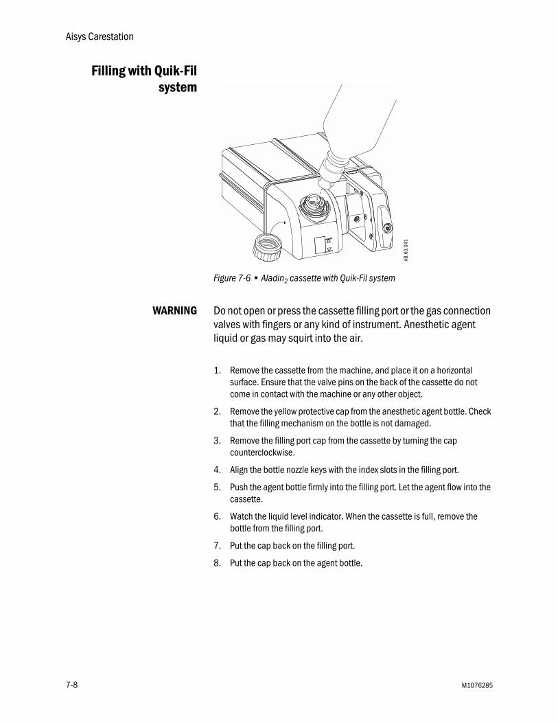
Aisys Carestation
Filling with Quik-Filsystem
Figure 7-6 • Aladin2 cassette with Quik-Fil system
WARNING Do not open or press the cassette filling port or the gas connection valves with fingers or any kind of instrument. Anesthetic agent liquid or gas may squirt into the air.
1. Remove the cassette from the machine, and place it on a horizontal surface. Ensure that the valve pins on the back of the cassette do not come in contact with the machine or any other object.
2. Remove the yellow protective cap from the anesthetic agent bottle. Check that the filling mechanism on the bottle is not damaged.
3. Remove the filling port cap from the cassette by turning the cap counterclockwise.
4. Align the bottle nozzle keys with the index slots in the filling port.
5. Push the agent bottle firmly into the filling port. Let the agent flow into the cassette.
6. Watch the liquid level indicator. When the cassette is full, remove the bottle from the filling port.
7. Put the cap back on the filling port.
8. Put the cap back on the agent bottle.
AB.6
0.04
1
7-8 M1076285

7 Vaporizer
Filling with Saf-T-Filbottle
Figure 7-7 • Aladin2 cassette with Saf-T-Fil mechanism
CAUTION Do not attempt to fill the cassette with desflurane that is warmer than 26˚C/78˚F. The overfill prevention system may lock and prevent cassette filling.
WARNING Do not store filled or partially filled desflurane cassettes above the normal working temperature of 35˚C/95˚F. Storage at high temperature may cause the overpressure valve to vent desflurane vapor into the ambient air.
w Do not open or press the cassette filling port or the gas connection valves with fingers or any kind of instrument. Anesthetic agent liquid or gas may squirt into the air.
1. Remove the cassette from the machine, and place it on a horizontal surface. Ensure that the valve pins on the back of the cassette do not come in contact with the machine or any other object.
2. Remove the cap from the desflurane bottle. Check that the o-ring is correctly fitted on the bottle nozzle.
AB.6
0.05
0
AB.6
0.04
9
M1076285 7-9

Aisys Carestation
3. Insert the nozzle into the filling port, and push the bottle firmly against the spring pressure until it stops.
4. Turn the bottle upwards while keeping it firmly inserted.
5. Watch the liquid level indicator. Do not leave the bottle unattended while it is attached to the cassette.
6. When the liquid level reaches the full mark, lower the bottle to stop the flow of liquid.
7. Remove the bottle from the filling port.
8. Put the cap back on the agent bottle.
7-10 M1076285
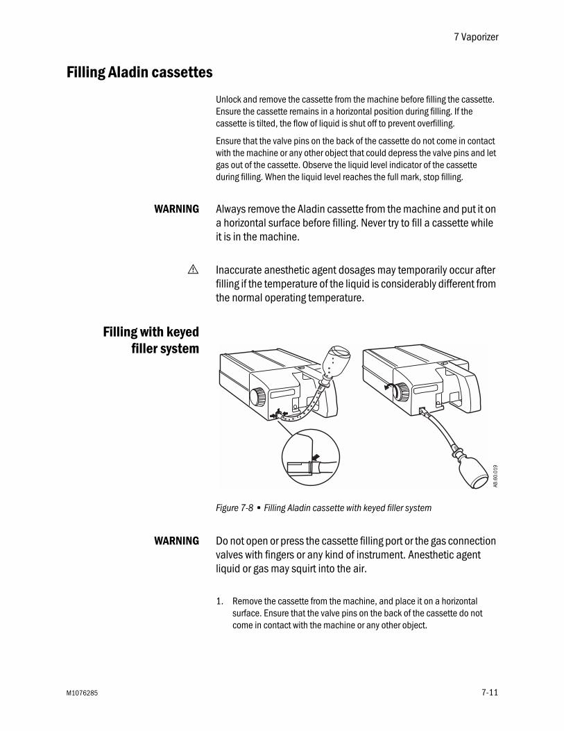
7 Vaporizer
Filling Aladin cassettes
Unlock and remove the cassette from the machine before filling the cassette. Ensure the cassette remains in a horizontal position during filling. If the cassette is tilted, the flow of liquid is shut off to prevent overfilling.
Ensure that the valve pins on the back of the cassette do not come in contact with the machine or any other object that could depress the valve pins and let gas out of the cassette. Observe the liquid level indicator of the cassette during filling. When the liquid level reaches the full mark, stop filling.
WARNING Always remove the Aladin cassette from the machine and put it on a horizontal surface before filling. Never try to fill a cassette while it is in the machine.
w Inaccurate anesthetic agent dosages may temporarily occur after filling if the temperature of the liquid is considerably different from the normal operating temperature.
Filling with keyedfiller system
Figure 7-8 • Filling Aladin cassette with keyed filler system
WARNING Do not open or press the cassette filling port or the gas connection valves with fingers or any kind of instrument. Anesthetic agent liquid or gas may squirt into the air.
1. Remove the cassette from the machine, and place it on a horizontal surface. Ensure that the valve pins on the back of the cassette do not come in contact with the machine or any other object.
AB.6
0.01
9
M1076285 7-11

Aisys Carestation
2. Align the notches on the bottle adapter to the agent bottle collar, and tighten the adapter onto the bottle.
WARNING To avoid exposure to anesthetic agent during filling, ensure that the bottle adapter is properly connected to the bottle.
3. Insert the keyed filler into the agent filling port on the cassette. Make sure that the square end of the filler is flush with the cassette body as shown.
CAUTION Ensure that the keyed filler is properly inserted into the filling port on the cassette. If air leaks into the system, the overfill protection mechanism of the cassette will not function properly. Overfilling the cassette may result in vaporizer delivery failure.
4. Lock the keyed filler by turning the lock and fill wheel fully clockwise.
5. Turn the bottle upside down. Check that the liquid flows evenly into the cassette. If it does not, tighten the wheel until the liquid starts to flow.
6. Watch the liquid level indicator. When the cassette is full, lower the bottle to stop the flow of liquid.
7. Turn the lock and fill wheel a half turn counterclockwise to close the filling port. Wait for the residual anesthetic agent to trickle back into the bottle.
8. Turn the lock and fill wheel fully counterclockwise, and remove the keyed filler from the filling port.
9. Remove the bottle adapter from the anesthetic agent bottle. Put the cap back on the agent bottle.
7-12 M1076285

7 Vaporizer
Filling with Quik-Filsystem
Figure 7-9 • Filling Aladin cassette with Quik-Fil system
WARNING Do not open or press the cassette filling port or the gas connection valves with fingers or any kind of instrument. Anesthetic agent liquid or gas may squirt into the air.
1. Remove the cassette from the machine, and place it on a horizontal surface. Ensure that the valve pins on the back of the cassette do not come in contact with the machine or any other object.
2. Remove the yellow protection cap from the anesthetic agent bottle. Check that the filling mechanism of the bottle is not damaged.
3. Remove the filling port cap from the cassette by turing the cap counterclockwise.
4. Insert the nozzle of the bottle into the filling port.
5. Push the agent bottle firmly into the filling port. Let the agent flow into the cassette.
6. Watch the liquid level indicator. When the cassette is full, remove the bottle from the filling port.
7. Put the cap back on the filling port.
8. Put the cap back on the agent bottle.
AB.6
0.01
8
M1076285 7-13

Aisys Carestation
Filling with Saf-T-Filbottle
Figure 7-10 • Filling Aladin cassette with Saf-T-Fil bottle
CAUTION Do not attempt to fill the cassette with desflurane that is warmer than 26˚C/78˚F. The overfill prevention system may lock and prevent cassette filling.
WARNING Do not store filled or partially filled desflurane cassettes above the normal working temperature of 35˚C/95˚F. Storage at high temperature may cause the overpressure valve to vent desflurane vapor into the ambient air.
w Do not open or press the cassette filling port or the gas connection valves with fingers or any kind of instrument. Anesthetic agent liquid or gas may squirt into the air.
1. Remove the cassette from the machine, and place it on a horizontal surface. Ensure that the valve pins on the back of the cassette do not come in contact with the machine or any other object.
2. Remove the cap from the desflurane bottle. Check that the o-ring is correctly fitted on the bottle nozzle.
3. Insert the nozzle into the filling port, and push the bottle firmly against the spring pressure until it stops.
4. Turn the bottle upwards while keeping it firmly inserted.
5. Watch the liquid level indicator. Do not leave the bottle unattended while it is attached to the cassette.
AB.6
0.01
7
7-14 M1076285

7 Vaporizer
6. When the liquid level reaches the full mark, lower the bottle to stop the flow of liquid.
7. Remove the bottle from the filling port.
8. Put the cap back on the agent bottle.
M1076285 7-15

Aisys Carestation
7-16 M1076285

8 Alarms and Troubleshooting
CAUTION No repair should ever be attempted by anyone not having experience in the repair of devices of this nature. Refer to “Repair policy” in the “User Maintenance” section in Part 2 of the User’s Reference manual.
WARNING If an alarm occurs, safeguard the patient first before performing troubleshooting or doing repair procedures.
In this section Alarms . . . . . . . . . . . . . . . . . . . . . . . . . . . . . . . . . . . . . . . . . . . . . . . . . . . . . . . 8-2
List of alarms . . . . . . . . . . . . . . . . . . . . . . . . . . . . . . . . . . . . . . . . . . . . . . . . . . 8-3
Alarm ranges and default values . . . . . . . . . . . . . . . . . . . . . . . . . . . . . . . . . 8-10
Alarm tests . . . . . . . . . . . . . . . . . . . . . . . . . . . . . . . . . . . . . . . . . . . . . . . . . . . 8-11
Breathing system problems . . . . . . . . . . . . . . . . . . . . . . . . . . . . . . . . . . . . . 8-12
Electrical problems . . . . . . . . . . . . . . . . . . . . . . . . . . . . . . . . . . . . . . . . . . . . 8-13
Pneumatic problems . . . . . . . . . . . . . . . . . . . . . . . . . . . . . . . . . . . . . . . . . . . 8-13
M1076285 8-1

Aisys Carestation
Alarms
Alarms are divided into technical alarms and parameter alarms. These alarms may be high priority, medium priority, or informational. When an alarm occurs during a case, an alarm tone sounds and the alarm message is displayed in the alarm message field.
Technical alarms result from a technical problem and occur whether or not a patient is connected to the system. Parameter alarms are calculated limits and limits that are set by the user on the Alarm Setup menu. Parameter alarms occur only during a case.
Silencing an alarm stops the audible tone for 120 seconds. Pushing the Silence Alarms key when no medium or high priority alarms are active suspends audible alarm tones for 90 seconds.
Alarm priorities Alarm priority is indicated by the color of the alarm message and the alarm LED located next to the alarm silence button.
High-priority alarm messages appear in white text on a red background. During a high-priority alarm, the red LED flashes.
Medium-priority alarm messages appear in yellow text on a gray background. During a medium-priority alarm, the yellow LED flashes.
Informational alarms appear in white text on a gray background. During an informational alarm, the yellow LED is on solid.
When a high-priority alarm is active at the same time as a medium-priority alarm or an informational alarm, the red and yellow LEDs flash. When a high-priority alarm is active at the same time as an informational alarm, the red LED flashes and the yellow LED is on solid. When a medium-priority alarm is active at the same time as an informational alarm, the yellow LED flashes. Pushing the Silence Alarms key shuts off the LED until the end of the alarm silence.
Display changesduring alarms
Messages may appear in the waveform field during some alarms. If more than one alarm has a message, the message for the highest priority alarm is displayed. The message is removed when the alarm is resolved.
Messages for high-priority alarms use red text. Messages for medium-priority alarms use yellow text. Informational messages use white text.
Some device related alarm, such as ‘Reverse flow’ and ‘No insp flow sensor,’ will de-escalate priority when the alarm is acknowledged by pushing the Silence Alarms key.
When the O2 pipeline supply pressure drops to less than 252 kPa, the lower-right corner of the display toggles between the O2 supply information and the respiratory data.
8-2 M1076285

8 Alarms and Troubleshooting
Some patient parameter alarms, such as ‘Ppeak high and FiO2 Low, will latch when the alarm condition is corrected. When an alarm is latched, it is displayed in white text on a black background. The parameter box will stop flashing. The alarm will remain in this condition until it is acknowledged by pushing the Silence Alarms key or until the alarm re-occurs. When the alarm is acknowledged, it is removed from the screen. If an alarm has latched and the alarm re-occurs before it is acknowledged, the alarm will revert to an active state.
Battery indicator The color and fill amount of the battery in use symbol indicates the amount of battery power remaining. Green indicates greater than 10 minutes of battery power remaining. Yellow indicates less than 5 minutes battery power remaining.
Internal failure ‘Internal problem prevents normal operation’ will show on the display during a software or hardware failure that requires service. If this message occurs, contact a Datex-Ohmeda trained service representative.
List of alarms
If the corrective action does not resolve the alarm message, contact a Datex-Ohmeda trained service representative
Circuit pressures and volumetric flows are measured by the ventilator and airway gas module. If the Data Source is set to Patient, the displayed waveforms and numeric information are measured by the airway gas module. Although not displayed, the ventilator measurements continue and if a measured value violates an alarm setting, the appropriate alarm occurs. The value highlighted in the parameter numeric box may not appear to have violated the alarm setting. Changing the Data Source to Vent will display the circuit pressures and volumetric flows measured by the ventilator.
Message Priority Cause Action
AA, CO2 monitoring not connected
Medium External Gas Monitor setting is set to No on the Install/Service menu.
Set External gas monitor setting to Yes if the system uses a stand-alone monitor for O2, AA, and CO2.
Adjust low MV limit Medium Low MV limit is off in SIMV/PSV, SIMV-PC, or PSVPro modes.
Increase Low MV alarm limit to improve patient disconnection detection.
Agent output not accurate. Schedule service.
Medium Vaporizer detected a flow meter temperature sensor failure and is using a default temperature value.
Contact a Datex-Ohmeda trained service representative.
Air pressure low. Increase O2%.
High Air pipeline pressure is less than 252 kPa (36 psi) and the air cylinder pressure dropped below 2633 kPa (381 psi) for one second.
Ensure the air pipeline and cylinder are properly connected.
M1076285 8-3

Aisys Carestation
Air supply pressure low Medium Air pipeline pressure is less than 252 kPa (36 psi) and the air cylinder pressure dropped below 2633 kPa (381 psi) for one second.
Ensure the air pipeline and cylinder are properly connected.
Apnea Medium Apnea time delay (10-30 seconds) has passed without a measured breath.
Check for leaks in the patient circuit.Check for patient disconnection.
Apnea >120 s High Apnea time exceeds 120 seconds.
Check for leaks or blockages in the breathing circuit.Ensure the Bag/Vent switch is in the Vent position. Check the patient.
Backup Mode active Informational No spontaneous breaths in set period of time (Backup Time) and 30 seconds have passed since starting PSVPro mode.
Select a new ventilation mode.
Breathing System loose Informational The breathing system is not latched.
Push the breathing system onto the frame and ensure it latches.
Calibrate flow sensors Informational Flow calibration failure. Calibrate the flow sensors.Calibrate O2 sensor Informational Calibration failure or O2 > 110%. Calibrate the O2 cell.
Replace the O2 cell if necessary.Calibrate, dry, or replace flow sensors
Informational Patient volume mismatch occurred.
Calibrate, dry or replace the flow sensors. Start a new case.
Cannot deliver agent setting at set flow
Informational Output flow ≥ 6.0 l/min for > 10 seconds.
Reduce the flow.
Cannot identify cassette Medium The identification coding of the cassette cannot be interpreted.
Exchange the cassette. Contact a Datex-Ohmeda trained service representative to have the faulty cassette serviced.
Cannot monitor Air pipeline Medium Air Pipeline pressure is invalid. Check pipeline supply pressure.Cannot monitor gas supplies Informational Hardware failure. Contact a Datex-Ohmeda trained service
representative.Cannot monitor O2 pipeline Medium O2 Pipeline pressure is invalid. Check pipeline supply pressure.Cannot read gas supply pressures
Medium Transducer failure. Contact a Datex-Ohmeda trained service representative.
Cassette overfilled, replace cassette
Medium Agent level sensor indicates the cassette is overfilled.
Exchange the cassette with one filled to a proper level. Contact a Datex-Ohmeda trained service representative to drain the cassette.
Check agent level Informational Cassette reporting a value of 1/4 or empty.
Fill the cassette.
Check cassette. Set agent. Medium Cassette pressure is out of range. Agent flow interrupted or control failure.System or cassette temperature is out of range. Agent setting is Off.
Try another cassette.Remove and reinsert the cassette.Ensure the room temperature is within specified range. Set the agent to the desired concentration.
Check circuit connections Medium Breaths detected in circle circuit while non-circle circuit is selected.
Check circle circuit connections and settings.
Message Priority Cause Action
8-4 M1076285

8 Alarms and Troubleshooting
Check D-Fend Medium Water trap not attached. Check that the water trap is properly attached to the airway module.
Check flow sensors Medium System has detected an improper flow pattern in the breathing circuit.
Ensure the internal flow sensors are connected correctly.
Check sample gas out Medium Possible blockage in airway module sample gas outlet.
Check for blockage in the airway module sample gas outlet. Remove blockage.
Circuit leak Medium Vent TVexp < half of vent TVinsp for at least 30 seconds.
Check for leaks in the patient circuit.Calibrate flow sensors. If problem persists, replace flow sensors.
Circuit leak silenced Informational Setting on Alarm Setup menu.Vent TVexp < 50% of vent TVinsp for at least 30 seconds.
Message indicates that the Leak Audio alarm is turned off.
Circuitry >75C shutdown possible
Medium Power supply temperature exceeds 75C.
Shut down system as soon as possible. Then, check cooling fans and filters.
Cooling fan needs service. System OK.
Medium Fan reporting error. Shut down system as soon as possible. Then, check cooling fans and filters.
Cooling fans failed. May overheat.
Medium Fan reporting error. Shut down system as soon as possible.Contact a Datex-Ohmeda trained service representative.
Display panel controls failure Medium Communication lost between panel and key pad.
Turn the system off and back on.
EtCO2 high High EtCO2 > high alarm limit. Check the patient and EtCO2 settings.Check if absorbent needs to be changed.
EtCO2 low High EtCO2 < alarm limit. Ensure the patient is properly intubated.Check for leaks or blockages in the patient circuit.
EtDES high Medium EtDES > alarm limit. Set the alarm limits appropriately. Decrease the agent concentration.
EtDES low Informational EtDES < alarm limit. Check the fill level on the vaporizers.Set alarm limit appropriately.Increase the agent concentration.
EtENF high Medium EtENF > alarm limit. Set the alarm limits appropriately. Decrease the agent concentration.
EtENF low Informational EtENF < alarm limit. Check the fill level on the vaporizers.Set alarm limit appropriately. Increase the agent concentration.
EtHAL high Medium EtHAL > alarm limit. Set the alarm limits appropriately. Decrease the agent concentration.
EtHAL low Informational EtHAL < alarm limit. Check the fill level on the vaporizers. Set alarm limit appropriately.Increase the agent concentration.
EtISO high Medium EtISO > alarm limit. Set the alarm limits appropriately. Decrease the agent concentration.
EtISO low Informational EtISO < alarm limit. Check the fill level on the vaporizers.Set alarm limit appropriately.Increase the agent concentration.
EtO2 high Medium EtO2 > high alarm limit. Set the alarm limits appropriately. Decrease the O2 concentration.
Message Priority Cause Action
M1076285 8-5

Aisys Carestation
EtO2 low Medium EtO2 < low alarm limit. Set the alarm limits appropriately. Increase the O2 concentration.
EtSEV high Medium EtSEV > alarm limit. Set the alarm limits appropriately. Decrease the agent concentration.
EtSEV low Informational EtSEV < alarm limit. Check the fill level on the vaporizers.Set alarm limit appropriately.Increase the agent concentration.
FiCO2 high. Absorbent OK? High FiCO2 > alarm limit. Check if absorbent needs to be changed.Check the patient.
FiDES high Medium FiDES > alarm limit. Set the alarm limits appropriately. Decrease the agent concentration.
FiDES low Informational FiDES < alarm limit. Check the fill level on the vaporizers.Set alarm limit appropriately.Increase the agent concentration.
FiENF high Medium FiENF > alarm limit. Set the alarm limits appropriately. Decrease the agent concentration.
FiENF low Informational FiENF < alarm limit. Check the fill level on the vaporizers.Set alarm limit appropriately.Increase the agent concentration.
FiHAL high Medium FiHAL > alarm limit. Set the alarm limits appropriately. Decrease the agent concentration.
FiHAL low Informational FiHAL < alarm limit. Check the fill level on the vaporizers.Set alarm limit appropriately.Increase the agent concentration.
FiISO high Medium FiISO > alarm limit. Set the alarm limits appropriately. Decrease the agent concentration.
FiISO low Informational FiISO < alarm limit. Check the fill level on the vaporizers.Set alarm limit appropriately.Increase the agent concentration.
FiO2 high Medium FiO2 > high alarm limit. Check the O2 setting.Recalibrate the O2 cell and the airway module.
FiO2 low High FiO2 < low alarm limit. Check O2 setting.Check for leaks or blockages in the patient circuit.
FiSEV high Medium FiSEV > alarm limit. Set the alarm limits appropriately. Decrease the agent concentration.
FiSEV low Informational FiSEV < alarm limit. Check the fill level on the vaporizers.Set alarm limit appropriately.Increase the agent concentration.
For mech vent, set Bag/Vent switch
Informational Bag/Vent switch is set to Bag and the ACGO switch is set to Circle.
Move switch to the Vent position to start mechanical ventilation.
Gas monitoring not available Medium Airway module hardware failure. Replace airway module.Increase low MV limit Medium Low MVexp limit < half of
measured MVexp.Increase Low MV alarm limit to improve patient disconnection detection.
Insert cassette Informational Cassette removal detected during active delivery.
Reinsert the cassette.
Inspiration stopped Medium High airway pressure. Check system for blockages.Internal failure. System may shut down.
High Power controller software failure. Contact a Datex-Ohmeda trained service representative.
Message Priority Cause Action
8-6 M1076285

8 Alarms and Troubleshooting
Internal failure. System may shut down.
Medium Power controller software failure. Contact a Datex-Ohmeda trained service representative.
Memory (EEPROM) failure Informational Software error. Contact a Datex-Ohmeda trained service representative.
Module fail. No CO2, AA, O2 data.
Medium Airway module hardware failure. Replace module.
Module not compatible Informational The monitoring module detected is not compatible with system software.
Remove the incompatible module.
Move Bag/Vent Switch to Bag Medium Bag/Vent switch is in the wrong position to start case.
Move switch to the Bag position.
MVexp high Medium MVexp > MVexp high alarm limit (for nine breaths or 1 minute).
Change TV, RR, I:E, or PEEP to reset the minute volume to below the MVexp high alarm limit.
MVexp low Medium MVexp < MVexp low alarm limit (for nine breaths or 1 minute).
Change TV, RR, I:E, or PEEP to reset the minute volume to above the MVexp low alarm limit.
N2O supply pressure low Informational N2O pipeline pressure is less than 252 kPa (36 psi) and the N2O cylinder pressure is less than 2633 kPa (381 psi).
Ensure the N2O pipeline and cylinder are properly connected.
Negative airway pressure High Paw < -10 cmH2O Check for blockages in the patient circuit.No battery backup Medium Battery or charging failure. Between cases turn the system circuit
breaker off, then back on after 15 seconds to reset the system.
No battery backup for monitor Informational Monitor power cable is unplugged.
Make sure the monitor power cable is plugged in.
No exp flow sensor Medium Electrical signals show the flow sensor is not connected.
Connect the flow sensor.Replace the flow sensor if necessary.
No fresh gas flow! High Possible patient detected while system is in standby.
Disconnect the patient or start a case.
No fresh gas flow? High Possible fresh gas flow occlusion or loss of gas pressure.
Switch to circle circuit or bag the patient.Check pipeline supply connection.
No insp flow sensor Medium Electrical signals show the flow sensor is not connected.
Connect the flow sensor.Replace the flow sensor if necessary.
O2 flush stuck on? Informational Switch is detected “on” continuously > 30 seconds.
Check flush valve. Ensure flush valve is not sticking.
O2 monitoring not connected Medium O2 cell not connected. Install airway gas module or connect the O2 cell.
O2 supply pressure low High O2 pipeline pressure is less than 252 kPa (36 psi) and the O2 cylinder pressure dropped below 2633 kPa (381 psi) for one second.
Ensure the O2 pipeline and cylinder are properly connected.
PEEP high. Blockage? High Paw ≥ sustained limit for 15 seconds.1
Check for blockages in the patient circuit.
Plug in power cable. On battery.
Medium The mains supply is not connected or has failed and the system is using battery power.
Ventilate manually to save power.Make sure the power cable is plugged in and system circuit breaker is on.
Ppeak high High Paw > Pmax alarm limit Check for blockages in the patient circuit.
Message Priority Cause Action
M1076285 8-7

Aisys Carestation
Ppeak low. Leak? Medium Peak airway pressure < low P min + 4 cmH2O for 20 consecutive seconds if the set respiratory rate is four or higher and 30 seconds if the set respiratory rate is less than four breaths/min.
Check for leaks in the patient circuit.
Replace D-Fend Medium Buildup in airway module sample line.
Replace D-Fend.
Replace exp flow sensor Informational EEPROM calibration data read failure.
Replace the expiratory flow sensor.
Replace insp flow sensor Informational EEPROM calibration data read failure.
Replace the inspiratory flow sensor.
Replace O2 sensor Informational O2 < 5%. Calibrate the O2 cell.Replace the O2 cell if necessary.
Reverse exp flow. Check valves OK?
Medium Flow toward the patient seen in the expiratory flow sensor during inspiration for six breaths in a row.
Check the flow sensor condition. Replace the expiratory check valve between cases.Zero flow transducers between cases.
Reverse insp flow. Check valves OK?
Medium Flow through inspiratory sensor during expiration for six breaths in a row.
Check the flow sensor condition. Replace the expiratory check valve between cases.Zero flow transducers between cases.
RR high Medium RR > high alarm limit. Set the alarm limits appropriately or adjust the RR setting.
RR low Medium RR < low alarm limit. Set the alarm limits appropriately or adjust the RR setting.
Sample line blocked Medium Airway module sample line is blocked.
Replace airway module sample line.
Service calibration advised Informational Calibration data corrupt. Contact a Datex-Ohmeda trained service representative.
Set Alt O2 flow.Check agent setting.
Medium Multiple possible causes for the failure.
Contact a Datex-Ohmeda trained service representative.
System leak? Informational Leak detected between ventilator and patient circuit.
Check for leaks in the breathing system.
System shutdown in <5 min High Remaining battery power is between one and five minutes.
Plug in the power cable. Check that the system circuit breaker is on.
Try another cassette. Schedule service.
Medium Vaporizer detected a cassette temperature failure. Delivery cannot continue.
Insert a different cassette.Contact a Datex-Ohmeda trained service representative.
Turn power Off and On for self tests
Informational System has been operating for longer than 12 hours without a power up self test.
Turn power off and back on between cases to perform a self test.
Turn switch on to continue use High System is in therapy when System switch is turned to Standby.
Turn the System switch to On to continue therapy. The system will return to normal function. If System switch is not turned to On within 8 seconds, the system will shut down.
TV not achieved Informational Measured tidal volume is < set tidal volume.
Check for leaks in the patient circuit.Check for leaks in the breathing system.
TVexp high Medium TVexp > TVexp high alarm limit (for nine breaths).
Change TV, RR, I:E, or PEEP or change the tidal volume to reset TVexp high alarm limit.
Message Priority Cause Action
8-8 M1076285

8 Alarms and Troubleshooting
TVexp low Medium TVexp < TVexp low alarm limit (for nine breaths).
Change TV, RR, I:E, or PEEP or change the tidal volume to reset TVexp low alarm limit.
Unable to drive bellows Informational Bellows is collapsed. Check the drive gas. Increase fresh gas flow (or push the O2 flush button) to fill the bellows.
Using battery. Power Controller fail.
Medium Mains supply is OK, but the system is running on the battery.
Shut down the system as soon as possible, and contact a Datex-Ohmeda trained service representative.
Vaporizer failure Medium Internal issue with agent delivery hardware.
Change anesthesia method or use an alternate machine. Shutdown the system as soon as possible and contact a Datex-Ohmeda trained service representative.
Ventilate Manually High Software or hardware failure prevents mechanical ventilation.
Use a manual bag to ventilate the patient or use an alternate machine. Shutdown the system as soon as possible and contact a Datex-Ohmeda trained service representative.
Ventilate Manually Medium Ventilator monitoring only. Software or hardware failure.
Contact a Datex-Ohmeda trained service representative.
Ventilator has no drive gas High Drive gas supply is not sufficient to mechanically ventilate.
Check drive gas supply. Ventilate manually until drive gas supply is restored.
Vol and Apnea monitoring off Informational Non Circle ACGO selected.Non Circle SCGO selected.
Message will clear when circle circuit is selected.
Vol vent only. No PEEP or PSV. Medium Manifold pressure error. Pressure control unavailable. Medium priority alarm when Bag/Vent switch is in Vent and running PCV, PSVPro, or SIMV-PC mode.
Use volume control ventilation mode. Shut down system as soon as possible.Contact a Datex-Ohmeda trained service representative.
Vol vent only. No PEEP or PSV. Informational Manifold pressure error.Pressure control unavailable. Informational priority alarm when Bag/Vent switch is in Vent and not running PCV, PSVPro, or SIMV-PC mode; Bag/Vent switch is in Bag; or Non-circle circuit or ACGO is selected.
Continue to use volume control ventilation mode or ventilate manually. Shut down system as soon as possible.Contact a Datex-Ohmeda trained service representative.
Volume sensors disagree Informational TVexp > larger of ([TVinsp + 3* ‘set TV’] or [TVinsp + 100]) for six breaths.
Calibrate the flow sensors.Replace the flow sensors if the message does not clear.
Message Priority Cause Action
1The sustained pressure threshold is calculated from the pressure limit setting. The sustained limit is calculated as follows:Mechanical Ventilation On - Volume Mode
For Plimit ≤ 30 cmH2O; the sustained pressure limit is 6 cmH2O plus Set PEEP.For Plimit between 30 and 60 cmH2O; the sustained pressure limit is 20% of the Plimit plus Set PEEP.For Plimit ≥ 60 cmH2O; the sustained pressure limit is 12 cmH2O plus Set PEEP.
Mechanical Ventilation On – Pressure Mode
Sustained pressure limit is 50% of set Pinsp or 4 cmH2O, whichever is greater, plus Set PEEPandPmax – Pmin must be less than 50% of set Pinsp or 4 cmH2O, whichever is greater.
Mechanical Ventilation Off For Plimit ≤ 60 cmH2O; the sustained pressure limit is 50% of the Plimit setting.For Plimit > 60 cmH2O; the sustained pressure limit is 30 cmH2O.
M1076285 8-9

Aisys Carestation
Alarm ranges and default values
Alarm Range Increment Default
EtCO2 High 0.1 – 15, Off %0.1 – 15, Off kPa0-115, Off mmHg
0.1%0.1 kPa1 mmHg
6.5%6.5 kPa50 mmHg
EtCO2 Low Off, 0.0 – 14.9%Off, 0.0 – 14.9 kPaOff, 0-114 mmHg
0.1%0.1 kPa1 mmHg
OffOffOff
EtDES High 0.1 – 20, Off % 0.1% OffEtDES Low Off, 0.1 – 19.9% 0.1% OffEtENF High 0.1 – 7.0, Off % 0.1% OffEtENF Low Off, 0.1 – 6.9% 0.1% OffEtHAL High 0.1 – 7.0, Off % 0.1% 5%EtHAL Low Off, 0.1 – 6.9% 0.1% OffEtISO High 0.1 – 7.0, Off % 0.1% OffEtISO Low Off, 0.1 – 6.9% 0.1% OffEtO2 High 18-100, Off % 1% OffEtO2 Low Off, 0 – 99% 1% OffEtSEV High 0.1 – 10.0, Off % 0.1% OffEtSEV Low Off, 0.1 – 9.9% 0.1% OffFiCO2 High 0.1 – 15, Off %
0.1 – 15, Off kPa0-115, Off mmHg
0.1%0.1 kPa1 mmHg
OffOffOff
FiDES High 0.1 – 20.0, Off % 0.1% 15%FiDES Low Off, 0.1 – 19.9% 0.1% OffFiENF High 0.1-7.0, Off % 0.1% 5%FiENF Low Off, 0.1 – 6.9% 0.1% OffFiHAL High 0.1 – 7.0, Off % 0.1% 5%FiHAL Low Off, 0.1 – 6.9% 0.1% OffFiISO High 0.1 – 7.0, Off % 0.1% 5%FiISO Low Off, 0.1 – 6.9% 0.1% OffFiSEV High 0.1 – 10.0, Off % 0.1% 8%FiSEV Low Off, 0.1 – 9.9% 0.1% OffHigh FiO2 19 – 100, Off % 1% OffHigh MV 0.5 – 30.0, Off l/min 0.5 l/min 10 l/minHigh RR 2 – 100, Off bpm 1 bpm OffHigh TV 20 – 1600, Off ml 20 ml 1000 mlLow FiO2 18 – 99% 1% 21%Low MV Off, 0.1 – 10.0 l/min 0.1 l/min 2 l/minLow RR Off, 0 – 99 bpm 1 bpm OffLow TV Off, 5 – 20 ml
20 – 1500 ml5 ml20 ml
Off
Pmax (only high) 12 -100 cmH2O, hPa1.2– 9.8 kPa 12 – 98 mbar9 -74 mmHg
1 cmH2O, hPa0.1 kPa1 mbar1 mmHg
40 cmH2O, hPa4 kPa4 mbar30 mmHg
8-10 M1076285

8 Alarms and Troubleshooting
Alarm tests1. Connect a test lung to the patient connection.
2. Start a case.
3. Set the Bag/Vent switch to Vent.
4. Set the O2 concentration to 30%, and allow the O2 reading to stabilize.
5. Test the O2 alarms:
• Set the FiO2 low alarm limit to 50%. Make sure an FiO2 low alarm occurs.
• Set the FiO2 low alarm limit back to 21% and make sure that the FiO2 low alarm cancels.
• Set the FiO2 high alarm limit to 50%.
• Push the O2 flush button.
• Make sure the FiO2 high alarm occurs.
• Set the FiO2 high alarm limit back to 100%. Make sure that theFiO2 high alarm cancels.
6. Test the MVexp low alarm:
• Go to the Alarm Setup menu.
• Set the MV low alarm limit to greater than the measured minute volume.
• Make sure that a MVexp low alarm occurs.
• Set the MV low alarm limit to off.
7. Test the Ppeak high alarm:
• Set the Pmax to less than the peak airway pressure.
• Make sure that the Ppeak high alarm occurs.
• Set the Pmax to the desired level.
8. Test the PEEP high. Blockage? alarm:
• Close the APL valve.
• Set the Bag/Vent switch to Bag. Mechanical ventilation stops.
• Block the patient connection and push the O2 flush button.
• Make sure that the PEEP high. Blockage? alarm occurs after approximately 15 seconds.
9. Test the Ppeak low. Leak? alarm:
• Unblock the patient connection.
• Set the Bag/Vent switch to Vent.
• Set the tidal volume and total flow to minimum.
• Other alarms such as MVexp low can occur.
• Make sure that the Ppeak low. Leak? alarm occurs.
10. Set all alarm limits to approved clinical values.
M1076285 8-11

Aisys Carestation
Breathing system problems
Symptom Problem Solution
Gas scavenging flow is too low or too high.
Scavenging extract flow problem. Use a different scavenging extraction system. Verify flow is within specification.
Filter blockage. Active systems have a flow indicator.
Replace the filter. Refer to Remove the AGSS receiver filter in the “Cleaning and Sterilization” section in Part 2 of the User’s Reference manual.
The bellows fills when the Bag/Vent switch is set to Bag or the bag fills when the switch is set to Vent.
Leak through Bag/Vent switch. Contact a Datex-Ohmeda trained service representative to repair the system.
The ventilator does not read the position of the Bag/Vent switch.
Ventilator or absorber malfunction. Ventilate manually. Contact a Datex-Ohmeda trained service representative to repair the system.
APL valve does not operate correctly. APL valve problem. Replace APL Valve seal and diaphragm.
Large breathing system leak not quickly located (in Bag mode).
Bag hose not connected properly. Ensure that the Bag Hose is connected to the Bag port (below the APL Valve).
Absorber canister not installed correctly.
Reinstall the absorber canister, ensure both pins are engaged.
Bellows falls below top of indicator during “Bellows assembly test.”
Leak in the breathing system. Check, clean, or reposition the pressure relief valve. If the problem persists, replace the pressure relief valve, bellows base, or bellows assembly.
8-12 M1076285

8 Alarms and Troubleshooting
Electrical problems
WARNING If a circuit breaker opens frequently, do not use the system. Have a Datex-Ohmeda trained service representative repair the system.
Pneumatic problems
Symptom Problem Solution
Mains indicator is not on. The electrical power cable is not connected.
Connect the power cable.
The inlet circuit breaker (switch) is off. Turn the circuit breaker on.The power cable is damaged. Replace the power cable.The electrical socket the power cable connects to has no power.
Use a different electrical socket.
An internal fuse is open. Have a Datex-Ohmeda trained service representative repair the system.
One electrical outlet does not have power.
The outlet circuit breaker is off. Turn the circuit breaker on.
A circuit breaker opens frequently. Equipment connected to the outlet(s) uses more current than the circuit breaker rating.
Use a different power supply for some of the equipment.
The equipment connected to the outlet has a short.
Have a Datex-Ohmeda trained service representative repair the system.
The real time clock on the anesthesia display does not maintain accurate time and date.
The battery in the anesthesia display needs to be replaced.
Have a Datex-Ohmeda trained service representative replace the battery.
Symptom Problem Solution
High-pressure leak test fails. Controls are not set correctly. Ensure no gas is flowing, turn off the auxiliary flowmeter, and repeat the test.
Incorrect cylinder connection. Make sure that there is only one cylinder gasket, the gasket is in good condition, and the connection is tight.
Low-pressure leak with a vaporizer OFF.
Anesthesia machine problem. Contact a Datex-Ohmeda trained service representative.
M1076285 8-13

Aisys Carestation
8-14 M1076285

Warranty
This Product is sold by Datex-Ohmeda under the warranties set forth in the following paragraphs. Such warranties are extended only with respect to the purchase of this Product directly from Datex-Ohmeda or Datex-Ohmeda’s Authorized Dealers as new merchandise and are extended to the Buyer thereof, other than for the purpose of resale.
For a period of twelve (12) months from the date of original delivery to Buyer or to Buyer’s order, but in no event for a period of more than two years from the date of original delivery by Datex-Ohmeda to a Datex-Ohmeda Authorized Dealer, this Product, other than its expendable parts, is warranted against functional defects in materials and workmanship and to conform to the description of the Product contained in this User’s Reference manual and accompanying labels and/or inserts, provided that the same is properly operated under the conditions of normal use, that regular periodic maintenance and service is performed and that replacements and repairs are made in accordance with the instructions provided. This same warranty is made for a period of thirty (30) days with respect to expendable parts. The foregoing warranties shall not apply if the Product has been repaired other than by Datex-Ohmeda or in accordance with written instructions provided by Datex-Ohmeda, or altered by anyone other than Datex-Ohmeda, or if the Product has been subject to abuse, misuse, negligence, or accident.
Datex-Ohmeda’s sole and exclusive obligation and Buyer’s sole and exclusive remedy under the above warranties is limited to repairing or replacing, free of charge, at Datex-Ohmeda’s option, a Product, which is telephonically reported to the nearest Datex-Ohmeda Customer Service Center and which, if so advised by Datex-Ohmeda, is thereafter returned with a statement of the observed deficiency, not later than seven (7) days after the expiration date of the applicable warranty, to the Datex-Ohmeda Customer Service and Distribution Center during normal business hours, transportation charges prepaid, and which, upon Datex-Ohmeda’s examination, is found not to conform with above warranties. Datex-Ohmeda shall not be otherwise liable for any damages including but not limited to incidental damages, consequential damages, or special damages.
There are no express or implied warranties which extend beyond the warranties hereinabove set forth. Datex-Ohmeda makes no warranty of merchantability or fitness for a particular purpose with respect to the product or parts thereof.


Index
A
Absorber canister release 2-7ACGO 2-8, 2-9
positive low-pressure leak test 5-8scavenging the ACGO sample flow 2-10
Advanced breathing system 2-6Agent
set measured 3-7settings 2-12
AGSS 2-4active 3-18connecting active with a flow indicator 3-19connecting active without a flow indicator 3-19passive 3-17
Airadjust 3-7select 3-3
Airway modules 6-2agent identification 6-6connection to a patient 6-4
Aladin cassettesAladin 7-3Aladin2 7-2cleaning and disinfection 7-5filling Aladin cassettes 7-11filling Aladin2 cassettes 7-6installing cassettes 7-5
Alarm 8-2priorities 8-2ranges and defaults 8-10silence countdown 2-12silence key 2-11tests 8-11
Alternate O2 control 2-2, 2-3, 3-14Auxiliary O2 2-2, 2-3
B
Bag/Vent switch 2-6, 2-7Battery 1-5
indicator 8-3indicator field 2-12
Breathing system 2-2, 8-12
C
Calibrationairway module 6-7flow sensor 5-9
Cassette 2-2controls 2-5insert 5-9test delivery 5-7
Checkout 4-1Circuit
circle 3-7non-circle 2-9, 3-7
Condenserdrain button 2-8operation 3-16
Controlsalternate O2 3-14display 2-11
D
Displayanesthesia system 2-12controls 2-11
E
End case 3-4EZchange Canister 2-8
operation 3-15
F
Filling Aladin cassettesfilling with keyed filler system 7-11filling with Quik-Fil system 7-13filling with Saf-T-Fil bottle 7-14
Filling Aladin2 cassettesfilling with Easy-Fil system 7-6filling with Quik-Fil system 7-8filling with Safe-T-Fil bottle 7-9
G
Gas setup 3-7
M1076285 I-1

Aisys Carestation
L
Low Pressure Leak test 5-6
M
Manual ventilation 2-7Menu
remove 2-17select item 2-15using 2-14
N
Negative low pressure leak test 5-6
O
O2 flowadjust 3-7start 3-3
P
Preoperative checkout 4-2Problems
breathing system 8-12electrical 8-13pneumatic 8-13
Q
Quick keys 2-11changing gas settings using 3-7changing ventilator settings using 3-5
S
Scavenginga gas monitor sample flow 2-10ACGO sample flow 2-10from an auxiliary manual breathing circuit 2-10
Setupchanging circuit type 3-7changing gas and settings 3-7gas 3-7vent 3-5
Spirometrymenu functions 3-8reference loop 3-10split screen 3-9viewing loops 3-10
Split screen 3-11Start case 3-3Suction 2-3System
turn on 3-2
T
Timer 2-11start/stop 2-11
Troubleshootingbreathing system 8-12electrical 8-13Pneumatic 8-13
V
Vaporizer 7-1controls 2-5
Vaporizer cassettesfilling Aladin cassettes 7-11filling Aladin2 cassettes 7-6installing cassettes 7-5
Ventilatorchanging modes and settings 3-6modes 3-5settings 2-12setup 3-5
I-2 M1076285

AisysUser’s Reference Manual EnglishM107628505 06 18 05 02Printed in USA©Datex-Ohmeda, Inc.
All rights reserved