soft ferrite core - Mahindra · PDF fileresponsibility and commitment to...
43
PRODUCT GUIDE SOFT FERRITE CORES Mahindra CIE Automotive Limited Magnetic Product Division (MPD)
Transcript of soft ferrite core - Mahindra · PDF fileresponsibility and commitment to...

P R O D U C T G U I D E
SOFT FERRITE CORES
Mahindra CIE Automotive LimitedMagnetic Product Division (MPD)

About Mahindra CIE Automotive
Mahindra CIE Automotive Limited is the listed entity which operates as a single company having 6 business lines. In 2013, the Mahindra Group announced its global alliance with CIE Automotive of Spain with intent of creating an automotive supplier that would rank amongst the Top 100 globally.
Mahindra CIE Automotive, combined the Mahindra Group's automotive component operations held under the Systech Sector with CIE Automotive's European Forgings Operations.
The Systech automotive component business covered a product protfolio spanning stampings, castings, forgings, gears, magnetic Products and composites with operations in India. Germeny, Italy and the UK. CIE's European forging business has operations in Spain and Lithuania.
About Magnetic Product DivisionMahindra CIE (MPD) - The pioneers and leaders
MPD pioneers the ferrite manufacturing process in India four decades ago and has continuously kept pace with the changing needs of the industry. Today as the largest manufacturer of ferrite, we offer the widest range of Hard & Soft ferrite products in the Indian sub-continent.
Leadership Through Quality An TS16949:2009 Company
Ferrite manufacturing is highly technology intensive and involves in diverse fields like chemical, ceramic, metallurgical, mechanical, electrical & electronics engineering. Quality at our company is the outcome of continuous team effort backed by years of experience and expertise in ferrite technology, supported by the best of plant and equipment Our quality management systems have been certified to conform to TS 16949:2009 standard. After all, most of the electronics & automotive giants in India depend on us for international quality ferrites. Mahindra CIE - MPD has been certified under BS OHSAS 18001:2007 and ISO 14001:2004. MPD has in place an Occupational Health, Safety, and Environmental Management System. It demonstrates MPD’s responsibility and commitment to environmental-friendly business practices, with minimal or no impact on the environment.
A wide range of Soft & Hard Ferrites from a single reliable source.
We are fully geared to meet the ever changing and exacting demands of the rapidly growing electronics industry. The component industry traditionally being amongst the most competitive, our efforts are towards working with customers to develop new products and materials as well as improve process capability substantially, adding value to the customers. This product guide is intended to familarise you with our range of products and help you choose the one best suited to your requirements. Of course we also would welcome your suggestion / feedback which would guide our development efforts for the future.
SOFT FERRITE CORE PRODUCT GUIDE | 2

CONTENTS
• Material Grades
• Material Characterestics Graphs
• Cross Reference Table
• EE Cores
• EER , EEC , ETD Cores
• EI Cores
• EFD Cores
• EP Cores
• EPC and FQKT Cores
• PQ Cores
• RM Cores
• ESQ and USQ Cores
• Planar Cores
• UU and UI Cores
• Colur FBT Core
• Ferrite Bars
• Torroids
• Drum Cores
• Small rods
SOFT FERRITE CORE PRODUCT GUIDE | 3

MATERIAL GRADES
Property Symbol Unit Test condition
Initial permeability (±25%) μi ---- 0.1mT, 25oC 2400 2200 2200 2200 2400 3000 3800 3000 4000 4500 5000 6000 7000 10000 800 2000 3400 1200 2000 2300
1200A/m, 25oC 500 500 490 510 510 500 550 480 470 470 450 400 400 430 430 470 510 440 500 420
1200A/m, 100oC 380 400 390 420 410 390 435 330 330 330 300 240 240 240 320 330 390 350 400 290
Relative loss factor (max) 0.25mT, 10kHz, 25oC 2 8 2 3 2 3 3 3 3 5 5 3 10 6 3 4 3 4
Relative loss factor (max)0.25mT, 100kHz,
25oC5 3 3 4 3 4 6 10 10 15 40 60 20 10 10 10 4 5 6
Coercive Field (max) Hc A/m 10KHz, 25oC 10 4 11 11 8 10 15 15 3 3 3 5 4 4 20 14 10 10 10 25
Hysteris material Coefficient (max) ηB 10-6/mT 25oC 1.2 1.2 1 1 1.1 1.2 0.3 0.3 0.8 1 0.8 0.6 0.5 0.2 2 1 -1 1.34
Curie Temperature (min) Tc oC ---- 220 210 210 210 200 220 205 180 170 170 140 130 120 120 190 170 200 240 210 170
Density (min) d kg/m3 25oC 4800 4850 4850 4850 4850 4800 4900 4900 4900 4900 4900 4900 4900 4900 4850 4850 4800 4800 4800 4700
Temperature Coeff. of permeability (max) αF 10-6/K -40 to 80oC 4 4 4 4 2.5 1.5 1.2 1.2 3 2.5 3 2 2 2 ±3 ±0.4 2 8 13 3
Resistivity (min) ρ Ωm 25oC 5 5 5 8 3 7 2 1 1 1 1 0.6 0.5 0.5 10 1 1 4 4
16kHz, 150mT, 100oC 40
100kHz, 200mT, 25oC 500 400
100kHz, 200mT, 100oC
600 400 380 300 450 400
400kHz, 200mT, 25oC 10000 8000
400kHz, 200mT, 100oC
7000 6000
Inductors
HT-08 HQ-023HM-030HPT-450HP-300 HR-4BHM-060 HM-070HPT-400 GQ5CHM-045 HM-100**MSB-7C HP400 HP-380
tanδ/μi 10-6
Application Power transformers grades
HB-040 HT-35 HR-4
Impeder coresRFID AntennaCommunication (Broad band filters)
HM-040 HT-020
Flux density (min) Bs mT
Pc mW/ccPower loss (max)
MnZn Ferrite Material Characteristics
Properties are measured on Toroid T 30 X 20 X10 mm. Properties on actual product may vary depends on its size and shape.**Properties are measured on Toroid T 10 X 04 X06 mm. Properties on actual product may vary depends on its size and shape.
Ferrites are magnetic ceramic materials composed of metal oxides with
Iron oxide as their main constituent. Ferrites have now been firmly
established as one of the most important class of magnetic materials and
are indispensable in Electrical, Electronics and Communication Engineering.
Ferrites which exhibit temporary magnetic properties under the influence of
an electrical field are called Soft Ferrites. Soft Ferrites allow easy
magnetisation and also rapid reversal of the magnetisation in response to
rapid alteration of energising field.
SOFT FERRITE CORE PRODUCT GUIDE | 4

MATERIAL GRADE: MSB - 7C
Initial permeability (±25%) μi 0.1mT, 25oC 2400
1200A/m, 25oC 500
1200A/m, 100oC 380
Coercive Field (max) Hc A/m 10KHz, 25oC 10
Hysteris material Coefficient (max) ηB 10-6/mT 25oC 1.2
Curie Temperature (min) Tc oC 220
Density (min) d kg/m3 25oC 4800
Temperature Coeff. of permeability (max) αF 10-6/K -40 to 80oC 4
Resisitivity (min) ρ Ωm 25oC 5
Powerloss (max) Pc mW/cc 100kHz, 200mT, 100oC 600
Flux density (min) Bs mT
MSB-7C : POWER TRANSFORMER GRADE
_______μ'------------μ"
0
1000
2000
3000
4000
5000
-40 0 40 80 120 160 200 240
Initi
al p
erm
eabi
lity
Temperature(ºC)
Initial permeability vs Temperature
0
100
200
300
400
500
600
0 20 40 60 80 100 120 140
Flux
den
sity
(mT)
Temperature(ºC)
Flux density vs Temperature
H = 1200 A/m
1
10
100
1000
10000
1 10 100 1000 10000
Com
plex
per
mea
bilit
y
Frequency(kHz)
Complex permeability vs. Frequency
___ μ'------μ"
0100200300400500600700800900
0 20 40 60 80 100 120 140 160
Rela
tive
core
loss
( mW
/cc)
Temperature(ºC)
Relative core losses vs temperature
100kHz/200mT
Properties Symbol Unit Test condition Values
All measurements made on Toroid OD = 30mm, ID=20mm Ht=10mm.
SOFT FERRITE CORE PRODUCT GUIDE | 5

MATERIAL GRADE: HP - 400
Properties Symbol Unit Test condition Values
Initial permeability (±25%) i 0.1mT, 25oC 2200
1200A/m, 25oC 5001200A/m, 100oC 400
m/AcH)xam( dleiF evicreoC 10kHz, 25oC 11
Hysteris material Coefficient (max) B 10-6/mT 25oC 1.2
cT)nim( erutarepmeT eiruC oC 210
d)nim( ytisneD kg/m3 25oC 4850
Temperature Coeff. of permeability (max) F 10-6/K -40 to 80oC 4
Resisitivity (min) m 25oC 5
cc/WmcP)xam( ssolrewoP 100kHz, 200mT, 100oC 400
All measurements madeon Toroid OD= 30mm, ID=20mm Ht=10mm.
TmsB)nim( ytisned xulF
HP-400 : POWER TRANSFORMER GRADE
_______μ'------------μ"
_______μ'------------μ"
1
10
100
1000
10000
1 10 100 1000 10000
Com
plex
per
mea
bilit
y
Frequency(kHz)
Complex permeability vs frequency
____ μ'------- μ"
0
100
200
300
400
500
600
0 20 40 60 80 100 120 140
Flux
den
sity
(m
T)
Temperature(ºC)
Flux density vs. temperature
H=1200A/m
0
1000
2000
3000
4000
5000
-40 0 40 80 120 160 200 240
Intial
per
mea
bilit
y
Temperature (ºC)
Initial permeability vs temperature
0
100
200
300
400
500
600
700
0 20 40 60 80 100 120 140
Rek
ativ
e co
re lo
ss ( m
W/cc
)
Temperature(ºC)
Relative core losses vs temperature
100kHz/200mT
SOFT FERRITE CORE PRODUCT GUIDE | 6

MATERIAL GRADE: HP - 380
Properties Symbol Unit Test condition Values
All measurements made on Toroid OD= 30mm, ID=20mm Ht=10mm.
Initial permeability (±25%) μi 0.1mT, 25oC 2200
1200A/m, 25oC 4901200A/m, 100oC 390
Coercive Field (max) Hc A/m 10kHz, 25oC 11
Hysteris material Coefficient (max) ηB 10-6/mT 25oC 1
Curie Temperature (min) Tc oC 210
Density (min) d kg/m3 25oC 4850
Temperature Coeff. of permeability (max) αF 10-6/K -40 to 80oC 4
Resisitivity (min) ρ Ωm 25oC 5
Powerloss (max) Pc mW/cc 100kHz, 200mT, 100oC 380
Flux density (min) Bs mT
_______μ'------------μ"
25 mT
50 mT
100 mT
200 mT
_______μ'------------μ"
1
10
100
1000
10000
1 10 100 1000 10000
Com
plex
per
mea
bilit
y
Frequency(kHz)
HP-380: Complex permeability vs frequency
____ μ'------- μ"
0
1000
2000
3000
4000
5000
0 50 100 150 200 250 300 350 400 450 500
Ampl
itude
per
mea
bilit
y
Flux density (mT)
HP-380: Amplitude permeability vs. AC field flux density
f = 10 kHz___ 20ºC---- 100ºC
0
100
200
300
400
500
600
0 20 40 60 80 100 120 140
Flux
den
sity
(mT)
Temperature(ºC)
HP-380: Flux density vs. temperature
H=1200A/m
1
10
100
1000
10000
10 100 1000
Rel
ativ
e co
re lo
ss( m
W/c
c)
B (mT)
HP380: Relative core losses vs AC field flux density
f = 100 kHz___ 20ºC----- 100ºC
0
1000
2000
3000
4000
5000
-40 0 40 80 120 160 200 240
Intia
l per
mea
bilit
y
Temperature (ºC)
HP-380: Initial permeability vs temperature
0
100
200
300
400
500
600
700
0 20 40 60 80 100 120 140
Rek
a tiv
e co
re lo
ss (
mW
/cc )
Temperature(ºC)
Relative core losses vs temperature
100kHz/200mT
HP-380 : Power Transformer Grade
f = 100 kHz
SOFT FERRITE CORE PRODUCT GUIDE | 7

MATERIAL GRADE: HP - 300
Properties Symbol Unit Test condition Values
HP-300 : Power Transformer Grade
Initial permeability (±25%) i 0.1mT, 25oC 2200
1200A/m, 25oC 5101200A/m, 100oC 420
m/AcH)xam( dleiF evicreoC 10kHz, 25oC 11
Hysteris material Coefficient (max) B 10-6/mT 25oC 1
cT)nim( erutarepmeT eiruC oC 210
d)nim( ytisneD kg/m3 25oC 4850
Temperature Coeff. of permeability (max) F 10-6/K -40 to 80oC 4
Resisitivity (min) m 25oC 8
cc/WmcP)xam( ssolrewoP 100kHz, 200mT, 100oC 300
All measurements made on Toroid OD= 30mm, ID=20mm Ht=10mm.
TmsB)nim( ytisned xulF
____ μ'------- μ"
0
100
200
300
400
500
600
0 20 40 60 80 100 120 140
Flux
den
sity
(mT)
Temperature(ºC)
Flux density vs temperature
H = 1200 A/m
0
100
200
300
400
500
600
700
800
0 20 40 60 80 100 120 140
Rel
ativ
e C
orel
oss
(mW
/cc)
Temperature(ºC)
Relative core losses vs temperature
100kHz/200mT
1
10
100
1000
10000
1 10 100 1000 10000 100000
Com
plex
per
mea
bilit
y
Frequency(kHz)
Complex permeability vs Frequency
_____μ'------μ"
-60 -20 20 60 100 140 180 220 260
μi
Temperature(ºC)
Initial permeability vs Temperature
SOFT FERRITE CORE PRODUCT GUIDE | 8

MATERIAL GRADE: HPT - 450
HPT - 450 : Power Transformer Grade
Properties Symbol Unit Test condition Values
Initial permeability (±25%) i 0.1mT, 25oC 2400
1200A/m, 25oC 5101200A/m, 100oC 410
m/AcH)xam( dleiF evicreoC 10kHz, 25oC 8
Hysteris material Coefficient (max) B 10-6/mT 25oC 1.1
cT)nim( erutarepmeT eiruC oC 200
d)nim( ytisneD kg/m3 25oC 4800
Temperature Coeff. of permeability (max) F 10-6/K -40 to 80oC 2.5
Resisitivity (min) m 25oC 3
cc/WmcP)xam( ssolrewoP 100kHz, 200mT, 100oC 450
All measurements made on Toroid OD= 30mm, ID=20mm Ht=10mm.
TmsB)nim( ytisned xulF
1
10
100
1000
10000
1 10 100 1000 10000
Com
plex
per
mea
bilit
y
Frequency(kHz)
Complex permeability vs frequency
_______ μ'------- μ"
0
1000
2000
3000
4000
-40 0 40 80 120 160 200 240
Initi
al p
erm
eabi
lity
Temperature(ºC)
Initial permeability vs temperature
0
100
200
300
400
500
600
0 20 40 60 80 100 120 140
Flux
den
sity
(mT)
Temperature(ºC)
Flux density vs temperature
0
100
200
300
400
500
600
700
0 20 40 60 80 100 120 140 160
Rel
ativ
e co
re lo
ss (
mW
/cc)
Temperature(ºC)
Relative core losses vs temperature
100kHz/200mT
SOFT FERRITE CORE PRODUCT GUIDE | 9

MATERIAL GRADE: MSB - 5S
MSB-5S : Wideband Transformer Grade
Prope rties Sym bol Unit T est condi tion Va lues
iμ)%52±(ytilibaemreplaitinI 0.1mT, 25oC 3000
1200A/m, 25oC 480
1200A/m, 100oC 330
Relative loss factor tan /μi (max) tan /μi 10-6 0.25mT, 100kHz & 25oC 6
m/AcH)xam( dleiF evicreoC 10kHz, 25oC 15
Hysteris material Coefficient (max) B 10-6/mT 25oC 0.3
cT)nim( erutarepmeT eiruC oC 170
d)nim(ytisneD kg/m3 25oC 4900
Temperature Coeff. of permeability (max) F 10-6/K -40 to 80oC 1.2
Resisitivity (min) m 25oC 1
All measurements made on Toroid OD= 30mm, ID=20mm Ht=10mm.
TmsB)nim(ytisned xulF
Co mplex perm eabili ty vs frequ ency
1
10
100
1000
10000
1 10 100 1000 10000f(kHz)
Co
mp
lex
per
mea
bili
ty
Flux density vs tem perature
0
100
200
300
400
500
600
0 20 40 60 80 100 120 140
Tem perature(ºC)
Flu
xd
ensi
ty(m
T)
H = 1200 A/m
Re lat ive loss f actor vs frequ ency
1
10
100
1000
1 10 100 1000 10000
Frequ ency (kHz )
______μ'-------μ"
Ini tial perm eabili ty vs tem perature
0
1000
2000
3000
4000
5000
6000
-60 -20 20 60 100 140 180
Tempe rature (ºC)
Init
ialp
erm
eab
ility
SOFT FERRITE CORE PRODUCT GUIDE | 10

MATERIAL GRADE: HPT - 400
HPT - 400 : Power Transformer Grade
Properties Symbol Unit Test condition Values
Initial permeability (±25%) i 0.1mT, 25oC 3000
Relative loss factor tan /μi x 10-6 10kHz, 25oC 2
1200A/m, 25oC 5001200A/m, 100oC 390
m/AcH)xam( dleiF evicreoC 10kHz, 25oC 10
cT)nim( erutarepmeT eiruC oC 220
d)nim( ytisneD kg/m3 25oC 4800
Temperature Coeff. of permeability (max) F 10-6/K -40 to 80oC 1.5
Resisitivity (min) m 25oC 7
100kHz, 200mT, 25oC 400
100kHz, 200mT, 100oC 400
All measurements made on Toroid OD=30mm, ID=20mm Ht=10mm.
TmsB)nim( ytisned xulF
cc/WmcP)xam( ssolrewoP
0
1000
2000
3000
4000
5000
6000
-60 0 60 120 180 240
Initi
al P
erm
eabi
lity
Temperature (0C)
HPT-400 : Initial Permeability Vs Temperature
0
100
200
300
400
500
600
0 20 40 60 80 100 120 140
Flux
Den
sity
(mT)
Temperature (0C)
HPT-400 : Flux Density Vs Temperature
1
10
100
1000
10000
100000
10 100 1000 10000
Perm
eabi
lity
Frequency (KHz)
HPT-400 : Complex Permeability Vs Frequency
0100200300400500600700800900
0 20 40 60 80 100 120 140 160
Pc (m
W/c
c)
Temperature (0C)
HPT-400 : Power Loss Vs Temperature
SOFT FERRITE CORE PRODUCT GUIDE | 11

MATERIAL GRADE: HB - 040
HB - 040 : Wideband Transformer Grade
Properties Symbol Unit Test condition Values
Initial permeability (±25%) i 0.1mT, 25oC 3800
1200A/m, 25oC 550
1200A/m, 100oC 435
Relative loss factor tan / i (max) tan / i 10-6 0.25mT, 100kHz & 25oC 4
m/AcH)xam( dleiF evicreoC 10kHz, 25oC 15
Hysteris material Coefficient (max) B 10-6/mT 25oC 0.3
cT)nim( erutarepmeT eiruC oC 205
d)nim( ytisneD kg/m3 25oC 4900
Temperature Coeff. of permeability (max) F 10-6/K -40 to 80oC 1.2
Resisitivity (min) m 25oC 2
All measurements made on Toroid OD= 30mm, ID=20mm Ht=10mm.
TmsB)nim( ytisned xulF
0
1000
2000
3000
4000
5000
-40 -20 0 20 40 60 80 100 120 140 160 180 200 220 240 260
Initi
al p
erm
eabi
lity
Temperature (ºC)
HB-040: Initial permeability vs temperature
1
10
100
1000
10000
10 100 1000 10000
Com
plex
per
mea
bilit
y
Frequency(kHz)
HB-040: Complex permeability vs frequency
___ μ'----- μ"
1
10
100
1000
10 100 1000 10000
Frequency (kHz)
Relative loss factor vs frequency
0
100
200
300
400
500
600
0 20 40 60 80 100 120 140
Flux
den
sity
(mT)
Temperature(ºC)
Flux density vs temperature
H= 1200 A/m
SOFT FERRITE CORE PRODUCT GUIDE | 12

MATERIAL GRADE: HM - 030
HM 030 : Wideband Transformer Grade
Properties Symbol Unit Test condition Values
Initial permeability (±25%) i 0.1mT, 25oC 3000
1200A/m, 25oC 480
1200A/m, 100oC 330
Relative loss factor tan / i (max) tan / i 10-6 0.25mT, 100kHz & 25oC 6
m/AcH)xam( dleiF evicreoC 10kHz, 25oC 15
Hysteris material Coefficient (max) B 10-6/mT 25oC 0.3
cT)nim( erutarepmeT eiruC oC 180
d)nim( ytisneD kg/m3 25oC 4900
Temperature Coeff. of permeability (max) F 10-6/K -40 to 80oC 1.2
Resisitivity (min) m 25oC 1
All measurements made on Toroid OD= 30mm, ID=20mm Ht=10mm.
TmsB)nim( ytisned xulF
1
10
100
1000
10000
1 10 100 1000 10000
Com
plex
per
mea
bilit
y
f(kHz)
Complex permeability vs frequency
0
100
200
300
400
500
600
0 20 40 60 80 100 120 140
Flux
den
sity
(mT)
Temperature(ºC)
Flux density vs temperature
H = 1200 A/m
1
10
100
1000
1 10 100 1000 10000Frequency(kHz)
Relative loss factor vs frequency
______μ'-------μ"
0
1000
2000
3000
4000
5000
6000
7000
-60 -40 -20 0 20 40 60 80 100 120 140 160 180 200
μi
Temperature (ºC)
Initial permeability vs temperature
SOFT FERRITE CORE PRODUCT GUIDE | 13
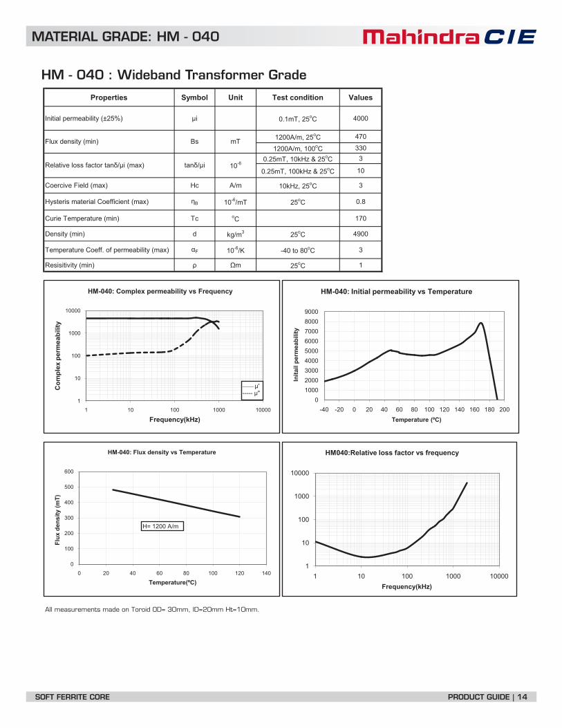
MATERIAL GRADE: HM - 040
HM - 040 : Wideband Transformer Grade
Properties Symbol Unit Test condition Values
Initial permeability (±25%) i 0.1mT, 25oC 4000
1200A/m, 25oC 470
1200A/m, 100oC 3300.25mT, 10kHz & 25oC 3
0.25mT, 100kHz & 25oC 10
m/AcH)xam( dleiF evicreoC 10kHz, 25oC 3
Hysteris material Coefficient (max) B 10-6/mT 25oC 0.8
cT)nim( erutarepmeT eiruC oC 170
d)nim( ytisneD kg/m3 25oC 4900
Temperature Coeff. of permeability (max) F 10-6/K -40 to 80oC 3
Resisitivity (min) m 25oC 1
All measurements made on Toroid OD= 30mm, ID=20mm Ht=10mm.
Relative loss factor tan / i (max) tan / i 10-6
TmsB)nim( ytisned xulF
1
10
100
1000
10000
1 10 100 1000 10000
Com
plex
per
mea
bilit
y
Frequency(kHz)
HM-040: Complex permeability vs Frequency
_____ μ'----- μ"
0100020003000400050006000700080009000
-40 -20 0 20 40 60 80 100 120 140 160 180 200
Inita
il pe
rmea
bilit
y
Temperature (ºC)
HM-040: Initial permeability vs Temperature
0
100
200
300
400
500
600
0 20 40 60 80 100 120 140
Flux
den
sity
(mT)
Temperature(ºC)
HM-040: Flux density vs Temperature
H= 1200 A/m
1
10
100
1000
10000
1 10 100 1000 10000Frequency(kHz)
HM040:Relative loss factor vs frequency
SOFT FERRITE CORE PRODUCT GUIDE | 14

MATERIAL GRADE : HM - 045
HM - 045 : CFL Transformer
Properties Symbol Unit Test condition Values
Initial permeability (±25%) i 0.1mT, 25oC 4500
1200A/m, 25oC 470
1200A/m, 100oC 3300.25mT, 10kHz & 25oC 3
0.25mT, 100kHz & 25oC 10
m/AcH)xam( dleiF evicreoC 10kHz, 25oC 3
cT)nim( erutarepmeT eiruC oC 170
d)nim( ytisneD kg/m3 25oC 4900
Temperature Coeff. of permeability (max) F 10-6/K -40 to 80oC 2.5
All measurements made on Toroid OD= 22mm, ID=14mm Ht=6mm.
Relative loss factor tan / i (max) tan / i 10-6
TmsB)nim( ytisned xulF
1
10
100
1000
10000
1 10 100 1000 10000
Com
plex
Per
mea
bilit
y
Frequency (kHz)
HM045: Complex permeability vs frequency
____μ'-----μ"
0
2000
4000
6000
8000
10000
12000
14000
-40 -20 0 20 40 60 80 100 120 140 160 180 200
Initi
al P
erm
eabi
lity
Temperature (ºC)
HM045: Initial permeability vs temperature
0
100
200
300
400
500
600
0 20 40 60 80 100 120 140
Flux
den
sity
(mT)
Temperature(ºC)
HM045: Flux density vs temperature
1
10
100
1000
10000
1 10 100 1000 10000Frequency(kHz)
HM045:Relative loss factor vs frequency
SOFT FERRITE CORE PRODUCT GUIDE | 15

MATERIAL GRADE: GQ - 5C
GQ - 5C : Wideband Transformer Grade
Properties Symbol Unit Test condition Values
Initial permeability (±25%) i 0.1mT, 25oC 5000
1200A/m, 25oC 450
1200A/m, 100oC 3000.25mT, 10kHz & 25oC 3
0.25mT, 100kHz & 25oC 15
m/AcH)xam( dleiF evicreoC 10kHz, 25oC 3
Hysteris material Coefficient (max) B 10-6/mT 25oC 0.8
cT)nim( erutarepmeT eiruC oC 140
d)nim( ytisneD kg/m3 25oC 4900
Temperature Coeff. of permeability (max) F 10-6/K -40 to 80oC 3
Resisitivity (min) m 25oC 1
All measurements made on Toroid OD= 30mm, ID=20mm Ht=10mm.
Relative loss factor tan / i (max) tan / i 10-6
TmsB)nim( ytisned xulF
10
100
1000
10000
1 10 100 1000 10000
Com
plex
per
mea
bilit
y
Frequency(kHz)
Complex permeability vs Frequency
μ'
μ"0
100020003000400050006000700080009000
10000
-60 -40 -20 0 20 40 60 80 100 120 140 160 180
Initi
al p
erm
eabi
lity
Temperature (ºC)
Initial permeability vs Temperature
1
10
100
1000
10000
1 10 100 1000 10000f(kHz)
Relative loss factor vs frequency
0
100
200
300
400
500
0 20 40 60 80 100 120 140
Flux
den
sity
(mT)
Temperature(degC)
Flux density vs Temperature
H = 1200 A/m
SOFT FERRITE CORE PRODUCT GUIDE | 16

MATERIAL GRADE: HM - 060
HM - 060 : Wideband Transformer Grade Properties Symbol Unit Test condition Values
Initial permeability (±25%) i 0.1mT, 25oC 6000
1200A/m, 25oC 400
1200A/m, 100oC 2400.25mT, 10kHz & 25oC 5
0.25mT, 100kHz & 25oC 40
m/AcH)xam( dleiF evicreoC 10kHz, 25oC 5
Hysteris material Coefficient (max) B 10-6/mT 25oC 0.6
cT)nim( erutarepmeT eiruC oC 130
d)nim( ytisneD kg/m3 25oC 4900
Temperature Coeff. of permeability (max) F 10-6/K -40 to 80oC 2
Resisitivity (min) m 25oC 0.6
All measurements made on Toroid OD= 30mm, ID=20mm Ht=10mm.
Relative loss factor tan / i (max) tan / i 10-6
TmsB)nim( ytisned xulF
1
10
100
1000
10000
1 10 100 1000 10000
Com
plex
per
mea
bilit
y
Frequency(kHz)
HM060: Complex permeability vs Frequency
___ μ'----- μ"
1
10
100
1000
10000
1 10 100 1000 10000Frequency(kHz)
HM-060: Relative loss factor vs frequency
0
2000
4000
6000
8000
10000
12000
-60 -40 -20 0 20 40 60 80 100 120 140 160 180
Initi
al p
erm
eabi
lity
Temperature (ºC)
HM060: Initial permeability vs Temperature
0
50
100
150
200
250
300
350
400
450
0 20 40 60 80 100 120 140
Flux
den
sity
(mT)
Temperature(ºC)
HM060: Saturation flux density vs Temperature
H= 1200 A/m
SOFT FERRITE CORE PRODUCT GUIDE | 17

MATERIAL GRADE: HM - 070
HM - 070 : Wideband Transformer Grade
Properties Symbol Unit Test condition Values
Initial permeability (±25%) i 0.1mT, 25oC 7000
1200A/m, 25oC 400
1200A/m, 100oC 2400.25mT, 10kHz & 25oC 5
0.25mT, 100kHz & 25oC 60
m/AcH)xam( dleiF evicreoC 10kHz, 25oC 4
Hysteris material Coefficient (max) B 10-6/mT 25oC 0.5
cT)nim( erutarepmeT eiruC oC 120
d)nim( ytisneD kg/m3 25oC 4900
Temperature Coeff. of permeability (max) F 10-6/K -40 to 80oC 2
Resisitivity (min) m 25oC 0.5
All measurements made on Toroid OD= 30mm, ID=20mm Ht=10mm.
Relative loss factor tan / i (max) tan / i 10-6
TmsB)nim( ytisned xulF
0
2000
4000
6000
8000
10000
12000
-60 -40 -20 0 20 40 60 80 100 120 140 160
Initi
al p
erm
eabi
lity
Temperature (ºC)
HM070: Initial permeability vs Temperature
100
1000
10000
1 10 100 1000 10000 100000
Com
plex
per
mea
bilit
y
Frequency(kHz)
HM070: Complex permeability vs Frequency
_____ μ'----- μ"
1
10
100
1000
10000
100000
1 10 100 1000 10000Frequency(kHz)
HM-070: Relative loss factor vs frequency
0
50
100
150
200
250
300
350
400
450
0 20 40 60 80 100 120 140
Flux
den
sity
(mT)
Temperature(ºC)
HM070: Flux density vs Temperature
H=1200A/m
SOFT FERRITE CORE PRODUCT GUIDE | 18

MATERIAL GRADE: HM - 100
Properties Symbol Unit Test condition Values
Initial permeability (±25%) i 0.1mT, 25oC 10000
1200A/m, 25oC 430
1200A/m, 100oC 240
0.25mT, 10kHz & 25oC 3
0.25mT, 100kHz & 25oC 20
cT)nim( erutarepmeT eiruC oC 120
d)nim( ytisneD kg/m3 25oC 4900
Temperature Coeff. of permeability (max) F 10-6/K -40 to 80oC 2
Resisitivity (min) m 25oC 0.5
All measurements made on Toroid OD= 10mm, ID=06mm Ht=04mm
HM - 100 : For Wideband Transformer Application
Relative loss factor tan / i (max) tan / i 10-6
TmsB)nim( ytisned xulF
0
5000
10000
15000
20000
25000
-20 0 20 40 60 80 100 120 140
Initi
al p
erm
eabi
lity
Temperature (ºC)
Initial permeability vs temperature
1
10
100
1000
10000
100000
1 10 100 1000
Com
plex
per
mea
bilit
y
Frequency(kHz)
Complex permeability vs frequency
μ'
μ"
1
10
100
1000
1 10 100 1000Frequency(kHz)
Relative loss factor vs frequency
050
100150200250300350400450500
0 20 40 60 80 100 120 140
Flux
den
sity
(mT)
Temperature(ºC)
Saturation flux density vs temperature
10mm
04mm
06mm
Typical Inductance factor (AL) = 4100 +/- 10% nH
Typical DimensionOD = 10+/-0.6mmID = 06+/-0.4mmHt = 04+/-0.2mm
SOFT FERRITE CORE PRODUCT GUIDE | 19

MATERIAL GRADE: HT - 08
HT - 08 :
Properties Symbol Unit Test condition Values
Initial permeability (±25%) i 0.1mT, 25oC 800
1200A/m, 25oC 430
1200A/m, 100oC 3200.25mT, 10kHz & 25oC 10
0.25mT, 100kHz & 25oC 10
m/AcH)xam( dleiF evicreoC 10kHz, 25oC 20
cT)nim( erutarepmeT eiruC oC 190
d)nim( ytisneD kg/m3 25oC 4850
Temperature Coeff. of permeability (max) F 10-6/K -40 to 80oC ±3
Resisitivity (min) m 25oC 10
All measurements made on Toroid OD= 30mm, ID=20mm Ht=10mm.
Relative loss factor tan / i (max) tan / i 10-6
TmsB)nim( ytisned xulF
1
10
100
1000
1 10 100 1000 10000
Com
plex
Per
mea
bilit
y
Frequency(kHz)
HT-08: Complex permeability vs frequency
____μ'-----μ"
0200400600800
10001200140016001800
-40 -20 0 20 40 60 80 100 120 140 160 180 200
Initi
al P
erm
eabi
lity
Temperature (ºC)
HT-08: Initial permeability vs temperature
0
100
200
300
400
500
600
0 20 40 60 80 100 120 140
Flux
den
sity
(mT)
Temperature(ºC)
HT-08: Flux density vs temperature
H = 1200 A/m
1
10
100
1000
10000
100000
1000000
1 10 100 1000 10000Frequency(kHz)
HT-08: Relative loss factor vs frequency
SOFT FERRITE CORE PRODUCT GUIDE | 20

MATERIAL GRADE: HT - 020
HT - 020 : RFID antenna grade
Properties Symbol Unit Test condition Values
Initial permeability (±25%) i 0.1mT, 25oC 2000
1200A/m, 25oC 470
1200A/m, 100oC 3300.25mT, 10kHz & 25oC 6
0.25mT, 100kHz & 25oC 10
m/AcH)xam( dleiF evicreoC 10kHz, 25oC 14
Hysteris material Coefficient (max) B 10-6/mT 25oC 2
cT)nim( erutarepmeT eiruC oC 170
d)nim( ytisneD kg/m3 25oC 4850
Temperature Coeff. of permeability (max) F 10-6/K -40 to 80oC ±0.4
Resisitivity (min) m 25oC 1
All measurements made on Toroid OD= 30mm, ID=20mm Ht=10mm.
Relative loss factor tan / i (max) tan / i 10-6
TmsB)nim( ytisned xulF
1
10
100
1000
10000
1 10 100 1000 10000
Com
plex
per
mea
bilit
y
Frequency(kHz)
HT-020: Complex permeability vs frequency
___ μ'----- μ"
0
1000
2000
3000
4000
-60 -20 20 60 100 140 180 220
Initi
al p
erm
eabi
lity
Temperature (ºC)
HT-020: Initial permeability vs temperature
1
10
100
1000
10000
1 10 100 1000 10000
Frequency (kHz)
HT-020: Relative loss factor vs frequency
0
100
200
300
400
500
600
-40 -20 0 20 40 60 80 100 120
Flux
den
sity
(Bs)
Temperature (ºC)
HT-020: Flux density vs temperature
H= 1200 A/m
SOFT FERRITE CORE PRODUCT GUIDE | 21

MATERIAL GRADE: HT - 35
HT - 35 : RFID antenna grade
Properties Symbol Unit Test condition Values
Initial permeability (±25%) i 0.1mT, 25oC 3400
1200A/m, 25oC 510
1200A/m, 100oC 390
Relative loss factor tan / i (max) tan / i 10-6 0.25mT, 10kHz & 25oC 3
Permanent flux TmrBytisned 25oC 90
m/AcHecrof evicreoC 25oC 10
cT)nim( erutarepmeT eiruC oC 150
d)nim( ytisneD kg/m3 25oC 4800
Temperature Coeff. of permeability (max) F 10-6/K -40 to 80oC 2
Resisitivity (min) m 25oC 1
All measurements made on Toroid OD= 30mm, ID=20mm Ht=10mm.
TmsB)nim( ytisned xulF
0
1000
2000
3000
4000
5000
6000
-60 0 60 120 180 240
Initi
al P
erm
eabi
lity
Temperature (0C)
HT-35 : Initial Permeability Vs Temperature
0
100
200
300
400
500
600
0 20 40 60 80 100 120 140
Flux
Den
sity
(mT)
Temperature (0C)
HT-35 : Flux Density Vs Temperature
1
10
100
1000
10000
100000
10 100 1000 10000
Perm
eabi
lity
Frequency (KHz)
HT-35: Complex Permeability Vs Frequency
SOFT FERRITE CORE PRODUCT GUIDE | 22

MATERIAL GRADE: HR - 4
HR - 4 : Ferrite Impeder GradeProperties Symbol Unit Test condition Values
Initial permeability (±25%) i 0.1mT, 25oC 1200
1200A/m, 25oC 440
1200A/m, 100oC 350
m/AcH)xam( dleiF evicreoC 10kHz, 25oC 10
cT)nim( erutarepmeT eiruC oC 240
d)nim( ytisneD kg/m3 25oC 4800
Resisitivity (min) m 25oC 4
400kHz/200mT/250C 10000
400kHz/200mT/1000C 7000
All measurements made on Toroid OD= 30mm, ID=20mm Ht=10mm.
cc/WmcP)xam( ssolrewoP
TmsB)nim( ytisned xulF
0
100
200
300
400
500
0 20 40 60 80 100 120 140
Flux
den
sity
(mT)
Temperature(ºC)
Saturation flux density vs temperature
H= 1200 A/m
1
10
100
1000
10000
1 10 100 1000 10000
m',m
"
Frequency(kHz)
HR4: Complex permeability vs Frequency
μ'
μ"0
1000
2000
3000
-60 0 60 120 180 240
μi
Temperature (ºC)
Initial permeabiltiy vs temperature
400045005000550060006500700075008000
20 30 40 50 60 70 80 90 100 110 120 130
Rela
tive
core
loss
( m
W/c
c)
Temperature(ºC)
Relative core losses vs temperature
400kHz / 200mT
SOFT FERRITE CORE PRODUCT GUIDE | 23

MATERIAL GRADE: HR - 4B
Properties Symbol Unit Test condition Values
Initial permeability (±25%) i 0.1mT, 25oC 2000
1200A/m, 25oC 500
1200A/m, 100oC 400
m/AcH)xam( dleiF evicreoC 10kHz, 25oC 10
cT)nim( erutarepmeT eiruC oC 210
d)nim( ytisneD kg/m3 25oC 4800
Resisitivity (min) m 25oC 4
400kHz/200mT/250C 8000
400kHz/200mT/1000C 6000
All measurements made on Toroid OD= 30mm, ID=20mm Ht=10mm.
cc/WmcP)xam( ssolrewoP
HR - 4B : Ferrite Impeder Grade
TmsB)nim( ytisned xulF
1
10
100
1000
10000
1 10 100 1000 10000
Com
plex
per
mea
bilit
y
f(kHz)
HR4B: Complex permeability vs frequency
___ μ'----- μ"
4000
4500
5000
5500
6000
6500
20 40 60 80 100 120 140
Rela
tive
core
loss
(mW
/cc)
Temperature(ºC)
HR4B: Relative core losses vs Temperature
400kHz / 200mT0
100
200
300
400
500
600
0 20 40 60 80 100 120 140
Flux
den
sity
(mT)
Temperature(ºC)
HR4B: Saturation flux density vs temperature
H= 1200 A/m
0
1000
2000
3000
4000
5000
-40 -20 0 20 40 60 80 100 120 140 160 180 200 220 240
Initi
al p
erm
eabi
lity
Temperature (ºC)
HR-4B: Initial permeability vs temperature
SOFT FERRITE CORE PRODUCT GUIDE | 24

MATERIALGRADE: HQ - 023
HQ - 023 : High Q Inductors
Properties Symbol Unit Test condition Values
Initial permeability (±25%) i 0.1mT, 25oC 2300
1200A/m, 25oC 420
1200A/m, 100oC 2900.25mT, 10kHz & 25oC 4
0.25mT, 100kHz & 25oC 6
m/AcH)xam( dleiF evicreoC 10kHz, 25oC 25
cT)nim( erutarepmeT eiruC oC 170
d)nim( ytisneD kg/m3 25oC 4700
Temperature Coeff. of permeability (max) F 10-6/K -40 to 80oC 3
All measurements made on Toroid OD= 30mm, ID=20mm Ht=10mm.
Relative loss factor tan / i (max) tan / i 10-6
TmsB)nim( ytisned xulF
1
10
100
1000
10000
1 10 100 1000 10000Frequency(kHz)
HQ-023: Relative loss factor vs frequency
1
10
100
1000
10000
1 10 100 1000 10000
Com
plex
Per
mea
bilit
y
Frequency(kHz)
HQ-023: Complex permeability vs frequency
____μ'-----μ"
0
500
1000
1500
2000
2500
3000
3500
4000
-40 -20 0 20 40 60 80 100 120 140 160 180 200 220
Initi
al P
erm
eabi
lity
Temperature (ºC)
HQ-023: Initial permeability vs temperature
0
100
200
300
400
500
0 20 40 60 80 100 120 140
Flux
den
sity
(mT)
Temperature(ºC)
HQ-023: Flux density vs temperature
SOFT FERRITE CORE PRODUCT GUIDE | 25

DIMENSIONS
E E CORES
Type A(mm) BB(mm) CC(mm) DD(mm) EE (mm) FF (mm) 2 3mm mm mm MSB-5S MSB-7C MGQ5C HP 400 gms/pair+ 2.3 +0.0 +0.0 +2.4 +0.0E100/60/28 100 60.00 28.00 72.00 28.00 46.00 270 785 212000 --- 5900 --- 5900 2040- 1.7 -1.1 -0.8 -0.0 -1.0 -0.0
EE80/38/20 80.00 ± 1.6 38.1 ±0.5 19.8 ±0.4 59.1 Min 19.8 ±0.4 28.2 ± 0.5 184 395 72300 --- 6700 --- 5000 360+0.0 +0.0 +1.5 +0.0 +0.7EE70/33/32 70.5 ± 1 33.2 32.00 48.00 22.00 21.9 149 683 102000 --- 10800 --- 8000 550-0.5 -0.8 -0.0 -0.7 -0.0
+ 1.5 +0.0 +0.0 +1.5 +0.0 +0.8EE 65X33X28 65.00 32.80 27.40 44.20 20.00 22.20 147 532 78200 --- 5550 --- --- 400-1.2 -0.6 -0.8 -0.0 -0.7 -0.0+ 1.5 +0.0 +0.0 +1.5 +0.0 +0.8EE 65X33X13 65.00 32.80 13.70 44.20 20.00 22.20 147 267 39350 6300 4500 --- --- 191- 1.2 -0.6 -0.6 -0.0 -0.7 -0.0+ 1.2 +0.0 +0.0 +1.2 +0.0 +0.8EE 55X27X21 55.00 27.80 21.00 37.50 17.20 18.50 120 354 42500 7900 6000 --- --- 214- 0.9 -0.6 -0.6 -0.0 -0.5 - 0.0+ 1.0 +0.0 +0.0 +1.2 +0.0 +0.7EE 42X21X20 42.00 21.20 20.00 29.50 12.20 14.80 98 236 23100 6400 5200 --- --- 113- 0.7 -0.4 -0.8 -0.0 -0.5 -0.0+ 1.0 +0.0 +0.0 +1.2 +0.0 +0.7EE 42X21X15 42.00 21.20 15.20 29.50 12.20 14.80 97 182 17650 5250 4000 --- --- 86- 0.7 -0.4 -0.5 -0.0 -0.5 -0.0+ 1.0 +0.0 +0.0 +1.2 +0.0 +0.7EE 42X21X9 42.00 21.20 9.00 29.50 12.20 14.80 97 107 10400 2900 2300 --- --- 51- 0.7 -0.4 -0.5 -0.0 -0.5 -0.0+ 0.7 +0.6 +0.0 +0.7 +0.0 +0.6EE 41X17X12 41.00 17.50 12.00 28.50 12.00 10.25 78.45 147 11563 5100 4100 --- --- 56- 0.5 -0.0 -0.7 -0.0 -0.7 -0.0
+0.5 +0.0 +1.2 +0.0 +0.5EE 36X11X18 36.20 ±0.5 18.00 11.50 24.50 10.20 12.00 81 120 9670 4000 3100 --- --- 50 -0.0 -0.5 -0.0 -0.5 -0.0EE 35X14X9 34.90 ±0.7 14.50±0.25 9.15 ±0.25 25.75±0.5 9.20 ±0.25 10.00±0.25 70 83 5870 3300 2650 --- --- 30
05.0+0.0+0.0+5.0+EE 33X16X13 33.00±0.5 16.50 13.00 23.40 min 10.00 12.00 76.6 118 8970 --- --- --- --- 450.0-6.0-6.0-0.0-05.0+0.0+0.0-5.0-EE33X14X13 33.00±0.5 14.00 13.00 23.40 min 10.00 9.50 67 118 7960 4700 3900 --- --- 430.0-6.0-6.0-0.0+53.0+0.0+0.0+5.0+EE33X15X7 30.15±0.35 15.20 7.10 20.00 min 7.05 10.05 66 57 3810 2730 2100 3300 --- 21.60.0-4.0-4.0-53.0-5.0+0.0+8.0+5.0+8.0 +EE 25X13X11 25.00 12.5 10.50±0.25 17.50 7.50 8.95 57 76 4400 3800 3050 --- --- 23.10.0-5.0-0.0-0.0-7.0 -6.0+3.0 +0.0+6.0+5.0 +EE 25X16X7 25.30 15.70 6.80 19.20 min 6.50 12.55 73.5 42.0 3120 1685 --- --- --- 15.40.0-52.0-4.0-0.0-3.0-
+ 0.8 +0.0 +0.0 +0.8 +0.0 +0.5EE 25X13X7 25.00 12.80 7.50 17.50 7.50 8.70 57.5 52.5 3020 2625 2100 2600 8000 16.5- 0.7 -0.5 -0.6 -0.0 -0.5 -0.0+0.0 +0.0 +1.2 +0.0 +0.4EE 25X9X6 25.40 ±0.7 9.70 6.55 19.00 6.55 6.30 48 40 1950 2248 2000 2400 --- 10-0.4 -0.5 -0.0 -0.5 -0.0+0.0 +0.0 +0.6 +0.0 +0.4EE20X10X5 20.15±0.55 10.20 5.30 12.80 5.20 6.30 42.8 31.2 1340 1900 1560 2745 --- 8-0.4 -0.4 -0.0 -0.4 -0.0
+ 0.0 +0.0 +0.0 +0.8 +0.0 +0.4EE20X10X5-M 20.40 10.10 5.90 14.10 5.90 7.00 44.90 33.50 1500 --- --- --- 1450 7.4- 0.8 -0.4 -0.5 -0.0 -0.4 -0.00.0+0.0+EE 19X8X5 19.30 ±0.3 7.90 ±0.2 5.20 14.00 ±0.3 5.20 5.50 ±0.2 37 22.20 822 --- --- 1500 --- 4.75.0-5.0-
+0.0EE16X12X5 16.00 ±0.4 12.40 ±0.3 5.10 12.0 ±0.3 3.90 ±0.3 10.40 ±0.3 56.40 19.0 1060 --- --- --- --- 5-0.5+ 0.7 +0.0 +0.0 +0.6 +0.0 +0.4EE16X8X5 16.00 8.20 4.70 11.30 4.70 5.70 37 20.10 750 1500 1100 1470 --- 4- 0.5 -0.3 -0.4 -0.0 -0.3 -0.0
0.0+0.0+0.0+EE 12.65 12.65`±0.45 6.50 3.70 9.20 ±0.3 200110087636.927.9206.4.0±07.3 3.0-3.0-2.0-
Le Ae Ve AL VALUE ( ±25%) Almin Approx wt
+1.7
CF
B
E AD
Application of EE Cores
Small E CoreImpedance matching tranformerFor Miniature TranformersSMD Tranformers
Large E CoreCommom mode choke and broadband transformersFor SMPSEnergy storage chokes
DIMENSIONS
SOFT FERRITE CORE PRODUCT GUIDE | 26

EER , EC , ETD , EED , EEH CORES
Type A(mm) B(mm) C(mm) D(mm) E (mm) F (mm)EC35 35.00 ± 0.5 22.6 ± 0.3 11.30 ± 0.3 25.60 +1.0/-0 11.30 ± 0.30 16.60 ± 0.30EC40A 40.00 ± 0.5 24.2 ± 0.3 13.40 ± 0.3 29.00 +1.0/-0 13.30 ± 0.25 17.20 ± 0.30EC40B 40.00 ± 0.5 22.8 ± 0.3 13.40 ± 0.3 29.00 +1.0/-0 13.30 ± 0.25 15.80 ± 0.30EC40C 40.00 ± 0.5 22.5 ± 0.3 13.40 ± 0.3 29.00 +1.0/-0 13.30 ± 0.30 15.50 ± 0.30EC42 42.00 ± 0.5 22.4 +0.4/-0.2 15.50 ± 0.3 29.40 Min 75.5 +0.2/-0.4 15.40 ± 0.30EC90 90.00 ± 1.80 45.0 +0.65 30.00 ± 1.00 70.00 ± 1.50 30.00 ± 1.00 35.00 ± 0.50EC120 120.00 ± 2.0 50.9 ± 0.5 30.00 ± 0.50 90.00 Min 30.00 ± 0.5 35.70 ± 0.50EER0905 9.35 ± 0.15 2.45 ± 0.10 4.90 ± 0.1 7.50 Min 3.4 ± 0.10 1.675 ± 0.15EER1105 10.85 ± 2.0 2.45 ± 0.10 5.90 ± 0.15 8.85 ± 0.2 4.125 ± 0.125 1.575 ± 0.10
EER1717 17.50 ± 0.35 8.50 ± 0.20 5.00 ± 0.2 13.60 ± 0.35 5.0 ± 0.15 6.30 ± 0.15EER2622 25.50 ± 0.50 11.0 ± 0.20 7.50 ± 0.2 19.80 Min 7.5 ± 0.15 7.90 ± 0.20EER28-A 28.50 +0.6/-0.5 17.3 +0/-0.6 11.4 ± 0.3 21.2 +1.0/-0 9.9 ± 0.30 12.25 +0.6/-0EER28-B 28.50 ± 0.6 15.6 +0/-0.6 11.4 ± 0.3 21.2 +1.0/-0 9.9 ± 0.30 10.55 +0.6/-0EER28-C 28.50 +0.6/-0.5 12.8 +0.6/-0 11.4 ± 0.3 21.2 +1.0/-0 9.9 ± 0.30 8.40 +0.6/-0EER3019 30.00 ± 0.8 15.3 ± 0.2 11.3 ± 0.2 25.6 Min 11.3 ± 0.20 10.80 ± 0.3EER42X20 42.15 ± 0.65 21.2 ± 0.2 19.6 ± 0.4 32.3 ± 0.5 17.3 ± 0.25 15.00 ± 0.5/0EER42X17 42.00 +0.8/-0.5 25.7 ± 0.2 17.3 ± 0.3 30.3 ± 0.5 17.3 ± 0.25 18.2 ± 0.2ETD29 30.60 +0.0/-0.6 16.0 +0/-0.4 9.8 +0/-0.6 22.0 +1.4/-0 9.8 +0/-0.6 10.70 +0.6/-0ETD34 34.00 +0.0/-0.6 17.5 +0/-0.4 11.1 +0/-0.6 25.6 +1.4/-0 11.1 +0/-0.6 11.80 +0.5/-0ETD39 38.90 +1.1/-0.7 20.0 +0/-0.4 12.8 +0/-0.6 29.3 +1.6/-0 12.8 +0/-0.6 14.20 + 0.8/-0ETD39 38.90 +1.1/-0.7 22.4 +0/-0.4 12.8 +0/-0.6 29.3 +1.6/-0 12.8 +0/-0.6 16.75 ± 0.5ETD44 44.00 ± 1.0 22.3 ± 0.3 14.8 ± 0.4 33.8 ± 0.8 14.8 ± 0.40 16.50 ± 0.4ETD49 48.50 +1.1/-0.9 24.9 +0/-0.4 16.7 +0/-0.6 36.0 ± 1.8/0 16.7 +0/-0.6 17.70 +0.8/-0.0ETD54 54.5 ± 1.3 27.6 +0/-0.4 18.90 ± 0.4 41.2 ± 1.1 18.9 ± 0.4 20.2 ± 0.4ETD5922 59.80 ± 1.4 31.2 +0/-0.4 22.1 +0/-0.9 43.6 +2.2/-0 22.1 +0/-0.9 22 +0.9/-0EEH2820 28.00 ± 0.30 10.2 ± 0.2 11.9 ± 0.15 20.5 Min 8.5 ± 0.15 6.60 ± 0.1EEH2929 29.30 ± 0.30 14.6 ± 0.20 11.6 ± 0.20 21.6 Min 8.4 ± 0.2 11.5 ± 0.2EEH3311 33.00 ± 0.30 10.5 ± 0.2 13 ± 0.3 23.3 Min 10.5 ± 0.2 5.85 ± 0.15EE4215 42.5 ± 0.5 21.4 ± 0.3 14.8 ± 0.3 31.15 Min 14.8 ± 0.3 15.4 ± 0.3
DIMENSIONS
A
B
F
C
DE
Application of EER ,EC , ETD , EED , EEHFor High inductance and low heightCompact TransformersCompact winding design with low leakage currentsFlyback converter for TV and monitorsSwitch mode power suppliesConstant area of cross sectionalong the magnetic path
Type A B C D E FLe Ae Ve AL VALUE ( ±25%) Almin Approx wt
C
SOFT FERRITE CORE PRODUCT GUIDE | 27

Type A B C D E F G
EER , EC , ETD , EED , EEH CORES
32Type Wt (gm) Le (mm) Ae (mm ) Ve (mm ) AL± 25%EC35 55 93.8 107.0 10036 2650EC40A 82 101.7 148.0 15050 3150EC40B 79 93.8 143.0 13413 3200EC40 C 77 93.6 148.0 13852 3450EC42 102 98.8 194.0 19167 4100EC90 656 216.0 624.0 134784 7100EC120 975 26.00 7.730 205810 8000EER0905 0.60 13.4 8.8 116 800EER 1105 0.9 14.2 12.13 172 1400EER 1717 4.40 41.2 20.0 827 930EER 2622 11.20 54.1 44.3 2390 1880EER28-A 34 78.3 85.0 6640 2850EER28-B 35 64.0 85.0 5444 3200EER28-C 25 54.5 83.8 4568 3200EER3019 29 45.2 135.3 6100 5900EER42X20 113 98.6 240.0 23664 3900EER42X17 136 113.6 239.0 27180 4200ETD29 28 70.4 76.0 5350 2100ETD34 40 78.6 97.1 7632 2800ETD39 61 92.1 125.0 11510 3200ETD39 63 103.2 121.3 12531 3200ETD44 94 103.0 173.0 17900 3700ETD49 124 114.0 211.0 24050 4000ETD 54 180 127 280 35500 5000ETD5922 258 139.0 368.0 51500 6000EEH2820 22 51.7 87.8 4688 3840EEH2929 29.4 69.2 90 6220 3300EEH3311 32.7 52.08 120.7 6289 3200EER42/15 85 100.12 166 16591 ---
SOFT FERRITE CORE PRODUCT GUIDE | 28

EI CORES
Application od EI coresTransformers for SMPSImpedance matching TransformersMiniature and SMD transformers
Type A(mm) BB(mm) CC(mm) DD(mm) EE (mm) FF (mm) GG(mm)+ 0.1EI1614 16 ± 0.3 14.5 ± 0.5 4.8 11.7 Min 3.8 ± 0.2 10.4 ± 0.2 2 ± 0.2- 0.2
+ 0.8 + 01EI1916 19.2 ± 0.4 15.2 5.50 14 Min 5.1 +0/-0.50 10.5 ± 0.3 2.4 ± 0.2- 0.4 - 0.2
+ 0.00EI2218 22.00 ± 0.6 19 ± 0.5 6.00 15.6 Min 6.1 +0/-0.50 11 ± 0.3 4.00 ± 0.3- 0.50
04.0+07.0+05.0+EI2519 25.00 19.30 6.50 ± 0.30 17.80 Min 6.50 ± 0.25 13.00 3.30 ± 0.3000.0-03.0-03.0-05.0+00.0+00.0+03.0+EI2820 28.00 ± 0.50 20.20 11.00 18.60 Min 7.50 12.20 3.50 ± 0.3000.0-06.0-06.0-08.0-
00.0+02.0+EI2820 A 28.00 ± 0.50 20.80 ± 0.60 11.00 18.60 Min 7.50 12.80 ± 0.30 3.50 ± 0.3006.0-03.0-
+ 0.70 + 0.60 + 0.0 + 0.70 + 0.00 + 0.60EI3026 30.00 26.50 11.00 20.00 11.00 16.00 5.50 ± 0.20- 0.00 00.0-07.0-00.0-07.0-02.0-05.0+00.0+00.0+± 0.50EI3329 33.00 ± 0.50 28.75 13.00 23.40 Min 10.00 19.00 5.00 ± 0.3000.0-06.0-06.0-06.0+00.0+00.0+09.0+08.0+EI3530 35.00 29.60 12.00 25.30 Min 10.30 18.30 5.50 ± 0.2000.0-06.0-06.0-02.0-05.0-
+ 0.80 + 0.00 + 0.70 + 0.00 + 0.50EI4035 40.00 ± 0.50 3500 1200 27.50 12.00 20.20 7.50 ± 0.30- 0.30 - 0.70 - 0.00 - 0.70 - 0.00
00.1+07.0+57.0+EI5042 50.10 ± 1.00 42.05 14.70 ± 0.40 34.50 14.60 ± 0.40 24.50 9.00 ± 0.2500.0-00.0-52.0-
EI7026 70.00 ± 1.50 56.00 ± 1.00 19.50 ± 0.50 50.00 ± 0.50 19.50 ± 0.50 35.50 ± 0.50 10.50 ± 0.50
B
F
E
C
D
G
A
DIMENSIONS
SOFT FERRITE CORE PRODUCT GUIDE | 29

Type A B C D E F G
Type Wt set Le Ae Ve AL± 25%
EI CORES
AL± 25%Type Wt set Le Ae Ve
32Gm mm mm mm MSB7C MSB5S
EI1614 3.70 35.3 190 660 385 400
EI1916 4.7 38.16 25.5 976 600 670
EI2218 8 41 36 1476 1600 1600
EI2519 10.20 47.1 42.0 1980 2100 2500
EI2820 22.00 48.9 86.0 4140 50006500 min
EI2820 A 23.00 49.5 86.5 4195 InMGQ5CEI3026 34.00 58.6 110.0 6440 4000 3900
EI3329 42.00 67.5 119.0 8040 3700 5200
EI3530 41.50 67.3 120.0 8076 4000 4800
EI4035 60.30 77.1 147.0 11370 4500 5400
EI5042 110.90 95.4 226.4 21599 1500 1500
EI7026 257.40 133.0 390.0 51870 1500 2010
AL Values : nH ±25% 1KHz 0.1V 100Ts
EFFECTIVE PARAMETERS
SOFT FERRITE CORE PRODUCT GUIDE | 30

EFD CORES
Application of EFD coresFor DC- DC ConverterFor flat transformers of Lower center legOptimized cross section of LegsGood thermal response in case of Flat type EFDdue optimised distribution of Cross section
A
B
FC
E
G
D
Type A(mm) BB(mm) CC(mm) DD(mm) EE (mm) FF (mm) GG(mm)
EFD1010 10.50 ± 0.3 5.20 ± 0.10 2.70 ± 0.10 7.65 ± 0.25 4.55 ± 0.15 3.75 ± 0.15 1.45 ± 0.05
EFD1212 1250 ± 0.10 6.20 ± 0.10 3.50 ± 0.10 9.00 ± 0.25 5.40 ± 0.15 4.55 ± 0.15 2.00 ± 0.10
EFD1515 15.00 ± 0.40 7.50 ± 0.15 4.65 ± 0.15 11.00 ± 0.35 5.30 ± 0.15 5.50 ± 0.25 2.40 ± 0.10
EFD2020 20 ± 0.55 10.00 ± 0.15 6.65 ± 0.15 15.40 ± 0.50 8.90 ± 0.20 7.70 ± 0.25 3.60 ± 0.15
EFD2525 25.00 ± 0.65 12.50 ± 0.15 9.10 ± 0.20 18.70 ± 0.60 11.40 ± 0.20 9.30 ± 0.25 5.20 ± 0.15
EFD3030 30.00 ± 0.8 15.00 ± 0.20 9.10 ± 0.20 22.40 ± 0.75 14.60 ± 0.25 11.20 ± 0.30 4.90 ± 0.15
EFD4030 40.70 ± 0.8 15.00 ± 0.15 8.00 ± 0.25 28.70 ± 0.60 16.00 ± 0.30 10.00 ± 0.15 5.00 ± 0.15
Type Wt set Le Ae Ve AL± 25%32gm mm mm mm HP400
EFD1010 0.9 23.7 7.2 171 585
EFD1212 1.80 28.5 11.4 325 825
EFD1515 2.8 34.0 15.0 510 950
EFD2020 7.20 47.0 31.0 1460 1300
EFD2525 16 57.0 58.0 3300 2200
EFD3030 24 38.0 69.0 4700 2100
EFD4030 31.00 70.9 82.2 5830 2450
AL Values : nH ± 25% 1KHz 0.1V 100Ts
DIMENSIONS
EFFECTIVE PARAMETERS
AL± 25%Type Wt set Le Ae Ve
SOFT FERRITE CORE PRODUCT GUIDE | 31

Type A B C D E F
Type Wt / set Le Ae Ve Al± 25%
EP CORES
Application od EP coresFor power applicationExcellent properties for broadband transformersFor Transformers featuringhigh Inductance and Low heightExcellent magnetic sheilding
C
F
D AE
B
Type A(mm) BB(mm) CC(mm) DD(mm) EE (mm) FF (mm)
EP5 6.00 ± 0.15 2.80 ± 0.05 3.80 ± 0.10 4.4 ± 0.15 1.70 ± 0.10 200 ± 0.10
EP7 9.40 + 0.00 3.75 ± 0.00 6.50 + 0.00 72 + 0.40 3.40 + 0.00 250 + 0.20- 0.40 - 0.10 - 0.30 - 0.00 - 0.20 - 0.10
EP10 11.50 ± 0.30 5.10 ± 0.10 7.60 ± 0.20 9.8 ± 0.20 3.30 ± 0.15 3.70 ± 0.10
EP13 12.80 + 0.00 6.50 0.00 9.00 + 0.00 9.7 + 0.60 450 + 0.00 450 + 0.20- 0.60 - 0.15 - 0.40 - 0.00 - 0.30 - 0.00
EP17 18.00 ± 0.4 8.4 ± 0.1 11.00 + 0.3 12.0 ± 0.4 5.7 ± 0.18 5.70 ± 0.15
EP20 24.00 ± 0.50 10.7 ± 0.1 15.00 ± 0.4 16.5 ± 0.4 8.8 ± 0.25 7.20 ± 0.15
Type Wt set Le Ae Ve AL± 25%32gm mm mm mm HP400
EP5 0.50 9.7 3.0 28.7 400
EP7 1.40 15.7 10.3 162.0 1100
EP10 2.80 19.2 11.3 217.0 1100
EP13 4.7 24.2 19.5 474.0 1600
EP17 12 29.5 33.7 999.0 2200
EP20 27 41.1 78.7 3230.0 3850
AL Values : nH ± 25% 1KHz 0.1V 100Ts
DIMENSIONS
EFFECTIVE PARAMETERS
SOFT FERRITE CORE PRODUCT GUIDE | 32

EPC CORES
Application od EPC coresFor DC- DC ConverterFor flat transformers of Lower center legOptimized cros section of LegsEMI Suppression ChokesGood thermal response
A
F
B
E D
C
Type A(mm) BB(mm) CC(mm) DD(mm) EE(mm) FF (mm)
EPC1313 13.20 ± 0.25 6.60 ± 0.20 4.60 ± 0.15 8.30 Min 5.6 ± 0.15 4.50 ± 0.20
EPC1716 17.50 ± 0.30 8.55 ± 0.20 6.00 ± 0.20 12 ± 0.50 7.70 ± 0.15 6.05 ± 0.20
EPC1920 19.10 ± 0.40 9.75 ± 0.20 6.00 ± 0.15 13.10 Min 8.50 ±0.15 7.25 +0.2/-0.1
EPC2228 21.90 ± 0.30 14.5 ± 0.20 7.30 ± 0.15 14.70 Min 9.5 ±0.15 11.55 ± 0.15
EPC2225 21.90 ± 0.30 14.20 ± 0.20 7.30 ± 0.15 9.50 ± 0.15 14.70 Min 11.55 ± 0.15
EPC2525 25.40 ± 0.50 12.50 ± 0.25 8.00 ± 0.15 18.35 ± 0.4 10.5 ± 0.25 9.00 ± 0.20
FQKT16.5 16.50 ± 0.30 12.0 ± 0.20 8.70 ± 0.20 5.70 ± 0.10 9.00 ± 0.50 8.60 +0.25/-0.0
FQT17.4 17.40 ± 0.3 11.8 ± 0.10 8.7 ± 0.20 5.70 ± 0.15 10.0 ± 0.50 8.70 ± 0.15
FQKT18 18.00 ± 0.3 11.8 ± 0.20 8.7 ± 0.20 5.70 ± 0.15 10.8 ± 0.50 8.70 ± 0.15
Type Wt / set Le Ae Ve Al± 25%32gm mm mm mm Hp400
07832.16163.882.9129.03131CPE
05017198.222.0426.46171CPE
00974017.221.6402.50291CPE
003103329.6351.3648.218222CPE
093103522.041.3604.215222CPE
0051768281.9337.2561.215252CPE
001108318.131.442.95.61TKQF
051102510.230.8405.94.71TKQF
003105513.230.8408.981TKQF
AL Values : nH ± 25% 1KHz 0.1V 100Ts
DIMENSIONS
EFFECTIVE PARAMETERS
Type A B C D E F
Type Wt set Le Ae Ve AL± 25%
SOFT FERRITE CORE PRODUCT GUIDE | 33

Type Wt set Le Ae Ve AL
Type A B C D E F
EPC CORES
Application od PQ coresCompact TransformersLow distortion broadband transmissionat low signalDC/DC Converters
Type A(mm) BB(mm) CC(mm) DD(mm) EE (mm) FF (mm)
PQ2020 21.3 ± 0.4 10.10 ± 0.1 14.00 ± 0.40 18.00 ± 0.40 8.80 ± 0.20 7.15 ± 0.20
PQ2620 26.50 ± 0.45 10.075 ± 0.125 19.00 ± 0.45 22.50 ± 0.45 12.00 ± 0.20 5.75 ± 0.15
PQ2625 26.50 ± 0.45 12.50 ± 0.25 19.00 ± 0.5 22.50 ± 0.45 12.00 ± 0.20 8.15 ± 0.25
PQ3220 33.00 ± 0.50 10.55 ± 0.20 22.00 ± 0.5 27.50 ± 0.50 13.45 ± 0.25 6.05 ± 0.20
PQ3230 33.00 ± 0.50 15.15 ± 0.15 22.00 ± 0.5 27.50 ± 0.50 13.50 ± 0.25 10.65 ± 0.20
PQ3535 36.10 ± 0.60 17.35 ± 0.125 26.00 ± 0.5 32 ± 0.5 14.4 ± 0.25 12.5 ± 0.15
PQ4040 41.5 ± 0.90 20.00 ± 0.15 28.00 ± 0.6 37.00 ± 0.60 14.90 ± 0.30 14.80 ± 0.20
PQ5050 51.00 ± 0.70 25 ± 0.25 32.00 ± 0.6 44.00 ± 0.70 20.00 ± 0.35 18.05 ± 0.30
Type Wt / set Le Ae Ve AL32 004PHmmmmmmmg
008205826.267.54410202QP
00610.2745.913.5400.030262QP
05440.9997.335.550.635262QP
06360.93690.0717.6534D223QP
0774005210.7617.4726D323QP
07350.822710.6919.780.085353QP
00940.284020.1029.1010.590404QP
0036001730.8230.3115910505QP
A
C
B
D
F
E
EFFECTIVE PARAMETERS
DIMENSIONS
SOFT FERRITE CORE PRODUCT GUIDE | 34

RM CORES
Application of RM coresCompact designLow distortion broadbandtransmission at low signalDC/DC Converters A
D
C
F
B
E
Type Wt set Le Ae Ve AL32gm mm mm mm HP400
RM4 1.7 23.2 13.8 322 1070
RM5 3.3 22.1 23.8 526 1800
RM6 5.0 28.6 36.6 1050 2350
RM8 12.40 38.0 64.0 2430 3300
RM10 22.00 44.0 98.0 4310 4340
RM12 45 56.0 150.0 8400 5400
RM14 74 69.0 206.0 14100 6100
AL Values : nH ± 25% 1KHz 0.1V 100Ts
Type A(mm) BB(mm) CC(mm) DD(mm) EE (mm) FF (mm)
02.0+5.300.0+04.0+00.0+00.0+RM4 11.00 5.20 ± 0.05 4.60 7.95 3.9 00.0-02.0-00.0-02.0-51.0-+ 0.00 + 0.40 + 0.00 3.15 + 0.20RM5 14.9 max 5.20 ± 0.05 6.80 10.20 4.9- 0.40 - 0.00 - 0.20 - 0.00
02.0+00.400.0+05.0+00.0+0.0 +RM6 17.9 6.20 ± 0.05 8.20 12.40 6.40 00.0-02.0-00.0-04.0-7.0 - 02.0+04.500.0+06.0+00.0+0.0 +RM8 23.20 8.20 ± 0.05 11.00 17.00 8.55 00.0-03.0-00.0-05.0-09.0-03.0+02.600.0+09.0+00.0+0+RM10 28.50 9.30 ± 0.05 13.50 21.20 10.9000.0-04.0-00.0-05.0-3.1-03.0+04.800.0+00.1+00.0+0+RM12 37.40 12.25 ± 0.05 16.10 25.00 12.800.0- 04.0-00.0-05.0-3.1-03.0+04.0100.0+02.1+00.0+0+RM14 42.20 15.05 ± 0.05 18.00 29.00 15.0000.0-06.0-00.0-06.0-4.1-
EFFECTIVE PARAMETERS
Type A B C D E F
Type Wt / set Le Ae Ve AL
SOFT FERRITE CORE PRODUCT GUIDE | 35

Type A B C D E
Type Le Ae Ve AL±25%Wt
PLANNER CORES
Application of Planar coresLow profile coreHigh AL ValueHigh core surface to volume ratioExcellent thermal performanceHigh output currents at lowoutput voltageGood EMC characteristics
Type A(mm) BB(mm) CC(mm) DD(mm) EE (mm) FF (mm) GG(mm)
PEE1407 14.00 ± 0.30 3.50 ± 0.10 5.00 ± 0.10 11.0 ± 0.25 3.00 ± 0.05 2.00 ± 0.10 ---
PEE1808 18.00 ± 0.35 4.00 + 0.10 10.00 ± 0.20 14.00 ± 0.30 4.00 ± 0.10 2.00 ± 0.10 ---
PEE2211 21.80 ± 0.40 5.7 ± 0.1 15.80 ± 0.30 16.80 ± 0.40 5.00 ± 0.10 3.20 ± 0.10 ---
PEI1405 14.00 ± 0.30 3.5 ± 0.10 5.00 ± 0.10 11.00 ± 0.25 3.00 ± 0.05 2.00 ± 0.10 1.50 ± 0.05
PEI1806 18.00 ± 0.35 4.00 ± 0.10 10.00 ± 0.20 14.00 ± 0.30 4.00 ± 0.10 2.00 ± 0.10 2.00 ± 0.05
PEI2208 21.8 ± 0.40 5.70 ± 0.10 15.80 ± 0.30 16.80 ± 0.40 5.00 ± 0.10 3.20 ± 0.10 2.50 ± 0.05
PEE6420 64 ± 1.30 10.20± 0.15 50.80 ± 1.10 53.8 ± 1.10 10.2 ± 0.20 5.10 ± 0.15 ---
Type Wt set Le Ae Ve AL±25%32gm mm mm mm HP400
PEE1407 1.20 20.7 14.3 300.0 1280
PEE1808 4.80 24.30 39.3 960 2880
PEE2211 13 32.50 78.3 2550 4800
PEI1405 1.10 16.70 14.50 240 1440
PEI1806 4.10 20.50 39.50 800 3200
PEI2208 10.50 26.10 78.50 2040 5520
PEE6420 200 79.90 519.00 40700 14000
AL Values : nH ± 25% 1KHz 0.1V 100Ts
G
EDA
F
B
C
EFFECTIVE PARAMETERS
DIMENSIONS
SOFT FERRITE CORE PRODUCT GUIDE | 36

UU AND UI CORES
Application of U CoresPulse and High Voltage TransformerLine Deflection transformersEnergy storage chokescommon chokesSuppression for Line Filter
TTypee AA(mm) BB(mm) CC(mm) DD(mm) EE (mm)UU 10 10.00 ± 0.25 14.40 ± 0.4 3.00 +0.0/-0.4 4.30 + 0.4/-0.2 8.60 ± 0.6UU 10.5 10.50 ± 0.25 15.80 ± 0.4 5.35 ± 0.25 5.30 + 0.4/-0.0 10.60 ± 0.3UU 1414 14 ± 0.3 14.2 ± 0.3 2.7 ± 0.2 8.4 Ref 8.4 ± 0.4UU 15 15.20 ± 0.7 23.4 +0/-1.20 6.70 +0/-0.5 5.20 ± 0.3 11.40 + 1.4/-0UU 16 16.00 ± 0.7 21.20 ± 0.6 6.00 ± 0.25 7.00 ± 0.3 12.00 ± 0.7UU 20 20.00 ± 0.3 36.00 ± 0.5 6.00 ± 0.2 8.00 ± 0.25 24.00 ± 0.5UU 21 21.00 ± 0.6 31.60 +0/-1.20 7.50 ± 0.25 6.00 ± 0.4 16.60 + 1.0UU 23 23.00 ± 0.6 32.00 +0/-1.20 7.55 ± 0.25 8.00 ± 0.2 16.50 + 1.0UU 4628 46 ± 1 79 ± 0.5 28 ± 0.8 17.5 min 51 ± 1.0UU 8025 80 ± 1.6 98 ± 1.0 20 ± 0.5 40 ± 0.8 58 ± 1.0UU 93X16 93.00 ± 1.8 152.0 ± 1.0 16.0 ± 0.40 36.2 ± 1.20 96.00 ± 1.8UU 93X30 93.00 ± 1.8 152.0 ± 1.0 30.0 ± 0.60 36.2 ± 1.2 96.00 ± 1.8UU 101 101.6 ± 2.0 114.3 ± 0.8 25.4 ± 0.76 50.8 ± 1.0 63.50 ± 1.5UU 126 126.00 ± 2.0 89.0 ± 1.0 20.0 ± 0.60 70.0 ± 1.0 62.00 MinI 101X25.4 101.59 ± 2.00 25.4 ± 0.76 25.4 ± 0.76 --- ---I 93X30 93.00 ± 1.80 28.0 ± 0.50 30.0 ± 0.60 --- ---I 126 126.00 ± 2.00 27.5 ± 0.50 20.0 ± 0.60 --- ---
Type Le Ae Ve AL±25%32Wt cm cm cm MSB5S MGQ5C MSB7C
UU 10 1.4 3.48 0.086 0.30 --- 720 ---UU 10.5 2.81 3.75 0.139 0.521 900 1000 min ---UU 1414 480 0.4 1.6 42.4 7.6 322 1540UU 15 8.70 4.80 0.320 1.536 1800 2058 min ---UU 16 7.60 5.21 0.275 1.433 --- 2175 min ---UU 20 15.5 8.80 0.36 2.98 --- 1700 min ---UU 21 20.40 6.80 0.560 3.800 2450 2300 min ---UU 23 22.40 7.40 0.610 4.514 2065 --- ---UU 4628 --- 630 192.6 645 130450 --- 7900
2UU 8025 --- 258 400 mm 103200 159.00 --- 3000UU 93X16 --- 955.0 35.50 8.4 298 --- 5300UU 93X30 --- 1050 30.84 6.452 198.965 --- 5400UU 101 --- 1340.0 48.00 5.600 2.68.800 --- 3050UU 126 --- 48.00 5.60 269 --- --- 3000I 101 x 25.4 --- 24.5 6.45 158.00 --- --- 6500I 93x30 --- 21 8.36 17.5 --- --- 8500I 126 --- 35.4 5.6 198 --- --- 3800
EFFECTIVE PARAMETERS
DIMENSIONS
Type A B C D E F G
Type Wt set Le Ae Ve AL±25%
SOFT FERRITE CORE PRODUCT GUIDE | 37

Type A B C D E
COLOUR F B T CORES
Application of FBTStorage chokeInterference suppression componentHigh saturation reponse,low loss and high Tc
F
DA
E
B
C
These cores are available in MSB 7C & MSB 5F(H) grade.
Le Ae Ve Approx. wt.PART NO. A(mm) BB(mm) CC(mm) DD(mm) EE (mm) FF (mm) 2 3Cm Cm Cm gms / pairFUT 3544 34.75 ± 0.5 44.50 ± 0.6 11.50 + 0.5 13.10 min 25.50 ± 0.6 9.50 ±0.25 10.80 1.040 11.318 55.0
- 0.3
FUT 3555 35.40 + 0.5 55.0 0.60 13.00 ± 0.3 11.90 min 35.00 ± 0.6 10.00 ± 0.3 12.852 1.287 16.542 84.0
FUT 3569 35.15 ± 1.0 68.60 ± 0.6 12.80 + 0.5 13.05 min 48.00 ± 0.6 9.30 ± 0.4 15.770 1.173 18.498 96.0- 0.3
FUT 3570 35.00 + 0.50 71.00 0.60 12.50 ± 0.25 13.50 min 51.00 ± 0.6 8.50 ± 0.3 16.20 1.09 17.789 91.0
FUT 3859 38.00 ± 0.5 59.00 ± 0.6 14.00 + 0.5 12.00 min 37.00 ± 0.6 11.50 ± 0.25 13.600 1.522 20.67 105.5- 0.3
FUT 3863 38.00 + 0.5 64.00 ± 0.6 13.00 + 0.5 13.80 min 42.60 ± 0.6 10.70 ± 0.2 14.923 1.333 19.893 98.03.0-Ø mm 31
FUT 3863 38.00 ± 0.5 62.90 ± 0.60 1 4.00 + 0.5 12.00 min 40.70 ± 0.5 11.50 ± 0.25 14.350 1.515 21.750 112.03.0-Ø mm 41
FUT 3872 38.90 ± 0.5 73.00 ± 0.5 14.00 ± 0.3 12.95 min 51.00 ± 0.5 11.30 ± 0.3 16.50 1.52 25.196 124.0
FUT 3956 38.75 ± 0.5 56.40 ± 0.6 13.50 ± 0.25 14.25 min 34.40 ± 0.6 10.50 ± 0.25 13.210 1.380 18.240 92.0
FUT 4062 40.05 ± 0.5 62.20 ± 0.60 14.50 + 0.5 13.55 min 40.20 ± 0.6 11.50 ± 0.3 14.610 1.597 23.335 116.0- 0.3
FUT 4363 42.75 + 0.5 66.50 ± 0.6 14.00 ± 0.3 16.75 min 40.00 ± 0.6 11.50 nom 15.240 1.540 23.460 120.0- 0.6
FUT 4366 42.75 + 0.5 66.50 ± 0.6 14.00 ± 0.3 16.75 min 43.50 + 0.6 11.50 nom 15.960 1.540 24.570 126.0- 0.6
FUT 4374 42.75 + 0.5 74.00 ± 0.6 14.00 ± 0.3 16.65 min 51.00 + 0.6 11.5 ± 0.3 17.52 1.540 27.065 134.0- 0.6
FUT 4676 46.00 ± 0.5 76.20 ± 0.6 15.00 ± 0.3 18.40 min 52.00 ± 0.6 12.00 nom 18.210 1.710 31.139 160
FUT 4270 42.00 ± 0.5 33.50 ± 0.6 13.00 ± 0.3 13.00 min 13.00 ± 0.6 23.10 ± 0.3 15.20 1.36 20.66 100
FUT 3867 38.50 ± 0.5 69.40 ± 0.3 14.75 ± 0.3 15.00 min 15.00 ± 0.6 22.70 ± 0.3 17.8 1.62 28.72 140
DIMENSIONS
SOFT FERRITE CORE PRODUCT GUIDE | 38

FERRITE BAR
Application of Ferrite BarsFor Induction HeatingFor Tyre pressure andKeyless Entry applicationFor EMI Absorption
A
B
C
D
A
E
B
C
Type A(mm) BB(mm) CC(mm) DD(mm) EE (mm) WT/ set
Fbar 79/23/4 79 ± 0.8 23.5 ± 0.5 4 ± 0.2 --- --- 36
Fbar 79/23/4 79 ± 0.8 19 ± 0.4 4 ± 0.2 --- --- 29
Fbar 64/10/3 64.50 ± 0.70 9.80 ± 0.20 3.50 ± 0.50 --- --- 10.00
Fbar 64/23/4 64.50 ± 0.70 23.50 ± 0.50 3.95 ± 0.20 --- --- 29.00
Fbar 62/31/4 62.00 ± 0.60 31.00 ± 0.50 4.00 ± 0.20 --- --- 37.50
Fbar 60/23/4 60.00 ± 0.50 23.00 ± 0.40 4.00 ± 0.20 --- --- 27.00
Fbar 55/23/4 55.00 ± 1.00 23.50 ± 0.50 3.95 ± 0.20 --- --- 25.00
Fbar 42/23/4 42.00 ± 0.80 23.50 ± 0.50 4.3 ± 2.0 --- --- 20.5
Fbar 36/28/4 36.00 ± 0.60 28 ± 0.50 4.00 ± 0.20 --- --- 20.00
Fbar 32/26/4 32.00 ± 0.50 26.00 ± 0.50 4.00 0.20 --- --- 16.30
CFbar 88/44/4 88.00 ± 1.20 44.00 ± 0.60 4.00 ± 0.40 26.00 ± 0.60 13.00 ± 0.40 64.00
CFbar 62/31/4 62.00 ± 0.70 31.00 ± 0.50 4.00 ± 0.20 16.00 ± 0.30 8.00 ± 0.40 38.00
DIMENSIONSPART NO. A B C D E F
SOFT FERRITE CORE PRODUCT GUIDE | 39

TYPE A(mm) B(mm) C(mm) D(mm) E(mm)
TOROID
Application of ToroidCommon mode chokeInterference suppression for line filterSignal transformerHighest permeabilty for volumeGapped Torroid
AB
C
min(± 25%)TYPE ØAA(mm) ØBB(mm) C((mm) Le Ae Ve AL AL Approx wt.2222Cm Cm Cm Cm MSB-5S MGQ5C gms/pc
T 10.0 10.0 ± 0.6 6.0 ± 0.2 3.0 ± 0.3 2.51 0.06 0.15 900 1200 0.72
T 10.0 10.0 ± 0.6 6.0 ± 0.2 4.0 ± 0.3 2.51 0.08 0.20 1200 1600 1.0
T 12.5 12.5 ± 0.4 7.5 ± 0.4 5.0 ± 0.3 3.14 0.13 0.39 2000 1870 1.92
T 13.3 13.3 ± 0.3 8.3 ± 0.3 5.2 ± 0.6 3.39 0.13 0.43 1345 1680 2.1
T 15.2 15.2 ± 0.5 7.6 ± 0.4 6.7 ± 0.3 3.58 0.25 0.91 --- 3300 4.4
T 16.0 16.0 ± 0.4 10.0 ± 0.4 6.3 ± 0.3 4.08 0.19 0.77 1745 2000 3.7
T 17.5 17.5 ± 0.6 11.5 ± 0.4 8.0 ± 0.3 4.56 0.24 1.10 1980 2320 5.3
T 19.0 19.0 ± 0.5 11.0 ± 0.4 8.0 ± 0.3 4.71 0.32 1.51 2500 3400 7.3
T 21.0 21.0 ± 0.5 13.0 ± 0.3 12.5 ± 0.5 5.34 0.50 2.67 3530 4670 12.9
T 25.0 25.0 ± 0.6 15.0 ± 0.5 10.0 ± 0.3 6.02 0.49 2.95 3070 3750 14.50
T 25.0 25.0 ± 0.6 15.0 ± 0.5 12.0 ± 0.4 6.28 0.60 3.77 3600 4800 18.3
T 27.5 27.5 ± 0.6 14.5 ± 0.5 6.5 ± 0.3 6.60 0.42 2.79 2414 3000 13.5
T 28.0 28.5 ± 0.4 13.5 ± 0.4 16.7 ± 0.4 6.59 1.25 8.76 7000 9000 40.1
T 31.5 31.5 ± 1.0 19.0 ± 0.6 12.5 ± 0.3 7.93 0.78 6.19 3825 4687 29
T 32.0 32.0 ± 0.7 14.5 ± 0.5 7.0 ± 0.3 7.30 0.61 4.47 3166 3940 22
T 36.0 36.0 ± 1.0 23.0 ± 0.6 15.0 ± 0.4 9.26 0.97 9.03 3950 5230 44
T 45 45.0 ± 1.4 28.0 ± 0.8 11.0 ± 0.4 11.50 0.94 10.81 3080 3850 52
T 50 50.0 ± 1.0 30.0 ± 0.8 20.0 ± 0.3 12.56 2.00 25.12 6000 8000 121.8
T 58.3 58.3 ± 1.0 40.8 ± 0.8 17.6 ± 0.4 15.56 1.54 23.96 3700 --- 116.2
T 63.0 63.0 ± 1.3 38 ± 0.8 25.0 ± 0.5 15.85 3.125 49.53 11760 9500 240
Note : Epoxy coated Toroids in above types also can be made available.
DIMENSIONS
SOFT FERRITE CORE PRODUCT GUIDE | 40
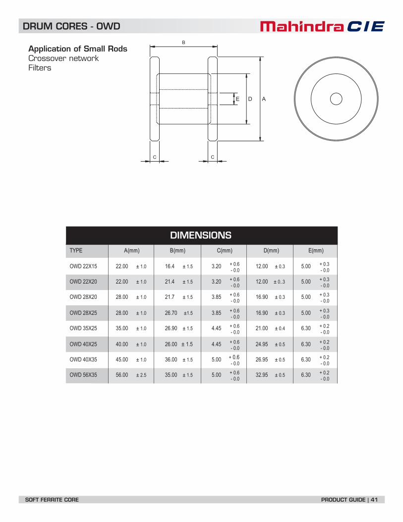
DRUM CORES - OWD
Application of Small RodsCrossover networkFilters
B
ADE
C C
TYPE A(mm) B(mm) C(mm) D(mm) E(mm)
3.0 +6.0 +OWD 22X15 22.00 ± 1.0 16.4 ± 1.5 3.20 12.00 ± 0.3 5.000.0 -0.0 -
3.0 +6.0 +OWD 22X20 22.00 ± 1.0 21.4 ± 1.5 3.20 12.00 ± 0..3 5.000.0 -0.0 -
3.0 +6.0 +OWD 28X20 28.00 ± 1.0 21.7 ± 1.5 3.85 16.90 ± 0.3 5.000.0 -0.0 -
3.0 +6.0 +OWD 28X25 28.00 ± 1.0 26.70 ±1.5 3.85 16.90 ± 0.3 5.000.0 -0.0 -
2.0 +6.0 +OWD 35X25 35.00 ± 1.0 26.90 ± 1.5 4.45 21.00 ± 0.4 6.300.0 -0.0 -
2.0 +6.0 +OWD 40X25 40.00 ± 1.0 26.00 ± 1.5 4.45 24.95 ± 0.5 6.300.0 -0.0 -
+ 0.6 + 0.2OWD 40X35 45.00 ± 1.0 36.00 ± 1.5 5.00 26.95 ± 0.5 6.300.0 -0.0 -
2.0 +6.0 +OWD 56X35 56.00 ± 2.5 35.00 ± 1.5 5.00 32.95 ± 0.5 6.300.0 -0.0 -
DIMENSIONS
TYPE A(mm) B(mm) (mm) Le Ae Ve AL AL Approx wt.
SOFT FERRITE CORE PRODUCT GUIDE | 41
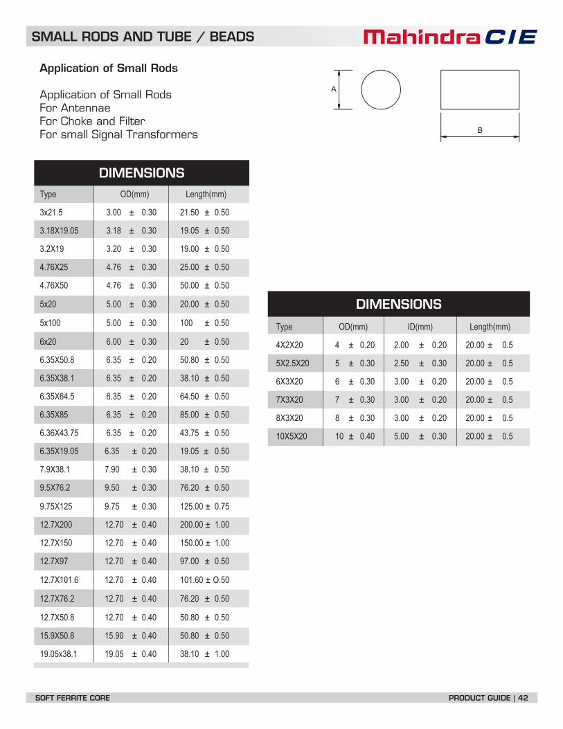
SMALL RODS AND TUBE / BEADS
Application of Small Rods
Application of Small RodsFor AntennaeFor Choke and FilterFor small Signal Transformers
Type OD(mm) ID(mm) Length(mm)
4X2X20 4 ± 0.20 2.00 ± 0.20 20.00 ± 0.5
5X2.5X20 5 ± 0.30 2.50 ± 0.30 20.00 ± 0.5
6X3X20 6 ± 0.30 3.00 ± 0.20 20.00 ± 0.5
7X3X20 7 ± 0.30 3.00 ± 0.20 20.00 ± 0.5
8X3X20 8 ± 0.30 3.00 ± 0.20 20.00 ± 0.5
10X5X20 10 ± 0.40 5.00 ± 0.30 20.00 ± 0.5
Type OD(mm) Length(mm)
3x21.5 3.00 ± 0.30 21.50 ± 0.50
3.18X19.05 3.18 ± 0.30 19.05 ± 0.50
3.2X19 3.20 ± 0.30 19.00 ± 0.50
4.76X25 4.76 ± 0.30 25.00 ± 0.50
4.76X50 4.76 ± 0.30 50.00 ± 0.50
5x20 5.00 ± 0.30 20.00 ± 0.50
5x100 5.00 ± 0.30 100 ± 0.50
6x20 6.00 ± 0.30 20 ± 0.50
6.35X50.8 6.35 ± 0.20 50.80 ± 0.50
6.35X38.1 6.35 ± 0.20 38.10 ± 0.50
6.35X64.5 6.35 ± 0.20 64.50 ± 0.50
6.35X85 6.35 ± 0.20 85.00 ± 0.50
6.36X43.75 6.35 ± 0.20 43.75 ± 0.50
6.35X19.05 6.35 ± 0.20 19.05 ± 0.50
7.9X38.1 7.90 ± 0.30 38.10 ± 0.50
9.5X76.2 9.50 ± 0.30 76.20 ± 0.50
9.75X125 9.75 ± 0.30 125.00 ± 0.75
12.7X200 12.70 ± 0.40 200.00 ± 1.00
12.7X150 12.70 ± 0.40 150.00 ± 1.00
12.7X97 12.70 ± 0.40 97.00 ± 0.50
12.7X101.6 12.70 ± 0.40 101.60 ± O.50
12.7X76.2 12.70 ± 0.40 76.20 ± 0.50
12.7X50.8 12.70 ± 0.40 50.80 ± 0.50
15.9X50.8 15.90 ± 0.40 50.80 ± 0.50
19.05x38.1 19.05 ± 0.40 38.10 ± 1.00
A
B
DIMENSIONS
DIMENSIONS
SOFT FERRITE CORE PRODUCT GUIDE | 42

Mahindra CIE Automotive Limited
Magnetic Product Division (MPD)
Bhosari Industrial Estate, Pune - 411026, INDIA.
Telephone - 020 - 66120400 • Fax - 020 - 27128592
email: [email protected]
Website - www.mahindracie.com
SOFT FERRITE CORE PRODUCT GUIDE | 43