Soffit formwork with H 20 timber beams Instructions for ... · PDF fileSoffit formwork with H...
24
Soffit formwork with H 20 timber beams Instructions for erection and use December 2004
Transcript of Soffit formwork with H 20 timber beams Instructions for ... · PDF fileSoffit formwork with H...
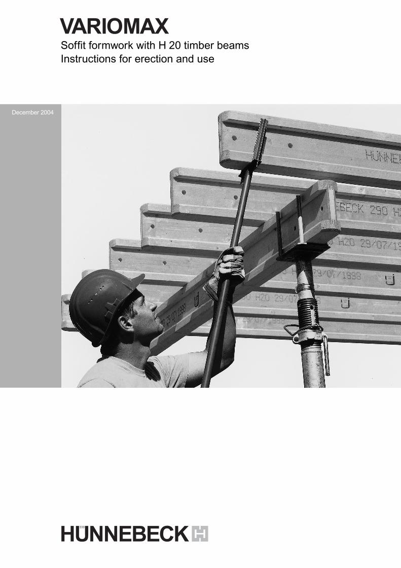
Soffit formwork with H 20 timber beamsInstructions for erection and use
December 2004
1-1182.Aufbauanl.VariomaxD+GB 08.12.2004 10:57 Uhr Seite 4
2
Table of contents
Important notes:The following instructions forerection and useinclude detailed informationon the handling andproper application of theproducts that are describedand depicted.All instructions regardingtechnical operation andfunction have to be observedcarefully. Exceptional userequires a separate designcalculation.With regard to safe andtechnically correct use ofour products abroad, allrelevant safety rules,regulations and safetyinstructions of nationalinstitutes and/or localauthorities have to befollowed.Generally, only flawlessmaterial must be used.
Damaged components haveto be sorted out. In case
1.0 Product featuresIn combination with tubularsteel props, tripod stands,fork heads and shutteringpanels, the H 20 beamsprovide flexible, yet cost-effective soffit formwork forany ground-plan , slabthickness and room height.
The H 20 timber beam isespecially practical due to itslow weight ( 5.0 kg/m ), itsgood statical figures, and itsexacting workmanship indetails.A very long duration of life isassured by its high-gradebonding and its roundedbeam ends.The H 20 timber has ageneral approval by thebuilding supervisory board.
of repairs, only original spareparts of the HÜNNEBECKCompany must be used.Combined use of ourformwork system withequipment from othersuppliers may involve certaindangers and, therefore,requires an additionalcheckup.
For reasons of furthertechnical development weemphatically reserve the rightto revise, change ormodify any of the product'scomponents at any timewithout prior notice.
1.0 Product features 22.0 Overview 33.0 Components 4–74.0 Use and erection 8–175.0 Stripping 186.0 Stripping and transport aids 197.0 Tables for shuttering panels 208.0 Load tables for H20 219.0 H20 shuttering example 22
10.0 Load tables for props 23
3
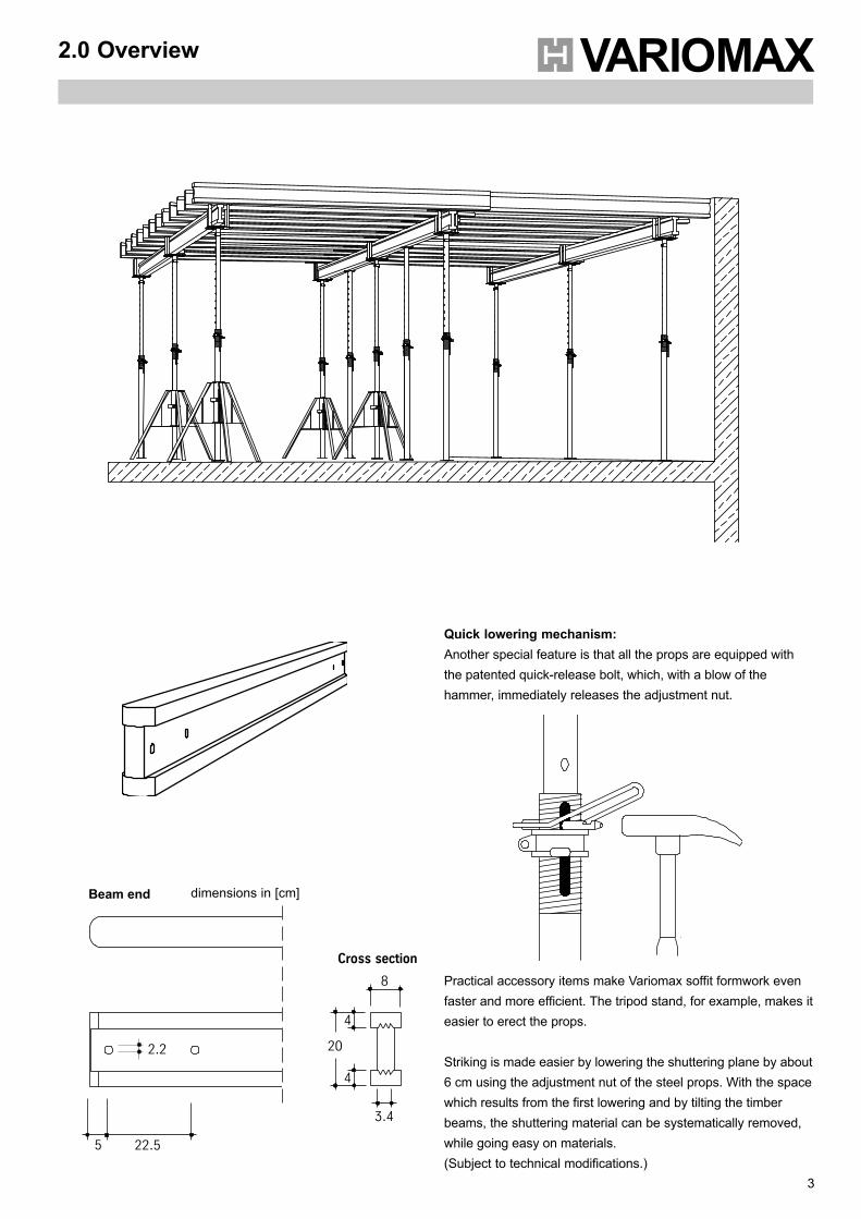
2.0 Overview
Quick lowering mechanism:Another special feature is that all the props are equipped withthe patented quick-release bolt, which, with a blow of thehammer, immediately releases the adjustment nut.
Practical accessory items make Variomax soffit formwork evenfaster and more efficient. The tripod stand, for example, makes iteasier to erect the props.
Striking is made easier by lowering the shuttering plane by about6 cm using the adjustment nut of the steel props. With the spacewhich results from the first lowering and by tilting the timberbeams, the shuttering material can be systematically removed,while going easy on materials.(Subject to technical modifications.)
Beam end
8
Cross section
3.4
4
2.2 20
4
22.55
dimensions in [cm]
Description Art. No Weightkg/pcs.
4
3.0 Components
8
max
. 5.
50 m
2.79
- 5
.00
m
12
1.4 dia
8
17
14
14
1.4 dia1.0 dia
8
20
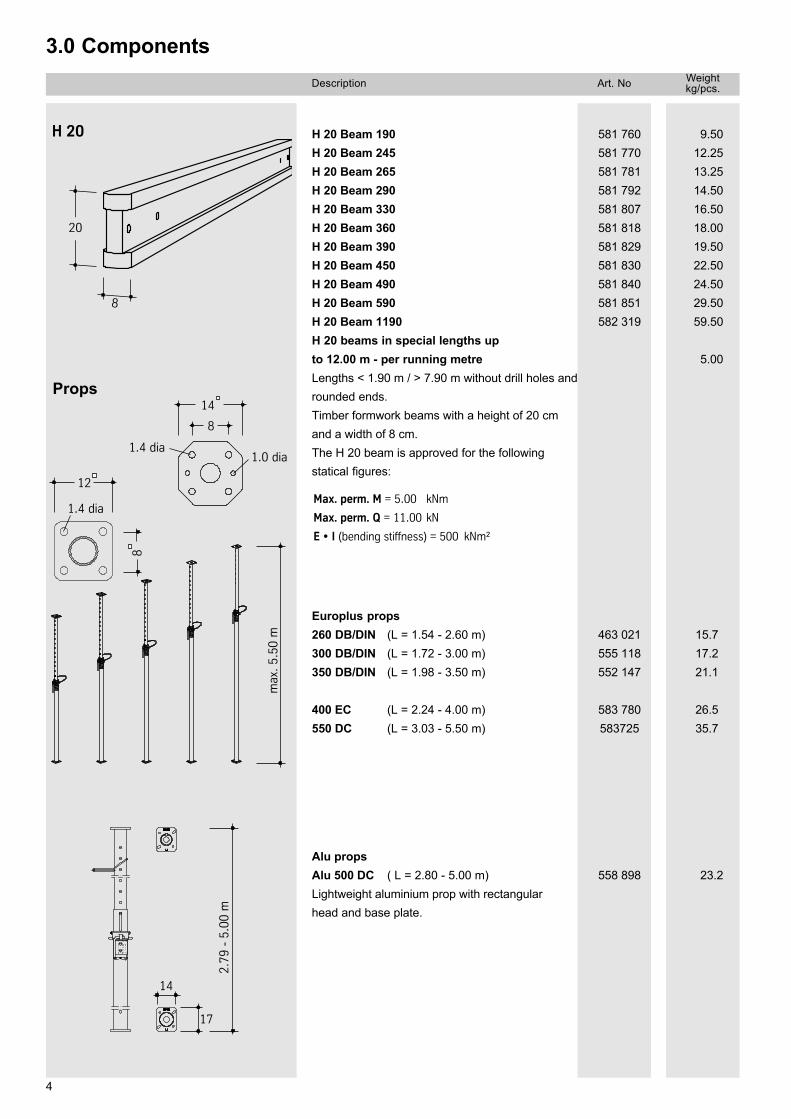
H 20
Props
9.5012.2513.2514.5016.5018.0019.5022.5024.5029.50 59.50
5.00
581 760581 770581 781581 792581 807581 818581 829581 830581 840581 851582 319
H 20 Beam 190H 20 Beam 245H 20 Beam 265H 20 Beam 290H 20 Beam 330H 20 Beam 360H 20 Beam 390H 20 Beam 450H 20 Beam 490H 20 Beam 590H 20 Beam 1190H 20 beams in special lengths upto 12.00 m - per running metreLengths < 1.90 m / > 7.90 m without drill holes androunded ends.Timber formwork beams with a height of 20 cmand a width of 8 cm.The H 20 beam is approved for the followingstatical figures:
Max. perm. M = 5.00 kNm
Max. perm. Q = 11.00 kN
E • I (bending stiffness) = 500 kNm²
15.717.221.1
26.535.7
463 021555 118552 147
583 780583725
Europlus props260 DB/DIN (L = 1.54 - 2.60 m)300 DB/DIN (L = 1.72 - 3.00 m)350 DB/DIN (L = 1.98 - 3.50 m)
400 EC (L = 2.24 - 4.00 m)550 DC (L = 3.03 - 5.50 m)
23.2558 898Alu propsAlu 500 DC ( L = 2.80 - 5.00 m)Lightweight aluminium prop with rectangularhead and base plate.
5
Description Art. No Weightkg/pcs.
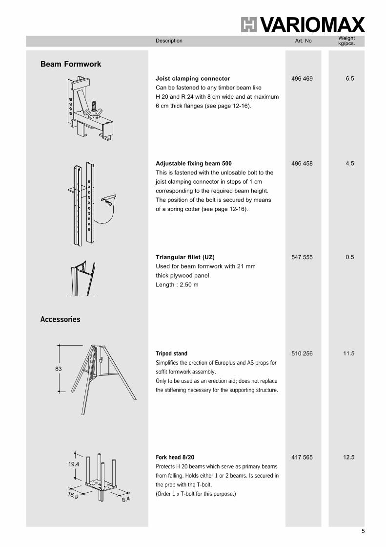
Joist clamping connectorCan be fastened to any timber beam likeH 20 and R 24 with 8 cm wide and at maximum6 cm thick flanges (see page 12-16).
496 469 6.5
Adjustable fixing beam 500This is fastened with the unlosable bolt to thejoist clamping connector in steps of 1 cmcorresponding to the required beam height.The position of the bolt is secured by meansof a spring cotter (see page 12-16).
496 458 4.5
16.98.4
83
19.4
Triangular fillet (UZ)Used for beam formwork with 21 mmthick plywood panel.Length : 2.50 m
547 555 0.5
Beam Formwork
Accessories
Tripod stand
Simplifies the erection of Europlus and AS props for
soffit formwork assembly.
Only to be used as an erection aid; does not replace
the stiffening necessary for the supporting structure.
510 256 11.5
Fork head 8/20
Protects H 20 beams which serve as primary beams
from falling. Holds either 1 or 2 beams. Is secured in
the prop with the T-bolt.
(Order 1 x T-bolt for this purpose.)
417 565 12.5
Description Art. No Weightkg/pcs.
6
3.0 Components
8
5.8
9.4
1.5 Ø
1.2 Ø
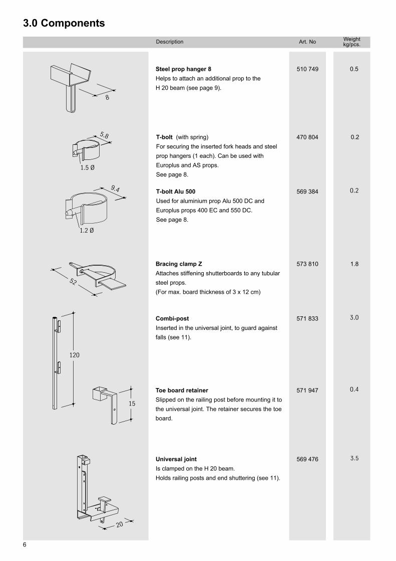
Steel prop hanger 8Helps to attach an additional prop to theH 20 beam (see page 9).
510 749 0.5
T-bolt (with spring)For securing the inserted fork heads and steelprop hangers (1 each). Can be used withEuroplus and AS props.See page 8.
470 804 0.2
T-bolt Alu 500Used for aluminium prop Alu 500 DC andEuroplus props 400 EC and 550 DC.See page 8.
569 384 0.2
52
Bracing clamp ZAttaches stiffening shutterboards to any tubularsteel props.(For max. board thickness of 3 x 12 cm)
573 810 1.8
20
Universal jointIs clamped on the H 20 beam.Holds railing posts and end shuttering (see 11).
569 476 3.5
120
Combi-postInserted in the universal joint, to guard againstfalls (see 11).
571 833 3.0
Toe board retainerSlipped on the railing post before mounting it tothe universal joint. The retainer secures the toeboard.
571 947 0.4
15
7
Description Art. No Weightkg/pcs.
80
80
120
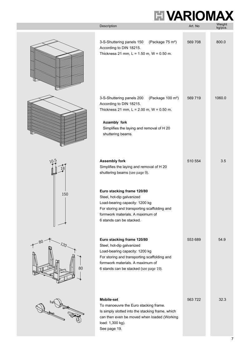
3-S-Shuttering panels 150 (Package 75 m²)According to DIN 18215.Thickness 21 mm, L = 1.50 m, W = 0.50 m.
569 708 800.0
3-S-Shuttering panels 200 (Package 100 m²)According to DIN 18215.Thickness 21 mm, L = 2.00 m, W = 0.50 m.
569 719 1060.0
10.5
18
150
Assembly forkSimplifies the laying and removal of H 20shuttering beams (see page 9).
510 554 3.5
Euro stacking frame 120/80Steel, hot-dip galvanizedLoad-bearing capacity: 1200 kgFor storing and transporting scaffolding andformwork materials. A maximum of6 stands can be stacked (see page 19).
553 689 54.9
Mobile-setTo manoeuvre the Euro stacking frame.Is simply slotted into the stacking frame, whichcan then even be moved when loaded (Workingload: 1,300 kg).See page 19.
563 722 32.3
Assembly fork
Simplifies the laying and removal of H 20shuttering beams.
Euro stacking frame 120/80Steel, hot-dip galvanizedLoad-bearing capacity: 1200 kgFor storing and transporting scaffolding andformwork materials. A maximum of6 stands can be stacked.
8
4.0 Use and erection
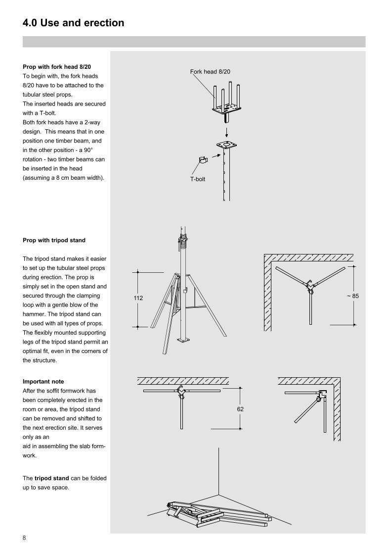
Fork head 8/20
T-bolt
Prop with tripod stand
The tripod stand makes it easierto set up the tubular steel propsduring erection. The prop issimply set in the open stand andsecured through the clampingloop with a gentle blow of thehammer. The tripod stand canbe used with all types of props.The flexibly mounted supportinglegs of the tripod stand permit anoptimal fit, even in the corners ofthe structure.
Important noteAfter the soffit formwork hasbeen completely erected in theroom or area, the tripod standcan be removed and shifted tothe next erection site. It servesonly as anaid in assembling the slab form-work.
The tripod stand can be foldedup to save space.
112 ~ 85
62
Prop with fork head 8/20To begin with, the fork heads8/20 have to be attached to thetubular steel props.The inserted heads are securedwith a T-bolt.Both fork heads have a 2-waydesign. This means that in oneposition one timber beam, andin the other position - a 90°rotation - two timber beams canbe inserted in the head(assuming a 8 cm beam width).
9
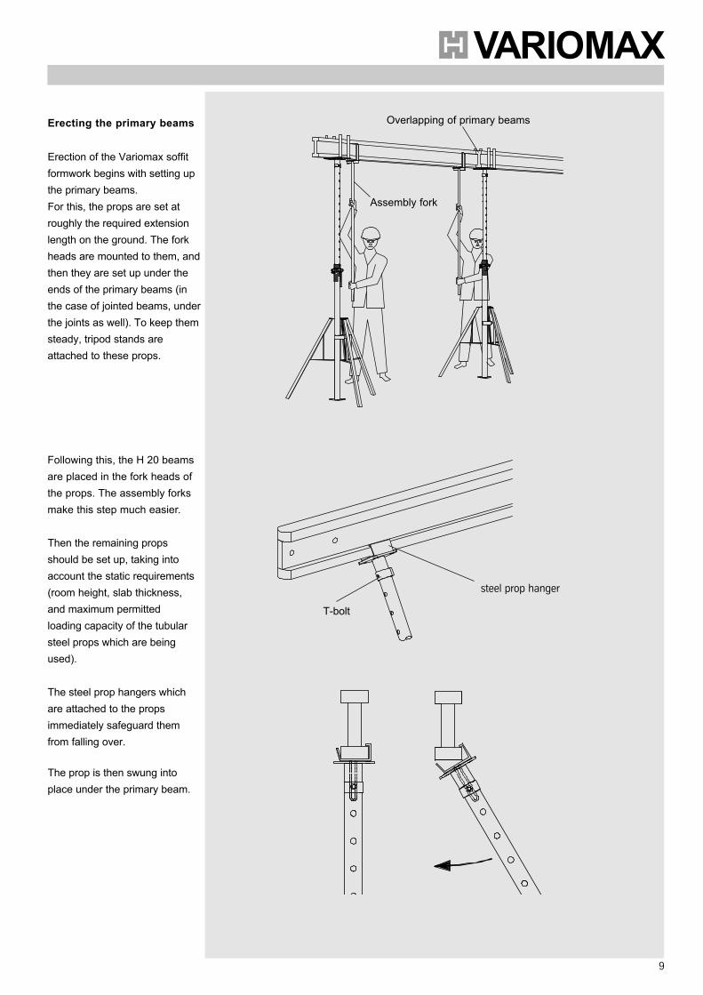
Erecting the primary beams
Erection of the Variomax soffitformwork begins with setting upthe primary beams.For this, the props are set atroughly the required extensionlength on the ground. The forkheads are mounted to them, andthen they are set up under theends of the primary beams (inthe case of jointed beams, underthe joints as well). To keep themsteady, tripod stands areattached to these props.
Following this, the H 20 beamsare placed in the fork heads ofthe props. The assembly forksmake this step much easier.
Then the remaining propsshould be set up, taking intoaccount the static requirements(room height, slab thickness,and maximum permittedloading capacity of the tubularsteel props which are beingused).
The steel prop hangers whichare attached to the propsimmediately safeguard themfrom falling over.
The prop is then swung intoplace under the primary beam.
Assembly fork
Overlapping of primary beams
steel prop hanger
T-bolt
10
4.0 Use and erection
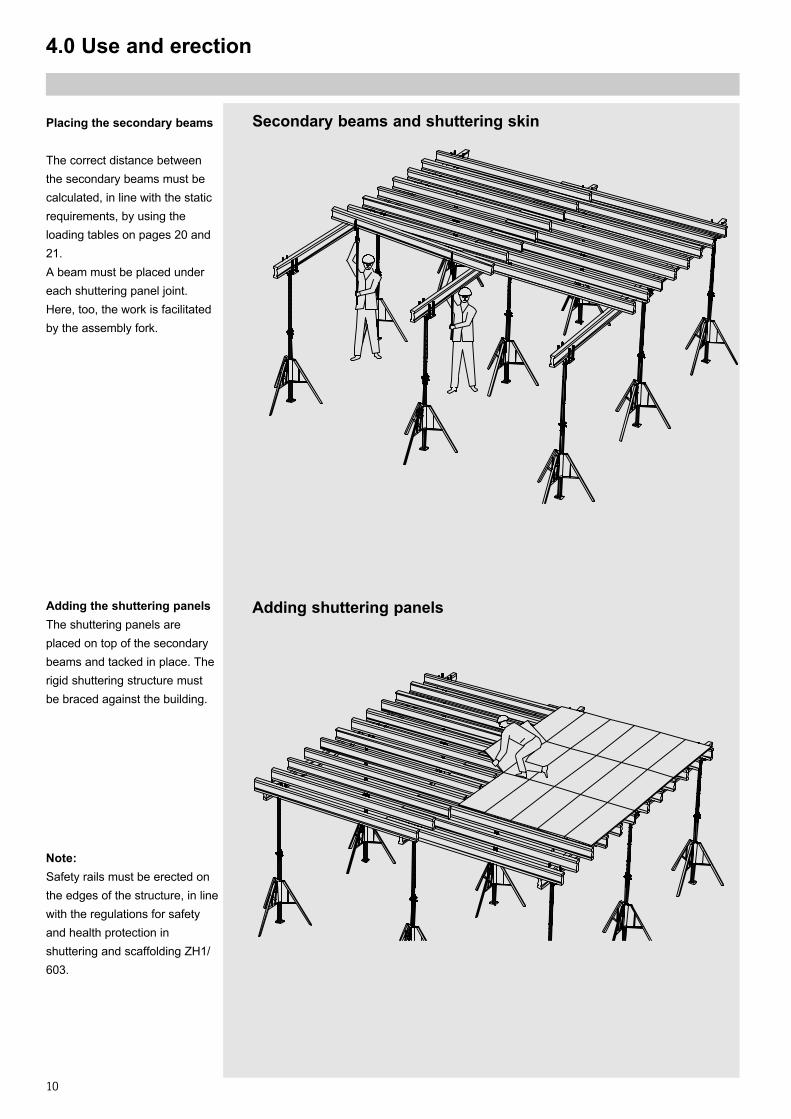
Secondary beams and shuttering skin
Adding the shuttering panelsThe shuttering panels areplaced on top of the secondarybeams and tacked in place. Therigid shuttering structure mustbe braced against the building.
Placing the secondary beams
The correct distance betweenthe secondary beams must becalculated, in line with the staticrequirements, by using theloading tables on pages 20 and21.A beam must be placed undereach shuttering panel joint.Here, too, the work is facilitatedby the assembly fork.
Note:Safety rails must be erected onthe edges of the structure, in linewith the regulations for safetyand health protection inshuttering and scaffolding ZH1/603.
Adding shuttering panels
11
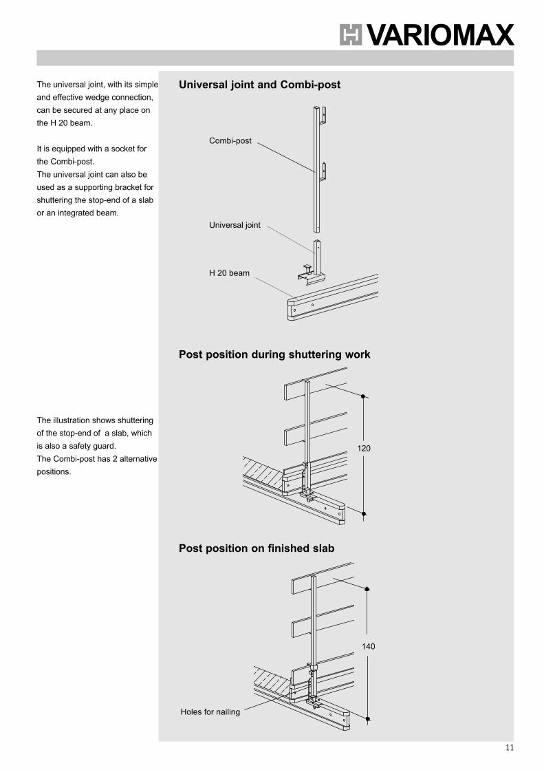
The universal joint, with its simpleand effective wedge connection,can be secured at any place onthe H 20 beam.
It is equipped with a socket forthe Combi-post.The universal joint can also beused as a supporting bracket forshuttering the stop-end of a slabor an integrated beam.
Post position during shuttering work
Post position on finished slab
Holes for nailing
The illustration shows shutteringof the stop-end of a slab, whichis also a safety guard.The Combi-post has 2 alternativepositions.
H 20 beam
Universal joint
Combi-post
120
140
Universal joint and Combi-post
12
4.0 Use and erection
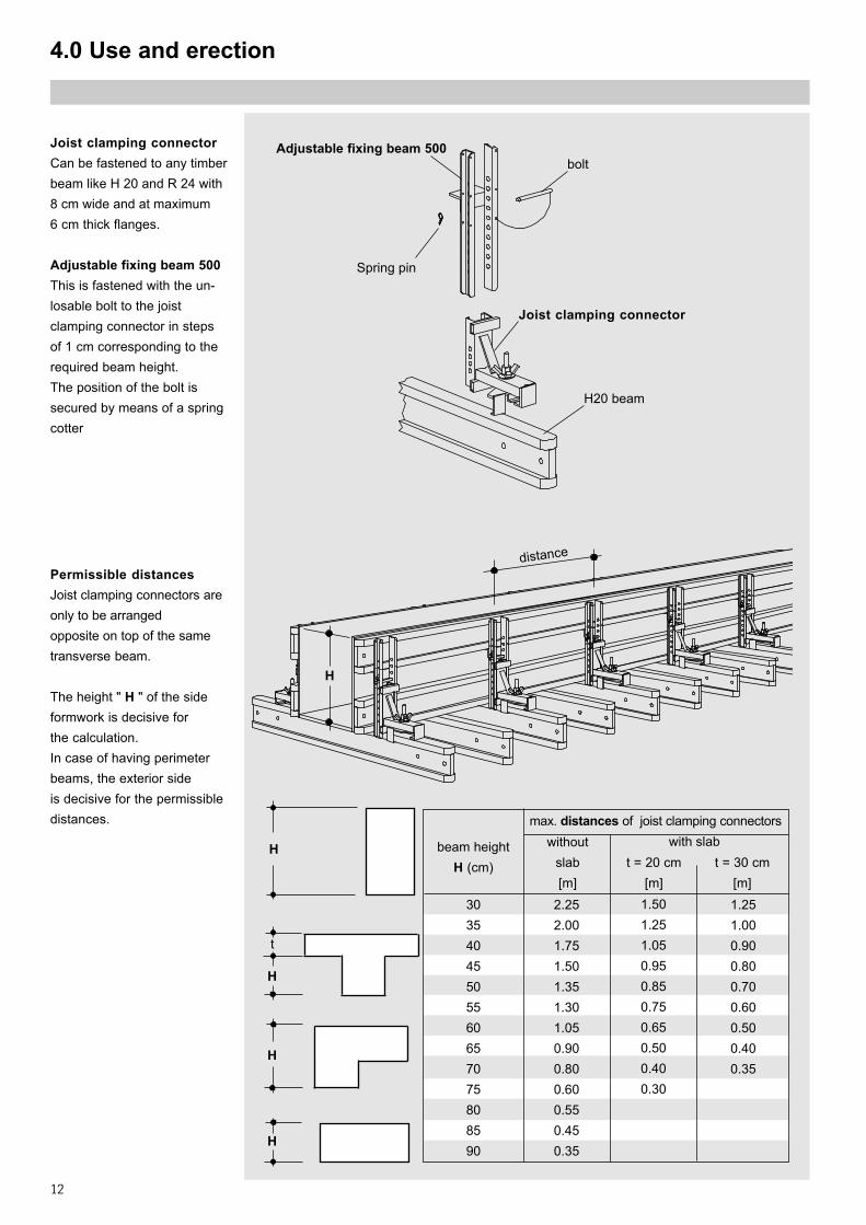
Adjustable fixing beam 500
Joist clamping connector
H20 beam
Joist clamping connectorCan be fastened to any timberbeam like H 20 and R 24 with8 cm wide and at maximum6 cm thick flanges.
Adjustable fixing beam 500This is fastened with the un-losable bolt to the joistclamping connector in stepsof 1 cm corresponding to therequired beam height.The position of the bolt issecured by means of a springcotter
Spring pin
bolt
Permissible distancesJoist clamping connectors areonly to be arrangedopposite on top of the sametransverse beam.
The height " H " of the sideformwork is decisive forthe calculation.In case of having perimeterbeams, the exterior sideis decisive for the permissibledistances.
distance
H
beam heightH (cm)
withoutslab[m]
t = 20 cm[m]
t = 30 cm[m]
30354045505560657075808590
2.252.001.751.501.351.301.050.900.800.600.550.450.35
1.501.251.050.950.850.750.650.500.400.30
1.251.000.900.800.700.600.500.400.35
H
H
t
H
H
max. distances of joist clamping connectorswith slab
13
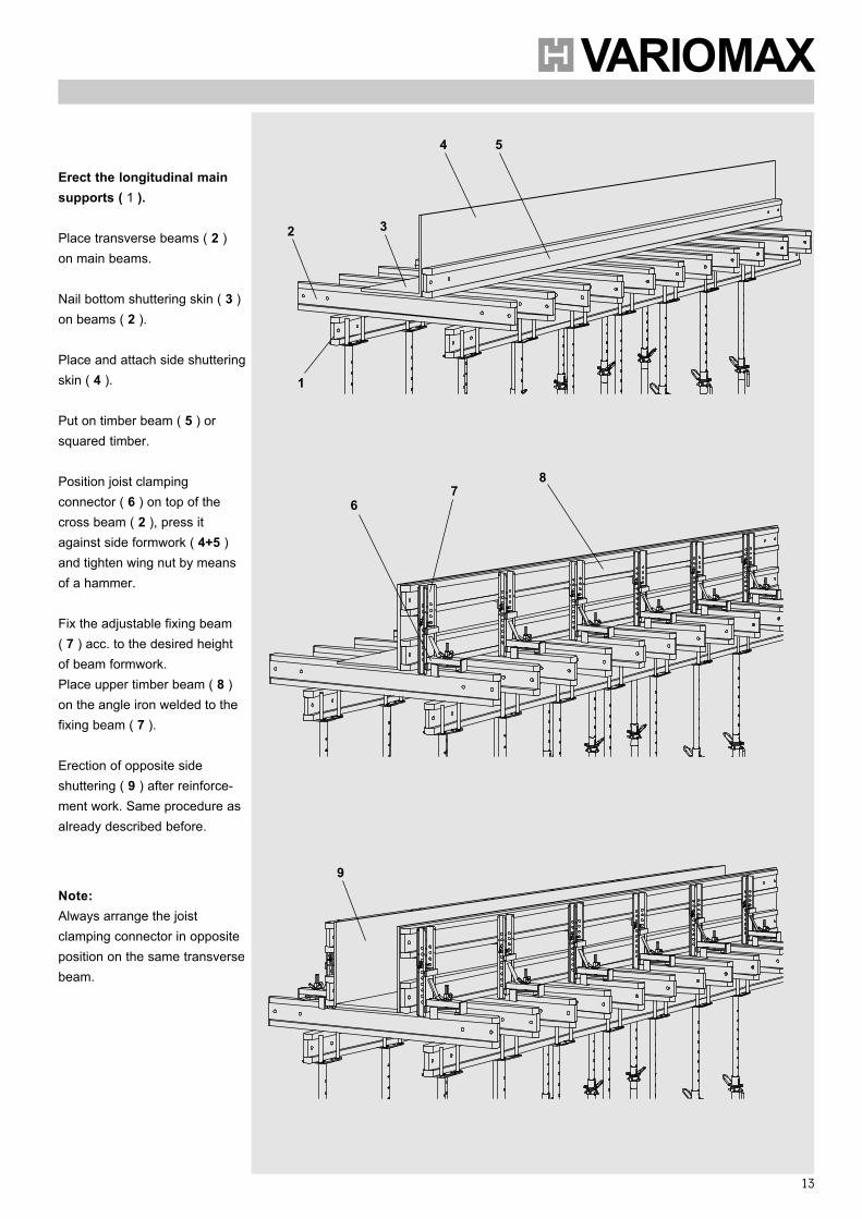
Erect the longitudinal mainsupports ( 1 ).
Place transverse beams ( 2 )on main beams.
Nail bottom shuttering skin ( 3 )on beams ( 2 ).
Place and attach side shutteringskin ( 4 ).
Put on timber beam ( 5 ) orsquared timber.
Position joist clampingconnector ( 6 ) on top of thecross beam ( 2 ), press itagainst side formwork ( 4+5 )and tighten wing nut by meansof a hammer.
Fix the adjustable fixing beam( 7 ) acc. to the desired heightof beam formwork.Place upper timber beam ( 8 )on the angle iron welded to thefixing beam ( 7 ).
Erection of opposite sideshuttering ( 9 ) after reinforce-ment work. Same procedure asalready described before.
Note:Always arrange the joistclamping connector in oppositeposition on the same transversebeam.
2 3
4 5
1
67
8
9
14
4.0 Use and erection
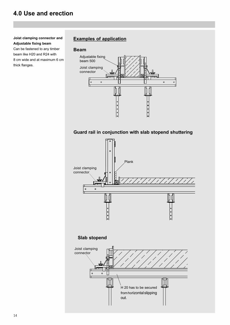
Beam
Joist clamping connector andAdjustable fixing beamCan be fastened to any timberbeam like H20 and R24 with8 cm wide and at maximum 6 cmthick flanges.
Joist clampingconnector
Adjustable fixingbeam 500
Joist clampingconnector
Examples of application
Slab stopend
H 20 has to be securedfrom horizontal slippingout.
Joist clampingconnector
Plank
11111
Guard rail in conjunction with slab stopend shuttering
15
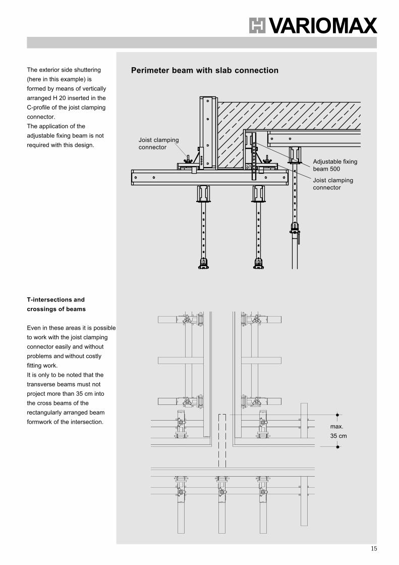
Perimeter beam with slab connection
Joist clampingconnector
Adjustable fixingbeam 500
Joist clampingconnector
T-intersections andcrossings of beams
Even in these areas it is possibleto work with the joist clampingconnector easily and withoutproblems and without costlyfitting work.It is only to be noted that thetransverse beams must notproject more than 35 cm intothe cross beams of therectangularly arranged beamformwork of the intersection.
The exterior side shuttering(here in this example) isformed by means of verticallyarranged H 20 inserted in theC-profile of the joist clampingconnector.The application of theadjustable fixing beam is notrequired with this design.
max.35 cm
16
4.0 Use and erection
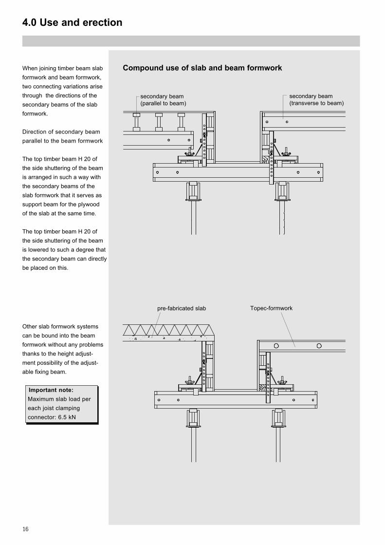
When joining timber beam slabformwork and beam formwork,two connecting variations arisethrough the directions of thesecondary beams of the slabformwork.
Direction of secondary beamparallel to the beam formwork
The top timber beam H 20 ofthe side shuttering of the beamis arranged in such a way withthe secondary beams of theslab formwork that it serves assupport beam for the plywoodof the slab at the same time.
The top timber beam H 20 ofthe side shuttering of the beamis lowered to such a degree thatthe secondary beam can directlybe placed on this.
Compound use of slab and beam formwork
Other slab formwork systemscan be bound into the beamformwork without any problemsthanks to the height adjust-ment possibility of the adjust-able fixing beam.
Important note:Maximum slab load pereach joist clampingconnector: 6.5 kN
secondary beam(transverse to beam)
secondary beam(parallel to beam)
pre-fabricated slab Topec-formwork
17
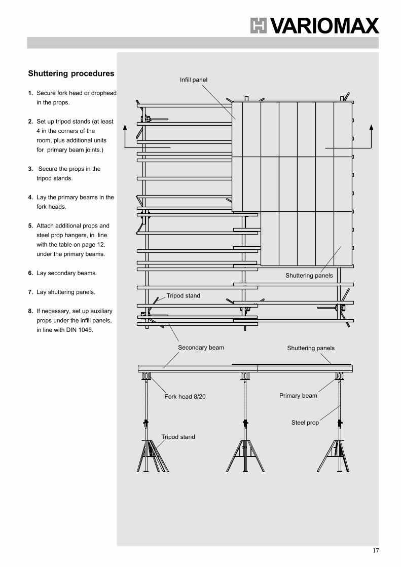
Shuttering procedures
1. Secure fork head or dropheadin the props.
2. Set up tripod stands (at least4 in the corners of theroom, plus additional unitsfor primary beam joints.)
3. Secure the props in thetripod stands.
4. Lay the primary beams in thefork heads.
5. Attach additional props andsteel prop hangers, in linewith the table on page 12,under the primary beams.
6. Lay secondary beams.
7. Lay shuttering panels.
8. If necessary, set up auxiliaryprops under the infill panels,in line with DIN 1045.
Primary beamFork head 8/20
Tripod stand
Shuttering panels
Steel prop
Infill panel
Tripod stand
Secondary beam Shuttering panels
18
5.0 Stripping
Stripping procedures with fork heads 8/20:
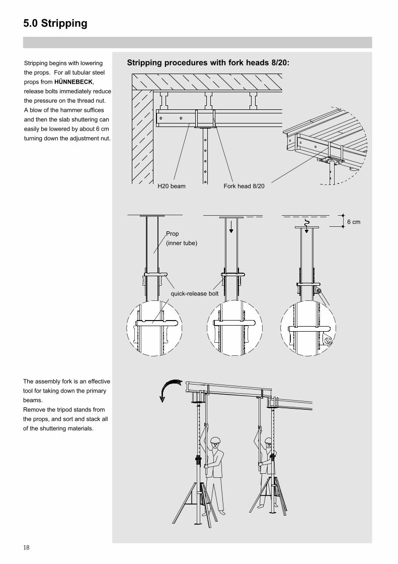
The assembly fork is an effectivetool for taking down the primarybeams.Remove the tripod stands fromthe props, and sort and stack allof the shuttering materials.
Fork head 8/20H20 beam
Stripping begins with loweringthe props. For all tubular steelprops from HÜNNEBECK,release bolts immediately reducethe pressure on the thread nut.A blow of the hammer sufficesand then the slab shuttering caneasily be lowered by about 6 cmturning down the adjustment nut.
quick-release bolt
6 cm
Prop(inner tube)
19
6.0 Stripping and transport aids
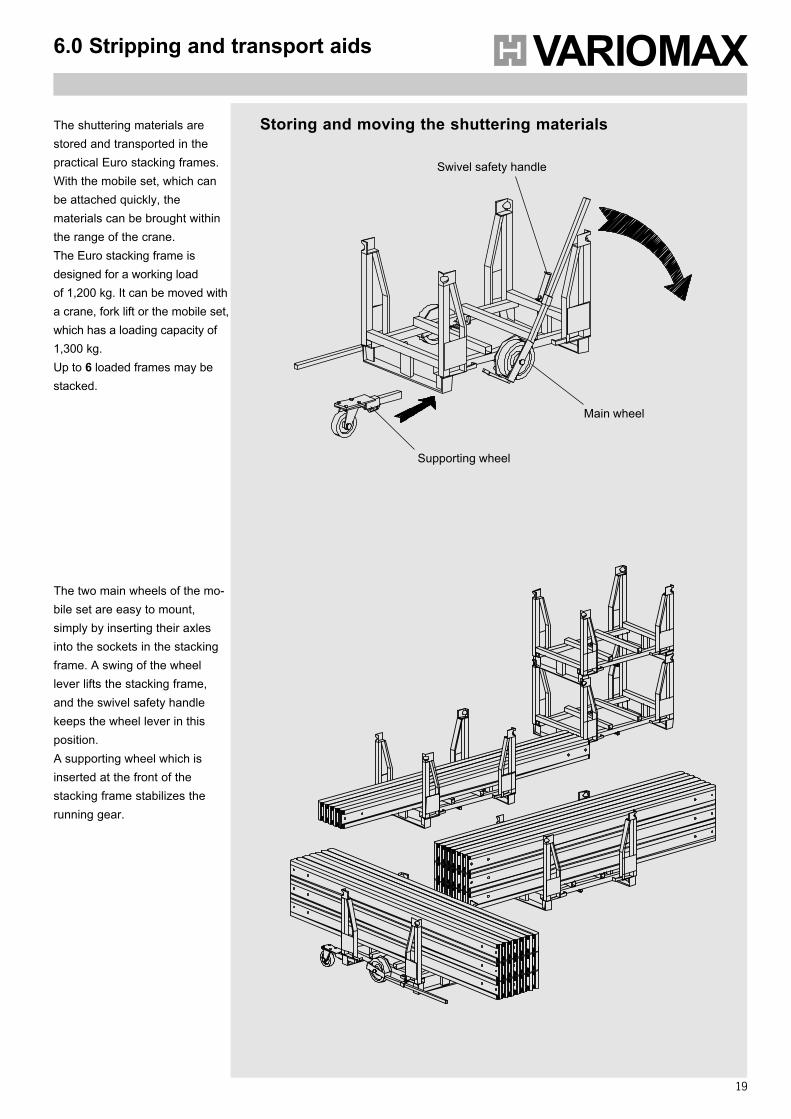
The shuttering materials arestored and transported in thepractical Euro stacking frames.With the mobile set, which canbe attached quickly, thematerials can be brought withinthe range of the crane.The Euro stacking frame isdesigned for a working loadof 1,200 kg. It can be moved witha crane, fork lift or the mobile set,which has a loading capacity of1,300 kg.Up to 6 loaded frames may bestacked.
Supporting wheel
Swivel safety handle
Main wheel
The two main wheels of the mo-bile set are easy to mount,simply by inserting their axlesinto the sockets in the stackingframe. A swing of the wheellever lifts the stacking frame,and the swivel safety handlekeeps the wheel lever in thisposition.A supporting wheel which isinserted at the front of thestacking frame stabilizes therunning gear.
Storing and moving the shuttering materials
20
7.0 Tables for shuttering panels
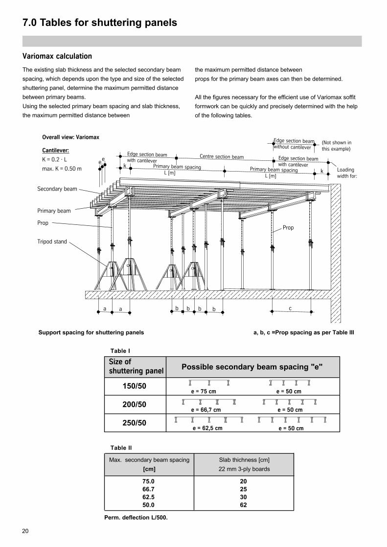
Variomax calculation
The existing slab thickness and the selected secondary beamspacing, which depends upon the type and size of the selectedshuttering panel, determine the maximum permitted distancebetween primary beams.Using the selected primary beam spacing and slab thickness,the maximum permitted distance between
the maximum permitted distance betweenprops for the primary beam axes can then be determined.
All the figures necessary for the efficient use of Variomax soffitformwork can be quickly and precisely determined with the helpof the following tables.
Loadingwidth for:
(Not shown inthis example)
ee
b b ba
Secondary beam
a b
Overall view: Variomax
Cantilever:
K = 0.2 · L
max. K = 0.50 m k
Prop
c
Primary beam
Prop
Tripod stand
Support spacing for shuttering panels
e = 66,7 cm e = 50 cm
e = 75 cm e = 50 cm
Possible secondary beam spacing "e"
e = 50 cme = 62,5 cm
200/50
150/50
250/50
Size ofshuttering panel
Table I
a, b, c =Prop spacing as per Table III
k
Perm. deflection L/500.
Table II
Max. secondary beam spacing[cm]
75.066.762.550.0
Slab thichness [cm]22 mm 3-ply boards
20253062
Edge section beamwithout cantilever
Primary beam spacing Primary beam spacing L [m] L [m]
Edge section beamwith cantilever
Edge section beamwith cantilever
Centre section beam
21
8.0 Load tables for H20
20
K K
c) or centre section beamL/2
L/2
L/2
L/2
L L
K
b) or edge section beam
with cantilever in „m“
L/2
L/2 ( max. K = 0.50 m)
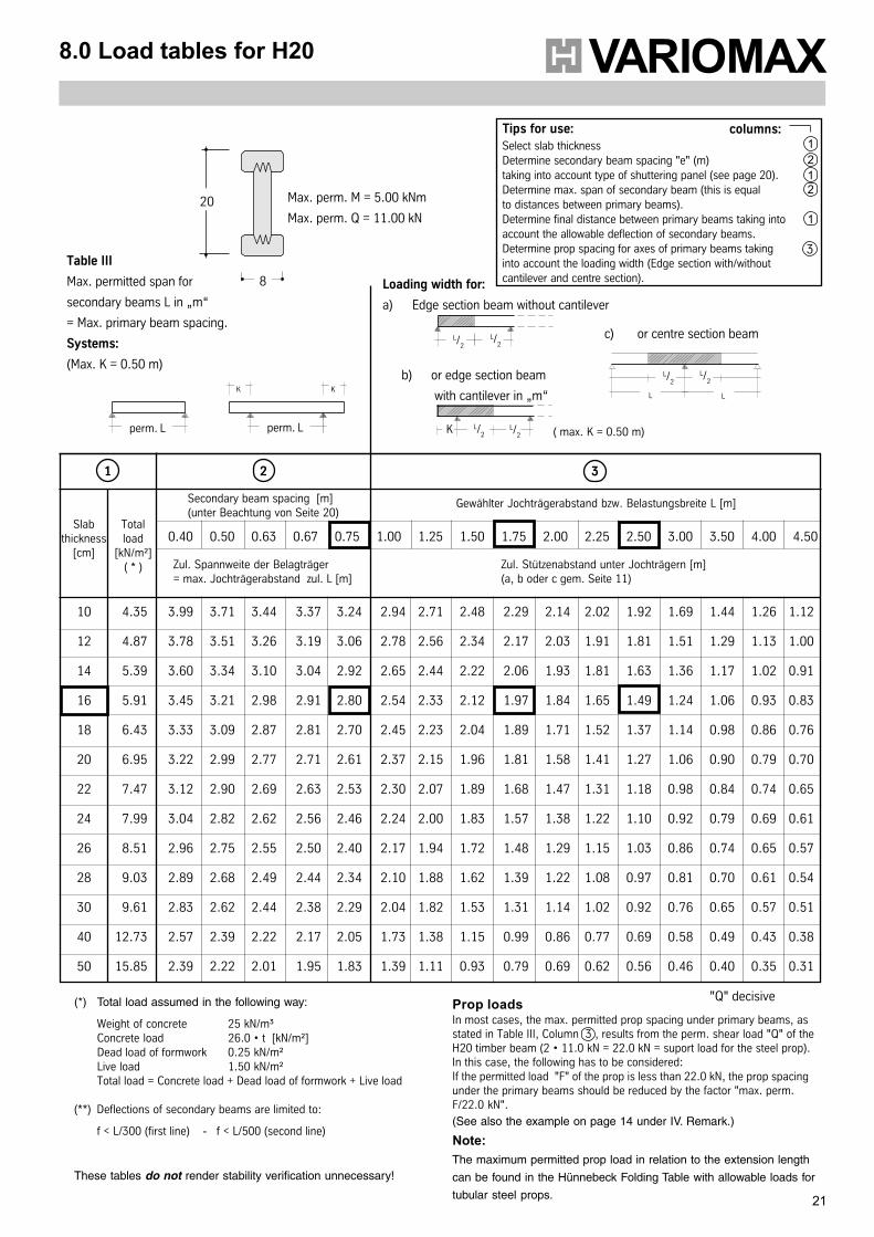
Table III
Max. permitted span for
secondary beams L in „m“
= Max. primary beam spacing.
Systems:
(Max. K = 0.50 m)
Prop loadsIn most cases, the max. permitted prop spacing under primary beams, asstated in Table III, Column 3 , results from the perm. shear load "Q" of theH20 timber beam (2 • 11.0 kN = 22.0 kN = suport load for the steel prop).In this case, the following has to be considered:If the permitted load "F" of the prop is less than 22.0 kN, the prop spacingunder the primary beams should be reduced by the factor "max. perm.F/22.0 kN".
(See also the example on page 14 under IV. Remark.)
Note:The maximum permitted prop load in relation to the extension length
can be found in the Hünnebeck Folding Table with allowable loads for
tubular steel props.
Loading width for:
a) Edge section beam without cantilever
Tips for use:Select slab thicknessDetermine secondary beam spacing "e" (m)taking into account type of shuttering panel (see page 20).Determine max. span of secondary beam (this is equalto distances between primary beams).Determine final distance between primary beams taking intoaccount the allowable deflection of secondary beams.Determine prop spacing for axes of primary beams takinginto account the loading width (Edge section with/withoutcantilever and centre section).
3
2
These tables do not render stability verification unnecessary!
"Q" decisive(*) Total load assumed in the following way:
Weight of concrete 25 kN/m³Concrete load 26.0 • t [kN/m²]Dead load of formwork 0.25 kN/m²Live load 1.50 kN/m²Total load = Concrete load + Dead load of formwork + Live load
(**) Deflections of secondary beams are limited to:
f < L/300 (first line) - f < L/500 (second line)
perm. L perm. L
columns:
8
Max. perm. M = 5.00 kNm
Max. perm. Q = 11.00 kN
3.99 3.71 3.44 3.37 3.24 2.94 2.71 2.48 2.29 2.14 2.02 1.92 1.69 1.44 1.26 1.12
3.78 3.51 3.26 3.19 3.06 2.78 2.56 2.34 2.17 2.03 1.91 1.81 1.51 1.29 1.13 1.00
3.60 3.34 3.10 3.04 2.92 2.65 2.44 2.22 2.06 1.93 1.81 1.63 1.36 1.17 1.02 0.91
3.45 3.21 2.98 2.91 2.80 2.54 2.33 2.12 1.97 1.84 1.65 1.49 1.24 1.06 0.93 0.83
3.33 3.09 2.87 2.81 2.70 2.45 2.23 2.04 1.89 1.71 1.52 1.37 1.14 0.98 0.86 0.76
3.22 2.99 2.77 2.71 2.61 2.37 2.15 1.96 1.81 1.58 1.41 1.27 1.06 0.90 0.79 0.70
3.12 2.90 2.69 2.63 2.53 2.30 2.07 1.89 1.68 1.47 1.31 1.18 0.98 0.84 0.74 0.65
3.04 2.82 2.62 2.56 2.46 2.24 2.00 1.83 1.57 1.38 1.22 1.10 0.92 0.79 0.69 0.61
2.96 2.75 2.55 2.50 2.40 2.17 1.94 1.72 1.48 1.29 1.15 1.03 0.86 0.74 0.65 0.57
2.89 2.68 2.49 2.44 2.34 2.10 1.88 1.62 1.39 1.22 1.08 0.97 0.81 0.70 0.61 0.54
2.83 2.62 2.44 2.38 2.29 2.04 1.82 1.53 1.31 1.14 1.02 0.92 0.76 0.65 0.57 0.51
2.57 2.39 2.22 2.17 2.05 1.73 1.38 1.15 0.99 0.86 0.77 0.69 0.58 0.49 0.43 0.38
2.39 2.22 2.01 1.95 1.83 1.39 1.11 0.93 0.79 0.69 0.62 0.56 0.46 0.40 0.35 0.31
Zul. Spannweite der Belagträger= max. Jochträgerabstand zul. L [m]
Zul. Stützenabstand unter Jochträgern [m](a, b oder c gem. Seite 11)
Slabthickness
[cm]
Totalload
[kN/m²]( * )
10 4.35
12 4.87
14 5.39
16 5.91
18 6.43
20 6.95
22 7.47
24 7.99
26 8.51
28 9.03
30 9.61
40 12.73
50 15.85
0.40 0.50 0.63 0.67 0.75 1.00 1.25 1.50 1.75 2.00 2.25 2.50 3.00 3.50 4.00 4.50
321
Secondary beam spacing [m](unter Beachtung von Seite 20)
Gewählter Jochträgerabstand bzw. Belastungsbreite L [m]
1
1
2
1
22
9.0 H20 Shuttering example
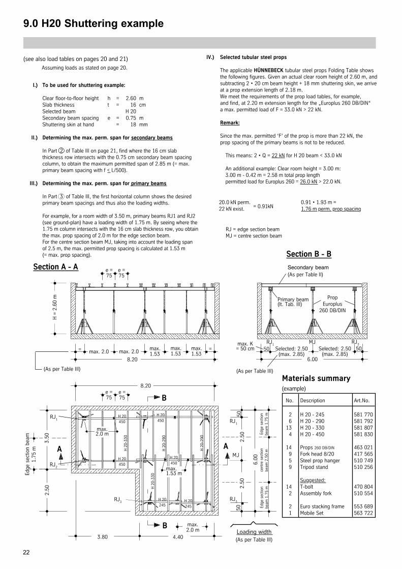
(see also load tables on pages 20 and 21) IV.) Selected tubular steel props
The applicable HÜNNEBECK tubular steel props Folding Table showsthe following figures. Given an actual clear room height of 2.60 m, andsubtracting 2 • 20 cm beam height + 18 mm shuttering skin, we arriveat a prop extension length of 2.18 m.We meet the requirements of the prop load tables, for example,and find, at 2.20 m extension length for the „Europlus 260 DB/DIN“a max. permitted load of F = 33.0 kN > 22 kN.
Remark:
Since the max. permitted ‘F’ of the prop is more than 22 kN, theprop spacing of the primary beams is not to be reduced.
This means: 2 • Q = 22 kN for H 20 beam < 33.0 kN
An additional example: Clear room height = 3.00 m:3.00 m - 0.42 m = 2.58 m total prop lengthpermitted load for Europlus 260 = 26.0 kN > 22.0 kN.
max. 2.0max.1.53
max.1.53
max.1.53
8.20
8.20e =75
3.80 4.40
max.2.0 m
2.50
3.50
2.50
2.50
6.00
50
RJ2
RJ1
MJ
RJ1
RJ3
Loading width(As per Table III)
B
A A
B
max.1.53 m
Selected: 2.50(max. 2.85)
6.00
Primary beam(lt. Tab. III)
RJ1
RJ3MJmax. K
= 50 cm
Materials summary(example)
RJ3
H =
2.6
0 m
Assuming loads as stated on page 20.
Section A - A
max. 2.0= Selected: 2.50(max. 2.85)
e =75
= 50 50
e =75
e =75
H 20450
H 20450
H 20450
H 20450
H 20245
H 20245
H 2
0-29
0
H 2
0-29
0
H 2
0-33
0
H 2
0-33
0
Section B - B
Secondary beam(As per Table II)
(As per Table III)(As per Table III)
Edge
sec
tion
beam
1.
75 m
Edge
sec
tion
beam
1.7
5 m
cent
re s
ectio
nbe
am 2
.50
mEd
ge s
ectio
nbe
am 1
.75
m
I.) To be used for shuttering example:
Clear floor-to-floor height h = 2.60 mSlab thickness t = 16 cmSelected beam H 20Secondary beam spacing e = 0.75 mShuttering skin at hand = 18 mm
II.) Determining the max. perm. span for secondary beams
In Part 2 of Table III on page 21, find where the 16 cm slabthickness row intersects with the 0.75 cm secondary beam spacingcolumn, to obtain the maximum permitted span of 2.85 m (= max.primary beam spacing with f < L/500).
III.) Determining the max. perm. span for primary beams
In Part 3 of Table III, the first horizontal column shows the desiredprimary beam spacings and thus also the loading widths.
For example, for a room width of 3.50 m, primary beams RJ1 and RJ2(see ground-plan) have a loading width of 1.75 m. By seeing where the1.75 m column intersects with the 16 cm slab thickness row, you obtainthe max. prop spacing of 2.0 m for the edge section beam.For the centre section beam MJ, taking into account the loading spanof 2.5 m, the max. permitted prop spacing is calculated at 1.53 m(= max. prop spacing).
max.2.0 m
50
No. Description Art.No.
2 H 20 - 245 581 7706 H 20 - 290 581 792
13 H 20 - 330 581 8074 H 20 - 450 581 830
14 Props 260 DB/DIN 463 0219 Fork head 8/20 417 5655 Steel prop hanger 510 7499 Tripod stand 510 256
Suggested:14 T-bolt 470 804
2 Assembly fork 510 554
2 Euro stacking frame 553 6891 Mobile Set 563 722
RJ = edge section beamMJ = centre section beam
PropEuroplus
260 DB/DIN
20.0 kN perm. 0.91 • 1.93 m =22 kN exist. 1.76 m perm. prop spacing= 0.91kN
23
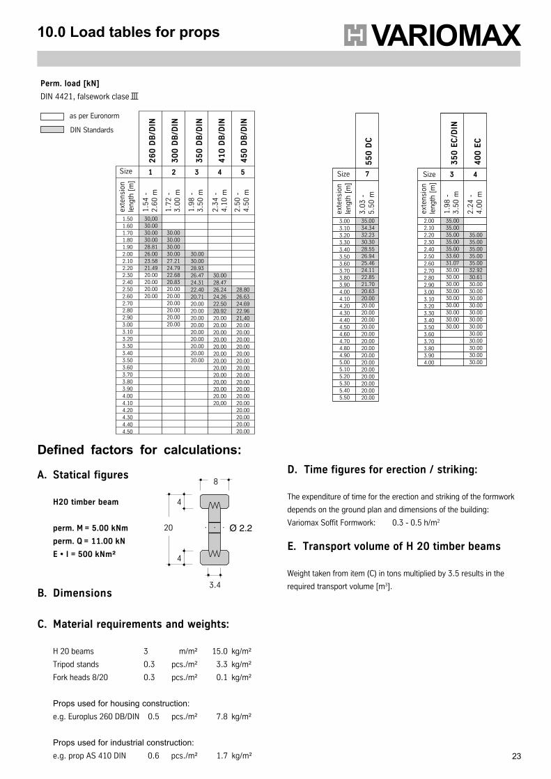
10.0 Load tables for props
8
3.4
Ø 2.2
4
4
20 ○ ○ ○
Defined factors for calculations:
A. Statical figures
H20 timber beam
perm. M = 5.00 kNm
perm. Q = 11.00 kN
E • I = 500 kNm²
B. Dimensions
C. Material requirements and weights:
H 20 beams 3 m/m² 15.0 kg/m²
Tripod stands 0.3 pcs./m² 3.3 kg/m²
Fork heads 8/20 0.3 pcs./m² 0.1 kg/m²
Props used for housing construction:e.g. Europlus 260 DB/DIN 0.5 pcs./m² 7.8 kg/m²
Props used for industrial construction:e.g. prop AS 410 DIN 0.6 pcs./m² 1.7 kg/m²
D. Time figures for erection / striking:
The expenditure of time for the erection and striking of the formwork
depends on the ground plan and dimensions of the building:
Variomax Soffit Formwork: 0.3 - 0.5 h/m2
E. Transport volume of H 20 timber beams
Weight taken from item (C) in tons multiplied by 3.5 results in the
required transport volume [m3].
30.0028.4726.2424.2622.5020.9220.0020.0020.0020.0020.0020.0020.0020.0020.0020,0020.0020.0020,00
26
0 D
B/D
IN
30
0 D
B/D
IN
35
0 D
B/D
IN
41
0 D
B/D
IN
45
0 D
B/D
IN
Size 1 2 3 4 5
exte
nsio
nle
ngth
[m
]
1.5
4 -
2.6
0 m
1.7
2 -
3.0
0 m
1.9
8 -
3.5
0 m
2.3
4 -
4.1
0 m
2.5
0 -
4.5
0 m
1.501.601.701.801.902.002.102.202.302.402.502.602.702.802.903.003.103.203.303.403.503.603.703.803.904.004.104.204.304.404.50
30,0030.0030.0030.0028.8126.0023.5821.4920.0020.0020.0020.00
30.0030.0030.0030.0027.2124.7922.6820.8320.0020.0020.0020.0020.0020.00
30.0030.0028.9326.4724.3122.4020.7120.0020.0020.0020.0020.0020.0020.0020.0020.00
28.8026.6324.6922.9621,4020.0020.0020.0020.0020.0020.0020.0020.0020.0020.0020.0020.0020.0020.0020.0020.00
Perm. load [kN]
DIN 4421, falsework clase III
as per Euronorm
DIN Standards
Size 7
exte
nsio
nle
ngth
[m
]
3.0
3 -
5.5
0 m
3.003.103.203.303.403.503.603.703.803.904.004.104.204.304.404.504.604.704.804.905.005.105.205.305.405.50
35.0034.3432.2330.3028.5526.9425.4624.1122.8521.7020.6320.0020.0020.0020.0020.0020.0020.0020.0020.0020.0020.0020.0020.0020.0020.00
55
0 D
C
Size 3
exte
nsio
nle
ngth
[m
]
1.9
8 -
3.5
0 m
2.002.102.202.302.402.502.602.702.802.903.003.103.203.303.403.503.603.703.803.904.00
35.0035.0035.0035.0035.0033.6031.0730.0030.0030.0030.0030.0030.0030.0030.0030.00
35
0 E
C/D
IN
4
2.2
4 -
4.0
0 m
35.0035.0035.0035.0035.0032.9230.6130.0030.0030.0030.0030.0030.0030.0030.0030.0030.0030.0030.00
40
0 E
C
Hünnebeck GmbHP. O. Box 104461, D-40853 Ratingen, GermanyPhone +49 (0) 2102/937-1, Fax +49 (0) 2102/[email protected], www.huennebeck.de G
B-1
2-04
-100
0-D
DH
1-1182.Aufbauanl.VariomaxD+GB 08.12.2004 10:57 Uhr Seite 3