SNS Integrated Control System Machine Protection Strategies for High Power Accelerators Coles Sibley...
28
SNS Integrated Control System Machine Protection Strategies for High Power Accelerators Coles Sibley SNS Controls Group May 15, 2003 PAC2003 2000-0xxxx/ vlb
-
Upload
eustacia-arnold -
Category
Documents
-
view
217 -
download
0
Transcript of SNS Integrated Control System Machine Protection Strategies for High Power Accelerators Coles Sibley...

SNS Integrated Control System
Machine Protection Strategies for High Power Accelerators
Coles Sibley
SNS Controls Group
May 15, 2003
PAC2003
2000-0xxxx/vlb

SNS Integrated Control System
Machine Protection Systems
“Machine Protection is not an objective in itself; it is a means to maximize operational availability by minimizing time for interventions and to avoid expensive repair of equipment and irreparable damage” (LHC MPS document)
» Protecting the machine» Protecting the beam(time)
» Providing the evidence» Target protection» Assisting operations» Conclusions
**** Machine Protection is not a personnel safety system

SNS Integrated Control System
Objectives - Protecting the Machine
Prevent damage to beam line equipment due to equipment failure or operator error.
Minimize radiation induced damage and minimize losses to allow hands on maintenance (ALARA).
Provide Maximum Allowable Interpulse Difference (MAID) systems for pulse-to-pulse permits.
Prepulse Beam Permit - Critical devices give permit just before beam, magnetics, kickers, dumps, vacuum etc.
Availability – MPS shut off the beam, reduced availability» MPS input bypassing or software masking depends on each Lab’s
policy, Policy depends on risks.

SNS Integrated Control System
Protect the Machine
Spallation Neutron Sources (SNS, ISIS, LANSCE, TTF)» High average power 1.4 MW, 1.4 ma average at 1 GeV
» High peak current (50 Amps, 645 nsec), proton density on target
» Loss limited, (10-4 losses) ALARA - Hands on maintenance
Linear Colliders (NLC)» Single Pulse Induced Failure
» 10 MW average beam power – Distributed losses cause radiation and thermal damage
» Beam collimation and MPS, problem for all future linear colliders
Large Superconducting Rings (LHC)» High current density, small beams
» 10 GJ stored Energy in magnets, 350 MJ per proton beam
» 10-8 Losses can impact operations

SNS Integrated Control System
Beam Loss Comparison Accumulator and Rapid Cycling Synchrotrons *
Machine Einj Eext Turns TypPpp
Loss(%)
ISIS 70 800 300 1.6e13 10
PSR (1) 800 800 2300 3.1e13 0.3
KEK-PSB 40 500 50 2.0e12 10
FNAL-B 400 8000 15 2.0e12 30
AGS-B 200 1900 200 1.5e13 28
IPNS 50 450 140 3.0e12 17
CERN-PSB(2)(Septum inj)
50 1400 15 perring
1.0e13 50
SNS (1) 1000 1000 1060 1.5e14 0.01
* J. Alonso, “Beam Loss Working Group Report” ,LBNL
SNS Integrated Control System
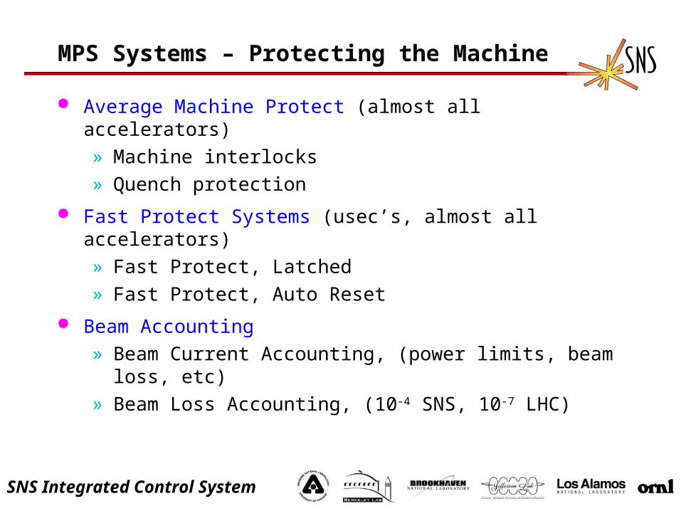
MPS Systems – Protecting the Machine
Average Machine Protect (almost all accelerators)» Machine interlocks» Quench protection
Fast Protect Systems (usec’s, almost all accelerators)» Fast Protect, Latched» Fast Protect, Auto Reset
Beam Accounting» Beam Current Accounting, (power limits, beam loss, etc)» Beam Loss Accounting, (10-4 SNS, 10-7 LHC)

SNS Integrated Control System
MPS Systems continued
Maximum Allowable Interpulse (Or Intra) Difference (MAID)» Verifies previous pulse parameters within tolerance
(position, loss, AP parameters)» Verifies prepulse systems are OK
– (Required for systems where beam cannot be aborted and single pulse will damage machine)
Post Mortem Analysis (Provide the Evidence)» Pinpoints cause of fault, initiates corrective actions
Beam Scheduling or Sequencing (Assist operations)» Limits beam power according to machine mode» Schedules appropriate beam for recovery from faults

SNS Integrated Control System
Beam Diagnostics used to Protect the Machine
Loss Monitors» Dynamic range, over 140 db,
ALARA, quench control» Beam loss limits, peak and
average
Beam Position Monitors» Nanometers to centimeters» Single bunch to CW» P-P position verification
Beam Current Monitors» Absolute - regulatory power limits» Integrated – average power limits» Differential – beam loss limits» Single Pulse – errant beams
New Technologies» Laser wires, beam in gap
measurements / clearing
Typical Fast Protect Systems
Fail safe design, detects internal faults, cable connection status, power supply faults, etc.
Remote self test and calibration capability
Controlled access of threshold parameters.
Heartbeat from timing system
Machine / beam mode aware
Circular buffers, waveforms on demand
Pulse to pulse (turn by turn) and deterministic

SNS Integrated Control System
Beam in Gap measurement with Laser (Saeed Assadi)
Expect to exceed 10^4 dynamic range, 3.8 ua between pulses
laser intercepting unchopped part of 32mA beam, 278 mv signal
laser intercepting chopped part of very low current beam 60 ua, 600 uv signal (20 dB amp), need 3.2 ua
PhotodiodeRaw BCM
Raw pickup signal

SNS Integrated Control System
MPS - System Integration [1] (NLC)
MPS Systems» Average
» Beam abort
» MAID
» Fast beam
abort
Global Timing
Abort Systems
Global Controls» Networks
» IOC’s
» Algorithms
User Interface
Pulse Sequencer
Avg MPS-Cooling-Vacuum-RadiationDetection
BA IN-Stoppers-Cooling-Vacuum-System in
MAID IN-BPM
FBA IN-RF-Kickers-Magnets-other
weightand
logic
weightand
logic
weightand
logic
weightand
logic
Process:Local / Global
Aborts
VerificationSystem
BroadcastSystem
BeamPermits
HardAbort
System
Displays Controls Logic
MPS Global Control Architecture
[1] Technical SystemsConfigurations -- Electrical
Subsystem: MachineProtection (MPS)
Author: R.S. LarsenRevision: 1
Date: April 13, 2001
380 PulsedIOC's
600 SlowIOC's
414 RFPulsedIOC's
60 MPS,Feedback,
Patterngenerator
IOC's
1000Supportnodes
300 Servers/Workstations
2800 cpu's >106 PV's
120 Hz, Pulsed Operation
High BW, low latency, QoS
Control System becomes “Pulsed”, ~1400 IOC’s
SNS Integrated Control System
IDMP:Q1
HEBT:DH11, DH12
LDMP:QH1, QV2,QH3-4, QV5-6
RTBT:DH13
EDMP:QH1,QV2
RTBT:QH26, QV27,QH28, QV29, QH30RTBT:DCH,V,26-30
RING:ExSptm11RING
RING:InjKH9A,BRING:InjKV9A,BRING:InjKH13A,BRING:InjKV13A,B
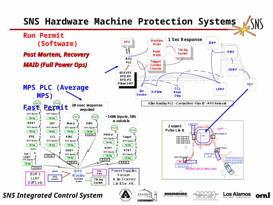
2 errantPulse Limit
SNS Hardware Machine Protection Systems
RING
RFQDrive
HEBT
Ldump
SRF
CCL
65 kV
RFQHVPPS
MPSMaster
Machinemode
RING
RTBT
Xdump
Idump
RTBT
Target
5.6 us
5.8 us
8.2 us
8.2 us
DTL (1)MPS Inputs
MEBT
RFQ
MPS Inputs
MPS Inputs
MPS Inputs
MPS Inputs
MPS Inputs
MPS Inputs
MPS Inputs
MPS Inputs
MPS Inputs
MPS Inputs
MPS InputsMPS Inputs
MPS Inputs
8.2 us
Src /LEBT
2.2 us
MPS Inputs
Power SuppliesVacuum
Wire ScannerLimit Sw. etc.
BLM'sLLRF
Diff I, etcTimingSystem
20 usec responserequired
~1400 inputs, 50%maskable
Timing
Timing
Timing
Timing Timing
Timing
Timing
Timing
Timing
Timing
Timing
Timing
Timing
TimingTiming
PPS ENTRY
IonSource
LDMP
IDMP
RING
EDMP
TGT
MPSPLC
PPS
ZO
NE
Sta
tus
65 KVPSRFQ-RFRFQ-PS
Plasma-RF
Allen Bradley PLC - Control Net - Flex IO - MPS Network
D-Plate
MachineMode
BeamMode
CCLBeamStop
TriggerControlChassis
TimingSystem
1 Sec ResponseRun Permit (Software)
Post Mortem, RecoveryPost Mortem, Recovery
MAID (Full Power Ops)MAID (Full Power Ops)
MPS PLC (Average MPS)
Fast Permit

SNS Integrated Control System
SNS Accelerator Timing Sequence
RTDL parametertransmission
Error detection>99.999994%
0-1 ms-2 ms 1 ms 3 ms2 ms 4 ms
RTDLtransmit "RTDL valid"
HeartbeatEvent
5 ms 6 ms
extract
beamaccumulation
Rf, High voltageGates
-3 ms
MPS InhibitPost_mortem
Trigger
Anytime
"Cycle Start"Heartbeat Event
Pre_Pulse Verification
Events
machine
Informational Events, no critical timing
Time Critical Events, (Hardware iscounting)
Master Trigger Generator
Inject
Absorbprepulse data
24 bit Frame, 8 bit CRC/MODE,(MODE*2+1),MODE
Frame255 - 24bit CRC
Prepulse_OK
Verify pulseparameters for
next pulse
Mode Masksin effect
FPAR Reset
1 - Time of Day (nsec)2 - Beam/Machine Mode3 - Previous Pulse Data4 - Timing System Status5 - Next Pulse ID
RTDL – Real Time Data Link
SNS Integrated Control System
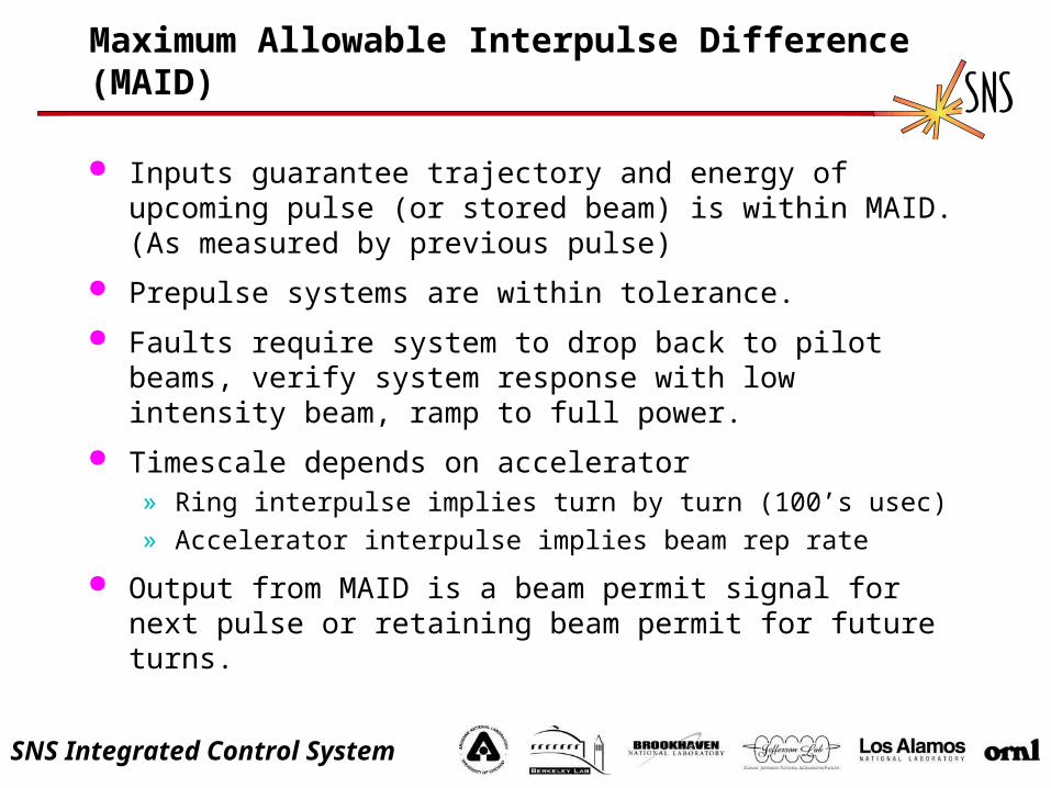
Maximum Allowable Interpulse Difference (MAID)
Inputs guarantee trajectory and energy of upcoming pulse (or stored beam) is within MAID. (As measured by previous pulse)
Prepulse systems are within tolerance.
Faults require system to drop back to pilot beams, verify system response with low intensity beam, ramp to full power.
Timescale depends on accelerator» Ring interpulse implies turn by turn (100’s usec)
» Accelerator interpulse implies beam rep rate
Output from MAID is a beam permit signal for next pulse or retaining beam permit for future turns.

SNS Integrated Control System
MAID at SNS 1.4 MW operations
Pulse to Pulse monitoring of: (MAID)» Linac RF parameters pulse average (phase and amplitude)» Injection painting» Phase space on target (BPM, etc.)» Integrated Beam Loss
Interleaved Pilot beams» Pulse stealing (every 60 sec) Verify painting, optics
Prepulse monitoring» Prepulse verification of magnetics, kicker status, etc.
Intrapulse monitoring, fast protect » Linac RF parameters (phase and amplitude)» Injection kickers» Beam loss» Integrated current
SNS Integrated Control System
Protect The Beam (Maximize Availability)
SNS is a neutron production facility for users (95 % Availability) Users schedule beam far in advance, experimental samples last
days?
LHC, Objective <= 1 faulty ABORT / 2 weeks, implies MTBF of 200 years/channel for 8000-10000 channels that can request abort.» Pwr converter failure, no quench 1.5 hours» Pwr converter and hysterisis, no quench 2.5 hours» Beam dump due to excess beam loss 1.5 hours» Beam loss causes dipole quench 5 hours» Sector warm up, equipment repair 4 weeks
Beam Interlock Controller» 15 conditional inputs, can be masked through control system
depending on machine status.» 16 non maskable inputs, vacuum valves, extraction OK, etc.

SNS Integrated Control System
Protect the Beam (reduce Downtime)
Reliability vs availability (Protect Machine without affecting Availability of Beam)
1. Redundant Systems
2. Voting schemes
3. Tolerant of non-critical system faults (allow reboots)
4. MAID windows reasonable for machine (low power, ignore windows)
5. Automatic recovery and startup
Reliability, Availability and Machine Protection Issues
Yanglai Cho, Tesla Collaboration Meeting, Daresbury Laboratory
September 23-25, 2002

SNS Integrated Control System
Provide the Evidence - Post Mortem Data
Post Mortem, reduce data, sort data, find what’s relevant.
Slow Data» Vacuum levels, water temperatures, line voltage, pressures,
temperatures, power supply readback’s, etc.
Diagnostics (waveforms on request, circular buffers)» BLM’s, fast, integrated, BPM’s, BCM’s, halo monitors
Pulsed Systems» Feed forward
» Phase, amplitude, FW,RV,RF power
» Ramped waveforms, injection painting, extraction kickers
Consider bandwidths required to correlate data Slow drifts leading to loss vs. inter pulse recoverable fault

SNS Integrated Control System
Post Mortem Data Correlator (Beam Loss)
Uses time stamps to ensure data collected is from same pulse
Limits data search to small sections of machine, hierarchical.
Limits amount of data archived by storing waveforms in circular buffers, for N previous pulses
Provides evidence of equipment running outside of limitsrequired for stable operation.
Allows a subset of datato be made available to AP applications for instability analysis
VME Loss
BPMBCM BPM BCMLLRF
DTLBCM
CCLBCM
LB_SCLLLRF
HB_SCLLLRF
RTBTBPM
RTBTLossRing
Ph_SpaceLinacLoss
BCM'sHB_SCL
BPM
CorrelatorTool
EVENT Master
Machine ProtectionFault
BPM
VME Loss
BCM
MPS FaultEvent
M_Beta WFCorrelator
SNS Integrated Control System
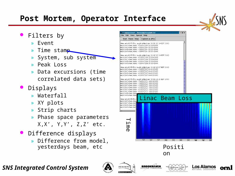
Post Mortem, Operator Interface
Filters by» Event» Time stamp» System, sub system» Peak Loss» Data excursions (time
correlated data sets)
Displays» Waterfall» XY plots» Strip charts» Phase space parameters
X,X’, Y,Y’, Z,Z’ etc.
Difference displays» Difference from model,
yesterdays beam, etc
Tim
e
Position
Linac Beam Loss
SNS Integrated Control System
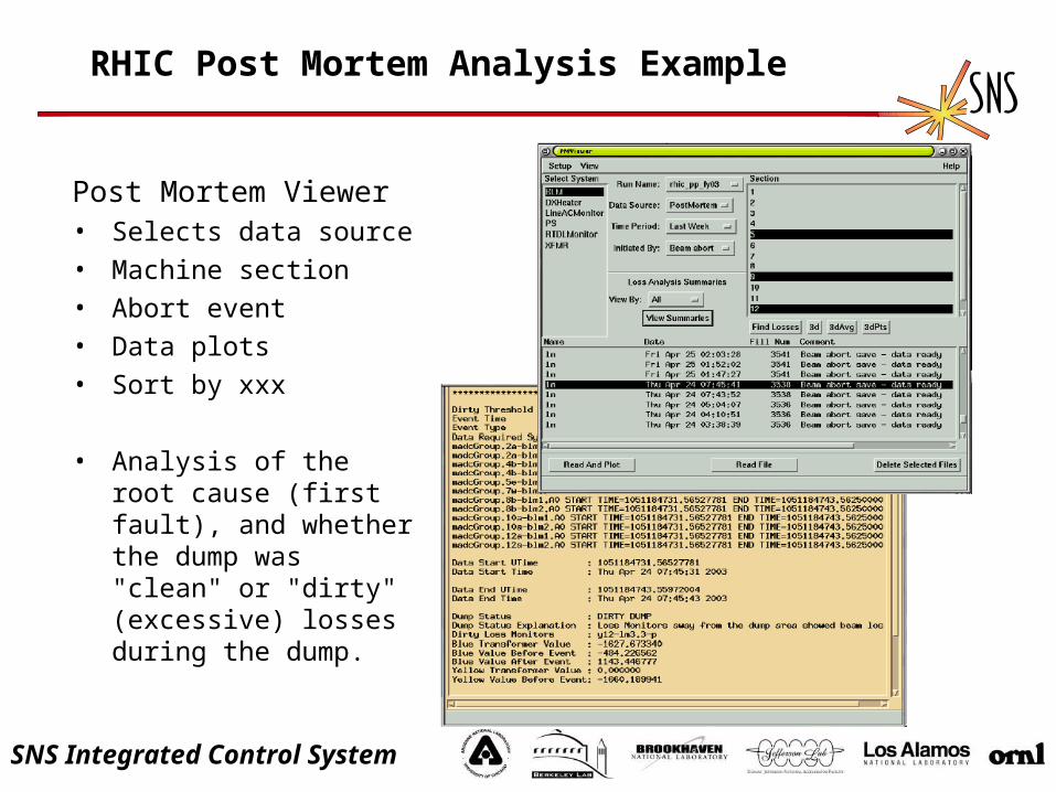
RHIC Post Mortem Analysis Example
Post Mortem Viewer• Selects data source
• Machine section
• Abort event
• Data plots
• Sort by xxx
• Analysis of the root cause (first fault), and whether the dump was "clean" or "dirty" (excessive) losses during the dump.

SNS Integrated Control System
Loss Monitor PM Data
• Post Mortem viewer finds excessive losses• The graphs show losses around the time of the MPS trip
(labeled as time 0).• Losses occurred before T0 => Losses in these areas tripped
MPS.
SNS Integrated Control System
Summary – Protect Beam, Provide the Evidence
Quench Protection, beam inhibit / dump for super conducting accelerators / rings, minimize false trips
Tolerate reboots – Systems not involved in pulse-to-pulse feedback, MAID.
Provide power limit protection for targets / beam dumps
Provide (schedule) diagnostic pulse(s) for commissioning or pilot beam for recovery from faults
Provides evidence from cascaded faults as to source of problem (post mortem analysis)
Fault recovery automatic, fault detection easy for operations
SNS Integrated Control System
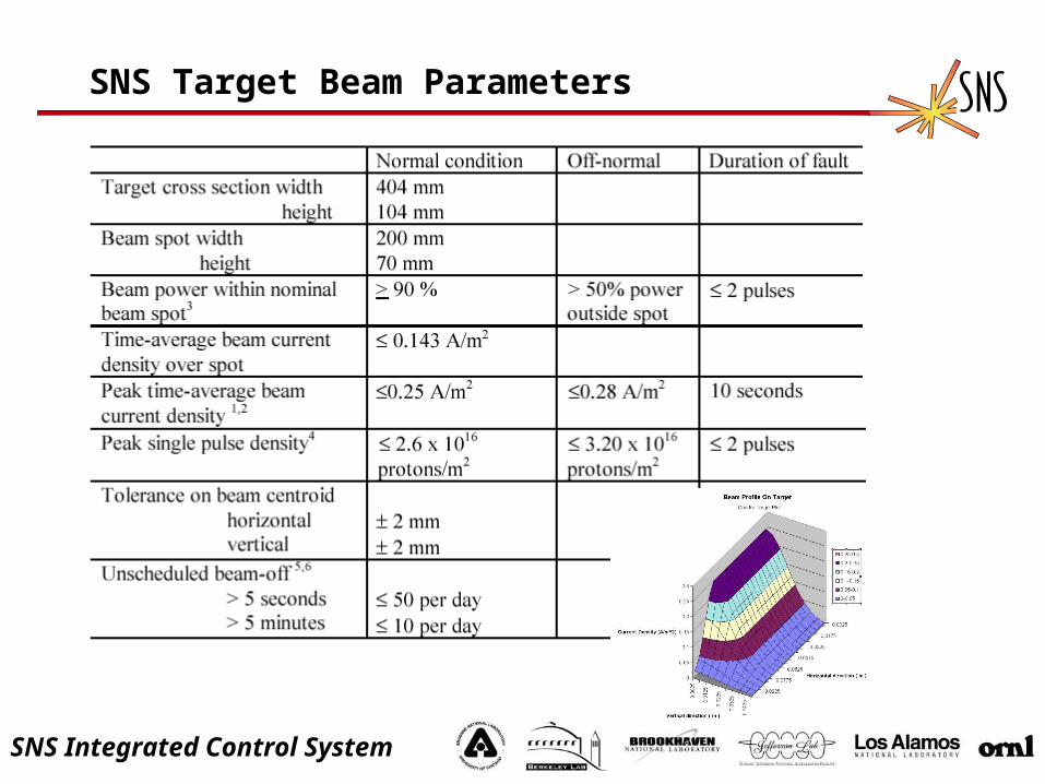
SNS Target Beam Parameters

SNS Integrated Control System
Beam on Target Monitoring
Accelerator Physics fault studies determine redundancy requirements
Accelerator Physics models, commissioning results define acceptable pulse-to-pulse parameters
Prepulse system verification active.
Monitor parameters with pilot beam
Set MAID windows, redundant PS monitor windows
MAID active
Ramp to full pulse width, rep rate.

SNS Integrated Control System
Assist Improving The Operation (SNS)
Minimize # of screens required to locate and reset faults. Transition latched faults to auto reset as systems mature and
faults are understood. Recover from fault, log data, and bring machine back on line in
diagnostics mode (commissioning) Recover to full power using power ramp up (2007)
SNS needs high level screens and Alarm handlers for commissioning.
Partner labs provide engineering screens!

SNS Integrated Control System
Conclusions
Machine Protection is more than an interlock chain. Tight integration with the timing system, control
system, RF systems, Beam Abort systems, and diagnostics is essential.
Control System Performance essential, QoS etc. Post mortem systems integrated during
commissioning will reduce troubleshooting time later. Automatic recovery from faults will increase
availability Think of MPS as a diagnostic for the accelerator, not
just a means of turning off the beam.

SNS Integrated Control System
References:
The Beam Inhibit System for TTFI, Draft to be submitted to DIPAC 2003 , D. Nölle, P. Göttlicher, R. Neumann, D. Pugachov, K. Wittenburg, M. Wendt, M. Werner, M. Staack, DESY, Hamburg, GermanyM. Desmors, A. Hamdi, M. Jablonka, M. Loung, CEA, DAPNIA, Saclay, FranceH. Schlarb, SLAC, Stanford, USA, e-mail: [email protected]
Beam Intensity Monitoring and Machine Protection By Toroidal Transformers on the Tesla Test Facility, J Fusellier, CEA, DSM/DAPNIA/SEA, CE-Saclay, F-91191 Gif-sur-Yvette
The Next Linear Collider Machine Protection System, M. Ross, SLAC PAC1999, New York
Surveille Protection of a 150 kW Proton Beam Dump, L. Rezzonico, Paul Scherrer Institut, PSI, Switzerland, BIW00
High Stability Operation of the ISIS Pulsed Spallation Neutron Source at 200 uA, C. Planner, Rutherford Appleton Laboratory, Chilton, Didcot, Oxon, U.K., EPAC96
Overall Design Concepts for the APS Storage Ring Machine Protection System, A. Lumpkin, Argonne National Lab, Argonne IL

SNS Integrated Control System
`
RHIC Beam Permit and Quench Detection Communication SystemC. Conkling Jr, Brookhaven National Lab
Machine Protection Schemes for the SLC, M. Ross, Stanfor Linear Accelerator Center, Stanford CA, PAC 1991
Machine Protection System Algorithm Compiler and SimulatorG White, SLAC PAC1993
NLC – Machine Protection System: Global Requirements, J. Frisch
NLC Global Controls Architecture, R. Humphrey 5/25/99
Machine Protection for NLC, J. Frisch, Feb 24, 1999
Zeroth Order Design Report for the Next Linear Collider (Ch. 16)
Interlock and Protection Systems for Superconducting Accelerators: Machine Protection System for the LHCR. Schmidt, CERN Geneva Switzerland (pge 170)
A High Stability Intensity Monitoring System for the ISIS Extracted Proton Beam, M Clarke-Gayther, RAL, Didcot U.K.