SN:AVSHIPS - Defense Technical Information Centerdtic.mil/dtic/tr/fulltext/u2/680042.pdfINTRODUCTION...
239
SN:AVSHIPS TRANSLATION NO. 1148 SMIP .BOLLS MADE OF REINFORCKD OOXNCRETE ( (Korpusa sudov iz amotsementa) "(Design, Strength, and Construction Technology) V. F. Bezukladov, Y. K. Amellyanovich V. D. Verbitskiy, L. P. Bogoyavlenskiy G 229 p. Scientific Editor: VoF. Bezukladov Shipbuilding Publishing House, Leningrad 1968 - 187 pages RUSSI IN Translated by Lloyd G. Robbins Vienna, Virgin'ia D 07 C JJAN 6 1968 JJJ C DISTRIBUTION OF THIS DOCUMENT IS UNLIMITTED N NAVAL SHIP SYSTEMS COMMAND S~DEPARTMENT OF THE NAVY ~'~EMSWASHINGTON,D.C. 20360 C~M P NOE4E 196 to ,Ib' , ie ,
Transcript of SN:AVSHIPS - Defense Technical Information Centerdtic.mil/dtic/tr/fulltext/u2/680042.pdfINTRODUCTION...

SN:AVSHIPS TRANSLATION NO. 1148
SMIP .BOLLS MADE OF REINFORCKD OOXNCRETE( (Korpusa sudov iz amotsementa)
"(Design, Strength, and Construction Technology)
V. F. Bezukladov, Y. K. AmellyanovichV. D. Verbitskiy, L. P. Bogoyavlenskiy
G 2 2 9 p.
Scientific Editor: VoF. BezukladovShipbuilding Publishing House, Leningrad
1968 - 187 pages
RUSSI IN
Translated byLloyd G. RobbinsVienna, Virgin'ia D 07 C
JJAN 6 1968 JJJC
DISTRIBUTION OF THIS DOCUMENT IS UNLIMITTED
N NAVAL SHIP SYSTEMS COMMANDS~DEPARTMENT OF THE NAVY
~'~EMSWASHINGTON,D.C. 20360
C~M P
NOE4E 196 to ,Ib' , ie ,

TABAE OF CONTENTS
- Page
CONVENTIONAL SYMBOLS ........................................ i
INTRODUCTION . ................................................ 1
CHAPTER I. PROPERTIES OF REINFORCED CONCRETE AS A SHIPBUILDINGMATERIAL .............................................. 12
Section 1. Structure of Reintruced Concrete ................. 12Section 2. Component Materials of Shipbuilding Reinforced
Concrete . ............................................. 1.4Cement-Sandy Concrete ............................. 14Reinforcement ....................................... 17
Section 3. Effect of Various Structural Factors of t)eDeformative ans Strength Properties of ReinforcedConcrete .............................................. 21
Effect of Reinforcing Rods upon the Deformativeand Strength Properties of Reinforced Concrete .... 26
Effect of Grade of Concrete and Depth of ProtectiveConcrete Layer upon the Deformative and StrengthProperties of Reinforced Concrete .................... 28
Section h. Strain State and Crack Formation of ReinforcedConcrete During Axial Expansion and Bending ............. 30
Axial Expansion and Expansion During Bending ........ 30I. Sector of Elastic Stresses of Reinforced
Concrete ....................................... 31II.Sector of Origination and Development of Micro-
cracks ......................................... 32III. Sector of Formation of Visible Cracks ........ 34Compression During Bending .. ...................... 37
Section 5. Strength of Reinforced Concrete During CentralCompression ........................................... 39
Section 6. Deformability of Reinforc,:d Concrete UnderProl.onged Effect of Load .............................. ho
Section 7. Strength and Deformability of Reinforced Con-crete During Shear .................................... h3
Section 8. Functioning Capability of Reinforced Concrec eDuring impact ......................................... 50
Section 9. Watertightness of Reinforced Concrete .......... 55Section 10. Resistance of Reinforced Concrete to
Freezing .............................................. 59
CHAPTER Ii. DESIGN OF VESSELS MADE OF REINFORCED CONCRETE... 61Section 11. Most Typical Examples of General Composition
of Reinforced-Concrete Hulls .... ...................... 61
A

Page
Reinforced Concrete Ships with Hulls Made in theForm of Circular Unframed Cylindrical Shells ..... 62
Reinforced Concrete Unformed Hulls in the Formof Simplified Shells ............................ 63
Reln'orced Concrete Hulls with FerroconcreteA%.sembly Beams ..................................... 65
Reinforced Concrete Hulls with Framing in the Formof Flat Reinforced Concrete Membranes ........... T7
Section 12. Design of Marine Reinforced Concrete Plates.. 77Section 13. Framing Beams .................................. 80Section 14. Intersectional Joints ......................... 84
Connections in one plane ............................ 84Corner tee and four-way Joints ....................... 89
Section 15. Reinforcement to the Reinforced ConcreteHull of Internal Saturation of Vessel ................ 96
CHAPTED III. )TECHNOLOGY OF PRODUCING THE DESIGNS AND HULLSOF VESSELS FROM REINFORCED CONCRETE ................... 109
Section 16. Effect of Reinforced Concrete on Selection ofMethod for Building a Vessel .......................... 109
Section 17. Basic Features of Engineering in the Con-struction of Reinforced Concrete Vessels .............. ill
Preparation of Reinforcing Material ............... 112Assembly of Reinforcing Frames ..................... 113Preparation of Concrete and the Concreting of
Designs ......................................... 115Heat-Moisture Treatment of the Concreted Design .... 119Assembly of Hull on the Slipway .................... 119Attachment of the Inside Equipment of the Vessel to
the Reinforced Concrete Design ................... 120Application of Anticorroii- Coatings to the
Reinforced Concrete Sheathing of the Hull ........ 121Section 18. Examples of Construction of Reinforced Con-
crete Vessels by the Monolithic Method ............... 124Section 19. Examples of Building Reinforced Concrete
Ships by the Prefabricated and Prefabricated-Mono-lithic Methods ....................................... 131
CHAPTER IV. ESTIMATING THE STRENGTH OF VESSEL DESIGNS OFREINFORCED CONCRETE HULLS ................................. 143
Section 20. Description of the Methods of Estimating theStrength of Reinforced Concrete Designs ............... 143
Section 21. Design of Beams, the Material of Which DuringElongation and Contraction Follows the Hook Lay, butDuring Elongation the Elasticity Modulus Does notEqual the Elasticity Modulus During Contraction ....... 151
Distribution of Standard Stresses .................. 151Dist~ibution of Tangential Stresses ................ 155
II

Section 22. Estimttion of Bearing Capacity of Rein-forced Concrete Elements of Hull Designs Based onFormulas for Calculating the Ferroconcrete Designs.. 157
Section 23. Results of Tests for the Strength ofShip Designs Made of Reinforced Concrete ........... 180
Section 24. Substantiation of the Ptandards of theDangerous and Permissible Stresses for theMarine Reinforced Concrete Designs .................. 194
CHAPTER V. STATIC TESTS OF THE STRENGTH OF REINFORCEDCONCRETE HULL OF A FLOATING CRANE
Section 25. Purpose and Problems Involved ir theTests ............................................... .. 197
Section 26. Procedure used for Conducting theTests ............. ....................... .. 199
Section 27. Results Obtained from the Tests .......... 205A1PPEN IX .. , *.. *.. . o.. . .*. . .. . . . .. 0. .. . . . . .0.. . . 214
B I B L I 0 G R A P H Y . . . . . . . . . . . . . . . . . . . . . . . 225
j III

CONVENTIONAL SYIMOLS
R m- standard tensile strength of reinforced coTorete
Rc - standard compressivo strength of reinforced concrete (prismaticstrength of concrete)
R1-;ft. c, -m standard tensile ano compressive strength of reinforced con-crete during flexure
Rc, - standard shear strength of reinforced concrete
Rcp f standard cutoff strength of reinforced concrete
Ra a design strength of extended roa -ramevork (reinforcement) usedfor reinforcing the concrete
E - modulus of elasticity of reinforced concrete under axial elong-attion
Ec - modulus of elasticity of reinforced concrete i-nder axial com-press ion
E.p." ;Ec, - reinforced concrete's modulus of elasticity fir expansion and
contraction during flexure
Sa modulus of shear for reinforced concrete
- = coefficient of relative eransverse deformation of reinforcedconcrete (Poisson coefficient)
iiaa" - volumetric weight of reinforced concrete
,I." -volumetric weight of cement-sandy concrete
Kn . specific surface of reinforcement (total surface of wire ingrids per unit of voluui .-,- reinforced concrete element)
A m- coefficient of reinforcement (ratio of area of cross sectionof longitudinal reinforcement to cross sectional area of ele-ment)
= - actual length of design's element
10 W computed length of design element under calculation for stability
b - least dimension of rectangular cross section of element
r - minimum radius of inertia of element's cross section

INTRODUCTION
Among the design hull materials in use for shipbuilding, a specific
place is occupied by ferro-concrete and one of its variants, i.e, reinforced
concrete.
The substantial savings in metal (by two-three times) realised the con-
struction of the hulls of floating structures of reinforced concrete, at a sim-
ultaneous substitution of expensive and scarce sheet and profile rolled iron,
with reinforced rod steel, establishes that unvarying interest which is ex-
pressed in ferro-concrete in shipbuilding. Just as much interest in the float-
ing facilities with ferro-concrete hulls is also manifested by the operating
organizations, since in distinction from the structures with steel hulls, the
designs with ferro-concrete hulls do not require layovers in dock for painting
the hulls and for the periodic replacement of rusted plates of sheathing and
elements of a set, lhich saves considerable resources. In spite of the circum-
stances noted above, confirned by the construction experience and the subse-
quent operation of the ferro-concrete floating facilities, as a whole for the
ferro-concrete shipbuilding for the past 50 years, we have typically had both
periods of abrupt increases, and periods of equally abrijpt declines, Including
the complete shutdown of this type of floating facilities.
Such an instability in the development of the ferro-concrete shipbuild-
ing, in addition to the purely subjective factors (and in a number of cases, of
outright prejudice), has been established mainly by the absence of the necessary
objective conditions for the regular construction of ferro-concrete hullc reli-
able in operation.
The seemingly simple organization of construction, the simplicity of the
production processes under the possible utilization of specialists with relatively
-1-

low skills have inevitably involved the appearance of superfluousLy overheavy,
over-reinforced hulls with a low quality of concrete, cracking under the ef-
fect of atmospheric moisture, -luctuations in temperature and in sea water.
A time was required sufficient In r that the basic conditions, determining
the reliable operation of the marine ferro-concrete hulls, were revealed, under-
stood and strictly regulated. Beginning from 1955, as a result of the accom-
plistment of a series of scientific-research, planning and testing-design act-
ivities, the necessary scientific base was created for developing the plan of
ferro-concrete ships and for the selection of the most effective engineering
processes for their building.
The systematic studies which were conducted established the necessary
extents of reinforcing the main and secondary design elements, the principles
of efficient design configuration; standard documents were developed Z:r all
types of work in the assembly and concrete reinforcing both of the individual
sections, and of the entire hull as a whol*; the specific requirpznnts were
determined and delineated on monittrirq the qualities of the 'Inished products.
As a result of the r*search activities, it was demonstrated that the conditions
of wveking on concrete, reinforced htills, situated in sea water under constantly
changing loads (in ueotnt and suIn), the requirnwnts of resistance to freesing,
complete airtightness end rellatle resistance to the aggressive effect of see
water basically! distingis'i8a the floating river and naval fearro-concrete facil-
ities from any civil installations, including the hydrotS :hnical ones.
The book brought to the attention of the readers con!ained a brief dis-
cussion of the basic results of the activities and studies conducted by the ship-
building scientific-research organizations, the design buL 'us and the shipyards
engaged in reinforced concrete shipbuildinx, with the develovent of design cri-
teria and engineering processes necessary . 'ning and bulici,-g the hulls of
floating facilities made of reinforced conct,.e.
-2-.

The book also presents data from published reports (or reinforced con-
crete) issued by the leading specialized organizationsi the NIIZHB of the
USSR Goestroy, the Len ZNIIEP, the NIISK Goestroy of the USSR, the TNIISGKI,
the ISiA of the Byelorussian SSR Academy of Sciences and the NIIsel'stroy.
The technical advantage of using rtinforced concreta in the designs
of the hulls and superstructures of ships has been confirmed by the exper-
ience gained in the construction and operation of various reinforced-concrete
ships in our country and abroad.
Tn the building cf the first ruinforced-concrete ships , initially
there was a definite uncertainty in the new shipbuilding material, especially
in respect to the capability of the elements to function during ImP4uct and
sign-chanring loads.
In spring of 1943, in Italy extensive research -nd experiments Vere
conducted under the supervision of the Naval administration. The purpose of
the experiments vas the establishment of the actual valu % of the physico-me-n-
anical characteristics of reinforced concrete under the effect of permanent and
ilpa-t (shock) loads. The experimental plates with a dimension of 1.5 X 1.5 a,
vith a thickness of 30 s, reinforced by thin wires with a total expenditure of
metel amounting to 400-500 kg per cubic meter of concrete, were tested by drop-
ping a load on ttem weighing 260 kg from a height up to 3 meters. At this time,
it vas established thac even vith the presence of small and partial cracks, in
the region of strain, the plates retained their vater tightness.
The construction (begun in 1•43 by the Nervi and Saroli Firm) of three
motor-driven transport stips for the n;-,-- and a motor-driven transport ship
with acar.ocaDoaety of 400 tnns wes Interrupte' )v"ng to the war. The con-
struction was renewed in l940 at the Laztartnl and Meacn, -hipyard in Anslo.
The motor-driven speed sailbo. wIrene i with a capacity of 165 tans was built
i -3-
ii

in three months (Fig. 1). The thickness of the hull sheathing on the "Irene"
equalled 35 Se. The plating was made of eight laye'- of reinforced screens
with a grid isze of I cm and a weight of I kg/m 2 . Four layers of the screens
were located closer to the external, and four layers closer to the inner sur-
faces of the plating. Between the layers of screens, three rows of steel re-
Inforcing rods with a diameter of 6 m were placed, arranged 10 cm from each
other. The reinforcement Rrids and rods were t!ghtly interconnected by a steel
wire; in the preparatlon of the cement-sandy solution, for the plating, 1000
kg of cement per cubic meter of concrete were used. The placement of the ce-
ment-sandy solution on the gr.ds was accomplished manually (by workmen) from
the inside of the hull. The shaping of the hull wda accomplished without the
application of cement forms.
./
Fig. 1. Motor.Ortven Reinforced Concrete Sailboat "Irena".
The experience gained in operatinp o ships removed all doubt In re-
spect to reinforced concrete as a shipbuildidgx h-Al material. "i sP-.ipe dem-
onstrazed high operational-technical qualities. After 1lO-0 years of operation,
the hulls ver# in good condition, without showin-w any appreciable damsgee. The
motor sailboat "Irene" durinn the operating period from 1945 to lQ58, moking
regular cruises under stormy conltion5 between varoojs Italian ports, did not
have any significant damages. The occasional damages to the hull from collisions
-4-

during docking were only local blind cracks without loss of the water tightness
of the plating. Such damages were repaired by the crew without putting the ship
out of operation.
Cl
Fig. 2. The Reinforced-Concrete Fishing Trawler "Santa Rita".
Other reinforced-concrete s!is built In Italy from 1945-19•6 (the
excursion yacht "'ennele", having a hull piating thickness of 10.12 M, rein-
forced by seven layers of gratings with a mesh size of I cm and a weight of
I kg/i2, the fishing motor-driven - "Santa Rita" w'th a eadweight of 165
tons, rig. 2), is still in operation.
In hull weight, the concrete-reinforced . built in Italy ire 5-
10" lighter than the wooden hulls of similar sti:,s, while their cost proved
to be less hv 40..I,..
The reinforced-concrete navigational lnurches (FtFi. )) built by the
British firm 4ndhbosts are eq-zal in t1eir o:erational-teclnical indexes to the
same launches with a hull made of wood or steel. They; have a lighter hull,
equally as strong as a steet hull. The ex-enditures for the c.nstruction of
the reinforced-concrcte launches prove to he h ,hs:ar iallv lower khy 55-,1R.)
than the costs for hulldlni the launchcP witi a huil Aacde of stoel, wood and

fiberglas. The low operating costs and the simplicity of repairing the rein-
forced-concrete hulls increase still mere their economic effectivernss.
The repa'r of occasional accidental damages to the hull of the cutters
wee as a rule conducted b" the crews. Thus, one of the cutt-ra, as a result
of a collision of a yacht in its stem, sustained damage in the amidships revion
with a dimmnuior, of 0.75 X 0.61 m. At Lhis time, the maximim sagging of the
reinforced concrete plating rer:iA'vi 4 cm. After the elimination of the sag-
ging with the aid of a hydraut.- Jack, in the plating we found only minor
cracks with a depth up to 3 amm. The damage was repaired uvth cement-sandy con-
crete in 30 minutes.I Ii
Fig. 3. The Reinforced-Concrete Sport Launrh Built bý theWindboats Firm.
! qually as high operating qualities were also shown by the reinforced-
concrete ships built in our :ountry. On 1 July 1957, we launched on the Volga
River the first reinforced.concrete yacht "Opyt" (Experience). As is described
by engineer I. Ya. Clan, "The first reinfor-ed-concrete yacht 'Opyt' in late
&utumn 1937 was torn from anchor during, a severe storm and was thrown onto the
rocks on the opposite snore. We were unable to remove the yacht because of the
Ict ism which had started. The entire autumn, the hull of the yacht was on the
rocks, and during the winter it froze into the ice. In the spring, at first
glance the hull of the yacht had a sad appearance. The sides were crumpled,
buc nelertheless the reinforced gratings proveC to be undamaged. All that was
-6.

required was the work of four men, a bag of cement and several buckets of river
sand in order for the yacht hull to be repaired in one day".*
The yachts "Tsesntai", "ProgresS", "Mechta" and the launch "lnergostr-
oitel" also proved themselves well during operation.
For three navigational seasots, the yacht "Tsemental" cruised under the
moat diverse navigating conditions for more than 2,500 miles along the Dnieper
River and tle Black Sea. The hull of the yacht proved to be quite strong and
waterproof.
On the yacnt "Mechta" during the navigational season of 1965, the long
t-ip was maade along the Volga from the port of Togliatti to the port of Kagan.
Diring the trip, mostly during a wind of force 7.8 points, the yacht showed
high navigating qualities and the ,:)sence of any damages to the hull.
Fig. 4. Hauling the Finished Reinforced-Concrete Hull of the Yacht
"Progress".
In weight of hull, the reinforced-concrete yachts are not inferior to
the wooden ones, while in cost of construct 'on they are cheaper by 5 times.
Specifically, the cost of building the hull of the yacht "Progress" (Fig. 4)
was around 900 rubles, and in tl. materials for the hull, around 200 rubles
were spent. The weight of the hull of reinfo-ced-concrete yacl.s comprises
40.45% of their displacement, or 50.55 kg per unit of cubic modulus of the
LBH. The ballast weight for yachts made of reinforced concrete comprises
30.35% of the displacement.
*I. Ya. Clan. Flying Rock, "Inventor and Efficiency Expert", No. 7, 1962.
.7-

K
The data presented show that the weight characteristics of the concrete-
reinforced yachts are somewhat lower than in the same type of wooden yachts.
As the calculations indicate, the application of reinforced concrete
for building yachts proves to be quite Justified, if they are longer than 8
meters. At a yacht length of less than 8 a, the hull made of reinforced con-
crete proves to be heavier than the wooden one. With an increase in the dimen-
sions, the weight of the hull of a reinforced-concrete yacht in relation to the
wooden one decreases, and at a yacht length of 15.20 m, it comprises a value of
the order of 15-20%.
In 1964, in our country we built r -elf-propelled driftwood hoisting
crane equipped with a reinforced-concrete hull and a superstructure (Fig. 5).
During the planning of the crane, the form of the configuration and the m-in
measurer-nts of the hull were not changed as compared with the floating crane
having a metal hull, which was reflected on the technical-operating qualities
of the ship. Thus, the draft of the reinforced-concrete ship proved to be
greater than in the metal prototype. Naturally, this could have been avoided
by having increased slightly the principal measurements of the reinforced-con-
crete hull as compared with the steel hull. With an increase in the draft of
the reinforced concrete hull, its resistance to movement increased, whereas the
main engines and the propulsion unit were taken to be the same as in the metal
prototype. The latter circumotance led to a deterioration in the controllabil-
ity of the floating crane and to a slight riduction in the travel speed. How.
ever, in spite of the errors permitted during the planning of the ship, the
economic advantage of using reinforced concrete in place of steel as a materiAl
for the ship hull was confirmed. In this connection, the consumption of steel
was decreased by more than twice, and the cost of building the hull was reduced
by 107. as comparad wi t h building the metal hulls.
.- 8.

Table 1
Indexes of the Hull Weight and Use of Steel for the Metal Barges, Bargea ofStandard, Ferro-Concrete, Prestressed "Keramit"-Concrete and Reinforced Concrete
2)ta Weight
"d*Lt of stu*.eiglit ofof reza- par tm Wll paf ooeemt at Car- ton of
Yope 4 vesml "erisl ToeW vol- or ahest p OV- sango ft.dosfti pro- aoty. oqpmdt.
steel for
In bun.l a3 inn5
trine dry-cargo standard 70.5 34.0 0.11 0.58 one barge wyaarge with hols- ferro- built from:ing capacity of concrete 1943-194400 tons
marine dry-cargo the same 120.0 46.5 0.09 0.65 more than 25barge with hois- barges wereting capacity of built from500 tons 1948-1955
marlne dry-cargo steel ---- 129.0 0.32 0.32 based on databarge with hots- from B.V. Bog-ting capacity of danov. Sea &400 tons Harbor barges,
Sudprougi s.1963
eagoing liquid standard 230.0 100.0 0.10 0.60 technicalargo barge w/ ferro. project
hoisting capac- concreteity of 1,O00tons
peagoing dry. the same 298.0 138.0 0.11 0.60 the samecargo barge withlifting capacityof 1300 tons
seagoing dry- steel ---- 320.0 0.32 0.30 based on datacargo barge with from B.V. Bog-lifting capacity danov. Seagoingcf 1000 tons & i 6 harbor bargs',
Sudpro iz, 1963
-9.

to tvesse 64 -dI-r
in
4mtfj
harbor liquid standard 272.0 136.0 0.10 0.49 two bargescargo barge with ferro- were built
lifting capacity concrete from 1945-
of 1400 tons 1947
barge-platform reinforced con- 91.3 38.0 0.06 0.40 predesign
with lifting crete for plates processing
capacity of of sheathing of600 tons bottom, side &
longitudinal bulk.heads; the remain.ing parts are mad
of kerainit-ferro,concrete
barge-plattorm prestressed 116.3 28.0 0.05 0.40 one bargewith lifting keramzit-con- was built
capacity of crete in 1962
600 tons
reinforced con- reinforced 102.0 51.1 0.05 0.27 was builtcrete barge v/ concrete in 1965 inlifting capacity Czechos lovakia
of 1000 tons(Czechos lovakianSocialistRepublic)
-10-

Fig. 5. Reinforced-Concrete Floating Crane with a HoistL,4
Capacity of 10 Tons.
At the present time, the crane is operating without any restrictions
in the lower reaches of the Volga River, after two years of operation, its hull
is still in excellent conditlo!:s all of the high quality elements made during
the construction are watertight and do not have any signs of corrosion,
The significant decrease in the weight of hull permits us to utilize
effectively the reinforced concrete for the construction of certain types of
transport ships, for example barges.
In 1965, in Czechoslovakia, a double-hull reinforced.concrete barge
with a lifting capacity of 1,000 tons was built. The weight of the reinforc-
ing steel (gratings and rods) used in building the 6arge amounted to 51 tons.
The weight of the hull in the concrete-reinforced barge referred to one ton of
lifting capacity, equals 0.273. The value of the indicated coefficient prove@
to be close to its value for the metal barges similar in lifting capacity(Table
1). The consumption of metal for building the hull of the reinforced-concrete
barge proved to be three times less than in building the hull of a similar metal
barge.
The accumulated experl ice in building and operating the reinforced-
concrete 'ihips in our country and mbroad permits us to establish that rein-
forced-concrete can be applied effectiveiy as a hull material for the transporti,
-Il-

fishery, sporting and other ships with a displacement up to 1,000 tons. The
reinforced-concrete is also suitable for broad application in the hulls of ferro-
concrete ships as a materiel for making the 'tweendecks', superstructures, deck-
houses, etc.
As a result of its resistance to fire, the increased sound insulating
capacity and the low heat conductivity, reinforced concrete can be also used
successfully in the steel hull as a material for bulkheads, partitions, plat-
form and foundations.
CHAPTER 1. PROPEITIES OF REIN.FORCED CONCRETE AS A SHIPBUILDING MATERIAL.
Section 1. Structure of Reinforced Concrete
As a variant of ferroconcrete, reinforced concrete differs from it in
its structure.
Ordinary ferroconcrete consists of concrete, reinforced by individual
rods or by reinforcing grids, as a rule located in the action sone of the tensile
forces. In this connection, reinforcement rods, the diameter of which amounts
to 1/8 - 1/10 of the thickness of the ferroconcrete element of a ship design,
increases the heterogeneity inherent to concrete. To obtain reinforced concrete,
we utilise cement-sandy concrete and thin metal fine-meehed wire, uniformly placed
along the section of the design element.
The ship ferroconcrete designs are reinforced vith rods having a dia-
meter of not less then 6 mn. The rods or grids vith a smaller diameter of re-
inforcement in the ship design of standard ferroconcrete can not be used,
since they do not met the strengith requirements under the observance of the
conditions of the technological development (a specific distance between the
reinforcement rods, the required stiffness of the reinforcing frames).
-12.

The metal grids which are used for the reinforced concrete have a dia-
meter of rods equalling 0.7-1.2 -m, which comprises 1/30-1/40 of the thickness
of the element of the vessel reinforced concrete design. The mesh sizes of such
grids equal 5.12 mm, whereas the mesh size of the rod gratings which are utilized
for reinforcing the ship designs made of standard fertoconcrete comprise 50o100
mNe
By a uniform arrangement of the thin metal grids along the section of
the design element in the reinforced concrete, we achieve ai distribution of the
reinforcement (in distinction from the concentrated -'einforcement which occurs
in the designs made of conventional ferroconcrete).
From the condition of providing the uniformity of the structure of re-
inforced concrete through the entire height of the section, the protective layer
of concrete in the reinforced-concrete elements comprises 2-3 mm, whereas for the
vessel designs, the depth of this layer reaches 10-15 mm.
The dispersed state of the reinforcement provides a much higher specific
surface (i.e. related to the volume of material), than in the standard ferroco.-
crete, of the adhesion of the reinforcement with the coacrete, owing to which
conditions are developed under which the capacity of concrete to stretch is real-
ized to a greater extent than in the case of the concentrated reinforcement.
The cement-sandy concrete for the reinforced cement is prepared in inert
fractions with the exclusion of those coarser than 2.5 mm, wherea for the ferro-
concrete, we use mainly tho; concrete on a base of coarse fillers with fractions
of 5-20 mm. In this manner, owing to the application of cement-sandy concretes,
in the reinforced concrete, we achieve a structural design which is more unifo:'m
through the element's sections.
The specifics of the structure of the reinforced concrete permits us
to make more thin -walled designs from It. Thus, while in the concentrated
reinforcement according to the conditions of arranging the metal in the ferro-
°13o

concrete element, the thickness of the latter in effect could not be less than
4.5 cm, the minimal thickness of the reinforced concrete designs can reach 1-
1.5 cu. The maximal thickness of the reinforced-concrete elements (3-3.5 cm)
Is restricted by the technological possibilities of the qualitative placing
of the cement-sandy mixture In the reinforcement frame.. However, if required
by the conditions of strength, the thickness of the reinforced concrete ele-
ments can be increased by introducing an intermediate reinforcing grid or rod
(with a diameter of 5 mm), located in the center of the height of the element's
section. The introduction of the reinforcement rod is also used for increas-
ing the technological effectiveness of producing the reinforced-concrete de-
signs. With consideration of what has been pointed out, the maximal thickness
of the reinforced concrete elements can reach 4.5-5 cm.
The combination of such structural factors as the degree of dispetsion
of the reinforcement and the utilization of cement-sandy concretes more uniform
in their nature, leads in final analysis to higher deformative properties of
the reinforced concrete, and also to & decrease in the actual weight of the
designs made of reinforced concrete as compared vith the equally strong de-
signs made of conventional ferroconcrete.
Section 2. Component Materials of Shipbuilding Reinforced Concrete
The reinforced concrete consists of sandy concrete and of reinforced
metal grids; both of these components exert a definite influence upon the
physico-mechanical properties of reinforced concrete. In this connections
the elastic-strongth qualities of reinforced concrete is the function of
both parts; however, the physical properties depend mainly on the qualities
of the sar.dy concrete.
Cement-Sandy Concrete. The quality of sandy concrete determines
such Important qualities fir the shipbuilding reinforced concrete as strength
-l14

during compression, vatertightness, corrosion resistance and resistance to
S freezing. In their turn, the properties of standard concrete are 6*termined
by the type, the activity and consumption of cement, by the vater-cetent ratio,
by the grain size of sand and by the composition of concrete, by the methods
of thickening the concrete mixture, by the periods and conditions of Its hard-
ening. It was established that the resistance of concrete to compression and
tension depends mainly on the activity of the cement and the water-cement retio.
In the water-cement ratio, we have an increase in the density and str-
ength of the concrete and hence in its watertightness and resistance to frees-
ing. However, in the case of low water-cement ratios under the usual condi-
tions of production, the cement-sandy mixture does not succeed In becoming
placed compactly in the design, which leads to a reduction in the strength
and life of the design.
For the productlon of reinLorced concrete meeting the re.Airements of
shipbuilding in respect to strength, watertightness and long life the sandy
concrete is made from Portland-cement brands (grades) not below 500, of the
following forms: standard, plasticied, and zulfate-resistant.
The brand of cement-sandy concrete for producing the marine reinforced-
concrete designs should be acceptec not below 400*. For obtaining sandy con-
cretes of grades 400 and 500, the consumption of brand 500 cement amounts to
650.80O kg per cubic meter of concrete with a water.cement ratio ranging from
0.32.0.40.
For increasing the watertightness and the frost resistance of concrete,
It is necessary to strive toward a reduction in the water-cement ratio (with
allowance for the conditions 0 0- rethcd fo- pouring the concrete mixture into
*The grade of concrete Is accepted tentatively and Is characterized by the limit
of resistance (kg/cm2 ) to compression of a concrete block with an edge of 7 cc,
made from conc-ete of working compos!tion and tested for a period of 28 days in
conformity with the standard ON9.373.62.

the reinforced-concrete designs).
The convenience of pouring the concrete mixture, specified in accord-
ance with GOST 6901-54 during its packing with the aid of the standard surface
vibrators with a frequency of 2850 A'brations/minute with an amplitude of 0.35
- can be adopted for the marine reinforced-com'rete designs as equalling 15-
20 seconds.
In the capacity of -Pn Inert filler for the sandy concrete, w use nat-
ural sands of average grain size, with a screening out of the particles with a
coarseness above the least of the valuis: one third of the dimension of the
mesh of the grids being used, and the thickness of the protective layer of con-
crete.
The following anount of alhmixtures in the sand is permittedi
clay and dusty fractions, determined by eiuc- not more than Irtation, percent by weight .......... o....
sulfuric acid and sulfuric compounds in con-vPrsion ro S0 3 , percent by weight .......... not more than 0.5
shaile, opal and other amorphous varietiesof s-ilicon .................................. not permitted
organic admixtures (colorimeric sample) .... color of solutionnot darker thanthe standard ac-cording to GCOT8736-58
The roconsnded grrnulcimetric composition of sand.
mesh size of contrillo si2ves, ......... 2.5 1.25 0.63 0.315 0.14
entire residue In s!eves, % by weight ..... 0 30-40 50-60 65-75 80.'0
Based or the studies made, we recommend the follovin" caom"ition of
concrete for the shipbuildinit reinforced concrete based on Portland-coment,
grade 5V)- (hv wleiht)s for Lbi. grade 5C0 con-rote, 1,1.5 at VtTS-0.35-0.38;
for grade 400 concretv, 1.2 at ViTS-0.35-O.40.

We have presented below the typical differences In the cment-sandy
concretes of the indicated compositions from the usual shipbuilding conc.etes
based on a coarse filler (filling agent):
1. The ratio of the prismatic strength to the cubic strength for the
sandy concrete is slightly higher than for usual concrete, n.75-0.80.
2. The resistance of sandy concrete to tension (stretching) is also
slightly higher than that of standard concrete of the same grade.
3. The ratio of the resistance of concrete to tension during bending
to the resistance during axial tension Is higher than for standard concretes,
2.0-2.5.
4. The elasticity modulus of sandy concrete durinig compression is lover
by 20-25% than the standard values of the elasticity modulus for standard con•-
crete.
5. The volumezric weight of sandy concrete (2.2-2.3 t/m 3 ) is less than
the %'!.umetric weight of standard shipbuilding con'rere of the same grade.
6. The shrinkage of the cement-sandy concrete Is somewhat greater than
of the standard, which is explained chiefly by the greater consumption of cement
and by the absence of a coarse filler.
7. The cieep of the cement.sandy concrete is also greater than of the
usual concrete.
The basic physico-mechanical properties of the shipbuilding cesert.
sandy concrete of the above-recommcnded compositions, established on the baela
of a statistical processin" of rhc results of tests of aroind 300 saples are
presented In Table 2.
Reinforcement. The reinforced-concrete designs ari %trengthened
with thin steel gratings (woven or velded) and with individual rods or with
welded rod grids.
i . 17-

Table 2
Physlca.Mecdunical Properties of CeAt-Sandy Concrete
Indexes of Proper-ties of grade3 of
Propertiei of Concrece Concrete in Respect Samples Being Tested
to Compre~s ireS trengths*
400 500 600 Type dime tuons, cm
Resistance te axial compresstonnot less than, kg/cm2scubic (grade) strength 400 500 600 cube 7X7X7prisoetic strength 340 420 510 prism 7X7X30
Strength at axial tension not 30 35 39 cube or GOST 1150-64less than, kg/cm2 beam
Tensile strength duri g flexure 60 70 78 beam 7X7X30not less than, kg/cm
WatercighZ:aess at maximur water Ipressure not leis than, kg/cm2ifor marine ships 2.5 ' for all cylinder 15 diameterfor river ships 2.0 brands 2. height
1 25,1~Resistance of concrete to freez- 50 - 300** cube 7X7X7
Ing in fresh water (for rivervessels), in sea wit *r (formarine ships ), cycLes
k 1)or the designs operating mainly under tension, with special 1,fstification,Spermit the ad(ditional use of a grade of concrete in respect to tensilestrength, rccording to SNIP V1-A-10-62..** The index of the concrete's resistance to freezing is established in de-
pendence on the climatic conditions of the operating region of the ship
.18.

The type of the thin steel, grids for reinforcing the marine reinforced-
concrete designs is chosen with consideration of getting the maximm possible
dispersity of reinfcrcement (maximal surface of the grid wires) at the required
factor of reinforcing the elements of the designs, and the technology of manu-
facturi ng them.
For obtaining the maximum dispersity of reinforcement, it is efficient
to utilize the gratings with small meshes and made of finer wire, whereas a
better packing of the concrete is achieved with grids having the larger meshes.
The investigations of the physico-mechanical properties of shipbuilding
reinforced-concrete, reinforced with grids of varying mesh size (3, 5, 6, 7, 8#
9, 1.0, 11, 12 mm) at uniform consumption of metal and with the identical method
of pouring and packing the concrete mixture, with allowa.;ce for the labor invol-
ved in preparing the designs, demonstrated thac for the ship designs, moat ac-
ceptable are the steel grids with meshes having a size ranging from 5 to 10 M.
Such grids are produced by industry in accordance with State Standard (GOST)
3826-47 (Table 3).
The production of the welded wire grids has not yet been mastered by
industry. Their application in place of the wire ones will permit us to raise
the stability of the elastic-strength characteristics of the reinforced-concrete,
the technolog1Lz1 effectiveness of producing the marine designs, and a reduction
in their cost. Therefore, the transition to the welded grids (gratings) will be
a progressive step -4n the way to improving the shipbuilding reinforced concrete
as a construction material.
In accordance with COST 3826-47, the fabric nets are made from low-carbon
annealed wire, having a considerable spread in its strength characteristics. The
expansion diagram of the gridst wire does not have a clearly expressed area of
yield.
-19.

Table 3
Charactoristics of the Wire Grid@ Recommded for the ShipbuildingReinforced Concrete (According to 0GST 3826-47)
,4, I
5 5 X 5 0.7 350 0.770 0.00672 1.1
6 6 X 6 0.7 300 0.660 0.00575 0.9
7 7 X 7 0.7 260 0.572 0.00'300 0o8
8 8 x 8 0.7 230 0.506 0.0041 0.7
9 9 x 9 1.0 200 0.628 0.00785 1.3
5o 10 X 10 1.0 350 0.570 0.00715 1.2
The te6ts conducted or individual fabric grids (and 0l7o group3 of th0)
for axi8) expansion conducted during a study of the propert8e0 of the sh0pbu4ld.
Ing reinforced-concrete indicated that tne strength of the grids Is less than
the total strength of the individual vires. The indicated circumtarne is ex-
plained by the difficulty of accomplishing a uniform stretching of all the wires
in the composition Gf a bundle of fabric grids. Proceeding from this, we have
listed belov the design characteristics of resistance in the fabric grids recom.
mended for shipbuilding 'einforced-concretet
Diameter of grid wires, m .......... 1.0 0.7Design resistance, kg/cm2 ............. 2100 2400
-2o-

The steel low-carbon wire which is being applied for the additional
reinforcement of the extended sone of the reinforced-concrete designs or for
the replacement of a part of the fine fabric gri4i should meet the specifica.
teons of GOST 6727-53. The frameworks of the beam in the set and in the var-
ious supporting parts of the hull are reinforced by hotorolled reinforcing
metal, meeting the requirements of GOST 57141-61.
Additives. In order to increase the corrosion resistance of the rein-
forced concrete designs, It is recosminded that the cement-sandy concrete be
prepared with the addition of an inhibitor, nawely sodium nitrite (ac-ording to
GMST 61%-52) introduced into the concrete with the water used during minufac.
ture in the amount of 1.5-2% of the cement's veight.
In order to reduce the water requiremnt of the concrete mixture, and
also to improve the basic properties of the sandy concrete (resistance to froe-
sing and vater, vatertightmns), during the production, we introduce into the
concrete mixture a sulfite-alcohol residue (GOST 8518-57) in the quantity of
0.1.0.2% of the cement's weight.
Section 3. Effect of Variou Structural Factors of tbe efu•omive
and Strength Properties of Reinforced Concrere.
Characteristics of degree of saturation and distribution of reinforcemnt.
Under the dispersed arrangement of reinforcement metal in the body of the con-
crete, the torces of adheilon of the reinfor:ing material with the concrete is
considerably nore than In the case of concentrated reinforcecont. They (the
forces) Increase in proportion to the surface of the wires ef the fabric grids
(areas of adhesion), utitch In the reinforced-concrete element at the given rein-
forcement factor change in relationship to the diameter of the vwiee and the
size of the grid mhe*s.
If the diameter of the grid vires remn4 constanz, and only the value
(0liS) of the grid meshes chantes, between the adhesion surface and the
'1.

reinforcement factor, a tingle-valued conformity exists, i.e., in these cases
the adhesion surface is a universal characteristic of the reinforcement. Thus,
the transition from mesh nmber 5 to mesh nuber 8 leads to a reduction by 1,5
times of the adhesion surface, and to a reduction by the same number of ti.es ,
of the reinforcement factor. The single-valued conformity also takes place
beten the quantity of grids of the am number per anit of element's thick.
nes, surface of adhesion, and reinforcement factor.
At a change in the diameter of the grid vires, the reinforcement factor
changes more rapidly than does the adhesion surface, since the reinforcement
factor is proportional to the square of the wires' diameter, while the adhes-
ion surface is proportional to the first degree of the wires' diameter. In a
mt general case of reinforcement under the application of fabric grids made
of wire having various dimoterw, in combination with the rod reinforcment,
the basic characteristic of reinforcement of concrete, just as of standard
ferroconcrete, is the reinforcement factor PA, the value of which provides a
complete concept concerning the extent of saturation of the concrete body by
the steel reinforcement and establishes the critical carrying capacity of re-
inforced concrete (as of ferroconcrete in general) under tension. The adhesion
surface of the reinforcing material vith the concrete in the general case of
reinforcement under consideration loses its universality and constitutes only
an index of the degree of dispersion of the reinforcement material in the con-
crete body.
The degree of dispersity of reinforcement is conventionally expressed
by the so-called specific surface of reinforc-imenr (total surface of the vire
of metal grids in a unit oi the reinforced-concrete elemnt's voiume), sigrni-
fled by Krj and h.iRvtnx the dimenslonality cm2 /cm 3 .
-22.

To establish the degree of effect of the value of critlca4 surasce of
the reinforcement and the value of the reinforcment factor on the nature of
deformation, cracked formation and strength of reinforced concrete, we have
conducted a series of experimental studies; their results asd analysis are
presented below. The experimental studies were conducted on samples and de-
signs, in which the age of the concrete was not less than 1.5-3 months, which
corresponds to the age of the concrete in the designs up to the time of deliv-
ering the ships for operation.
Effect of specific surface and reinforcement factor on the deformative
and strength properties of reinforced concrete. Since for grids with wire of
the same diameter, a single-valued conformity occuors bet Eeen the specific re-
inforcing surface Ka and the reinforcing factor 4(, it does not appear possible
to reveal the separate influence of each of ,hoe characteristics of the fab-
ric grids upon the stress-strain stare of reinforced conc;-ete under the con-
dition of reinforcing it by grids cnntaining wire of the same diameter. In
connection with this, and also for expanding the range of, variations in K/1 at
, const and variatior¶ Mat K,. . consr in the production of the experimental
models, we utilized, in addition to the grids number 5-8 with a wire diameter of
0.7 m and number 9-10 with a wire diameter of 1.0 -m, the grids number 3, 2
with a wire diameter of 0.45 m and grids number 11 and 12 with a wire diameter
of 1.2 ma. In this connection, the valuea for the reinforc!ng factors varied
in the limits W - (1.75 - 2.8%), which corresponds to the lower and upper limits
of the degree of saturation, by metal, of the marine reinforced-concrete designs
(respectively 300 and 450 kg per cubic meter of ferroconcrete).
The studies were conducted for the cries of axial expansion and bending
of the reinforced concrete elements (Tables 4 and 5), since under these types
of load, there was manifested met clearly the effect of the dispersity of re-
Inforcement upon the nature of the defornsttin of the concrete.
.23.

As followm from the tables, the perceptible difference in the values
of the average relative deformations, corroesponding to the appearance of vis-
ible cracks In the reinforced concrete, as compared with standard ferrocon-o
crete, takes place only at Kq 2 cm2/cm3.
With an increase in the degree of dispersion of reinforcoments, Kn v
other conditions being equal (of the conts-tai~ of the reinforcemnt factor and
strength of concrete), the average relative stresses, corresponding to the ap-o
pearance of visible cracks, Increase. This is explained by virtue of the' fact
that at an Increase ir the specific surface of reinforceMentk, K,1 , the adhesion
forces of the reinforcement with the concrete, referred to the area of the cor.
crete's cross section, also increase, oving to which the moment Is soparated,
corresponding to the opening of the cracks by the identical amount. This re-
sult confirm the known concept of the theory of ferroconcrete to the effect
that the width of the cracks* opening, at identical expenditures of metal and
Identical loads on a design, Is determined by the nature of distribution of
the reinforcement In the concrete's body. In this connection, the relative
:elongationm, with allowance for the crack formation during axial expansion
proved to be abiouc half as such as during the pure flexure (for the extremely
expanded fibers). The values of the loads and hence of the stresses, just as
the values of the relative stresses during the crack formation In the reinfor-
ced eonkret*, are determined by the values of the reinforcement factor Meand by
the specific surface of the reinforcement, K n
At the tdentlcal reinforcement factor ~sncorst, as follrim from the
data presented In Tables 4 and 5, the stresses and the relative elongations
during the crackc formation In the reinforced concrete Increase with an Increase
In K n to a specifi'ý limit, equallinS 3.0-3.5 cw/c3 From a comparison of
the data giveni for the samples In series VII with the data for the samles in
- 24-

series IV and V (Table 4) and the data for the samples in series XIV with the
data for the samples in the series XI and XII (Table 5), having essentially
the same reinforcement factors and equal strengths of concrete, it follow
that an increase in the specific surface of reinforcement above the indicated
critical value leads to a decrease in the stresses of crack formation in the
reinforced concrete. This is explained by the insufficient packing of the con-
crete mixture in the reinforced conczete element in the case of its excessive
saturation by metal evenly distributed through the entire section. As a results
the wires in the grids are insufficiently covered with the concrete layer requ.
ired for providing the combined action of the grids and concrete, and upon the
effect of a load upon such an element, it divides into a layer. Since the In-
crease in the stresses of crack formation with an increase in Kn takes place
less intensively than the increase in the average relative elongations with al-
lowance for crack formation (within the limits of the limited width of cracks'
opening), the increase in K 1 at IL- const leads to a certain reduction in the
norml modulus of the material with allowance for the crack formation taking
place in it. From a quantitative standpoint, the conditions noted are charact.
ri sed by the data given in Tables 4 and 5.
At the sa.. specific surface of reinforcement Kn . conat, with an in-
crease in the reinforcement factor, ýp, we have an Increase in the stresses and
in the average relative elongations of crack formation. In this connection,
the Increase in is reflected to a much greater extent upon the increase in
the stresses of crack formation than on the increments of the average relative
elongations during the crack formation. This is quite regular, since the warp.
Ing tendency, vith allowance for th%" opening of the cracks, is determined chiefly
by the specific adhesion surface of the reinforcement material with the con-
crete, and an Increase In )wat maintenance of K. W conat is equivalent to an
Incre.,ie In the reduced area of the reinforced concrete sample.
-25.

Tabl* 4He= t of lbwtirg tho OWIP.. for AdAl t%00
0I 8 A. 1. 2 46 8
6 [-Ii 7li l2x8x23 U@ 1.2 1.75 45 48 48 O
a2 week
virX2 me I. ./2 48 88O
80"
6 1000qW xf sor.b Is0 3,04~. 1.75 45~ 70170
v7 a
VI~ ~ i .~L .o~ .4i~. 5i~~ IM. s2'3, It ~ 2,7 d.ie so 1. 0 62 ODD

As a result, vith an increase in P' at K - conat, a certain Increase
in the standard modulus occurs.
As the studies conducted have indicated, the destruction of all the sam-
ples tested started with the rupture of the most elongated grids. In this con-
nection, the braking load for all the samples having equal reinforcement fac-
tors, was practicAlly Identical, and did not depend on the lse of the specific
surface. This provides evidence to the effect that the critical state of the
reinforced concrete in respect to strength during stretching and bending is de-
termined only by the quantity of reinforcing metal, independently of the extent
of its dispersity in the body of the concrete.
An analysis of the data Riven in Tables 4 and 5 permits us to formulate
the conditions of the most efficient choice of reinforcement from the viewpoint
of crack resistance and strength of the reinforced-concrete designs
1. The dispersity of the reinforcement, determining the varpl,4% tendency
of the reinforced concrete, and hence the degree of utilization of the reinfor-
cement should be that which is maximally permissible.
2. The quantity of reinforcement should be that which '. minimally re-
quired, from the condition of assurring the required carrying capacity of the
reinforced-concrete deeigns in respect to strength.
Effect of laInforcing lode Upon the Doformative and Strerwith Pv•njeti
of Reinforced Concrete. W•e examined previously the reinforcement of com-nt-
sandy concrete only by wire steel Rrids. We in(licated that the area of the
specitic reinforcing surface for the marine reinforced-concrete designs should
comprise 2-3 cm2/cm3.
Based on the da-s in Table 3, we can establish that for attaining the
dispersity of reinforcement with bn - 2.3 cm"/cm3, for 1 cm of an element's
thickness, it is necessary to install the gridst
-26.

Table5
110altsu Obai frum 2AS(Ag ONVIS for Pave 71mam
*Rqfbumia t Ron at
VilI 6 E E n I00xOxSUx 050 1.2 1.86 100 110 56 910a0 182000D
a OakIX 6 'I,. oIxadxn 650 2.00 1.5 120 150 70 8D0000 17120DD
X 6 F' #,L2 2020xo0x3 6W0 94 2.75 130 170) 1001750WD 1300DD
m" n mxoxUo k's. .a In ISO Is 107000 26U
XII 6 IVI MX8OxIjx 660 3.12 2.7 190 225 g 00 8S000 210OO
Z12 mes
X1II 6 IV tx)IDXU 790 .123 2.7 215 330 100 94000 215000
12 mea
emu~mgmb ffort ~ t block 7 1 7 1 7 c@
Qr~ fagtion mi~ifis the cradm op1ain o the O"]'s Obrfece bY 6 Smmt Of 0..b-G.M =6%st"Gs Ldaseuj0 f gm fo. mlaA I- .:0 m "pjmLWftj 2W t~ &use V~ale Y m ___mdLfam"
um Cbt~uwaarlý orth 1.1ff in~ 15 S1 I *A &a m

No. 5 ........ .. from 3 to 4
No. 6................. fros 3 to 4No. 7................i from 4 to 5N.. ................ ro tPo. 9...... from 3 to 4
No. I0t.... from 41 to 5
Designs have also appeared with combined reinforcement, in shich a part
of the wire grids In the center of the section height Is replaced by reinforcitg
rod or by rod-type grids.
An evaluation of the effect of the intermediate rod-type grid or of in-
dividual rods situated In the central part of the height of the section of rr.
Inforced concrete element for the elastic-strength characteristics of reinfor-
ced concrete during bending and axial stretching was conducted on the saules,
the characteristics of which are shown In Tables 6 and 7.
An analysis of the data presented in Tables 6 and 7 permits us to make
the following conclusionso
1. The average relative elongations with allowance for the crack form-
tion during pure bending for the samples reinforced only with fabric grids and
for the samples, In which the part of fabric grids Is replaced by rod reinforce-
ment or by rod-type grids are practically identical at a constant specific reiln-
forcement surface KO in the extreme fibers, and do not depend on the reinforce-
ment factor,t.,
The difference In the relative elongations of crack formation for the
samples In the XIX and XXII series (see Table 7) and for the samples in the Xl
series (see Table 5), having practically Identical spocific reinforcement sur-
faces,, Kn and reinforcement factors A., Is explained by the fact that the data
for the. series XIX and XXII pertain to the moment of the appearance of the sam-.
pies' surface) of cracks with an opening size of 0.01 mm, while the data for the
Xl series pertain to the moment of the appearance (on the surface of the snaples)
.27.

Table 6
.Resultn of Comparative Tests for Axial rWpanaian of Samples withComblned Reinforcement and of Samples Reinforc.d
Only with woven Screeut
x3pseif Ic .in: o.ceO
O'wtm ad reinforo- risonsima j of reidfrgOw.Lawt (r*ý scticn (M) f Mw .a.
xvi 3 81O~~~gM 2. 2,32 2.02 2.02 663 fi 60 89WOXVI 3 120WI •. , 2 1,71 1,34 2.21 42 8- 45 02 Ow
XVIlI .1 SOiXl l WX II M , 2.1 1.79 1.312 2.64 Mt - 45 M OW{
esUItahdlu.be for blocks 7 X 7 1 7 cm." "i.* fanmwm for rmplý L& eurim 17 and M dApMltidis W Opm&i~ of cr an o mm ' az t
b' a.0 m for We "a" isn .ini. MT! M !. w 0. 025-W4
-27&-

of the cracks with an opening size of 0.04-0.05 m. In addition, the strength
of the concrete up to the time of the testing of samples indicated In Table 7
is appreciably less than the strength of the concrete in the samples listed
in Table 5.
2. The average relative elongations with allowance for the crack for.
mation during axial expansion (stretching) for the specimens reinforced only
with the fabric grids are greater than for the samples having combined rein-
forcement. In this connection, it Is vorth noting that the first cracks ap-
pear in the sections above the trans',erse rod reinforcement. This is explained
by the disruption of'the str -ture of the dispersed reinforcement in the central
part of the samples' cross section.
The differen'.e in the stresses (deformattons) of crack formation in
samples of the XV series (Table 6) and of samples of the II series (Table 4),
having close values of specific surface and reinforcement factors are explained
(as also in the bending) by the varying value of cracks' opening and by the dif-
fering strength of the concrete in these samples.
3. In the case of bending (flexure) for the 3amples with c.ombined rein-
forcement, we find the same qualitative dependences of the modulus of stresses
upon the reinforcement factor p4and the specific reinforcement surface K in
the extreme fibers as for the samples reinforced only by the fabric gratings
(grids).
4. The braking load for both types of reinforcement Is determined by
the value of the reinforcement factor Mkand does not depend on the degree of
rei•forcement dispersity, K
Effect of Grade of Concrete and Depth of Protective Concrete Layer Upor
the Deformative and Strength Properties of Reinforced Concrete. Since the bear-
tog capacity of the reinforced-concrete elements, operat:ing under expansion and
-28-

Table 7Results of Comparative Tests for Pure Bending of Samples Reinforced
Only with Woven Grids and of Samples in Which Part of the WovenGrids is Replaced by Rod-type Reinforcement
. 46,11 In mat factor of ormAi. %tin,a oif r- ~.#in me
direction frmi
* -- M I*o plawomng wows sip di ,c4~ (ross sbction) 8,1. e -
Y 0 .4 0
z ) "4 "" 0~ 17 1 0
XIX 3 MoEu3 M as L.;4 u' Ls 1s s It7000 a Io
m~2eshes;xx a ND MxMx~f am .0 *'O 0.1 8.07 70 t00 U8 10000 230000
SI _ _, l
S3 m e s h e s
XXI 3 Ei00~cx 0 x25 3119 1.65 1,42 2.05 2,06 XC 200 so 70000 120000D
• XII 3 1 0OX2A0X25 300 IS. 117 0.88 2.90 90 100 60 9000 o 50000
3 meIhes3o5 se
XXIII 11 IOO Sx U 2 50x2 300 2.02 1.36 2.06 2.36 00 115 70 78000 1200
10 mesh, MXXIV 3 0 00 OOX 14 X 21 400 2.8A 2.52 2.2 2.20 0OO 14; 65 69000 15410
XX y~g I INO~XISX2 4M2 UN 1-7# IM6 2.82 16 33 55 79000 1130Dan
*am spl~si e re 1J-=I II este aeblished for blocks 10 1 10 1 10 on; for samples in "risesMNIMforr locka?7Ia 1 7* X~ 7 cm.le'suf.b" Cra'ck• formation for "mplea in seriesIm.iu nignt f isi, the crack, apedag M IM ,,mes' ,uts" bY0.01 am. for samples in series ][lV-IXL- by 0.025 mam.
-28a-

bending, is determined only by the amount of reinforcing metal, we can speak
of the effect of the grade and depth of the protective concrete layer only in
application to the relative stresses of the reinforced concrete'O crack forma-
tion.
It is known that the limit of the resistance of concrete to expansion
and its maximum ductility at a significant irkl ease in the quality of the con-
crete increase slightly, i.e. the ratio k./R decreases with an increase in the
quality (grade). In this connection, a decisive effect is exerted on the ex-
tent of the maximum ductility of concrete by the degree of the concrete's uni-
formity.
This widely known concept has been confirmed also in a study of the iual-
iries of reinforced concrete, specifically in the transition from a concrete
scrength of 650 kg/cm2 to a concrete strength of 760 kg/cm2, other conditions
being equal, the forces of crack formation in the reinforced-concrete samples
differ by not more than 107 (refer to Tables 4 and 5).
The bearing capacity of reinforced concrete elements functioning under
compression is established chiefly by the resistance of concrete during com-
pression, in connection with which the strength of such elements increases
with an increase in the qt,allty of the concrete.
Proceeding from the condition of preservation of the constant degree of
dispersity of reinforcement through the entire section of the element, the value
of the concrete protective layer in the reinforced-concrete designs should com-
prise 2-3 mm. An increase in the protective layer of concrete to the values
adopted in the usual ferroconcrete designs (10 mm and more) leads to a change
in the nature of the crack formation in the reinforced-concrete elements opera-
ting under expansions to an Increase in the width of the cracks' opening, at
the simultaneous increase in the pitch of the cracks. The occurrence indicated

can be explained by the disruption of the dispersity of reinforcement in the
extreme fibers of the reinforced concrete elements,
The survey and the analysis given in Tableas 4, 5, 6 and 7 penait us to
note that from the viewpoint of the expenditure of metal, the technology of
production and the obtainment of aufficiently high elasfic-strength cliaracter.
istics during the axial expansion and bending, the most optimal systsms of re.
inforcement ares
-- for reinforcement only by fabric grids--mesh No. 8 in the quantity of
4-5 per cm of element's thickness; and
-- for the combined reinforcement--the rod-type grid with a wire diameter
of 4-5 me and the fabric mesh No. 8 'rom the calcualation of 4-5 item per centi-
meter of height of the dispersed-reinforced extreme fibers.
In this connection, the cement-sandy concrete for the production of the
marine designs of reinforced concrete should be of grade 400-500.
Section 4. Strain State and Crack Foametien of Rlinforced Cmorete
During Axial Expansion and Bending
Above, based on an analysis of the effect of the various structural fac-
tors on the mechanical properties of reinforced concrete and a consideration of
the technological effectiveness 3f producing the reinforced-concrete designs,
ye establish the most optimal types of reinforcement, grade of concrete and
depth of the protective layer of concrete (series XVII, XVIII, XXIV and XXV,
Table 6).
Now let us examine the nature of the deformation and crack formation in
shipbuilding reinforced concrete at all stages of loading all the way to the
braking of the samples.
Axial Expansion and Expansion During Be::ring. The stress-strain diagrams
during axial expansion and expansion during bending for the samples in series

XVI!, XVIJl, XXIV and XXV are shown In Figs. 6 and 7, while the load-sagging
relationship is indicated in Fig. 8. A reviev of the stress-strain diagram
for the cases of axial expansion and expansion during flexure perutir *is to
Identify three typical sectors.
1. Sector of lrtaitc Stresses of Reinforced Concrete [relative tressees
- (0-15) • 10"5 for axial expansion and •, - (0.25) •10(6 for expansion dur-
ing bending.1 In this sector, the diagram in its outline is close to the dia-
gram of nonreinforced cnncrete, and, vith a certain assumption, can be taken
as rectilinear.
1"P"4' 44 4-
++4-,"4.i. ,... 4 . +--*.--
60 .0 ---71:: 1::: : -' 2
,, * . . . , . . . .. '- i
to-
1. , . . . . 1
4........-.:T
rig. 6. Average Curves of Dependence of Relative Stresses UponLoad During Axial Expansion. 1. samples with combined reinforce-ment (XVIII series); 2- samples reinforced only by fabric grat-ings (series XVII). Keyi a) opening of cracks 0.025 mim.

1500 VUU
900• 1
fflptUNt 40236
20 1# go0 me Mu
Fig. 7. Averaged Curves of the Dependence of Relative Stresses ofthe Extreme Extended Fibers Upon Load, During Pure Flexure.1- samples with combined reinforcement (series XXV); 2. samples re-Inforced only by fabric grids (series XXIV). Keys a) opening ofcracks 0.05 =; b) opening of cracks 0.025 mm; and c) M, kg/cm.
11. Sector of Origination and Deelopmw of Microcrackl [relative
stresses E.- (15-20) * 10"6 for axial expansion and E - (25-30) . 10"6 for ex-
pansion during flpxurel. In this sector of the diagram, the lines indicating
the functional dependence of the relative stresses upon load are distorted,
which t'stifies to the structural changes, occurring in the reinforced con-
crete, and caused by the process of microcrack formatiorn. In this connection,
we did not succeed in detecting the microcracks with the naked eye; however,
their presence was established by strain gauge sensing elements, and also with
a microscope with a 70-X magnification. A number ot other researchers for this /35
range of deformations (strains) also established the presence of microcracks
with the aid of ultrasonic equipment. Such microcracks. at a high degree of
dispersity of reinforcement of the concrete, in spite of their force origin,
in effect do not disrupt the continuity of the reinfo :ed concrete as a mater-
lal, and have rather a theoretical than a practical importarnce. In its nature,
In general concrete has a hetero-eneous structure, i.e., in it prior to the ap-
plication of loads, we can find flaws, similar to cracks. The influence of the
structural flaws in the concrete upon the strength of the designs depends on
the conditions in .which the concrete Is used.

9200 -
600 ,
0 70 Q0 60 soto 1010 140t,
I Iw
Fig. 8. Averaged Curves of the Dependq --ice of Saggings Upon LoadDuring Pure Flexure. 1- samples with combined reinforcement (seriesXXV)e and 2- samples reinforced only by fabric screens (series XXIV).K Iey a) X, kg/cm.
In the case of unreinforced concrete, the microcracks (both of a struc.
tural and of a strength origin),p constituting concentrators of strains, become
a source of brittle breakdownn of the concrete under the loads, corresponding
to the attainment by the concrete of the temporary resistance to expansion,
Rp. In the case of concentrated reinforcement (standard ferroconcrete) as a
result of the uneven redistribution of forces through the space between the con-
crete and reinforcement after the development of microcrocks in the concrete,
the opening of Individual cracks perceptible to the naked eye occurs.
However, In the case of the dispersed reinforcement (rei nforced con-
crete), in view of the large adhesion surface of the reinforcement with the
concrete, and on the basis Of this redistribution (more uniform through the
space) of forces between the reinforcement and the concrete, after the devel-
opment of the microcrscks in the concrete, the cracks under the stresses equal-
ling the strength limit of the concrete to expansion and even exceeding this
limit slightly, do not transfer to the category of cracks visible to the naked
eye. Such microcracks In the reinforced concrete In essence, not withstanding•
their force origin, can be likened to the microcracks of a structural nature
-5 ia-

In the concrete. In this connection, the process of microcrack formation for
the extent of the entire sector II of the diagram takes place chiefly in the
direction of an Increase in the number of microcracks, and not In the width of
their opening. This assures the functioning of the concrete in reinforcid con-
crete in sector II of the diagram in the elastic-plastic stage without a signi- /36
ficant breakdown In the solid stnte of the material, whereas In standard ferro-
concrete under the same stresses (close to Rp), we find visible cracks, entirely
disrupting the solid state of the concrete.
III. Sector of Formation of Visible Cracks. At the relative elonga-
tions - (20-30) 10 , the dispersed-reinforced concrete is deformed plas-
tically, the volume of the microcracks in the concrete gradually increases,
and after reaching a critical value, on the surface of the reinforced-concrete
samples, visible cracks appear. This is evidence to the effect that alsi under
the conditions of dispersed reinforcement, the plastic deformations possible for
realization prove to be fully exhausted. It should be noted that in the samples
with the combined reinforcement, the first visible cracks appear in the sections
above the transverse rod-type reinforcement, moreover, the,, open immediately by
a space of about 0.01 mm. At the same time, the initial opening of the visible
cracks in the samples reinforced only by the fabric screen comprises ý-..lue of
the order of 0.003.0.005 mm.
Since the extent of the opening of the first visible cracks for the dif-
ferent types of reinforcement is different, for the possIbiltty of comparison, the
elastic-strength characteristics of both types of reinforced concrete pertain to
the moment, corresponding to the uniform opening of cracks (0.01, 0.02' or 0.05
wn). Tn this connection, the average relative elongations of reinforced concrete
for two of Its variants attain the valuest L. (120-150) , 10J for the extended
fibers of the elements which are being bent and F- (60.70) . 10-5 for the ele-
ments subjected to the axial expansion.
.--

The sector of the stress-strain diagram under review is typical with
the functioning of the reinforcement in the zone of elastic stralin and func-
tioning of concrete in the zone of plastic d'fornotions. The combined func-
tioning of the concrete and the reinforcement is not disrupted in this connec-
tion, and in sector III of the diagram, the refnforced concrete can be tenta-
tively considered as a material without disruptions of its continuity.
The diagram for the sector in question has a practically rectilinar
nature, which is explained by the functioning of the reinforcement in the zone
of elastic deformations and by the slight influence of the plastic gxpansion
of concrete, penetrated by microcracks, upon the nature of the stress-strain
relationship.
The load corresponding to the opening of the visible cracks by the dis.
tance 0.01.0.05 nmm, comprises 0.75.0.80 of the destructive load. Here it is
convenient to note that the ratio of the load corresponding to the opening of
the cracks by the amount of 0.01-0.05 him to the destructive amount for stand-
ard ferroconcrete comprises a value of only 0.35.0.50. The relationships in-
dicated confirm the favorable influence of the distribution of reinforcement
upon the phenomenon of crack formation 4n concrete,
/37The dispersed reinorcemznt Introduces definite features i-to the kin-
etics of the crack formation process also. This, while the disruption of the
elements made of standard ferroconcrete precedes the appearance and the open-
inR of one or a small Pumber of cracks, in the reinforced concrete, with an
increase In the load, after the appearance of visible cracks, the development
of additional stratnr takes place not so much owir'; to the opening of the
cracks which Initially appeared as owtnx to the appearance of the now cracks.
The openlngs of the cracks which appeared oril-i.allv ir e.'!ect do not occur
until the entire surface ol the samrTle is covered b.: a r.etvork of cracks with.

a seep, equalling 1-2 meshes of the wire grid. Thon opening of the originally
developed cracks is delayed by the presence of the high adhesion forces of the
reinforcing material and the concrete. At a further Increase in the load In
the range directly preceding breakdown, we find an intensive opening of many
cracks. Up to the moment of breakdown, the working surface of the sample Is
covered with a solid network of cracks, moreover the width of the cracksO
opening on the surface of the part comprises O.1-0.2 - (Fig. 9).
Fig. 9. View of the Expanded Surface of a Reinforced-Concrete
Sample During a Test for Pure Flexure,
The nature of the deformation of reinforced concrete during axial expan-
sion and expansion during bending is esse.tidlly che same both for the case of
reinforcement only by fabric neLS ana for rhe case of combined reinforcement.
All of th- typical sectors of the stress-strain diagran which we have revied'ed,
and the qualitative phenomena accompanying them take place in boti" Instances.
The difference resides only in the qu~rtirative characteristics estahlishins !38
the limit of the sectors 'or a giver type n, reinforced concrete. These quan-
titative characteristics are prese.-'teý Rra&'i,,allv i: Fits. , and W. 'e should
also turn attertlon to t'p fact of thO d,'ffre.'cP I- tý elqsttci'v ,oduli of
reinforced concrete at the varisfs $•als o: - s t ress-s.trair co-d!tiorn (state).

""! Is I~
, ,2
'F DI 1 N Nw
FIg. 10. Averaged Curves of the D'pendence of Relative Strains ofExtreme Compreseci Fibers Upon Load During Pure Flexure. I- samples
with coqbined reinforcement (XXV series)i and 2- samples reinforced
only by fabric grids (XXIV series). Kayi a) N, kg/cm
Thus, as follows from F!gs. 6 and 7, sectors I and III, with accuracy
sufficient for the practice, can be approximated by segments of straight line.
Sector II has a curvil!near outline. However, if we take into conaid-
eration- that the calculated stressostrain states of the marine concrete reinfor-
cad desi.ns (both in the operating stame as well as In rhe critical state in
reapect to stren~th) will corresponý to the sector III of the stres. -In dia-
aram, for planring, i1 is sufficiert to have the value of the '-'t_:,¢ modulus
only in this sector. The values of the elasticitv moduli of reinforced concrete
for th'e various svsterw of reiniorcemerr are presented in Tables .. , 5, ,. and 7,
ws.rre It Is ir icard tcA t the vaLI.-e of tl'e vlastIcIt v Esoduius correspond, to
that stresS-stra I state of rt:,!orce,. oncretr At u., 'ic' o.- It1s surface we
fInd crac% •wit" an opeýrnl- dIstance o! - mw ,. 7h!s corresponds to the
sector .1: o' the stress-strat, r !ia; a-.
Caipr=esison Duaring Sending. :.rin, the restt1-r for pure henriing of re-
,.or,,4-concrete s--le$ wI'' 1t!!ere:t !-r s of rew'!nrceqent ('-Ales 5 and 71,

in the compressed zone 3f the samples, we did net observe any visible ft-iic-
tural changes (of cracks, cleavagas, Atc.) all the way to breakdoin,. The dis-
ruption of the compressed zone hns a brittle nature ane develops after the
breakage of the extreme meshes of the extended zone. In this connection, in
tOe compressed zone, there occurs a cleavage of the protective layer of con-
crete and a crumpling of the bare meshes.
Based on the results of testing the samplea in series XXIV anj XXV,
we have compiled the stress-strain diagram for the extreme compressed fibers
(FiR, 10).
An examinatlcn of Tables 5 and 1, the aiagram a-.,d the r~ature of che break-
down of the compressed none of :he flexed rein'orced-concrete samples permits
us to note the following.
The relazive strains of the compressed zone follow the strains of the /39
elongated zone in conformity with the distributlon of the internal forces
through the height of the ,ection for the unreinforce. concrete. The value of
the relative strains cf the coiwressed zone through the entire range of loads
(from zero to breakdown) comprises 0..40.5 of the value of relacive strains of
the exterded zone. In connection with , the relationsh~p of the relative
strai•s In tne coripressed zone of the parts which ar- ý AIrg bent, to the de-
gree of dispersion of reinforcement K r, which could have be.'n established
based on the data in Tables 5 and7, would have had a purely rormal nature. In
reality, the speci'ic surface of the reinforcement K 17 at It! nmaximaliy nermls-
gible values in effect does not exert any influence upon the deformability of
the compressed zone of reinforced conraetc during bending, and the latter is
detetrined by the deformabilitý of the concrcte.
However, In the case of the exceeding, by the specific reinforcement
surface, of the possibly permissible limit (e.g., Pt K 4- .56 zm2 /cm3), the
.3•.

woven wire gauzes deteriorate the working capacity of the compressed zone,
causing it to become stratified.
Section 5. Strength of Reinforced Concrete During Central Cra.p-
sion.
The determination of the resistivity of reinforced concrete to axial
compression was conducted on prismatic samples measuring 80 X 6C X 20 .
The sempleti were reinforced only with wire gauze (No. 5 and 10). The spec-
ific reinforcement surface Kn was altere' within the limits of 0.6-3.0 c 2 /
cm3 , while the percentage of reinforcement #4, was accordingly changed in the
limits ranging from 0.7-2.87.. The strength of the sandy concrete, determined
for blocks with measurements of 7 X 7 X 7 cm, comprised roughly 400 kg/cm2 .
The testing of the samples for axial compression was done with a force acting
in a plane, parallel to the wie grids. By the investigations of the proper-
ties of high-grade sandy concrete (grades 400 and 500), it was established
that for such concretes, the ratio of the prismatic and cube-type strength
compr!ses R /R - 0.75-0.8.lip
The tests conducted cn the reinforced prismatic samples indicated that
the resistance of reinforced concrete to compression is determined chiefly by
the orismatic strength of the concr-ete, The specific surface of reinforcement
and the reinforcement factor do not exert any appreciable influence upon the
resistance of reinforced .:oncrete to compression.
The Increase in the specific surface of the reinforce-ent from I to 3
cm2 /cm3 and accordingly the increase in the reinforcement factor from 0.7 to
2.81 yields an increase in the resistance of reinforced concrete to compression
only by 15%.
1he maximum inzrempnt in the resistance of reinforced concrete to compres.
sion occurs a, an increase in K,1 from 2 to 3 cm2 /cin3, and accordingly an increase
i in the ý- value from 1.7 to 2.8%. /40
"-'3

,/40
Section 6. Defombility of Reinforced Concrete Under Prolonged
Effect of Load
The nature of deformtior and crack formation reviewed in Section 4 per-
tains to the case of a temporary load.
M ISO 253 JW W IW 9.
Fig. 11. Curvre Depicting Increase in Saggings of Beam-StripsDuring Prolonged Load According to Pure Bending Systom.
1 - samples with combined reinf!rcement; 2 - samples reinforcedonly with voven meshes. Key: a) t, hours
Taking into account that the basic type of load on bull designs is the
flexure in combination with expansion or compression, the deformability of rein-
forced concrete under the prolonged effect of a load has been studied for the
case of puwo bending. The tests were run on the beao-stips, having both the
combined reinforcement %.nd the reinforcement only by woven aeshes. The age of
the concrete up to the time of loading the samples was 2 months. IA the process
of the tests, vs measured the value of external load, of saggings, and we also
observed the nature of the crack formation, with a measuremaent of the width of
the cracks' opening. In this connection, the constantly ac-ing load on the samp-
le constituted about 0.7 of the temporary load, causing the appearance of cracks
with an opening of 0.01 mm. The s.resses during i.s load, computed from the
formula g = M14W , equalled 50 kg/cm2 . The characterisvics of the samples, the
values of the iititial and final sagging3; and also the strain moduli computWA
on t.e basis of the saggings, are listed in Table 8.
As a result of the daily measuremonva conducted of the aaggings in the
process of the entire period of hAding the samples under a constant load, we
constructed a graph for variations in saggings through time (Figure 11).
-40-

w ~ ~ ~ ~ ~ al *#oS ttfeue
-~~~~bu ofz~~ s tht.Veei
3 3 I iu~s t rnanV basId m14 dis s f
3NI 1200x 150 x36 SW0 1,74 1,51 0,;0 n, 371 3 1.24 10,
'I 3!20I0 x 1 50 00 1,9 1,76 3,181 0.~ 2.5 U. 75 1 (
0j/
-R-gt m utevs sab lisbed' for bl io~ ionsO~ of7 17 6
The value for tube seific surfae of reinforcemet for sm.11e with combined reinto-wr.'.~ 'wotaime,-to the digep"ere exrm o$
-41-

The tests were conducted under the conditions of the atmosphere of an en-
closed building in which the temperature and air huaidity remained practically cm-
stant throughout th& entire testing period./41
As we see from Tables 8 and Pig. 11, in the process of holding the samples
under a load, the values of their saggings increased. In this connection, the most
intensive increase in the saggings occurred in the first days of keeping the samp.
lea under a load; then the intensity of &agging.' increase reduced appreciably. Af-
ter a 2 months' holding of the samples under a load, in effect the stabilization
6f the saggings developed.
In comparing the behavior of the samples with the combined reinforcement
and cf wie samplis reinforced only with woven meshes, it w&3 noted that the in-
crease in the saggings under the effect of a constant load through time, for the
samples with the combined reinforcement proceeds more intensively; moreover, the
period of irtensive increase in the saggings for these specimens is twice as pro-
longeod as for the samples reinforced only with the woven meshes.
A more inw.nsiue increase in the deformations through time for the samples
with the combined reinfcrcement, having had immediately afte- the application of
the lor the yTaues of stggings and of the reduced strain moduli, close to the
values of the same quanJl'ies for the samples reinforced only by the woven meshes,
is explai.-d by the? dif•'er-nce in the nature of crack formation of the reinforced
ru.nv:+e in case of both types of reinforcement.
In reality, z ve have indicated in Sections ' and 4, in ,hoe samples with
the ývmbined :einfoz4.m ; the first cracks, appeprxng and located in tl.e 3sc-
tions including the tranmsver*6 rod-type reinforcement, open at once 1Yv 1.01 ML.
at the sam o Um, the iniiial opening of the cracks appearing in tht sa ,les '*-
inforced only by the woren meshes. comprises 0.003-0.0G 5i.
Tho saa)w situation !L., o'ld true in ttir Prolonged! e#xerim&-st. i tta-.s
-42-

tests, the stiffness of the samples vith the composite reinforcement decreased
more abruptly, and hence in them the intensity of the saggings' increase was also
greater, wherein the width of opening of the cracks which had appeerod in the course
of the entire testing period remained practically unchanged; for the samples with
combined reinforced, the opening was 0.01 =, and for the samples reinforced only
with the woven meshes, it was 0.005 mm. The growth in the samples' deformations
occurred basically owing to the formeation and appearance of new cracks, The dif-
ference, detected at the outset of the crack formation, in the stiffnesses and sag-
gings of the samples with the combined reinforcement and the samples reinforced
only with woven meshes was maintained practically unchanged up to the completion
of the tests (in the course of 2 montls). As a result, the amount of the final sag-
ging (after a 2-month holding, when the intensity of the saggings' increase was
equalized for both types of samples) for the samples with the combined reinforce-
ment exceeded by about 1.5 times the value of the final sagging of the samples
reinforced only with the woven meshes. The ratio of the final buckling to the in-
/43itial sag for the specimens reinforced only by woven (wire) meshes equals about
2, and for the samples with the combined reinforcement, it equals about 3. de can
assume that at an increase in the prolonged effective load to values adequate for
the development (in the samples reinforced only with the woven meshes) of cracks
with a size of 0.01 mm, the final bucklings and the strain moduli based on the
bucklings, under the condition of the equality of K and AJ for both types of
samples become equalized, although the rature of their deformation in the initial
period of the holding time (at constantly effective load) will be analogous to
that described above.
Section 7. Strength and Deformability of Reinforced Concrete During
Shear
Depending on the system of applying the forces to the part tested, we
differentiate two variants of ihear stress:
-4U-

1. The shear in the plane of a plate, as a result of which the tangential
stresses originate, acting in the .utus.lly perpendicular planes, normal to the
shear plane (Pig.12,0%).
e) Iz- -•'.• iz
T, . ý-, T- l'z
T? Tz 1. TY, 0
Pig.12. Diagram of Effect of Tangential Stresses AJuring 6heaar: - in
the plate's plane; and b - in a perpendicular plane.
2. Shear in the planes perpendicular to t.he plate's plane (cut). As a re-
sult of such a shear, the tengei.tial stressos originate, acting in the mutually
perpendicular planes, one of which is parallel to the plate's plane; the second
is arranged normally in relation to it (Fig.12,b). In the latter case, the shear-
ing forces applied perpendicularly to the plate's plane cause in it, in addition to
the deformations of pure shear, the stresses of crushing and bending, the effect of
which distorts the test results. Therefore the operating capability of the reinforced
concrete under shear was studied in the process of testing the flat plates for shear
in their plane. .At this time, we investigated the shear modulus in the plate's
plane, the strength of plates during shear and the effect of various syeteyms for
reinforcing the plates upon the shear modulus and the limit of crack stability.
Ve tested 4 series of plates, with 3 plates in each. The plates in all ser-
ies had the identical form and measurements (Fig.13). The difference in the plates
by series was caused by the application, for the reinforcement of the plates, both
of woven meshes only, and of woven meshes in combination with an intermediate weld-
ed grating made of rod-type reinforcement with a diameter of 5 m, and by a parallel
and diagonal arrangement of the reinforcement relative to the plate's edges. The
plates vere made on a base of cement-sandy concrete of design grade 400. The char-
acteristics of reinforcing the plates and the data for the verification of the
strarlgth of the cncrert in tho plattes are ' reoxod in Table 9.
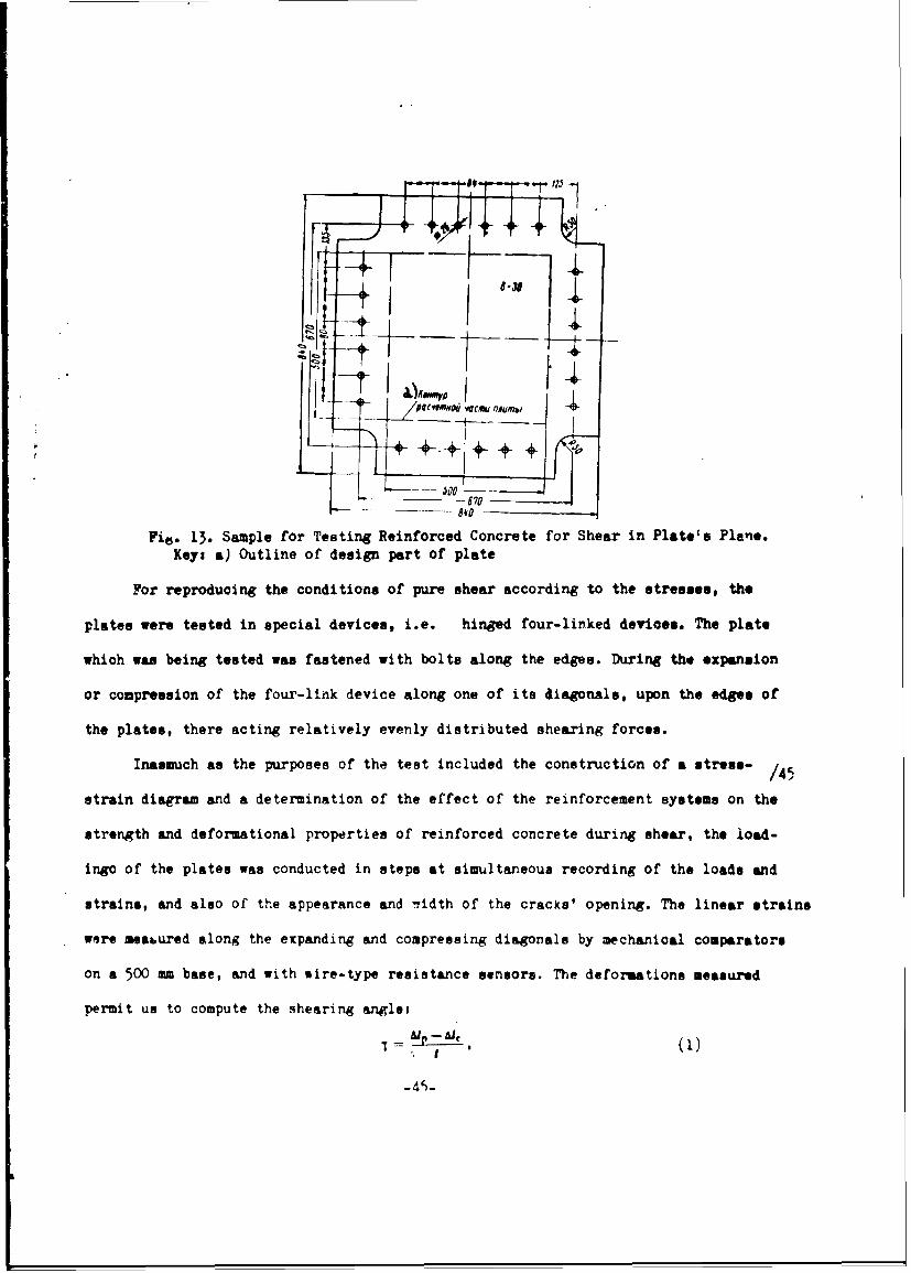
Fig. 13. Sample for Testing Reinforced Concrete for Shear in Plate's Plane.Key: a) Outline of design part of plate
For reproducing the conditions of pure shear according to the stresses, the
plates were tested in special devices, i.e. hinged four-linked devices. The plate
which was being tested was fastened with bolts along the edges. During the expansion
or compression of the four-link device along one of its diagonals, upon the edge. of
the plates, there acting relatively evenly distributed shearing forces.
Inasmuch as the purposes of the test included the construction of a stress- /45
strain diagram and a determination of the effect of the reinforcement systems on the
strength and deformational properties of reinforced concrete during shear, the load-
ingo of the plates was conducted in steps at simultaneous recording of the loads and
strains, and also of the appearance and 7idth of the cracks' opening. The linear strains
were meabured along the expanding and compressing diagonals by mechanical comparators
on a 500 mm base, and with sire-type resistance sensors. The deformations measured
permit us to compute the shearing angles
"I = •_•--i).5 . I

r~ tie*!37
"' i~
o4la re I I Ik4- ~
-~ 1L
SICI L.2 f l No.1 .
to "...7 ,.a 52-5 0.
*' *'It JISAS.41*
1.04 M.*
vhex• • Ip L jc " the valuec of varLation~ in boue of measurement of t~e ex~ri~t"i'
4 C
g.M~ coapremsir•g dia~ornais of plate, reup-•otively1 a Ibn - the base of a•auuremnta.
Krnowin• the er.ear e•.gie .' a~nd the force a.p'ied to the four-Iirfl ar-a'•re- /46
m~t ,e oan calculate the sh.ear €>duiuu:
o- '/T" (2)
The ta•-.•,rti&1 stresees cean be co2V.Fate w) th, a;curazy, ade'juate for tho prac-
tioe, fr~ot tha forfa'lsr
wee tefoc z.,~ ~ h .,,,nrr hin of the four-iink devioe; P•- - the
force er4.n1A the four-ltnK devi:. a~or• the dia~on az Lr, established (r.~i~te,,ed;
by the force •et r of tr~e tes~tr4 •c:•ie; a - len~t~h of plate's side; •" Fiatet,
1,hCIT~oI are,, ?c the ares of r. plate inbassof -me Of tt.on.
WAorsresigdigoas f lte r8"C~vII ri hebaeofm~sreens
Kr~wn h hm ýxe &n h oceapidt h OrI~karnp 4sent,~~~~~~ weo- aclt h -erzdlx

Table 10
ChAracter.stics of Reinforced Concrete and Ferroconcrete Plates
During the Impact Tests
ZW. of zat.rsaaS0
A13.. o ain -Iet tconczt or 420 2.5 n0c8 12 Co3,78A L- 10 400 2.5 5 0. 12 4 , 41
X( 5-2.5 675lo0c
Fo(rro*3 mcrtt 4 70 3 2 t4.)4(6-5 405 5 6 84 9.76
Table 61e Data on Imrf ct Strength or Reinforced Concrete and
Ferroconrete Pltece
a Valne of e.Hpaa ndIn Pdg a o--f C enl 01 a,"'--no"w est If at • for foriveande 'PIS"Ine of a0" ,le f I rot 0Ij•I 8"606 5 anth cek
S Aul.i 8 79) 53
A11i-8 18 000 10)9, )K -256 750 41
)K G-3 7 750 47,*5-5 16 50 t0 10
t¢/,,.t
Fig. ~~i 14 Sha Diga fo Renocd C !cee a- reaiosp + •-'RnCO•,• -• Of In ta _--~ mo u u of reinforced ,,,•,to n a .. dee.d
- " " : " iiic rei--orcement surface.
aln th ,--adin diaona of eapl "K ) el f

The results of testinp the reinforced concrete for shear in the plate's
plane were represented in the form of a functional relationship of the stresses
and strains in a system of rectangular coordinates, where on the y-axis we nave
plotted the tangential stresses I, while on the x-axis, we have shown the shear
angle, X.
In Fig. 14, a, we have shown a shear diagram for reinforced concrete.
The shear diagram is depicted by the segments of straight lines, drawn at a
certain angle to each other. The shear modulus was calculated from Eq. (2)
separately for each sector of the diagram.
The rupture of the reinforced concrete plates during shear took place
by way of the formation and subsequent opening of cracks, perpendicular to
the expanding diaponal. The tests conducted demonstrated that during shear,
reinforced concrete behaves as an anisotropic material. The resemblance con-
sists In the fact that to the pure shear based on the strains, the pure shea.-
based on stresses does not correspond. "Deformation anisotropy" to caused by
the fact that in the plate structural changes occur, heterogeneous in various
directionse as a result of the fact that the strength limit of reinforced con-
crete during stretching (expansion) is considerably lower than its strength
limit during compression, a breakdown of the continuity of the concrete takes
place along the sections, perperdicular to the expanding diagonal; howover, no
cracks form perpendicular to the co'ipressin• (contract'ng) diagonal. Since the
direction of crack formation Is not prescribed In advance, but is determined
entirely by the 6eformatior per se, anl apparent anislropv develops. In this
connection, it is postulated that during the entire loadirR process, the prin-
cipal strain axes maintain their direction. If at sort* stage of the load, the
principal axes alter their direction considerably as compared vitt the previous
stages, the deformation-type anistropy In the previous stages of load In relation

to the subsequent stages viii no longer be the apparent, but viii constitute
the actual anistropy.
In Table 9, we have presented the results of the tests conducted on
reinforced-concrete plates having functioned under conditions of pure shear.
The arithmetic means of the appropriate values have been computed based on
the results of tests made on three plates. The data In Table 9 provide evi-
dence that the Initial shear modulus of reinforced concrete Is connected lin-
early with the value of the specific surface of the mesh wires, oriented In
the direction of the expanding diagonal of the plate (Fig. 14, b). As con-
cerns the values of the shear modulus in the vector after the truncation of
the diagramp for all the plates, It provcj to be practically the same.
The utilization of plates for reinforcement along with the fiber meshes
of an Intermediate welded grating made of rods 5 mm In diameter reduces the
value of the tangential stresses 11 P , corresponding to the width of cracks'
opening 0.005.0.01 mm, as a rule developing in the sections where the trans-
verse rod-type reinforcernt was located. It should be commented that the ap-
pearance of individual cracks of the indicated opening width does not iWrdia-
tely cause a change in the nature of deformation# i.e. the value of the shear
modulus does -ot change at once after the appearance of the first visible cracks. /4,
The truncation of the diagram takes place at the strain li, to which there cor-
responds not the indivicual, but the fairly thickly arranged visible cracks,
In which the opening width remained practically constanc within the limits of
0.005-.001 MM.
After the tMoncation of the diagrams, the Increment in the deformations
In the dirqction of the expanding diagonal tak*s place chiefly owin" to the In-
crease In the width of the opening of the cracks which have formed. The values
presented In Table 9 for the tangent:Al stresses %2 corresposid to the width of
-49-

cracks' opening of the order of •.l1 mm, i.e. to the movnt when we have a
disruption in the nature of the stable deformation of the plates.
A comparisoný %f the values of the initial modulus and of the critical
resistance of reinforced concrete to shear during parallel and diagonal, systems
of plates' reinforcement permits u3 to note that the values of G, and Tj for
the parallel reinforcing system proved to be the highest. This is explained
by the fact that in the parallel system of rein~forcement, the value of the
specific surface of the meshes and of the reinforcerment factor In the direc-
tion of the expanding diagonal is higher than the appropriate values under the
dSagona8 system of reinforcement.
Sdcion 8. nunctioning Capability of Reinforced Concrete During
Impact
In the application of reinforced concrete, as of ferroconcrete in gen-
eral, in the capacity of a hull material for floating facilities, the maximum
interest is represented by the local disruptions from the direct effect of im-
pact: the puncturing of places, the breakage of the watertight sheathing
under a blow, etc.
It is known from the practice that the local breakdow. of a ferrncon-
crete plate under impact depend on the force of the blou and the plate thick-
ness. Ia this connection, on the plate's surface from the side of the blow,
there will appear concentric and radial cracks, while on the opposite side, we
will find cracks, and then cleavages of concrete. Evaluating the effects of
the blow, we proceed from the physical nature of the processes transpiring
under impact and the features of the mechanical properties of the design ma-
terial.
The general thoory of the design for impact !oads has not yet reached
the level when the strength criteria can be clearly formulated, based on the
-50-

analytical relationships hbtween thc strains develo'pinn in the material under
impact, and the deformations. The special studies devoted directly to the
distribution of stresses and strains during the puncturing of a ferroconcrete
plate of limited thickn1ess are completely lacking. Therefore, many private
theories of imoact exist. Several of them shed light on the physical proces-
ses occurring during the breakage of a ferroconcrete plate from the local ef.
fect of a blow./49
In particular, according to the theories assuming for a basis the con-
tact phenomena on the contiguity surface of the colliding bodies, outside of
and on the boundary of the pressure line, the case of pure shear takes place.
Thvrefore, if we take into consideration that the breakdown of concrete and of
materials similar to It under conditions of pure shear based on stresses takes
place from the overcoming of the strength limit of the material under expaz
sion (see Section 7), it turns out that these zones also comprise the most
risky ones in the sense of the disruption of the material's continuity. In
addition, the value of the shear stresses (and by the same token, the time of
appearance of cracks in the materials similar to concrete) is influenced by the
form of the surfaces of the colliding bodies. The greater the radius of the
surface of the body receiving the shock, the higher the value of the shear
stresses which are appearing.
Another unique form of the breakdown of ferroconcrete plates, i.e. the
cleavages (splitting off) is associated with the propagation of the longitudi-
nal waves, caused by the impact. Under the effect of a blow onto a ferrocon-
crete plate, a compression wave propagates inward from the surface at the point
of impact. During the approach to the free surface, it is reflected with the
origination of the expansion wave. At the moment when the incident and reflec-
ted waves do not overlap, and the stresses in the reflected wave reach the
-.51-.

strength limit of the concrete during expansion, the cleavege of the concrete
takes place from the side opposite the impact. The physical aspect of the
cleavage phenomena is particularly complicated when the plate through its
depth consists of seve-al layers. In this case, in the interface of the var-
ious materials, three waves interact: the incident, the reflected and the
forw'ar.
In this manner, the cleavage phenomena comprises a complex aggregation
of breakdowns, caused by the transformation of the com~pression energy into. the
energy of expansion with allowance for the features of the physical-mechanical
properties of concrete, specificallys of the abruptly varying resistivity dur-
ing the deformations of contraction and expansion.
Thus, the existing attempts at a theoretical review of the occurrences
accompanying the local effect of impact testified to the direct connection of
the impact resistance of the ferroconcrete plating with the ability of the con-
crete to resist expansion and pure shear.
Among the dynamic studies, not intended to establish a relationship be-
tween the stresses and strains originating in the material under impact, the
purpose of which is the determination of the relative advantages of the various
materials or of the different types of the same materbal, we include the t sts
of plates with a falling weight. In conformity with the delineated problemu,
the existing diversity in the procedures for conducting such tests precli des
the merited comparison of the results of the tests conducted by various re-
searchers. In our view, the most graphic result* were obtAined by A. A. /50
Kudryavtsev* in a comparison of the impact strength of reinforced concrete and
of ferroconcrete plates. For the comparison standard, he adopted a ferroconcrete
plate 5 cm thick.
*A. A. Kudryavtsev. "On the Question of Impact Strength of Reinforced Concrete &Thin Ferroconcrete Plates," In the collec: "Reinforced Concrete & Reinforced Con-crete Designs", Editorial Board of the Journal "Bulletin of Technical Irtormation"Glavleningradstroy, 1959.
.52.
I

Fig. 15. Design of Reinforced Concrete Plates During Impact Tests.
The ferroconcrete i reinforced conc:-ete plrtes had stiffening ribs
(edges) which served as sulpport for the plate section subjected to impact. The
dimensions of these sections In plan is 90 X 50 cm (Fig. 15). The basic char-
acteristics of the reinforced concrete and ferroconcrete plates are presented
In Table 10. The impact testing of the plates was conducted on a special stand
by dropping a 25 kg weight onto the plate. The form of the Impacting surface
of the weight was spherical with a sphere radius r = 25 ;.m. In the testing
process, we observed the width of the cracks' opening. The evaluation of
the plates' strength was conducted according to the provisional standard of
impact strength ZpHn, equalling the stu;n of products of the weight p times the
height of fall H, and times the number of impacts n from a given height of fall.
The impacts were conducted prior to the development of cleavages, whicth were
adopted for the breakdown of the plates.
The dependence of the opening of cracks In the plates on the value of
the arbitrary standard of impact strength ZpHn prior to the time of appearance
of chipping away of concrete (Fig. 16) Indicates that. the reinforced concrete
plates, its compared with the usual ferroconcrete plates, have an ixicreased re-
sistance to the impact loads.
The combined data concerning %:.e impact strength of reinforced concrete
and ferroconcrete plates are presented in Table 11.
-53-

,oo-- T7 - -
U 0. C.P.• OPJ •420 :25 0,30
Fig. 16. Dependence of the Opening of Cracks in Reinforced Concreteand Ferroconcrete Plates Upon the Value fpHn During the Impact Teats.Keys a) kg/cm, 1, 2, 3- reinforced concrete plates At+ .3, A4.L-5;AL4•8; 4, 5, 6. ferroconcrete plates with a thickness 5.0, 3.0 and2.5 cm.
In the experiments of the authors on the study of the Impact strength
of reinforced concrete and ferroconcrete plates conducted by a similar proced-.
ure (with the sole difference that the weight of the failing load p - 10 kg, /52
while the radius of the impacting sphere r - 15 cm), it was also established
that a concrete reinforced plate 2.5 cm thick, reinforced with 6 no. 10 meshes
of wire 1.0 mm in diameter and with an intermediate welded mesh of rods 5 nm
in diameter has the same impact strength in respect to the cleavages of con-
crete as the ferroconcrete plate 5 cm thick, reinforced with two rod-type meshes,
one of which is formed from rods 8 nmm in diameter with a spacing of 12.5 cm,
while the other Is made of rods 6 mm in diameter with a spacing of 10 cm.
As concerns the quantitative Indexes of the resistance of plates to
puncturing during impact in the tests of such a type, they depend upon many
factors, including the weight of the falling object, the rate of t0e impact,
the geometry of the colliding bodies, etc. Therefore, the quantitative results
of t04 tests of plates by the falling weight, conducted under specific conditi.
ofd, can not be extended to plates with other dimensions or to the case of other
test conditions.
-54.-

The only results having importance which can be obtained from these
experiments consist in a comparison of the nature of the breakdown of the
reinforced concrete and of the ferroconcrete plates, in the qualitative oval.
uat!on of the influence of the systems for reinforcing the platas. At this
level, the available experimental data provide the possibility of concluding
that the dispersed reinforcemnt promotes to a considerAble extent an increase
in the impact strength. As concerns the kinetics of the cleavages occurring
during impact, larger cleavages take place in the ferroconcrete plates. In
the reinforced concrete plates, up to the start of the cleavages, we do not
find disruptions in the continuity of the reinforcement, or discontinuities
in the thin wires of the meshes, but the crushed concrete is held back by
the meshes.
The referenced feature of the breakdown of reinforced concrete plates
during impact as compared with the ferroconcrete plates is significant in the
utilization of reinforced concrete for the plates of marine ( ehip ) sheathing,
since ir this case, the sewpage of water through the damaged places is slight
as compared with the through hulls, and the damages can be repaired fairly
,Imply.
Section 9. Watertightness of Reinforced Concrote
The investigation of the watertightness of reinforced concrete was con-
ducted in plates existing in a stress state under the effect of hydrostatic
pressure. In this connection, the influence of the hydrostatic pressure as a
constant uniformly distributed load on the plate Was prolonged (the holding time
was 40 days).
The tests were conduct-od on special hydraulic stands, on the upper open
part of w, ich we fastened the sample beinE tested (Fig. 17). At the top of the
plate, parallel to its long side, we installca ;., intermrdiate suport, which
divided the plate into two equal parts measuring SO X 315 mm.
-55-

In the process of testing the reinfor-ed concret- plates, we measured
the bucklings (sags) In the center and quadrants of the plates' span and the
external load, and we also observed the nature of the crack formationr with a
measurement of the width of cracks' opening. The required pressure value was
developed by changing the water column by way of moving along a vertical stand
a movable tank with a water-measuring glass, and monitoring wvs also achieved
by observing the sample manometers, installed on each stand.
Fig. 17. EquIpment for the Prolonged Testings of Reinforced Con-
crete Plates by Hydrostatic Pressure.
The loading of the plates was conducted according to the graph (Fig. 18)7
All the plates had the same thickness, 20 un and were reinforced only
by the woven meshes No. 5, 8 and 10 of 8, 12, and 8 layers each respectively
through the entire depth of the sample. Thc specificatiorn of reinforcing the
plates were as follovss
Nesh No. 5 .......... Knw 3.08 cn 2 /cm 3 - 2.79%
Mash No. 8 .......... K n - 3.04 cm,2 /cm3 M•, 2.64-
Mesh No. 10 .......... Kn M 2.28 cm2 /cn 3 $A M 2.86%.
The strength of the concrete to compression at the time of installing
the plates for the tests, established by the testing of control blocks 7 X 7 X 7
cl cU •rised 600-700 kg/cM2.
-56-

6
In an examination of the plates prior to raising thd pressure, we
detected at the corners and along the edge of the clamping frame the cracks
with an opening of 0.05 r•i. These cracks were caused by the squeezing of the
plates' edge during the tightening of the clamping bolts. /54
At an increase in the pressure to 0.6 kg/cm2, we noted the condensation
of moisture on the plates along the edge of finishing and undcr the intermed-
iate support.
At a pressure of 0.8 kg/c.. 2 , when the amount of stresses In the expanded
zone of the section under the intermediate support, determined with the formula
OM H/ V1, equalled 90 kg/cm2 , the plates -sere left under the load.
After a short h)1dIng under the pressure of 0.8 kg/cm2 , on the surface
of the plate in the places where we previously noted the condensation, water
drops appeared. In the course of several days, the intensity of filtration ra-
mained without change, and then it began to decrease and finally toward the end
of the second week of keeping the plates under pressure, the filtration (seep-
age) of water stopped. This can 'e explained by the fact of .he "self-compac-
tion" of cracks, I.e. by the cryctal fo.-Mtion in the cracks on ai base of the
calcium carbonate eroded from the concrete. In the lesser stressed sectors of
the plate between the supports, where under the effect of a prolonged hydro-
static pressure of weter, the opening of the cracks on the expanded surface of
the plates coapi.-ed not less than 0.005 m, no indications of water seepage
appeared.
The nature of the increment of the bucklings of plates In the process
of keeping them for 40 days under the effect of constant hydrostatic ,z-:ssure
Is similar to that described in section 5 for the samples reinforced only bvr
the woven grids (fiber meshes). The difference c:,nsists in th* fact that under
the conditions of constant contact with water, the stabilization of the amount
of sags "akes place In a shorter time (during a half morrh).
.57.

1i
5250 730 c
Fig. 18. Graph Showing the Increase in the Hydrostatic Pressure.Keyi a) q, kg/cf,2 ; b) t, hours.
The tests conducted Indicate that from the viewponint of vatertightness,
of the plating of a hull made of reinforced concrete, the cracks with an open-
Ing ls of 0.05 mm do not present any danger. However, from the standpoint /55
of long life (preserving the reinforcing grids), the presence of cracks with
an opening of 0.05 mm, under which in the Initial period of effect of hydro-
static pressure, the dropwise filtration of water takes place, is not permis-
sible.
These findings are confirmed by the data provided oy other researchers,
particularly the data obtqined in the GIIVT. The GIIVT conducted a study of
the watertightness of reinforced concrete In the flexured sanmples 1000 X 250 X
30 w. From the side of the expanded zone of the samples, a watertight bell
was tightly fastened into which waLer wa" fed under pressure from a tanN.
The stressed state of the samplea corresponded to the arpeararco on the
expanded surface, of crackQ with an opening of 0.01 mm. The pressure was in-
creased in steps. with holding &t each step for 3 hours. As a result, it was
established that the appearance of signs of water seepage (darkenirA of the
compressed lone) takes place at pre sures of around I atm. The dropwise flow
occurred at a pressure of 1.5 atm. The difference in "he values of the pressures
causing the Indications of seepaee In our san1les and in the (I•VT exoeriments.
.5R.

Is explained by the varying stress-strain condition of the sampless ir• our
teats, th6 extent of cracks' opening vat 0.05 ino In tha GI1VT tests, it was
0.01 -.
If we take into consideration that the draft of vessels made of rein-
forced -,ncrete does not exceed 5 m, I.e. the max!imal pressure of water on a
plate in the hull sheathing compries not over 0.5 atm, we can consider that
the full vatcrtightnuss of the ship hulls mad2 of reinforced toncretep even
In the presencG of surface cracko on the plates with an opening o: up 0.01 -,
vill to assured.
H)wever, taking Into account the slight thickness of the protactive layer
of concrete and the intensIvely develeped surface cf ths reinforc~uent of woven
mehes In the reinfor'ned concrete, fot the surfaces contacting the vater, we
should recommend the applicaeton of protective coatings, presenting the pone-
tretion of moisture into the reinforcrd concrete plates, anr thereby protecting
the woven vereera from cor-osion,
fooctIon 10. Resistance of Reinforced Concrete to Freseing
The resistance of reinforced concrete to freazing was studied by coal.
paring the elastic-strength .haracteristics obtained during the testing of
control samples and of samples having passed through 150 cycles of alternate
freesting and thavinS, for pure bending and axial expansion, The control sam-
plas were kept under normal moisture conditions.
The re'nforced samples corresponding to the shipbuilding reinforced
concrete were subjected to the teat*,
Prior tu testing, the samples were Inspected, weighed and placed on It,
4 pieces each In special boxes. The boxe* were placed In a sr.ip, which wa
filled with water at a temprature of +150 C. The submergencke of the samples
"vas achieved to 1/3 of thetr height, In such a condition, the samples were
-59-

kept for 12 hours, whereupon water wes addel to the ship to the level cor-
reeponding to two-thirds of the sample's height, and the samples were again
kept for 12 hours. After the elapsing of 12 hours, the ship containing the
samples was filled with water up to the complete submergence of the samples
(1-2 cm above their upper edge). The samples were kept in such a lZate for
24 hours, whereupon they were again weighed to determine the percentage of
water saturation. Then the samples in the boxes were placed in a refrigera-
tion room and were frozen for 5 hours at a temperature of -170C. The frozen
samples were thawed for 6 hours in waLer at a temperature of +15 0 C. After
each cycle of freezing and thawing, the samples were Inspected.
The samples having passed through 150 cycles of freezing and thawing
were tested for axial expansion and pure bending simultaneously with the con-
trol samples.
It was established as a result of the experiments conducted that after
150 cycles cL alternate freezing and thawing, the reinforced concrete samples
had the same values for the elastic-strength characteristics as the control
samples, having been kept under normal moisture conditions.
-60-

Chapter II. DESIGN OF SHIPS MADE OF REINFORCED CONCRETE
Uetion 11. Most Typical Examples of General Composition /57
of Reinforoed-Concrete gulls
A considerable influence upon the null design of the planned and
built reinforced concrete ships is exerted by the experience of the steel
and ferroconcrete shipbuilding. In the planning of the reinforced concrete
hulls, the greatest popultrity has been gained by the chiefly mixed system of
assembly.
The general requirements for the reinforced concrete hulls of ships
remain about the same as for the ship hulls made of other materials. The main
ones are: operational adaptability, rel4:. ty, technological effectiveness,
and econooy of design at minimal weight. Eowe• er, the design embodiment of these
requirements is affected by the specific featurrs cf reinforced concrete as of a
shipbuilding material iiý general, and as of a variety of ferroconcrete in particular.
Thus, as cnmpared with ordinary ferroconcrete, reinforced concrete is most
suitable for the produ-tion of designs of the shell type. Tne application of
reinforced concrete in place of ferroconcrete introduces a significant simplifi-
cation into the technology of producting the shell designs, specifically it assures
the possibility of the fo-mless preparation of the individual designs and hulls
of ships as a whole. In this manner, preserving all the advantages of ferro-
concrete during its functioning in the composition of the shell-type designs, at
the same time the reinforced concrete permits us to simplify considerably the
technology of manufacturing the shell designs, and hence to reduce their i.nwi6Jdi-
ness mid cost. However, if we are oriented only on the completeness on the
sectional method of the construction cf reinforced concrete sLips, the applica-
tion of the shell-type form of hull proves to be inefficient, since the curvilinear
_61-

outlines of the hull lead to an appreciable (as compared with the flat) compli-
cation 3nd increased coat of the technslcgical equipmint, and to an increase in
the labor end cost of proucing the prefabricated elements and the formation of
the hull on the building slips. /58
Frcm ftat has been said, we can conclude that one of the determinative
conditions of the choice of a shell design of a reinforced concrete hull is the
method of construction.
It is known that the gerieral tendency in ferroconcrete shipbuilding con-
siats in the transition to the completely prefabricated construction method,
guaranteeing (with the eimplified flat outlines of the hull) the industrial pro-
duction of the prefabricated parts of the hulls and ships superstructures.
This tendency has exerted an influence also on the development of the hull design
in reinforced concrete ships. The planners, not taking into account the
specifics of reinforced concrete, have not utilized the possibility of the form-
leos preparation of the hull by the mcnolithic method, and has suggeste as a
basis,the sectional plane design of hulls.
Let us consider the essential design syctems of :einfoiz.ed concrete marine
hulls based on the results of the plat-ing design studies, and alto of ships
already built.
Reinfo--oed Conoreto Ships with Ruils Made in the Form of Circular Unframd
Cylindrical Shells. An example of such hulls is represented by the planning studies
of the barge-platforms with a hoi0tirf JaPacitj uf 600 tnxis (Fig. 19) and of a
platform with a length of 20 m (Pig. 20). For the indicated hulls, it is typical
that in them the basic support element is the reinforced concrete shell, not
supported by beams of the set. The strength and stability of the reinforced con-
crete shells is provided by 'their spatial-curvilinear fcrm.
The reinfor(.ed concrete circular cylindrical ishe:ls are interconnected
-62-

into A unified hull by transverse bulkheads and ')y a deck also made of reinforced
concrete. The hull shells of the barge-platform have along the bottom and on
the deck supports in a longitudinal direction in the form of reinforcin rods of
large diameter for receiving the forces from the overall longitudinal bending.
If we analyze, even if only in general outlines, the operating and tech-
nological qualities of the reinforced concrete lulls made in the form of circular
cylindrical shells, we can notice that:
- the nulls have a small coefficient of completeness, and hence a high
draft and a large wetting surface as compared with the flat-deck hulls;
- the conditions for utilizing the hatches in the hulls under the various
rooms and for the placing of cargos in them prove to be less favorable than in the
flat-deck hulls; and
- the construction of hulls both by the prefabricated and by the monolithic
method in the absence of mechanized production of the circular cylinders 4s quite
complex.
At the same time, a circular cylindrical shell is the most improved form
from Vie viewpoint of utilizing the elastic-strength properties of reinforced con-
crets.
Therefore, in the case of the develrpment of the technique of the mechanized
production of circular reinforced concrete cylinders during their mass output,
these cylinders can be utilized effectively for the formation from them of hulls
of such floating facilities, on which the installation of the cargo and service
qu.rtere is done outside of the hull (barge platforms, pontoonai etc.), and the
travel speed is slow.
Reinforoed Concrete Unformed Hulls in the Form of Simplified Shells. In
÷hiir configuration, the lines of such ships are close to the lines of the mono-
typical metallic and plastic vessels. The basic support element of the hull is
-63-

as
900 - 7000--000 1 7000 7000 -7000
6)000
pig. 19. Barge-Platform Made of Reinforced Concrete: a- section along
DP; b- plan of barge with deck covering removed; c - transverse/60
section.
the reinforced concrete shell, not supported by beams.
Fig. 20. Cross section of Reinforced concrete hull of a platform of
shell-type design.
The conditions of the operational adaptability and hydromechanical qualities
of the ship are easily assured under the combination of the curvilinear and flat
surfaces of the hull. However, the unframed type of hulls can be made only for
small snips of the lifeboat type, surface and excursion cutters, etc, experiencing
-64-
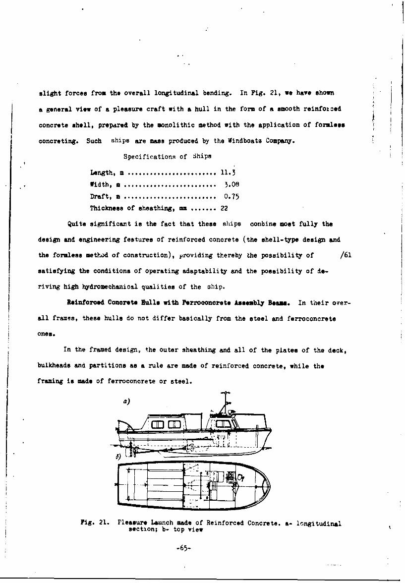
slight forces from the overall longitudinal bending. In Fig. 21, we have shown
a general view of a pleasure craft with a hull in the form of a smooth reinfoi-ed
concrete shell, prepared by the monolithic method with the application of formless
concreting. Such ships are mass produced by the Windboats Company.
Specifications of Ships
Length, m ................ i.
Width, m 0........ ... ....... 3.08
Draft, 2 .* ......... ......... 0.75
Thickness of sheathing, m ....... 22
Quite significant is the fact that these ships coumbine most fully the
design and engineering features of reinforced concrete (the shell-type design and
the formless method of construction), providing thereby the possibility of /61
satisfying the conditions of operating adaptability and the possibility of de-
riving high hydromechanical qualities of the ahip.
Reinforced Concrete Hulls with Ferroconcrete A•sembly Beams,. In their over-
all frames, these hulls do not differ basically from the steel and ferroconcrete
ones.
In the framed design, the outer sheathing and all of the plates of the deck,
bulkheads and partitions as a rule are made of reinforced concrete, while the
framing is made of ferroconcrete or steel.
a)
-- ~A Ob.-bx¶ J
---------
Fig. 21. Pleasure Launch made of Reinforced Concrete. a- longitudinalsection; b- top view
-65-

The hulls of the planned or built framed reinforced concrete ships have
a transverse or combined system of framing.
The outlines of the framed hulls can be the mold type or simplified, deje:,d-
ing on the purpose of the ship and 'Vhe method of its construction. In case of
orientation on the fully framed methoc of constructiun, the most effective in re-
spect to labor and cost of construction, especially on a large scale, are the
simplified configurations (flat sides, oottom and transom ends). However, there
are no bases for giving preference for the framing method of constryirtinn, if the
simplification of the lines leads to a considerable depreciation of the hydromechani-
cal qualities of the ship. For the construction of the frame-type hulls of mold
(template) outlines, we can apply successklly the monolithic method, with the
utilization of the formless concreting, which, not requiring high skill in the
workers or expensive equipment, can easily be mastered by any shipyerd. /62
Thus, in the template outlines of a hull, we sh'uld use the formless mono-
lithic method, especially in the individual construction of ships (or in small
batches).
In Fig. 22, we have shown a cargo ship of framing design, of template
lines with a c!rgo capacity of 100-120 tons. The system of framing the hull along
the bottom is longitudinal, and along the sides and deck it is transverse. With
five transverse watertight bulkheads, the hull is divided into six compartments.
The depth of the reinforced concrete plates of the sheathing in 25 mm. The framing
beam ( 150 - 350) X (40 - 60) m • -ade of ordinary ferroconcrete. The frame
spacing is 700 M, and the distance between the frames under the longitudinal system-
of framing the bottom equals 1400 m.
An example of a Phip with a hull and superstructure made of reinforced
concrete, having simplified outlines in combination with the template ones, can
be provided by the driftwood hoisting crane with a cargo capcity of 10 toni
(Fig. 23).
-66-

Specifications of Floating Crane
L. ength, m ................. ** 24
Width, m ....................... 10.4
Molded depth, m ................ 2.2
Framing system of hull transverse
Amount of spacing, mm .......... 700
Thic ness of sheathing, mm ..... 25
In the stern part of the hull, in the region of frames 19-33, we have
a slot 5.8 m long, the continuation of which is provided by a tunnel passing
into the bow counter. The bow and stern of a sled type are raised.
The hull has two longitudinal and seven transverse bulkheads. The longi-
tudinal bulkheads are a continuation of the internal sides of the recess (slot).
The design thickness of the reinforced concrete sheathing of the bottom,
sides and deck is 25 mm; that of the longitudinal and transverse bulkheads is
20 mm; and that of the transoms is 30 mm. The framing beams with a cross section
(100-200) X (40-50) mm are made of ordina-y ferroconcrete.
The method of building the hull and the superstructure is entirely pre-
fabricated. In this operation, the individual sectional elements are ribbed
designs, i.e. reinforced concrete plates, fastened by the ferroconcrete framing
beams, made on a base of cement-sandy concrete. The production of the pre-
fabricated parts was conducted on the bottom plates with the ribs upward.
For reinforcing the sheathing plates of the hull, we used six
pieces of woven mesh, No. 10 based on GOST 3826-47, an intermediate rod-type
mesh with a reinforcement diameter of 4 mm according to COST 3292-46. For
reinforcing the framing beams, the reinforcement diameter was 6 and 10 =
based on COST 380-60 and the reinforcement of periodic profile with diameter of 16
and 20 mm,grade 35 GS based on COST 5059-57.
-67-

0- 9R
560
IIt
.. •P-P•4-11't-1. tH• -H -fHHr-PIHV - Hrtuk*2000
Fig. 22. Diagram of Hull Framing of Dry-cargo Steamer with a /63
Cargo Capacity of 130-120 tonat &- section according to
freight agreement; b - layout of deck; and a I layout
of bow.
664
SIT
-i+-t---F-4. I--F •-+ -I--4 • --F--I--4- --- - i-• - t- F-' -- -- l---- -•* -l
I- 1 ~ ! I ,1 i ll,
r - vro'
x, I I i I ri i I_ ' 1
g~ ED9i*n -- - ' .'. -! ' --t , - -i- -
L 4
SI I
9 I I I I I I
I I, I
"-.• -,-•-• . ... .' ' ' -- J ... . . - ,-,..., :.• .,- -.,- --" ,1
r ' i |( I t , • ii I . . . i t ., i, -i•
,•-T I'!-'• +" -•1-' -•-' -• . .. . • _ ._ | " -i .-

On o 2•,# "00 00 0 1 .JO-- 00-----..-----• .----- 5•00 -- i 70--
L -1- - -v --I l I
J37 ?3 •.17 ~7 , :• ' 2 s9.0' O5 hiJj -&~ l- FSLIJ 32 JI 30 '91 It 77 26 9• ?4 1' '2 •
Fig. 21. Design Drawing of a Hull of a Floating Crane:
a - section according to freight agreement; b - layoutof deck; c - layout of bow
/66
-VA0'
a2 CrgCpait L-_-' -. Tons
I.
--_-_ ___FT-
Figl. 24. The Midship rae• ,f" a Barge Platform .it•,
£ aro apc-y69-on

- -- ; A -A
S- - tr o l .i
-i ,.j - J
_4i
ci m4q • / ---
Q4
+i , +. . . . . .. . v . . ' - -- -- --E
-- % A P .... ... . ) I - -" J o tA A
* - " ie..... illl~ - -- i -, ...! .* .*"L.;A I tL L | i'.. ill.Lill * .iLL L~
IIIF,,-L + I±m-
-100
#41 p r... ..
!', "-"
k A-4 .... '
M,
- 444Maitl; Yuri *1.
P l• 2 5 C r s s e c t i o o f h u l o f m r n e s l w t h l v r a d m d l
-70-I
f l ,•_•-+L.?7flj,4 WI
'' if r III
SO " f gi iVli 4 lj . _i_ _
" I. +.+' __,_.____,,
P+ig. 2*5. Cosscio fhl of/aerine "msl wihlwran ii.i ". ',,ii-t!docks;" mae o -ir r e c n r t... i• ttJ
i • • .- • --.--- -+P L,/ ., i.. .. .li -.....-
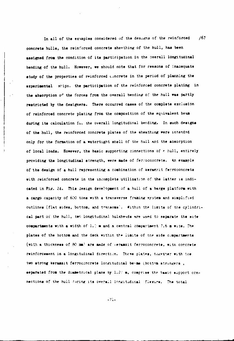
In all of the ex'iamples considered of the designs of the reinforced /67
concrete hulls, the reinforced concrete shepthing of the hull, has been
assigned from the condition of its participation in the overall longitudinal
bending of the hull. However, we should note that for reasons of tnaiequate
study of the properties of reinforced •.ncrete in the period of planning the
experimental srips. the participation of the reinforced concrete plating in
the absorption o' the forces from the overall bending of the hull was partly
restricted by the designers. There occurred cases of the complete exclusion
of reinforced concrete plating from the composition of the eqtivalent bel.
during its calculation fo& the overall longitudinal bending. In such designs
of the hull, the reinforced concrete plates of the sheathing were intendsd
only for the formation of a watertight shell of the hull ond the aosorption
of local loads. However, the basic supporting connections of - hull, entirely
providing the longitudinal strength, were made of ferroconcrete. An example
of the design of a hull representing a combination of kerar.7it ferroconcrete
with reinforced concrete in the incomplete utilization of the latter is indi-
cated in Fig. 24. This design deve.opient of a hull of a barge platform with
a cargo capacity of 6CC tons with a transverse frfming sy3tem and simpl'.fied
outlines (flat sides, bottom, and t-ar.soms'ý. within thp limits of the cylindri-
cal part of the hull, twr. longitudinal bulkheids are used to separate the axie
compartments with a width of 1.7 m and a central copatenr.t 7.6 a w~ie. The
plates of the bottom and the deck within tto limits of tr.ne side cjupartments
(with a thickness of 860 mmý are made of ,eraaxit ferroconcrete, witn corcrete
reinforcement in a longitudinal direction. Thcge plates, topetlier with ',he
two strong keraazit ferroconcrete longitudinal be,-ae kbottom stringers
separated from the diametrical plane by 1.2/ a, coamrise the basic 9,p;ort ccn-
nections of the hull ýiring its overal loroitudinral f lure. The total
-71-

- /68
N, I IL
Qi
• .rx. .. -.?.----------.--l-l-. - - .,. , • ", -*!
1 J.
- ...... ..U .. - ~M a k* ~ 4 r:,t 2"
... .. ... .. .. ...... ....-- #*..**.- "• 'P" -
"1 r-, -- • , '1. . . . : , : - - , " - . " '; - -
Fig. 26. Rargc with cargo capacity of 1000 tons made of reinforcedconcretes a - arrangement of sections in case of coupling; b - viewof bow part; c - side viev of one of vections; d - plan and secttonalcn. ABCD of one of the sections.
-72-

transverse strength of the barge hull is provided for fairly strong frames,
formed by the beams and reinforced bottom frames, and also by the transverse
watertight bulkheads, also made of the keramzit ferroconcrete.
The reinforced concrete is used for the plates in the bottom sheathing
%ithin the limits of the center compartment, th,! side sheathing and the longi-
tudinal bulkheads. The depth of the reinforced concrete plates along the side
and bottom is 30 mm and along the longitudinal bulkheads, it is 25 mm.
It is natural that such a design of the hull has an excess of strength,
and is given here only as an illustration of the unjustified combination of
reinforced concrete with ferroconcrete in the composition of marine hulls. Under
similar combinations, the reinforced concrete should be taken into account in
the calculations of the overall hull strength.
The combination of reinforced =oncrete with ferroconcrete is aLso
possible in the completel:" ferroconcrete hulls, where the reinforced concrete
can be applied for the production of bulkheads, partitions, platforms and
'tweendecks, which allowed us to reduce the weight of the ferroconcrete hulls.
The feasibility of such a combination should be determined with allowance /70
for the production possibilities and the experience of the shipyards in the
production of reinforced concrete designs, and also the effect from reducing
the hull weight, obtained during the replacement of its individual ferroconcrete
designs by the reinforced concrete ones.
Thus, in one of the planning Atudies of the ferroconcrete hull in a
marine ship for purposes of reducing the ship weight to a value assuring
its ability to navigate through the internal waterways, the 'tweendeck of
the hull was planned to be made of reinforced concrete (Fig. 25). However,
in view of the fact that the shipyard builder of this sLip did not have ex-
perience in producing the reinforced concrete designs and lacked the appropriate

technological equipment, it was considered more economical to make the deck of
keramzit ferroconcrete; the production of ship designs from this material had
already been mastered by the shipyards, and in its utilization for the 'tweendeck,
the required reduction in hull reight had been achieved.
Reinforced Concrete Hulas with Fratming in the Form of Flat Reinforced
Concrete Weabranes. Such a system of framing is also finding application in the
bulls made of standard ferroconcrete for ships of small dimensions (for instance,
for floating docks 20 m in length ).
The hull of the barge platform, of which we spoke previously, has along
with the beam framing, the transverse keramzit ferroconcrete membranes in the
inter-side space,situated along the frames. As a result of this, the hull within
the limits of the cylindric&,. insert is divided into 38 small side and one central
(large) watertight compartments, by which we provide the operating reliability of
the barge. For the given barge, in a number of cases, there can be permitted
the simultaneous flooding of up to 10 non-adjacent side compartments without
risk of losing buoyancy stability or strength of the hull. The framing system
ia the form of flat membranes in a pure form, i.e. in the absence of any framing
beam in the hull makeup, was adopted in the dry-cargo towed barge, built in
Czechoslovakia, with a cargo capacity of 1000 tons (Figs. 26 and 27).
Basic Characteristics of Barge
Length, m . . . .. . . . . . . . . . (*8WNidth, m .. .. .. .. ...... 9.6
Molded depth, m . . . . . . . .... 2.4
Sheathing thickness, ma ........ 30
The barge hull consists of two identically designed hinge-jointed sections
with a length of 34 m each.
The lines of the barge hull are simplified and flat. The transom ends are
formed by a rise in the flat bottom and the plane sides, with a division into six
-74-

transverse sections.
Within the limits of the cargo holde, the hull has a double bottom and
double sides, in the space between which are installed the flat longitudinal and
transverse membranes (diaphragms). The sheathing of the bottom, sides, second
bottom and membranes is made of reinforced concrete 30 mm thick, reinforced by
4 steel gratings of wire 10 mm in diameter, with screen meshes 4 X 4 mm inside
size. Along with the finely-meshed screens for reinforcing the plates, and also
for supporting the bilge reinforcements and the deck stringer, %e use the rod-type
reinforcement installed in the center of the plates' depth, between the thin
screens. The amount of spacing equal 1200 mm; the distance between the longi-
tudinal ties (membranes) along the bottom is 800 mm.
Vo GUo_ _*.__,o
J600
Fig. 27. Design Midship Frame of a Barge Made of Reinforced Concrete.
The method of building tlhe barge hull is sectional-monolithic. The trans-
verse and longitudinal connections (flat membranes) and also the ends of the
barge were made separately ann delivered to the slipway in the form of finished
flat and three-dimensional sections. The preparatior of the bottom, the flooring
of the second bottom, of the outer and inner 3ides was achieved directly on the
slipway by the monolithic method with the utilization of formless concreting.
We should remark that the baige, in distinction from the above-considered reinforced
concrete vessels of framing design is completely made of reinforced concrete,
including the framing. An this connection, the engineering and design poten-
tialities of reinforced concrete as a 3hipbullding material were employed mostcompletely and advantageously in the given design.
-75-

Thus, the internal parts of the hull (diaphragms, floors, stringers)
represent flat prefabricated (sectional) reinforced concrete designs; the tech-
nology of their production is much simpler than that of ribbed plates, consis-
ting of a reinforced concrete strip and of ferroconcrete ribs. From such pre-
fabricated designs, we can assemble the three-dimensional sections and deliver
them to the slipway.
The division of the barge hull into two hinge-jointed sections creates
the conditions under which we reduce appreciably the expanding (stretching)
fu.. f " the overall lonjitudinal flexure, which is quite important for /72
reinforced concrete having a relatively low permissible stress for expansion,
which essentially limits the dimensions and cargo capacity of the reinforced
concrete vessels. It is evident that such design measures will also be useful
in the development of reinforced concrete barges of large cargo capacity, at
the same time facilitating the expansion of the range of efficient utilization
of reinforced concrete in shipbuilding.
The production of the cylindrical part of the hull directly on the slipway
by the monolithic method with the use of a formless concreting should also be
regarded as a technically and economically justified solution, in spite of the
general tendency of ferroconcrete shipbuilding toward the completely prefabricated
construction method. It appears that the formless meth-od of building the
reinforced hulls, since it significantly raises the technical-economic indexes
of the monolithic method of construction, should find that broad application in
the building of ships of reinforced concrete, especially prior to the development
of highly-productive equipment for the preparation of prefabricated marine
reinforced concrete designs, and the finding of more simple and technolopically
efficient intersectional connections.
-76-

Section 12. Design of Marine Reinforced Concrete Plates.
A basic element of the reinforced concrete hulls and superstructures of
gtJips is the design consisting of plates reinforced by the framing. In this con-
nection, the plates are the reinforced concrete itself in the composition of
the hull, whereas the framing beams are made chiefly of ferroconcrete. The total
weight of the plates in the composition of the hull comprises more than Yulf the
•! hull weight.
The reinforced concrete plates in use as hull sheathing can be flat or
curvilinear, while depending on the hull design, they can be riblees or with a
framing. In their purpose in the makeup of the hull, th÷ plates are s-pported
by ribs, running only in one direction or mutually intersecting (Fig. 28).
A A
4- -
- I
B.-_ - k _ - . . .•
Fig. 28. Reinforced concrete plates with ferroconcrete ribs,a - arrangement of ribs in one direction; b - arrangementof ribs in two directions.
The plates in use for ,' iheads, and partitions in the hull and super-
structure and also for the • ill panels and co-ers of the superstructure can be
spatial reinforced concrete elements of the shell or fold (convolution) type.
-77-

The thickness of the reinforced concrete plates of the hull sheathing,
as the ferroconcrete ones is determined from the condition of adequate strength
with the participation of the ship hull in the overall bending and in the absorp-
tion of local loads (the minimal thickness of reinforced concrete plates should
comprise not less than 10 mm, while the maximal should be 50 mm). Depending on
the plates' thickness, their reinforcement can be made as only thin finely-meshed
screens, or as thin screens in combination with the usual reinforcement in the
form of rods or of rod-type screens, located in the central part of the plate's
section height. /73
It is recommended that the plates with a thickness of 10 - 15 m- be rein-
forced only with thin woven or welded screens.
For the plates thicker than 20 mm, basically we apply the combined reinforce-
sent (the thin screens in combination with the rod reinforcement in the form of
individual rods or welded screens).
The reinforcement of plates and their thickness are determined by strength
calculations and are conducted in accordance with the recommendations discussed
in Chapter I.
The number of layers of woven screens in the reinforced concrete plates,
from the condition of providing the guaranteed quality of the placing and packing
of concrete in the design, is assumed to be not more thant
For plates with a thickness
10 m- ........ 4 layers
15 mm ........ 6 layers
20-30 mm ....... 8 layers
In this connection, for tte plates having a combined reinforcement, from
the side of the expanded zone, we ise not lesz than •-3 thin screens.
The d:ameter of the rod-type reinforcaemnt in the combined strengthenirn
of the plates is established in dependence on the plates thickness, from the
-78-

condition of installing in the plate the required number of woven (fabric) screens,
i.e. the obtainment of the specific reinforcing surface required for the shipbuilding
reinforced concrete, and also for providing a protective concrete layer 2-3 mm
in thickness. Under these conditions, as a rule the diameter of the reinforcing
rod is not more than 5-6 mm.
The number of rods per running meter of intermediate screen is established
by calculation and should correspond to the requirements of the "Rules for
Construction of Ferroconcrete Ships" of the River Register of the RSFSR, according
to which the number of rods in the working direction of the plate (the rods /74
directed parallely to the smaller side of the support edge of the plate) should
be not less than 5 and not more than 20 per running meter of the screen. The
sectional area of the distributing reinforcement in the plates (rods, directed
parallely to the larger side of the plate's support edge) should be not less than
15% of the sectional erea of the working reinforceuent. In this connection, the
distance between the rods, from the condition of standardizing the reinforcing
rods, should be a multiple of 50 mm.
The depth of the protective layer of concrete (independently of the purpose
of the reinforced concrete plates) in the composition of the hull and the super-
structure of the ship falls in the limits of 2-3 mri. The contact of the thin
screens with each other during the fabrication of the reinforcing frames of the
plates can be conducted without lap welding with the overlapping of the ends by
not less than 100 m. In the application of resistance-spot welding, the over-
lapping of the ends is not less than 10 ma. The joints of one layer of screen
should be displacea relative to the jcints of the other layers so that in any
section of an element, there would not be more than one joint. The co'.nutiun of
the rods of the intermediate screens is conducted as in the designs made of ordinary
ferroconc rete.

In distinction from the ferroconcrete plates, as a rule the reinforced
concrete plates have a reinforcment section which is symietrical relative to the
CG (center of gravity). However, in certain instances for increasing the strength
of a plate operating under flexure with an expansion, the expanded zone of the
plate in the working direction is reinforced additionally with rods having a
diameter of not more than 5 mm.
Since the plates of the reinforced concrete hull are calculated as beau-strips,
fitted into the support, where the bending moments are considerably htgher than in
a span, the additional reinforcement by rods can be utilized for complying with the
strength conditions on the support. Owing to this, the plate thickness is reduced
appreciably.
Section 13. Framing Beams
The framing beams of the hulls and superstructures of the ships made of
.einforced concrete can be of ferroconcrete (of the ordinary or prestressed ferro-
concrete) and metal.
The design developuentrj and the experimental studies on establishing the
possibility and feasibility of applying the framing beams of reinforced concrete
(with combined reinforcement, and reinforced only by woven screens) have shown
that the introduction of woven screens into the plate ribs complicqtes greatly the
procedure in producing the ribbed design and does not guarantee their quality. In
connection with this, the framing beqms amade of reinforced concrete have in effect
not found application. /75
The simplest from an engineering standpoint are the framing beams made of
ordinary ferrocuncrete, which have also found wide acceptance in the construction
of reinforced concrete hulls. In the fabrication of the ribbed reinforced concrete
plates, the ferroconcrete framing beams are concreted with cement-sandy concrete
of the same composition. Under the sepairate technology of fabricating the plates

and r.0, it is also possible to have the concreting of the ribs by keranzit
concrete in order to reduce the weight of thi designs.
7J-305/•pe @'1 -
Fig. 29. Configuration of cross section of ferroconcrete beamstrengthened by reinforced concrete plates: a- in the fabricationof the designs with beams upwsrd; b - in the fabrication ofdesigns with the beams downward.
The configuration of the cross section of ferroconcrete framing beams
depends on the technique of fabricating the ribbed designs of the plates. In
the production c.1 the plates with ribs upward, the cross section of the ribs is
a rectangle (Fig. 29, a); in the production of plates with ribs downward, in
the nondetachable form-matrices, the lateral surfaces of the framing beams havi
a slope ranging from 1:10 to 1:15 depending on the beam height (Pig. 29, b).
The dimensions of the framin beams and their reinforcement are established
from the conditions of providing the Rtrerngth, minimal weight and technological
effectiveness of the designs. The approximate sizes of the framing beams are
adopted in the following multiple of the dependence on the thickness of rein-
forced concrete plate: with 2 - 2.5; height 5 - 8.
As a rule, the ferroconcrete framing beams have chamfers in the places
of attachment to the plate, with a cathtus value of 25-•0 rmm.
It is recommended that the reinforcement of the beams be acconplished
in the form of flat or three-dimensional welded frames. "he diameter of the
working reinforcement of the beam is not less than 6 -m, while the inside dis-
tance between the reinforcing rods in one directiorn be not Aess tan 5 mm.
The clamps are made from reinforcing rod with a dsaoeter ranging from
4 t•c 6 - according to the diameters of the intermediate rod reinforcement
-81-

in the reinforced concrete plate. The distance between the clamps equals the
distance tetwecn the rods of the intermediate plate reinforcement, installed
perpendicularly to the beam's axis. /76
The thickness of the protective concrete layer of the framing beams
wmasured from the outer iurface of the clamps to the outer beam surface in not
leos than 5 sm.ý0 60
Fig. 30. Systems of Reinforcing the Ferroconcrete Framing Beansof Reinforced Concrete Designs Keyi a) 3 layers of woven screen.
The cross sectional area of the working beam rods is established by the
strength calculations, and the number of rods is also found based on the condi-
tions of their instailaltion in the beam, i.e. by the dimensions of its cross
section. Thus, the beass of small sizes (ro X 150 sm) as a rule have in the
lower and upper part one working rod each of aoout the same diameters (Fig.50).
ftr the beams of larger dimensions (60 X 250 mm), the number of rods in one row
along the horizontal is Jouoled, au.d when neoess.ry, in the upper part of the
beas, the rods are installed in two rovs (see Fig. W0). With such a number of
rods, it is quite important to maintain between them along the vertical and
horizontal an interval required for providing the combined operation of the
reintcrcement with the concrete.
The observance of the incicated spacings in the units of the TInt4raection
of beam of different direction is practically Impossible, therefore 'In the
intersection points, the requirement concerning the preservation of the standard

spaces between the rods is extended only to tne rode running parallely; as a
rule, the intersecting rode come into contact (Fig. 31).
The connection of the framing beam with the reinforced concrete plate
should be realized by way of diverting the bent parts of all clamps of the beam
between the woven screens (in the reinforcement of plate., only with 'oven screens)
or beyond the intermediate rod-type screens (in case of the combined reinforce-
ment of plates). The length of the clamp folds anchored in the plat6 is not
loes than 15-20 diameters of the clamp. /77
Such a design of connecting the reinforced concrete plates with the
ferroconcrete framing beams was verified during the testing of beams with a con-
nected strip for bending. All of the beams broke along the oblique cracks without
a shifting of the plate relative to the beams, which confirms the reliability
of the connectir4 system adopted.
Fig. 31. I e F n o- .
Conret Neeg
!
:_:__:_ 1 -c
!.-
Fig. •1. Interseeting Ferroczoncrete Frauing Rerns of ReinforcedConc re.t D~esign
-Fa S-

The connection of the fittini;s of the ferroconcrete beams
along the length, and the construction of the intersections of
beams in varying direction are conducted in conformity with the
instructions of the "Pules for .ve Constructioi, of' Ferroconcrete
Ships" of the River Registry of the RSFSR by analogy with the
designs made of standard ferroconcrete.
For purposes of reducing the difficulty in producing the
hulls and superstructures of ships from reinforced concrete, it
Is necessary to strive toward the maximally possible standardiza-
tion of the dimensions and reinforcement of the frame beams. /78
Section 14. Intersectional Joints
The application of the prefabricated method of building ships
of reinforced concrete involves the necessity of connecting the
sections or units during the assembly of the ship on the slip-
ways. These intersectional Joints have their unique features.
Connections in one plane. The major part of the intersec-
tional Joints cccur in the hull plating.
The main requirements which the cunnections of tne sheathing
plates of the reiniorced concrete hulls must meet include the
provision of strength, watertightness and technological effective-
ness. The primary type ,,f connecting thi sheathing plate in one
plane is the connection in the outlets with a bypass of the ends
(extruding from each section) of the fiber-type ard rod-type
intermediate grids.
Depending on the type of load on the design, the connectio)ns
of the plates on the outlets -ran be made without welding or with
welding.

The weldless Joining of the plates is used only for the
designs operating on contraction of flexure. In this case, the
value of the by-pass of the fiber grids is not less than 50 mm,
while the size of the by-pass of the intermediate rods is not less
than 20 diameters of the rods (Fig. 32).
=) 1 00- n
250-
8, 50 _ 0 50
A-A| 100 ,_ 50 , n 1- , 0
"•" •" •. 300 .
Fig. 32. Examples of the Connection of ReinforcedConcrete Plates with a Thickness of 10-15 mm for theBy-pass cf the Webbed Screens During Reinforcement:a-with three; b- with two; c-with six; and d-withfour webbed screens.
The connections of the plates on the outles for the designs
operating on axial and eccentric extension, are made with the weld-
ing of the by-passes of the webbed screens and of the intermediate
rods. The amount of the by-pass of the webbed screens in case of
their Joining by resistance spot welding is not less than 20-30 mm,
wh~le the by-pass of the intermedipte rods (and the length of the
welded joint of the rods) is not less than 1i diameters of the rod
(Fig. 33).
-85-
I 1 ! ! ' I , [ ,

I
*- O U - ----S•10
L. 70 350
g o- - -. ---' -
_•.,,.- JL i- - -
Si 00 0 . .
Fig. 33. Examples of Joining the Reinforced Conc ete Plateswith a Thickness of 20 - 30 mm in the Welding of Cutletsduring Reinforcement: a - with four; b- with six- c- witheight webbed screens and intermediate rod-type screen.
Key: l)welding in at atmosphere of CO 2 .
In both cases, the joining of the webbed screens (both with
welding and without welding) is done in order that there would by-pass
flush all the screens, and in each section there would not be more
than two joints of the screens.
The types cf connections shown in Figs. 32 and 33 a-e
equivalent wi±h the monolithic type in strength and crack resistance,
since the structure of the reinforcement does not disrupt in the
joints, which has been confirmed by spezially conducted tests.
However, the connections of such a typ!: are laborious in preparation,
in view of the largt volume of rigging and welding •t ~vity. and
also the complexity of making the loint monolithic, 2specially in

a vertical position.
In spite of the indicated technological disadvantages of this
connection, it should be applied for the outer sheathing of the hull,
since the crack resistance, and hence the watertightness and the
corrosion strength of the joint are equivalent to that of the mono-
lithic type.
The connection which is most technologic&lly simple is ttle
joining of plates including the welding of the by-pass intermediate
rods,but without by-passing in the zone of connecting the fine net-
works (screens)(Fig. 34).
0 1
Fig. 34. Connection of Reinforced Concrete Platenwith Welding of the Outlets. Key: a)per runningmeter; b) six meshes N 8-0.7
For providing equal strength of the joint with that of the /82
monolithic type, In the plates along their edge during the prepara-
tion, we install additional rod-type fittings, the diameter and
number of which are established by calculations. The additional
rod-type fittings are anchored in the prefabricated designs for a
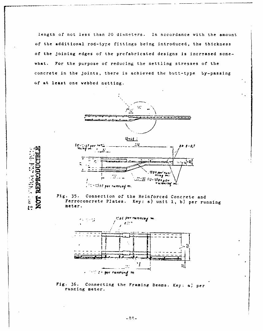
length of not less than 20 diameters. In accordance with the amount
of the additional rod-type fittings being introduced, the thickness
of the Joining edges of the prefabricated designs is increased some-
what. For the purpose of reducing the settling stresses of the
concrete in the Joints, there is achieved the butt-type by-passing
of at least one webbed netting.
Sd P" I n.... -
=1 -- -. 7A
Fig. 35. Connection of the Reinforced Concrete andFerroconcrete Plates. Key: a) unit 1, b) per running
•- Zmeter.
/ a-.
II
Fig. 36. Connecting the Framing Beams. Key: a, perrunning meter.
-8.9-

The given type of joining the reinforced concrete plates does
not guarantee a crack resistance of the Joint equivalent with that
of the monolithic type, since in *.he Joint, there is concentrated
reinforcement, while in the monolith, the reinforcement is scattered
(although in the extreme fibers). A major disadvantage of this
Joint is the necessity of increasing the plate thickness along
the connected edges and along the Joint itself.
In connection with this, the given type of Joint can be recom-
mended only for the designs of the superstructures, deckhouses,
partitions, bulkheads and platforms.
In the case of applying in the composition of the hull or the
superstructure, along with the reinforced concrete plates, of plates
made of standard ferroconcrete (e.g. in the use of reinforced concrete
in ships made of ferroconcrete, as platforms, partitions, light
decks or for the superstructures), the interconnection of the plates
is conducted according to the system indicated in Fig. 35.
The design of the units for connecting the framing beams of the
reinforced concrete plates basically does not differ from the design
of connecting the framing beems of the ferroconcrete plates. It Is
necessary only to keep in mind those specific features in the rein-
forcement of the framing beams which are discussed in Section 13.
We have indicated in Fig. 36 the Joining of the ferroconcrete
framing beams of the reinforced concrete plates in one plane.
Corner tee and four-way Joints. Among the corner Joints, we
include the connections of the bulkheads with the bottom, with the
deck, the sides anj of the sides and transoms with the deck and the
botto)m.
-89-

All the corner-type Joints can be subdivided into two main
types:
1) Joints in the fitting outlets (of the webbed networks,of
the intermediate rods and of the additionally introduced rods-
anchors) with welding or without welding of.the outlets; and
2) the Joints in the inserted parts with a welding of the
protruding (along the connecting edges) inserted parts.
The requirements for the corner Joints in the part of the length
of the by-pass of the screens and of the rods, the lengths of the
welded seam and the arrangement of the reinforced metal of the
screens is the same as those imposed on the flat connections.
For the designs of thE outer contour of the hull, we apply
chiefly the Joints of the first type: of the side framing with the
bottom (Fig. 37); of the side plates with the bottom plates and
the deck (Figs. 38 and 39); of the bulkhead plates with the bottom
plates (Fig. 40); of the deck framing with the bulkhead framing
(Fig. 41). The connections on the fitting outlets are also used
in the units of the intersection of three sections (Fig. 42).
In this conn--ction, as in the flat Joints, we use two /89
different modifications of the corner Joints in the fitting outlets:
with by-pass and without by-pass of the webbed screens in the
contact zone.
For the designs of the external shape of the hull, one should
pref,'r the Joints with the by-pass of the webbed screens in the
contact zone, since this increases the crack resistance of the Joi. t.
The Joints based on the welding of inserted parts are used mainly

/84'
Ji - t
-, " 4
• ,.7 ? i, 70
'i/
- .' 6 ., . , : -
!-j: ' ; ;. 1!I ,, - -
F ig . 3. n necti
o .... ofa.. . Side
Plates ! i
Fig. 37. Examples of Joining the Side Frames wi~th
the Bottom Frames.
t '70..el,'3
Fi.3.Connecting the Side Fig. 39. Connection of a Side Plate

Boto Pl'es /86
.100
.:0
Fig. 41. Connecting the :,ibs ofthe LongitudinalBulkhead with the Beams.

I
/87
r.'E_" It, t V .I .
L-IM
Fig. 42. Connecting the Longitudinal andTransverse Bulkheads on the Fitting Outlets.
LI0
( iJ4per ,tn-
£fqf 307
05(loot~c.,,,•i• p fv..,, ,u m
Fig. 43. Contiecting the Bulkhead Platevith the Bcttom Framing.
-93-

L4~L ~K1 */88
Fig. 44. Connecting the Bulkhead Sectionso with the Deck Framing.
I ;SOV ;'00
'ss"'"• Ly £0 ., .. "P.wK6,; Vt./ : I ,
_......' 5"E"'."'JT 2e n/,•1 ,
Fig. 45. Connecting the Longitudinal and theTransverse Bulkheads on the Welding of theInserted Parts.
/89
for the d•signs of the inside contour of the hull: the Joints of
the bulkhead plates vith the rib of the deck section (Fig.44); of
the longitudinal and transverse bulkheads and the connection of the
bulkheads with the sides and with the transoms in the case of the
contact of one of the bulkheads to the rib of the other (Fig.45).

In the corner joints based on the welding cf the inserted
parts, just as in the fint connections, for purposes >f proviling
tae adhesion of the concrete with the reinforcing meta!, in the
Joint zone, one-two vebbed mesh-wires are by-passed.
The connection of the walls of the superstructure with
the deck is also made on the basis of welding the inscrted parts
(?ig. 46).
I,____
Fig. 46. Connecting the Walls of the Superstructurewith the Deck. i-ý_ecking of the superstructure floor;2-sheathing of tie area (of board,tolite-skin,plyvood); •.3-the inserted parts with the anchors.
The interconnection of the superstructure walls and of
the internal elements of the superitructure can be made on the
basis of welding the inserted p&rts similarly to the way that
the Joints of the designs of the internal contour of the hull are
-made.
The corner Joints of the reinforced concA'ete ribbed de-
signs vitb the ferroconcrete ones are made on the basis of welding
the inserted parts with the by-pass of the mesh-wires in the
-95-
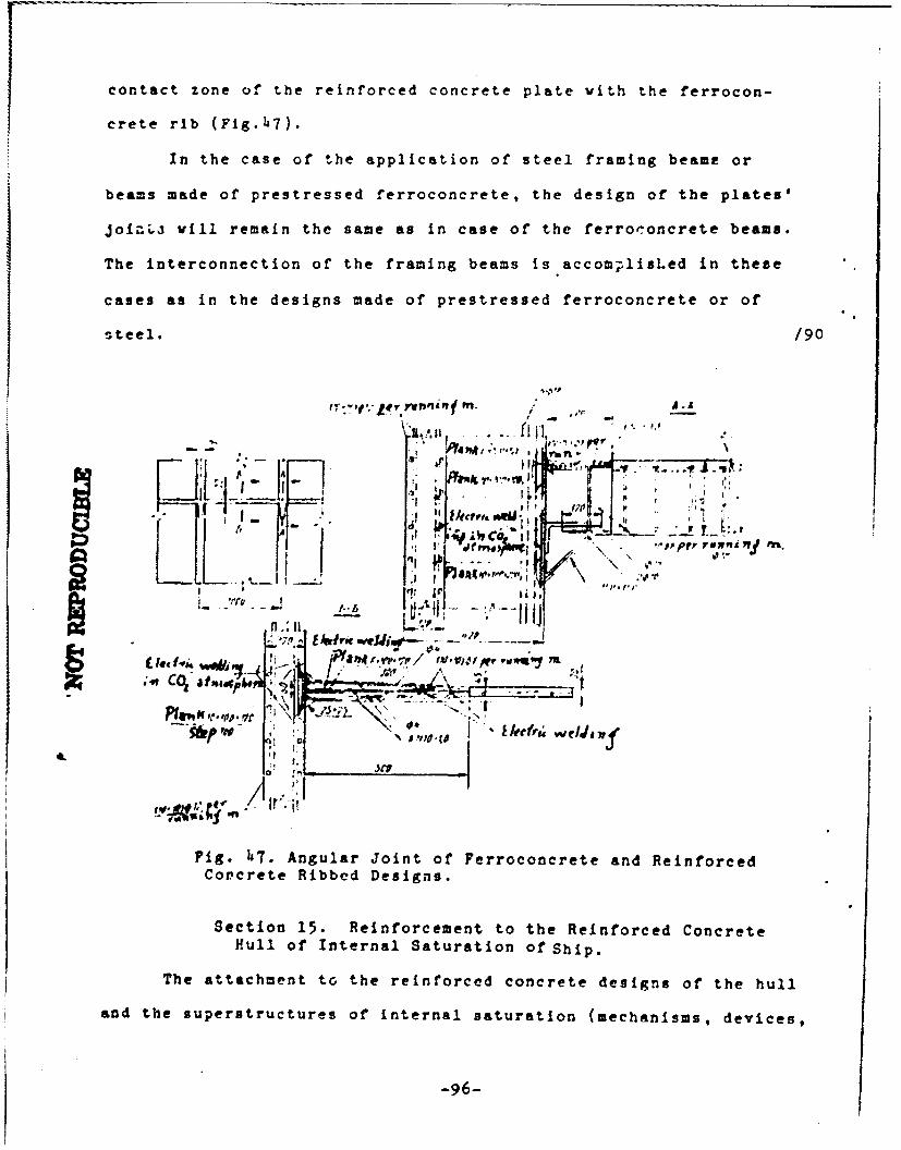
contact zone of the reinforced concrete plate with the ferrocon-
crete rib (Fig.47).
In the case of the application of steel framing beame or
beams made of prestressed ferroconcrete, the design of the plates'
joi.-L vill remain the same as in case of the ferroconcrete beams.
The interconnection of the framing beams is accomplisLed in these
cases as in the designs made of prestressed ferroconcrete or of
steel. /90
.':+,:-•€ rwn in• . / ,.r-I ., ,f v ¶l, " p '
A:4. I
lkct"Irv[ 1I . .. . . . 'a.i
U -; ,, c o,;p,,, ii-S ,t- r + ,.+j • •... ,'- , ---". 4
led f 'i wo it' / p
Fig. h7. Angular Joint of Ferroconcrete and ReinforcedConcrete Ribbed Designs.
Section 15. Reinforcement to the Reinforced Concrete
Hull of Internal Saturation of Ship.
The attachment to the reinforced concrete designs of the hull
and the superstructures of internal saturation (mechanisms, devices,
-96-

systems, rigging and equipment of the quarters) is achieved either
by means of inserted parts or with the aid of through bolts passed
through the design. The attachment with the aid of through bolts is
accomplished only to the designs not experiencing a constant water
pressure. The conduct of the attachment with the aid of through
bolts to the reinforced concrete is much simpler than to ferro-
concrete, since the hulls in the reinforced concrete plates car, be
drilled on the spot.
The basic type is the attachment by means of inserted parts.
The inserted parts car be ingtalled in the reinforced concrete plate
and in the ferroconcrete framiag beams. The attachment of the in-
serted parts to the 'einforced concrete plates can be accomplished
by welding to the rods of the intermediate mesh-wire, to thp rod
clamps, additionally inserted into the mesh-wire (Fig.48), and also
to the speci-l anchoring rods (Fig.49).
The type of the attachment of the inserted parts to the plates
indicated in Fig.h8, is preferable from the viewpoint of weight of
the design, however this joint operates much less efficiently to
-leavage than indicated in Fig.49. At the same time, the type of
attachment indicated in Fig.49, providing the possibility of
absorbing considerably higher separating forces, requires a local
thickening of the plate, which is inefficient from the viewpoint
of the weight of the design and the technology of its manufacture.
Therefore, if possible we should avoid the attachments to the
reinforced concrete plates of the saturation parts of the hull,
causing considerable separation forces, and conduct the attachment
of such parts to the framing beams (Fig.50). For the parts of the
filling of the hull, not causing any appreciable separation forces,
-97-

the inserted parts are fastened according to Fig.,8.
The examples of attaching the inserted boxes to the reinforced
concrete plates (with the use of the design solutions presented in
Fig. 49) are shown in Figs. 51-53.
All of the inserted parts intendel fzr' the attachment of
the internal filling of the ship to them, by degret -f load
state can be subdividided into three main groups:
1) the inserted parts for the attachment of the main and
auxiliary engines, the deck i.echanisms and devices;
2) the inserted parts for the attachment of the systei's and
pipelines; and
3) the inserted part.- for the attachment of the lightly-loaded
elements of saturation (electric lines, cable lines, the heating
devices, the lighting fixtures, etc). /92
C 0
Fig. 48. Attachment of the Tnserted Cleats (planks)
to the Reinforced Concrete Plates by Welding to theReinforcements of the intermediate Mesh.

A7A
Fig. 49. Attachment to Incerteu Strips to the ReinforcedConcrete Plates by Weldcing to the Anchoring Rods.
A L Ic~j~/93
Ar - wefll/
P, L. __ j 'Hu
Ae 5 Jri
9' - .

/94
33 ' v'a '
41 U UJ U u
No.
Fig.51. Fastening of the Rectangular Inserted
Box.
I 'Al.
Fig. 52. Attachment of Round Inserted Box. /95
The main and auxiliary engines are installed on foundations,
often formed with inserted stiffening ribs. For this purpose, we
use the framing beams and the specially installed ribs. The
-100-

attachment of the engines to the base plate is achieved by means
of inserted strips, welded to the anchoring rods (specially mounted
in the stiffening ribs) and to the fittings of the stiffening ribs
(Fig.54). The strength and the stiffness of thc engines' mounting
in the design of attachment shown in Fig.54, is determined by the
strength of the anchoring of the inserted strip-cleats and the
rib's stiffness. The dimensions and reinforcement of the stiffen-
ers and the dimensions of the anchors are established from the con-
dition of the absorption by them of the dynamic load from the
operating mechanisms.
-!
AL 'jAr F
AL J L
I'j L'. . . .j'
Fig.53. Attachment of the Inserted Part under theHatch Coaming.
To reduce the vlrbrations transmitted from the mechanisms
to the hull, between the base frame of the mechanism and the ferro-
concrete foundation,shock-absorbing linings are installed.
-101 -
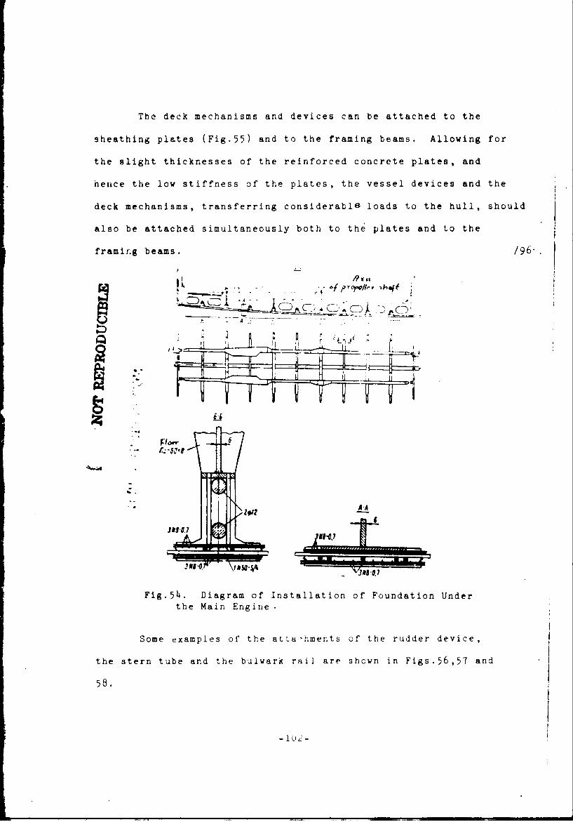
The deck mechanisms and devices can be attached to the
sheathing plates (Fig.55) and to the framing beams. Allowing for
the slight thicknesses of the reinforced concrete plates, and
hence the low stiffness of the plates, the vessel devices and the
deck mechanisms, transferring considerable loads to the hull, should
also be attached simultaneously both to the plates and to the
framing beams. 196".
SC-1 C -D C!
P'9"". .Ifprro/k hft
"r W-8•,2A.!
j- -4A
Fig.54. Diagram of Installation of Foundation Under
the Main Engine.
Some examples of the atta-hments of the rudder device,
the stern tube and the bulwark rail are shown in Figs.56,57 and
58.
-ifJ

S1,50
Fig.55. Installation of Foundation under the DeckMechanisms to the Reinforced Concrete Plate.
/97The reinforced concrete sheathing (planking) in the
region of installing the rudder me(hanism and the stern tube
(Figs. 56 and 57) is shielded by a steel sheet, since these
sections of the planking are exposed to the intensified effect
of the hydrodynamic forces. A similar protection of the rein-
forced concrete planking with steel plates is also used in the
area of installing the hawse holes (Fig.59) and the installation
of the stem. The a~tachment of the protective steel strips to the
reinforced concrete planking is achieved by their welding to the
intermediate rod or additional anchoring equipment.
Examples of the attachment of the systems and pipelines to
the reinforced concrete planking are snown in Fig.60.
In the case of the intersection of the planking plates by
the pipelines, it is recommended that their installation be achieved
in accordance with Fig.61. The installation of the bulkhead cylinders
can be conducted in accordance with Fig.63. In case of the use of
the design shown in Fig.63, the necessity is eliminated of the
preliminary concreting of the cylinder together with the design,

and the assembly of the connection is simplified. The tightness
of the joints is assured by using additional linings. Essentially,
'he connection in question is similar to that using the through
bolts. Therefore, by drilling the reinforced concrete and utilizing
the cylinders in the design indicated in FIg.62, we can simplify
greatly the assembly of the systems as compared with assembly to
the plates made of standard ferroconcrete, and accomplish it in
analogy to the practice of stecl shipbuilding.
qwits _r ?5: so
Fig.56. Attachiment cf Rud-der Device to Hull.

/98
L Not REPRODUCIL
I A;Ii-ll - ________ I, _ ,•
k• .u
A-A
reol
Fig.57. Attachment of Deadwood Tube to the Hull.
raft,
/99
Fig. 58. Attachment of the Fig.59. Attachment of Hawse
Bulwark Rail to the Reinforce4 Hole to the Reinforced
Concrete Planking. Concrete Planking.
-105-

,., . o I . •. , "
Fig.60. Examples of Fastening t.he Pipelines to the
Plates of the Peinforced Concrete Planking. 1-rein-forced concrete planking; 2-corner piece; 2-clip;4-linings; and 5-inserted cleat. /100
• , ,,* ' .,. I,
I v
n n n 11 n P
u u LiJ J u u
Plats-o th .enfoced CocrtePlnkng-1ren
•.•--. 1-- -lin ing andI1 / 5-i 'e-e cl-at-/10Aa
n n nl n nI nl
11 11I, i it 1 I ifII II II t II l!I' '
I t IF -i -I # $ i "II i! II ,II I ! '
fII
i.II
U."i L pr:,rnUP 1 u LO eru
Fig.61. Attachment of Pipeline Which Intersects the Platesof Reinforced Concrete Shenth4 ng.

hi'(V :46e
Fig.62. Attachment of Pipe-line cylinder.
Fig. 63. Attac1hment of Illumin-sting Device to Reinforced Con-
" ~crete Sheathing vith Aid ofInserted Sheets; e-illumina-
- - •} tor frame; 2..Insert -6;
3- anchoring rods 6.i0
"I.F iFig.6. Fastening of Illuminating
a Device to Reinforced Concrete Hull|zr Sheathing with Aid of Dovel Pins.1 i- metal ring; 2-rubber -inuing,
3- illuminator frame; 4-dovel pin
-107-

Similarly tc. tne attachment of the bulkhead cyliners, we
also accomplish the attachment of the illuminating device to /102
the reinforced concrete sheathing (Figs.63,6Z).
As a rule, the attachments indicated in Figs. 63 and 65,
Just as the fastenings using the through bolt.-, are utilized
in the hull elements not experiencing a prolonged effect from
water pressure.
Along with the bolt type of fastening, use is also made
of the fastening based on inserted parts (Figs.61 and 63).
The inserted parts for the attachment of the lightly-loaded
saturation elements (electric wires, lighting fixtures, etc.)
are rarely utilized. In these instances, the attachment with
the aid of cement-type or epoxyd glues is becoming more and
more popular.
-108-

Chapter III. TKCHNOLGY OF PRODUCING TKE D1.IGNS AND HULLS OFSNIPSFROM REINFORCED CONCRETE
Section 16. Effeot of leinforoed Conorete on Seleotion of
Method for Building a Ship
The quections of the technology applied in the preparation of the desig
and the building of ship hulls of reinforced concrete have primary importance.
The relatively slight thickness of the parts, the thin protective layer, the wire
mesh reinforcemerti and the cement-sandy concrete introduce features into the
technique used in producing the reinforced concrete designs. The indicated fea-
tures of the material and also the quality and care used in performing the opera-
tions determine to an even greater extent than for standard ferroconcrete the
operating capability of the marine reinforced concrete designs.
The hull. of the reinforced concrete ships as well as the ferroconcrete
ones can be made monolithic, sectional-monolithic and by sectional methods.
At the present time, the monolithic method is mose popular. The sole ex-
ception is the building of a self-propelled driftwood hoisting floating crane with
a lifting capacity of 10 tans.
The monolithic nethod does not require the application of extensive and
complex equipment, while the construction of the reinforced concrete hull of a
ship by this method can •e accomplished in the building slip areas without speoial
equipment. The positive aspects of such a method condition the economic effectiveness
of its application in a case cf the individual and small-scale construction of
ships, and also in the building of ghips of small dimensions.
The application of reiniorced concrete in place of ferroconcrete simplifies
the monolithic method of building ships and makes it more effective. This Lo /104
achieved because for making the reinforced concrete hull monolithic, in distinction
from P_ ferro.-.ncrcte null, cement forms are not needed. The cement-mandy cnncrete
is retained well by a bundle of thin fine-mesh screens, in which the concrete is
pressed by a worker and is rubbed simultaneously from both sides so that the operation
of making it monolithic becomes similar to a careful plastering.
If we take into account that the coat of the form during the conatruotion
of ferroconcrete ships by the monolithic method reaches 20% of the cost of the ship
hull, there become quite apparent the economic advantages which are achieved with
the formless production of the monolithic reinforced concrete hulls in the monolithic
method of their construction. As a result of the ,'ircuftstance indicated, the area
of effective application of the monolithic method of building the reinforced concrete
ships expands more rapidly as compared with the ferroconcrete vessels.
At the present time, we have not yet developed the means for the mechanized
production of the sectional reinforced concrete ships, and the accompiishmwnt of
the intersectional connections of them is still more laborious than for the design
made of ordinary ferroconcrete. Therefore, the use of the formless monolithic
method of construction should be regarded asAtechnically and economically justified
solution for the present time, in spite of the general tendency in shipbuilding to
convert to the prefabricated (sectioial) methods.
It the same time, the disadvantages typical of the monolithic construction
mcthod (manual labor, iong duration of the cycle on the building slips, and in part
the seasonal nature of the wo'k) provide evidence that this method does not match
the modern level of developmert of shipbuilding production. Therefore the intro-
duction of the prefabricated method in the mass production of reinforced concrete
ships and in the creation of the necensary highly-productive equipment for producing
the prefabricated designs and the formation of a ship hull on the slip is a pres-
sing modern requirement.
In the prefabricated method of construction, the division of .he vessel hull
into sections and the sequence of forming the hull on the slip are established by wea
of comparing che prime cost &-d the cyc½e of building in case of different types.
We consider as efficient that division of the hull into sections and the sequence

of its 'rmation on the slip under which we achieve the loant prime cost and
shortest duration of shipbuilding time.
The pattern of sequence for forming the ship huil on the slip should
provide for the maximal parallel setfip for conducting the hull, mechani'Ml and
electrical assembly, conduit, insulating tasks, and also the work involved in
equipping and finishing the quarters. Taxing into account the effect of the factors
of a design nature, we can conclude that in a general case, the method of building
a reinforced concrete ship should be selected in dependence on the type cf ship /105
under construction, the configurations, dimensions, design features, xerN9a ao5ii
ditior. of construction, and the production-engineering conditions of the ahipyarl.
Section 17. asio Poetures of bngineering in the Construetioe of
aeinforoed Conorete Ships
We indicated in Chapter 1 that reinforced concrote ir essence is a thin-walled
type cf ferroconcrete, whereby there is winly established 11a specifica both of the
&ctual reinforced concrete design as well as the tec.nn-logy of their produc-tln.
If we consider the basic technolog-ical operations which are aooompil"had
during the production of the reirforced concrete designs x t -e *".- •iz o, i
hulls in reinforced concrete ships, we can. be convinced that bL'-cail: t.; Ao not
differ from the principal teczi~ologtcal operations applied in the hui],itng of shDps
from standard ferroconcrete. Both in the case of utilizing re.lniorc.• con.crte aid
in the case of using conventional ferroconcrete, the following tasic work stages take
placet The preparation of the reinforcing material; the preparation of the irert
masses; the preparation of the reinforced f:-ames of the prefabricated parts or of
the ship hull as a whole and the concreting of the prefabricated Pfr*%. or the tak cf
making the hull monolithic (under the monolithic building method); the heat-moisture
processing of the coLcrered design; the assembly of the prefabricatel parts on the
slip and the performance of the intersectional connections; the finishing of the hull

designs; the testing of the hull for watertightness; the assembly of equipment,
devices, systems, etc; the insulation and finishing of the rooms on board; the lower-
ing of the ship into the water. At the same time, certain engineering operations
in the building of ships from reinforced concrete have a number of features which
must be taken into account in developing the technique of building reinforced concrete
ships, along with the requirements imposed during the construction of ships made of
conventional ferroconcrete.
Not dwelling on the characteristics of the engineering operations, comion
for the reinforced concrete and ferroconcrete ships, which are described fairly
well in the literature on the technique of building ferroconcrete ships *, let us
examine only the basic features of performing the operations involved in building
ships of reinforced concrete.
Preparation of Reinforcing Material. The rod-type reinforcement utilized
in the construction of reinforced ships is subjected to the same processing as /106
in the building of ships from standard ferroconcrete (cleaning of rust and scale,
scraping, cutting, bending, etc).
The reinforcement steel, arriving in the form of rods and in coils, is
strkightened, cleaned and cut on the truing-cutting automatic lathes. The fiber
gratings (woven meshes) during the preparation are lubricated to protect them from
-orrvelon, and in such a form are delivered to the shipyard. The anticorrosion
lubricttiori of the screens must be removed, since in the presence of a lubricant,
the adhesion of the concrete with the mesh wires is reduced consideratly.
The cleairing of the lubricant from the screens is acccupiished by a thermal
-r chemioil method.
*K.. A. kbromimov, A.A. Mil'to, A.M. Pasinsgiv. "Technolua ol" Fe:,-•Prute qhx ing",Sudostroyeniye (Shipbuilding), Leningraa, 19ý-. N .Y. Yegoro v. "iecl-no. py c,,building Perroconcretp SLi?.,po', Rechizdat (River rub!.nhing House', •. -,,ow, lIb_

Under the thermal (h~at) method of cleaning, the screens are held in heating
furnaces at a temperature of 250-300*C until the lubricant has been completely burned
away.
The chemical cleaning of the screens is accomplished in washing machines,
and in the absence of such, can be cleaned in any tank with a hot alkali solution
of the following composition (gl1):
Caustic soda (sodium hydrate)......40-50
Sodium carbonate ............... .... 80-100
Liquid glass ....................... 10-15
The treatment of the mesh is conducted at a solution temperature of 80-90*C
with a subsequent washing in hot water at a temperature of 70-800C. To avoid the cf-r-
rosion of the screen from which the lubricant has been removed, its cleaning should
be conducted directly before use. The cutting of the screens according to the
dimensions of the designs being produced is conducted with cutting shears (elec-
trical or manual).
Assembly of Reinfs.oing Frames. The ribbed reinforced concrete designs
can have metal and ferroconcrete ribs (beams of the set).
The process of producing the reinforced frames include:
- preparation of the reinforced parts (of the bundles of woven screens,
frames of ribs and supports);
- assembly and welding of the reinforced parts in the spatial designs,
i.e. the flat or curved reinforcing sections; and
- preparation of reinforcement for the intersectional joints and monolithic
purts.
The assembly of Ghe reinforcing frames of the ferroconcrete beams of a set,
of the intermedi-ti screens of the reinforced concrete plates and of various su,)ports
in the production of the ribbed reinforced concrete designs does not differ in 'Any
wery from the assembly of the reinforced designs made of ordinary ferroconcrete.

However, the assembly of the reinforced frames of the plates has certain features.
As is known, the reinforced frame of a plate consists of several layers of thin
meshes and can have an intermediate rod-type grating. /107
In the production of the elements of the reinforced concrete design., the
thin wire screens are usually assembled into bundles, in which the screenc are
interconnected with the aid of binding wire or by spot welding. The number of
such joints must provide a sufficiently smooth surface of the bundle (without
bulges) and the required assembling connection of the screens with each other.
In the case of the combined reinforcement, the reinforced frame of a
plate is assembled from two bundles of fine screen, with a number of layers pre.
scribed according to the plan, and with an intermediate rod-type grating (for
welding or for wire twisting). First, on one of the bundles, we lay the inter-
mediate rod-type screen, which is attached to it with binding wire (in twists)
or by welding; then the second bundle of screene is installed; it is also attached
to the intermediate rod-type screen.
The welding of the wire screens between each other by lap-welding and in
bundles is conducted with the universal spot-welding tool UTP-3, with the applica-
tion of copper laminated electrodes 30 X 60 mm, according to the conditions
(approximatelyp
Strength of welding current ........ 3600 amps
Secondary voltage ................. 11.5 voltsWelding time ....................... 0.05 sec
The sets of wire screens are welded with the intermediate ro4-type screens
and with the reinforced frames of the ribs also by the universal welding tool
UTP-3 with the application of copper electrodes 5 - in diameter roughly according
to the conditions:
Force of welding current.......... 8200 amps
Secondary voltage ................. 11.5 volts
Welding time ....................... 0.05 sec

The rods 8 mm in diameter and up are connected by vat-type
butt electric welding with semiautomatic devices us'ng alloyed
wire or in a carbon dioxide atmosphere. The rods with a diameter
less than 8 mm are welded together by the seam lap welding using
semiautomatic devices.
in the reinforced frames of the sections, we install all of
the inserted parts, not extending beyond the limits of the plate's
thickness. The inserted parts are fastened to the reinforced frames
by welding with semiautomatic devices in a carbon dioxide atmos-
phere (or by alloy wire) to the intermediate screen, the frames
of the ribs and supports, or to the specially installed anchoring
rods.
The electric welding by alloy wire and the welding in a
carbon dioxide atmosphere are performed in the same way as during
the assembly of the reinforced frames of the ship designs made of
standard ferroconcrete. /10b
The various slots and openings in the reinforced frames for
the hatches, vents, lights, compartments, etc. are made acc.,rding
to the marking done with a gas-type cutter.
In the case of the monolithic method of construction, the
fine meshes in the distribution over the outlines of the ship
are stretched to eliminate sagging. In this connection, the rein-
forced designs of the monolithic hull elements can be assembled
on the slipway from the prefabricated reinforced sections.
Preparation of Concrete and the Concreting of Designs. The
preparation of the cement-sandy concrete is conducted in the mortar
mixers or in the con-,te mixers with forced agitation. The higher
requirements imposed on the mixing of the cement-sandy concretes
as compared with the standard concretes are caused on the one hand
-115-

by the relatively low water-emen.t ratio for these concretes,
A and on the other hand by the large specific surface of the inert
(sandy) filler. In connection with this, we require a more care-
ful and extended agitation of the mixture for reducing it to a
uniform consistency.
In order to provide the careful mixing of the concrete
batch, the materials are loaded into the concrete mixer in the
following order: First, we add the cement and sand,and then the
dissolving water. The duration of the mixing is not less than
2-3 minutes, and is establishea finally on the basis of the
smoo.hness of the concrete mix, established visually.
The monitoring of the quality of preparing the cement-sandy
concretes includes: the checking of the quality of the components
(cement, sand,water and additives), the control of the accuracy
of batching the components and the verification of the convenient
handling of the prepared mixture. From the listed control opera-
tions,the primary one is the checking of the handling convenience
of the concrete mixture, which is established not bared on the
settling of a standard cone but with a technical viscosimeter,
wherein the index of placement, measured in seconds, is established
depending on the quantity and number cf the -tire screens, and in
each actual case is specified on the basis of experimental
checking. For the reinforcement used in the reinforced concrete
ship designs, the placement index comprises 15-25 seconds.
The selection of the composition of concrete mixture can be
conducted by any method, under the condition of complying with the
-116-

prescribed requirements for the properties of the concrete mix-
ture and of the hardened concrete.
The reinforced concrete sections can be prepared both by
the stand and by the ass,:mbly-line methods. The feasibility of
using any given method of producing the sections depends on the
type, dimensions and weight of the section, and in each actual
case is established by a technical-economic calculation. /109
The basic technological sequence of producing the reinfor-
ced concrete sections in case of the btnch or assembly-line
methods is identical and includes:
- preparation of forms;
- placement of the reinforcing frames in the forms, and
the installation of falsework for attaching the outlets of the
wire meshes and the reinforcing rods;
- the placement and packing of the concrete;
- the heat-moisture processing (steaming) of the corcreted
sections;
- the stripping of the sections and their conveyance to
a warehouse or a slipway; and
- the treatment of the connecting edges of the sections.
In case of the mechanized placement, pa.cking and smoothing
of the concrete mixture with vibrating-shaping units, the fiat
ribbed sections are concreted :n the metal form-matrices below
in the form of ribs; the ribless sections are concreted on the flat
metal stands.
. -117-
The sections of curvilinear shape are made in vonden forms,
trimsed in order to increase their turning ability ana to improve
the quality of the section's surface with water resistant plywood
or with thin-sheet steel. Iluch sectirns can be concreted both below
and above, with ribs.
The placement of the concrete in the sectioLs (curvilinear
and flat, having reinforcements), made upward in the form of ribs,
is accomplished manually during the packing of the concrete with
vibrating rods, with sectional and deep electric vibrators.
For the production of the sections(especially of the curvi-
linear ones), and also of the monolithic hull elements, 'oe can
apply the method of the formless concreting. In this case, the
concrete mixture is applied by hand to the reinforcing frame or by
guniting (by spraying) with the aid of compressed air. During the
period of the concrete's setting, the surfaces of the concreted de-
signs are rubbed with dry cement. The framing beams Are concreted
similarly to the monolithic ferroconcrete designs with the applica-
tion of falsework.
An important moment in the preparation of the hull designs from
reincorced concrete is the provision of the necessary protective layer,
uniform over the entire surface of the design. This requij-ement is
quite significant, since a reduction in the protective layer to
a value of less than 2-3mm does not guarantee the required corrosion
resistance of the designs, while its increase above 3 mm leads to a
decrease in the crack resistance.
Under the conditions, wheL the methods of mechanized production
of the ship reinforced concrete designs have not yet been worked
out, the attachment of the required protective layer is achieved with
-113-

the aid of the reinforcing rod-linings with a diem'ter e illing
the value of the protective layer. The rod-linings are placed in /110
the form-matrix and on the bundle of screens before the concreting
of the designs with a step (spacing) of 150-200 mm and after the
packing of the concrete they are removed. The grooves which are
caused thereby are filled by an additional brief vibration of the
designs in the location of the linings.
Heat-Moisture Treatment of the Concreted Design. The aging
of the concrete of the reinforced cement designs can occur under
nuturally moist conditions or during a heat-moisture treatment of it.
The thermal-moisture processing of such designs, in distinction
from those made of standard ferroconcrete, is conducted according to
the "soft" conditions with approximate parameters: the gradual heating
to a temperature of 60-70 0 C with a rise in temperature of 10-150
per hour, isothermal heating at maximal temperature of 60-70 0 C for
two-three hours, then a cooling at a rate of not more than 15-20O
per hour.
Assembly of Hull on the Slipway. A feature of the technology
of the slipvay construction of the ship hulls made of reinforced
concrete is the conduct of the intersectional Joints and of the mono-
lithic elements.
The reinforced concrete sections are interconnected and are
also Joined with the monolithic elements of the hull by way of by-pas-
sing thc reinforcing outlets (of the wire meshes and of the reinforcing
rods), and also are connected to the assembly ir.serted parts.
The fitting outlets of the sections are c,•nnected by welding in
the following technological sequence:
-119-

tr 'tOT REPROD-CCIBLETA Is 12
POCOMM.d Cc~mt-"Oans of Anticxrrogic Coatingm for Ninforced Cm,,t Temisi Duio
Content metsu*s UmWofGv umber of is upplioaui
Of CONALAu (paint) (by miht I N
brus Opaving
IiO Vnoi,4101 oe Prepae &~d 0 plaw of ~am
p &?twolma w ped v 00 . 3 -slutift ve bitM is pe-6&7-66) 11* (11 3)
so-V~s.Q0A31P~ (OW3 1928-66) :treasdorme, mIft r p p- oilwbot csmt (Ooinmav).ftlew aebstes. 61" or C.Mwt
- P laoque~ PedblaafWNcmpestiga I1
(*tbod filler)pet"r410m Utz,pj Pods Iet-b...L--*-V Ii
Oth~nl laqmr<fU 1267-50 1W)
NýNfiller)petroletme wblt
fillm ui best dimbew orluM~sii Podr Ste.
sem(0Dmt 1n II
'bi*Iua~wa laoyea No.411 41) 2 I'W Ise-4i as Ohsm'102torI (aaqoositim lil0)
a~a laoqumr(!U 1267-56kW) r-
12binl pelaes, 1 u X rpe t rg tu
oinpositiaA II
etbmel loqaaor N
**olp~ III
oepositizm II
comotsa III
or.a W-H (V1U KU 48"7?) 1Bane Z-4M (M! IM 495?)

- the welding of the outlets of the distributing reinforcing
mesh with a semiautomatic device in an atmosphere of carbon dioxide
or alloyed wire;
- the spot-welding of the wire meshes to the outlets of the
distributing mesh with the welding tool, type UTP-3;
- the tank welding of the outlets of the framing beams' fittings
by semiautomatic welding devices in a shielded arc of carbon dioxide or
of alloyed wire.
The inserted parts are also welded with the semiautomatic device.
For falsework, use is made of the metal or wooden-metal stock
panels.
The intersectional joints are concreted with sandy cement of the
same grade and composition as the concrete in the sections, but
having a high mobility of the concrete mixture (roughly 10-15 seconds).
The concrete mixture is delivered and placed in the connections
with mortar pumps. The packing of the concrete in the vertical joints
with the two-sided f&lsework is conducted during an intensive vibra-
tion with electric vibrators fastened on the falsework; the concrete
in the horizontal joints is packed with the area-type electric vibra-
tors. /113
Attachment of the Inside Equipment of the Ship to the Reinforced
Concrete Designs. The reinforced concrete can easily be drilled, and
this property of it is utilized to a full extent in the accomplishment
of work on attaching the internal equipment of the ship to the
reinforced concrete sheathing.
To the designs not experiencing the prolonged effect of water
t

pressire (bulkheads, partitions, platforms and decks), the attachment
of the inside fittings can be done with bolts. In this connection,
the holes of the required diameter are drilled directly on the spot.
Such a method of attaching the internal fittinas of the ship to
the reinforced concrete sheathing is much simpler and more economic
than the attachment on the inserted parts.
Application of Anticorrosion Coatings to the Reinforced Concrete
Sheathing of the Hull. The standard shipbuilding ferroconcrete pro-
duced with high quality is a sufficiently long lasting and corrosion-
proof material, which is confirmed by the many years' practice of
operating the various facilities made of it, including the ships
and docks. However, the corrosion resistance of the reinforced con-
crete sheathing of the hull, as a result of the low value and the
unreliability of the available means for controlling the thicknesses
and density of the protective layer of concrete, can not be guar-
anteed for the full servicc life of the floating facilities in view
of the difficulties associated with providing all the technological
requirements during the production of the designs.
In connection with this, for providing the operational reliability
and the long life of the ships, to the external sheathing of the
reinforced concrete hull to the level of the main deck, we recommend
the application of anticorrosive protective coatings.
The compositions of the recommended anticorrosive coatings for
application to the reinforced concrete sheathing of ship hullb are
indicated in Table 12.
Before the application of the protective coatings, the concrete
surface is cleaned of contamination and incrustations of corrosion
-121-

with the aid of wire brushes or other tools, and then it is c2eaned
with compressed air. If on the concrete surface, we find large
flaws, cracks and dents, they are repaired by rubbing with a cement-
-sandy solution in the ratio of 1:2 (by weight). The moistness of
the surface layer of concrete prepared for the application of coatings
should not exceed 5-6%. The moistness of the concrete surface is
determined by drying to a constant weight (at a temperature of 100-
150 0C) of samples taken from the concrete surface in two-three
places at the depth of the protective layer. The percentage of
mfistness is established with the formula
A = a-b/a • 100,
where A = the moistness of concrete;
a = the weight of sample prior to drying;
b = weight of sample after drying.
The protective coatings are applied to the concrete surface on
a previously applied base.
As a base, we use:
- for composition I of the protective coating- a solution of
oitumen in gasoline of composition 1:3 (by weight);
L for composition II - bitumen-ethanol lacquer with a composition
of 1:10;
- for composition III- ethanol lacquer; and
- for composition IV - base E-4021 (VTU KU 496-57).
The base is applied by hand or mechanically with the aid of
compressor-type or compressorless sprayers, in a regular thin layer,
without leaving uncovered spots or inflows.
12

The working consistency of the base (viscosity) in tne paint
sprayer operating under a pressure of 3-3.5 atm should be within the
limits of 18-22 seconds based on the VZ-4 viscosimeter at a tempera-
ture of 20 0 C. The working viscosity of the bases is attained by
diluting them with the solvents:
- for mixture I - with gasoline;
- for mixtures II and III, with ethanol lacquer; and
- for mixturb IV, with the R-40 solvent or acetone.
For the development of a strong coating, the base should be well
dried. An insufficiently dried film of the base under the effect
of the solvents, forming the lacquers and the paints, can dissolve,
as a result of which bubbles and wrinkles are formed. The normal
length of drying the bases for the recommended protective coatings
is 24 hours at an ambient air temperature cf 18-23 0 C. The painting
with a cold bitumen composition (mixture I) is conducted at a com-
position temperature not below 60 0 C and at an ambient air temperature
not below 8 0 C. The composition is applied to the protected surface
with a brush and is smoothed out with a wide spatula.
The paints, lacquers and enamels (mixtures IIIII and IV) are
applied to the concrete surfaces (already provided with a base) with
paint sprayers. Under the necessity of performing the work with a
brush, the paints, lacquers and enamels are thinned to a working
viscosity with the appropriate solverts.
The painting of the outer surfaces (for all mixtures of the coat-
ings) is conducted at a temperature not below 80 C; the derformance of
the painting tasks during rainy weather is not permitted. After the
application of each layer of paint or enamel, we conduct a drying
-123-

of the coatizg in accordance with the technical conditions for this
material. After the application of the specified number of layers,
the coating is subjected to a final drying fot two-three days./115
Section 18. Examples of Construction of Reinforced Concrete Shipby the Monolithic Method
The domestic and foreign practice has fairly extensive experience
in the monolithic construction of the hulls of reinforced concrete
ships.
In Italy, in 1943, at a shipyard in Venice, the construction was
started o, a motorship with a deadweight of 400 tons and of three
self-propelled transports with a deadweight of 150 tons each. How-
ever in connection with the military operations developing in this
area, the construction of the ships was interrupted. After the
end of the war, the construction of the reinforced-concrete ships
in Italy was renewed.
In 1945, at a shipyard in tnzio, a motor-sailing vessel "Irene"
with a deadweight of 165 tons was built. In the later years (1945-
1948), in various regions in Italy, there were built frcz reinforced
concrete launches, yachts, pontoons, and also transport, fishing and
other ships.
The sailboat "Irene" was built by the shipyard workers at the
yard in Anzio destroyed by the war, at which no mechanical or elec-
trical supply was operating. For its construction, there could be
used only the slipway and the launching platform (track).
Specifications of the Ship
Length between perpendiculars, m .......... 21.6
Maximum length, m ........................... 6/24 *
t
-124-

Molded depth amidships, m ............ 3.2
Power of main engine,h.p .............. 316
The hull of the sailboat is of ribbed design with a transverse
framing uystem. The lines of the hull are the conventional curvi-
linear ones.
The design feature of the hull consisted in the fact that the
framing beams were ferroconcrete; the sheathing and the deck flooring
were of reinforced concrete. The framing beams with a width of 60-80mm
had a height ranging from 250.M (for the side branches of the frames,
beams and carlings) to 400 mm (for the floors and keelsons). The
stronger ferroconcrete beams were located in the area of the keel,
the bow and the deck stringer. The outer sheathing made of reinfor-
ced ;uacreto was 35 = ih thickness.
The construction of the ship was accomplished in the open
slipvay area beneath the keel. Initially on the slipway, we
assembled the skeleton of the hull's framing beams (both the longi-
tudinal 4nd the transverse ones). All the framing beams had rein-
forcement typical for the standard ferroconcrete ships. The
assembled reinforced framework comprised a fairly rigid spatial (three
dimensional) design, reproducing the form and outlines of the ship
under construction. Then from the outside of the hull (with the ex-
ception of the deck), on the reinforced carcass of the framing, one
upon the other we placed in succession the foiloving: four /116
layers of fine wire mesh, wcighing one k9 per @quas ister, three
tiers of reinforced rods with a diameter of 6 mm (two tiers were
placed in a longitudinal and one in a transverse direction) and once
again, four layers of wire mesh. The three-layered reinforced design
-125-

of the hull sheathing obtained in such a manner was connected vith
steel binding wire.
Fig.65. The Reinforced Concrete Yacht "Irene"During the Construction Period.
The reinforced carcasses of the framing beams were connected
with the reinforced concrete sheathing in the process of Its rein-
forcement by way of bending the outlets of the yokes around the rods,
located in the sheathing between the mesh bundles. The transverse
bulkheads, the platforms and partitions within the hull were rein-
forced simultaneously with the reinforcement of the outer sheathing.
All of the reinforcing tasks were done by hand.
Upon the completion of reinforcing the hull elements (with the
exception of the deck, superstructure and deck-house) we conducted
their concreting,without falsework, continuously from the bottom to
the deck. For the concreting, we used sandy concrete of plastic
consistency with -he output of 1.000 kg of cement per cubic meter of
concrete. In the concreting of the reinforced concrete elements,
the concrete was applied to the reinforced framework by hand from
within the hull, an! was pressed through the screens; at the seine
-126-
time, from outside, we accomplished the smoothing and finishing of
the concrete surface (Fig.65). The deck and also the stern super-
structure with the deck-house were reinforced, and then were also
concreted after completing the concreting of the hull elements lying
below. /117
To the finished hull, there were applied the anticorrosive
and anti-fouling coatings.*
The reinforced-concrete pleasure yacht "Nennele" was built in
Rome in 1948.
Specifications of the Yacht
Maximum length, m ........... 12.5
Length along the design
water line m .............. 9.5
kaximum width, m ............ 3.2
From a design standpoint, the hull of the yacht "Nenuele" dif-
fers from the hull of the sailboat "Irene" chiefly by virtue of the
fact that in place of the ferroconcrete beams, as framing use waa
made of the steel inch pipes. The yacht had a reinforced concrete
sheathing with a thickness of 12 mm.
In the constructiva of the hulls, the framework was first assembled
from steel pipes. Then, the sheathing of the hull and the transverse
bulkheads were reinforced. The reinforcement of the outer sheathing
consisted of seven layers of wire mesh and of one tier of longitudinkl
rods with a diervter of 6 mm, set 50 mm apart. The longitudinal rods
divided the me&., reinforcement into two bundles (three layers of Aeah
* The composition of the coatings is not giver in the literature.
-12-

within and four layers outside of the hull.
The hull was concreted from inside; the sandy concrete was appiled
manually to the meshes and was smoothed out from the outside. After
the completion of construction, the yacht was hauled on a truck to
Anzio and launched into the water.
Subsequently, the basic engineering principles used in building
the yachts "Irene" and"Nennele" were subsequently applied in building
the small reinfo:ced concrete vessels in other countries, especially
in the building of the pleasure cutters aod the commercial ship.
with a length ranging from 7.3 to 16.7 m in England and New Zetland.
The monolithic method was also applied in building the reinforced
concrete yachts and launches in our country. In this connection,
along ith the formless preparation of the hulls, in a number of cases,
in the concreting, falsework was used, which generally spesking is
inefficient, but evidently this took place because of the insufficient
experience.
An example of producing a reinforced concrete hull with the
application of a cement form (mold) can be provided by the building of
the yacht "Tsemental". The basic difference in the tecnhique used
in building the yacht "Tsesental" from the method used in building
the "Irene" was as follows.
First, the hull of the yacht was built upward from the keel on a
previously prepared form-mold, in the capscity of which use was made
of the hull of a wooden yacht, also installed with the keel upvkrd.
The reinforcing framework (pla-ed in the mcid) of the hull sheathing,
consisting of five layers -,f wire mesh No.10, was concreted continu-
ously ;rom above downward, i.e., firat the keel and then the *'de /118
were concreted. After the attainment uy the concrete of the
-12-

necessary strength, the reinforced concrete shell was removed from
the form, placed on the slipway with the keel downward, and the
finishing (trimming) of the internal surface of the reinforced con-
crete sheathing was conducted.
Secondly, the hull framing was installel after the preparation
of the reinforced concrete sheathing (of the hull shell). The
previously bent frames (ribs) made of steel pipes were fitted in
place within the hull and attached to the reinforced concrete sheath-
ing by wire splices which were passed through the small openings
in the sheathing, punctured from both sides of the frames through
each 120-180 mm and subsequently made monolithic. After the attach-
ment of all the ribs, the installation of the beams of the deck and
superstructure was conducted; the transverse bulkheads, the deck and
the superstructure were reinforced. The concreting of the deck, the
transverse bulkheads and the superstructure was achieved without the
use of a form (mold).
In the period from 1957-1964, a group of sailboat enthusiasts
built the reinforced concrete yachts "Opyt" (Experience), tProgress"
and "Mechta" (Dream). The hulls of the yachts were made with the
keel upward, in which the basic difference from the technique of
building the "Tsemental" consisted in the fact that in the place of
the form, use was made of the framework assembled on the slipway
from the duplicated outlines of the hull of the wooden templates,
which were interconnected by wooden rods. Along the aligned frame-
work, we conducted the reinfcrcement of the hull, consisting of rods
mainly 6 mm in diameter, and of 6 layers of metal wiie mesh.
-129-

The hull was concreted without the use of a form, by way of
applying a cement-sandy concrete made of a mesh reinforced design.
By the monolithic method, without the use of falsevork or
wooden molds, ye built the reinforced concrete launch "Energostrolteil"
(Power Ouilder) which was launched in autumn of 1960. The reinforce-
ment of the hull framing of the launch was achieved with rods of a
smooth profile, having a diameter of 14 and IC mm; the reinforcement
of the sheathing was done with five layers of wire mesh, with a
mesh size of 10 X 10 mm, and wire 0.5 mii in diameter. All of tile
framing units were assemble, on the slipway in the framework in
position with the ke-. downward, and were connected by electric
welding. Prior t,. the reinforceLent of the sheathing, the rein-
forcing framework was taken from the slipway and turned into posi-
tion witL the keel upward.
The con:reting of the hull was accomplished with two methods.
First, the concreti was applied from outside, and to speed up the
hardening oi the concrete, the hull was subjected to steaming out in
a chamber, and then in the same place, the hull was turned with the
keel downward,whereupon it was concreted from inside and again
steamed out.
The exapples which have been reviewed of the monolithic con-
struction of small reinforced concrete ships permit us tc confirm
the finding previously made to the effect that from the technological
and economic standpoint, the most improved is the monolithic method
includirg the use of the formless concreting in one step, which Is
achieve,- fairly simply in the construction of e ship in a position
with the keel downward. Such a construction method, requiring a
t
-130-

twofold concreting of the hull, can also be effective for the
small vessels (such as the sloopz and small yachts), especially if
as a mold (form), we can utilize the hull of a ship which has gone
out of commission.
Section 19. Examples of Building Reinforced ConcreteShips by the Prefabricated and Prefabrlcated-Mono-
1ithic Methods
The only example at the present time of the prefabric'ated
method of building a ship with a hull and superstructure of rein-
forced concrete is the self-propelled pontoon hoisting crane with
a lifting capacity of 10 -ons, built in our country in 1964.
The designs of the hull and superstructure of the pontoon
crane, developed with consideration of their production completely
by the prefabricated method, are reviewed in Chtpter 2.
The hull is assembled from 45 plane and 2 curvilinear ribbed
sections; the super3tructure is made of 15 plane sections. The
maximal dimensions of the sections comprise 11.3 X 2.1 ml the
weight is up to 2.5 tons.
The hull sections were interconnected mainly by welding the
reinforcement outle..s bnu che inserted metal parts, with a later
wonolithizing of the iniersectional joints with sandy cement (Fig.
66).
The intersectional ýoincs ant the connecting edges of the
plates of the sections had a thickening up to 50 mm owing to the
reinforcement uf the conAtact zone and the adjacent edge-plates by
the welded frameworks made of rods with diameters of 6 and 10 mm.
In this manner, the design of eonneitin. thc iei. -orced concrete
sectiuns in the given instance does not differ appreciatly from
-131

that applied in building the ship hulls of cunventional ferro-
concrete. The sections of the superstructure were interconnected
by welding the inserted parts, and by mounting on bolts.
The attachment to the reinforced conciete designs yf the bull
and superstructure, of the various mechanisms, devices, systehl and
rigging was achieved with the aid of the inserted parts, which were
mounted in the sections and the intersectional Joints prior to the
concreting.
The construction of the pontoon hoisting crane was cqnducted
in the Sokol shipyard of the MRF, which had reither special engin-
eering equipment and rigging for the mechanized production of pre-
fabricated concrete reinforced elements, nor experience in building
such ships.
In eddition to the equipment available at the shipyard, there
'iere prepared only a Jig for the assembly of the reinforcing frame-
works of the sections, a stand for concreting the flat rein- /120
"forced concrete sections, and a mold for reinfcrcing and can-
,ireting the curved sections. The reinforcing frameworks of the
flat sections were assembled with ribs downward in a special Jig
made of previously prepared distributing screens, of welded frame-
works of ribs and reinforcements, and albo of metal wire meshes.
Initially, in the Jig we installed the frameworks of the ribs,
placed two or three layers of wire mesh, the distributing.•ein-
forcement screen and the reinforcement frameworks; then we bent
away the yokes of the frameworks of the ribs and installed the
remainind two-three layers of wire mesh.
-132-

0%
Fig.66. The Joining of the Reinforced Sections usingthe Welding of Reinforced Outlets of the Intermediate
Screen.
The framework was finally fastened with wire splices. In the
reinforcing framework of the sections, with the aid of gas cutting,
we made holes and slots, installed all the inserted parts: the
metal strips, sheets, the hatch coamings, etc. (Fig.67).
Fig.67. Reinforcing Framework of the Deck Sections,with Installed Inserted Parts.
The finished reinforced frameworks of the flat sections were
transported with a crane with the aid of a special traverse, and
were placed ribs upward on a flat metal stand (Fig.68).
-133-

NOT R pRODUCEBLE
Fig. 68. Placing the Reinforced Framework ofthe Sections on Stand for Concreting.
The reinforcing frameworks of the curved sections were
assembled with ribs upward on a wooden form, duplicating the lines
of the curved part of the skip hull. The concreting of the
curved sections was also conducted directly on this same form.
Before the concreting in the reinforced framework of the
section, we installed a wooden falsework of ribs, and also a shaped
form, limiting the dimensions of the section which was being pro-
duced (Fig.69).The sentions were concreted in position with the
ribs upward. The cement mixture was compacted with the area-type
and deep electro-vibrators. The necessary protective layer on the
side of the form stand was fixed with the aid of the reinforcement
rod-linings 3 mm in diameter which were inserted between the stand
and the reinforci. ; section, and were removed after the packing of
the cement. /123
After the concreting, to speed up the aging of the concrete,
the sections were covered with tarpaulin and were steamed out
-134-

Fig. 69. Reinforced Concrete Section Preparedfor Concreting.
Fig. '0. Transporting the Side Section with aCrane.
directly on the forming stands.
The stripping and the removal of the sections from the
stands were conducted after the attainment by the concrete of a
compression strength of 250-300 kgim2.
The removal of the concreted sections and their hauling
-135-

0t
to the supply area and to the slipway were performed by a crane
with a lifting capacity of 3 tons, equipped with a special traverse
(Fig.7O).
Fig.Tl. Assembling the Sections of the SternTransom of the Pontoon Hoisting Crane.
Prior to the assembly, all of the connecting edges of the
sections were subjected to a mechanical cutting.
The ship hull was assembled on the slipway which consisted
of four rows (lengthwise of the ship) of keel blocks,assembled
from wooden beams, with transverse wooden supports placed on them.
Prior to the assembly of the hull sections, the slipway was leveled
and on its face the control and base lines were drawn.
The assembly of the hull started with the installation of the
curvilinear section of the bottom Jn the area of the engine room.
The sections were mounted on the slipway with the aid of a
crane having a lifting capacity of 3 tons (Fig.71).
The hull was shaped in such a way that after the assembly
of the vertical sections, the closed compartments were formed:
!t
-136-

initially, we installed the bottom sections, then the side sections,
the transverse and longitudinal bulkheads and finally the deck
secti ns (Fig.72). After the installation and fastening of the /124
sections A-e s~ipway in the planned position, the operations
were performed on the straightening and welding of the reinforcing
outlets of the sections, and also the reinforcement of the inter-
sectional joints. The reinforcement outlets of the reinforced con-
crete plates and the assembly inserted parts were welded by manual
alectric-arc welding. The electric-arc welding was applied in
joining the outlets of the reinforcement of the framing beams.
Fig. 72. Assembling the Hull of a Pontoon HoistingCrane on the Slipway.
In the capacity of a c)ncrete form for the connections of the
sections, we used the wooden panels, which were installed after the
completion of the welding operations and the placement of the
inserted parta in the joints. The connecting points of the vertical
hull units had a two-side. falspwork.
-137-

The sections' seams were made monolithic with cement-sandy
concrete of the same composition as the concrete in the sections.
The concrete mixture was placed by hand and was compacted with
deep electric vibrators. The aging of the concrete in the scams
occurred under natural conditions. The Joints of the bottom sec-
tions, and also of all the vertical sections, with the bottom and
with each other, were concreted prior to the installation of the
deck sections. At the attainment by the concrete of a compression
strength of 300 kg/cm2 , the Joints were struck, then we trimmed
(finished) the outer and inner surfaces of the ship hull. The
control of the concrete strength was accouplished by compression
tests of the control sample cubes with sizes of 7 X - X 7 cm,
made of concrete, which was used for concreting the hull units, end
was maintained under the conditions of their hardening (setting).
The reinforced concrete su-erstructure was mounted on the
finished hull made of flat ribbed sections. The sections of Lae
outer panels of the superstructure were connected with the hull by
way of welding the inserted parts; they were connected with each
other with bolts. The cover of the superstructure was connected /125
with the wall panels with inserted pa-ts. The cover sections
were interconnected on reinforcement outlets. The intersectional
joints of the superstructure were finished with sandy cement.
The internal bulkheads and partition7 of the superstructure were
made of wood.
Prior to launchiag, -i' hull of the pontoon-type crane was
tested for 4trength and watertign,'-.ss (Fig.73). After the conduct
of the test-, by means of lifting devic-s, the hull vws placed Q
-138-

Fig. 73. Hull of the Pontoon-type Hoisting
Crane during the Strength Tests.
a balanced launching device. The launching of the hull into the
water was accomplished along transverse slides in a sloped position.
All of the finishing assembly operations on the ship were
conducted by a specialized shipbuilding firm, which was engaged
with the building of the same cranes, but on a steel hull. The
greater part of the finishing operations were performed while
afloat, but for the installation of the propulsion-steering unit
of the ship and of the crane derrick, the hull was raised on the
slip.
The assebly of the mechanisms, devices, systems and varloua
onboard equipment was accomplis.ed by the same methods as in the
building of the steel pontoon-type hoiiting cranes. The basic
difference consisted only in the fact that the foundations under
tb. mechanisms, the equipment etc, were installed and attached
to the metal inserted parts, concreted in the reitforced-concrete
d!sirns, either with the aid of electric welding or by the use of
-139-

bolted Joints. /126
With the raising of the snip hull on the slipvay, it became
possible to inspect its underwater section after a half year stay
of the hull in water, as a result cf which Ve noted the pitting of
the wire meshes in the places where the protective layer vas less
than 2 mm. Therefore, it was decided to apply an anticorrosive
coating to the underwater part and the zone of vtriable level Z the
hull. As suc" a coating, we chose the EKS-5 paint with a base of
ethanol lacquer.
Fig.74. Pontoon-type Hoisting Crane during theNcoring Tests
Before the appli:atior of the paint, the concrete surface was
cleanel of dirt and incrustations of corrosion with wire brushes;
then it was blasted clean with compressed air.
The underwater part and the zone of the variable ievel vere
given three coats. In the area of the level of variable waterline
and above it to the lover de,-k bea&, on top of four layer% of EKS-5
-ILc-

paint, we applied one 'ayer of Kuzbass-lacquer. The paint was
applied to the hull with a compressed-air painting device, while
the Kuzbass-lacquer was applied with brushes.
After the second launching of the ship and the completion
of all the finalizing operations, we conducted the mooring and
cruising tests of the reinforced concrete pontoon-type crane
(Fig.i 1 ). in this connection, we conducted observations of the
design elements of the hull during the operation of the crane
equipment, of the ship devices and systems, of the ma_.i engine
and of the diksel generator. The operation of the devices, systems,
diesel generator and also of the main engine during the mooring
and cruising tests did not cause any lisruptions in the hull designs.
After two years of operation of the pontoon-type hoisting /127
crane, the ship hull was in good condition. The coatings of
paint applied to the hull were undamaged. No traces of corrosion
through these coatings could be observed,
An example of the prefabricated-mono2ithic method of building
the reinforced concrete ships is the barge with a lifting capacity
of 1,000 tons, built in Czechoslovakia. The design of the barge
hull has been discussed in Chapter II.
The basic technology of building the barge hull consisted in
the following steps.
The floors, stringers, the transverse diaphragms of the
space between the sides, and the ends of the barge were prepared on
a timely basis 4nd were delivered to the slipway in the form of
finished flat and three-dimensional sections.
The bottom, the flooring of the second bottom, the outer and
-ll-

inner sides were made directly on the slipway by the monolithic
method. After the reinforcement of the bottom and the outer sides
had been finished, on them w! Tounted the prepared sections of
floors, stringers and frames, the reinforced outlets of which were
fitted to the reinforced framework of the bottom and the side and
were welded. We then concreted the entire external sheathing of
the ships. In this operati;u, the sides were made monolithic
through use of the formless method. In a similar way, on the floors,
stringers and frames, we installed the reinforcement for the deck-
ing of the second bottom and the inner sides, and conducted their
concreting.
The examples reviewed confirm the possibility of building the
reinforced concrete ships by the prefabricated and prefabricated-
monolithic methods at any enterprises engaged with the construction
of ships from conventional ferroconcrete. In this connection, for
the conduct of many technological operations (other than the
specific ones referred to in Section 17), for the preparation of
the prefabricated units and the shaping of the hull on the slipway,
use can be made of the same equipment and gear as for the construc-
tion of the .hips from the standard ferroconcrete.
-142-

/128Chapter IV. ESTIMATING THE STRENGTH OF SHIPS
DESIGNS OF REINFORCED CONCRETE HULLSSect. 20. Description of the Methods of Estimating the
Strength of Reinforced Concrete Designs
The diversity of the thin-walled designs made of reinforced
cement-sandy concrete is established by the large number of different .
systems for reinforcement and the forms of the reinforcing which
is utilized. We find most often the thin-walled designs with
combined reinforcement. In these designs, the cement-sandy type
of concrete is reinforced with 2-4 layers of wire meshes and rod-type
framework,moreover the stiffeners strengthening the design are
reinforced only with rod-type supports. Also typical are the •esigns
reinforced only with wire meshes uniformly through the section of
the element.
For the characteristics of the reinforcement systems, we use
the indexes: the relative content of steel arranged in the direction
of interest to us (i.e. the percentage of reinforcement, 11), the
type (rod and mesh reinforcement) and the arrangement of the rein-
forcement ( concentrated and dispersed) specific surface of the
mesh reinforcement, K n"
In the use of one form of meshes, the value Kn is determined
with the formula* 4
where d = the wire diameter of the meshes, cm;
a a the size of screen meshes, cm;
-l43-

n a the number of screen layers in a section; and
h = the height of section, cm.
In this connection, between the reinforcement factor of the
meshes (in percentages) and the specific reinforcement surface
K n , the relationship exists
S1. 2 5 Kn (5)
where d a the wire diameter of screens, mm. /129
The diversity of the systems for reinforcing the thin-walled
designs made of cement-sandy concrete and the considerable influence
of the number of wire meshes on the nature of the appearance and
the opening of the cracks in the concrete is explained by the fact
that to the accomplishment of the estimations of the strength of
reinforced conurete designs, two different approaches exist.
Thus, in the practice of onshore and hydrotechnical construc-
tion, the designs made of reinforced concrete with K" > 2 cm2/cm
we recommend the calculation by the methods of structural mechanics
of the elastic systems, for the use of the elastic-strength
characteristics obtained experimentally.
At a cmaller value of the specific surface of the reinforce-
ment (in spite of the fact that the limit Kn - 2 cm 2 /cm 3 is very
tentative, since the variation in the properties of the material
with the change in K. Is accomplished gradually), the strength of.
the design made of cement-sandy concrete, reinforced with steel
wire meshes is recommended to be calculated in the same way as the
strength of the designs made of standard ferroconcrete, i.e. based
on the three critical states; the supporting capability (strength,
-lid-

stability, resistance to wear); based on the stresses; based
on the formation and opening of cracks. The problem of the calcu-
lation is the provision for the given design of assurances against
the development in it of any given critical'state during the period
of oneration.
The estimation based on the bearing capacity for strength
with consideration in the necessary cases of stability is conduc-
ted for all the designs; for the resistance to wear, for the
designs occurring under the effect of a multiply recurring or
pulsing load. The verification of the strength of the sections of
the indicated designs is conducted similarly to the checking of the
strength of the ferroconcrete designs: the operation of the concrete
under elongation in a critical state is not taken into account.
For the bending, eccentrically compressed or extended sections in
a critical state, it is recommended to adopt the rectangular stress-
strain diagram both for the entire extended reinforcement as well
as for the entire compressed concrete (Refer to Sec. 22).
The calculation based on the stresses is conducted in those
cases when in the design, considerable saggings can develop,
obstructing the normal operation of the equipment or the floating
facility as a whole.
The estimation of the formation and width of the cracks'
opening is considered necessary when their appearance :an put the
equipment out of operation, or abruptly deteriorate its operational
qualities.
In the reinforced concrete designs which we are considering,
with a small number of meshes, the width of the crbcks' opening is

checked according to the tentative marginal stress in the concrete
for elongation, which is calculated for the extended,eccentrically
loaded and bent elements based on the formulas for the resistance
of materials. In this connection, the calculated area, the /130
inertial moment and the resistance moment are determined in
dependence on the dimension and form of the concrete section of
the element being checked, without reduction to homogenelty.of
the materials, while the permitted width f op'ýning cf the cracks
at constant value of the provisional critical strers in the coL-
crete is imposed in dependence on the quantity and number of the
reinforcing screens.
For the domestic (Soviet) shipbuilding, the reinforced con-
crete is a new design material. The planning and construction of
ships from reinforced concrete required the development of methods
for calculating the strength of the ship designs.
In justifying the method for estimating the ship designs
made of reinforced concrete, we took into consideration the follow-
ing basic features of the material and the designs made from it:
1. The reinforced concrete designs are thin-walled. For
practical purposes, their tnickness ranges from 10-15 to 35-50 an.
2. The reinforced screens of wire with a diameter of 0.5 -
1.2 mm are arranged uniformly over the entire height of the design's
cross section. The thickness of the protective layer is slight.
Based on the conditions of the watertightness of the sheathing and
the protect' i of the mesh reinforcement from corrosion, the width
of the cracks' opening is limited to the value of 0.J5 am.
3. In spite of the fact that reinforced concrete is a variant
-146-

of ferroconcrete, the process of its deformation differs signifi-
cantly from that of standard ferroconcrete, specifically: by its
resistance to cracking; by the greater stiffness prior to and after
the formation of cracks; by the smoothness of the curve of saggings;
by the rectilinearity (in the presence of breaking) of the stress
strain diagram during elongation, bending, (separately for the ex-
tended and compressed zones) end the pure shear in respect to the
stresses (refer to Figs. 6,7,14).
The rules developed for conducting the calculations of the
strength of ship. designs fror reinforced concrete establish a
unified approach to the estimations of the strength of all the de-
signs made cf cement-sandy concrete, reinforced by wire steel screens
with a specific surface ranging from 0.5 to 3.0 cm 2 /cm 3 , and also
by wire screens and of rod-type reinforcement together. The effect
of the number and extent of dispersion of distribution of the
screens is taken into account by the differentiated assignment of
the standard resistances to elongation (axial and during bending)
depending on the specific surface of the reinforcement.
The stresses originating in the reinforced concrete designs
of a ship hull during the effect of a design load on it, are
established according to the general rules of structural mechanics /131
under the assumption that the hull material is isotropic and
under the effect of design loads, functions as a resiliant material.
In this connection, the designs operating under flexure should be
calculated with consideration of the difference in the values of
the elastic characteristics for the compressed and extended zones
of the section. In a number of cases, it is sufficient to know
-14•-

only the ratio of the elasticity modulus to compression during
bending, the elasticity modulus for elongation during bending,
1cO /EPI . This ratio, in the range of stresses prior to the6
truncation of the diagram, can be assumed to equal unity, while
in the range of stresses after the txuncation of the diagram, the
value of tiis ratio,othtr conditions being equal, depends on the
value of the loads and the duration of their effect.
In the case of a brief rela>ation of the operational load,
it can equal 1.5 - 2.0, while in the case of a prolonged unloading,
it can be 3.0.
The reinforced concrete designs, the extended sectional zone
of which is additionally reinforced by the rod-type reinforcement,
are also calculated by the methods of the resistance of materials
and the theory of elasticity, but with consideration of the reduced
section of the element. The latter is detirmined based on the
ratio of the standard resistance of reinforced concrete and the
calculated resistance of the rod-type reinforcement. The values
of these resistances are limited separately for the extended and
bent elements, proceeding from the conditions of the combined
functioning of the rod reinforcement and of the reinforced concrete,
and of the value of average deformations of reinforced concrete,
with allowance for the cracks developing in them under the stresses
ass,&ned to be normal.
In the estimation of the elements functioning only under
flexure, in which a part of the wire meshes in the central third
of the height of the section is replaced by rod-type reinforcement,
we decide to proceed from the actual geometric dimensions of the
-148-4

section, and not from the reduced section, and to assume the
standard characteristics of the material, considering the wire
meshes to be arranged uniformly over the entire height of the
section in such a quantity as in the extreme thirds of the section's
height.
The combined designs, comprising a cumbination of beams made
of standard concrete and plates of slight thickness .,cinforced by
wire steel meshes should be calculated on the basis of the methods
of disruptive loads, with allowance for the following feature:
in the case of the location of the plate in the extendel zone of
the section, the disruptive force should be determined, proceeding
from the reduced area of the plate, functioning together with the
beam, and the values of the standard resistance of the reinforced
concrete of the plate. The functioning of the beam concrete to
elongation is not cons:dered, while the extended reinforcement of
the beam is introduced into the calculation with the stress, equal-
ling the design resistance of the rod-type reinforcement in the
reinforced concrete elements. /132
In addition to verifying the strength ir respect to stresses,
according to the established practice of conduc-ing strength
calculations of the ship de3igns made of reinforced concrete,
we control the verification of the maximum stresses and also the
stability of the design as a whole and of its individual "nits.
In this connection, the compressed reinforced units are checkeO for
stability only in the case that their flexibility lo/r > 50, vheLe
I * a the design iength of the construction element; r a the
least radius of the inertia of the crots section of the element.
-149-

The maximum value for the sagging of the reinforced concrete
units (elements) from the op.rational load is determined based on
the formulas of the resistance of materials, proceeding from the
actual geometric dimensions of the design, and with the use of the
reduced elasticity modulus of reinforced concrete in respect to
saggings. The numerical values of the reduced elasticity moduli
for sagging on the batis of experimental research (with the use of
the grades 300 and 400 concretes) should be assumed equal under the
brief action of the load: 200,000 kg/cm2 for the reinforced concrete
elements reinforced only with wire meshes, and 250,'00 kg/cm2 for
the elements having combined reinforcement (the wire methes and the
rod reinforcement). Determining the value of the s.ýggings at pro-
longed effect of the load, the specified values of the elasticity
moduli for sagging should be reduced respectively by two and three
times.
In the case of loads considerably exceeding the operating
ones, for determining the saggings, it is recommended to use the
reduced rtiffness of the element, taking into account the difference
in the elasticity m:duli of the extended and compressed zones of
the section, and th' inertial moments of these zones.
Until the time when the procedures in the rules being applied
in the planning of rci-forced concrete shi~s will be verified by
the prolonged practice of operating the s.ij~s. it appears fearible
to combine the two methods of estimating the strength; i.e., based
on the stresses, .y the tethods of structural mechanics (tentatively
considering the reinforced ccncrete as a homogeneous isotropic
material, and assuming its elasti,-rtrength characteristics based
-~iS

on the data from the tests, with allowance for the occurring
crack formation) and based on the method of disruptive loads.
Although this will increase somewhat the scale of the calcu-
lations, it will permit us to obtain fairly reliable and economical
designs from reinforced concrete, especially from the viewpoint of
expenditure of steel.
The existing rules for the fulfillment of the strength
ca.Lcuiatica's of the reinforced concrete designs of vessels do not
touch on a number of questions not verified by the tests and
practice. Taking this circumstance into account, let us introduce
certain solutions, based on the theory of ferroconcrete and
structural mechanics.
Sect. 21. Design of Beams, tht Material of WhichDuring Elongation and Contraction Follows the Hook Law,but During Elongation the Elasticity Modulus Does notEqual the Elasticity Modulus During Contraction
Distribution of Standard Stresses. The experiments indicate
that in the iron-stone and concrete beams, the cross oections
which are flat prior to bending will also remain flat after bending.
In such a case, the elongations and contractions of the longitudinal
fibers of the bending beam proved to be proportional to the distance
from the neutral layer. Since in this connection, in the extended
and contractea zones of the sections, the material followed the
H<.ok law, although the values of the moduii in 0'ese zones are
diffe-ent, to the linear distribution of the stresses, there also
corresponds, within the limits of each zone, a unique linear law
of stresses' distribution.
-151-

The varis,.ion in the standard stresses along the bean's
height is shown in Fig.75 by the line AGB. Assume that Ep" and
Ec.N - the values of the elasticity moduli respectively for the
extended and compressed sectioral zones of the beam, the expres-
Lions for the maximum elongating P.nd maximum compressing stresses
will acquire the form:=.... .h~~ (6)
where hr9hc a distances to the most remote fibers; and
p = the curvature radius
For a rectangular cross section of width b, the sum of all
tensile and the sum of all contracting forces will be calculated
with the formulas:
N - ýAPbA N = _ zf. (7)S 2 2
wherein
Np -N ()
Having substituted in Flace of ap and act their expressions
(6), we findEmh? - E V,
from which
jr, Ea
Eg1
Having taker. into consideratior. that h * h - h. we fi.
/134'a•, ,| -, c| . ..

These equations determine the position of the neutral line
when we know the ratio between the elasticity moduli for the ex-
tended and, contracted zones of the beam's cross section.
Since all the forces distributed along the section reduce
to a pair of sources, we determine their moment, multiplying the
resultant of the tensile stresses times the arm of the couple
2/3 h (refer to Fig.75).
2
A Keys a) ail),-,
Fig. 75. Distribution of Standard Stresses overthe Height of the Beam, the Material of which DuringElongation and Contraction follows the Hook Law,but EP.• 1 - Ec. .
M = N. 3 -h * 1 A. 2 , 16P-. o4- h= V.E-.- (10)3 2 3 3
from which
3M•- EP1+(1
Analogously, we derive
3M.• " EW i±+ . (12)
.- 193-

Utilizing Eqs. (1i) and (12), based on the prescribed moment
of the external forces, we can find the value of the maximum tensile
end compressing (contracting) forces.
SSubstituting in Eq. (10) in place of a its expression (6), vwp
obtain the dependence between M and the curvature radius, p:
M=~ Ep.,,hphb _______ ,_____ . -bit . ED.,E c.,, _
3 E p. VM Ec P P 12 tW- 7)N . (13)
The valueEis said to be the reduced modulus of elas-
ticity./135
Equation (10) transforms to:
M= EP .P 12
from which
I = M (14)P• Enpl
Using Eq.(l4), based on the M-value and on the beam's dimensions,
we can find the P-value.
The curvature i/p is inversely proportional to the value of re-
duced stiffness, E I.
S• I\\ " \ x ct': -•• ltp+
Fig. 76. Diagram Showing the Distribution of Standard Stres-ses in Two Infinitely Close Transverse Sections of a Beam.
-154-

The E tp-value depends on the ratio Ep. /E .
for E /E a 0.5, E 0.68EP.m C."4 C.a" "
for E /Ec a 0.1, E0p .23E .
As is apparent, the absolute value of the corrected modualus Eff
comprises a certain fraction of E c., the value of which in turn
changes at a variation in the grade of concrete.
The method discussed for investigating the distribution of the
stresses can be readily extended to the sections formed from rect-
angles (for instance, the T- or double-T connections).
Distribution of Tangential Stresses. Having elucidated the
question of the relative distribution of the staudard stresses by
height of the beam, we can also easily establish the nature of the
distribution of the tangential stresses. Aseume that AE and DO a
= two infintitely close transverse sections (Fig.76), between vbich
no external forces whatever are applied to the beam./136
The tangential stress acting on area BCC'B',
dT M Tbdx. (15)
The standard (normal) stress in the elongated zone of section
AE at level z from the neutral layer
as (16)
The normal tensile force N in section AEp
where S (zp) p the static moment of the part of the area of extend-
ed zone of the sectiun, the CG of which is determined by the ordin-
ate zp reiative to the neutral line.
-135-

By analogy, the standard stress in the expanded zone of
section DG
(V),= S (Zr). (18)(8
The difference in the standard stresses (Np) - (Np), is comp-p 2 p 1
vDnsated during the projection onto the neutral axis with stress dT
C7 =p -Ž!P-!ZI~ S (:P).
from which
Xe) - 5 h S z ) ( 1 9 )
Substituting into Eq.(19) instead of (ap) and (Op)2 their val-
ues according to Eq.(11), we find
3 3(M, - At)S(Op) 1 - '~
Taking into account that M2 - M, = dM - Qdx, and taking Eq.(9)
into consideration, after transformations, we derive an expression
for the distribution of the tangential stresses by height of the ex-
panded zone of the beam's section:
QS = ) (O- -, ! - .)' (20 )Ab 4EC. 0
We derive the same by height of compressed (contracted) zone of
the beam's section:
QS (Rd) ( p a, EC, t t,
lb 4EP, (21)
The maximum tangential strerses correspond to the neutral /137
layer.
Substituting in (20) the values I a bh 3 /12 and S(zp) - bh 2 /2P
and taking Ej.(9) into account, we compute
maxX3/Z Q/bh. (22)maX

Section 22. Estimation of Bearing Capacity of ReinforcedConcrete Elements of Hull Designs Based on Formulas for Calcu-
lating the Ferroconcrete Designs
The critical state in respect to the bearing capacity develops
at the time of the appearance of fluidity in the extended reinforce-
ment or by the time of attainment of the critical values for the
stresses in the compressed zone of the reinforced concrete element's
section. In the case of a critical state, the functioning of the
concrete in the elongated zone is not taken into account; the screen
and the rod reinforcement is taken into account with its rated resis-
tance. In view of the thin-walled state of the reinforced-concrete
designs, the resistance of the concrete during axial and eccentric
compression, and also in the compressed zone of the elements subjected
to bending is determined by its prismatic strength. The values of
the rated resistances of the cement-sandy concrete are aasumed the
same as for the heavy concrete of the pertinent brands, while the
elasticity modulus is assumed with the coefficient 0.75.
Tlir mechanical and elastico-plastic propertiez of the steel in
the mesh networks formulated according to GOST 38T6-L'7 or MTU-10-5-61
are not below the projerties of brand St. u steel. The rated resis-
tance for the screen hccording to GOST 362o-b7 is issumed to equbl
2100 kg/cm2 . The rated resistances of the rod-type reinforcement are
adopted according to SNiF, ChaFt. II-V-I, as for the ferr:concrete
designs.
The tearing -apa-ity %f tne reinfcrced ccncrete elements sub-
jected to axial elongaticr and compression is calculated similarly to
,he calcu.lation of the ferroconcrete sections. In this connection, in
the calc-Iaticrn fcr e*rcngat ti-n, tue takc intc account the full section
of the reinfcorzement. _f tre rids and screens; in the calculation for
-157--- ---. . .

compression, the section of the fiber screens (owing to the danger
of lamination of the material) is taken into account in an amount not
exceeding Pc = 1.0-1.5%.
A feature of the calculation of the bearing capacity of the
ferroconcrete sections with the dispersed distributed reinforcement
during bending and eccentric comprebsion and expansion consists in the
indeterminacy of the position of tjie center of the stretching forces
in the section depending on the position of the neutral axis. Taking
into account the fact that these stressed states are encountered most
often in shipbuilding practice, let us examine the estimation of the
carrying capacity of the b-nt, eccentrically compressed and elonga- /138
ted reinfor'ced concrete e exents based on the formulas for calculating
the sections of the ferroconcrete designs.
In the derivation of the calculation formulas (with allowance
for the indeterminacy mentiontd in the position of the center of the
elongating forces in the section with the dispersely distributed screen
reinforcement), use was made of the method of converting the system of
internal forces in a section for the critical state, which was first
suggedted by B.N. Samoyluv*.
Calculation of Buckling Elements with a Section of AnySymmetrical Form Relative to the Plane of Flexure
The system of internal forces in a section for a critical state
during bending ana the arms of the internal couples are indicated in
Fig. 77.
OB.N. SamoyLov. Calculation of Elements of Rei.ifor-ed Concrete Designsand Ferroconcrete Designs with Distributed Reinforcement. Publicaticnof Kuybyshev Engineering-Construction Irstitute, l164.

za 2 6
64
Fig. TT. Diagram of Internal Stresses in Section for CriticalState During Flexure: a- geometric diagram of section; b- systemof internal stresses for critical state; c- transformed system ofinternal stresses for critical state.
The equilibrium of projections of internal stresses in the
section onto the elements aA..s is expressed by the equation:
Za + Zc - Dc - P& - Da a O.
The equilibrium of the moments internal stresses relative to
the CG of the sectional area of the extended rod-type reinforcement
is determined by the equation:
M + ZcZo - DaZa - (Dc -D6 ) Z = 0.
In these equations:
Za - the critical stress in the rod reinforcement of the
elongated zone of section, equalling:
Z& a Fa8Ii
where Fa - sectional area of rod-type reinforcement in the extended
zone of section;
Ra - calculated resistance of rod-type reinforcement to stretch-
ing; and /139
Zc - critical elongating force in all screens of the section
equalling:
Zc FcRc CFPc a wobhR~c
-159-

where Fc - sectional area of longitudinal wires of all screens in
section;
Rc - calculated resistance of screens' wire;
c- coefficient of reinforcing with screens;
a= F/bh - characteristics of section;
b, h - parameters of width aiid height of section;
Dc - compre3sing force absorbed by the screens of the compressed
zone of section, applied to the CG oT the area of com-
pressed zone and equalling;
R, -b I + -) F)b
where F' c - the sectional area of longitudinal screen wires, located
in th2 compressed zone of the section;
Fj - the area of compressed zone of section;
CccF'6 /bh 0 - characteristics of section;
Oc'- stress in the screens' wire in tne compressed zone of
section, equalling Rc in the critical 3tate, and
Dd - critical compressing force in the concrete of the compressed
zone of the section, applied to the CG of the comprssed zone
and equalling:
Da - the critical compreesing force in the rod-type reinforce-
ment of the section's compressed zone, equalling
Da - F' a R & ,
where F. - area of section of rcd-type reinforcement in the compres-
sed zone of section.;
Rac -calculated resistance of rod-type reinforcement tc com-
pressicn;
-leo

M - bending moment in section from external effects;
z distance from CG of area of entire section to CG of sec-
tional area of extended rod-typi reinforcement, equalling
z0 - YOh; /1 4 0
za distance from CG of sectional area of rod-type reinforce-
ment to CG of sectional area of extended rod-type rein-
forcement, equalling za - h - a', and
z - distance from CG of area of compressed zone of section to
CG of sectional area of elongated rod-type reinforcement
equalling:
z -yh
vhere yo - zo/h; y - z/ho - coefficients of internal force couples in
the section;
Introducing the notation I a. (where 8l -
the static moment of the area of the compressed zone of section rola.
tive to the CG of sectional area of the elongated rod-type reinforce-
ment) and having substitutei the above-listed expressions for the
forces and arms into the equations of projections and moments of in-
ternal stresses in the section, after a series of transformations, we
obtain seven calculation relationships.
The equation for determining the critical bearing capacity of
the sections:
M FRF,z + 12FR, + R.,1 AA4- pFRA,. (23).
The equation for finding the characteristic Ao
MA...FR,,.-- F.R
The equation connecting the characteristic A0 vith cc and y,
according to vhat is assumed above,

Ao - YcO (25)
The equation for determining the sectional area of the compres-i
sed rod-type reinfcrcement:
F = R. ( M.I[M 12:-,,, + R,,) AA + pFRJO.1. (26)
The equation for determining the sectional area of the extended
rod-type reinforcement:
F,• [(2p=R= + R M0 "F.R,= -- =FRI. ((27)
The equation for determining the reinforcement factor with the
screens.S bh*R~ - F.R'C-'FSR.
C F bR (28)IF • - 2.:bh.) R, 2
The equation for determining the characteristic of the section
3 FR - FOR.-- F.R& (29)C ... (R~p- 2tRc)bhe
In particular cases when in a section there is only a single
extended rod reinforcement and screens, in the calculatZcn formulas
(23) - (29) we should assume Fa - , wnern there iS only a compressed
rod-type reinforcement and the screens--Fa - 0 and finally, in the case
when th-re are only screens, we should assume Fa - Fa -.
Ma
0T 4 J
Fig. 78. Diagram of Irternal Stress-.s in a Teo-Section :-r theCritical State Durii Bending; a - ptcmetri: Iiagrar of section;b - system of inner stresses In rit; --diarai of internalstresses in cverhan. gsi wiienings; ar.d - diahrr•am cf internalstresses in rod-typr -einrcrceent,

Calculation of Sending Elements with Double-Tee, Tee and
Rectangular Section. The diagram of forces and arms of internal
force couples in a critical state during bending of a double-tee
section is shown in Fig. 78.
The equilibrium of forces' projectiond onto the element's
axis is expressed by the equation:
D'* + Dc+ -+ DP -± 2DW T D. -- Za - Zy - Z. = 0.
The equation of the moments of internal stresses relative to
the CG of sectional area of the extended rod-type reinforcement
M -- (LD98 Dt4 ' ) Zee DE + 2DP) z - Daz. + Zrcz, - Z':z., = 0.
Substitu÷ing into these equations the values of the forces
and arms, er~ttx: from the diagram in Fig. 78, specifically:
D (b, - b) hR.•; D6P - bxR,. M- R.O;D* ," (, bI', e D' IPx, h.,eR,
:-'I t -- bb.R; D - ---R.
D, =-F.R.,;
ZCj' Ic '1by,,-bI/yRc; Za F&R,: /142z - ho -- 0,5x; Zen he-- 0.Sh:,;
z, 0.ih - a; z, h,--.
Z)= _- 0,5h,. - a,
and also introducing the notations
J_ A0he• he "0
ve arrive at the folloving calculation dependunces.
The equation fnr the calculation of the critical bearing
capacity of the section
Af R ~ -~ 9 0.i 5".,R,' , hO.--b ,h --• R.• 2- 2,.R A' Aer- F'_R. % -a,-F:•~OS -a -(3
a), ," , b -- b, , 0.,%h,• -- a, h ,R,.C rw

The equation for determining the characteristic A0
SA;o =, ( M - •RnI + Ic,Rc tb, -- b) (ho-- 0.5h, h.,-- 3
- FRac (N - a') + p. bhR (0.5a -- a) + :ty= (bv. - b•i ~>ý (0,5•),l -- a) hy,.Rl.
At the same time aLcording to what was assu~ied above
S he-O -- 1- 0,5 L " -- 0,5•).= = , . he, (32 )
Solving Eq. (32) for E, we find
•--i-I I-2Ao. (33)
The equations linking the characteristics Ao and A'0
A• 4o--Ac'• . I - 0,5-) --- _-" : J-J _ -_o_,_ , .(31)
bhýA .4,) h-b),i - o .,,,. (35)
The sectional area of the compressed rod-type rteinfrcrcement:
F& - __ - %I - R, R,--a Rb-)R,,
- ,V -- 21&PR C AbbI' R ,bk 5h -~ a) A( 3 6 )
,IYU(b)W b O 5h):, - a)h, .R.
The sectional area of extended rod-typt reinforcement /143
F.4-IR. , 34 ( 37 )
-. i", -R , --i , "(b,- b)h,,R,
The coefficient zf height 2f se'ti>-i c' s ress s :snre1,R
.... .ili *,PbhR,. - '=l , - b) .,~R. -
- *.Rt -- R_ ,'R,'• -- b)h.
The expressi-n fcor the c-.ar er -f t e.:
. b, ,.
It 2a
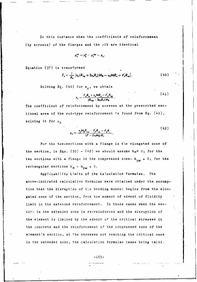
In this instance when the coefficients of reinforcement
(by screens) of the flanges and the rib are identical
Equation (37) is transformed
=.L 1C- (Rap + 2PAR+) bM -- pbhRe + F.Raci. (40)R,
Solving Eq. (40) for acs we obtain
FR, + I bhMR - r(, R(41)c (Rap.+_2peRc)bb.
The coefficient of reinforcement by screens at the prescribed sec-
tional area of the rod-type reinforcement is found from Eq. (hi),
solving it for Vc
a bh o17 . F R 1- F F42)(F - 2,cbhg) Re
For the tee-sections with a flange in tVe elongated zone of
the section, in Eqs. (30) - (42) we should assume hn= 0; for the
tee sections with a flange in the compressed zone- h = 0; for theyw
rectangular sections h. - hyW ,. 0.
Applicability Limits of the Calculaticn Formulas. The
above-indicated calculation formulas were obtained under the assump-
tion that the disruption of the bending momen" begins from the elon-
gated zone of the section, from the moment of advent of fluidity
limit in the extended reinforcement. In those cases when the sec-
tin,, in the extended zone is re-reinforced and the disruntion of
the element is limited by the advent of the critical stresses in
the concrete and the reinforcement of the compressed zone of the
element's section, at the stresses not reaching the critical ones
in the extended zone, the calculation formulas cease being valid.
-165-

The condition of the original development of the critical /144
stresses in the extended zone is expressed by the inequation known
from the ferroconcrete theory:
Sý _<.So,(43)
where St' - the static moment of area of compressed zone of section
relative to the axis running through the CG of sectional
area of the extended reinforcement;
So - the static moment of useful sectional area relative to
the same axis; and
- the coefficient depending on the type of concrete.
Th applicatlon of this condition to the sections with the
dispersed-type distribution of the reinforcement is made difficult,
since the position of the CG of the sectional area of the entire
extended reinforcement depends in its turn on the position of the
neutral axis, which complicates the calculation of the static
moments Sd' and So.
It is known that the maximum height of the compressed zone
will take place in a rectangular section in which the screen rein-
forcement is lacking. In this case, condition (43) yieids:
x<0,55&.
In the case when in the section, the rod reinforcement is
lacking and there are cnly screens, the maximum height of the com-
-pressed zone does not exceed x = 0.50 ho, since at a sufficiently
close approximation of the compressed zone to this limit, the
equilibrium of the internal strusses become impossible, while the
section of the screen reinforcement tends toward infinity. This is
indicative of the fact that at a large but finite reinforcement of
the section of the reinforced concrete element by some screens, the
-166-

height of the compressed zone will be slight.
For the upper limit of the height of the section's compres-
sed zone, determining the possibility of applicetion of the reduced
calculation formulas, one should adopt the least height of the com-
pressed zone of the section, obtained from the following two condi-
tions.
1. The height of the compressed zone of the section should
not exceed half of the useful height of the section
X 0,5Oh 0,50.
h, (44)
2. The static moment of the area of the compressed zone of
the section relative to the CG of the sectional area of the extended
rod reinforcement should not exceed a certain part of the static
moment of the useful sectional area relative to the same axis
s6 < "So./145
The value of the coefficient E for brand 400 concrete is
recommended to be assumed equal tc 0.80, while for brands 500 and
600 concrete, the value should be assumed at 0.70 and 0.65, respec-
tively.
For the tee-and double-tee sections, condition (43) is
equivalent to the condition
Ao -- AO, (45)"
where we determine the valueA* according to the formula
0
Ao•06,5±(bŽ h, h-(' ,-o.5Ž • (46)
b ho ho, ho
-.167-

Application of Formulas to the Solution of Certain Problems
on the Design of the Flexured Elements of Reinforced Concrete (in
the example of an element of a double-tee section). a. Verifying the
strength of the section. Give:n: the geometric characteristics of
the section, the areas of the reinforcement sections, mechanical
characteristics of materials, the bending moment, caused by the
external forces.
1. Find the coefficient of height E of section zone accord-
ing to Eq. (38).
2. Determine the characteristic A w:,t' . Eq. (32).
3. Find the bearing capacity of section M with Eq. (30).
4. The value of the moment based on Eq. (30) muct be greater
than the value of the moment from th: external forces.
b. Determining the sectional .rea -; •irnf)rcement. i-roblem
1. The concrete of the compressed zone of the section was fully
used, Ao = (Ao)np.
Given are the geometric characteristics of the section, the
reinforcement coefficient with screens, the mechanical character-
istics of the materials and the bending moment in the section.
The finding of the sectional area of the extended and com-
pressed rod-type reinforcement is conducted in the following sequence:
1. Assign as the critical value the characteristic Ao from
condition (45).
2. Find the characteristic Ao' from Eq. (35).
3. Find the coefficient & from Eq. (33).
4. Find the characteristic of the section ac from Eq.(39)
-168-

5. Determine the sectional area of the compressed rod
reinforcement with Eq. (36).
6. Determine the sectional area of the extended rod rein-
forcement with Eq. (40).
Problem 2. The concrete of the compressed zone was not
fully utilized, A0 np(
The compressed rod reinforcement is prescribed, or is im-
posed by the design concepts. In addition, we xnow the geometric
characteristics of the section, the coefficient of reinforcement /146
by screens, the mechanical characteristics cf the materials and
the bending moment in the section. The sectional area of the ex-
tended rod reinforcement is determined in the following order:
1. Determine the characteristic Ao' according to Eq. (31).
2. Find the coefficient ý based on Eq. (33).
3. Find the characteristic of the section ac from Eq. (39).
4. Determine the sectional area of extended rod reinforce-
ment according to Eq. (4o).
Problem 3. The concrete of the compressed zon.! of the section
was not fully utilized, Ao < (Ao)np.
Known are the geometric characteristics of the section, the
areas of the rod-type elongated and compressed reinforcement, the
mechanical characteristics of the materials, and the bending moment
in the section.
The sectional area of the screens' reinforcement or the
coefficient of reinforcement by screens is found in the following
order:
1. Determine the characteristic Ao' according to Eq. (31),
-169-

into which there is substituted the lease value Pc, determined
from the design concepts.
2. Find the coefficient & based on Eq. (33).
3. Determine the characteristic of section ac based on
Eq. (39).
4. Find the coefficient p c of reinforcement by screens based
on Eq. (42).
In the case when the PC-value found in this manner differs
markedly from the adopted for substitution into Eq. (31), it is
re-substituted into this same formula, and we find the refined
value for uP. Such a calculation by successive approximations,
the number of which as a rule does not exceed 3, leads to the ob-
tainment of i fairly close coincidence of the pe-values, calcula-
ted with Eq.(42) and adopted for the substitution into Eq. (31).
Calculation of Eccentrically Compressed and Eccentrically
Extended Elements. I. Case of Eccentric Compression. This is
typified by the fact that the disruption occurs at the attainment
of the cr-itical values of stresses in the reinforcement of the ex-
tended zone of the section. Owing to the high plastic deform&tions
associated with the onset of the phenomenon of fluidity in the
elongated reinforcement, there occurs an intensive opening of the
cracks, owing to which we have a decrease in the height of the con-
pressed zone of the section; as a result, we have the development of
critical stresses in the concrete and in the reinforcement of this
zone of the section.
-170-

The system of internal forces for the critical state in case
I of eccentric compression for an element with a section of any sym-
metrical form is shown in Fig. 79.
Writing an equation of the equilibrium of projections of in-
ternal forces in the section onto the element's axis, and the equation
for the moments of these forces relative to the CG of the sectional
area of the elongated rod-type reinforcement, after a number of /147.
transformations, we will arrive at the calculation dependences for
finding the bearing capacity of the section, and a determination of
the sectional area of any of the reinforcements. These dependences
are analogs of the Eqs. (23) - (29), typifying the critical state
during flexure.
The equation for finding the critical bearing capacity of the
sectionNe (2,,R, R.,) Abh- F.R.az- p.,FRez.
Fig. 79. Z•iagr--n of niternzal Forces in a Section for thecritical state in Case T o ecc:entric ccm~ression: a- geo-metric system of seto %b -systen cf internal stressesfor critical state-, and c - cnverted system of internalstresses for the critical state.
Ihe equaticn foýr finding the -hlaracteristic A
.N e &,F R c z 9 F @R ~ c z I
a.)., b )o • ,
-(48)
12/R R, -I

The equation linking the characteristic Ao with ac and y,
Ao = acY. (49)
The equation for finding the sectional area of the compressed
rod-type reinforcement
Fa R [Ne - (2pRc _- R,,) Aboh + 1g.FR~zI. (50)F sc (h R. - a')
The equation for finding the section area of the extended
(elongated) rod-type reinforcement
F [(-4,R .. R.,)•_Fbh9R- FaR.Fc - -RNI" (51)R, /148
The equation for finding the coefficient of reinforcement by
screens:bAoR, F'R, - F R, - N
(F - 2cbA.) R, 52
The equation for finding the characteristic of the section
•FRC -F.R --F.R . (53)•€ " (2.ýcRc R,,P) bN
\a c
a) b)
Fig. 80. Diagram of Internal Forces in a Double-Tee Section
for the Critical State in case I of Eccentric Compression:a - geometric diagram of scotics; b - diagram of internal stres-ses in rib; c - diagram of internal stresses in the over-hangs and widen'ngs; ani d - diagram cf internal stresses inthe rod-type reinforcement.
-172-

The diagram of the internal forces for the critical state in
case I of eccentric compression for an element of a double-tee section
is shown in Fig.80. The calculation dependences are derived from the
equations of equilibrium of intcrnal forces and moments.
The equation for finding the bearing capacity of the section
Ne =-R,, + -tC3R, ý(b: --b)(h - ().5h,,) h, p- 21&PR,,) A'bh '
+ FR.ýI,- 1 hj'Ib/zR (0.5h -a)-u'~(b,,,-- b) (O,5hyw - a) hywRc 54
'Ihe equation for finding the characteristic A0 ' and the co-
efficient t
A, ____- A'e - R, -, !,cR (b, - b)(/i0 - - (55).R, 2:AR bh- 5
-~F'R ih,-oa' -, ibhRc (0,5h -a) +± K~ (,c ,-b' jfl.5h,11, -,a) h) RC; (56)
i-I I-2A0 * (57)
/149
The equations linking the characteristics A0 and A,':
IN - ) (h - UW h(58)AD= A0 + Are (I - 0.5;) 4- - -b)A--O5~A
On A - b)~ ((59).hn
The 3ectional area of the compressed rod-type reilnforcement
F. ~ ~ - Ne R, ic R b - b) (h.e~ -- 0,5), hR,
-J C

The sectional area of the extended rod-type reinforcement
F, 1IRp + ? Rc)(b.-- bi ,, + iRnp + 2R,) (bh1 + (6i)+ N- pbhR, -- P- (bY= -- b) Rj
The coefficient of the height cf compressed zone of the sec-
tion:
E 'F.RL + 4-bhR, +iY`(bjo-b)h,.R + (2(,R ;, --!21-Rc) bho a CC6 '
-4 N - F;Ra, -- IRnp + LcR Rc)(b,- b)h/,,.
The expression for the characteristic of the section ac
at •+On=- ( b-- ) hn 163)bh2 +
(63)
In the case when the coefficients of reinforcement by screens
of the edgings (?) and of the rib are identical:
Equation (61) is transofrmed
F [-' + , F;R,, -- Nj. (64)R,=
Having solved Eq. (6') for ac, we obtain:
F R , bhR -- FRc A'_C (65)
The necessary coefficient of reinforcement by screens in case
of a prescribed reiniýrcement of the rod-type mounting is found from
a solution of Eq. (65) for L C
• ¢bh(R,,p F, R,, -- N - F, R,!1CF- 21, ý #)R, _ t)6)
In Eqs. (54) - (66), for the tee-1c1 nt sections with a /150
bord" in -Ahe compressed4 zone, we should assume hyuj = 0; for tnie
tee-joint se ,.I ns. r with a border in the extended zone, hn = C and,
-74-

finally, for the rectangular sections - h- a hy• = 0.
Since the stressed state in case I of eccentric compression
does not differ in its nature from the stressed state during tending,
all the limitations of the height of the compressed zone of the
section of the elements (which are being bent) are also extended to
case I of eccentric compression.
re, 46
4""
M N
Fig. 81. Diagram of Internal Forces in a Section for theCritical State During Case II of Eccentric Compression:a - geometric diagram of section; b - case when the disrup-tion starts from the edge closest to 'he force N; c - casewhen the breakdown begins from the edge more distant fromthe force N.
The design of the elements, extended eccentrically according
to case I, can be achieved according to the formulas presented for
case I of eccentric compression with the substitution into the design
formulas of the value for the standard strength N with an opp:site
sign.
I1. The case of eccentric compression is characterized by the
fact that the disruption takes place upon the attainment of the criti-
cal stresses in the reinforcement and concrete of the most compressed
sectional zone. The nature of the breakdown and the stressed state
resemble the critical state for the centrally compressed elements.
i -175-

In Fig. 81, we have shown a diagram of the internal forces for
the critical state in case II of eccentric compression for an element
with a section of any form, symmetrical relative to the flexure plane.
In the case of slight eccentricitie3, the breakdown can start
both on the side closest to the force N, applied with the eccentricity
e in relation to the CO of the sectional area as vell as on the side
more remote drom the force N, which will be determined both by the
configuration of the section as well as by the area0of reinforcements
F a and F' a. /151
The equatirn for the equilibrium of moments relative to the CG
of the sectional area Fa of the rod-type reinforcement more distant
from the standard force N, has the form
Ne D0 -D;J•z.- Daz.
The equilibrium equation for the moments relative to the CGof the xectional ares F' of the rodutype reinforcement located closer
a
to '.he standard force N, has the form:
We = +O6 + D e I z+D.z.
In these equations:
D; - FR.P. D6 zFR.,:
D. - pFR6 ; ?) , pFRe;
Do = FRo; Do - FR,.
Having substituted the value of the Internal forces and of the
arms into the equilibruim equation of the moments, aiud having solved
them relative to the force N, we will derive
N.m i(R.P+ R,aR)A~bi4+ FR..(h-a*)I; (671)N =-- [(R,v + p~e.) Aý'b' +. F;R, (ho '];(6Nu• ±(Ru, +p,)Ab.jF..(68)
-176-

where
;F ZbhQ h hQ3
Frow Eqs. (67) and (68), we can find the 3ection-1 areas of
the rod-type fittings (reinforcement):
U-
r•fiN,-(R R-j .c)A• .( OORa (he- a)
F.-M; - (RP -,,R) Apbh0R. (h,-' ) (70)
and also the necessary coefficient of reinforcement by screens, if
the sectional area of the rod reinforcement is already known:
,-- R,, Iho-(
Nr'- F•R, -al e__ (72)
The application of the formulas to the solution of certain
problems In the design of the eccentrically compressed elements made
of reinforced concrete (in the example of an element of a double-tee
section). Case I of eccentric compression.
a. Verification of sectional strength. /152
Given the geometric characteristics of the section, the sec-
tional area of the reinfornement, the mechanical characteristics of
materials, the external force in H and the eccentricity of its
application, e.
1. Find the coefficient & from Eq. (62).
2. Determine the characteristic A'. from Eq. (56).
3. Find the bearing capacity of the section from Eq. (54) and
compare it with the value of the moment, caused by the eccentrically
-377-

applied force, N.
b. Determination of sectional area of reinforcement. Problem 1.
The area of the concrete of the compressed z one of the section is
completely utilized, Ao = (Ao) n pGiven the geometric characteristics of the section, the
coefficient of reinforcing by screens, the mechanical characte-istics
of the materials, the force N and the eccentricity, e, of its appli-
cation.
The determination of the sectional area of the extended and
compressed rod-type reinforcement is conducted in the following order:
1. Assign the critical value of the characteristic A. from
the condition (45).
2. Find the value of the characteristic A'O from Eq. (59).
3. Determine the sectional area of the compressed rod-type
reinforcement from Eq. (60).
4. Find the coefficient & from Eq. (57).
5. Detezmine the section area of the extended rod-type rein-
forcement witn Eq. (61).
Problem 2. The area of the concrete in the compressed zone is
not fully utilized Ao < (A o)n
The section of the compressed rod-type reinforcement is given,
or is determined from the design concepts. We also know the geometric
characteristics of the section, the coefficient of reinforcement by
screens, the mechanical characteristics of the materials, the force N
and the eccentricity, Z, of its application.
We ascertain the sectional area of the extended rod-type rein-
forcement in the following sequence;
-178-

1. Find the characteristic A' from Eq. (55). /153
2. Find the coefficient t from Eq. (57).
3. Determine the sectional area of the extended rod-type
reinforcement from Eq. (61).
Problem 3. The concrete in the compressed zone of the sec-
tion is not fully utilized, Ao < (Ao)n Pt
We know the geometric charactcristics of the section, the
areas of the rod-type extended and compressed reinfcrcement, the mech-
anical characteristics of the materials, the force N and the eccen-
tricity e of its application.
The sectional area of reinforcing the screen, or the coeffic-
ient of reinforcement by screens is found in the following order:
1. Determine the characteristic A'0 from Eq. (55), into which
we substitute the least (from design concepts) value for pc"
2. Find the coefficient & f-om Eq. (57).
3. Determine the characteristic of section a c from Eq. (63).
4. Find the coefficient pc of reinforcement by screens from
Eq. (66).
If the value obtained for vc differs greatly from that adopted
for substitution into Eq. (55), it is substituted into the same formula,
and the calculation is repeated successively up to the obtainment of a*
sufficiently close coincidence of the vc-values, computed from Eq.(66)
and being applied for substitution into Eq. (55).
Case II of eccentric compression. a. Verifying the strength of
a section. Given the geometric characteristics of the section, the
sectional area of the reinforcement, the mechanical characteristics
-179-

of materials, the external force N, and the eccentricities, e and
e' of its application.
The verification of the bearing capacity of a section •educes
to a comparison of the least of the values of force N, yielded by
Eqs. 67 and 68, with the value N of the prescribed external force.
b. Determination of sectional area of reinforcement. Problem 1.
We know the geometric characteristics of the section of the element
the coefficient of reinforcement by screens, the mechanical charac-
teristics of the materials, the external force N, and the eccentrici-
ties of its application.
We determine the sectional areas of the compressed and extended
rod-type reinforcement from Eqs. 69 and 70, respectively.
Problem 2. We know the geometric characteristics of the element's
section, the sectional areas of the rod-type reinforcement, the mechani-
cal characteristics of the materials, the external force N, and the
eccentricity of its application.
We determine the required coefficient of raizi!orcement by
screens based on one of the Eqs. 71 or (2, yieldina the maEyirmum value.
Section 23. Results of Tests for the Strength of Sh~p Designs
Made of Reinforced Concrete
The effective utilization of reinforcel concrete in the shlk-
"designs is conditioned by tne reliability of our knowledge concerning
its behavior in the designs at various values aiud m-thods cf applying
a load, and also by the reliability of the all'ied methods of calcula-
ting the strength of the reinforced--concrete designs. Proceeding from
these concepts, for the purpose of obtaining experimental data concern-
ing the operating features of the ship reinforced ccncrete designs,
-18o-

we ran tests on the strength of several of them. In this connec-
tion, we incidentally investigated the influence of the systems of
reinforcement, the operational capability of the connecting elements,
and the effect of the manufacturing technology. /154
In connection with the fact that a large part of the designs
in the makeup of the ship's hul] functions for the absorption of the
bending loads, the basic attention was devoted to the question of the
investigation of the strength of the reinforced-concrete designs
during this type of loads.
Bending of Beams. The tests for the bending of the reinforced-
concrete plates, reinforced by ferroconcrete beams, from the viewpoint
of working out a method for the estimation of the strength of such
designs, the study of the influence of the reinforcement systems for
reinforced-concrete plates wc:re of primary interest.
2500 . -,,-°--.r--: -- 1S. ... i •i..,.W. '\ r, • _
i | - _--,rT-- O- Jl - - .
Fig. 82. Design of Ribbed Plates, Reinforced by OneStiffening Rib. Key: a) diameter 4, • t;,•,ing 100.
We subjected to the tests, the de;igns )f twc types the piates
reinforced by one rib (six designs of tne Ly,,y sbowr in Fýg° b2) and
the plates reinforced by two ribs for -tif1fe.-InF (three design- of
the type show,, in Fig.83).

For the production of the designs, we used sandy concrete,
brand 400 on a base of sulfate-resistant Portland-cement, brand 500
with a composition (by weight) cement: sand: water = 1:2:0.36. The
mobility of the concrete mixture corresponded to 5-6 cm of the set-
tling of the cone used as a standard by the Stroy-TSNIL. The designs
were reinforced by mesh-type steel screens (GOST 2826-47) and hoý-rolled "
rod-type reinforcement (GOST 502-41).
The system for the reinforcement of the plates in the first
type of design had three variants:
- reinforcement by ten mesh-type screens No. 8 with a diameter
of 0.7, equally distributed through the thickness of the plates;
- the reinforcement of the intermediate welded mesh of rods
with a diameter of 4 mm, located in th!. center of the plate's thick-
ness, and with six webbed screens No. 8, diameter 0.7, with a fixed
arrangement of three screens from each side of the intermediate rod-
type screen; and
- the combined reinforcement similar to the previous case, with
the placement of the screens one on the other without assembly tension,
but with bonding into a bundle of binding wire. /155
The reinforcement of the plates in the second type of designs,
and the reinforcements of the beams strengthening the plates are shown
in Fig. 84. The concreting of the designs was conducted in the wood-
metal forms with the rib downward, with utilization of type 1-7 sur-
face electric vibrators for packing the concrete. The anchoring of
the ferroconcrete rib with the reinforced-concrete plate was accomplish-
ed by installing the lug of the clamps of the reinforcing frame of the
rib between the half-packets of the webbed screens of the plate. All
-182-

Fig. 83. Design of Ribbed Plates Reinforced by TwoStiffening Ribs. a) diameter 6, spacing 100; andb) clamp, diameter 6, spacing 100.
of the designs were tested in a condition when the reinforced-con-
crete plate was placed in the extended zone. The load was applied
according to the system of pure bending, in stages of 1/10 - 1/15
of the breakd1wn Ioad. At each stage of increasing the load, we
measured the linear deformations and the sags, established the ap-
pearance of visible cracks, and we measured the width of their open-
irng. The nature of the disrupticn of all the designs was identical /156
and corresponded to the following pattern.
T7ne furmation of the cracks started on the upper surface of
the plates; then they penetrated the entire thickness of the plates
and proceeded further into the extended (stretched) zone of the beams,

P=fr
ios i
Fi. 4.Disteribto of Stress eys Acrs Widtry ofi of
beam section.
reinforcing the plates. Under a further load of the designs, in the
zones of the effect of the shearing forces, there appeared sloping
" cracks along the beams' walls. The width of opeiing of these cracks
immediately reached 0.10 mm. The final rupture of the designs took
place as a result of the breakdown of the compressed zone of the beams,
concret~e. By this time, the width of cracks' opening on the upper
surface of the plate constituted 0.15-0.20 mm. We failed to observe
ruptures in the webbed screens of the reinforzed-concrete plates.
-184-

We succeeded in utilizing the results gained from measuring
the linear stresses across the plates' width for the approximate de-
termination of the value of the attached strip of the sheathing, par-
ticipating Jointly in the beam's functioning. We have indicated in
Fig. 84 the distribution curves of the deformation across the widti of
the plates for different values of the loads based on the results ob-
tained from testing the first type of designs. As is evident from
the graph, the di3tribution of the stresses across the plates' -.ith
under all loads depends on the system of reinforcing the plates for
those which are reinforced only by the webbed screens with Kn = 2.2
cm2 /cm 3 , we typically find a more uniform distribution of stresses
by width than for the plates with the combined reinforcement having
a specific reinforcement surface K = 1.7 cm 2 /cm 3 .
Equating the area of the actual distribution curve of the stres-
ses and the fictitious rectangular curve to the side, tantamount to
a deformation in the plate directly over the beam, we determined the
value of the attached strap. In the cases which are under considera-
tion, the width of the attached str&p comprised 92 cm ("pure" reinforced
concrete) and 84 cm (combined system of reinforcing the pýate), which
exceeded by 35-25% the third part of the design span of the beams
during the tests, and by 50-40% the twe,ty-fivefold actual thickness
of the reinforced concrete plates. It is evident that the recommenda- 1157
tions, generally adopted in the ferroconcrete shipbuilding, relative
to the design width of a plate, functioning together with a beam,
with application to reirforced concrete require e-me refinements.
For a Jud# •r. 2' ',he values of the loads at which the width
of the cracks' o., r. :. ; the reinforced concrete plates constituted
-185-

0.05 mm, and for a comparison of them with the calculated values, we
have presented the data corresponding to the tests of the second type
of designs:
Values of bending moments (ton-meters), correspondingto an opening of the cracks in the elongated zone byabout 0.05 mm:
from the experiment .......... ......... 4.17by calculation ......................... 4.75
Ratio of the values of the bending moment,obtained by the experimental ard calculationmethod, % ................................ 88
The calculated value of the bending moment was determined on
the basis of the method of disruptive loads, proceeding from the fol-
loving assumptions: the uniform distribution of the forces through
the thickness of the plate and the operation of the plate's material
with the entire area of the section, to axial elongation. The adoption
of these assumptions is substantiated by the nature of the deformation
of the designs, expressed in the process of the tests.
The fairly close coincidence of the experimental and design
values of the bending moment permitted us to recommend the calcuiation
of designs, representing the combination of beams made of ferroconcrete
and plates of slight thickness made of reinforced concrete, based on
the prir.clple of the method of breaking loads. In this context, in the
case when the plate is located on the side of the extended zone of the
section,the value of the breaking force and the value of the arm of
the internal couple should be determined, proceeding from the reduced
area of the plate and the standard resistance of the plate's material
to axial elongation, adopting the curve of the stresses in the compressed
zone of the beams according to a triangle (since at the moment of the
-186-

cracks' opening in the plate by = 0.05 mm, as the experiments have
shown, the equivalent compressing forces do not exceed 50% of its
critical value). One should not take into account in the calculation
the functioning of the concrete in the beams to elongation.
8ending of flat plates. The purposeful object of these tests
was the obtainment of data on the strength of the monolithic reinforced
concrete plates and the checking of the operating capability of the
connection points of the reinforced concrete plates with each other
and of Lhe reluforced concrete plates with the ferroconcrete ones in
one plane. The monolithic and jointed plates were subjected to the
tests. All of the plates had the same dimensions in plan of 1500X1000
mm; the thickness of the plates and the systems of their reinforcement
were different. /158
The connection of the reinforced concrete plates with each
other and of the reinforced concrete plates with the ferroconcrete
plates in one plane was zonducted on a bypass without the welding of
the reinforcement rods (the length of bypass was 75-80 mm) of the con-
necting plates, at simultaneous bypAss into the zone of joining of the
webbed screens. The design of the connecting reinforced concrete plates
with the ferroconcrete ones corresponded to one of the variants of the
design of plates of the 'tweendeck of the hulls on the ferroconcrete
marine ships. The thickness of the ferroconcrete plates equalled 60 mm;
the plates were reinforced with two screens from rods with a diameter
of 6 am.
The reinforced concrete plates were made from sandy concrete
of the planned 500 brand. The consumption of materials per cubic meter
-187-

of cement-Gandy concrete comprised:
Portland-cement, sulfate-resistant, C, kg 810Sand, S, kg ................................. 1200Water, W, liters .............................. 290Water-cement ratio, W/C ..................... 0.36
The quality of the materials having been utilized for the
preparation of the concrete complied with the requirements of the
effective State Standards (GOST) for the building materials.
The data concerning the dimensions, system of reinforcement,
strength of concrete, and number of tested plates are presented in
Table 13.
The testing of all of the flat plates, jointed and monolithic,
was conducted according to the system of pure bending. The load was
applied in steps, equalling 0.20 of the calculated breaking load.
The duration of the delay tetween the individual stages com-
prised 5-10 minutes. During the delp.y, we measured the stresses, the
bendings (sags) of the plates and the width of opening of the visible
cracks. The breakdown of the plates took rlace from the side of the
elongated zone in the action span of the maximum bending moient. The
rupture of the extreme webbed screen in the elongated zone, as th,
final result of breakdovn, was preceded by the formation and opening
of cracks In the elongated surface of the Indicated section of the
plate.
The cracks' formaticn c:curred at value.s -f reltatve i ve a-
tion stresses not exceeding the values c - - >?"' Under a
further lotd. the opening of the cracks vhi:z had formed was te~sycd
owing to the increased adhesion of the reinforcement anr the :cncrete,
caused Ly the large surface of tte vebted icreens, and ihe increase In
the stresses tcck Flace Thiefly o0ing to the fcrusticn -f the new

00
Hr d 4
4.)0 2 i
0
011 -1*0
A N
U .
0.4
.0 189-

cracks in such a way that in the action zone of the constant bending
moment (M = const), the cracks up to the time of their opening by
0.05 mm were arranged with a spacing of 2-3 cm.
The strength of the reinforced plates in the flooring of the
'twaendecks and the plates of the hull ceilings of marine ships is
sufficient (Table 14). /160
Table 14
Values of the Bending Moments Obtained by an Experimental andCalculation Method and also in Effect in Analogous Ship DesignsBased on the Design Materials ( by Groups of Plates).
9,-v- IVauerofbw~n 0-Valued of Ptiod
jfor group e I Beti at1n O, 1 to Oxacu 4 m2t 13ý Rboniing no,!d design. spisg in olm~te6a~ M&I Imssqimnt nets ob-
by 0.05 no O 746- 10u6s of
--fro based on ui ations mmmwtsto 8 cin
enPermsi4 tt asdancl ertinet(design) qlmn SiP de
11.1 0,116 0,142 0,05 82 2,311-2 0,783 0.740 - 106r1-3 0,256 0,335 - 76 --n1-4 0,433 0460 - 94 -
rIC- 1 0,116 0,145 0,03 80 3.8S fC-2 0,116 0,142 - 82 -
Ibingk. The aelculated wilus. of the beIntn sments vere de-temin scooouting to the instr-ations at tbs 'ntativs Rasa foroCon&uotung tie Itrength Wolatiame of &ip Desi, ' anfocmd
. The observed deviation in the experimental data toward the
lower direction as compared with the calculation data can be ascrijed
to the increase in the thicknesses of the protective layer of the
designs as compared with the planned thicknesses. The indicated
-190-

increase in the thicknesses of the protective layer is caused by
the fact that all of the tested experimental designs had only plus
deviations in respect to thickness, having reached 10-20o of the plan-
ned values of the plates' thicknesses, and at the same time, accord-
ing to the adopted procedure for producing the designs, under which
the webbed screens are previously combined into a bundle, the height
planned design thickness.
The design of the connection in one plane of the reinforced
concrete plates with one another, and of the reinforced concrete
plates with the ferroconcrete ones, with the aid of a bypass without
the welding of the reinforcing rods of the intermediate screens, and
a bypass into the Juncture zone of the webbed screens, provides in
the Juncture zone of the bending flat plates the crack resistance and
strength which is equivalent to that in the flat (plane) monolithic
plates. However, after the appearance of the first cracks, their /161
subsequent opening (considerably larger) and the breakdown of the
Jointed reinforced concrete plates during bending took place along
the sections of the termination of the bypass zone of the reinforcing
rods of the intermediate screen. This is evidently explained by the
fact that during the loads causeing the formation of cracks ini the
elongated zone of the bending plates, there took place the disruption
in the adhesion of the reinforcing rods with the concrete. The attempt
to simplify the technology (abandonment of the welding of the projec-
tions of the intermediate screen) and to reduce the width of the Joint
to the minimal dimensions (reduction in the length of the bypass of
the rods of the intermediate screen) was not reflected on the crack
-191-

resistance of the jointed plates as compared with the monolithic
ones (refer to table 14). However, in the case of the bending of
jointed plates, reinforced by beams, when the plate will be situated
under conditions of elongation over the entire section, the indica-
ted design of joints can not guarantee the crack resistance and
strength, equivalent to that of the monolithic designs. For the
reliable functioning of the connection of the sections in the designs
of the indicated type, it is mandatory to weld the projections of the
reinforcing rod in the Junction zone.
Testing the reinforced concrete plates for compression. In
connection with the fact that the reinforced concrete designs are the
most thin-walled ferroconcrete designs, considerable interest for the
practice was represented by the question of the effect of the flexibili-
ty of the reinforced concrete plates upon their bearing capacity during
central compression.
We subjected to tests the plates with dimensions of 700 X 500 X 25
mm. The reinforcement of the plates consisted of ( 3+3) webbed screens
No. 10, with a diameter of 1.0 mm and of an intermediate welded screen
of rods with a diameter of 5 mm at a spacing of 100 mm. The plates
were made from the cement-sandy concrete having the composition:
* Portland-cement, brand 500, kg ...... 750
Sand, kg .................... ....... 1350
Water, liters............... . . . . .. 260
Based on the data from the tests of the control samples up to
the time of testing the plates, the strength of the concrete comprised
i10 kg/cm2 .
-192-

The testing of the reinforced concrete plates for centralcompression vas conducted under the hinged support of the short edges
of the plates, which was attained by the utilization of special head-
ers, with the consideration of which the calculated length of the
plates comprised 750 mm. During the testing, the load distributed
along the short 3dges of the plates was applied in stages. At each
stage of loading, we measured the linear deformations of the plates
with sensors (pickup devices) for resistance and we also used mech-
anical comparing devices.
It was established during the process of the tests that from
the very beginning of loading the plates, their compression was accom-
panied by bending, in spite of the fact that they did not have, for
practical purposes, an initial camber (round). Evidently this is ex- /162
plained by the dissimilar structure of the reinforced concrete through
the thickness of the plates.
In the utilization of the combined system of reinforcement, the
heterogeneity of the reinforced concrete structure. is inevitable in
the sense that the longitudinal rods of the intermediate welded screen
are not located in the central plane of the plate. The heterogeneity.
caused by the displacement of the vebbed screens depends on the method
adopted for producing the plates. The breakdown of the plates took
place suddenly wvthout the preliminary appearancP of perceptible
stresses or sags, and represented a brittle fracture, characterized by
the pressing out of the concrete and by the crushing of the bared screens
from the side of the most stressed edge, with the subsequent frac-
ture of the screens on the opposing side.
-193-
4*p

The breakdown load, according to the average data from the
testing of three plates, comprised 24.0 tons; according to the cal-
culation without allowance for the flexibility, it was 41.5 tons;
based on the calculation with allowance for felexibility equalling
for the tested plates io/b = 30, the value of the critical load = 20.8
tons. The nearness of the values of the breakdown load based on the
dets from the tests, and of the critical load, with consideration of
the plate's flexibility, oonfirms the need for taking into account
the flexibility of the elements of the reinforced concrete designs
operating under compression.
Section 24. Substantiation of the Standards of theDangerous and Permissible Stresses for the Marine
Reinforced Concrete Designs
In distinction from ordinary ferroconcrete, in the used of
which in shipbuilding considerable experience has also been accumula-
ted, reinforced concrete does not have any finished theory of ade-
quately broad practice of allication. Therefore, the Justified
standards for the reserve of strength for the marine reinforced con-
crete designs under the varying conditions of their loading have not
yet been finally developed at the present time.
However, the planning and the construction of experimental
ships made of reinforced concrete are impossible without specifying
the standards for the strength reserve. In their development, we have
tuken into consideration the operating conditions of the designs in
the makeu, of a ship hull, and the features of reinforced concrete as
a building material. The reinforced concrete, as a variant of ferro-
_-194- I.

concrete, under elongation and compression, has differing valLes of
the characteristics, corresponding to the beginning of the structural
modifications of the material.
The process of the formation of cracks in reinforced concrete
during elongation and bending depends appreciably on the type of
reinforcement: of the dispersed (by webbed screens only) or combined
(vebbed screens and rods). /163".
Even before the complete exhaustion of the strength, we find
an abrupt increase in the lengthening of the cracks, with an intensive
increase in their ,Tidth of opening. The ratio of the stresses, cor-
responding to this state of the reinforced concrete, to the strength
limit, cstablished by the strength of the reinforcing frame, is all
the higher, the higher the brand of concrete and the extent of dis-
persity of reinforcement, i.e., the higher the K n.
The method for the calculation of the reinforced concrete
marine designs, if we tentatively regard reinforced concrete as a
homogeneous material, under the validity of the hypothesis of plane
section for the elements with cracks in the extended zone is actually
the calculation of the resistance to cracks.
The results of calculating the bearing capacity of the rein-
forced concrete elements, close to the experimental data, are obtained
in the calculation based on the method of the breakdovn loads.
In the reinforced concrete designs, by nature thin-walled, the
protective layer is measured only in several milimeters,and the ques-
tion of shielding the wire reinforcement having a large surface acquuir-
*a unique urgency, especially since the process of corrosion can cause
the flaking and collapse of the protective layer of concrete, and the
complete exposure of the reinforcement.
-195-

In this manner, based on the conditions of the corrosive strength
of the reinforcement screens and the water impenetrability, the marine
reinforced concrete designs are identical to the construction designs
of the first and second category of crack resistance, in which during
operation the visible cracks are not permitted. Therefore, as the
dangerous stresses during elongation (axial and during flexure), for
-the ship designs made of reinforced concrete, we adopt the stresses
corresponding to the width of cracks' opening of 0.01-0.05 am at a
thickness of the protective layer in the design comprising 2 mm. The
dangerous stresses during compression and compression during bending
are assumed equal to the prismatic strength of the cement-sandy con-
crete, i.e. without allowance for the screens located in the compressed
zone of the section.
The values of the standard (dangerous) resistances of reinforced
concrete are listed in the Appendix. For the permissible stresses, we
assume a certain fraction of the standard resistances.
The strength standards for the ship designs made of reinforced
concrete are specified to be such that in the transition to the strength
limit of the material, the values of the reserve coefficients of
strength in respect to breakdown are obtained as not below those es-
tablished by the Rules for the Construction of Ferroconcrete Ships
fssued by the River Registry of the RSFSR and the Registry of the USSR.
In the conversion of the values of the reserve coefficients to the
standards of the permissible stresses, wc took into consideration the
relation between the stresses, corrisponding to the moment of cracks'
opening by 0.01-0.05 an, and the streigth limit (according to the
experimental data for shipbuilding reinforced concrete, equalling j0.70-0.75).
-196-

/1164Chapter V. STATIC TESTS OF THE STRENGTH OF
REINFORCED CONCRETE HULL OF A FLOATING CRANE
Section 25. Purpose and Problems Involved In the Tests.
The pontoon driftwood-hoisting crane with a hull made of rein-
forced concrete (the characteristics of the hull design is given in
Chapter 2) is the first and as yet the sole, not counting the small
ships of sporting design, reinforced concrete ship in the practice
of domestic (Soviet) shipbuilding. Prior -o the lowering of the hull
into the water, on the slipvay of the dock, we conducted the static
tests of the general strength of the hull, and the local strength of
the section of the deck flooring. Taking into account that the intro-
duction of reinforced concrete into the practice of ferroconcrete ship-
building is inseparably linked with the requirement for refining the
physical concepts concerning the functioning of the reinforced concrete
designs of a ship hull and the consequent improvement of them, prior
to the strength tests of the reinforced concrete hull, the problem was
raised both of a purely research nature, as well as of a direct evalua-
tion of the hull strength and of its individual units, the propriety
and feasibility of the actual solutions, having found reflection in
the process or planning the hull. Under the static tests for the
strength, the following questions were solved:
1. The experimental checking of the overall hull strength during'
buckling and camber (hogging), of the local strength of the deck floor-.
Ing section, and also the detection of the flaws in the hull-type de-
signs.
2. A determination of the dependence V -c in the basic longi-
tudinal connections of the bull (sheathing of the deck and bottom)
-197-

70.
VI .8 .3 1;, 5 9
. ~ ~ W *h' ;7 IFin 'ri -J'5.%
5. I dlL%
Is %
Fig. 85. Testing a hull for overail strength; a -system
of arranging the supports sAlorng the length o~f hull and ofsections for measuring the bet-ding deflections.
a - mobile supports;*- section of Installing the gag measuring devices;
b - loads acting on the hull; c - curves of th~e oendingmoments eau transverse forces In~ the .iull prior La the be-ginning of the tests; d - curvts of the bending moment* andof the transverse forces during the camber of the hull (finalstage); e - the same, during sagging of the hull (final stage).

during the general bending.
3. A determination of the elastic lines of the ship hull during
I its testing for buckling and camber (hogging).
Section 26. Procedure used for Conducting the Tes4 s
The tests cf the overall longitudinal strength were conducted
by placing 'he hull onto four supports (Fig.85,a). The distance be-
tween the supports along the length of the hull was chosen from the
condition of a uniform distribution of the hull weight on each support /165
in the position of the hull adopted during the tests for the zero
position, and under the assumption that the hull weight corresponds /166
to that planned.
As the central supports, situtated in the sections along the
12th and 22nd actual frames (ribs), we utilized the building slip
carts with hydraulic Jacks having a lifting capacity of 60 tons. The
terminal supports located in the sections along the 4th and 26th frames
were stationary and represented the building slip carts and wooden
cages.
The tests conducted on the overall longitudinal strength in-
cluded the tests for camber and sagging. The bending moment was created
owing to the actual weight of the hull by way of a graduated lifting or
lowezing of the central supports. At the time of the occurrence of
hull only on the central supports, we determine the weight of the hull,
which proved to equal 135 tons. The weight of the hull determined by
weighing exceeded its planned value, corresponding to the saturation
of the hull at the time of conducting the tests, by 29 tons. Taking
into account that the excess weight of the hull was caused by the in-
accuracy of the concreting, the amount of this overweight can be related
-199-

only to two items in the weight load: the hull and the superstructure
(each of which is made of reinforced concrete).
Multiplying the ordinates of the indicated items of the weight
load, carresponding to the planning data, times the coefficient found
.as the ratio of the weight of the hull and superstructure with allow-
ance for the excess weight, to their weight based on the design data,
we will derive new values of the ordinates for these items of the
weight load.
In this manner, introducing the new ordinates for the indicatd
items and having taken into consideration that all the other items of
the weight load of the ship remained unchanged, we vill obtain a dis-
tribution of the weights over the hull .'en6 i during the conduct of
the tests (Fig. 85 b).
The value of the load absorbed by each of the central supports
was determined by multiplying the pressures in the cylinders times
the area of the plunger in th 1:.ftirg jacks of the building slip carts.
Under the known values of the reactive forces of the central supports
P., the reactions of the outermost supports for each stage of loading1
was determined from the equatirn of moments realative to each of the
stationary supports, if we consider the hull as a beam,lying on them
M MVPI 0;
_M.= M Al 0
where EM = the bending moment from the actual weight of the hull(the hull weight within the limits of each theoretical
frame spacing is distributed uniformly according to
Fig. 96, b);
-200-

EMp4 the bending moment from the reactive forces of the
central supports; /167
MR1,MP2 a the bending moments from the unknown reactive
force of one stationary support relative to the other.
The values of the reactions of the stationary R1 , R2 and of
the mobile Pi supports by stages of load are given in Table 15. Tne
nature of the change in the bending moments and in the transverse
forces over the length of the hull is indicated in Fig. 85, c,d,e.
Table 15
Values of Reactions (Tons) of Supports by Degreesof Loading
,FAOt6 Ls AW.O 1 .Pon- 11balg __s _
1 P 6 13 2 24 129 34 3 4
a 22 P:' 6 11 20 24 2 34 138 24 3 69.
The values of the bending moments, calculated from the position
assumed during the tests for the zero position, in the %sections of
installing the measuring instruments by degrees of loading are indi-
cated in Table 16.
-201-
i. 2lJ' I'2 '4234 3

Table 16
Values of the Bending Moments (Ton-meters) in the HullSections, Corresponding to the Places of Installing theMeasuring Instruments During the Testing of a Hull for
Overall Strength
5 4 , 3 2 1 o I -2 3 4I .di.d.,
S-120- 8.37 115.5 -2,, 1 S. 3 ' 3 202
/168
To the tests for local strength, we subjected the section of
the deck flooring situated between the 4th and 7th frames, and also
between the right side and the second longitudinal bulkhead. An evenly
distributed load was created by spreading sand on the tested section
of the deck, vherein the intensity of this load was increased in stages
in the following sequence: 0.14; 0.30; 0.43 and 0.60 tons/m2 .
The bending moments for the under-deck beam in the span between
the longitudinal bulkheads, established by calculating the rib frame,
are presented in Table 17.
The bending moments for the plate of the deck (the latter is
regarded as a nonsectiinal beam-strip with a width of 1.0 m) are pre-
sented in Table 18.
-202-
iI

Table 17
Values of the Bending Moments in the Upper Branch ofthe Rib Frame Between the Longitudinal Bulkheads
from Local Loading
mint Sm.i--ins -___
Ot 4K *fum. X fm G106 -I
insswi swmC
7 1 0 I
II 0210 0.294 0.160 -0,171Iii 0.305 0,401 0,219 -0,233IV I 0420 0 306 -0.317
Table 18
Values of Bending Moments in the Deck Plate LoalLoad
'~1g~d inyA_D" at o In ut Im a *Mtn
I 0,098 0. 0 G 12 0,00312I 1 0,210 0.0152 6,00667 --0,(130
II I 0,305 0,0221 0,00%9 -0,006 2IV 014020 1" 305 0.,0134 - .• , !
The loading of the hull was done by stages during the tests.
After each of them, a delay was made of 10-15 minutes, necessary for
the stabilization of the stress-strain stete of the hull. Under the /169
effect of the maximal bending moments, the hull vab kept for one hour.
A203-

At each stage of the loading, during the testing of the overull
and local hull strength, ve measured the linear deformations of the
hull connections (joints), we determined the elastic line of the hull
during general bending, and we measured the pressure of liquid in
the plungers of the building slip carts.
The measurement of the linear deformations during the general
bending of the hull was conducted with comparators, which were instal-
led on the bottom and deck in the section between the l1th and 12th
frames during boggri and in the section between the l1th and 15th
frames during sagging.
Under the arrangement of the devices, in addition to the value
of the effective bending moment, we took into account also the remote-
ness of the section from the region of the abrupt changes in the form
of a transvirse section, caused by the presence of the superstructure
and the notch of the hull.
During the tests of the strength of the deck to bending, by
local loading, the linear deformations were measured by tensometers
of the Gugenberger type which were mounted half-way along the length
of the side of the support edge of the plate parallel to the short
side. In the checking of the strength of the deck beams during bending
by local load, the comparators measuring the linear stresses were in-
stalled in the central and in the outer sections of the beam span paral-
lel to the beam's axis.
The measurement of the sagging deflections during the static
tests of the hull was conducted in five different sections, coinciding
with the arrangement of the transverse bulkheads, which excluded the
possibility of the deformation of the hull sections under the load in
-2o4-
1-_

the process of testing. The depths of camber were measured by the
sag measuring devices of the Maksimov system, fastened to the sta-
tionary designs, not connected w'th the hull, along each of the
sides. The system of arranging the sag measuring devices along the
length of the hull is indicated in Fig. 86, a. For determining the
reactive forces transmitted to the hull by the mobile supports, the
pressure in the hydraulic jacks of the building slip carts was measur-
ed carefully with calibrated manometers.
Section 27. Results Obtaine4 from the Tests
In the inspection of the hull prior to the tests, we established
that certain beams in the deck are non-coaxial (up to 40 mm) with the
ribs of the sides and the longitudinal bulkheads. In addition, the
beams of the framing had chipped-off places and nonconcreted areas.
In the sections of the bottom and joints of the plates, there projected
for 15-30 mm the coverings and excrescences of concrete. In a number
of places, the 1.rotective concrete layer above the webbed screens was
lacking. /170
In the testing of the hull for sagging, the maximal bending
moment equalled 113 ton-meters, while in testing the hull for camber
(hogging), it was 185 ton-meters (i1g. 86,e), which exceeded by 4.38
and 1.70 times respectively the calculated bending moments for the
foot end crest of the wave.
The results obtained from measuring the linear deformations
and saggins of the hull (Tables 19,20,21), and also the behavior of
the hull in the process of the tests indicate that the design of the
hull, eyen in the presence of the above-enumerated defects, caused by
-205-
L

F~0V
10
4##
bd ot hl - cp t 2 0- coaI
tr 161. Ke:a o, tosmees.4 t
Fig. $6. Dependence of the load-deformations for theplates in the deck and bottom during the overallbending of the hull. X - comparator 21; 0- compara-tors 16,17. Key: a) M, tons-meters.
the disruptions in the construction process, provided a monolithic
state of the hull and the participation of all of its essential mem-
bers in absorbing the loads acting on the hull. No cracks or any
other visible damages to the hull in the process of the tests were
recorded.
The relationship curve M - c for the plates of the deck and
the bottom during the overall bending in indicated in Fig. Ot,. In /172
Fig. 87, we have indicated the curves of the variation in the sag-
gings of the hull in a position on the two central supports during
camber ad of the two outer supports during sagging under the effect
_____ ____ -206--- _ _

o NOT REPRODUCIBLE
-4•
E- -- • .0_ _ _ _
bo
4- (\j 4' 8
4, - I 4-
0. 0 .
-4 ,,
-207-

of its own weight. The corstruction of the elastic lines was made
from a po.3ition assumed to be the zero one.
J.. . ... _________________
Fig. 87. Line of the hull saggings during general bending:
a b,c - 2,3, 4- degrees of camber; d,(t,f,g,h - 1-5 degreesof sagging3.
The calculation of the stresses in the hull members under theeffect of the test loads was conducted with allowance for a certain
thickening in the sheathing plates as compared with the planned thick-
nesses, owing to the inaccuracies In the concreting; specifically,
as the design values of the sheathing thickness for the plates of
the bottom, sides and deck, we adopted the vz.lue of 26.5 mm, while
for the bulkhead plates, we assumed 21.0 mm. The variation in the
Table 21
Readings of the Sagging Meters (cm) During the OverallBending of the Hull
rI,, wt o*,,r,, .. .... ..
to n.nO -1-Gi -'lq --.(I p lo it*. f ti.ft 1 -i .u- rI. V''.4 2f?(2 -¢.• 41 i}W i l 1q r, } ? (.l ' " r.J t:
S 16 .0. o9 -- v ( - oil o •rtA I ' r,I ()ft. (,I] ". ft r',,' 1 )3 O.(V -K!2 - V' 119" 31 n~ r~'6 "?2 - 079 I ., -
~k Tesow rea&I12a~g a the in..truniats coroiopood~ to the@toot, att"@ of The U (fl5 84. a). NOT REPRODUCIBLE

1/173
linear stresses in the extreme fibels of the equivalent beam
(of the deck and bottom plates) during the overall bending of the hull
can be estimated with sufficient accuracy by straight lines (see
Fig. 8 6 ). In this connection, the linear deformations in the compres-
sed'and elongated zones are almost equivalent, and do not exceed the
abablute values (10 - 20) 10-5. Based on what has been said, "An
a c-l:ulation of the stresses in the hull members, we can nssume as
identical or very close the values for the moduli of the extended
(elongated) ind compressed zones of the tr&nsverse section of the
hull. The values of the stresses in the hull during overall bending,
obtained as a result of calculation under the above-mentioned assump-
tions, are presented in Table 22. All the reinforced concrete elements
were introduced into the calculation with there own reduced area, i.e.
with allowance for the additional reinforcement of these elements of
the reinforcing rods. The reduction factor of the rod (extended and
compressed) reinforcement to the reinforced concrete n a 10.
Table 22
Values of Stresses in the Plates of the Deck and Bottom (atthe Level of Installing the Comparators) from tho Overall
Bending of the Hull
A 1. 1 Z4 138. -2Z 1 1P-I 1-61? - 7.2- .II - 120
1,80 5.65 9.83 15.2 -2.2-,50 -7.90- 8.8941 15,
S -2,02I-6.3-11,1-17.0 2.73 6.32 7.55 a.6s 14.8-2 4.74 6.r2 7.71 0.2
ne J1 -7 . Z . 0. -
-209-

a.
The very slight stresses from the overall bending of the hull
are quite regular, if we take into account that the thickne~s of the
sheathing for the small ships is specified on the basis of the condi-
tions providing local strength, and not a general strength; moreover,
"in the planning of a hull for a pontoon crane, the sheathing thickness
was specified not from a calculation of the stressed state, but from
a design standpoint, for the purpose of increasing the resistance to
impact.
The suggestion concerning the diversity in the elasticity moduli4
for the elongated and compressed zones of the section leads to a re-
distribution of stresses in the following manner: the elongatiou /174
stresses diiainish, while the compression stresses increase as con-
pared vith the stresses determined under the assumption of the iden-
tical values of E and E . At the ratio E /E 1.5 adopted.ofP. •p
in nux calculation, the indicated redistribution of stresses is quite
insignificant.
3 i.' a3.-
io I
a
Fg.88.Stress-etraIn diagram for the plates in the decY andbottom during the overall bending of the hull. *- deck piate;X - bottom plate. Key: a) kg/c. 2
-___ __ __ _-_ _ __ _

The curve a-c, constructed on the basis of the data in
Tables 22 and 19 is shown in Fig. 88. The values of the stresses
in the sub-deck beam from the bending by the local load, calculated
under similar assumptions are presented in Tthle 23. Table 24 shove
the values of the stresses in a deck plate from the bending by a
local load, determined from the formula oa M/W.
The calculated values of the saggings of a ship hull diring
overall longitudinal. bending were also determined with consideration
for the increase in the dimensions of the cross section of the hull
members, caused by the inaccuracy of the concreting. In this con-
nection, we assumed that all the hull members were situated in the
stage of the elastic functioning of the concrete, when cracks were
lacking.
A comparison of the values of the saggings having taken place
during the process of the tests in the final stages, with the calcul-
lated values of the saggings for these positions of the hull (obtain-
ed when proceeding, on the one hand, rcm the value of the reduced
modulus for sagging E t 100,000 kg/cm2 and, on the other hand from"Ap
the reduced stiffness cf the cross Rectiou of the hull at E /E .
1.50) indicates their fairly close approximation and undoubtedly
confirms the acceptability of the formulas from structural mechanics
in a determination ef the deformations (saggings) of the reinforced
concrete designs.
An saalysis of the procedure used and the results obtained
from the tests of the overall strengtb of a pontoon crane hull made
of rrinforcod concrete, and also of the local strength of the sec-
tion of the deck flooring permitted us to make the following con-
! -211-
-q

I
clusions.
I1. The overall. longitudinal hulls strength, and also the local
strength of thie section of deck covering under the effect of loads
developed during the tests were fully provided.
Table 23
Values of Stresses in the Sub-deck Beam from the Bendingby a Local Load
kters.ot Intezasityof Ste.-olosIag rminwig ioamd .in rib In atx~rLA r ack OP (i placo .(in pla oe of
(mr 20o 3 or1) __
So,8.55 16,8'2i8 -8 12,2.'--:3,97.95
II 0.210 2"'.7 19.2 34.2 52.5 -32.0'--36.5Ill ~0. 30.r 28,2.'26.2 46,671:.6 -4 ,,-5•,IV 0,420 39.2.,36.3 63.4,97,3 -- 61,2/--69.3
lbmm*- Dibr in mmrator~ebi rto' •culwfAm&%1dpt.,- 'ioel values of slati, .d1 for oa remd A elm• Ipto
saw of8t io 16 g.%./•.r. ; mbn• in damminta r-fo to Calmlati-- at ,,i• values df slMUsHY• 2MW
fo aqreseeo & eloate& swaea of esctimi / u15.
?able 24
Values of Stresses in a Deck Plate from Bending by aLocal Load
keg tensilgjvr Ct abiss. kg/=arumnn~in~ 02 p I in ..otiK of alms the
baa ta~ .m sat io. ~ -0iS11a th e oter of_______ tore _________ the
10,098 6 .09 2.66 1 ,16811 0.210 13.0 ,5)36
111 0,305 18,8 8,19 s.22Z
IIt

2. The conformity of the results obtained from measuring the
hull saggings during the overall bending with the calculated data /175
according to the determination of the displacements of the hull in
the process of the tests based on the formulas from structural mech-
anics during the application of the reduced elastic modulus in re-
spect to the sagging E - 100,000 kg/cm2 and of the reduced stiffnessrp
of the hull should be regarded as a known confirmation of the accept-
ability of the methods, recommended by the Provisional Rules' for the
calculated estimation of the deformations (saggings) of the rein-
forced concrete designs.
3. The results of the 'sts according to the determination of
the relative linear deformations and stresses are of slight interest,
which is explained by the very low quantity of data and small values
of the stresses and strains, having taken place in the hull during
the general bending.
-213-

APPENDIX
Provisional Rules for the Conduct of Calculations of the Strengthof Ship Designs Made of Reinforced Concrete
1. GENERAL CO1,CEPTS
1. The Present Rules apply to the ship designs, made of cement-sandy con-
crete and reinforced steel screens or steel screens and reinforcing rod, in accord-
ance with the instructions in Sections II and V.
2. We should consider as reinforced concrete designs the dispersed-rein-
forced designs on a base of cement-sandy concrete having a specific reinforcing
surface K >/ . cm2 /cm 3 .
3. In the reinforced concrete designs, there is pernitted an additional
reinforcement of the extended (elongated) zones by reinforcing rods.
4. The designs of slight thickness, reinforced by steel screens and rein-
forcement rods having K< 2 cm2 /cm3, in the practice are also tentatively said to
be of a reinforced-concrete nature. The instruction on the calculation of such
designs is given in section ?3 of the Present Rules.
I1. MATERIALS
A. Concrete
5. For the production of the reinforced concrete designs, we should use
the heavy cement-sandy concrete, brand 400 and higher.
Remark. The brand of concrete is adopted tentatively and is typified by
the strength limit (kg/cm2 ) for the compression of a concrete cube, with an edge
of 7 cm, made from a concrete of working composition and tested after an aging of
28 days, in accordance vith the standard ON9.373-62.
6. For the obtainment of the shipbuilding reinforcement concrete, wo should
apply Portland-cement, of a brand not lover than 500, of the folloving typese a)
conventional; b) plasticized; and c) sulfate-resistant
.214-.

The enumerated types of Portland cements should meet the requiroeents of
GMT (State Standards) 970.41 and of the branch standard O.9.374.62 "concrete,
shipbuilding, heavy, Mlaterials for the production of concrete".
7. For the preparation of cement.sandy concrete, we should utilize the
natural sands, meeting the requirements of the branch standard ON9.374.62 with
the screening out of the grains coarser than 2.5 mm,.
8. The water for preparing the concrete mixture should meet the require-
ments of the branch standard W09-374-62.
B. Reinforcement
9. For the reinforcement of the reinforced-concrete designs, we utilise
the steel screens and the steel low-carbon wire.
10. The webbed steel screens should meet the technical specifications
imposed by GOMT 3826-47.
/17711. The recommended numbers of screens (meshes) and their specifications
are presented in Table 25.
Table 25
Characteristics of the Recommended Webbed Screens
lea- •" 'ie k t '&A _ - I si I&ei43q1 give. VWeqa Ib j
___ K I e[." tdaa& tl -m•=
-S en m --- f-d'la"
5 0.7 350 0.770 0.0072* 0.7 300.660 0.057
7 0.7 n0 0.572 0.00M00* 0,7 239 0.306 0.006439 .0 no0 0.57 0.0075tO .0 ISO 0..5;0 O.O0•lS
.215.
|

11. The steel low-carbon wire utilized for the additional reinforcement
of the extended tons of the reinforced concrete designs and for replacing parts
of1 the webbed screen according to the engineering concepts (see Section 35, 36)
should meet the requirements of GOST 3282 ':,
III, STANDARD CHARACTERISTICS
12. The elastic-strength characteristics of reinforcing concrete on a
base of concrete brand 400, reinforced by steel screens and having a specific re-
inforcement surface K. 2 cm2 /cm3 are adopted according to Table 26.
Table 116
Standard Characteristics of Reinforcing Concrete
*Wp of strasmse @1W 1= k/m
..... . . Rp = 66 £p - 50000.i o . . ... . . R, - 320 Et = 200000
ZlaaMIb da begug. . RP., a 120 EP.= 50000COIRWIm 0 m .. U. Rc.,W" M320 EC. -. 150000M 1 .......... Re,,w 65
.. ............. Rcv'- I0O
13. The magnitudes of the valies of the standard resistances and the elas- /178
ticity moduli of the cament-sand concrete, reinforced by a small number of webbed
screens vtth 0.5< X "< 2.0 cg2 /cm3 (in this connection, in all cases the nmber
of screens is not less than 2), are adopted in conformity with the instructions
in Table 27.
14. The coefficient of the relative transverse deformtion of reinforced
concrete (the Poisson coefficlenti•• assumed to equal v - 0.12.
The shear modulus of reinforced concrete Is determined from the formula
CG 0.45 Cc.
-216.

Table 27
Standard Characteristics of Cement-.andy ConcreteReinforced by a Few Webbed Screens
Msse. k#/=3 zowv. iit
.. __....... RP = 20 n - 25' O re/ mfe" as. ....... . . . . R e R = 320 E,€ 200 000MamSpl/as &win bwtn&..I RV,. 35 X, 4 EP. _-3e0M
• p ~ e/ a w .. . ,j R e. , $I al 3 0 E ,. m . 5 O0 000
IV. BASIC DEM I GN CONICEPTS A41D STIGTH STANDARDS
15. The calculation of the design stren.:t sh'r•:l ndicate that for it,
there Is assured the required strength reserve, I.e. under the effect of the ex.
ternal design forces,, the stresses in the design do not exceed the tolerable values,
16, The volume of the strength calculations# represented In the engineering
plan is mtablished by the Registry of the USSR, by the River Registry of the MSFSR,
or by the buyer in dependence on the type and purpose of ship. In a general case,
there should be presentezz
a) A composite table of the veights of the hull and of the variable cargos.
distributed through 20 theoretical compartments, vith a brief explanatory listing
of the procedure used in compiling this tables
b) An Instruction on the loading of the ships
€) The calculations on determininx the bending moments and the transverse
fore"s I
d) Calculation of general strengths
a) Calculations of local strengths and
f) Detailed Instructions on the "odifled Standards or on the specification
of the Standards not envisaged by the existing Rules.
17. The calculation of Strength, In a general case, IS subdivided I0co
the following Individual par•se
.21?.

a) A determination of the value and nature of the design loads;
b) A determination of the maximum stresses in the design sections for
the adopted design loads; and
c) The specification of the values of the hasardous stresses, the estab-
lishment of the standards of tolerable stresses and a verification of the strength,
18. The calculations should be accessible for an exhaustive verification
of all of the data included in them based on the design materials and based on the
references to the sources.
19. The external design loadsp acting on the ship hull and on its Indi-
vidual parts are established in accordance with the instructions of the effec.
tive standard documents of the USSR Registry, or of the RSFSR River Registry,
with allowance for the requiresents of the technical project for the planning
and section 20 of the present Rules./179 4
20. The actual hull weight is determined on the basis of the measurements,
adopted in the plan, for the mombers of its designs.
The volumetric weight of the reinforced concrete is found fron the for.
mule lags =lu* T '1F Il.
where P- the reinforcement factor of the cemont-sandy concrete in one direction;
end -f.6 a the volumetric weight of the cement-sandy concrete determined experimen.
tally in each Instance. In the absence of experimental data, in the preliminary
calculations, we have decided to assume - 2.20 touw.m 3 .
21. The values of thse stress*@ developing In the reinforced concrete de-
sign during the effect of the design load on It, are established according to the
general rules of the structural ship mechanicy under the assumption that all the
ship material Is Isotropic and under the effect of the design leods functions as
elastic material. In this context, the caeculation of the designs for bending is
.21 R.

conducted with allowance for the difference In the values of the elastic
characteristics for the comqpressed and extended (elongated) sones.
22. The reinforced concrete designs# reinforced additionally by rode#
are, calculated according to the elastic stage of the functioning of the rein-
forced concrete according to the Instruction of the existing Rules, with allow.
isnce for the reduced section of the element (member), The reduced section of the
mesber io determined proceeding from the relationship of the standard resistance
of reinforced concrete and the calculated (designed) resistance of the rod-type,
reinforcement; In this connection, the design resistances of the reinforcement
rod for all types of steel are assumed to be:
for the reinforcement of the extended elements Rap kglcm?....1200
f or the reinforcement situated In the extended sones ofthe bending elements Ra, kg/cm2 .............................. 2400
The rod-t"p reinforcement located In the compressed sone, of the section of
reinforced concrete design Is not considered In the calculation,
23. The calculation of the sections reinforced by a small rumber of steel
screaM with 0. 5 < K~ "(2.0 cm2/cm3, Is cood-acted In the sae way &A the calcula.
tion of the reinforced concrete seCtious. In this connection, the values of the
standard resistances Itt are determined on the basis of Taible 27, while tie* design
resistanceO of the rod-type reinforcement for all types of steel are determined
frau Table 28 depending on the value of the coefficient of specific reinforcemernt
surface, K ,1.
For the Intermediate values of K. ,, the values of the design resistances
of the rod-type reinforcement are determined by linear interpolation,
24. for the danigers (standard) stresses during elongation and elonga. /186
ti~n durin$ beMndin, we adopt the stresses corresponding to the asmnn of opening
of cracks by the smunt of 0.01 M, at a thickngess of the Protective layer of 2 ons
.219.

during the compression and compression under bending, we adopt the stresses
equalling the prismatic strength of the cement-sandy concrete,
Table 28
Design Resistances of Rod.Type Reinforcement Utilised for
Reinforcing the Reinforced Concrete Designs
odd dm I •
dlts ow~ d baft" I
2.0 I 200 24001 ,5'0 1900
1.0 I 700 140010.5 450 900
The standard resistances of the material on a base of cement-masdy con-
creteo reinforced by webbed steel screenw, are determined according to the in.
structions in section I11,
25. The permissible stresses are specified as a certain fraction of the
standard resistances according to tho instructious in Table 29,
Table 29
Standards of Permissible Stresses NOT REPRODUCIBZZ
-..-... , o-0.0UM J 0.O75 0.51-
fed--,1 0.3 M0.•I[ oMo o I I0.65 o.u 0.16
The str•enth of the design Is constderet to be guarenteed if the total
effectiwe stresses do not surpass the values of the permissible (tolerable) stresses.
.220.

In this connection, if by the calculation for the simultaneous effect of
the constant and random forces, or by the calculation for the emergency loads,
there is provided the required strength reserve (see Table 29)d It Is necessary
that under the effect of only the constant forces, there would be assured the
strength reserves not lower than those indicated in this table.
26. In the necessary cases, in addition to verifying the strength of the
design in respect to strf'aeeB, we should verify the stability both of the entire
design as a wholep as veil of its individual m ers, and also we should verify
the maximum stresses.*.
Q ', 27. The compressed elenents during the flexibility Io/r c 30 (iv' stability
Ure not verified, In the calculation of the compressed elements for stability at
the flexibility la/r ) 5Y (for the rectangular section )o/b > 14), the permissible
stress to coamresison is lecreasod by multiplying It times the coefficient of long.
itudinal bending,
16 14 1 104 lo 0.J.4 1 O.U I0tO 1 0.4642. t 0.* 117 34 0.44so 30 0.73 1i1 5 0.4070 3 0,07 131 1 0.3743 14 0.* 137 40 O.s0 a 0. 7 144 41 0.1W I 0.5 1ir 44 0Jo
RenSrk. At the intermediate values Iotr or Io/b, the qL.values Are adopted
by linear interpolation,
The design length of the element 1 is obtained by the multiplication of
its actual leaxth times the coefficient, depending an the method of reinforcing
(attaching) the ends. The coefficient has the folloinx valuest
durins the rixlJ fastenin.t of the ends................0.5
durini the hinged fasteninX of both ed.............,l.O
In case of one rixidly fastened and onef leI bty.faestened end...., ............. e.g..... 0,7
in case of nes ri•i.dly fastened and theroth.. freely.o.unted end ......... .. ............ 2.0
-221.

in case of the partial fastenin4 of the
ends and In the frames witlý non.displacing units......O.,
in the frame" with displcing wtI0*t,,....,,...... 1.0.1.5
28, The verification of the maximum stresses of the bending elements
should be conducted on the basis of the formulas from the ship structural mech.
antcs, procoeding from the actual geometric di-ensions cf the design and of the
reduced elasticity modulus P for sagging, or from the reduced stiffness of
the element, taking into account the difference in the elasticity moduli of the
elongated and compressed sonee and the inertial moments of these sones.
The values of the reduced elasticity for bending, grip for the loads$
not exceeding the maximal operational loads under the conditiones
brief (transient) effect of load 9rjp, ks/cu2 .... o...20200000
prolonged effect of load, 9 "py kg/cu2 ,...e..e.......l0V 000
The maximal sagging must not exceed 1/300 of the value for the designed
s pan,.
29. The combined desigsz, representing a combination of the bea made
of ordinary ;erroconcrate and the plates of slight thickness, reinforced by the
webbed steel screens, and also with scres and Individual rods. should be cal.
culoted on the basis of the principal of the method for the breakdown leods,
30. In a determination of the value of the breaking load in dependence on
what part of the section (compressed or elongated) the plate is located, we should
distinguish two casess
a) If the plate is located in the section's Cmpressed Sone., the breaking
force it determined as for the toe.type beam made of ordinary ferrconcrete, with-
out allowance for the webbed screens of the pistol
b) If the plate to located in Wb elongated sons of the section, the
breaking force is established proceding from the reduced area of the plato and
the value of the standard resistance ot the waterial, guided by the instriuctions
.222.

in sections 12, 13, 22, and 23 of the present Rules. In this contexts we
overlook the functioning of the concrete in the beam tv elongation, while
the elongated reinforcement of the beam is introduced into the calculation
with the stress equalling the desigr resistance R. of the re-nfo-cemit.
31. The design width of the plate, functioning together with the bea",
is assumed to equal the least of the following valuess one third of tV'e desigi
spat- of the beam; the half-sum of the plate's spans adjoining the beam; or 25
times the thickness of the plate.
32. The strength of the combined designs Is regarded as assured$ if the
coefficients of strength reserve obtained as the ratio of the design breaking
force to the desIgn force from the effective load, do not surp. as the norres-
ponding values, governed by the existing Rules for the construction of ferro-
concrete ships, while the crack-resistance of rhe beam in the elongated zone
of the section complies with the requirements of these same Rules, /182
V, IlM5TRUCTIU FOR DMIGNING
33. The thickness of the designs made of ,-ment-sandy concrete reinfor-
ced by steel screens is adopted according to calculations but Is not le•s -_ha:
10 in,
34, The thin-walled designs made of cement-sandy concrece should be re.
inforcsd by the steel gauze screens in order that the specific surface of the
reinforcement would fall within the limits of 2 .0,< O$ 4, 3.0 1/cm.
35. The steel screens should be distributed evenly through the height of
the design section.
According to the sn.•ineering concepts, it is permitted, in the central
third of the section height of the bending eleoents, to conduct the replacement
ot the fiber (mesh) screens by rods, and to leave the standard specffications of
the mter.al without change.
.223.

36, The rod.type reinforcement introduced into the calculation should
be situated between the mesh screens; moreover# from the side of the protective
layer of the elongated zone there should be not less than two mesh screens.
The diameter of the reinforcing wire is established depending on the
element's thickness, and should not exceed 5 mm.
37, The thickness of the protective layer in the designs under all
forms of reinforcement, Independently of the size of the specific reinforcement
surface, must equal 2 mm.
38. The joininr of the mesh screens in the elements should be conducted
with lao joints, with an overlapping of the ends by not less than 10 c",. The
joints of one layer of the screen should be displaced relative to the joints of
the other layers in order that in any section of the elmentj, there would not be
nore Ltan one Joint.
39. The projections of the rod reinforcement utilized for connecting the
beans with the plates and for attaching the inserted parts, should be introduced
between the mesh screens of the plates for a length of not less than 40 diameters.
40. The joiVts of the sectional (prefabricated) members are envisaged by
the plan. The design of the joints should not disrupt the strength or the water-
tightness of the design as a unit. In the connection of the reinforced-concrete
plates# it is necessary to provide for the bypassing (overlapping) of the mesh
screenp into the zone of the Joint.
41. For purposes of providing the corrosion resistance of the designs made
of cement-sandy concretep reinforced by steel mesh screens with a protective layer
of concrete equallir.g 2 mm, in tho required cases, one should envisagee the appli-
cation of protective coatings to the surface of the design; the application of mesh
screens with an anticorrosive coating; and the introduction of Inhibitors Into the
concrete,
.224.
--- m-r .---- -- . - -- -

BIBLIOGRAPHY
[1] Amel'yanovich, K.K., Antipov, V.A., Lapin, Ye.I., and Sintsov,G.M.: Features of Estimation of Strength of Ship Designsof Prestressed Concrete and Reinforced Cozucrete. Sudostrcy-eniye (Shipbuilding) No. 12, 1964.
[2] Amel'yanovich, K.K., and Verbitskiy, V.D.: Reinforced Concrete--Shipbuilding Material. Sudostroyeniye, No. 12, 1964.
[3] Akhverdov, I.N., and Luksha, L.K.: Steel-reinforced Concretewith Spatially Dispersed Reinforcement and Possibilities ofIts Application. In the collection: "Reinforced Concrete andReinforced Concrete Designs", Gosstroyizdat, 1962.
(4] Beletskiy, V.F.: Reinforced Concrete Instead of Wood. Stroitel'(Builder), No. 2, 1960.
[5] Biryukovich, K.L., Biryukovich, Yu.L., and Biryukovich,D.B.:Small Ships Made of Glass Concrete and Reinforced Concrete.Sudostroyeniye, 1965.
[6] Borovskiy, N.V.: Investigation of Off-Center Compressed Rein-forced Concrete Elements. In the collec.: "Reinforced Concreteand Reinforced Concrete Designs", Gosstroyizdat, 1962.
[7] Borovskiy, N.V.: Estimating Reinforced Concrete Designs forStrength. Stroitel'stvo i ArkhitekturL (Construction andArchitecture), No. 2, 1962.
(8] Borovskiy, N.V. and Nogin, S.I.: Investigating the Processesof Crack Formation in Reinforced Concrete. Beton i Zhelezo-beton (Concrete and Ferro-concrete), No. 9, 1961.
[9] Vasilenko, O.V., Mironov, B.A., and Suslikov, I.P.: New Thin-Walled Designs. Reinforced Concrete. Gosstroyizdat, 1961.
(10] Gamov, L.I.: Reinforced Concrete and Reinforced Concrete De-signs. Kartya Moldovenyaske, 1961.
(11] Gastey, V.A., Grodskiy, Ye.Ya., and Balavadre, V.K.: ReinforcedConcrete and Its Advantages Over Conventional Ferro-Concrete,No. 9, 1961.
[12] Clan, I.Ya.: Flying Rock. Izobretatel' I Ratsionalizator (In-ventor and Efficiency Expert), No. 7, 1962.
(133 Gorenshteyn, B.V., and Abovykiy, V.P.: Thin-Walled Ferro-Con-crete Shells with a Span of 75 H1eters at the KrasnoyarskPlant for Synthetic Fiber. Concrete and Ferro-Concrete,No. 11, 1959.
-225-

[14] Grodskiy, Ye.Ya.: Reinforced Concrete Designs for Rural Con-struction. In the Collec.: "Reinforced Concrete and Rein-forced Concrete Designs", Gosstroyizdat, 1962.
[15] Yevdokimov, V.D., Lobanov, I.A., and Mitrofanov, Ye.N.: Mech-anized Production of Reinforced Concrete Spatial Designs.Construction and Architecture of Leningrad, No. 4, 1961.
[16] Karmelyuk, N.S.: Application of Reinforced Concrete Designsin Water-Conducting and Hydraulic Structures. In thecollec.:"Reinforced Concrete and Reinforced Concrete De-signs", Gosstroyizdat, 1962.
(17] Klimov, 1.I.: Ways for Mechanizing and Automating the Pro-duction of Reinforced Concrete and Combined Desigrs. Inthe collec.: "Reinforced Concrete and Reinforced ConcreteDesigns", Gosstroyizdat, 1962.
[18] Kudrin, B.A., and Gryaznov, P.T.: Strength, Susceptibility toStrein, and Crack Resistance of Reinforced Concrete Pre-pared by Guniting. Izv. Vysshikh Uchebnykh Zavedeniy (Bull.of Advanced Schools), Construction and Architecture, No. 5,196o.
(19] Kudryavtsev, A.A.: On the Question of the Impact Strength ofReinforced Concrete and Thin Ferro-concrete Plates. In thecollec.: "Reinforced Concrete and Reinforced Concrete Designs",published by editors of Journal: "Bulletin of TechnicalInformation", Glavleningradstroya, 1959.
(20] Kurbayov, L.G.: In What Designs Is Reinforced Concrete MoreEffective? Construction and Architecture of Leningrad, No 5,1964.
[21) Lysenko, Ye.F.: Studies Caused by Deformations of Shrinkage andCreep of Reinforced Concrete. In the collec.: "ReinforcedConcrete and Reinforced Concrete Designs", Gosstroyizdat,1962.
[221 Kironov, V.I., and Bogoyavlenskiy, L.P.: Construction and Test-ing of the Frame of a Common-Hoisting Crane with a LiftingCapacity of 10 Tons. Shipbuilding, No. 12, 1964.
(23) Nitrofanov, Ye.N.: Mechanical Properties of Reinforced Concrete.In the collec.: "Reinforced Concrete Spatial Designt',Gosstroyihdat, 1961.
[24) Mitrofanov, Ye.N.: Application of Reinfcrced Concrete in Thin-Walled Spatial Designs. Publ. of LDETP, 1960.
-226-
_________________________________________

(25] Iitrofanov, Ye.N.: Problems Involved in Producing and Util-izing Reinforced Concrete. Features of the Material. Con-struction and Architecture of Leningrad, No. 7, 1961.
[26) Mitrofanov, Ye.N.: Functioning of Reinforced Concrete inDesigns. Publ. of LDNTP, 1961.
[27) Mikhaylov, N.V.: Basic Principles of New Technology of Con-crete and Ferro-concrete. Oosstroyizdat, 1961.
(281 Nervi, P.L.: To Build Properly (Ways for Developing Ferro-concrete Designs). Gosstroyisdat, 1956.
(29) lervi, P.L.: ZvoAution of Perro-concrete Designs. In thecollec.: "Thin-walled Designs", Gosstfoyizdat, 1963.
[30) Protopopov, V.3.: Experimental Study of Impact Strength ofReinforced Concrete Platings. TranS. of Oorky Institute ofEngineering Vattr Transport, No. 45, 1962.
[3:1 Rebinder, P.A.: liv Technology or Dispdrsed-Type Materials(Certain Applications or Physico-Chehical Mechanics). Vest-nih Akad, laut 8553 (16rald of USSR Academy of Sciences),No. 8, l96a.
[321 lNothr; AA., hid Frolov, l.A.: Rbintoied Concrete Yacht"Drias" ("Nfehtam). 8hipbuildingi Voe 6, 1966.
[33i Rodoi, G.S., an& Savoyskiy; V.N., Inweitigation of Prcpertiesof Fiber lets Used for the heiatobr*6ent of Reinforced Con-crete Designi. Trans. of Vestekn Siberian Branch of AS and Aof USSR, No. 5, 1961.
[34] Rudenko, Yd. I.: Reinforcel Concrete Tanks. Stroitel; (Builder),No. 5, 1961.
[35) Savinov, O.., Lavrinoviehi Ye.V.i and Tsukerman, N.Ya.: Cn.-tribution to the Question of the Rlibforcement of Thin-Walledrerro-Cotcrete Designs. In the co'lec.: "Steric (Spatial)Designs in the USSR". Stroyis4at, 196k.
(36) Saaoylov, B.I.: Calculation of Eltients of Reinforced ConcreteDesigns ana of Ferro-Covicrete Designs with Distnrbed Rein-foreement. Publ. of Kuybyshev Ingineering-Constuction Incti-tute, 196k.
(37) Frolov, I.A., and Reyner, AlI.: Yachts made of ReinforcedCcncrete. Shipbuilding, No. 30, 1963.
"-227-

[38] Khaydukov, G.K., Illarionova, L.F., and Kagaaovskiy, Ye.Ye.:Sectional Steric Designs Made of Reinforced Concrete Ele-ments. Concrete and Ferro-Concrete, No. 1, 1904.
[391 Khaydukov, G.K., and Milyavskiy, V.D.: On the Functioaing ofReinforced Concrete under Tension. Concrete and Ferio-Con-crete, No. 12, 1961.
[40] Tsintsadze, G.A.: Technique of Production (Withou'. Falsevork)of Spatial Designs. Concrete and Ferro-Concrete, No. 9, 1961.
[11] Shanshiyev, A.K.: Technique of Producing '.he Reinforced Con-crete Curved-Formed Steric Designs. Ii tk-e collec.: "Rein-forced Concrete and Reinforced Concrete Designs", Gosstroyk-zdat, 1962.
[42] Yunin, V.P: Investigating the Effect of Various Patterns ofReinforcement on the Strength Ch~racterlstics of Shipbuild-ing Reinforced Concrete. Trans. f-f 3orky Inst. o" Eng.Water Transport, No. 45, 1962.
[430 Collen, L.D.: Some Experiments iD Design and Construction vithFerro-3ement. Trans. of Inst. of Civil Engineers of Ireland,
Vol. 86, p. 40.
[441 Concrete Cruiser for France. Shipbuilding and Shipping Record,
Vol. 102, No. 11, p. 356, 1963.
[45] Concrete-Hull Craft. Shipbuilding and Shipping Record, Vol. 100,No. 23, pp. 733-734, 1962.
(46] Haunard, J.A.: Sea-going Concrete. Australian Seacraft Meg.,Vol. 32, No. 2, pp. 28-30, 1964.
['7] Nervi, P.L.: Precast Concrete Offers Nev Possibilities forShell Structures. The Jnurnal o£ the American Concrete Insti-tute, Vol. 24, wi.6, pp.537-548, 1953.
148] lervi, P.L.: Small Craft Construction in Ferro-Ceseet. Ship-building and Shipping Record, Vcl. 80, So. 12, 1956.
(k9] Nervi, P.L.: Ferro-Cement in Building ConstructIc. TheBuilder, Vol. 192, No. 5939, p.153, 1957.
(50o Reinforced Cement-Mortar Construction (Ferro-Cement). Concrettand Constructional Engineering, Vol. 56, go. 12, pp. 429-L33,1961.
1511 Scovino, 0.L.: Use of Reinforced Concrete in Building Naval51 hps. The Italian Cement Industry, 35, 5 2, pr. 191-200,1965.
-228-I*l

(52] Sporting Boats with Concrete Hulls [in German]. Schiffbautechnik,IiI, Vol. 13, pp. 163-164, 1963.
[533 Success of Concrete Boats. World Fih-ing, No. 1, pp. 6 -7, 1965.
(541 Thir Reinforced Concrete Members Form Turin Exhibition Halls.Civil Engireers, Vol. 21. No. 1, pp. 26-31, 1951.
[553 Thir.-jhell Reinforced Concrete in the United Kingdom. EnginLer-i:g, Vol. 195, No. 5051, py. 232-233, 1963.
-229-