SMP 300 Series • Setup Guide -...
10
1 This guide provides instructions to setup and operate the SMP 300 Series models. In this guide, the term “SMP models” refer to the SMP 351 and SMP 352 models. The Extron SMP 300 Series models are Streaming Media Processors, high definition recording and streaming devices for professional AV systems. The SMP models record MP4 files of one or two video channels with mixed audio, a PNG background file, and metadata in various layouts (composite mode). The SMP 352 models support an additional encoding mode, which records independent MP4 files of the two video channels with mixed audio in full screen (Dual Channel mode ), but without background image or metadata overlay. All SMP models support independent live streaming videos for archive and confidence, at different resolutions and bitrates. Any SMP 351 can be upgraded to SMP 352 by applying a Dual Recording LinkLicense. In addition to Dual Channel encoding, the LinkLicense also unlocks advanced audio DSP capabilities for level control, filtering, and compression. The SMP models fit in presentation recording, lecture capture, and enterprise training applications. Mounting The SMP 300 Series models are housed in a 1U high, full rack width metal enclosure that can sit on a table with the provided rubber feet or can be mounted using the attached rack mounts. Select a suitable mounting location, then choose an appropriate mounting option. Before connecting the SMP 300 Series models, turn off all devices that will be connected and then make all external device connections to the SMP models before applying power to the devices. Rear Panel Overview 100-240V --A MAX USB STORAGE LAN 3 B-Y R-Y VID /Y L R LOOP THRU INPUTS-CH A INPUTS-CH B OUTPUTS SMP 300 SERIES G REMOTE MOUSE / 100-240V --A MAX 50-60 Hz USB STORAGE RESET LAN 1 3 B-Y R-Y VID /Y 5 4 HDMI 3G/HD/SDI HDMI HDMI AUDIO L R L R LOOP THRU 2 INPUTS-CH A INPUTS-CH B OUTPUTS SMP 300 SERIES 1 2 3 4 G DIGITAL I/O Tx Rx RS-232 G REMOTE AUDIO L R AUDIO L R MOUSE / KEYBOARD 1 2 L M N O P Q A C D E F G H I J K B Figure 1. SMP 300 Series Model Rear Panel A 100-240 VAC IEC connector for power input J (Optional input 5) 3G/HD/SDI input card B USB type A receptacle for external storage device K 3.5 mm, 5-pole captive screw connector for channel B analog stereo audio input C (2) USB type A receptacles for mouse and keyboard L HDMI loop thru from input 1 or 2 D 3.5 mm, 5-pole captive screw connector for digital I/O M 3.5 mm, 5-pole captive screw connector for channel A analog stereo audio loop output E 3.5 mm, 3-pole captive screw connector for Simple Instruction Set (SIS™) control over RS-232 N HDMI preview output F HDMI inputs 1 and 2 O 3.5 mm, 5-pole captive screw connector for analog stereo audio output G 3.5 mm, 5-pole captive screw connector for channel A analog stereo audio input P Reset button and LED H 3 BNC connectors for component or composite video input 3 Q RJ-45 Ethernet connector for LAN connection I HDMI input 4 SMP 300 Series • Setup Guide Power Connection A 100-240 VAC power input — Connect the provided IEC cord. Verify the front panel buttons and LCD illuminate (see Front Panel Features on page 3).
Transcript of SMP 300 Series • Setup Guide -...

1
This guide provides instructions to setup and operate the SMP 300 Series models. In this guide, the term “SMP models” refer to the SMP 351 and SMP 352 models.
The Extron SMP 300 Series models are Streaming Media Processors, high definition recording and streaming devices for professional AV systems. The SMP models record MP4 files of one or two video channels with mixed audio, a PNG background file, and metadata in various layouts (composite mode). The SMP 352 models support an additional encoding mode, which records independent MP4 files of the two video channels with mixed audio in full screen (Dual Channel mode ), but without background image or metadata overlay. All SMP models support independent live streaming videos for archive and confidence, at different resolutions and bitrates. Any SMP 351 can be upgraded to SMP 352 by applying a Dual Recording LinkLicense. In addition to Dual Channel encoding, the LinkLicense also unlocks advanced audio DSP capabilities for level control, filtering, and compression. The SMP models fit in presentation recording, lecture capture, and enterprise training applications.
MountingThe SMP 300 Series models are housed in a 1U high, full rack width metal enclosure that can sit on a table with the provided rubber feet or can be mounted using the attached rack mounts. Select a suitable mounting location, then choose an appropriate mounting option. Before connecting the SMP 300 Series models, turn off all devices that will be connected and then make all external device connections to the SMP models before applying power to the devices.
Rear Panel Overview
100-240V --A MAX
50-60 Hz
USB STORAGE
LAN
3B-Y
R-Y VID/Y
5
3G/HD/SDI
AUDIO
R
L R
LOOP THRU
INP
UT
S-C
H A
INP
UT
S-C
H B
OUTPUTS SMP 300 SERIES
RS-232
G
REMOTE
MOUSE / KEYBOARD
1
100-240V --A MAX
50-60 Hz
USB STORAGE RESET
LAN1
3B-Y
R-Y VID/Y
5
4
HDMI
3G/HD/SDI
HDMI
HDMI
AUDIO
L R
L R
LOOP THRU
2
INP
UT
S-C
H A
INP
UT
S-C
H B
OUTPUTS SMP 300 SERIES
1 2 3 4 G
DIGITAL I/O
Tx Rx
RS-232
G
REMOTE
AUDIOL R AUDIOL R
MOUSE / KEYBOARD
1
2
L M N O P Q
A C D E F G H I J KB
Figure 1. SMP 300 Series Model Rear Panel
A 100-240 VAC IEC connector for power input J (Optional input 5) 3G/HD/SDI input card
B USB type A receptacle for external storage device K 3.5 mm, 5-pole captive screw connector for channel B analog stereo audio input
C (2) USB type A receptacles for mouse and keyboard L HDMI loop thru from input 1 or 2
D 3.5 mm, 5-pole captive screw connector for digital I/O M 3.5 mm, 5-pole captive screw connector for channel A analog stereo audio loop output
E 3.5 mm, 3-pole captive screw connector for Simple Instruction Set (SIS™) control over RS-232
N HDMI preview output
F HDMI inputs 1 and 2 O 3.5 mm, 5-pole captive screw connector for analog stereo audio output
G 3.5 mm, 5-pole captive screw connector for channel A analog stereo audio input
P Reset button and LED
H 3 BNC connectors for component or composite video input 3
Q RJ-45 Ethernet connector for LAN connection
I HDMI input 4
SMP 300 Series • Setup Guide
Power Connection
A 100-240 VAC power input — Connect the provided IEC cord. Verify the front panel buttons and LCD illuminate (see Front Panel Features on page 3).

2
SMP 300 Series • Setup Guide (Continued)
3B-Y
R-Y VID/Y
5
4
HDMI
3G/HD/SDI
INP
UT
S-C
H B
AUDIOL R
I
H J K
1
HDMIAUDIO
L R
L R
LOOP THRU
2IN
PU
TS
-CH
A
L M
F G
Control System and External Device Connections
The SMP 300 Series models can be configured and controlled from the remote port (see figure 1, E on previous page) or the front panel mini USB B Config port (see figure 4, B on page 3) using SIS commands and DataViewer via telnet port 23, or from the LAN port using a standard web browser. Because the LAN port must be connected for recording upload and streaming output, Extron recommends using it for configuration, remote control, and firmware upgrades.
B USB storage device — Attach an external USB storage device to save recorded files. The storage device can be any standard external hard drive or USB flash drive formatted with a compatible file system.
NOTE: SMP 300 Series devices can detect and record to USB storage devices using FAT32, VFAT long file name extensions, EXT2, EXT3, EXT4 file systems, or NTFS-formatted storage volumes.
C USB keyboard and mouse — Two (2) USB type A ports for attachment of a keyboard and mouse.When a keyboard and mouse are connected, the user can toggle (CTL+ALT+S) the HDMI output (see
figure 1, N) between the standard preview output and the internal browser view.
D Digital I/O — This 3.5 mm, 5-pole captive screw connector provides four user-defined digital inputs and outputs.
E Remote — To control the SMP models using SIS commands over RS-232, connect the host RS-232 cable to the rear panel (see the illustration at right) with a 3-pole captive screw connector for bi-directional (±5 V) serial host control. The default protocol for this port is 9600 baud, no parity, 8 data bits, 1 stop bit, and no flow control (handshaking).
P Reset button and LED — The SMP models have several reset modes to return user-defined configuration settings or all settings back to factory defaults. The LED blinks to indicate the desired reset mode, and provides the reset status during the reset operation. For information on selecting the reset mode, see the SMP 300 Series User Guide.
Q RJ-45 Ethernet connector (LAN) — Use a standard Ethernet cable to connect to a network. The table at right has the default network settings.
NOTE: To connect the SMP models directly to a computer Ethernet port, use crossover Ethernet cables.
Input Connections
The audio and video inputs are grouped into channel A (G) and channel B (K). Channel A analog input can be selected for video inputs 1 or 2, and channel B analog audio can be selected for video inputs 3, 4, or 5.
F HDMI input (1 and 2) — Connect an HDMI (or DVI with a suitable adapter) source device to input 1, input 2, or both.
G Channel A analog audio input — Connect a balanced or unbalanced stereo line level audio device to this 5-pole 3.5 mm captive screw connector. Channel A analog audio can be selected for output with HDMI inputs 1 and 2 instead of the embedded audio. Wire the connector as shown in figure 2 (see Attention on next page before wiring).
When input 1 or 2 is selected, audio is selected from either the HDMI embedded audio, Ch A analog audio, or the audio can be set to Off (see Audio Input Selection on page 6).
Unbalanced Stereo InputBalanced Stereo Input(high impedance)(high impedance)
Do not tin the wires!
Tip
Sleeve(s)Ring
RingTip
Left
Right
TipSleeve
SleeveTip
Left
Right
Figure 2. Audio Input Captive Screw Connector Wiring
H Analog video input 3 — Attach component video (B-Y, R-Y, Y) to the three BNC connectors, or composite video to the VID/Y BNC connector.
I HDMI input 4 — Connect an HDMI (or DVI with a suitable adapter) source device to the input 4 connector.
J Serial digital video input 5 (optional) — Attach a 3G/HD/SDI video source to this BNC connector.
IP Address: 192.168.254.254
Subnet Mask: 255.255.0.0
Default Gateway: 0.0.0.0
DHCP: OFF
Gro
und
Rec
eive
Tran
smit
Tx Rx
RS-232
G
REMOTE

3
K Channel B analog audio input — Connect a balanced or unbalanced stereo line level audio device to this 5-pole 3.5 mm captive screw connector. Channel B audio can be selected from either the HDMI embedded audio, or the Channel B analog audio, or the audio can be set to OFF (see Audio Input Selection on page 6).
Output Connections
L HDMI loop-thru output — Connect an HDMI (or DVI with suitable adapter) display device to the HDMI LOOP THRU to view the selected input 1 or input 2 (see figure 1 on page 1).
M Audio loop output — Connect a balanced or unbalanced stereo line level audio device to this 5-pole 3.5 mm
captive screw connector. Audio is always from the Channel A audio input G. Wire the connector as shown in figure 3.
Balanced Audio Output Unbalanced Audio Output
Do not tin the wires!
LeftTip
Sleeve(s)NO Ground Here
NO Ground HereTip Right
Tip
Sleeve(s)Ring
RingTip
Left
Right
Figure 3. Audio Output Captive Screw Connector Wiring
ATTENTION:
• The length of the exposed wires in the stripping process is critical. The ideal length is 3/16 inch (5 mm). If longer, the exposed wires may touch, causing a short circuit between them. If shorter, the wires can be easily pulled out even if tightly fastened by the captive screws.
• La longueur des câbles exposés est primordiale lorsque l’on entreprend de les dénuder. La longueur idéale est de 5 mm (3/16 inches). S’ils sont un peu plus longs, les câbles exposés pourraient se toucher et provoquer un court circuit. S’ils sont un peu plus courts, ils pourraient sortir, même s’ils sont attachés par les vis captives.
• Do not tin the wires. Tinned wires are not as secure in the captive screw terminals <connector> and could pull out.
• Ne pas étamer les câbles. Les câbles étamés ne sont pas aussi bien fixés dans les terminaisons des <connecteurs> à vis captives et pourraient sortir.
• For unbalanced audio connect the sleeves to the ground contact. DO NOT connect the sleeves to the negative (–) contacts.
• Pour l’audio asymétrique connectez les manchons au contact au sol. Ne PAS connecter les manchons aux contacts négatifs (–).
N HDMI preview output — Connect an HDMI (or DVI with a suitable adapter) display device to this HDMI output connector. The preview output switches between the record preview content and the internal browser using an attached USB keyboard and mouse.
O Analog audio output — Connect a balanced or unbalanced stereo line level audio device to this 5-pole 3.5 mm captive screw connector (see figure 1). Wire the connector as shown in figure 3.
The audio output is selected from Channel A, from Channel B, or a mix of both Channel A and Channel B (see Audio Output Selection on page 7). Default is Ch A + Ch B.
Front Panel Features
USB STORAGE
SMP 300 SERIESPRESENTATION CAPTURE RECORDER
Extron
CONFIG
ADJUSTAUDIOCHANNEL A
CHANNEL B
L R1 23 4 5
LAYOUTPRESET
SWAPSWAP NEXT
MENU
NEXTMARK
I/O1234
BB CC DD EE FF GG HH II JJAA
Figure 4. SMP 300 Series Model Front Panel
4
SMP 300 Series • Setup Guide (Continued)
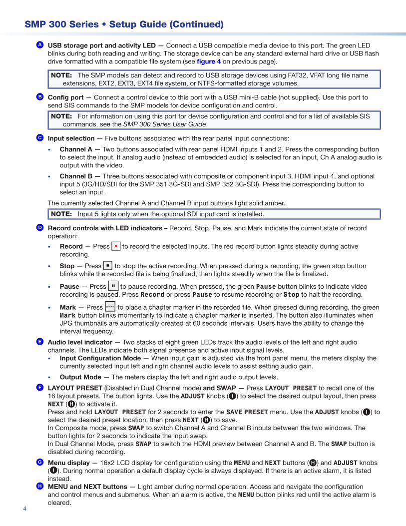
A USB storage port and activity LED — Connect a USB compatible media device to this port. The green LED blinks during both reading and writing. The storage device can be any standard external hard drive or USB flash drive formatted with a compatible file system (see figure 4 on previous page).
NOTE: The SMP models can detect and record to USB storage devices using FAT32, VFAT long file name extensions, EXT2, EXT3, EXT4 file system, or NTFS-formatted storage volumes.
B Config port — Connect a control device to this port with a USB mini-B cable (not supplied). Use this port to send SIS commands to the SMP models for device configuration and control.
NOTE: For information on using this port for device configuration and control and for a list of available SIS commands, see the SMP 300 Series User Guide.
C Input selection — Five buttons associated with the rear panel input connections:
• Channel A — Two buttons associated with rear panel HDMI inputs 1 and 2. Press the corresponding button to select the input. If analog audio (instead of embedded audio) is selected for an input, Ch A analog audio is output with the video.
• Channel B — Three buttons associated with composite or component input 3, HDMI input 4, and optional input 5 (3G/HD/SDI for the SMP 351 3G-SDI and SMP 352 3G-SDI). Press the corresponding button to select an input.
The currently selected Channel A and Channel B input buttons light solid amber.
NOTE: Input 5 lights only when the optional SDI input card is installed.
D Record controls with LED indicators – Record, Stop, Pause, and Mark indicate the current state of record operation:
• Record — Press to record the selected inputs. The red record button lights steadily during active recording.
• Stop — Press to stop the active recording. When pressed during a recording, the green stop button blinks while the recorded file is being finalized, then lights steadily when the file is finalized.
• Pause — Press to pause recording. When pressed, the green Pause button blinks to indicate video recording is paused. Press Record or press Pause to resume recording or Stop to halt the recording.
• Mark — Press MARK to place a chapter marker in the recorded file. When pressed during recording, the green Mark button blinks momentarily to indicate a chapter marker is inserted. The button also illuminates when JPG thumbnails are automatically created at 60 seconds intervals. Users have the ability to change the interval frequency.
E Audio level indicator — Two stacks of eight green LEDs track the audio levels of the left and right audio channels. The LEDs indicate both signal presence and active input signal levels. • Input Configuration Mode — When input gain is adjusted via the front panel menu, the meters display the
currently selected input left and right channel audio levels to assist setting audio gain.
• Output Mode — The meters display the left and right audio output levels.
F LAYOUT PRESET (Disabled in Dual Channel mode) and SWAP — Press LAYOUT PRESET to recall one of the 16 layout presets. The button lights. Use the ADJUST knobs (I) to select the desired output layout, then press NEXT (H) to activate it. Press and hold LAYOUT PRESET for 2 seconds to enter the SAVE PRESET menu. Use the ADJUST knobs (I) to select the desired preset location, then press NEXT (H) to save. In Composite mode, press SWAP to switch Channel A and Channel B inputs between the two windows. The button lights for 2 seconds to indicate the input swap.In Dual Channel Mode, press SWAP to switch the HDMI preview between Channel A and B. The SWAP button is disabled during recording.
G Menu display — 16x2 LCD display for configuration using the MENU and NEXT buttons (H) and ADJUST knobs (I). During normal operation a default display cycle is always displayed. If there is an active alarm, it is listed instead.
H MENU and NEXT buttons — Light amber during normal operation. Access and navigate the configuration and control menus and submenus. When an alarm is active, the MENU button blinks red until the active alarm is cleared.
5
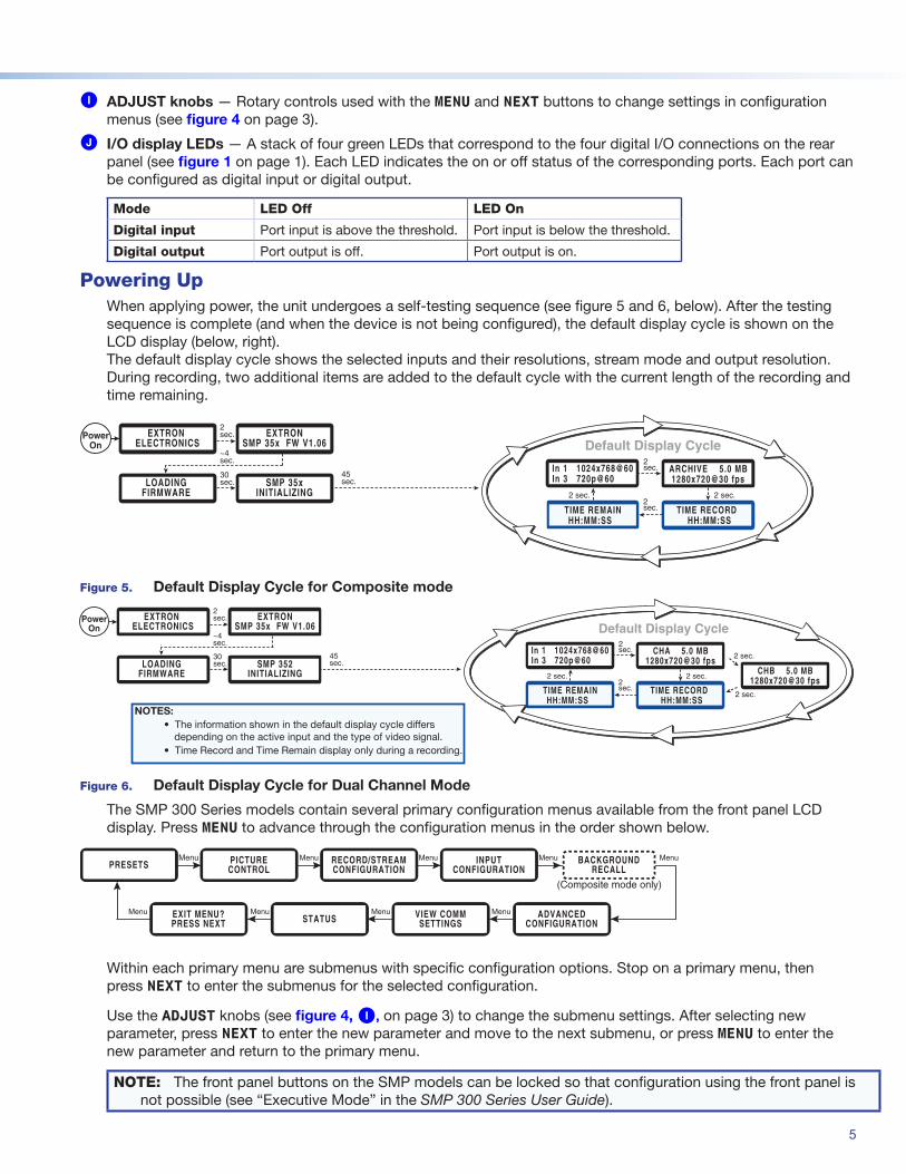
I ADJUST knobs — Rotary controls used with the MENU and NEXT buttons to change settings in configuration menus (see figure 4 on page 3).
J I/O display LEDs — A stack of four green LEDs that correspond to the four digital I/O connections on the rear panel (see figure 1 on page 1). Each LED indicates the on or off status of the corresponding ports. Each port can be configured as digital input or digital output.
Mode LED Off LED On
Digital input Port input is above the threshold. Port input is below the threshold.
Digital output Port output is off. Port output is on.
Powering UpWhen applying power, the unit undergoes a self-testing sequence (see figure 5 and 6, below). After the testing sequence is complete (and when the device is not being configured), the default display cycle is shown on the LCD display (below, right). The default display cycle shows the selected inputs and their resolutions, stream mode and output resolution. During recording, two additional items are added to the default cycle with the current length of the recording and time remaining.
Figure 5. Default Display Cycle for Composite mode
Figure 6. Default Display Cycle for Dual Channel Mode
The SMP 300 Series models contain several primary configuration menus available from the front panel LCD display. Press MENU to advance through the configuration menus in the order shown below.
(Composite mode only)
PRESETS PICTURECONTROL
RECORD/STREAMCONFIGURATION
INPUTCONFIGURATION
BACKGROUNDRECALL
Menu MenuMenu
Menu ADVANCEDCONFIGURATION
VIEW COMMSETTINGSSTATUSEXIT MENU?
PRESS NEXT
Menu MenuMenu Menu Menu
Within each primary menu are submenus with specific configuration options. Stop on a primary menu, then press NEXT to enter the submenus for the selected configuration.
Use the ADJUST knobs (see figure 4, I, on page 3) to change the submenu settings. After selecting new parameter, press NEXT to enter the new parameter and move to the next submenu, or press MENU to enter the new parameter and return to the primary menu.
NOTE: The front panel buttons on the SMP models can be locked so that configuration using the front panel is not possible (see “Executive Mode” in the SMP 300 Series User Guide).
EXTRON ELECTRONICS
2sec. EXTRON
SMP 35x FW V1.06
45sec.SMP 352
INITIALIZINGLOADING
FIRMWARE
30sec.
~4 sec.
PowerOn
NOTES: • The information shown in the default display cycle differs
depending on the active input and the type of video signal. • Time Record and Time Remain display only during a recording.
Default Display Cycle2sec.
HH:MM:SSTIME RECORD
2sec.
2 sec.
In 1 1024x768@60In 3 720p@60
2 sec.
CHA 5.0 MB1280x720@30 fps
HH:MM:SSTIME REMAIN
CHB 5.0 MB1280x720@30 fps
2 sec.
2 sec.
EXTRON ELECTRONICS
2sec. EXTRON
SMP 35x FW V1.06
45sec.SMP 35x
INITIALIZINGLOADING
FIRMWARE
30sec.
~4 sec.
PowerOn Default Display Cycle
2sec.
HH:MM:SSTIME RECORD
2sec.
2 sec.
In 1 1024x768@60In 3 720p@60
2 sec.
ARCHIVE 5.0 MB1280x720@30 fps
HH:MM:SSTIME REMAIN
6
SMP 300 Series • Setup Guide (Continued)
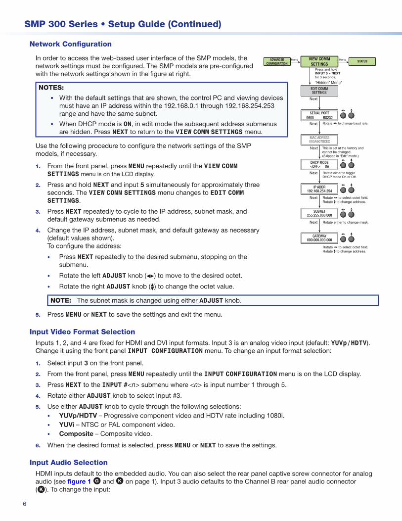
Network Configuration
In order to access the web-based user interface of the SMP models, the network settings must be configured. The SMP models are pre-configured with the network settings shown in the figure at right.
NOTES:
• With the default settings that are shown, the control PC and viewing devices must have an IP address within the 192.168.0.1 through 192.168.254.253 range and have the same subnet.
• When DHCP mode is ON, in edit mode the subsequent address submenus are hidden. Press NEXT to return to the VIEW COMM SETTINGS menu.
Use the following procedure to configure the network settings of the SMP models, if necessary.
1. From the front panel, press MENU repeatedly until the VIEW COMM SETTINGS menu is on the LCD display.
2. Press and hold NEXT and input 5 simultaneously for approximately three seconds. The VIEW COMM SETTINGS menu changes to EDIT COMM SETTINGS.
3. Press NEXT repeatedly to cycle to the IP address, subnet mask, and default gateway submenus as needed.
4. Change the IP address, subnet mask, and default gateway as necessary (default values shown). To configure the address:
• Press NEXT repeatedly to the desired submenu, stopping on the submenu.
• Rotate the left ADJUST knob ([) to move to the desired octet.
• Rotate the right ADJUST knob ({) to change the octet value.
NOTE: The subnet mask is changed using either ADJUST knob.
5. Press MENU or NEXT to save the settings and exit the menu.
Input Video Format Selection
Inputs 1, 2, and 4 are fixed for HDMI and DVI input formats. Input 3 is an analog video input (default: YUVp/HDTV). Change it using the front panel INPUT CONFIGURATION menu. To change an input format selection:
1. Select input 3 on the front panel.
2. From the front panel, press MENU repeatedly until the INPUT CONFIGURATION menu is on the LCD display.
3. Press NEXT to the INPUT #<n> submenu where <n> is input number 1 through 5.
4. Rotate either ADJUST knob to select Input #3.
5. Use either ADJUST knob to cycle through the following selections:• YUVp/HDTV – Progressive component video and HDTV rate including 1080i.• YUVi – NTSC or PAL component video.• Composite – Composite video.
6. When the desired format is selected, press MENU or NEXT to save the settings.
Input Audio Selection
HDMI inputs default to the embedded audio. You can also select the rear panel captive screw connector for analog audio (see figure 1 G and K on page 1). Input 3 audio defaults to the Channel B rear panel audio connector (K). To change the input:
Next
Next
Next
Next
Next
Next
MenuMenuADVANCEDCONFIGURATION
VIEW COMMSETTINGS
STATUS
This is set at the factory and cannot be changed.(Skipped in “Edit” mode.)
Rotate [ to change baud rate.
Rotate either to toggle DHCP mode On or Off.
Rotate [ to select octet field. Rotate { to change address.
“Hidden” Menu*
Press and hold INPUT 5 + NEXT for 3 seconds.
Rotate either to change mask.
Rotate [ to select octet field. Rotate { to change address.
SERIAL PORT9600 RS232
DHCP MODE<OFF> On
MAC ADRESS005A6078CEC
IP ADDR192.168.254.254
GATEWAY000.000.000.000
SUBNET255.255.000.000
EDIT COMMSETTINGS

7
5. Rotate either ADJUST knob to cycle through the following selections:• LPCM 2CH — Embedded digital audio (default for inputs 1, 2, and 4)• Analog — Rear panel audio (default for inputs 3 and 5)• OFF — No audio for the selected input
6. Press NEXT to save the settings.
Output Audio Selection
The recording audio output is selected from the Channel A or Channel B audio inputs or can be a mix of both.
1. From the front panel, press MENU repeatedly until the RECORD/STREAM CONFIGURATION menu is displayed.
2. Press NEXT repeatedly to cycle to the AUDIO OUTPUT submenu.
3. Rotate the left ADJUST knob ([) or right ADJUST knob ({) to cycle through the following selections:
• CH A — Selects only the Channel A audio
• CH B — Selects only the Channel B audio
• CH A + CH B — Selects a mix of both Channel A and Channel B inputs (default)
If Channel B Dual Mono Analog is enabled (from WebUI for SMP 352 or SMP 351 with LinkLicense), rotate the left ADJUST knob ([) or right ADJUST knob ({) to cycle through the following selections:
• CH A + CH B DUAL MONO — Selects both Channel A and Channel B inputs (default)
• CH B DUAL MONO — Selects only the Channel B dual mono audio
4. Press NEXT to save the settings.
The input configuration menu includes additional configuration selections to further customize output audio and video (see the SMP 300 User Guide for more information).
Encoder PresetsEncoder presets allow switching between various encoder profiles based on resolution and bitrates. There are 32 encoder presets including nine pre-defined (1 through 9 in the table below) that cover common encoder configurations for the SMP model.
Preset Number
Preset Name
Resolution Video Bitrate (Kbps)
Frame Rate (fps)
Audio Bitrate (Kbps)
Mode GOP Length
H.264 Profile
H.264 Level
1 1080p High 1920x1080 8000 30 320 VBR 30 High 4.1
2 1080p Low 1920x1080 6000 15 128 CVBR 30 Main 3.2
3* 720p High 1280x720 5000 30 192 VBR 30 High 3.1
4 720p Low 1280x720 3000 15 128 CVBR 30 Main 3.1
5 480p High 848x480 2500 30 128 VBR 30 High 3.1
6 480p Low 848x480 1500 15 80 CVBR 30 Main 3.1
7 VGA High 1280x1024 3500 30 128 VBR 30 High 4.1
8 VGA Low 1024x768 2500 15 128 VBR 30 High 3.1
9** Confidence 512x288 350 15 192 VBR 15 Base 3.0
NOTES:
• *Preset 3 is the default value for the Archive Encoder (Channel A and Channel B).
• **Preset 9 is the default value for the Confidence Encoder (Streaming = on by default).
1. On the front panel, press MENU repeatedly to cycle to the INPUT CONFIGURATION menu.
2. Press NEXT once to advance to the INPUT SELECT submenu.
3. Rotate the left or right ADJUST knob to select the desired input from the Channel A and Channel B active inputs.
4. Press NEXT repeatedly to cycle to the IN<n> AUDIO SELECT submenu, where <n> is the input selected in step 3.

8
SMP 300 Series • Setup Guide (Continued)
Encoder presets are saved and recalled from the Presets menu on the front panel.
To recall an encoder preset:
1. On the front panel, press MENU until the PRESETS menu displays.
2. If COMPOSITE mode is selected, press NEXT to cycle to the ARCHIVE ENCODER RECALL submenu.
If DUAL mode is selected, press NEXT to cycle to the CH A ARCH ENCODER RECALL submenu. Use the horizontal ADJUST knob ([) to select between CH A ARCH, CH B ARCH, and CONFIDENCE. Use the vertical ADJUSTknob ({) to recall a predefined or previously saved preset number.
3. Rotate the left or right ADJUST knob to select a predefined or previously saved preset number (see the table on previous page).
4. Press NEXT to select the preset.
Layout Presets (For Composite Mode only)The five inputs are divided into Channel A (inputs 1 and 2) and Channel B (inputs 3, 4, and 5). There are 16 layout presets including 12 that are pre-defined to save input selections and their appearance on the recording or the output. Layout presets are saved and recalled from the front panel menu (see figure 4, F on page 3) or the embedded web pages (see the SMP 300 Help File or the SMP 300 User Guide for embedded web page assistance).
NOTE: In dual channel mode, the confidence encoder always displays ChA and ChB side-by-side.
To select a layout:
1. Press LAYOUT PRESET to select the layout preset menu.
2. Rotate either ADJUST knob ([) to cycle through the layout selections.
3. When the desired layout is visible, press NEXT to make it the active layout.
To Record a FileBoth SMP models create MP4 media files by blending Channel A and Channel B inputs into a single video image. Additionally, the SMP 352 is able to generate an Archive quality MP4 for each of the input channels, import an iCalendar schedule via the web-based user interface, or start a recording from the front panel or webUI (ad hoc). Recordings are stored to internal storage, to recording media connected to the front or rear USB ports, or both. The recording location defaults to the internal storage.
To configure an ad hoc recording:
1. From the front panel, press MENU repeatedly until the RECORD/STREAM CONFIGURATION menu is displayed.
2. Press NEXT once and select ARCHIVE from the ENCODER submenu using either ADJUST knobs.
3. Press NEXT once and select either COMPOSITE or DUAL mode from the ENCODER MODE submenu using either ADJUST knob.
a. If COMPOSITE mode is selected, press NEXT repeatedly to cycle to the RECORDING submenu and use either ADJUST knob to select OFF, SINGLE, or DUAL INTERNAL + 2nd recording mode. If INTERNAL + 2nd recording mode is selected, the recording file will be saved to internal and external storage.
b. If DUAL mode is selected:• Press NEXT once and select CHA or CHB from the ENCODER submenu using either ADJUST knob
• Press NEXT once and select SINGLE or OFF from the RECORDING submenu using either ADJUST knob
4. Press NEXT to cycle to the REC TO submenu.
5. Rotate the left ADJUST knob ([) to select from the following:• INTERNAL — Record to internal storage <default>.
• USBFRONT <VOLNAME> — Record to the device connected to the front panel USB port.
• USBREAR <VOLNAME> — Record to the device connected to the rear panel USB port.
• AUTO — When the record destination is “Auto,” if USB devices are present, the front USB port has priority, then the rear USB port, then internal storage.
NOTE: If a recording device has more than one logical volume, rotate the vertical ADJUST knob ({) to cycle through the volumes. In auto mode, the volume with the most space for that port is used to store content.
9
6. Select the audio output (see Audio Output Selection on page 7).
7. If composite mode is selected, press the front panel LAYOUT PRESET button and select a layout (see Layout Presets on previous page).
8. Press the desired front panel input buttons.
9. Press the front panel Record button.
10. Monitor the record time and and remaining time on the LCD default display cycle.
11. Press Pause to temporarily suspend recording. Press Pause again to resume the recording and place a chapter marker on the file. Press Stop to cease recording and place an end of file marker on the recording.
StreamingBoth SMP models support multiple simultaneous stream encoders. Additionally, the SMP 352 supports Channel A and Channel B archive streaming. Each can have a different resolution, frame rate, and bitrate and independent streaming protocol methods. The output defaults to both record and stream the selected input.
• Archive (Channel A and Channel B in Dual Channel mode) — Highest quality for both recording and streaming (default: Pull, unicast RTP/UDP).
• Confidence — For streaming only (default: Pull, unicast RTP/UDP).
NOTES:
• To view a confidence stream on the web-based UI, leave the confidence encode setting at default values.
• Preview will not be shown if version Chrome 42 or later is used.
To upload a recording to a server share folder:
Files recorded to internal memory can also be uploaded automatically (after the recording completes) to a server shared folder via FTP, SFTP or CIFS (see the SMP 300 Series Help file for instructions and additional file publishing options).
To decode the archive and confidence streams:
To view the confidence stream, go to the embedded webpage AV Controls Panel. The SMP models use the Extron SMP plugin to view the streams. Archive and confidence streams can also be decoded using an Extron SMD 101 or SMD 202 decoder or compatible third party players such as VLC® and QuickTime®. To change the default viewer, see the SMP 300 Series User Guide.
Access Internal Content
The SMP 300 Series device has internal memory reserved for local content. Internal content is viewed from the web-based user interface Files Management tab (see the SMP 300 Series User Guide or the SMP 300 Series Help file for complete instructions).
Recording folders and files can be transferred directly from the SMP 300 Series device to a computer on the same network using an SFTP client such as Filezilla®, a free FTP program. Connect to the SMP 300 Series device at sftp://<SMP 351 IP>:22022. Log in using “admin” or “user” credentials (see the SMP 300 Series User Guide for more information).
About the Web-based User Interface
The web-based user interface can view, configure, and control the SMP 300 Series device with a PC from the LAN port using a standard web browser (see Network Configuration on page 6). This section details how to access the web-based user interface. For more information on using the web-based user interface (see the SMP 300 Series User Guide available on the www.extron.com or click the ? button on the user interface page (see figure 7 on next page) to open the SMP 300 Series Help File).

10
SMP 300 Series • Setup Guide (Continued)
68-2238-50 Rev. B09 16
Extron Headquarters+1.800.633.9876 (Inside USA/Canada Only)
Extron USA - West Extron USA - East +1.714.491.1500 +1.919.850.1000 +1.714.491.1517 FAX +1.919.850.1001 FAX
Extron Europe+800.3987.6673 (Inside Europe Only)
+31.33.453.4040 +31.33.453.4050 FAX
Extron Asia+65.6383.4400+65.6383.4664 FAX
Extron Japan+81.3.3511.7655+81.3.3511.7656 FAX
Extron China+86.21.3760.1568 +86.21.3760.1566 FAX
Extron Middle East+971.4.299.1800+971.4.299.1880 FAX
Extron Australia+61.8.8351.2188+61.8.8351.2511 FAX
Extron India1800.3070.3777 (Inside India Only)
+91.80.3055.3777 +91.80.3055.3737 FAX
© 2016 Extron Electronics All rights reserved. www.extron.com
Accessing the Web-based User Interface
NOTE: The SMP models can be accessed in Windows using Microsoft® Internet Explorer® version 10 or higher (recommended), Explorer Mozilla® Firefox® (version 35 or higher), or Google® Chrome™ (version 37 or higher), and on a Mac® OS® platform (Mac OS X or higher) using Safari® (version 8 or higher) (see the SMP 300 Series User Guide for current compatibility).
Open a web browser on the control computer and enter the IP address of the SMP models into the address bar (for example, http://192.168.254.254). Press <Enter>. The default user interface page opens.
Figure 7. Default User Interface Page
The AV Controls panel on the left remains open unless closed by the user. It provides the most common input switching and start and stop recording access. Stream information and output and selected input information are in the middle panel and current or scheduled events are in the right panel. Click the help file button ( ? ) in the top right corner of the default page and on the various pages and tabs within the web-based user interface to open the SMP 300 Series Help File for more information.