SMP / SMP-COM / SMP-MAX series D1C004XEe.pdf · 2012-05-26 · 3-4 SMP-MAX INTRODUCTION SMP-MAX...
27
SMP / SMP-COM / SMP-MAX series R222 3
Transcript of SMP / SMP-COM / SMP-MAX series D1C004XEe.pdf · 2012-05-26 · 3-4 SMP-MAX INTRODUCTION SMP-MAX...

SMP / SMP-COM / SMP-MAX seriesR222
3


www.radiall.com
3-3
CONTENTS
SMPIntroduction . . . . . . . . . . . . . . . . . . . . . . . . . . . . . . . . . . . . . . . . . . . . . . . . . . . . . . . . . . . . . . . . . . . . . . . . . . . . . . . . . . . . . . . . . . . . . . . . . . . . . . . . . . . . . . . . . . . . . . . . . . . . . . . . . . . . . . . . . . . . . . . . . . . . . . . . . . . . 3-5
Interface . . . . . . . . . . . . . . . . . . . . . . . . . . . . . . . . . . . . . . . . . . . . . . . . . . . . . . . . . . . . . . . . . . . . . . . . . . . . . . . . . . . . . . . . . . . . . . . . . . . . . . . . . . . . . . . . . . . . . . . . . . . . . . . . . . . . . . . . . . . . . . . . . . . . . . . . 3-6 to 3-7
Characteristics . . . . . . . . . . . . . . . . . . . . . . . . . . . . . . . . . . . . . . . . . . . . . . . . . . . . . . . . . . . . . . . . . . . . . . . . . . . . . . . . . . . . . . . . . . . . . . . . . . . . . . . . . . . . . . . . . . . . . . . . . . . . . . . . . . . . . . . . . . . . . . . . . . . . . . . . 3-8
Plugs and jacks . . . . . . . . . . . . . . . . . . . . . . . . . . . . . . . . . . . . . . . . . . . . . . . . . . . . . . . . . . . . . . . . . . . . . . . . . . . . . . . . . . . . . . . . . . . . . . . . . . . . . . . . . . . . . . . . . . . . . . . . . . . . . . . . . . . . . . . . . . . . . . . . . . . . . . 3-10
Receptacles . . . . . . . . . . . . . . . . . . . . . . . . . . . . . . . . . . . . . . . . . . . . . . . . . . . . . . . . . . . . . . . . . . . . . . . . . . . . . . . . . . . . . . . . . . . . . . . . . . . . . . . . . . . . . . . . . . . . . . . . . . . . . . . . . . . . . . . . . . . . . . . . . 3-11 to 3-13
Panel shroud . . . . . . . . . . . . . . . . . . . . . . . . . . . . . . . . . . . . . . . . . . . . . . . . . . . . . . . . . . . . . . . . . . . . . . . . . . . . . . . . . . . . . . . . . . . . . . . . . . . . . . . . . . . . . . . . . . . . . . . . . . . . . . . . . . . . . . . . . . . . . . . . 3-13 to 3-14
Glass bead . . . . . . . . . . . . . . . . . . . . . . . . . . . . . . . . . . . . . . . . . . . . . . . . . . . . . . . . . . . . . . . . . . . . . . . . . . . . . . . . . . . . . . . . . . . . . . . . . . . . . . . . . . . . . . . . . . . . . . . . . . . . . . . . . . . . . . . . . . . . . . . . . . . . . . . . . . . . . 3-14
Adapters . . . . . . . . . . . . . . . . . . . . . . . . . . . . . . . . . . . . . . . . . . . . . . . . . . . . . . . . . . . . . . . . . . . . . . . . . . . . . . . . . . . . . . . . . . . . . . . . . . . . . . . . . . . . . . . . . . . . . . . . . . . . . . . . . . . . . . . . . . . . . . . . . . . . . . 3-14 to 3-15
Packaging . . . . . . . . . . . . . . . . . . . . . . . . . . . . . . . . . . . . . . . . . . . . . . . . . . . . . . . . . . . . . . . . . . . . . . . . . . . . . . . . . . . . . . . . . . . . . . . . . . . . . . . . . . . . . . . . . . . . . . . . . . . . . . . . . . . . . . . . . . . . . . . . . . . . . . . . . . . . . . 3-15
Assembly instructions . . . . . . . . . . . . . . . . . . . . . . . . . . . . . . . . . . . . . . . . . . . . . . . . . . . . . . . . . . . . . . . . . . . . . . . . . . . . . . . . . . . . . . . . . . . . . . . . . . . . . . . . . . . . . . . . . . . . . . . . . . . . . . . . . . . . . . . . . . . . . . 3-16
Panel drilling . . . . . . . . . . . . . . . . . . . . . . . . . . . . . . . . . . . . . . . . . . . . . . . . . . . . . . . . . . . . . . . . . . . . . . . . . . . . . . . . . . . . . . . . . . . . . . . . . . . . . . . . . . . . . . . . . . . . . . . . . . . . . . . . . . . . . . . . . . . . . . . . . . . . . . . . . . 3-20
SMP-COMIntroduction . . . . . . . . . . . . . . . . . . . . . . . . . . . . . . . . . . . . . . . . . . . . . . . . . . . . . . . . . . . . . . . . . . . . . . . . . . . . . . . . . . . . . . . . . . . . . . . . . . . . . . . . . . . . . . . . . . . . . . . . . . . . . . . . . . . . . . . . . . . . . . . . . . . . . . . . . . . . 3-5
Interface . . . . . . . . . . . . . . . . . . . . . . . . . . . . . . . . . . . . . . . . . . . . . . . . . . . . . . . . . . . . . . . . . . . . . . . . . . . . . . . . . . . . . . . . . . . . . . . . . . . . . . . . . . . . . . . . . . . . . . . . . . . . . . . . . . . . . . . . . . . . . . . . . . . . . . . . . . . . . . . . . 3-7
Characteristics . . . . . . . . . . . . . . . . . . . . . . . . . . . . . . . . . . . . . . . . . . . . . . . . . . . . . . . . . . . . . . . . . . . . . . . . . . . . . . . . . . . . . . . . . . . . . . . . . . . . . . . . . . . . . . . . . . . . . . . . . . . . . . . . . . . . . . . . . . . . . . . . . . . . . . . . 3-9
Plugs and jacks . . . . . . . . . . . . . . . . . . . . . . . . . . . . . . . . . . . . . . . . . . . . . . . . . . . . . . . . . . . . . . . . . . . . . . . . . . . . . . . . . . . . . . . . . . . . . . . . . . . . . . . . . . . . . . . . . . . . . . . . . . . . . . . . . . . . . . . . . . . . 3-17 to 3-18
Receptacles . . . . . . . . . . . . . . . . . . . . . . . . . . . . . . . . . . . . . . . . . . . . . . . . . . . . . . . . . . . . . . . . . . . . . . . . . . . . . . . . . . . . . . . . . . . . . . . . . . . . . . . . . . . . . . . . . . . . . . . . . . . . . . . . . . . . . . . . . . . . . . . . . . . . . . . . . . . 3-18
Adapters . . . . . . . . . . . . . . . . . . . . . . . . . . . . . . . . . . . . . . . . . . . . . . . . . . . . . . . . . . . . . . . . . . . . . . . . . . . . . . . . . . . . . . . . . . . . . . . . . . . . . . . . . . . . . . . . . . . . . . . . . . . . . . . . . . . . . . . . . . . . . . . . . . . . . . . . . . . . . . . . 3-19
Measurement . . . . . . . . . . . . . . . . . . . . . . . . . . . . . . . . . . . . . . . . . . . . . . . . . . . . . . . . . . . . . . . . . . . . . . . . . . . . . . . . . . . . . . . . . . . . . . . . . . . . . . . . . . . . . . . . . . . . . . . . . . . . . . . . . . . . . . . . . . . . . . . . . . . . . . . . . . 3-19
Packaging . . . . . . . . . . . . . . . . . . . . . . . . . . . . . . . . . . . . . . . . . . . . . . . . . . . . . . . . . . . . . . . . . . . . . . . . . . . . . . . . . . . . . . . . . . . . . . . . . . . . . . . . . . . . . . . . . . . . . . . . . . . . . . . . . . . . . . . . . . . . . . . . . . . . . . . . . . . . . . 3-19
Panel drilling . . . . . . . . . . . . . . . . . . . . . . . . . . . . . . . . . . . . . . . . . . . . . . . . . . . . . . . . . . . . . . . . . . . . . . . . . . . . . . . . . . . . . . . . . . . . . . . . . . . . . . . . . . . . . . . . . . . . . . . . . . . . . . . . . . . . . . . . . . . . . . . . . . . . . . . . . . 3-20
Assembly instructions . . . . . . . . . . . . . . . . . . . . . . . . . . . . . . . . . . . . . . . . . . . . . . . . . . . . . . . . . . . . . . . . . . . . . . . . . . . . . . . . . . . . . . . . . . . . . . . . . . . . . . . . . . . . . . . . . . . . . . . . . . . . . . . . . . . . . . . . . . . . . . 3-20
SMP-MAXIntroduction . . . . . . . . . . . . . . . . . . . . . . . . . . . . . . . . . . . . . . . . . . . . . . . . . . . . . . . . . . . . . . . . . . . . . . . . . . . . . . . . . . . . . . . . . . . . . . . . . . . . . . . . . . . . . . . . . . . . . . . . . . . . . . . . . . . . . . . . . . . . . . . . 3-4 and 3-21
Characteristics . . . . . . . . . . . . . . . . . . . . . . . . . . . . . . . . . . . . . . . . . . . . . . . . . . . . . . . . . . . . . . . . . . . . . . . . . . . . . . . . . . . . . . . . . . . . . . . . . . . . . . . . . . . . . . . . . . . . . . . . . . . . . . . . . . . . . . . . . . . . . . . . . . . . . . . 3-22
Jacks . . . . . . . . . . . . . . . . . . . . . . . . . . . . . . . . . . . . . . . . . . . . . . . . . . . . . . . . . . . . . . . . . . . . . . . . . . . . . . . . . . . . . . . . . . . . . . . . . . . . . . . . . . . . . . . . . . . . . . . . . . . . . . . . . . . . . . . . . . . . . . . . . . . . . . . . . . . . . . . . . . . . 3-23
Plugs . . . . . . . . . . . . . . . . . . . . . . . . . . . . . . . . . . . . . . . . . . . . . . . . . . . . . . . . . . . . . . . . . . . . . . . . . . . . . . . . . . . . . . . . . . . . . . . . . . . . . . . . . . . . . . . . . . . . . . . . . . . . . . . . . . . . . . . . . . . . . . . . . . . . . . . . . . . . . . . . . . . . 3-23
Receptacles . . . . . . . . . . . . . . . . . . . . . . . . . . . . . . . . . . . . . . . . . . . . . . . . . . . . . . . . . . . . . . . . . . . . . . . . . . . . . . . . . . . . . . . . . . . . . . . . . . . . . . . . . . . . . . . . . . . . . . . . . . . . . . . . . . . . . . . . . . . . . . . . . . . . . . . . . . . . 3-24
Adapters . . . . . . . . . . . . . . . . . . . . . . . . . . . . . . . . . . . . . . . . . . . . . . . . . . . . . . . . . . . . . . . . . . . . . . . . . . . . . . . . . . . . . . . . . . . . . . . . . . . . . . . . . . . . . . . . . . . . . . . . . . . . . . . . . . . . . . . . . . . . . . . . . . . . . . . . . . . . . . . . 3-25
Panel drilling . . . . . . . . . . . . . . . . . . . . . . . . . . . . . . . . . . . . . . . . . . . . . . . . . . . . . . . . . . . . . . . . . . . . . . . . . . . . . . . . . . . . . . . . . . . . . . . . . . . . . . . . . . . . . . . . . . . . . . . . . . . . . . . . . . . . . . . . . . . . . . . . . . . . . . . . . . 3-26
Pages
SMP/
SMP-
COM
/SM
P-M
AX

www.radiall.com
3-4
SMP-
MAX INTRODUCTION
SMP-MAX Receptacle
IMP
SMP-MAX Adapter
The Best Systems
Radiall’s engineers work with your engineers allowing us to develop the best competitively
priced misalignment RF coaxial interconnect solutions on the market today.
The Best Choices
Radiall offers more board 2 board choices with four different product groups and ten
connector series that can address the most demanding wireless telecom applications
required for the new generation of infrastructure compact equipment. From base stations
to repeaters and even handheld and GPS devices, we have a tailored connector solution
for you; including the new SMP-MAX, SMP-Spring, IMP-Spring and other large, limited and
no misalignment solutions.
SMP-MAX
Get the best for less with the new SMP-MAX large misalignment solution. Its patented impedance matching insulator is optimized for a larger operating gap between connectors making it easier for engineers to handle a board 2 board distance tolerance of at least .078” (2.0 mm) without a spring, which is 300% more than the standard SMP! It features a 3° minimum tilt (radiall travel) and it has an operating frequency range of DC-6 GHz and a 1.2 max VSWR guaranteed at DC-3 GHz.
Spring-loaded Connectors
Radiall’s one connector IMP-Spring and three connector SMP-Spring and MMBX-Spring large misalignment spring-loaded series are the best for increased maximum distance tolerances.IMP-Spring is a cost effective unique one connector solution that offers up to .023" (.6 mm) board 2 board distance tolerance with a tilt (radial travel) up to 4.5°. The new SMP-Spring and MMBX-Spring offer up to .078” (2 mm) board 2 board distance tolerance and a 4.5° tilt (radial travel).All spring-loaded solutions feature consistent VSWR and low RF leakage.
Limited Misalignment
Radiall’s one connector IMP and three connector SMP and MMBX limited misalignment series are designed for applications requiring relatively precise distance tolerance of up to .023" (.6 mm) with a tilt (radial travel) of up to 4.5°.
No Misalignment
Radiall’s MMT, MMS and MCX series are designed for applications requiring little or no distance tolerance between boards.
IMP-Spring and SMP-Spring
BOARD TO BOARD SOLUTIONS

www.radiall.com
3-5
SMP/
SMP-
COMINTRODUCTION
The SMP series offers 3 levels of retention provided by the connectors with male center contact:- full detent for a positive locking with a maximum
retention- limited detent for a positive locking with a medium
retention- smooth bore for the lowest retention.
The SMP series meets MIL STD 348 specifications the DESC specifications 94007 & 94008.
Their small size permits connector center-to-center spacing as low as 4.8 mm.
Radiall also offers multi-way connectors with SMP interface to optimize the positioning of connectors, increasing density and misalignment tolerances through the design of a metal bar. The metal bar, in which connectors are already inserted, permits the design engineer to connect several SMP connectors while at the same time maintain reasonable retention.
SMP-COM is fully intermateable with the standard SMP and has been optimized up to 12.4 GHz meeting the telecommunication applications needs.
Typical combinations of SMP connectors:
Cable to module
Thread-in shroud for limited space
Module to module (2 hole flange shroud)
GENERAL• Microminiature• Blindmate• Excellent vibration and shock performances• Allows axial and radial misalignments
APPLICATIONS• High density packaging• Phased array antenna• Satellite• Airborne/Shipborne/Ground radar• Communication equipment• Board to board applications
SMP SMP-COM
50Ω DC - 40 GHz DC - 12.4 GHz

www.radiall.com
3-6
SMP INTERFACE SMP
JACK WITH MALE CENTER CONTACT (Full Detent or Limited Detent)
JACK WITH MALE CENTER CONTACT (Smooth Bore)
PLUG WITH FEMALE CENTER CONTACT AND EMI SHIELD (Cabled connection)
PLUG WITH FEMALE CENTER CONTACT (Cabled connection)
Letter mm inch Notemin. max. min. max. A 3.15 3.20 .124 .126 DiaB 2.74 2.84 .108 .112C 0.52 0.60 .0205 .0235E 0.00 0 Center contact recessionF 1.14 1.40 .045 .055G 0.36 0.41 .014 .016 Dia
H2.90 3.00 .114 .118 Dia: Full Detent3.00 3.10 .118 .122 Dia: Limited Detent
J 3.53 3.68 .139 .145 DiaK 0.84 0.94 .033 .037
L1.30 1.45 .051 .057 Full Detent1.37 1.52 .054 .060 Limited Detent
M 0.08 0.20 .003 .008 30 Degree (nom.) 40 50 40 50 Degree
Letter mm inch Notemin. max. min. max. A 3.43 .135 DiaB 2.84 .112C 0.46 0.64 .018 .025D 0.00 0 Dielectric projectionE 0.00 0.20 0 .008 Center contact recessionF 1.78 0.70
Letter mm inch Notemin. max. min. max. A 3.43 .135 DiaB 2.84 .112C 0.46 0.64 .018 .025D 0.00 0 Dielectric projectionE 0.00 0.20 0 .008 Center contact recessionF 1.78 0.70
Letter mm inch Notemin. max. min. max. A 3.12 3.23 .123 .127 DiaB 2.74 2.84 .108 .112E 0.00 0 Center contact recessionF 1.14 1.40 .045 .055G 0.36 0.41 .014 .016J 3.53 3.68 .139 .145 DiaK 0.84 0.94 .033 .037L 1.50 1.65 .059 .065M 0.08 0.20 .003 .008 40 50 40 50 Degree

www.radiall.com
3-7
SMP/
SMP-
COMINTERFACE SMP
INTERFACE SMP-COM
JACK WITH MALE CENTER CONTACT (Catcher’s Mitt)
MALE CONNECTOR (Full detent or Limited detent)
MALE CONNECTOR (Smooth bore)
FEMALE CONNECTOR
Letter mm inch Notemin. max. min. max. A 3.12 3.23 .123 .127 DiaC 5.40 5.50 .213 .217 DiaD 0.37 0.39 .0146 .0154 DiaF 1.10 1.18 .043 .046G 2.77 2.81 .109 .111K 0.00 0 Center contact recessL 0.00 0 Insulator recessM 1.15 1.39 .045 .055
Note: Catcher’s Mitt interface is not defined in MIL-STD-348 standard.
Dia A 3.18+/-0.02Dia B (Full detent) 2.95+/-0.02
Dia B (Limited detent) 3.05+/-0.02Dia C 3.59 +/-0.02Dia D 0.38+/-0.02
E 0.56+/-0.03F 0.2+/-0.025
G (Full detent) 2.79+/-0.02G (Limited detent) 2.77+/-0.02
H 0.86+/-0.02J 0.15+/-0.05K 0.07+/-0.07L 1.27+/-0.12X 30°+/-0.5°Y 30°+/-0.5°Z 45° nom
Dia A 3.18+/-0.02Dia B 3.59+/-0.02Dia C 0.38+/-0.02
D 0.86+/-0.02E 0.2+/-0.025F 2.79+/-0.02G 0.15+/-0.05H 0.07+/-0.07J 1.27+/-0.12X 30°+/-0.5°Y 45° nom
Dia A 3.275+/-0.025Dia B 0.49+/-0.02
C 0.05+/-0.05D 0.05+/-0.05E 0.59+/-0.02F 0.76+/-0.1G 3.4+/-0.03

www.radiall.com
3-8
SMP
ELECTRICAL CHARACTERISTICS Impedance 50ΩFrequency range DC - 40 GHzTypical V.S.W.R.
• Straight styles• Right angle styles• Adapters• Receptacles
DC-12 GHz1.151.251.101.30
12-26.5 GHz1.151.351.15-
26.5-40 GHz1.5-
1.5-
Insertion loss (dB) 0.12 √F (F in GHz)Insulation resistance (MΩ) 5000Voltage rating (V.R.M.S.) 335Dielectric withstanting voltage (V.R.M.S.) 500RF leakage -80 dB to 3 GHz
-65 dB from 3 to 26.5 GHz
MECHANICAL CHARACTERISTICSsmooth bore limited detent full detent
Mechanical endurance (matings) 1000 500 100Engagement and separation force (N) 9 max. - 2.2 min. 45 max. - 9 min. 68 max. - 22 min.Radial misalignmentAxial misalignment
± 0.25 mm (± .010") 0, + 0.25 mm (0/ .010")
Vibration MIL-STD-202 method 204, test condition DShock MIL-STD-202 method 213, test condition IThermal shock MIL-STD-202 method 107, test condition BCable retention (N) .047"
.085"45200
Contact captivation axial (N) 6.8
ENVIRONMENTAL CHARACTERISTICS Operating temperature -65°C / +165°C
MATERIALS Cable connector with female center contact Beryllium copperCable connector with male center contact
BodiesSoldering part
Stainless steelBrass
Receptacles, shrouds Stainless steelIn series adapters Beryllium copperCenter contacts Beryllium copperCenter contacts for glass seal Iron nickel cobalt sealing alloyInsulators PTFE
PLATING Cable connector with female center contact GoldCable connector with male center contact
BodiesSoldering part
PassivatedGold
Receptacles, shrouds PassivatedIn series adapters GoldCenter contacts GoldCenter contacts for glass seal Gold
Test/characteristics Values/remarks
CHARACTERISTICS
The SMP small size dramatically increases the packaging density of 40 GHz connections(see picture: SMA 2.9/SMP).
Standard packaging = 100 pieces.
All dimensions are given in mm

www.radiall.com
3-9
SMP-
COM
ELECTRICAL CHARACTERISTICS Impedance 50ΩFrequency range DC - 6 GHz (optimized)
DC - 12.4 GHz (working range)
Typical V.S.W.R.• Straight styles• Right angle styles• Receptacles
DC - 2.5 GHz1.101.151.06
2.5 - 6 GHz1.151.251.10
Insertion loss (dB) 0.12 √F (F in GHz)Insulation resistance (MΩ) 5000Voltage rating (V.R.M.S.) 750RF leakage -55 dB 0 to 3 GHz
-40 dB from 3 to 6 GHz
MECHANICAL CHARACTERISTICSsmooth bore limited detent full detent
Mechanical endurance (matings) 100Engagement and separation force (N) 9 max. - 2.2 min. 45 max. - 9 min. 68 max. - 22 min.Radial misalignmentAxial misalignment
± 0.25 mm0, +0.25 mm
Moisture resistance MIL-STD-202 method 106Cable retention (N) • .085“ semi-rigid
• 2/50/S • 2.6/50/S
2003558
Contact captivation axial (N) 6.8
ENVIRONMENTAL CHARACTERISTICS Operating temperature • Standard
• Semi-rigid-55°C / +125°C-55°C / +105°C
MATERIALS Cable connectors Beryllium copper or brassReceptacles BrassIn series adapters Beryllium copperCenter contacts Beryllium copper/brassInsulators PTFE/PEEK
PLATING Cable connectors NPGRReceptacles NPGRIn series adapters NPGRCenter contacts NPGR
Test/characteristics Values/remarks
CHARACTERISTICS
Standard packaging = 100 pieces.
All dimensions are given in mm

3-10
PLUGS AND JACKS
PLUG, SOLDER TyPE FOR SEMI-RIGID CABLES (with female center contact)
Cable group Cable group dia. Part number Fig Dimensions mm (inch) Captive centercontact Orientation Finish
/ a / b.047” semi-rigid .047” R222 051 000
11.30 (.050) 0.30 (.012)
no straightGold
RG405 .085" R222 052 000 2.30 (.091) 0.53 (.021).047” semi-rigid .047” R222 151 000
21.30 (.050)
yes right angleRG405 .085" R222 152 000 2.30 (.091)
SMP
Fig. 1 Fig. 2
Cable group Cable group dia. Part number Retention Dimensions mm (inch) Captive centercontact
Panel drilling Finish
/ a / b
RG405 .085"
R222 302 002 Full detent
2.30 (.091) 0.55 (.022) no P05
passivated+ gold
(soldering part)
R222 302 302 Limited detent
R222 302 702 Smooth bore
Cable group Cable group dia. Part number Retention Dimensions mm (inch) Captive centercontact
Panel drilling Finish
/ a / b
RG405 .085"
R222 252 001 Full detent
2.30 (.091) 0.60 (.024) no P01
passivated+ gold
(soldering part)
R222 252 301 Limited detent
R222 252 702 Smooth bore
BULKHEAD FEEDTHROUGH JACK, SOLDER TyPE FOR SEMI RIGID CABLES (with male center contact)
TWO HOLE FLANGE JACK SOLDER TyPE FOR SEMI RIGID CABLES (with male center contact)
To download data sheets and assembly instructions, visit www.radiall.com & enter the part number in the Search box.Bold part numbers represent products typically in stock & available for immediate shipment.
See page 8 and 9 for packaging information.

3-11
PCB STRAIGHT RECEPTACLE, 4 SOLDER LEGS (with male center contact)
PCB STRAIGHT RECEPTACLE, SURFACE MOUNT (with male center contact)
PCB RECEPTACLE, EDGE CARD MOUNT (with male center contact)
Part number Fig Retention Assembly instructions Finish PackagingR222 408 350
1limited detent
M04Gold
Tape & reel - 500 piecesR222 408 750 smooth bore Tray 100 piecesR222 409 030 2 full detent M05 100 piecesR222 508 000
3
full detent
M03 Passivated + gold (soldering area)
Tape & reel500 pieces
R222 508 300 limited detentR222 508 700 smooth boreR222 508 722 catcher's mitt
Part number Retention Assembly instructions Finish PackagingR222 423 023 full detent
M01 Gold Tape & reel - 100 piecesR222 423 320 limited detentR222 423 720 smooth bore
Part number Retention Dimensions mm (inch) PCB mounting Finisha
R222 426 000 full detent2.5 (.098) P03 GoldR222 426 300 limited detent
R222 426 700 smooth bore
Fig. 1 Fig. 2 Fig. 3
SMPSTRAIGHT RECEPTACLES
To download data sheets and assembly instructions, visit www.radiall.com & enter the part number in the Search box.Bold part numbers represent products typically in stock & available for immediate shipment.See page 8 and 9 for packaging information.

3-12
RECEPTACLES
PCB STRAIGHT RECEPTACLE, PIN & PASTE MOUNT (with male center contact)
PCB RIGHT ANGLE RECEPTACLE, 4 SOLDER LEGS (with male center contact)
SQUARE FLANGE EXTENDED DIELECTRIC RECEPTACLE
THREAD-IN RECEPTACLE (with male center contact)
Part number Retention Assembly instructions FinishR222 428 000 Full detent
M02passivated
+ gold (soldering part)R222 428 300 Limited detentR222 428 700 Smooth bore
Part number Retention PCB mounting FinishR222 680 000 Full detent
P04passivated
+ gold (soldering part)R222 680 300 Limited detentR222 680 700 Smooth bore
Part number Retention Captive center contact Panel drilling FinishR222 414 701 Smooth bore yes P07 passivated
SMP
Part number Retention Dimensions mm (inch) FinishA B C DR222 561 001 Full detent
4.8(.191)
7.1(.278)
0.46(.018)
1.45(.057) passivated
R222 561 301 Limited detentR222 561 701 Smooth bore
R222 561 331 Limited detent 6.2(.243)
8.3 (.326) adjustablepin +/-0.5
1.0(.04)
0.3(.012)
To download data sheets and assembly instructions, visit www.radiall.com & enter the part number in the Search box.Bold part numbers represent products typically in stock & available for immediate shipment.
See page 8 and 9 for packaging information.

3-13
PANEL STRAIGHT HERMETIC RECEPTACLE, SOLDER MOUNT (with male center contact)
PANEL SHROUD, PRESS-IN MOUNT (no center contact)
Part number Retention Fig Finish NoteR222 645 020 Full detent 1
goldShort body 1 mm glass seal
R222 645 300 Limited detent2 1.5 mm glass seal
R222 645 700 Smooth bore
Part number Retention Panel drilling FinishR222 402 021 Full detent
P06 passivatedR222 402 321 Limited detentR222 402 721 Smooth bore
SMPRECEPTACLES AND PANEL SHROUD
Fig. 1 Fig. 2
This shroud is designed to be used with hermetic glass seal R280 752 000 (see page 3-14)
PANEL SHROUD, 2 HOLES FLANGE MOUNT (no center contact)
Part number Retention Panel drilling FinishR222 450 001 Full detent P02 passivated
This shroud is designed to be used with hermetic glass seal R280 752 000 (see page 3-14)
To download data sheets and assembly instructions, visit www.radiall.com & enter the part number in the Search box.Bold part numbers represent products typically in stock & available for immediate shipment.See page 8 and 9 for packaging information.

3-14
PANEL SHROUD, GLASS BEAD AND ADAPTERSSM
PPANEL SHROUD, THREAD-IN MOUNT (no center contact)
HERMETIC GLASS BEAD
Part number Retention FinishR222 550 001 Full detent
passivatedR222 550 301 Limited detentR222 550 701 Smooth bore
This shroud is designed to be used with hermetic glass seal R280 752 000 (see page 3-14)
Part number
R280 752 000
This hermetic glass bead is designed to be used with the above shrouds.
Part number Fig Dimensions A mm (inch) Type FinishR222 705 000
1
6.45 (.254)
Fixed length
gold
R222 705 200 5.7 (.224)R222 705 220 10.3 (.405)R222 705 230 10.0 (.395)R222 705 400 2 6.45 (.254) Fixed length with sealing gasket
R222 723 100
3
min 33.68 (1.326)max 34.85 (1.372)
Spring loadedaxial travel 1.17mm (.046”)
R222 723 110 min 11.71 (.461)max 12.88 (.507)
R222 723 120 min 17.65 (.695)max 18.82 (.741)
Note: use removal tool R282 918 100 or R282 918 120 with SMP in series adaptersContact us for self aligning options in board to board or module to module applications.
Fig. 1 Fig. 2
Fig. 3
IN SERIES ADAPTERS (female to female center contact)
To download data sheets and assembly instructions, visit www.radiall.com & enter the part number in the Search box.Bold part numbers represent products typically in stock & available for immediate shipment.
See page 8 and 9 for packaging information.

3-15
Fig. 1 Fig. 2 Fig. 3
BETWEEN SERIES ADAPTERS
Part number Fig Description Captive center contact Finish PackagingR191 841 001 1 SMA male/SMP male full detent
Yes
passivated100R191 842 002 2 SMA male/SMP female passivated/gold
R191 843 001 3 SMA female/SMP male full detent passivatedR191 843 401
4SMA female/SMP male smooth bore passivated
unitR191 843 421 SMA female/SMP male full detent passivatedR191 844 002 5 SMA female/SMP female passivated/gold
100R191 966 001 6 SMA 2.9 male/SMP male full detent passivatedR191 967 002 7 SMA 2.9 male/SMP female passivated/goldR191 968 001 8 SMA 2.9 female/SMP male full detent passivatedR191 969 002 9 SMA 2.9 female/SMP female passivated/gold
Connectors PackagingR222 508 000
Tape & reel500 pieces
R222 508 300R222 508 700R222 508 722
Fig. 4 Fig. 5
Fig. 7
Fig. 6
Fig. 8 Fig. 9
ADAPTERS
PACKAGINGSM
P
A VIEW
A VIEW
To download data sheets and assembly instructions, visit www.radiall.com & enter the part number in the Search box.Bold part numbers represent products typically in stock & available for immediate shipment.See page 8 and 9 for packaging information.

www.radiall.com
3-16
M01
M05
M02
ASSEMBLy INSTRUCTIONSSM
P
ConnectorsR222 428 000 R222 428 700R222 428 300
a 0.48b 1.5c 4.18 - 4.32d 6.5e 4.95 - 5.45f 7.52
a 0.63b 1.90c 4.45 min.d 2.16e 2.29 max.f 1.52 max.g 0.45 min.
a 1.91b 4.45 min.c 2.29 min.d 1.52e 0.38 max.
PCB mounting pattern
PCB mounting pattern
PCB mounting pattern
PCB mounting pattern
PCB mounting pattern
Shadow of receptacle for video camera
Shadow of receptacle for video camera
Shadow for video camera
Shadow of receptacle for video camera
ConnectorsR222 423 023 R222 423 720R222 423 320
M03 ConnectorsR222 508 000 R222 508 700R222 508 300 R222 508 722
M04 ConnectorsR222 408 350 R222 408 750
ConnectorsR222 409 030

3-17
PLUGS
SMP-
COM
STRAIGHT PLUG, FULL CRIMP TyPE FOR FLEXIBLE CABLE (female center contact)
STRAIGHT PLUG, SOLDER TyPE (female center contact)
Cable group Cable group dia. Part number Captive center contactRG178/RG196 2/50/S R222 900 100 yes
Cable group Cable group dia. Part number Captive center contactRG405 .085" R222 900 200 no
Cable group Cable group dia. Part number Dimensions (mm) Captive center contactA B C D ERG178/RG196 2/50/S R222 900 310 3.3 10.3 6.7 0.9 2.55
yesRD316 2.6/50/D R222 900 330 3.7 13.3 7.4 1.58 3.50
To download data sheets and assembly instructions, visit www.radiall.com & enter the part number in the Search box.Bold part numbers represent products typically in stock & available for immediate shipment.See page 8 and 9 for packaging information.
RIGHT ANGLE PLUGS, CRIMP TyPE FOR FLEXIBLE CABLE (female center contact)
RIGHT ANGLE PLUG, SOLDER TyPE (female center contact)
Cable group Cable group dia. Part number Captive center contactRG405 .085" R222 900 340 yes
3-18
JACK AND RECEPTACLESSM
P-CO
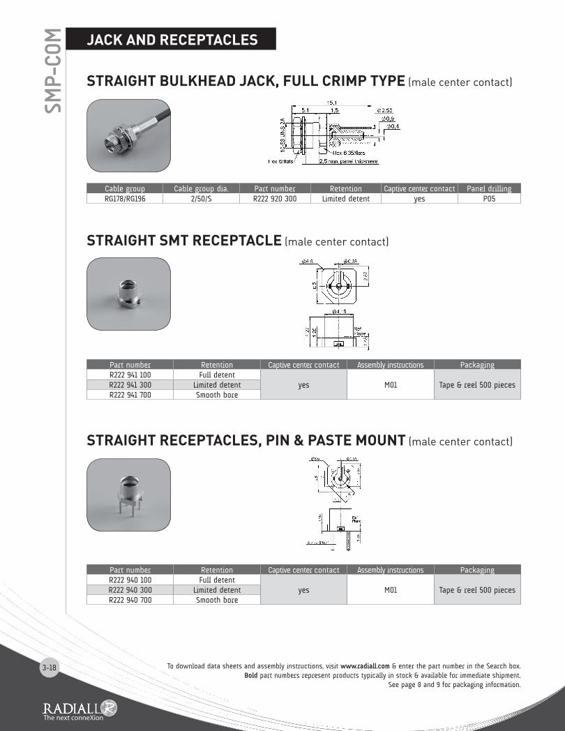
MSTRAIGHT BULKHEAD JACK, FULL CRIMP TyPE (male center contact)
STRAIGHT SMT RECEPTACLE (male center contact)
STRAIGHT RECEPTACLES, PIN & PASTE MOUNT (male center contact)
Cable group Cable group dia. Part number Retention Captive center contact Panel drillingRG178/RG196 2/50/S R222 920 300 Limited detent yes P05
Part number Retention Captive center contact Assembly instructions PackagingR222 941 100 Full detent
yes M01 Tape & reel 500 piecesR222 941 300 Limited detentR222 941 700 Smooth bore
Part number Retention Captive center contact Assembly instructions PackagingR222 940 100 Full detent
yes M01 Tape & reel 500 piecesR222 940 300 Limited detentR222 940 700 Smooth bore
To download data sheets and assembly instructions, visit www.radiall.com & enter the part number in the Search box.Bold part numbers represent products typically in stock & available for immediate shipment.
See page 8 and 9 for packaging information.

3-19
IN SERIES ADAPTER (female to female center contact)
MEASUREMENT PCB WITH SMT RECEPTACLE
Part number Finish PackagingR222 970 000 NPGR 100 pieces
Part number Packaging ConnectorR222 995 320 Unit 2 x R222 941 300
ADAPTER, MEASUREMENT PCB
PACKAGING
SMP-
COM
Part number PackagingR222 940 100
Tape & reel500 pieces
R222 940 300R222 940 700R222 941 100R222 941 300R222 941 700
A VIEW
To download data sheets and assembly instructions, visit www.radiall.com & enter the part number in the Search box.Bold part numbers represent products typically in stock & available for immediate shipment.See page 8 and 9 for packaging information.
ConnectorsR222 940 100R222 940 300R222 940 700
ConnectorsR222 941 100R222 941 300R222 941 700
A VIEW
www.radiall.com
3-20
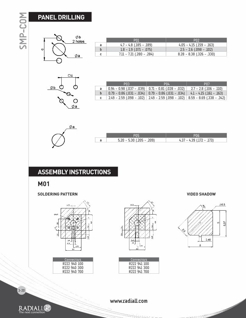
PANEL DRILLING
ASSEMBLy INSTRUCTIONS
SMP-
COM
P01 P02a 4.7 - 4.8 (.185 - .189) 4.05 - 4.15 (.159 - .163)b 1.8 - 1.9 (.071 - .075) 2.5 - 2.6 (.098 - .102)c 7.11 - 7.21 (.280 - .284) 8.28 - 8.38 (.326 - .330)
P05 P06a 5.20 - 5.30 (.205 - .209) 4.37 - 4.39 (.172 - .173)
P03 P04 P07a 0.94 - 0.98 (.037 - .039) 0.71 - 0.81 (.028 - .032) 2.7 - 2.8 (.106 - .110)b 0.79 - 0.86 (.031 - .034) 0.79 - 0.86 (.031 - .034) 4.1 - 4.15 (.161 - .163)c 2.49 - 2.59 (.098 - .102) 2.49 - 2.59 (.098 - .102) 8.59 - 8.69 (.338 - .342)
M01SOLDERING PATTERN VIDEO SHADOW
ConnectorsR222 940 100R222 940 300R222 940 700
ConnectorsR222 941 100R222 941 300R222 941 700

www.radiall.comwww.radiall.com
3-21
SMP-
MAXINTRODUCTION
GENERAL• Microminiature coaxial connectors • Power up to 300 Watts • Board to board distance misalignment of at least .078’’ (2.0 mm)• Tilt (radial misalignment): 3° minimum• 1.2 max VSWR at DC-3 GHz
APPLICATIONS• Broadcast• RF components (filters, amplifiers, ….)• Wireless communications
50Ω DC - 6 GHz
SMP-MAX Slide-on receptacle SMP-MAX In series adapter SMP-MAX Snap-on receptacle
The cost-effective solution for maximum mechanical misalignmentOf the several RF connectors available for interconnections in wireless remote radio heads, repeaters, base stations, GPS devices, and similar applications, the board to board style connector is growing in popularity. The product line has evolved from accommodating limited misalignment to offering the widest tolerances available.
SMP-MAX is introduced by RADiAll to provide larger misalignment tolerances than the early version board to board connectors like SMP or SMP-spring while offering lower cost.
Featuring an optimized interface, SMP-MAX can work up to 6 GHz board to board distance misalignment at least 2.0 mm and radial misalignment 3° minimum.
The SMP-MAX series offers 2 levels of retention provided by the receptacles:- Slide-on, for the lowest retention- Snap-on, for a positive locking with a retention
A complete SMP-MAX board to board system is made of 3 parts:
Many other custom configurations are available. larger distance misalignment and larger tilt versions are also available.

www.radiall.com
3-22
SMP-
MAX
ELECTRICAL CHARACTERISTICS Impedance 50ΩFrequency DC - 6 GHz
Typical V.S.W.R.(Board to Board connection)
Misalignment DC - 3 GHz 3-6 GHzRadial 0°, Axial 0 mm < 1.15 < 1.25
Radial 0°, Axial +/- 1 mm < 1.20 < 1.35Radial 3°, Axial 0 mm < 1.15 < 1.25
Radial 3°, Axial +/- 1 mm < 1.20 < 1.35
Insertion loss(Board to Board connection)
Misalignment DC - 3 GHz 3-6 GHzRadial 0°, Axial 0 mm 0.10 0.15
Radial 0°, Axial +/- 1 mm 0.12 0.25Radial 3°, Axial 0 mm 0.10 0.15
Radial 3°, Axial +/- 1 mm 0.12 0.25Insulation resistance 5000 MΩCenter contact resistance < 3 mΩOuter contact resistance < 1.5 mΩWorking voltage 330 VRMSDielectric withstanting voltage 1000 VRMS
Power handling (typical) > 300W @ 2.7 GHz, 25°C> 200W @ 2.7 GHz, 85°C
RF leakage -70dB to 3 GHz, axial misalignment 0mm
MECHANICAL CHARACTERISTICSMating cycles 100 cycles
Slide-on Snap-onEngagement force < 14 N < 45 NDisengagement force < 9 N > 9, < 45 NCenter contact retention force > 7 NMinimum distance between PCB 13 mmRadial misalignment tolerance 3°min
Axial misalignment tolerance 2.0 mmLarger axial misalignment version available
ENVIRONMENTAL CHARACTERISTICS Temperature range -55°C / +165°CThermal shock MIL-STD-202, method 107, condition BVibration MIL-STD-202, method 204, condition BShock MIL-STD-202, method 213, condition ACorrosion salt spray MIL-STD-202, method 101, condition BMoisture resistance MIL-STD-202, method 106
MATERIALS Body Brass/Beryllium copperMale center contact BrassFemale center contact Beryllium copperGasket Silicon rubberInsulator PTFE/PEEK
PLATING Body NPGR/BBRMale center contact NPGRFemale center contact NPGR
Test/characteristics Values/remarks
CHARACTERISTICS
Packaging = 100 pieces box / 500 pieces reel.
All dimensions are given in mm

3-23
SMP-
MAX
BULKHEAD STRAIGHT SLIDE-ON MALE JACKS FOR CABLES
STRAIGHT FEMALE PLUG FOR FLEXIBLE CABLE
RIGHT ANGLE FEMALE PLUG FOR FLEXIBLE CABLE
Cable group Cable group dia. Part number Fig Captive center contact Panel drilling PackagingRG405 .085" R222 M20 700 1
yes P01 Bulk 100 piecesRG174/RG316 2.6/50/S R222 M20 710 2
Cable group Cable group dia. Part number Captive center contact PackagingRG174/RG316 2.6/50/S R222 M80 400 yes Bulk 100 pieces
Cable group Cable group dia. Part number Captive center contact PackagingRG174/RG316 2.6/50/S R222 M80 500 yes Bulk 100 pieces
JACKS AND PLUGS
Fig. 1 Fig. 2
To download data sheets and assembly instructions, visit www.radiall.com & enter the part number in the Search box.Bold part numbers represent products typically in stock & available for immediate shipment.See page 8 and 9 for packaging information.

3-24
RECEPTACLESSM
P-M
AX
To download data sheets and assembly instructions, visit www.radiall.com & enter the part number in the Search box.Bold part numbers represent products typically in stock & available for immediate shipment.
See page 8 and 9 for packaging information.
STRAIGHT SLIDE-ON MALE RECEPTACLES
STRAIGHT SNAP-ON MALE RECEPTACLES
Part number Fig Captive center contact Panel drilling Packaging NoteR222 M00 700 1
yes
Tape & reel 500 pieces SMTR222 M00 720 2 P02 Bulk 100 pieces Solder legsR222 M00 740 3 Tape & reel 500 pieces SMTR222 M10 700 4 P01 Bulk 100 pieces Screw on
Part number Fig Captive center contact Panel drilling Packaging NoteR222 M00 080 1
yesP02
Bulk 100 piecesSolder legs
R222 M10 000 2 P01 Screw on
Fig. 1
Fig. 1
Fig. 2 Fig. 3 Fig. 4
Fig. 2

3-25
Fig. 1 Fig. 2
SMP-
Max
in-series board to board adapters
between-series board to board adapters
between-series adapters
Part number Lenght L (mm) Series PackagingR222 M40 010 9.5
SMP-MAX female / SMP-MAX female Bulk 100 piecesR222 M40 050 25.3
Part number Lenght L (mm) Series PackagingR191 996 110 12.6
SMP-MAX female / SMP femaleBulk 100 piecesR191 996 130 8.9
R191 560 000 7.5 SMP-MAX female / MMBX male snap
Part number Fig Series PackagingR191 552 000 1 SMP-MAX male / SMA female
UnitR191 553 000 2 SMP-MAX female / SMA female
adapters
To download data sheets and assembly instructions, visit www.radiall.com & enter the part number in the Search box. Bold part numbers represent products typically in stock & available for immediate shipment.See page 8 and 9 for packaging information.

www.radiall.com
3-26
PANEL DRILLINGSM
P-M
AXP01 P02
mm
A M6x0.75
A

COAXIAL, RF & MICROWAVE
2011 COMPANY PROFILESimply Your Best ConnectionRadiall is a global leader in the design, development and
manufacturing of leading edge interconnect solutions. Dedicated
to understanding its customers’ needs since 1952, Radiall has
earned the reputation of being “the best of the best” in engineering
ingenuity by providing a constant flow of creative system solutions
serving the telecommunications, aerospace, defense, instrumentation,
automotive, industrial, medical and broadcast markets.
The Best End-to-End Interconnect SolutionsWe offer an extensive range of solutions that supports the most demanding signal transmission applications.
4G wireless infrastructure, active array radars, IED’s detection, electrical wiring in aircrafts, soldier tactical radios,
in-vehicle communications networks, and magnetic resonance imaging systems are just a few of the complex
applications that we support.
Best Value-added Services• Collaboration: We work closely with your engineers to understand your business, your technical needs, and your
budgetary issues;
• Wide Product Range: We manage our product lines thru the entire lifecycle in order to offer you a wide selection of
standard products at an affordable cost;
• Custom Products: We can tailor products to specific equipment and application needs;
• Global Presence: We’re everywhere you need us, with worldwide sales, engineering support, R&D in North America,
Europe, and Asia, and manufacturing facilities strategically located in the United States, Mexico, France, India, and China;
• Responsive Support and Service: From the design stage, planning to post-installation support, we’re with you at every
step, whether you need sales support or engineering expertise;
• On-time Delivery: We support your logistical needs so you get the products when and where you need them;
• Warranty: We proudly stand behind our products.
Certifications and EnvironmentalRadiall is ISO 9001: 2008 certified and dedicated to continuous improvement
programs that have resulted in also being AS9100, TS16949 and ISO 14001
certified. In addition, Radiall is committed to investing in its people, future
technologies and the environment, such as being RoHS (Restriction of Hazardous Substances) and REACH (Registration,
Evaluation, Authorization and Restriction of Chemical substances) compliant.
• RF coaxial connectors• Fiber optic connectors and transceivers• Coaxial and fiber optic cable assemblies and harnesses• High frequency microwave components• Coaxial switches, including the smallest and most reliable SPDT relay
• Multipin rectangular connectors• Rack and panel connectors• Antennas for tactical networks, aerospace and instrumentation
Technical information and sales contacts are available at : www.radiall.com
www.radiall.com
COAXIAL, RF & MICROWAVEFull Line Catalog
www.radiall.com
Cable designation
Cable Group / Ω
Imp.Ω
Cable dimensions mm (inch) Radiall cable if applicable
Core type Core Insulator Screen Outer P/N RemarkRG 174 A/U 2.6 / 50 S 50 7 x 0.16 0.48 (.019) 1.52 (.060) S 2.79 (.110) C291 150 000 PVC jacketRG 178 B/U 2 / 50 S 50 7 x 0.1 0.30 (.012) 0.84 (.033) S 1.78 (.070) C291 145 007 FEP jacketRG 178 B/U 2 / 50 S 50 7 x 0.1 0.30 (.012) 0.84 (.033) S 1.83 (.072) C291 145 060 PVC jacketRG 178 non m. 2 / 50 S 50 7 x 0.1 0.29 (.011) 0.84 (.033) S 1.80 (.071) C291 140 087 non magnetic / FEP jacketRG 179 B/U 2.6 / 75 S 75 7 x 0.1 0.30 (.012) 1.60 (.063) S 2.54 (.010) C291 210 007 FEP jacketRG 187 A/U 2.6 / 75 S 75 7 x 0.1 0.30 (.012) 1.60 (.063) S 2.79 (.110) C291 211 006 PTFE jacketRG 188 A/U 2.6 / 50 S 50 7 x 0.17 0.51 (.020) 1.52 (.060) S 2.79 (.110) C291 160 006 PTFE jacketRG 196 A/U 2 / 50 S 50 7 x 0.1 0.30 (.012) 0.86 (.034) S 2.03 (.080) C291 110 006 PTFE jacketRG 212 /U 8 / 50 D 50 solid 1.41 (.056) 4.70 (.185) D 8.43 (.331) naRG 213 /U 10 / 50 S 50 7 x 0.75 2.26 (.089) 7.24 (.285) S 10.30 (.406) C291 510 000 PVC jacketRG 214 /U 11 / 50 D 50 7 x 0.75 2.25 (.089) 7.24 (.285) D 10.80 (.425) C291 600 000 PVC jacket
RG 215 10 / 50 S 50 7 x 0.75 2.25 (.089) 7.25 (.285) S 10.29 (.405) naRG 216 /U 11 / 75 D 75 7 x 0.4 1.21 (.048) 7.24 (.285) D 10.80 (.425) C291 610 000 PVC jacketRG 217 /U 14 / 50 D 50 solid 2.69 (.106) 9.40 (.370) D 13.84 (.545) C291 620 000 PVC jacketRG 218 /U 22 / 50 S 50 solid 4.95 (.195) 17.27 (.680) S 22.10 (.870) C291 630 000 PVC jacketRG 223 /U 5 / 50 D 50 solid 0.89 (.035) 2.95 (.116) D 5.38 (.212) C291 330 000 PVC jacketRG 225 /U 11 / 50 D 50 7 x 0.8 2.38 (.094) 7.24 (.285) D 10.90 (.429) C291 605 007 glass fiber jacketRG 303 /U 5 / 50 S 50 solid 0.94 (.037) 2.95 (.116) S 4.32 (.170) naRG 316 /U 2.6 / 50 S 50 7 x 0.17 0.53 (.021) 1.52 (.060) S 2.49 (.098) C291 170 007 FEP jacket
RD 316 2.6 / 50 D 50 7 x 0.17 0.53 (.021) 1.52 (.060) D 2.80 (.110) C291 185 067 FEP jacketRG 393 10 / 50 D 50 7 x 0.81 2.39 (.094) 7.24 (.285) D 9.91 (.390) C291 511 007 FEP jacketRG 400 5 / 50 / D 50 19 x 0.19 0.98 (.039) 2.95 (.116) D 4.95 (.195) C291 324 007 FEP jacket
Flexible cable BT approvedRD 179 2.6 / 75 D 75 7 x 0.10 0.30 (.012) 1.6 (.063) D 3.07 (.121) C291 230 080 LSOH jacketBT 3002 3.6 / 75 D 75 solid 0.31 (.012) 1.95 (.077) D 3.55 (.140) C291 246 046 FEP jacketBT 2002 5 / 75 D 75 7 x 0.20 0.60 (.024) 2.5 (.098) D 5.1 (.200) C291 333 080 FEP jacket
Semi rigid cables MIL-C-17 standardRG 401 /U .250" 50 solid 1.63 (.064) 5.31 (.209) -- 6.35 (.250) C291 870 001 copper tubingRG 401 alu .250" 50 solid 1.63 (.064) 5.31 (.209) -- 6.35 (.250) C291 874 187 tinned alu tubingRG 402 /U .141" 50 solid 0.92 (.036) 2.98 (.117) -- 3.58 (.141) C291 860 001 copper tubingRG 402 tin .141" 50 solid 0.92 (.036) 2.98 (.117) -- 3.58 (.141) C291 862 005 tinned copper tubingRG 402 silver .141" 50 solid 0.92 (.036) 2.98 (.117) -- 3.58 (.141) C291 861 066 silvered copper tubingRG 402 alu .141" 50 solid 0.92 (.036) 2.98 (.117) -- 3.58 (.141) C291 864 187 tinned alu tubing
RG 402 non m. .141" 50 solid 0.92 (.036) 2.98 (.117) -- 3.58 (.141) C291 861 061 non magnetic / copper tubingRG 405 /U .085" 50 solid 0.51 (.020) 1.68 (.066) -- 2.20 (.087) C291 850 001 copper tubingRG 405 tin .085" 50 solid 0.51 (.020) 1.68 (.066) -- 2.20 (.087) C291 850 005 tinned copper tubingRG 405 alu .085" 50 solid 0.51 (.020) 1.68 (.066) -- 2.20 (.087) C291 844 187 tinned alu tubing
RG 405 non m. .085" 50 solid 0.51 (.020) 1.68 (.066) -- 2.20 (.087) C291 851 001 non magnetic / copper tubing.047" .047" 50 solid 0.29 (.011) 0.94 (.037) -- 1.19 (.047) C291 855 001 copper tubing
.047" tin .047" 50 solid 0.29 (.011) 0.94 (.037) -- 1.19 (.047) C291 855 065 tinned copper tubingHand-formable cable
Hand-formable .085" 50 solid 0.51 (.020) 1.63 (.064) -- 2.21 (.087) C291 844 065 tin soaked braidHand-formable .141" 50 solid 0.92 (.036) 2.95 (.116) -- 3.50 (.138) C291 864 065 tin soaked braidHand-formable .141" 50 solid 0.92 (.036) 2.98 (.117) -- 4.05 (.159) C291 866 378 FEP jacketHand-formable .141" 50 solid 0.92 (.036) 2.98 (.117) -- 4.50 (.177) C291 866 270 LSZH jacket
Corrugated cables (with helical or ringed/annular copper tube)Flexible 1/4" 50 solid 2.38 (.094) 6.40 (.252) -- 8.70 (.343) na ringed/annular tubeFlexible 1/2" 50 solid 4.80 (.189) 11.6 (.457) -- 16.35 (.644) C291 972 085 ringed/annular tubeFlexible 7/8" 50 solid 9.13 (.359) 22.5 (.866) -- 27.7 (1.091) na ringed/annular tubeFlexible 1 1/4" 50 solid 12.7 (.500) 32.5 (1.28) -- 39.5 (1.55) na ringed/annular tubeFlexible 1 5/8" 50 solid 17.3 (.681) 43.5 (1.71) -- 50.5 (1.99) na ringed/annular tube
Super flexible 1/4" 50 solid 1.90 (.075) 4.70 (.185) -- 7.40 (.291) C291 993 080 helical tubeSuper flexible 3/8" 50 solid 2.60 (.102) 6.30 (.248) -- 10.8 (.425) C291 996 070 helical tubeSuper flexible 1/2" 50 solid 3.60 (.142) 8.70 (.343) -- 13.2 (.520) C291 994 080 helical tubeSuper flexible 7/8" 50 tube 9.04 (.356) 23.62 (.930) -- 27.48 (1.082) C291 996 580 helical tube
Note: S = single braid. D = dual braid. For more information about cables manufactured by Radiall, please consult our online catalog.
www.radiall.com
D1C
004X
E -
2010
Nov
embe
r Ed
ition
AEROspace AUTOMOTIVE DEFENSE INDUSTRIAL INSTRUMENTATION SPACE TELECOMMEDICAL
India - RADIALL India Pvt. Ltd
S.A.
.
.
.
.
Poi
ntVi
rgul
e +3
3 3
44 2
3 48
48