Smith Meter AccuLoadinfo.smithmeter.com/literature/docs/mn06146.pdf · Smith Meter® AccuLoad ......
20
The Most Trusted Name In Measurement Electronic Preset Delivery System Smith Meter ® AccuLoad ® Tank Proving Guide Bulletin MN06146 Issue/Rev. 0.1 (7/10)
Transcript of Smith Meter AccuLoadinfo.smithmeter.com/literature/docs/mn06146.pdf · Smith Meter® AccuLoad ......

The Most Trusted Name In Measurement
Electronic Preset Delivery System
Smith Meter® AccuLoad® Tank Proving Guide
Bulletin MN06146
Issue/Rev. 0.1 (7/10)
Caution
The default or operating values used in this manual and in the program of the AccuLoad III are for factory testing only and should not be construed as default or operating values for your metering system. Each metering system is unique and each program parameter must be reviewed and programmed for that specific metering system application.
Disclaimer
FMC Technologies Measurement Solutions, Inc. hereby disclaims any and all responsibility for damages, including but not limited to consequential damages, arising out of or related to the inputting of incorrect or improper program or default values entered in connection with the AccuLoad III.
Table of Contents
i
Section I – Introduction .............................................................................................................................................. 1 Introduction ............................................................................................................................................................ 1
AccuLoad I .......................................................................................................................................................... 1 AccuLoad II and III ............................................................................................................................................. 1
How to Use This Manual ........................................................................................................................................ 1 Before Beginning to Prove ..................................................................................................................................... 2
Section II – System Pressure Requirements ............................................................................................................. 3 Section III – Flow Rate Selection ............................................................................................................................... 4 Section IV – Factor Selection for Preliminary Proving ............................................................................................... 5
Establishing Factor (New Meter) ............................................................................................................................ 5 AccuLoad I ............................................................................................................................................................. 5 Remember the Rules ............................................................................................................................................. 6 AccuLoad II and AccuLoad III ................................................................................................................................ 6 Remember the Rules ............................................................................................................................................. 7 Reproving the Meter .............................................................................................................................................. 7
Section V – Factor Optimizing ................................................................................................................................... 8
AccuLoad I ........................................................................................................................................................... 10 AccuLoad II .......................................................................................................................................................... 11
Section VI – AccuLoad III Automated Proving Mode .............................................................................................. 12
Automated Proving Mode ................................................................................................................................. 12


Section I – Introduction
MN06146 Issue/Rev. 0.1 (7/10) 1
Introduction The purpose of this document is to describe a me-thod for proving an AccuLoad/meter system with a volumetric tank prover. Other methods may be ap-propriate under certain circumstances. It is not poss-ible to discuss herein all of the procedures, stan-dards, and knowledge required for meter proving. It is assumed that the individuals performing these ca-libration tests are qualified to do so and have par-ticular familiarity with the following where applicable:
1. Operation of Smith Meter AccuLoad products, meters, and valves
2. API Manual of Petroleum Measurement, Chap-ter 4, Proving Systems
3. NCWM Handbook 44, Sections 1 and 3
4. Any additional local codes and standards, both governmental and private.
For the purpose of this document, the term “AccuL-oad I” will refer to the original Smith Meter AccuLoad electronic preset, which was one electronic preset in one enclosure. The term “AccuLoad II” will refer to the electronic preset that was released in 1989 and was manufactured through 2001. The term “AccuL-oad III” will refer to the electronic presets manufac-tured from 1999 to the present. The term “AccuLoad” will be used as a general term when referring to any of these systems.
The type of proving described will be “gross to gross”; that is, no temperature correction is made to the liquid. This is allowed because the temperature at the meter is considered the same as that in the tank prover; hence, the corrections for each would cancel each other. The temperature correction to be applied will be to the tank prover. It is a function of the tank material (usually carbon steel or stainless steel) and the temperature difference between the proving temperature and the prover’s certified wa-terdraw calibration temperature (usually 60oF). Note: When using automated proving mode in AccuLoad III, the meter factors are calculated using temperature compensation as described in Section VI.
AccuLoad I AccuLoad I has the ability to automatically switch to a unique calibration factor for each of the four differ-ent flow rate ranges, thus linearizing the meter out-put. When initially proving an AccuLoad I system, “lock in” each flow rate and determine a calibration factor for each. These calibration factors are then
programmed into the AccuLoad and typical flow runs are executed, including normal low flow start, high flow, and multi-step valve closure. The goal is to demonstrate satisfactory correlation between the displayed volume (AccuLoad register) and volume actually delivered (Tank Prover).
AccuLoad II and III The proving procedure for the AccuLoad II and III systems is similar to that of AccuLoad I, except that
1. AccuLoad II and III use meter factors in lieu of calibration factors (see Section IV)
2. AccuLoad II and III continuously linearize the meter output by applying the meter factor at the flow rate the system is operating. They do not switch to the factor programmed, but calculate and use the meter factor for flow rates between those that are programmed.
The maximum allowable deviation between the Ac-cuLoad register and the tank prover reading must be agreed upon and understood by all parties con-cerned before meter proving operations begin.
How to Use This Manual This manual is to be used for reference when tank proving metering systems that contain the AccuLoad electronic preset.
This manual is divided into seven sections: Introduc-tion, System Pressure Requirements, Flow Rate Se-lection, Factor Selection for Preliminary Proving, Factor Optimizing, AccuLoad III Automated Proving Mode, and Appendix.
“System Pressure Requirements” describes the back pressure requirements to prevent cavitation at the meter during the proving process.
“Flow Rate Selection” describes the flow rates that are typically used for proving a metering system.
“Factor Selection for Preliminary Proving” describes the formulas used to establish the preliminary factors for the AccuLoads. Examples are also provided for determining factors for turbine meters and positive displacement meters.
“Factor Optimizing” describes the steps required to optimize the preliminary factors into final factors that will be used for loading the product.
Section I – Introduction
MN06146 Issue/Rev. 0.1 (7/10) 2
“AccuLoad III Automated Proving Mode” describes a feature which allows the operator to prove the meter on all four products, with four meter factors and as-sociated flow rates for each product, without having to enter the program mode for each product and me-ter factor.
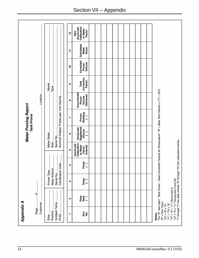
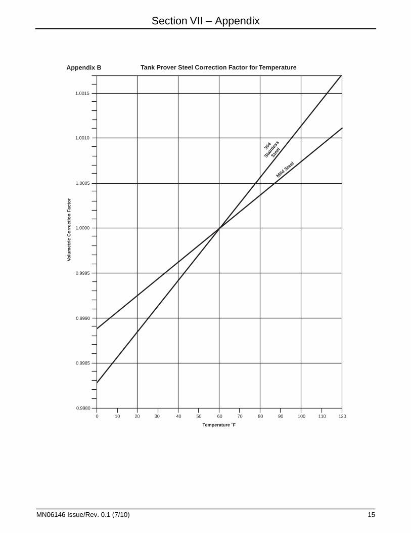
“Appendix” includes a Meter Proving Report form and a Tank Prover Steel Correction Factor for Tem-perature chart.
The examples presented in this manual are for clari-ty and convenience. The values will vary from one particular installation and/or operation to another.
Before Beginning to Prove Be sure that the AccuLoad is functioning properly and that the operator has read and understands the instructions contained in this manual.

Section II – Pressure System Requirements
MN06146 Issue/Rev. 0.1 (7/10) 3
For accurate measurement, adequate back pressure at the meter is required to prevent cavitation. For a turbine meter at its maximum rated flow, this will be approximately 20 psi plus the vapor pressure of the product being metered (e.g., about 15-20 psig for gasoline). For a positive displacement meter, 5 psi plus vapor pressure (e.g., about 0-5 psig for gaso-line) is sufficient. Back pressure may be a problem at the maximum flow rate if system pressure loss
downstream of the meter is quite low. This is most likely to occur, particularly in a turbine meter system, if the set stop valve goes to a wide open position (i.e., is not controlling flow).
With a pressure gauge between the meter and valve, adequate meter back pressure during proving may be verified.

Section III – Flow Rate Selection
MN06146 Issue/Rev. 0.1 (7/10) 4
The flow rates typically selected for proving are the same as those used in the normal loading operation.
Q1: First High Flow Rate – Maximum Rate
Q2: Second High Flow Rate – Only used for loading smaller tanks where Q1 would be too high a rate
Q3: Low Flow Start Flow Rate – To minimize splash-ing and/or foaming within the truck tanks
Q4: Minimum Flow Rate – Flow rate during the final stage of loading
To reduce proving time and still retain most of the improved accuracy obtainable with meter lineariza-tion, proving may be limited to just two flow rates: Q1 and Q3.
Section IV – Factor Selection for Preliminary Proving
MN06146 Issue/Rev. 0.1 (7/10) 5
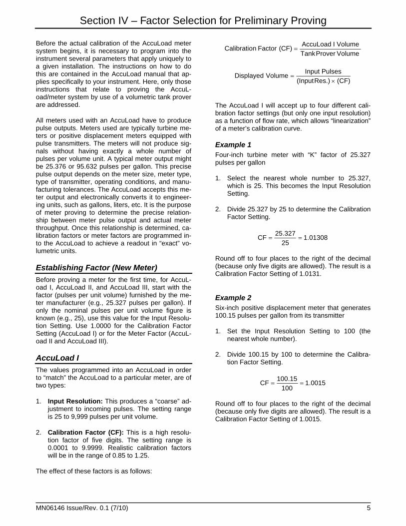
Before the actual calibration of the AccuLoad meter system begins, it is necessary to program into the instrument several parameters that apply uniquely to a given installation. The instructions on how to do this are contained in the AccuLoad manual that ap-plies specifically to your instrument. Here, only those instructions that relate to proving the AccuL-oad/meter system by use of a volumetric tank prover are addressed.
All meters used with an AccuLoad have to produce pulse outputs. Meters used are typically turbine me-ters or positive displacement meters equipped with pulse transmitters. The meters will not produce sig-nals without having exactly a whole number of pulses per volume unit. A typical meter output might be 25.376 or 95.632 pulses per gallon. This precise pulse output depends on the meter size, meter type, type of transmitter, operating conditions, and manu-facturing tolerances. The AccuLoad accepts this me-ter output and electronically converts it to engineer-ing units, such as gallons, liters, etc. It is the purpose of meter proving to determine the precise relation-ship between meter pulse output and actual meter throughput. Once this relationship is determined, ca-libration factors or meter factors are programmed in-to the AccuLoad to achieve a readout in “exact” vo-lumetric units.
Establishing Factor (New Meter) Before proving a meter for the first time, for AccuL-oad I, AccuLoad II, and AccuLoad III, start with the factor (pulses per unit volume) furnished by the me-ter manufacturer (e.g., 25.327 pulses per gallon). If only the nominal pulses per unit volume figure is known (e.g., 25), use this value for the Input Resolu-tion Setting. Use 1.0000 for the Calibration Factor Setting (AccuLoad I) or for the Meter Factor (AccuL-oad II and AccuLoad III).
AccuLoad I The values programmed into an AccuLoad in order to “match” the AccuLoad to a particular meter, are of two types:
1. Input Resolution: This produces a “coarse” ad-justment to incoming pulses. The setting range is 25 to 9,999 pulses per unit volume.
2. Calibration Factor (CF): This is a high resolu-tion factor of five digits. The setting range is 0.0001 to 9.9999. Realistic calibration factors will be in the range of 0.85 to 1.25.
The effect of these factors is as follows:
VolumeProverTankVolumeIAccuLoad
(CF)FactornCalibratio
(CF)Res.)(InputPulsesInput
VolumeDisplayed
The AccuLoad I will accept up to four different cali-bration factor settings (but only one input resolution) as a function of flow rate, which allows “linearization” of a meter’s calibration curve.
Example 1 Four-inch turbine meter with “K” factor of 25.327 pulses per gallon
1. Select the nearest whole number to 25.327, which is 25. This becomes the Input Resolution Setting.
2. Divide 25.327 by 25 to determine the Calibration Factor Setting.
01308.125327.25
CF
Round off to four places to the right of the decimal (because only five digits are allowed). The result is a Calibration Factor Setting of 1.0131.
Example 2 Six-inch positive displacement meter that generates 100.15 pulses per gallon from its transmitter
1. Set the Input Resolution Setting to 100 (the nearest whole number).
2. Divide 100.15 by 100 to determine the Calibra-tion Factor Setting.
0015.1100
15.100CF
Round off to four places to the right of the decimal (because only five digits are allowed). The result is a Calibration Factor Setting of 1.0015.
Section IV – Factor Selection for Preliminary Proving
MN06146 Issue/Rev. 0.1 (7/10) 6
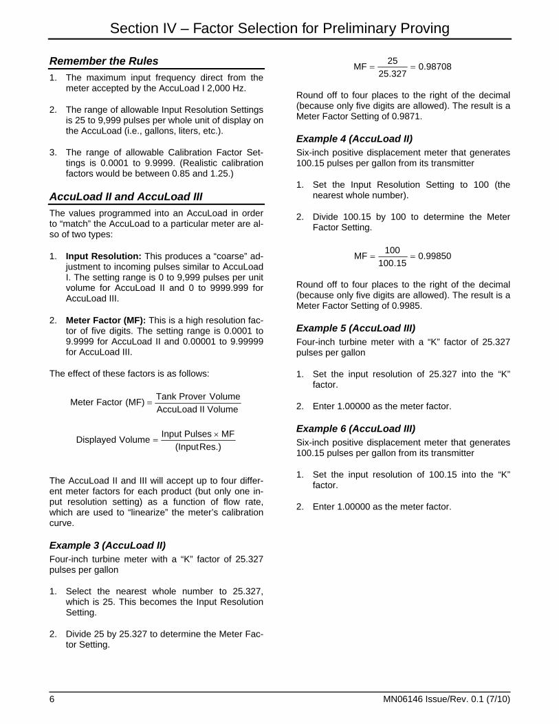
Remember the Rules 1. The maximum input frequency direct from the
meter accepted by the AccuLoad I 2,000 Hz.
2. The range of allowable Input Resolution Settings is 25 to 9,999 pulses per whole unit of display on the AccuLoad (i.e., gallons, liters, etc.).
3. The range of allowable Calibration Factor Set-tings is 0.0001 to 9.9999. (Realistic calibration factors would be between 0.85 and 1.25.)
AccuLoad II and AccuLoad III The values programmed into an AccuLoad in order to “match” the AccuLoad to a particular meter are al-so of two types:
1. Input Resolution: This produces a “coarse” ad-justment to incoming pulses similar to AccuLoad I. The setting range is 0 to 9,999 pulses per unit volume for AccuLoad II and 0 to 9999.999 for AccuLoad III.
2. Meter Factor (MF): This is a high resolution fac-tor of five digits. The setting range is 0.0001 to 9.9999 for AccuLoad II and 0.00001 to 9.99999 for AccuLoad III.
The effect of these factors is as follows:
VolumeIIAccuLoadVolumeProverTank
(MF)FactorMeter
Res.)(InputMFPulsesInput
VolumeDisplayed
The AccuLoad II and III will accept up to four differ-ent meter factors for each product (but only one in-put resolution setting) as a function of flow rate, which are used to “linearize” the meter’s calibration curve.
Example 3 (AccuLoad II) Four-inch turbine meter with a “K” factor of 25.327 pulses per gallon
1. Select the nearest whole number to 25.327, which is 25. This becomes the Input Resolution Setting.
2. Divide 25 by 25.327 to determine the Meter Fac-tor Setting.
98708.0327.25
25MF
Round off to four places to the right of the decimal (because only five digits are allowed). The result is a Meter Factor Setting of 0.9871.
Example 4 (AccuLoad II) Six-inch positive displacement meter that generates 100.15 pulses per gallon from its transmitter
1. Set the Input Resolution Setting to 100 (the nearest whole number).
2. Divide 100.15 by 100 to determine the Meter Factor Setting.
99850.015.100
100MF
Round off to four places to the right of the decimal (because only five digits are allowed). The result is a Meter Factor Setting of 0.9985.
Example 5 (AccuLoad III) Four-inch turbine meter with a “K” factor of 25.327 pulses per gallon
1. Set the input resolution of 25.327 into the “K” factor.
2. Enter 1.00000 as the meter factor.
Example 6 (AccuLoad III) Six-inch positive displacement meter that generates 100.15 pulses per gallon from its transmitter
1. Set the input resolution of 100.15 into the “K” factor.
2. Enter 1.00000 as the meter factor.

Section IV – Factor Selection for Preliminary Proving
MN06146 Issue/Rev. 0.1 (7/10) 7
Remember the Rules 1. The maximum input frequency accepted by Ac-
cuLoad II directly from the meter is 3,000 Hz. The maximum input frequency accepted by Ac-cuLoad III directly from the meter is 10,000 Hz.
2. The range of allowable Input Resolution Settings is 0 to 9,999 pulses per whole unit of display (i.e., gallons, liters, etc.) on the AccuLoad II, and 0 to 99999.999 on the AccuLoad III.
3. The range of allowable Meter Factor Settings is 0.0001 to 9.9999 for the AccuLoad II and 0.00001 to 9.99999 for the AccuLoad III. Realis-tic Meter Factors would be between 0.85 and 1.25.
Reproving the Meter If reproving the system, use the factors already set into the AccuLoad and proceed to the next section, Factor Optimizing.

Section V – Factor Optimizing
MN06146 Issue/Rev. 0.1 (7/10) 8
Start at Q1, the Maximum Flow Rate. Use the Input Resolution Setting and Factor Setting determined previously. Use Smith Form “Meter Proving Report,” which is Appendix A of this manual, or an equivalent form to record all data.
Note: The term “Factor” in this section refers to the Calibration Factor if used with an AccuLoad II or AccuLoad III.
Step 1 Reprogram the AccuLoad as follows to obtain the fac-tor at Q1:
1. Set the Minimum Flow Rate.
2. Set the Low Flow Start to “yes.”
3. Set the Low Flow Start Volume at about 5% of the tank prover volume (to reduce splashing on start-up).
4. Set the Low Flow Start Rate at about 0.5 times Q1 value.
5. Set the High Flow Rate.
6. Check that the flow tolerance is in proper range, typically 5% to 9%.
7. Set the First Trip Volume at a minimum value, typically 5% to 8% of Q1. Example: For Q1 of 500 gpm, set at 25 to 40. Reset later to normal opera-tion when final proving in Step 23.
8. Check the Final Trip Volume. Set to 1.5 (reset later when final proving in Step 23).
9. Set the Input Resolution to the Input Resolution Setting determined above.
10. Set Flow Rate Number 1 to zero (0000). Set Fac-tor Number 1 to the Factor Setting previously de-termined.
11. Set Proving Mode Select to W&M Proving.
Step 2 Start proving runs.
1. Return to Run Mode.
2. If a First/Second High Flow Switch is used, make certain the switch is in First High Flow Position (Q1).
3. Preset Tank Prover Volume.
4. Press “Start” to fill prover.
Step 3 Wet down the prover and stabilize the temperature of the meter/prover system. Fill and drain the prover once or twice until the measured liquid temperatures at meter and prover are equal within 1° to 2°F. Also, confirm that excessive splashing or foaming does not occur at this high flow rate. If it does, reduce the flow rate and/or increase the duration of the brief low flow start to the minimum amount needed to eliminate the problem.
Note: Typically after each proving run, before closing the prover drain valve, allow the prover to drain down for exactly 30 seconds after solid flow has broken to maintain a consistent “clingage vo-lume” in the prover.
Step 4 Now start an additional proving run to determine the meter factor. Determine the meter factor (MF) at Q1. The meter factor is determined from the actual tank prover reading and the AccuLoad volume registered.
VolumeRegisteredVolumeProverTankActual
MF
Example: 1,000 gallon tank prover Actual Tank Reading: 999.65 gallons AccuLoad Reading: 999.9 gallons
9997.09.999
65.999MF
Note: Typically, tank provers read in ± cubic inches, one gallon = 231 cubic inches.
Step 5 Check the repeatability of MF at Q1. Make one to four repeat runs to determine:
1. Repeatability 2. Average Meter Factor (MF) Example: MF = 0.9997 0.9998 0.9996 0.9997 Average MF = 0.9997 Step 6 (AccuLoad I Only) Compute and enter the new Calibration Factor (CF) at Q1:
Section V – Factor Optimizing
MN06146 Issue/Rev. 0.1 (7/10) 9
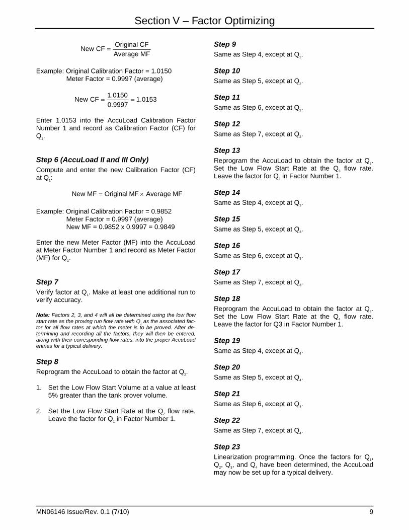
MFAverageCFOriginal
CFNew
Example: Original Calibration Factor = 1.0150 Meter Factor = 0.9997 (average)
0153.10.99971.0150
CFNew
Enter 1.0153 into the AccuLoad Calibration Factor Number 1 and record as Calibration Factor (CF) for Q1. Step 6 (AccuLoad II and III Only) Compute and enter the new Calibration Factor (CF) at Q1:
MFAverageMFOriginalMFNew
Example: Original Calibration Factor = 0.9852 Meter Factor = 0.9997 (average) New MF = 0.9852 x 0.9997 = 0.9849 Enter the new Meter Factor (MF) into the AccuLoad at Meter Factor Number 1 and record as Meter Factor (MF) for Q1.
Step 7 Verify factor at Q1. Make at least one additional run to verify accuracy.
Note: Factors 2, 3, and 4 will all be determined using the low flow start rate as the proving run flow rate with Q1 as the associated fac-tor for all flow rates at which the meter is to be proved. After de-termining and recording all the factors, they will then be entered, along with their corresponding flow rates, into the proper AccuLoad entries for a typical delivery.
Step 8 Reprogram the AccuLoad to obtain the factor at Q2.
1. Set the Low Flow Start Volume at a value at least 5% greater than the tank prover volume.
2. Set the Low Flow Start Rate at the Q2 flow rate. Leave the factor for Q1 in Factor Number 1.
Step 9 Same as Step 4, except at Q2.
Step 10 Same as Step 5, except at Q2.
Step 11 Same as Step 6, except at Q2.
Step 12 Same as Step 7, except at Q2.
Step 13 Reprogram the AccuLoad to obtain the factor at Q2. Set the Low Flow Start Rate at the Q3 flow rate. Leave the factor for Q2 in Factor Number 1.
Step 14 Same as Step 4, except at Q3.
Step 15 Same as Step 5, except at Q3.
Step 16 Same as Step 6, except at Q3.
Step 17 Same as Step 7, except at Q3.
Step 18 Reprogram the AccuLoad to obtain the factor at Q4. Set the Low Flow Start Rate at the Q4 flow rate. Leave the factor for Q3 in Factor Number 1.
Step 19 Same as Step 4, except at Q4.
Step 20 Same as Step 5, except at Q4.
Step 21 Same as Step 6, except at Q4.
Step 22 Same as Step 7, except at Q4.
Step 23 Linearization programming. Once the factors for Q1, Q2, Q3, and Q4 have been determined, the AccuLoad may now be set up for a typical delivery.
Section V – Factor Optimizing
MN06146 Issue/Rev. 0.1 (7/10) 10
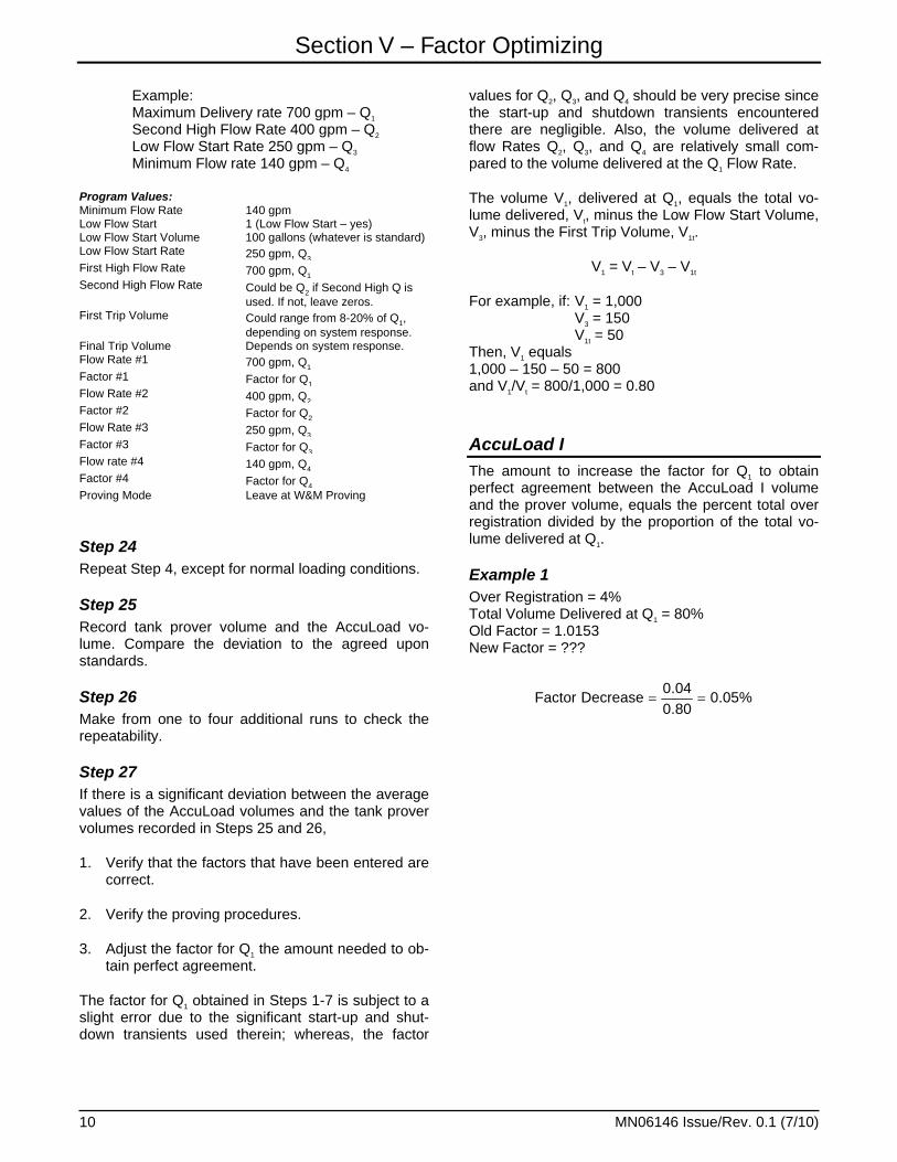
Example: Maximum Delivery rate 700 gpm – Q1 Second High Flow Rate 400 gpm – Q2 Low Flow Start Rate 250 gpm – Q3 Minimum Flow rate 140 gpm – Q4
Program Values: Minimum Flow Rate 140 gpm Low Flow Start 1 (Low Flow Start – yes) Low Flow Start Volume 100 gallons (whatever is standard) Low Flow Start Rate 250 gpm, Q3 First High Flow Rate 700 gpm, Q1 Second High Flow Rate Could be Q2 if Second High Q is
used. If not, leave zeros. First Trip Volume Could range from 8-20% of Q1,
depending on system response. Final Trip Volume Depends on system response. Flow Rate #1 700 gpm, Q1 Factor #1 Factor for Q1 Flow Rate #2 400 gpm, Q2 Factor #2 Factor for Q2 Flow Rate #3 250 gpm, Q3 Factor #3 Factor for Q3 Flow rate #4 140 gpm, Q4 Factor #4 Factor for Q4 Proving Mode Leave at W&M Proving
Step 24 Repeat Step 4, except for normal loading conditions.
Step 25 Record tank prover volume and the AccuLoad vo-lume. Compare the deviation to the agreed upon standards.
Step 26 Make from one to four additional runs to check the repeatability.
Step 27 If there is a significant deviation between the average values of the AccuLoad volumes and the tank prover volumes recorded in Steps 25 and 26,
1. Verify that the factors that have been entered are correct.
2. Verify the proving procedures.
3. Adjust the factor for Q1 the amount needed to ob-tain perfect agreement.
The factor for Q1 obtained in Steps 1-7 is subject to a slight error due to the significant start-up and shut-down transients used therein; whereas, the factor
values for Q2, Q3, and Q4 should be very precise since the start-up and shutdown transients encountered there are negligible. Also, the volume delivered at flow Rates Q2, Q3, and Q4 are relatively small com-pared to the volume delivered at the Q1 Flow Rate.
The volume V1, delivered at Q1, equals the total vo-lume delivered, Vt, minus the Low Flow Start Volume, V3, minus the First Trip Volume, V1t.
V1 = Vt – V3 – V1t
For example, if: V1 = 1,000 V3 = 150 V1t = 50 Then, V1 equals 1,000 – 150 – 50 = 800 and V1/Vt = 800/1,000 = 0.80
AccuLoad I The amount to increase the factor for Q1 to obtain perfect agreement between the AccuLoad I volume and the prover volume, equals the percent total over registration divided by the proportion of the total vo-lume delivered at Q1.
Example 1 Over Registration = 4% Total Volume Delivered at Q1 = 80% Old Factor = 1.0153 New Factor = ???
%05.080.004.0
DecreaseFactor
Section V – Factor Optimizing
MN06146 Issue/Rev. 0.1 (7/10) 11
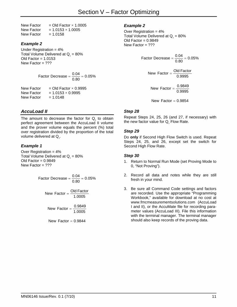
New Factor = Old Factor × 1.0005 New Factor = 1.0153 × 1.0005 New Factor = 1.0158
Example 2 Under Registration = 4% Total Volume Delivered at Q1 = 80% Old Factor = 1.0153 New Factor = ???
%05.080.004.0
DecreaseFactor
New Factor = Old Factor × 0.9995 New Factor = 1.0153 × 0.9995 New Factor = 1.0148 AccuLoad II The amount to decrease the factor for Q1 to obtain perfect agreement between the AccuLoad II volume and the prover volume equals the percent (%) total over registration divided by the proportion of the total volume delivered at Q1.
Example 1 Over Registration = 4% Total Volume Delivered at Q1 = 80% Old Factor = 0.9849 New Factor = ???
%05.080.004.0
DecreaseFactor
1.0005FactorOld
FactorNew
1.00059849.0
FactorNew
9844.0FactorNew
Example 2 Over Registration = 4% Total Volume Delivered at Q1 = 80% Old Factor = 0.9849 New Factor = ???
%05.080.004.0
DecreaseFactor
0.9995FactorOld
FactorNew
0.99959849.0
FactorNew
9854.0FactorNew
Step 28 Repeat Steps 24, 25, 26 (and 27, if necessary) with the new factor value for Q1 Flow Rate.
Step 29 Do only if Second High Flow Switch is used. Repeat Steps 24, 25, and 26, except set the switch for Second High Flow Rate.
Step 30 1. Return to Normal Run Mode (set Proving Mode to
0, “Not Proving”).
2. Record all data and notes while they are still fresh in your mind.
3. Be sure all Command Code settings and factors are recorded. Use the appropriate “Programming Workbook,” available for download at no cost at www.fmcmeasurementsolutions.com (AccuLoad I and II), or the AccuMate file for recording para-meter values (AccuLoad III). File this information with the terminal manager. The terminal manager should also keep records of the proving data.
Section VI – AccuLoad III Automated Proving Mode
MN06146 Issue/Rev. 0.1 (7/10) 12
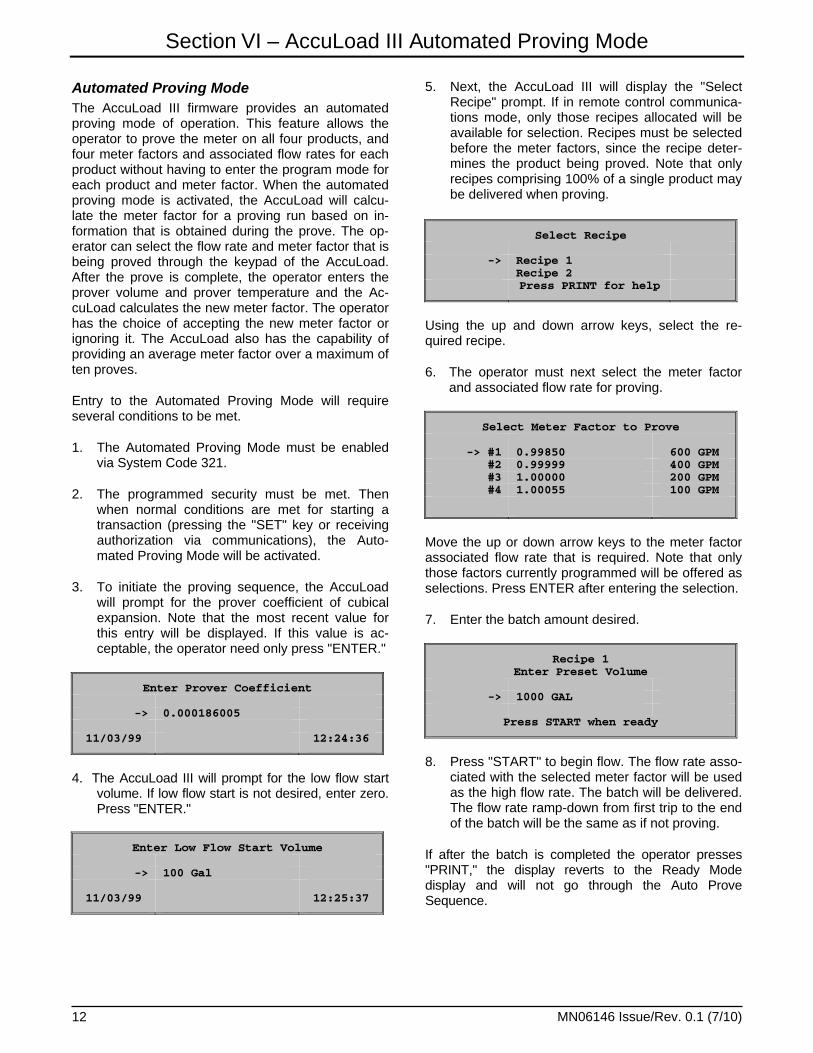
Automated Proving Mode The AccuLoad III firmware provides an automated proving mode of operation. This feature allows the operator to prove the meter on all four products, and four meter factors and associated flow rates for each product without having to enter the program mode for each product and meter factor. When the automated proving mode is activated, the AccuLoad will calcu-late the meter factor for a proving run based on in-formation that is obtained during the prove. The op-erator can select the flow rate and meter factor that is being proved through the keypad of the AccuLoad. After the prove is complete, the operator enters the prover volume and prover temperature and the Ac-cuLoad calculates the new meter factor. The operator has the choice of accepting the new meter factor or ignoring it. The AccuLoad also has the capability of providing an average meter factor over a maximum of ten proves.
Entry to the Automated Proving Mode will require several conditions to be met.
1. The Automated Proving Mode must be enabled via System Code 321.
2. The programmed security must be met. Then when normal conditions are met for starting a transaction (pressing the "SET" key or receiving authorization via communications), the Auto-mated Proving Mode will be activated.
3. To initiate the proving sequence, the AccuLoad will prompt for the prover coefficient of cubical expansion. Note that the most recent value for this entry will be displayed. If this value is ac-ceptable, the operator need only press "ENTER."
Enter Prover Coefficient
-> 0.000186005
11/03/99 12:24:36
4. The AccuLoad III will prompt for the low flow start
volume. If low flow start is not desired, enter zero. Press "ENTER."
Enter Low Flow Start Volume
-> 100 Gal
11/03/99 12:25:37
5. Next, the AccuLoad III will display the "Select Recipe" prompt. If in remote control communica-tions mode, only those recipes allocated will be available for selection. Recipes must be selected before the meter factors, since the recipe deter-mines the product being proved. Note that only recipes comprising 100% of a single product may be delivered when proving.
Select Recipe
-> Recipe 1 Recipe 2 Press PRINT for help
Using the up and down arrow keys, select the re-quired recipe.
6. The operator must next select the meter factor and associated flow rate for proving.
Select Meter Factor to Prove
-> #1 0.99850 600 GPM#2 0.99999 400 GPM#3 1.00000 200 GPM#4 1.00055 100 GPM
Move the up or down arrow keys to the meter factor associated flow rate that is required. Note that only those factors currently programmed will be offered as selections. Press ENTER after entering the selection.
7. Enter the batch amount desired.
Recipe 1 Enter Preset Volume
-> 1000 GAL
Press START when ready
8. Press "START" to begin flow. The flow rate asso-
ciated with the selected meter factor will be used as the high flow rate. The batch will be delivered. The flow rate ramp-down from first trip to the end of the batch will be the same as if not proving.
If after the batch is completed the operator presses "PRINT," the display reverts to the Ready Mode display and will not go through the Auto Prove Sequence.
Section VI – AccuLoad III Automated Proving Mode
MN06146 Issue/Rev. 0.1 (7/10) 13
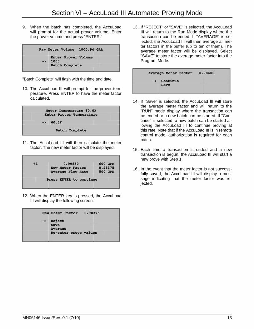
9. When the batch has completed, the AccuLoad will prompt for the actual prover volume. Enter the prover volume and press "ENTER."
Raw Meter Volume 1000.94 GAL
Enter Prover Volume -> 1000 Batch Complete
"Batch Complete" will flash with the time and date. 10. The AccuLoad III will prompt for the prover tem-
perature. Press ENTER to have the meter factor calculated.
Meter Temperature 60.0F Enter Prover Temperature
-> 60.5F
Batch Complete
11. The AccuLoad III will then calculate the meter
factor. The new meter factor will be displayed.
#1 0.99850 600 GPM New Meter Factor 0.98375
Average Flow Rate 500 GPM
Press ENTER to continue
12. When the ENTER key is pressed, the AccuLoad
III will display the following screen.
New Meter Factor 0.98375
-> Reject Save Average Re-enter prove values
13. If "REJECT" or "SAVE" is selected, the AccuLoad III will return to the Run Mode display where the transaction can be ended. If "AVERAGE" is se-lected, the AccuLoad III will then average all me-ter factors in the buffer (up to ten of them). The average meter factor will be displayed. Select "SAVE" to store the average meter factor into the Program Mode.
Average Meter Factor 0.98400
-> Continue Save
14. If "Save" is selected, the AccuLoad III will store the average meter factor and will return to the "RUN" mode display where the transaction can be ended or a new batch can be started. If "Con-tinue" is selected, a new batch can be started al-lowing the AccuLoad III to continue proving at this rate. Note that if the AccuLoad III is in remote control mode, authorization is required for each batch.
15. Each time a transaction is ended and a new transaction is begun, the AccuLoad III will start a new prove with Step 1.
16. In the event that the meter factor is not success-fully saved, the AccuLoad III will display a mes-sage indicating that the meter factor was re-jected.
Section VII – Appendix
MN06146 Issue/Rev. 0.1 (7/10) 14
Section VII – Appendix
MN06146 Issue/Rev. 0.1 (7/10) 15
0 10 20 30 40 50 60 70 80 90 100 110 120
Temperature ˚F
Tank Prover Steel Correction Factor for TemperatureAppendix BVo
lum
etri
c C
orr
ecti
on
Fac
tor
304
Stain
less
Steel
Mild S
teel
0.9980
0.9985
0.9990
0.9995
1.0000
1.0005
1.0010
1.0015

Printed in U.S.A. © 7/10 FMC Technologies Measurement Solutions, Inc. All rights reserved. MN06146 Issue/Rev. 0.1 (7/10)
Revisions included in MN06146 Issue/Rev. 0.1 (7/10): Page 1: Note added.
Visit our website at www.fmctechnologies.com/measurementsolutions
The specifications contained herein are subject to change without notice and any user of said specifications should verify from the manufacturer that the specifications are currently in effect. Otherwise, the manufacturer assumes no responsibility for the use of specifications which may have been changed and are no longer in effect.
Contact information is subject to change. For the most current contact information, visit our website at www.fmctechnologies.com/measurementsolutions and click on the “Contact Us” link in the left-hand column.
Headquarters:500 North Sam Houston Parkway West, Suite 100, Houston, TX 77067 USA, Phone: +1 (281) 260 2190, Fax: +1 (281) 260 2191
Measurement Products and Equipment: Erie, PA USA +1 (814) 898 5000Ellerbek, Germany +49 (4101) 3040Barcelona, Spain +34 (93) 201 0989Beijing, China +86 (10) 6500 2251Buenos Aires, Argentina +54 (11) 4312 4736Burnham, England +44 (1628) 603205
Dubai, United Arab Emirates +971 (4) 883 0303Los Angeles, CA USA +1 (310) 328 1236Melbourne, Australia +61 (3) 9807 2818Moscow, Russia +7 (495) 5648705Singapore, +65 6861 3011Thetford, England +44 (1842) 822900
Integrated Measurement Systems:Corpus Christi, TX USA +1 (361) 289 3400Kongsberg, Norway +47 (32) 286700San Juan, Puerto Rico +1 (787) 772 8100Dubai, United Arab Emirates +971 (4) 883 0303