Smile 41 AS-i - ABB Ltd · ABB Jokab Safety Varlabergsvägen 11, 434 39 Kungsbacka Original...
14
ABB Jokab Safety Varlabergsvägen 11, 434 39 Kungsbacka www.abb.com/jokabsafety Original instructions Smile 41AS-i Push-button box with / without safe AS-i input slaves
-
Upload
hoangkhuong -
Category
Documents
-
view
213 -
download
0
Transcript of Smile 41 AS-i - ABB Ltd · ABB Jokab Safety Varlabergsvägen 11, 434 39 Kungsbacka Original...
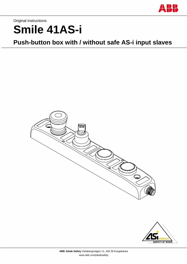
ABB Jokab Safety Varlabergsvägen 11, 434 39 Kungsbacka www.abb.com/jokabsafety
Original instructions
Smile 41AS-i Push-button box with / without safe AS-i input slaves
2TLC172255M0201, rev. B 2 www.abb.com/jokabsafety 2014-11-06
Read and understand this document Please read and understand this document before using the products. Please consult your ABB JOKAB SAFETY representative if you have any questions or comments.
WARRANTY
ABB JOKAB SAFETY’s exclusive warranty is that the products are free from defects in materials and workmanship for a period of one year (or other period if specified) from date of sale by ABB JOKAB SAFETY.
ABB JOKAB SAFETY MAKES NO WARRANTY OR REPRESENTATION, EXPRESSED OR IMPLIED, REGARDING NON-INFRINGEMENT, MERCHANTABILITY, OR FITNESS FOR PARTICULAR PURPOSE OF THE PRODUCTS, ANY BUYER OR USER ACKNOWLEDGES THAT THE BUYER OR USER ALONE HAS DETERMINED THAT THE PRODUCTS WILL SUITABLY MEET THE REQUIREMENTS OR THEIR INTENDED USE. ABB JOKAB SAFETY DISCLAIMS ALL OTHER WARRANTIES, EXPRESSED OR IMPLIED.
LIMITATIONS OF LIABILITY
ABB JOKAB SAFETY SHALL NOT BE RESPONSIBLE FOR SPECIAL, INDIRECT, OR CONSEQUENTIAL DAMAGES, LOSS OF PROFITS OR COMMERCIAL LOSS IN ANY WAY CONNECTED WITH THE PRODUCTS, WHETHER SUCH CLAIM IS BASED ON CONTRACT, WARRANTY, NEGLIGENCE, OR STRICT LIABILITY.
In no event shall responsibility of ABB JOKAB SAFETY for any act exceed the individual price of the product on which liability asserted.
IN NO EVENT SHALL ABB JOKAB SAFETY BE RESPONSIBLE FOR WARRANTY, REPAIR, OR OTHER CLAIMS REGARDING THE PRODUCTS UNLESS ABB JOKAB SAFETY’S ANALYSIS CONFIRMS THAT THE PRODUCTS WERE PROPERLY HANDLED, STORED, INSTALLED, AND MAINTAINED AND NOT SUBJECT TO ABUSE, MISUSE, OR INAPPROPRIATE MODIFICATION OR REPAIR.
SUITABILITY FOR USE
ABB JOKAB SAFETY shall not be responsible for conformity with any standards, codes, or regulations that apply to the combination of products in the customer’s application or use of the product. At the customer’s request, ABB JOKAB SAFETY will provide applicable third party certification documents identifying ratings and limitations of use that apply to the products. This information by itself is not sufficient for a complete determination of the suitability of the products in combination with the end product, machine, system, or other application or use.
The following are some examples of applications for which particular attention must be given. This is not intended to be an exhaustive list of all possible uses of the products, nor is it intended to imply that the uses listed may be suitable for the products:
Outdoor use, uses involving potential chemical contamination or electrical interference, or conditions or uses not described in this document.
Nuclear energy control systems, combustion systems, railroad systems, aviation systems, medical equipment, amusement machines, vehicles, and installations subject to separate industry or government regulations.
Systems, machines, and equipment that could present a risk to life or property.
Please know and observe all prohibitions of use applicable to the products.
NEVER USE THE PRODUCTS FOR AN APPLICATION INVOLVING SERIOUS RISK TO LIFE OR PROPERTY WITHOUT ENSURING THAT THE SYSTEM AS A WHOLE HAS BEEN DESIGNED TO ADDRESS THE RISKS, AND THAT THE ABB JOKAB SAFETY PRODUCT IS PROPERLY RATED AND INSTALLED FOR THE INTENDED USE WITHIN THE OVERALL EQUIPMENT OR SYSTEM.
PERFORMANCE DATA
While every effort has been taken to ensure the accuracy of the information contained in this manual ABB JOKAB SAFETY cannot accept responsibility for errors or omissions and reserves the right to make changes and improvements without notice. Performance data given in this document is provided as a guide for the user in determining suitability and does not constitute a warranty. It may represent the result of ABB JOKAB SAFETY’S test conditions, and the users must correlate it to actual application requirements. Actual performance is subject to the ABB JOKAB SAFETY Warranty and Limitations of Liability.
2TLC172255M0201, rev. B 3 www.abb.com/jokabsafety 2014-11-06
Table of Contents 1 Introduction ......................................................................................................................................... 4
Scope ........................................................................................................................................................................ 4
Audience ................................................................................................................................................................... 4
Prerequisites ............................................................................................................................................................. 4
Special notes ............................................................................................................................................................ 4
Safety regulations ..................................................................................................................................................... 4
2 Overview .............................................................................................................................................. 5
General description ................................................................................................................................................... 5
Function Description ................................................................................................................................................. 5
Non-safe node .......................................................................................................................................................... 6
Safe nodes ................................................................................................................................................................ 6
3 Connections ........................................................................................................................................ 7
Electrical connections ............................................................................................................................................... 7
Accessories for connection to the AS-i bus .............................................................................................................. 7
4 Installation and maintenance ............................................................................................................. 8
Installation precautions ............................................................................................................................................. 8
Assembly of coloured filters ...................................................................................................................................... 8
Maintenance ............................................................................................................................................................. 8
5 Operation ............................................................................................................................................. 9
Emergency stop ........................................................................................................................................................ 9
Key switch ................................................................................................................................................................. 9
LED indication ........................................................................................................................................................... 9
Re-addressing......................................................................................................................................................... 10
6 Model overview .................................................................................................................................. 11
Accessories ............................................................................................................................................................. 11
Dimensions ............................................................................................................................................................. 11
7 Technical data ................................................................................................................................... 12
8 EC Declaration of conformity ........................................................................................................... 14
2TLC172255M0201, rev. B 4 www.abb.com/jokabsafety 2014-11-06
1 Introduction Scope The purpose of these instructions is to describe the push-button box Smile 41 AS-i (with variants Smile 41 WWWWN AS-i, Smile 41 EWWWA AS-i and Smile 41 EKWWA AS-i), and to provide the necessary information required for installation, operation, checks and adjustment after installation and maintenance. Unless other stated, the information given applies to all variants of Smile 41 AS-i.
Audience This document is intended for authorized installation personnel.
Prerequisites It is assumed that the reader of this document has knowledge of the following:
• Basic knowledge of ABB Jokab Safety products.
• Knowledge of the AS-i system.
• Knowledge of machine safety.
Special notes Pay attention to the following special notes in the document:
Safety regulations
Warning! Carefully read through this entire manual before using the device.
The devices shall be installed by a trained electrician following the Safety regulations, standards and the Machine directive.
Failure to comply with instructions, operation that is not in accordance with the use prescribed in these instructions, improper installation or handling of the device can affect the safety of people and the plant.
For installation and prescribed use of the product, the special notes in the instructions must be carefully observed and the technical standards relevant to the application must be considered.
In case of failure to comply with the instructions or standards, especially when tampering with and/or modifying the product, any liability is excluded.
After installation or after changes in existing equipment all safety functions must be tested and verified before the equipment is used.
Warning! Danger of severe personal injury! An instruction or procedure which, if not carried out correctly, may result in injury to the technician or other personnel.
Caution! Danger of damage to the equipment! An instruction or procedure which, if not carried out correctly, may damage the equipment.
NB: Notes are used to provide important or explanatory information.
2TLC172255M0201, rev. B 5 www.abb.com/jokabsafety 2014-11-06
2 Overview General description Smile 41 AS-i is a push-button box with various possibilities to control the protection surrounding a machine, for instance to allow start, stop and reset when a protective device has been activated.
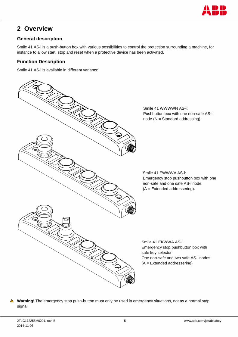
Function Description Smile 41 AS-i is available in different variants:
Warning! The emergency stop push-button must only be used in emergency situations, not as a normal stop signal.
Smile 41 EKWWA AS-i: Emergency stop pushbutton box with safe key selector One non-safe and two safe AS-i nodes. (A = Extended addressering)
Smile 41 WWWWN AS-i: Pushbutton box with one non-safe AS-i node (N = Standard addressing).
Smile 41 EWWWA AS-i: Emergency stop pushbutton box with one non-safe and one safe AS-i node. (A = Extended addressering).
2TLC172255M0201, rev. B 6 www.abb.com/jokabsafety 2014-11-06
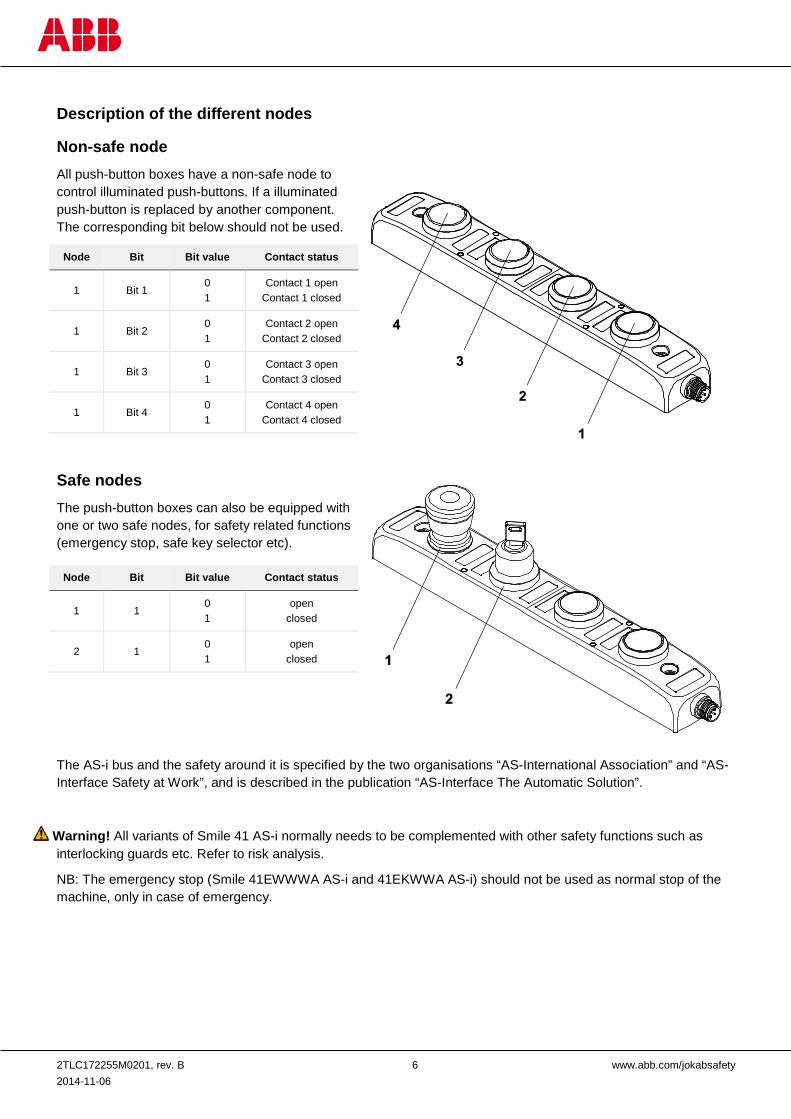
Description of the different nodes
Non-safe node All push-button boxes have a non-safe node to control illuminated push-buttons. If a illuminated push-button is replaced by another component. The corresponding bit below should not be used.
Node Bit Bit value Contact status
1 Bit 1 0 1
Contact 1 open Contact 1 closed
1 Bit 2 0 1
Contact 2 open Contact 2 closed
1 Bit 3 0 1
Contact 3 open Contact 3 closed
1 Bit 4 0 1
Contact 4 open Contact 4 closed
Safe nodes The push-button boxes can also be equipped with one or two safe nodes, for safety related functions (emergency stop, safe key selector etc).
The AS-i bus and the safety around it is specified by the two organisations “AS-International Association” and “AS-Interface Safety at Work”, and is described in the publication “AS-Interface The Automatic Solution”.
Warning! All variants of Smile 41 AS-i normally needs to be complemented with other safety functions such as interlocking guards etc. Refer to risk analysis.
NB: The emergency stop (Smile 41EWWWA AS-i and 41EKWWA AS-i) should not be used as normal stop of the machine, only in case of emergency.
Node Bit Bit value Contact status
1 1 0 1
open closed
2 1 0 1
open closed
2TLC172255M0201, rev. B 7 www.abb.com/jokabsafety 2014-11-06
3 Connections Electrical connections
Accessories for connection to the AS-i bus Type Article number Description
AS-i T-connector with M12 2TLA020073R0000 Flat cable connector to M12
M12-C112 2TLA020056R2000 1 m cable, 5-pole, 0.34 mm2, M12 female + M12 male connectors
M12-C312 2TLA020056R2100 3 m cable, 5-pole, 0.34 mm2, M12 female + M12 male connectors
M12 4-pole male connector seen from cable side.
M12 4-pole female connector seen from cable side
4-pole M12 connector:
1 ) AS-i + 2 ) Not used 3 ) AS-i – 4 ) Not used
4-pole male connector
5 x 0.34 mm2 cable, screen with straight female and male M12 connectors. Screen connected to pin 3 (0 VDC) on male connector.
Flat cable connector to M12
2TLC172255M0201, rev. B 8 www.abb.com/jokabsafety 2014-11-06
4 Installation and maintenance
Installation precautions Mount Smile 41 AS-i using two M5 bolts before attaching the M12-connector.
Warning! All the safety functions must be tested before starting up the system.
Assembly of coloured filters To illustrate the different functions of the push-buttons, coloured filters can be pressed over the original push-buttons as shown below. A kit with five filters in different colours are delivered with the unit.
Maintenance
Warning! The safety functions and the mechanics shall be tested regularly, at least once every year to confirm that all the safety functions are working properly.
Warning! In case of breakdown or damage to the product, contact the nearest ABB Jokab Safety Service Office or reseller. Do not try to repair the product yourself since it may accidentally cause permanent damage to the product, impairing the safety of the device which in turn could lead to serious injury to personnel.
Caution! ABB Jokab Safety will not accept responsibility for failure of the switch functions if the installation and maintenance requirements shown in this sheet are not implemented. These requirements form part of the product warranty.
Smile 41 AS-i is supplied with 30 VDC from the AS-i bus.
Recommended connection to the AS-i bus is through a flat cable connector to M12 (see figure to the left), making it possible to quickly and easily connect the unit to the yellow AS-i cable.
Smile 41 AS-i can also be connected directly to the AS-i bus using only two cables (pin-1 and 3 of the M12-connector on the unit).
2TLC172255M0201, rev. B 9 www.abb.com/jokabsafety 2014-11-06
5 Operation Emergency stop Push the emergency stop button. An actuating force of 22 ± 4 N is required and the actuator travel is approximately 4 mm to latch.
Pull the button until the button is unlatched.
Key switch The selector switch is safely activated when it is in the right position. The key can be taken out in both left and right position.
NOTE: The keys for the selector switch is not individual coded.
LED indication LED-indication is programmed individually in the PLC-programed according to the table below, depending on variant.
LED indication on non-safe node:
LED indication on safe nodes:
Led Indication is programmed individually per function and per safe node in the PLC-program according to the table below. The status of a push-button can be indicated by a central LED. If bit 1 and bit 2 both are set to 1 the LED will be “off”. A key selector can be indicated by one LED to the right and one to the left. The picture illustrates the position of the LEDs on a unit with both emergency stop and key selector. In this case they have on safe node each.
Node Bit Bit value LED status
1 1 0 1
LED 1 off LED 1 on
1 2 0 1
LED 2 off LED 2 on
1 3 0 1
LED 3 off LED 3 on
1 4 0 1
LED 4 off LED 4 on
bit Bit value Function
1 0 1
Central LED off Central LED on, red
2 0 1
Central LED off Central LED on, green
3 0 1
Left LED off Left LED on
4 0 1
Right LED off Right LED on
2TLC172255M0201, rev. B 10 www.abb.com/jokabsafety 2014-11-06
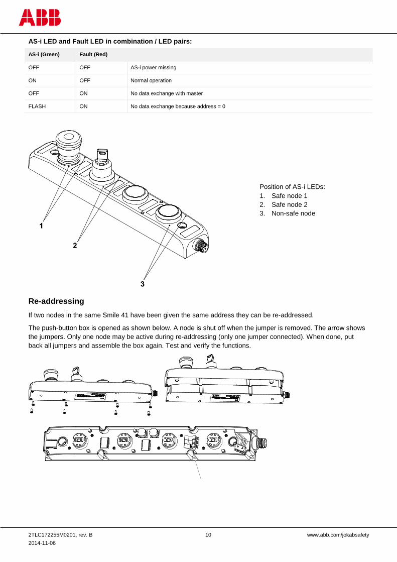
AS-i LED and Fault LED in combination / LED pairs:
AS-i (Green) Fault (Red)
OFF OFF AS-i power missing
ON OFF Normal operation
OFF ON No data exchange with master
FLASH ON No data exchange because address = 0
Re-addressing If two nodes in the same Smile 41 have been given the same address they can be re-addressed.
The push-button box is opened as shown below. A node is shut off when the jumper is removed. The arrow shows the jumpers. Only one node may be active during re-addressing (only one jumper connected). When done, put back all jumpers and assemble the box again. Test and verify the functions.
Position of AS-i LEDs: 1. Safe node 1 2. Safe node 2 3. Non-safe node
2TLC172255M0201, rev. B 11 www.abb.com/jokabsafety 2014-11-06
6 Model overview Type Article number Description
Smile 41 WWWWN AS-i 2TLA030056R0000 Push-button box
Smile 41 EWWWA AS-i 2TLA030056R0100 Push-button box with emergency stop
Smile 41 EKWWA AS-i 2TLA030056R0200 Push-button box with emergency stop and key selector
Accessories Type Article number Description
Key for key selector (spare part) 2TLA030059R1500 Key for key selector (spare part)
Kit of colour filters 2TLA030059R2600 Blue, green, red, white, yellow
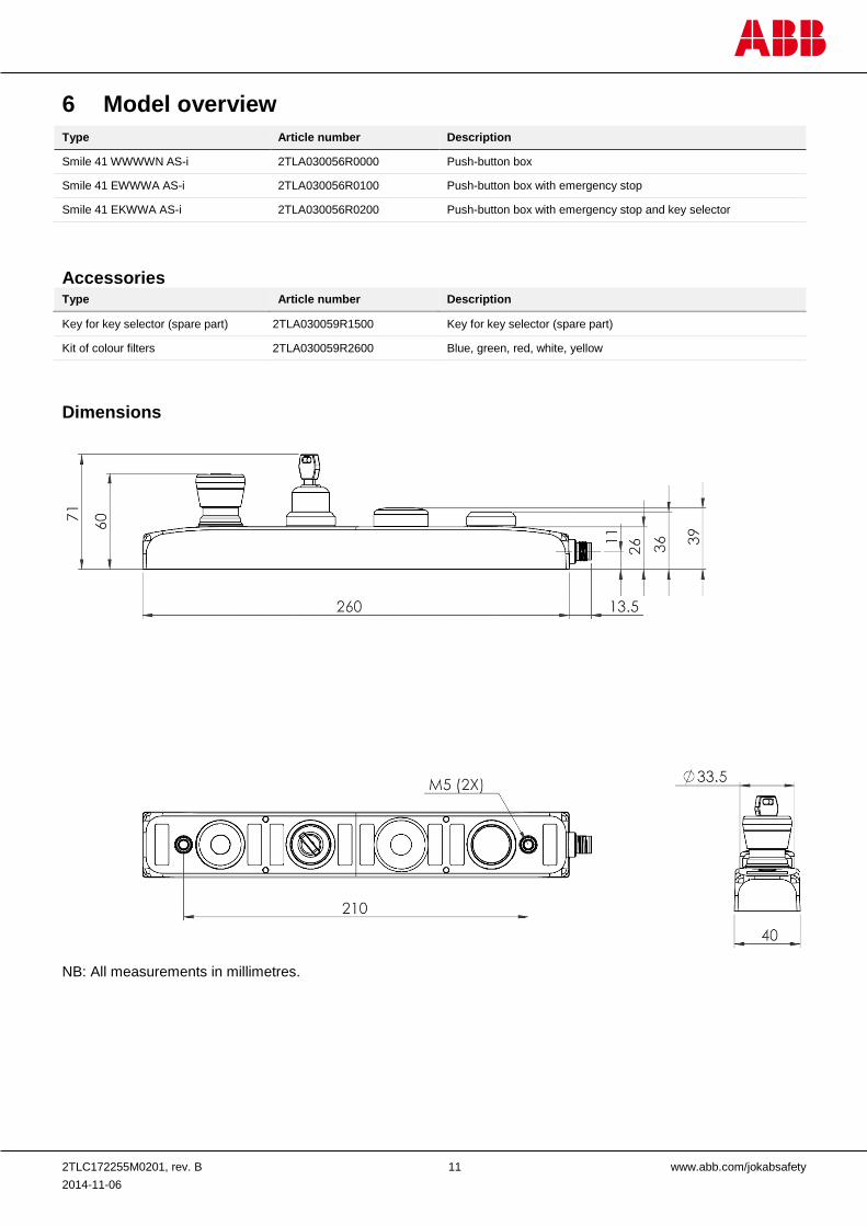
Dimensions
NB: All measurements in millimetres.
2TLC172255M0201, rev. B 12 www.abb.com/jokabsafety 2014-11-06
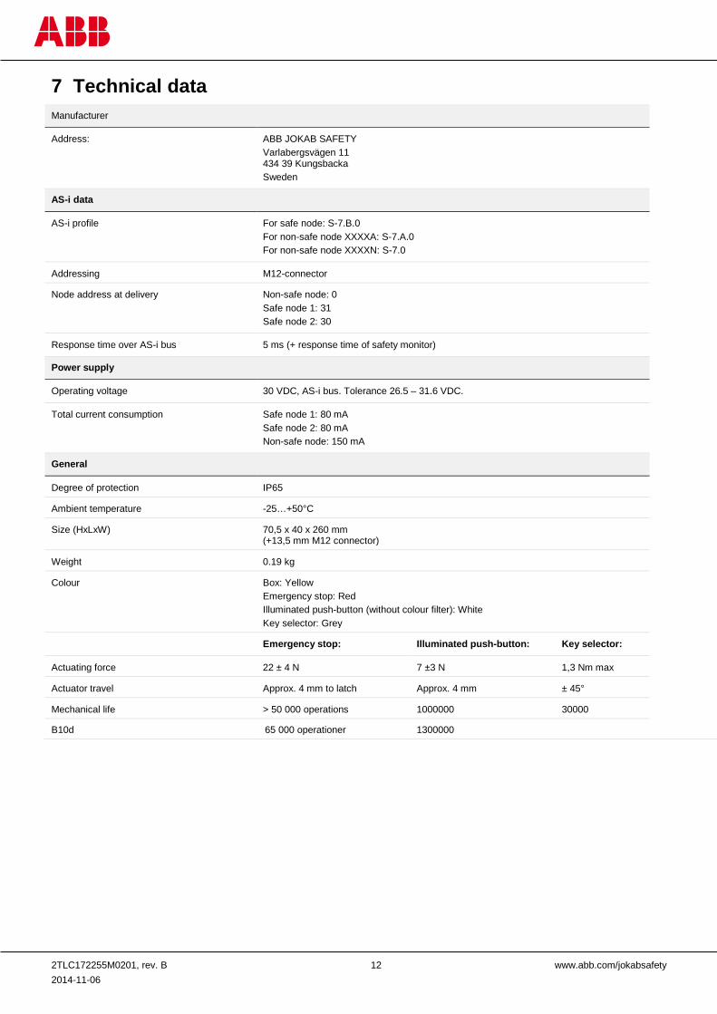
7 Technical data Manufacturer
Address: ABB JOKAB SAFETY Varlabergsvägen 11 434 39 Kungsbacka Sweden
AS-i data
AS-i profile For safe node: S-7.B.0 For non-safe node XXXXA: S-7.A.0 For non-safe node XXXXN: S-7.0
Addressing M12-connector
Node address at delivery Non-safe node: 0 Safe node 1: 31 Safe node 2: 30
Response time over AS-i bus 5 ms (+ response time of safety monitor)
Power supply
Operating voltage 30 VDC, AS-i bus. Tolerance 26.5 – 31.6 VDC.
Total current consumption Safe node 1: 80 mA Safe node 2: 80 mA Non-safe node: 150 mA
General
Degree of protection IP65
Ambient temperature -25…+50°C
Size (HxLxW) 70,5 x 40 x 260 mm (+13,5 mm M12 connector)
Weight 0.19 kg
Colour Box: Yellow Emergency stop: Red Illuminated push-button (without colour filter): White Key selector: Grey
Emergency stop: Illuminated push-button: Key selector:
Actuating force 22 ± 4 N 7 ±3 N 1,3 Nm max
Actuator travel Approx. 4 mm to latch Approx. 4 mm ± 45°
Mechanical life > 50 000 operations 1000000 30000
B10d 65 000 operationer 1300000
2TLC172255M0201, rev. B 13 www.abb.com/jokabsafety 2014-11-06
For the North American market (UL)
Enclosure Type 1
Cable assemblies Must comply with CYJV/7. Cord provided shall be 24 AWG (0.2mm2) minimum
Power source The Limited voltage source must comply with: a) The maximum open circuit voltage potential available to the circuit shall not be
more than 42.4 V peak; b) All external circuit interconnecting cable cables shall be protected against
burnout and damage to the insulation resulting from any overload or short circuit condition per the following table, based on the cable conductor size.
Conductor size Maximum ampere ratings of the overcurrent protection. AWG (mm) Ampere. 22 (0.32) 3 20 (0.52) 5 18 (0.82) 7 16 (1.3) 10 14 (2.1) 20 12 (3.3) 50
Safety / Harmonized Standards
Conformity European Machinery Directive 2006/42/EC EN ISO 12100:2010, EN ISO 13849-1:2008/AC:2009, EN ISO 13849-2:2008, EN 60204-
1:2007+A1, EN ISO 13850:2008
IEC/EN 61508-1…7 SIL3, PFDavr: 2.95*10-6, PFHd: 6.95*10-9
EN 62061 SIL3
EN ISO 13849-1 Performance level: PL e, category 4 MTTFd: High
EN 60947-5-1 & -5 For E-stop button / safety stop button
EN ISO 13850:2008 For E-stop button / safety stop button
Certification TÜV Nord (AS-i), cULus, TÜV Süd, (Emergency stop)
2TLC172255M0201, rev. B 14 www.abb.com/jokabsafety 2014-11-06
8 EC Declaration of conformity
ABB JOKAB SAFETY Varlabergsvägen 11, 434 39 Kungsbacka, Sweden
www.abb.com/jokabsafety