SmartLi nk™ Wall Station Installat ion - Full Compass · Holzkirchen, DE Ohmstrasse 3, 83607...
8
ETC Installation Guide SmartLink™ Wall Station Installation . c n I , C T E 8 f o 1 e g a P n o i t a l l a t s n I n o i t a t S l l a W ™ k n i L t r a m S Corporate Headquarters 3031 Pleasant View Road, P.O. Box 620979, Middleton, Wisconsin 53562-0979 USA Tel +608 831 4116 Fax +608 836 1736 London, UK Unit 26-28, Victoria Industrial Estate, Victoria Road, London W3 6UU, UK Tel +44 (0)20 8896 1000 Fax +44 (0)20 8896 2000 Rome, IT Via Ennio Quirino Visconti, 11, 00193 Rome, Italy Tel +39 (06) 32 111 683 Fax +44 (0)20 8896 2000 Holzkirchen, DE Ohmstrasse 3, 83607 Holzkirchen, Germany Tel +49 (80 24) 47 00-0 Fax +49 (80 24) 47 00-3 00 Hong Kong Rm 1801, 18/F, Tower 1 Phase 1, Enterprise Square, 9 Sheung Yuet Road, Kowloon Bay, Kowloon, Hong Kong Tel +852 2799 1220 Service: (Americas) [email protected] (UK) [email protected] (DE) [email protected] (Asia) [email protected] Web: www.etcconnect.com Copyright © 2009 ETC. All Rights Reserved. Product information and specifications subject to change. 7124M2210 Rev B Released 2009-06 ETC intends this document to be provided in its entirety. Overview SmartLink button preset stations provide remote access to the 32 built-in presets and sequencer found in SmartLink™ enabled SmartPack and SmartSwitch products. When used with the and Unison DRd host or CEM+, SmartLink provides remote access to the first 64 built in presets. Station electronics mount directly into a flush mount, single gang, industry standard back box. Station faceplates and buttons are constructed of ABS plastic and are available in white, ivory, grey, black and signal white. Station legends are laser marked in a contrasting color. SmartLink stations are provided with station electronics, buttons, faceplate, a LinkConnect termination kit, wire termination hardware and installation hardware. Installation Requirements SmartLink requires (1) Belden 8471 and (1) 2.50mm 2 (14 AWG) ESD ground wire. A SmartLink data run is limited to 1500 feet and is topology-free and polarity independent. Wiring may be bus, star, loop, home run or any combination of these. Reference the associated SmartLink host product Installation Manual for instructions to terminate station wiring at the host product. Note: ETC requires that all stations be grounded by using grounded metal conduit or a 14 AWG ESD drain wire. All control wiring should be installed and terminated by a qualified installer and should follow standard wiring installation practices. Note: You may have only one station power source on the SmartLink network. This source may be either the LinkPower Supply (S-LPS) which powers up to four stations or a SmartLink Station Power Module (S-SPM) which powers up to 16 stations. The presence of multiple power supplies on a SmartLink network will cause unpredictable results and is likely to damage electronics. As well, you may have up to four SmartLink host products in a SmartLink system. One SmartLink host product (SmartPack, SmartSwitch, Unison DRd with SmartLink or Sensor + with SmartLink) in the system must have a LinkPower Supply or Station Power Module installed for wall station power. SmartLink station use with the SmartPack Portable dimmer pack requires an external LinkPower supply. Contact ETC for assistance.
Transcript of SmartLi nk™ Wall Station Installat ion - Full Compass · Holzkirchen, DE Ohmstrasse 3, 83607...

E T C I n s t a l l a t i o n G u i d eSmartLink™ Wall Station Installation
S
CoLoRoHoHoSeW71
Overv iewSmartLink button preset stations provide remote access to the 32 built-in presets and sequencer found in SmartLink™ enabled SmartPack and SmartSwitch products. When used with the and Unison DRd host or CEM+, SmartLink provides remote access to the first 64 built in presets.Station electronics mount directly into a flush mount, single gang, industry standard back box. Station faceplates and buttons are constructed of ABS plastic and are available in white, ivory, grey, black and signal white. Station legends are laser marked in a contrasting color.SmartLink stations are provided with station electronics, buttons, faceplate, a LinkConnect termination kit, wire termination hardware and installation hardware.
Ins ta l la t ion Requ i rementsSmartLink requires (1) Belden 8471 and (1) 2.50mm2 (14 AWG) ESD ground wire. A SmartLink data run is limited to 1500 feet and is topology-free and polarity independent. Wiring may be bus, star, loop, home run or any combination of these.
Reference the associated SmartLink host product Installation Manual for instructions to terminate station wiring at the host product.
N o t e : ETC requires that all stations be grounded by using grounded metal conduit or a 14 AWG ESD drain wire. All control wiring should be installed and terminated by a qualified installer and should follow standard wiring installation practices.
N o t e : You may have only one station power source on the SmartLink network. This source may be either the LinkPower Supply(S-LPS) which powers up to four stations or a SmartLink Station Power Module (S-SPM) which powers up to 16 stations. The presence of multiple power supplies on a SmartLink network will cause unpredictable results and is likely to damage electronics.As well, you may have up to four SmartLink host products in a SmartLink system. One SmartLink host product (SmartPack, SmartSwitch, Unison DRd with SmartLink or Sensor + with SmartLink) in the system must have a LinkPower Supply or Station Power Module installed for wall station power. SmartLink station use with the SmartPack Portable dimmer pack requires an external LinkPower supply. Contact ETC for assistance.
.cnI ,CTE8 fo 1 egaP noitallatsnI noitatS llaW ™kniLtram
rporate Headquarters 3031 Pleasant View Road, P.O. Box 620979, Middleton, Wisconsin 53562-0979 USA Tel +608 831 4116 Fax +608 836 1736ndon, UK Unit 26-28, Victoria Industrial Estate, Victoria Road, London W3 6UU, UK Tel +44 (0)20 8896 1000 Fax +44 (0)20 8896 2000me, IT Via Ennio Quirino Visconti, 11, 00193 Rome, Italy Tel +39 (06) 32 111 683 Fax +44 (0)20 8896 2000lzkirchen, DE Ohmstrasse 3, 83607 Holzkirchen, Germany Tel +49 (80 24) 47 00-0 Fax +49 (80 24) 47 00-3 00ng Kong Rm 1801, 18/F, Tower 1 Phase 1, Enterprise Square, 9 Sheung Yuet Road, Kowloon Bay, Kowloon, Hong Kong Tel +852 2799 1220rvice: (Americas) [email protected] (UK) [email protected] (DE) [email protected] (Asia) [email protected]
eb: www.etcconnect.com Copyright © 2009 ETC. All Rights Reserved. Product information and specifications subject to change.24M2210 Rev B Released 2009-06 ETC intends this document to be provided in its entirety.
E T C I n s t a l l a t i o n G u i d eSmartLink™ Wall Station Installation
S
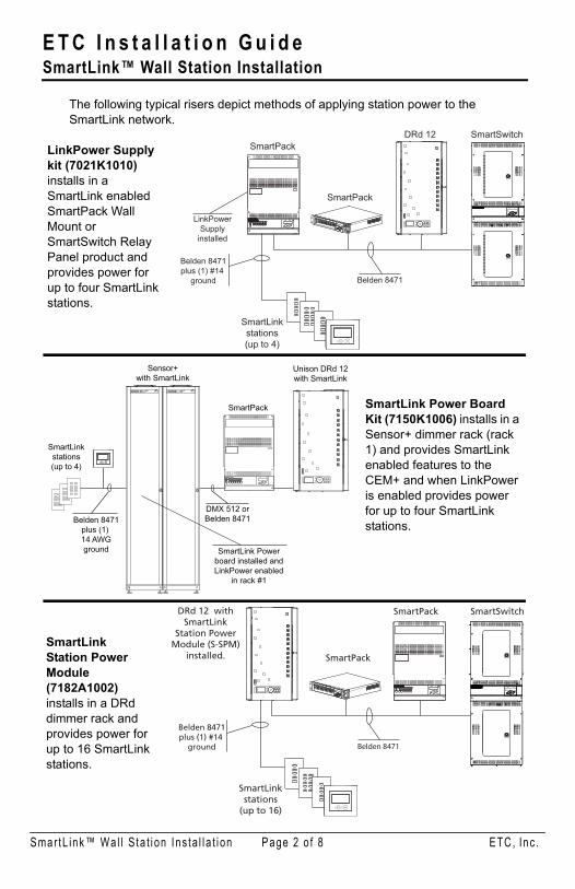
The following typical risers depict methods of applying station power to the SmartLink network.
Preset 5
Preset 1
Preset 2
Preset 4
Preset 3
Preset 10
Preset 6
Preset 7
Preset 9
Preset 8
Preset 5
Preset 1
Preset 2
Preset 4
Preset 3
Preset 5
Preset 1
Preset 2
Preset 4
Preset 3
BackUp
Enter
RecallPreset
HoldDown
Belden 8471plus (1) #14
ground
SmartLinkstations
(up to 16)
Belden 8471
SmartPack
SmartPack
DRd 12 withSmartLink
Station PowerModule (S-SPM)
installed.
SmartSwitch
DMX
Preset 5
Preset 1
Preset 2
Preset 4
Preset 3
Preset 10
Preset 6
Preset 7
Preset 9
Preset 8
Preset 5
Preset 1
Preset 2
Preset 4
Preset 3
Preset 5
Preset 1
Preset 2
Preset 4
Preset 3
BackUp
Enter
RecallPreset
HoldDown
Belden 8471plus (1) #14
ground
SmartLinkstations(up to 4)
Belden 8471
SmartPack
SmartPack
DRd 12 SmartSwitch
LinkPowerSupply
installed
DMX
LinkPower Supply kit (7021K1010) installs in a SmartLink enabled SmartPack Wall Mount or SmartSwitch Relay Panel product and provides power for up to four SmartLink stations.
SmartLink Power Board Kit (7150K1006) installs in a Sensor+ dimmer rack (rack 1) and provides SmartLink enabled features to the CEM+ and when LinkPower is enabled provides power for up to four SmartLink stations.
Sensor+with SmartLink
Belden 8471plus (1) 14 AWGground
DMX 512 orBelden 8471
SmartLink Powerboard installed andLinkPower enabled
in rack #1
SmartPack
Unison DRd 12with SmartLink
D I M M I N G S Y S T E M D I M M I N G S Y S T E M
BackUp
Enter
RecallPreset
HoldDown
Preset 1
Preset 2
Preset 3
Preset 4
Preset 5
Preset 6
Preset 7
Preset 8
Preset 9
Preset 10
Preset 1
Preset 2
Preset 3
Preset 4
Preset 5
Preset 6
Preset 7
Preset 8
Preset 9
Preset 10
Preset 1
Preset 2
Preset 3
Preset 4
Preset 5
Preset 6
Preset 7
Preset 8
Preset 9
Preset 10
SmartLinkstations(up to 4)
SmartLinkStation Power Module (7182A1002) installs in a DRd dimmer rack and provides power for up to 16 SmartLinkstations.
mar tL ink™ Wa l l S ta t i on I ns ta l l a t i on Page 2 o f 8 ETC, Inc .

E T C I n s t a l l a t i o n G u i d eSmartLink™ Wall Station Installation
S
Ins ta l l ing the Smar tL ink But ton S ta t ionThe following instructions assume the backbox is installed and the station wiring is roughed-in using Belden 8471. If substitute wire is used, contact ETC to ensure compatibility.
The backbox should be installed square for best results. Ensure that the backbox is clean and free of obstructions and that all wiring is installed correctly. Leave approximately 10 inches (254mm) of wiring in the backbox for connection and to allow slack for future service needs.
SmartLink button stations ship with a LinkConnect termination kit containing a
LinkPower pigtail, a ground wire pigtail, spacers, and all required connectors for installation.
Connect ing the Wir ingStep 1: Pull all required wiring to the backbox.Step 2: Terminate and connect LinkPower. LinkPower is topology free and
polarity independent. You may install LinkPower in any combination of bus, loop, star or home-run.
a: Locate the LinkPower pigtail and two WAGO CAGE CLAMP® connectors from the termination kit.
b: Strip 3/8” (9-10mm) from the ends of each LinkPower wire (both pigtail and installed LinkPower wire).
c: Use the WAGO CAGE CLAMP connector to connect the installed control wire to the connectorized pigtail wires provided. Open the terminal levers on the WAGO connector and insert the installed (typically black) Belden 8471 LinkPower wire and the black lead from the LinkPower pigtail into the terminals.
d: Close the levers onto the wires.
LinkPower pigtail
Groundpigtail
WAGO
Spacers
Topology of a single station installation
Topology of multiple stations installed in series
Installed control wire
Pigtail wire
Installed control wireInstalled wire to next stationPigtail wire
mar tL ink™ Wa l l S ta t i on I ns ta l l a t i on Page 3 o f 8 ETC, Inc .

E T C I n s t a l l a t i o n G u i d eSmartLink™ Wall Station Installation
S
e: Repeat for the installed (typically white) Belden 8471 LinkPower wire and remaining pigtail wire using a new WAGO connector.
f: Install the LinkPower connector onto the SmartLink Button Station control board.
Step 3: Terminate the ESD drain (ground) wire. This connection is required only when the control cable is not installed in grounded metal conduit.a: Locate the ground wire pigtail
and one WAGO CAGE CLAMP connector from the termination kit.
b: Strip 3/8” (9-10mm) from the end of each ground wire (both the provided pigtail and the installed wire).
c: Use the WAGO CAGE CLAMP connector to connect the installed ground wire to the pigtail wire provided. Open the terminal levers on the WAGO connector and insert the installed (typically green/yellow) ESD drain (ground) wire and the green/yellow lead from the pigtail into the terminals.
d: Close the levers onto the wires.e: Install the ground spade onto the receptacle on the SmartLink
Button Station control board.
Sta t ion Persona l i ty Se t t ingsThe control electronics, back side of station, include a set of eight dip switches. Each setting activates standard functionality or built-in personalities including the starting preset number and sequence activation for the station.
N o t e : A ground connection (14 AWG) is required for all SmartLink Button Station assemblies if not installed in ground metal backbox.
Ground spade
LinkPower connector
12345678
OFF
12345678
OFF
12345678
OFF
mar tL ink™ Wa l l S ta t i on I ns ta l l a t i on Page 4 o f 8 ETC, Inc .
E T C I n s t a l l a t i o n G u i d eSmartLink™ Wall Station Installation
S
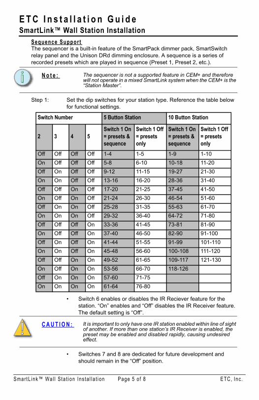
Sequence Suppor tThe sequencer is a built-in feature of the SmartPack dimmer pack, SmartSwitch relay panel and the Unison DRd dimming enclosure. A sequence is a series of recorded presets which are played in sequence (Preset 1, Preset 2, etc.).
Step 1: Set the dip switches for your station type. Reference the table below for functional settings.
• Switch 6 enables or disables the IR Reciever feature for the station. “On” enables and “Off” disables the IR Receiver feature. The default setting is “Off”.
• Switches 7 and 8 are dedicated for future development and should remain in the “Off” position.
N o t e : The sequencer is not a supported feature in CEM+ and therefore will not operate in a mixed SmartLink system when the CEM+ is the “Station Master”.
Switch Number 5 Button Station 10 Button Station
2 3 4 5Switch 1 On = presets & sequence
Switch 1 Off = presetsonly
Switch 1 On = presets & sequence
Switch 1 Off = presets only
Off Off Off Off 1-4 1-5 1-9 1-10On Off Off Off 5-8 6-10 10-18 11-20Off On Off Off 9-12 11-15 19-27 21-30On On Off Off 13-16 16-20 28-36 31-40Off Off On Off 17-20 21-25 37-45 41-50On Off On Off 21-24 26-30 46-54 51-60Off On On Off 25-28 31-35 55-63 61-70On On On Off 29-32 36-40 64-72 71-80Off Off Off On 33-36 41-45 73-81 81-90On Off Off On 37-40 46-50 82-90 91-100Off On Off On 41-44 51-55 91-99 101-110On On Off On 45-48 56-60 100-108 111-120Off Off On On 49-52 61-65 109-117 121-130On Off On On 53-56 66-70 118-126Off On On On 57-60 71-75On On On On 61-64 76-80
C A U T I O N : It is important to only have one IR station enabled within line of sight of another. If more than one station’s IR Receiver is enabled, the preset may be enabled and disabled rapidly, causing undesired effect.
mar tL ink™ Wa l l S ta t i on I ns ta l l a t i on Page 5 o f 8 ETC, Inc .

E T C I n s t a l l a t i o n G u i d eSmartLink™ Wall Station Installation
S
Change LED Co lo rThe SmartLink station supports one color for the “On” state of the LED indicator. This color can be changed to any one of 15 standard available colors.Step 1: Press and hold the service pin button approximately 10 seconds until
all LEDs light.Step 2: Press any button repeatedly to cycle through the available colors and
stop when the desired color is represented.Step 3: Press and hold the service pin button approximately 10 seconds until
the station turns off all LEDs and returns to its normal operating mode.
Ins ta l l ing the S ta t ion in to the BackboxSpacers are provided to help align the station and cover flush against the wall in flush mount applications. The spacers are not needed on surface mount backboxes.Step 1: Insert the station electronics and wiring into the backbox. The arrow
on the mounting plate must point up.
Step 2: If needed, fold the receptacle spacer in a zigzag fashion and press together to achieve the required thickness to fill the gap between the station and backbox. Cut off the excess and place between the station and flush backbox.
Step 3: Secure the station with two screws. If using spacers, insert the screws through them.
Step 4: Install the button caps so that the clear light tunnels protrude through the caps.
N o t e : For some flush mount applications with certain trim rings it may be necessary to remove the station’s back cover for installation into the backbox.
C A U T I O N : To improve successful station and wall plate installation, do not over tighten the screws. If screws are over tightened, activation can be negatively impacted.
1
32
4
mar tL ink™ Wa l l S ta t i on I ns ta l l a t i on Page 6 o f 8 ETC, Inc .

E T C I n s t a l l a t i o n G u i d eSmartLink™ Wall Station Installation
S
Ins ta l l ing the Facep la teThe faceplate is secured to the station with two magnets that are located on the bottom side of the faceplate.Step 1: Align the top of the faceplate approximately 20 degrees from the
station.
Step 2: Hook the top of the faceplate to the tabs located on the station electronics assembly. To ensure the faceplate is hooked properly on the top hook, wiggle it slightly side to side while the bottom is angled about 20 degrees from the wall.
Step 3: Swing the bottom of the faceplate down until the magnets engage.Step 4: If the faceplate does not fully attach automatically, wiggle the bottom of
the plate until the magnets are seated properly to the station and the faceplate is secure.
mar tL ink™ Wa l l S ta t i on I ns ta l l a t i on Page 7 o f 8 ETC, Inc .

E T C I n s t a l l a t i o n G u i d eSmartLink™ Wall Station Installation
S
Troub leshoot ingIf the SmartLink control station(s) will not operate after complete system installation and programming, check for shorts and cross-connections with a digital voltmeter at the station LinkPower pigtail connection and the station ground connection.
• Check the voltage between pin 1 and ground. This reading should be between 18 to 21 Volts.
• Check the voltage between pin 2 and ground. This reading should be between -18 to -21 Volts.
• Check the voltage between pin 1 and pin 2. This reading should be between 36 to 42 Volts.
Serv iceIf you have any difficulties installing your system or with system startup please contact ETC Technical Services at the office nearest you. ETC contact information is located in the boiler plate found on page 1 of this document.
ground
LinkPower
mar tL ink™ Wa l l S ta t i on I ns ta l l a t i on Page 8 o f 8 ETC, Inc .