ETC Installation Guide - Full Compass · ETC Installation Guide ... 83607 Holzkirchen, Germany ......
8
ETC Installation Guide Desire ® Series D22 Desire D22 Page 1 of 8 Electronic Theatre Controls, Inc. Corporate Headquarters 3031 Pleasant View Road, P.O. Box 620979, Middleton, Wisconsin 53562-0979 USA Tel +608 831 4116 Fax +608 836 1736 London, UK Unit 26-28, Victoria Industrial Estate, Victoria Road, London W3 6UU, UK Tel +44 (0)20 8896 1000 Fax +44 (0)20 8896 2000 Rome, IT Via Pieve Torina, 48, 00156 Rome, Italy Tel +39 (06) 32 111 683 Fax +44 (0)20 8752 8486 Holzkirchen, DE Ohmstrasse 3, 83607 Holzkirchen, Germany Tel +49 (80 24) 47 00-0 Fax +49 (80 24) 47 00-3 00 Hong Kong Rm 1801, 18/F, Tower 1 Phase 1, Enterprise Square, 9 Sheung Yuet Road, Kowloon Bay, Kowloon, Hong Kong Tel +852 2799 1220 Service: (Americas) [email protected] (UK) [email protected] (DE) [email protected] (Asia) [email protected] Web: www.etcconnect.com Copyright © 2013 ETC. All Rights Reserved. Product information and specifications subject to change. 7411M2100 Rev C Released 2013-11 ETC intends this document to be provided in its entirety. Introduction ETC’s Desire D22 is designed for indoor installations and has a rugged die-cast enclosure, steel mounting yoke, and noise-free, fan-less operation. The D22 can be pipe mounted with a C-clamp, canopy mounted, or track mounted. Mounting accessories are available. Contact ETC Customer Service for assistance; contact information is located at the bottom of this page. For information about the operation of the D22 Desire Series, refer to Desire Series by ETC D22, D40, D40XT, D60 User Manual. ETC manuals are available for download at http://www.etcconnect.com/downloads.aspx . Specifications Environment Operates in ambient temperatures of 0°C to +40°C (32°F to 104°F). CAUTION: Do not attempt to install or use a fixture until you read and understand the installation instructions and safety labels. WARNING: This fixture must be installed by a qualified electrician in accordance with all national and local electrical and construction codes and regulations. CAUTION: Risk of eye injury. Do not stare directly into the light. Do not operate in proximity to flammable materials. Portable Canopy Mount Track Mount
-
Upload
truongnhan -
Category
Documents
-
view
223 -
download
0
Transcript of ETC Installation Guide - Full Compass · ETC Installation Guide ... 83607 Holzkirchen, Germany ......

E T C I n s t a l l a t i o n G u i d e®
Desire Series D22In t roduct ionETC’s Desire D22 is designed for indoor installations and has a rugged die-cast enclosure, steel mounting yoke, and noise-free, fan-less operation.
The D22 can be pipe mounted with a C-clamp, canopy mounted, or track mounted. Mounting accessories are available. Contact ETC Customer Service for assistance; contact information is located at the bottom of this page.
For information about the operation of the D22 Desire Series, refer to Desire Series by ETC D22, D40, D40XT, D60 User Manual. ETC manuals are available for download at http://www.etcconnect.com/downloads.aspx.
Spec i f ica t ionsEnv i ronment
Operates in ambient temperatures of 0°C to +40°C (32°F to 104°F).
C A U T I O N : Do not attempt to install or use a fixture until you read and understand the installation instructions and safety labels.
W A R N I N G : This fixture must be installed by a qualified electrician in accordance with all national and local electrical and construction codes and regulations.
C A U T I O N : Risk of eye injury. Do not stare directly into the light.Do not operate in proximity to flammable materials.
Portable Canopy Mount Track Mount
Des i re D22 Page 1 o f 8 E lec t ron ic Thea t re Con t ro l s , I nc .
Corporate Headquarters 3031 Pleasant View Road, P.O. Box 620979, Middleton, Wisconsin 53562-0979 USA Tel +608 831 4116 Fax +608 836 1736London, UK Unit 26-28, Victoria Industrial Estate, Victoria Road, London W3 6UU, UK Tel +44 (0)20 8896 1000 Fax +44 (0)20 8896 2000Rome, IT Via Pieve Torina, 48, 00156 Rome, Italy Tel +39 (06) 32 111 683 Fax +44 (0)20 8752 8486Holzkirchen, DE Ohmstrasse 3, 83607 Holzkirchen, Germany Tel +49 (80 24) 47 00-0 Fax +49 (80 24) 47 00-3 00Hong Kong Rm 1801, 18/F, Tower 1 Phase 1, Enterprise Square, 9 Sheung Yuet Road, Kowloon Bay, Kowloon, Hong Kong Tel +852 2799 1220Service: (Americas) [email protected] (UK) [email protected] (DE) [email protected] (Asia) [email protected]: www.etcconnect.com Copyright © 2013 ETC. All Rights Reserved. Product information and specifications subject to change.7411M2100 Rev C Released 2013-11 ETC intends this document to be provided in its entirety.
Cont ro l
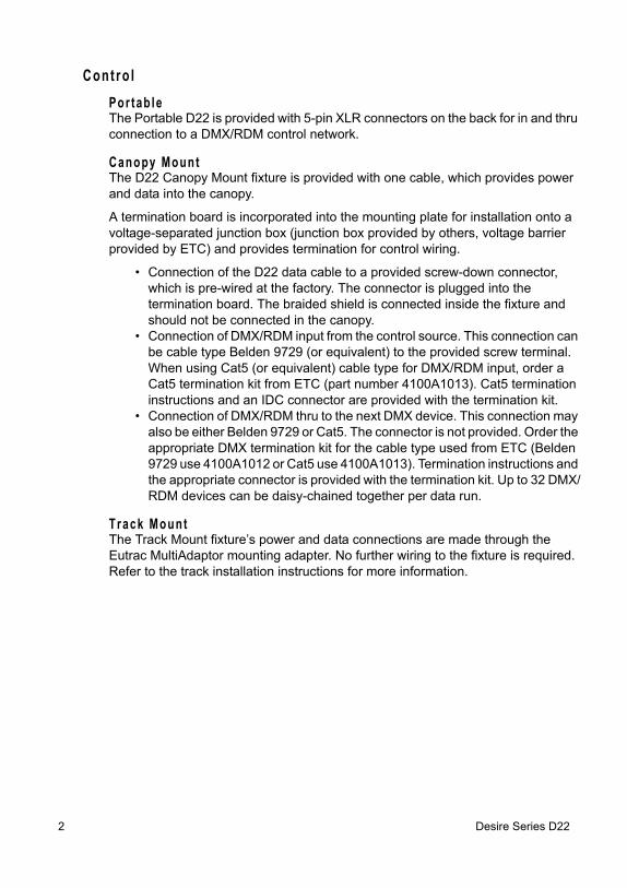
Por tab leThe Portable D22 is provided with 5-pin XLR connectors on the back for in and thru connection to a DMX/RDM control network.
Canopy MountThe D22 Canopy Mount fixture is provided with one cable, which provides power and data into the canopy.
A termination board is incorporated into the mounting plate for installation onto a voltage-separated junction box (junction box provided by others, voltage barrier provided by ETC) and provides termination for control wiring.
• Connection of the D22 data cable to a provided screw-down connector, which is pre-wired at the factory. The connector is plugged into the termination board. The braided shield is connected inside the fixture and should not be connected in the canopy.
• Connection of DMX/RDM input from the control source. This connection can be cable type Belden 9729 (or equivalent) to the provided screw terminal. When using Cat5 (or equivalent) cable type for DMX/RDM input, order a Cat5 termination kit from ETC (part number 4100A1013). Cat5 termination instructions and an IDC connector are provided with the termination kit.
• Connection of DMX/RDM thru to the next DMX device. This connection may also be either Belden 9729 or Cat5. The connector is not provided. Order the appropriate DMX termination kit for the cable type used from ETC (Belden 9729 use 4100A1012 or Cat5 use 4100A1013). Termination instructions and the appropriate connector is provided with the termination kit. Up to 32 DMX/RDM devices can be daisy-chained together per data run.
Track MountThe Track Mount fixture’s power and data connections are made through the Eutrac MultiAdaptor mounting adapter. No further wiring to the fixture is required. Refer to the track installation instructions for more information.
2 Desire Series D22
Elec t r ica l
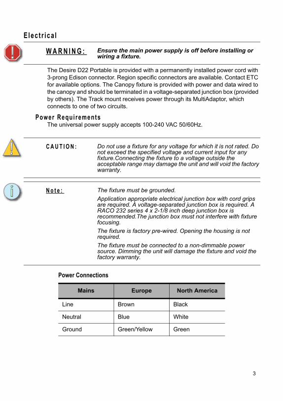
The Desire D22 Portable is provided with a permanently installed power cord with 3-prong Edison connector. Region specific connectors are available. Contact ETC for available options. The Canopy fixture is provided with power and data wired to the canopy and should be terminated in a voltage-separated junction box (provided by others). The Track mount receives power through its MultiAdaptor, which connects to one of two circuits.
Power Requi rementsThe universal power supply accepts 100-240 VAC 50/60Hz.
W A R N I N G : Ensure the main power supply is off before installing or wiring a fixture.
C A U T I O N : Do not use a fixture for any voltage for which it is not rated. Do not exceed the specified voltage and current input for any fixture.Connecting the fixture to a voltage outside the acceptable range may damage the unit and will void the factory warranty.
N o t e : The fixture must be grounded.
Application appropriate electrical junction box with cord grips are required. A voltage-separated junction box is required. A RACO 232 series 4 x 2-1/8 inch deep junction box is recommended.The junction box must not interfere with fixture focusing.
The fixture is factory pre-wired. Opening the housing is not required.
The fixture must be connected to a non-dimmable power source. Dimming the unit will damage the fixture and void the factory warranty.
Power Connections
Mains Europe North America
Line Brown Black
Neutral Blue White
Ground Green/Yellow Green
3
Ins ta l la t ionTerminat ion
The D22 Desire Series requires termination at the last fixture on a DMX/RDM line with a 120 ohm resistor.
• The Portable fixture is self terminated.• The Track fixture is terminated with a DataTrack DMX Term Block, ETC Part
# 7066A1030.• The Canopy fixture is terminated on the Termination board inside the
canopy.
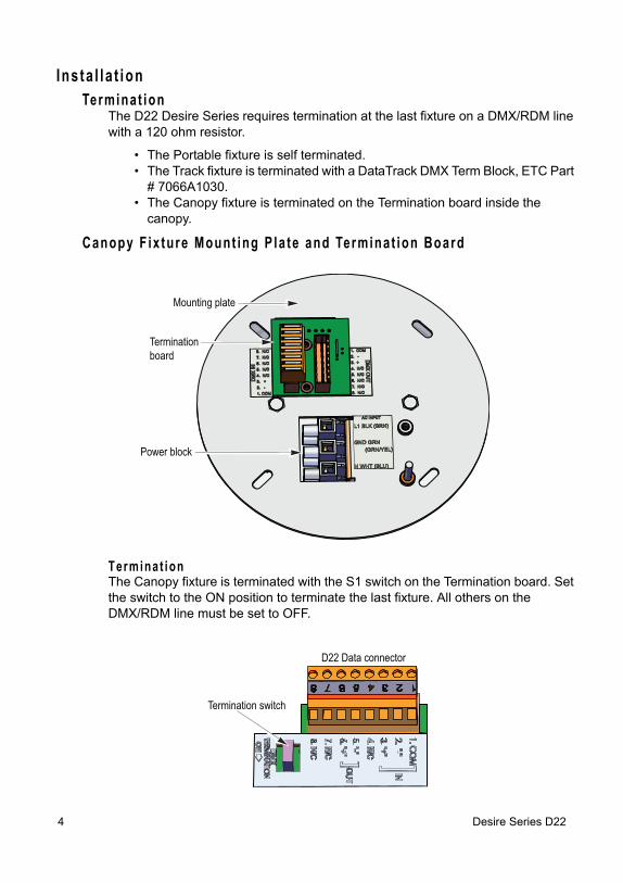
Canopy F ix ture Mount ing P la te and Terminat ion Board
Termina t ionThe Canopy fixture is terminated with the S1 switch on the Termination board. Set the switch to the ON position to terminate the last fixture. All others on the DMX/RDM line must be set to OFF.
Terminationboard
Power block
Mounting plate
Termination switch
D22 Data connector
4 Desire Series D22
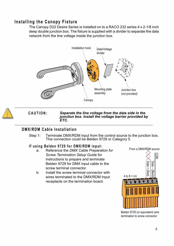
Ins ta l l ing the Canopy F ix tureThe Canopy D22 Desire Series is installed on to a RACO 232 series 4 x 2-1/8 inch deep double junction box. The fixture is supplied with a divider to separate the data network from the line voltage inside the junction box.
DMX/RDM Cable Ins ta l la t ionStep 1: Terminate DMX/RDM input from the control source to the junction box.
This connection could be Belden 9729 or Category 5.
I f us ing Be lden 9729 fo r DMX/RDM input :a: Reference the DMX Cable Preparation for
Screw Termination Setup Guide for instructions to prepare and terminate Belden 9729 for DMX input cable to the screw terminal connector.
b: Install the screw terminal connector with wires terminated to the DMX/RDM Input receptacle on the termination board.
C A U T I O N : Separate the line voltage from the data side in the junction box. Install the voltage barrier provided by ETC.
Canopy
Installation hook
Junction box(not provided)
Data/Voltagedivider
Mounting plateassembly
From a DMX/RDM source
Data – (Black)Data + (Red)
Belden 9729 (or equivalent) wiretermination to screw connector
4 to 8 = n/c
COM
5
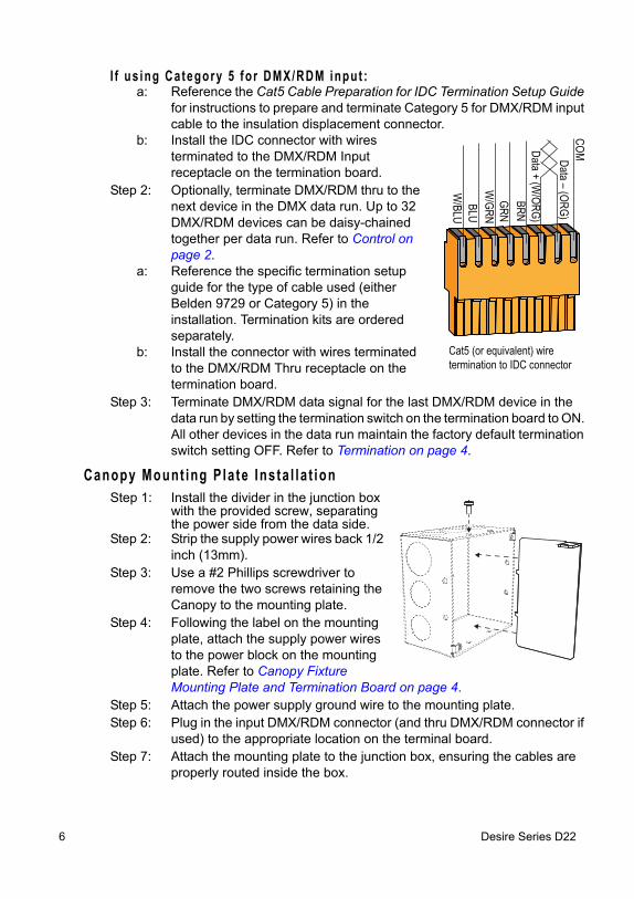
I f us ing Category 5 for DMX/RDM input :a: Reference the Cat5 Cable Preparation for IDC Termination Setup Guide
for instructions to prepare and terminate Category 5 for DMX/RDM input cable to the insulation displacement connector.
b: Install the IDC connector with wires terminated to the DMX/RDM Input receptacle on the termination board.
Step 2: Optionally, terminate DMX/RDM thru to the next device in the DMX data run. Up to 32 DMX/RDM devices can be daisy-chained together per data run. Refer to Control on page 2.
a: Reference the specific termination setup guide for the type of cable used (either Belden 9729 or Category 5) in the installation. Termination kits are ordered separately.
b: Install the connector with wires terminated to the DMX/RDM Thru receptacle on the termination board.
Step 3: Terminate DMX/RDM data signal for the last DMX/RDM device in the data run by setting the termination switch on the termination board to ON. All other devices in the data run maintain the factory default termination switch setting OFF. Refer to Termination on page 4.
Canopy Mount ing P la te Ins ta l la t ionStep 1: Install the divider in the junction box
with the provided screw, separating the power side from the data side.
Step 2: Strip the supply power wires back 1/2 inch (13mm).
Step 3: Use a #2 Phillips screwdriver to remove the two screws retaining the Canopy to the mounting plate.
Step 4: Following the label on the mounting plate, attach the supply power wires to the power block on the mounting plate. Refer to Canopy Fixture Mounting Plate and Termination Board on page 4.
Step 5: Attach the power supply ground wire to the mounting plate.Step 6: Plug in the input DMX/RDM connector (and thru DMX/RDM connector if
used) to the appropriate location on the terminal board.Step 7: Attach the mounting plate to the junction box, ensuring the cables are
properly routed inside the box.
Data – (ORG)
Data + (W/ORG)
Cat5 (or equivalent) wiretermination to IDC connector
COM
BRNGRN
W/GRNBLU
W/BLU
6 Desire Series D22
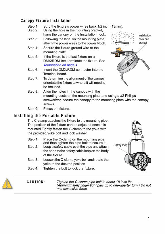
Canopy F ix ture Ins ta l la t ionStep 1: Strip the fixture’s power wires back 1/2 inch (13mm).Step 2: Using the hole in the mounting bracket,
hang the canopy on the Installation hook.Step 3: Following the label on the mounting plate,
attach the power wires to the power block.Step 4: Secure the fixture ground wire to the
mounting plate.Step 5: If the fixture is the last fixture on a
DMX/RDM line, terminate the fixture. See Termination on page 4.
Step 6: Insert the DMX/RDM connector into the Terminal board.
Step 7: To determine the alignment of the canopy, orientate the fixture to where it will need to be focused.
Step 8: Align the holes in the canopy with the mounting posts on the mounting plate and using a #2 Phillips screwdriver, secure the canopy to the mounting plate with the canopy screws.
Step 9: Focus the fixture.
Ins ta l l ing the Por tab le F ix tureThe C-clamp attaches the fixture to the mounting pipe. The position of the fixture can be adjusted once it is mounted.Tightly fasten the C-clamp to the yoke with the provided yoke bolt and lock washer.
Step 1: Place the C-clamp on the mounting pipe, and then tighten the pipe bolt to secure it.
Step 2: Loop a safety cable over the pipe and attach the ends to the safety cable loop on the body of the fixture.
Step 3: Loosen the C-clamp yoke bolt and rotate the yoke to the desired position.
Step 4: Tighten the bolt to lock the fixture.
C A U T I O N : Tighten the C-clamp pipe bolt to about 18 inch lbs. (Approximately finger tight plus up to one-quarter turn.) Do not use excessive force.
Installationhook and bracket
Safety loop
7
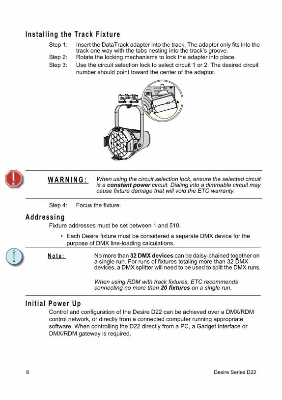
Ins ta l l ing the Track F ix tureStep 1: Insert the DataTrack adapter into the track. The adapter only fits into the
track one way with the tabs nesting into the track’s groove.Step 2: Rotate the locking mechanisms to lock the adapter into place.Step 3: Use the circuit selection lock to select circuit 1 or 2. The desired circuit
number should point toward the center of the adaptor.
Step 4: Focus the fixture.
Address ingFixture addresses must be set between 1 and 510.
• Each Desire fixture must be considered a separate DMX device for the purpose of DMX line-loading calculations.
In i t i a l Power UpControl and configuration of the Desire D22 can be achieved over a DMX/RDM control network, or directly from a connected computer running appropriate software. When controlling the D22 directly from a PC, a Gadget Interface or DMX/RDM gateway is required.
W A R N I N G : When using the circuit selection lock, ensure the selected circuit is a constant power circuit. Dialing into a dimmable circuit may cause fixture damage that will void the ETC warranty.
N o t e : No more than 32 DMX devices can be daisy-chained together on a single run. For runs of fixtures totaling more than 32 DMX devices, a DMX splitter will need to be used to split the DMX runs.
When using RDM with track fixtures, ETC recommends connecting no more than 20 fixtures on a single run.
8 Desire Series D22