
Smart Rural Grid · 2015-06-13 · Smart_Rural_Grid FP7 project – Grant agreement nº. 619610...
33
Smart_Rural_Grid FP7 project – Grant agreement nº. 619610 This project has received funding from the European Union’s Seventh Framework Programme for research, technological development and demonstration under grant agreement no. 619610. Smart_Rural_Grid "Smart ICT-enabled Rural Grid innovating resilient electricity distribution infrastructures, services and business models" Deliverable nº: D2.4 Deliverable name: Data and values specifications, managing procedures, v1 Version: 0.4 Release date: 31/07/2014 Dissemination level: Internal Status: Draft Author: SMARTIO Contributors EyPESA, SWRO, UPC Executive summary In this document we describe a semantic model for integrating the smart rural grid using the IDPR with the control room. The document is more concerned in what information are relevant than how the information are displayed. Therefore the model is independent of systems use (SCADA, DMS or other EMS) and visual representations.
Transcript of Smart Rural Grid · 2015-06-13 · Smart_Rural_Grid FP7 project – Grant agreement nº. 619610...
Smart_Rural_Grid FP7 project – Grant agreement nº. 619610
This project has received funding from the European Union’s Seventh Framework Programme for research, technological development and demonstration under grant agreement no. 619610.
Smart_Rural_Grid
"Smart ICT-enabled Rural Grid innovating resilient electricity distribution
infrastructures, services and business models"
Deliverable nº: D2.4
Deliverable name: Data and values specifications, managing procedures, v1
Version: 0.4
Release date: 31/07/2014
Dissemination level: Internal
Status: Draft
Author: SMARTIO
Contributors EyPESA, SWRO, UPC
Executive summary
In this document we describe a semantic model for integrating the smart rural grid using
the IDPR with the control room. The document is more concerned in what information
are relevant than how the information are displayed. Therefore the model is
independent of systems use (SCADA, DMS or other EMS) and visual representations.
Smart_Rural_Grid FP7 project – Grant agreement nº. 619610
Deliverable T2.4 Integration with the control room Page 2 of 33
Document history:
Version Date of issue Content and changes Edited by
0.1 11/07/2014 First draft version Sigurd Seteklev
0.2 23/07/2014 After first review Sigurd Seteklev
0.3 29/07/2014 After second review Sigurd Seteklev
0.4 31/07/2014 Review acceptance Daniel Heredero
Peer reviewed by:
Partner Contributor
CGA Sumit Mullick
KISTERS Ralf Scharnow
EyPESA Ramon Gallart
UPC Francesc Girbau
UPC Daniel Heredero
Deliverable beneficiaries:
WP / Task Responsible
T3.1 UPC
T5.1 KISTERS

Smart_Rural_Grid FP7 project – Grant agreement nº. 619610
Deliverable T2.4 Integration with the control room Page 3 of 33
Table of contents
1 Overview ............................................................................................................... 5
1.1 Control room display design 5
2 Use cases for the control room ........................................................................... 8
2.1 Overview 8
2.2 (Re)connecting to the Smart Rural Grid 9
2.3 Monitoring and operating the Smart Rural Grid 9
2.4 Changing operating parameters 9
2.5 Changing operating mode 9
3 IDPR and the control room ................................................................................ 10
3.1 IDPR as a sensor 14
3.2 Modelling using CIM 17
3.3 IDPR as an active component 20
3.4 Modelling using CIM 22
4 Smart Rural Grid and the control room ............................................................ 23
4.1 Smart Rural Grid pilot EyPESA 28
4.2 Smart Rural Grid Pilot SWRO 31
Smart_Rural_Grid FP7 project – Grant agreement nº. 619610
Deliverable T2.4 Integration with the control room Page 4 of 33
Abbreviations and Acronyms
Acronym Description
CIM Common Information Model
D Deliverable
EMS Energy Management System
IEC International Electrotechnical Commision
IDPR Intelligent Distributed Power Router
IRD Information Rich Design
NPIC&HMIT Nuclear Power Plant Instrumentation, Controls and Human-Machine Interface Technologies
RTU Remote Terminal Unit
WP Work package
LC Local Control
TC Transformer Centre as secondary substation
BMS Battery Management System
CIM Common Information Model
csv Comma Separated Values
Smart_Rural_Grid FP7 project – Grant agreement nº. 619610
Deliverable T2.4 Integration with the control room Page 5 of 33
1 Overview
This note describes the integration with the control room and the Smart Rural Grid, using
the IDPR (Intelligent Distributed Power Router). It is important to note that we create a
semantic model of the integration, and do not focus on the software or the user interface
used in the control room. We therefore are more interested in what information is relevant
for the control room, rather than what software systems (SCADA, DMS, EMS) are in
place and the specifics of how the information is displayed.
1.1 Control room display design
We cannot entirely separate this work from the information displayed, as what
information to display is important. Our starting point is therefore state-of-the-art control
room display solutions, such as Information Rich Design (See Information Rich Display
Design by Braseth, Veland and Welch, paper presented at NPIC&HMIT; Columbus Ohio
September 2004, http://www.ife.no/en/ife/departments/system-and-interface-
design/files/ird_ans_2004.pdf). These modern design principles are better adapted to
complex processes and human interaction than traditional control room and SCADA
designs. One important factor is that the operator has two operating modes. The first as
a process operator which is an analytical operating mode when all processes run as
normal. The second is a firefighter mode where some abnormal situation occurs, and the
operator has to as quickly as possible find the solution and initiate the correct procedures
in order to come back to a normal situation.
Principles such as Dull Screen principle, where dull colors are used for normal operations
and bright colors are reserved for abnormal situations as well as choosing
representations that helps the operator easily reading and analyzing the situation
impacts what and how much information is relevant for the control room. Information
Rich Design for example can display more information than traditional representations
while both making it easier and faster to read for the operator.
Example of traditional design and IRD showing the same process in an offshore
petroleum process.

Smart_Rural_Grid FP7 project – Grant agreement nº. 619610
Deliverable T2.4 Integration with the control room Page 6 of 33
Figure 1 Traditional design
Figure 2 New IRD design
Traditional SCADA design example from a nuclear power plant:
Figure 3: Traditional SCADA design
Same process visualized using the Dull Screen Principle, where the warnings (filled red
and yellow above) are marked using red outlines:

Smart_Rural_Grid FP7 project – Grant agreement nº. 619610
Deliverable T2.4 Integration with the control room Page 7 of 33
Figure 4: Modern SCADA design using state of the art design principles
As a result, we therefore propose a large set of information per component, as well as
we describe certain principles for emphasizing in displays using the Dull Screen
Principle.
Smart_Rural_Grid FP7 project – Grant agreement nº. 619610
Deliverable T2.4 Integration with the control room Page 8 of 33
2 Use cases for the control room
2.1 Overview
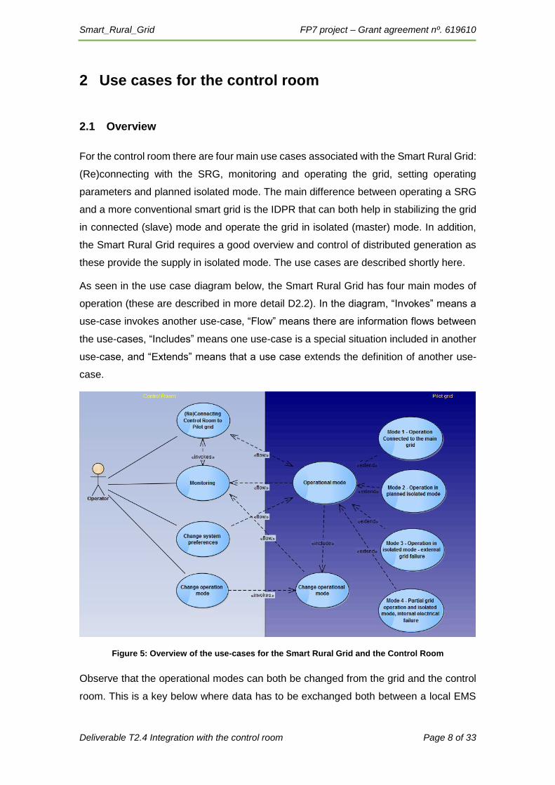
For the control room there are four main use cases associated with the Smart Rural Grid:
(Re)connecting with the SRG, monitoring and operating the grid, setting operating
parameters and planned isolated mode. The main difference between operating a SRG
and a more conventional smart grid is the IDPR that can both help in stabilizing the grid
in connected (slave) mode and operate the grid in isolated (master) mode. In addition,
the Smart Rural Grid requires a good overview and control of distributed generation as
these provide the supply in isolated mode. The use cases are described shortly here.
As seen in the use case diagram below, the Smart Rural Grid has four main modes of
operation (these are described in more detail D2.2). In the diagram, “Invokes” means a
use-case invokes another use-case, “Flow” means there are information flows between
the use-cases, “Includes” means one use-case is a special situation included in another
use-case, and “Extends” means that a use case extends the definition of another use-
case.
Figure 5: Overview of the use-cases for the Smart Rural Grid and the Control Room
Observe that the operational modes can both be changed from the grid and the control
room. This is a key below where data has to be exchanged both between a local EMS

Smart_Rural_Grid FP7 project – Grant agreement nº. 619610
Deliverable T2.4 Integration with the control room Page 9 of 33
and the control room, with both having the ability to change set points and operational
modes for the IDPR.
2.2 (Re)connecting to the Smart Rural Grid
In the event of lost connection or when the control room system starts, it is necessary to
establish connection with the SRG. This connection initiates the flow of push messages
from the grid components, and by default will invoke the “Monitoring and operating…”
use case.
2.3 Monitoring and operating the Smart Rural Grid
The operator will see the status of the study case on the display. He will need to clearly
see the operational mode of the study case (mode 1-4), and data from the electrical
components in the study area. In case of modes with electrical failure, the point of failure
will be shown in the system in best available detail. Position of switches, variables as
harmonics, voltage, battery status etc. will be displayed in the control room. Variables
that are outside “normal” boundaries will be slightly emphasized. Variables that are
outside normal boundaries and require manual operation will be strongly highlighted.
These variables will be pushed from the RTU to the control room at regular intervals (less
than 3 minutes). When the push signal is lost, a lost connection warning will be displayed
in the control room and the criticality of this warning will increase at certain intervals of
uninterrupted lost connection.
2.4 Changing operating parameters
Certain parameters on the IDPR can be changed from the control room (see list below).
The control room will then broadcast these parameters to the specified IDPR units. For
the pilot, parameters will be set both by Kisters EMS automatically based on an
optimization algorithm via the control room at regular intervals, and the local EMS.
2.5 Changing operating mode
For planned isolated mode (mode 2), the control room will set the operation mode
manually. The control room will then broadcast a signal to the local grid components to
change position of switches and signal IDPR and possibly generators.
Smart_Rural_Grid FP7 project – Grant agreement nº. 619610
Deliverable T2.4 Integration with the control room Page 10 of 33
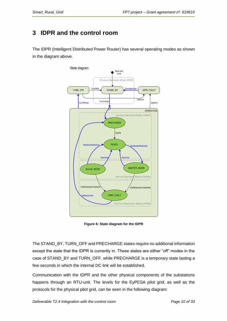
3 IDPR and the control room
The IDPR (Intelligent Distributed Power Router) has several operating modes as shown
in the diagram above.
OPERATION
READY
MASTER_MODESLAVE_MODE
GRID_FAULT
STAND_BY IDPR_FAULT
PRECHARGE
BusOK
StartSlaveModeOrder
StopOrder StopOrder
StartMasterModeOrder
GridParametersViolationSl GridParametersViolationMa
GetReadyOrder
TurnOnOrderTurnOffOrder
ResetIdprOrder
IdprError
State diagramBlack-start
point
Normal Operation Modes (NOMs)
TURN_OFFTurnOffOk
StartUp Operation Modes (SOMs)
Grid Fault Operation Mode (GFOM)
Previous Operation Mode (POM)
IdprError
Figure 6: State diagram for the IDPR
The STAND_BY, TURN_OFF and PRECHARGE states require no additional information
except the state that the IDPR is currently in. These states are either “off” modes in the
case of STAND_BY and TURN_OFF, while PRECHARGE is a temporary state lasting a
few seconds in which the internal DC link will be established.
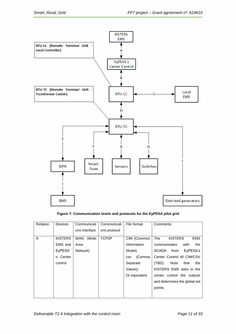
Communication with the IDPR and the other physical components of the substations
happens through an RTU-unit. The levels for the EyPESA pilot grid, as well as the
protocols for the physical pilot grid, can be seen in the following diagram:
Smart_Rural_Grid FP7 project – Grant agreement nº. 619610
Deliverable T2.4 Integration with the control room Page 11 of 33
Figure 7: Communication levels and protocols for the EyPESA pilot grid
Relation Devices Communicati
ons interface
Communicati
ons protocol
File format Comments
A KISTERS
EMS and
EyPESA’
s Center
control
WAN (Wide
Area
Network)
TCP/IP
CIM (Common
Information
Model)
csv (Comma
Separate
Values)
Or equivalent
The KISTERS EMS
communicates with the
SCADA from EyPESA’s
Center Control till CIM/CSV
(TBD). Note that the
KISTERS EMS asks to the
center control the outputs
and determines the global set
points.
Smart_Rural_Grid FP7 project – Grant agreement nº. 619610
Deliverable T2.4 Integration with the control room Page 12 of 33
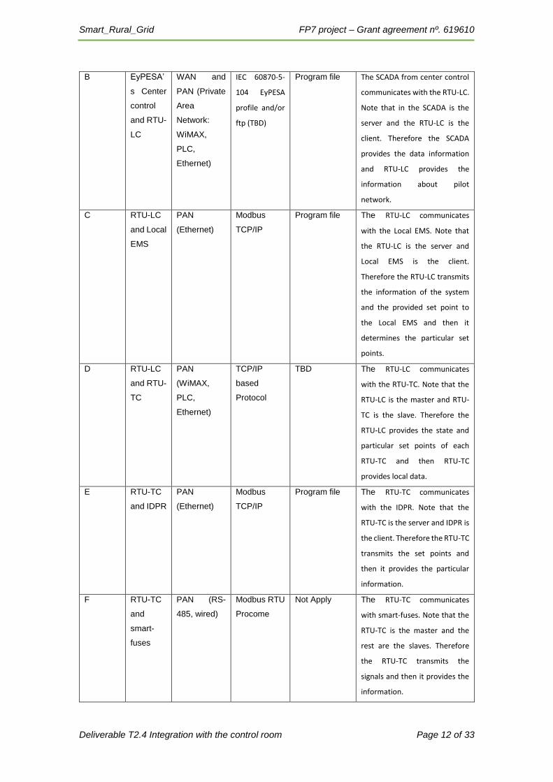
B EyPESA’
s Center
control
and RTU-
LC
WAN and
PAN (Private
Area
Network:
WiMAX,
PLC,
Ethernet)
IEC 60870-5-
104 EyPESA
profile and/or
ftp (TBD)
Program file
The SCADA from center control
communicates with the RTU-LC.
Note that in the SCADA is the
server and the RTU-LC is the
client. Therefore the SCADA
provides the data information
and RTU-LC provides the
information about pilot
network.
C RTU-LC
and Local
EMS
PAN
(Ethernet)
Modbus
TCP/IP
Program file
The RTU-LC communicates
with the Local EMS. Note that
the RTU-LC is the server and
Local EMS is the client.
Therefore the RTU-LC transmits
the information of the system
and the provided set point to
the Local EMS and then it
determines the particular set
points.
D RTU-LC
and RTU-
TC
PAN
(WiMAX,
PLC,
Ethernet)
TCP/IP
based
Protocol
TBD The RTU-LC communicates
with the RTU-TC. Note that the
RTU-LC is the master and RTU-
TC is the slave. Therefore the
RTU-LC provides the state and
particular set points of each
RTU-TC and then RTU-TC
provides local data.
E RTU-TC
and IDPR
PAN
(Ethernet)
Modbus
TCP/IP
Program file The RTU-TC communicates
with the IDPR. Note that the
RTU-TC is the server and IDPR is
the client. Therefore the RTU-TC
transmits the set points and
then it provides the particular
information.
F RTU-TC
and
smart-
fuses
PAN (RS-
485, wired)
Modbus RTU
Procome
Not Apply The RTU-TC communicates
with smart-fuses. Note that the
RTU-TC is the master and the
rest are the slaves. Therefore
the RTU-TC transmits the
signals and then it provides the
information.

Smart_Rural_Grid FP7 project – Grant agreement nº. 619610
Deliverable T2.4 Integration with the control room Page 13 of 33
G RTU-TC
and
sensors
PAN (RS-
485, wired)
Modbus RTU
Digital I/O
Analogue I/O
Not Apply The RTU-TC communicates
with sensors. Note that the
RTU-TC is the master and the
rest are the slaves. Therefore
the RTU-TC transmits the
signals and then it provides the
information.
H RTU-TC
and
switches
PAN (RS-
485, wired)
Modbus RTU
Digital I/O
Analogue I/O
Procome
Not Apply The RTU-TC communicates
with switches. Note that the
RTU-TC is the master and the
rest are the slaves. Therefore
the RTU-TC transmits the
signals and then it provides the
information.
I RTU-TC
and
distribute
d
generator
PAN
(WiMAX )
TCP/IP
based
protocol
TBD The RTU-TC communicates
with generators. Note that the
RTU-TC is the master and the
generators are the slaves.
Therefore the RTU-TC transmits
the signals and then it provides
the information.
J IDPR and
BMS
PAN (RS-
485)
TBD TBD The IDPR communicates with
Battery Management System.
Note that the IDPR is the server
and the BMS is the client.

Smart_Rural_Grid FP7 project – Grant agreement nº. 619610
Deliverable T2.4 Integration with the control room Page 14 of 33
3.1 IDPR as a sensor
The IDPR can in all states function as an advanced sensor. The following properties are
measured by the IDPR:
Description Units Format Availability
Load active power phase R [W] Real Master/Slave
Load active power phase S [W] Real Master/Slave
Load active power phase T [W] Real Master/Slave
Load reactive power phase R [var] Real Master/Slave
Load reactive power phase S [var] Real Master/Slave
Load reactive power phase T [var] Real Master/Slave
Grid active power phase R [W] Real Master/Slave
Grid active power phase S [W] Real Master/Slave
Grid active power phase T [W] Real Master/Slave
Grid reactive power phase R [var] Real Master/Slave
Grid reactive power phase S [var] Real Master/Slave
Grid reactive power phase T [var] Real Master/Slave
Rated apparent power scale factor [pu] Real Master/Slave
Grid phase R voltage [V] Real Master/Slave
Grid phase S voltage [V] Real Master/Slave
Grid phase T voltage [V] Real Master/Slave
Grid frequency [Hz] Real Master/Slave
Battery voltage [V] Real Master/Slave
Battery current [A] Real Master/Slave
Smart_Rural_Grid FP7 project – Grant agreement nº. 619610
Deliverable T2.4 Integration with the control room Page 15 of 33
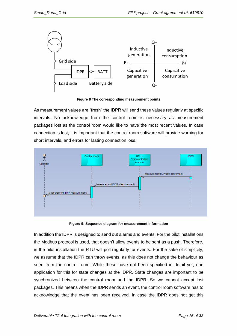
Figure 8 The corresponding measurement points
As measurement values are “fresh” the IDPR will send these values regularly at specific
intervals. No acknowledge from the control room is necessary as measurement
packages lost as the control room would like to have the most recent values. In case
connection is lost, it is important that the control room software will provide warning for
short intervals, and errors for lasting connection loss.
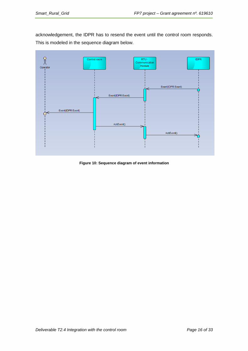
Figure 9: Sequence diagram for measurement information
In addition the IDPR is designed to send out alarms and events. For the pilot installations
the Modbus protocol is used, that doesn’t allow events to be sent as a push. Therefore,
in the pilot installation the RTU will poll regularly for events. For the sake of simplicity,
we assume that the IDPR can throw events, as this does not change the behaviour as
seen from the control room. While these have not been specified in detail yet, one
application for this for state changes at the IDPR. State changes are important to be
synchronized between the control room and the IDPR. So we cannot accept lost
packages. This means when the IDPR sends an event, the control room software has to
acknowledge that the event has been received. In case the IDPR does not get this
IDPR BATT
Grid side
Load side Battery side
Inductiveconsumption
Capacitiveconsumption
Capacitive generation
P+
Q+
Inductive generation
P-
Q-
Smart_Rural_Grid FP7 project – Grant agreement nº. 619610
Deliverable T2.4 Integration with the control room Page 16 of 33
acknowledgement, the IDPR has to resend the event until the control room responds.
This is modeled in the sequence diagram below.
Figure 10: Sequence diagram of event information

Smart_Rural_Grid FP7 project – Grant agreement nº. 619610
Deliverable T2.4 Integration with the control room Page 17 of 33
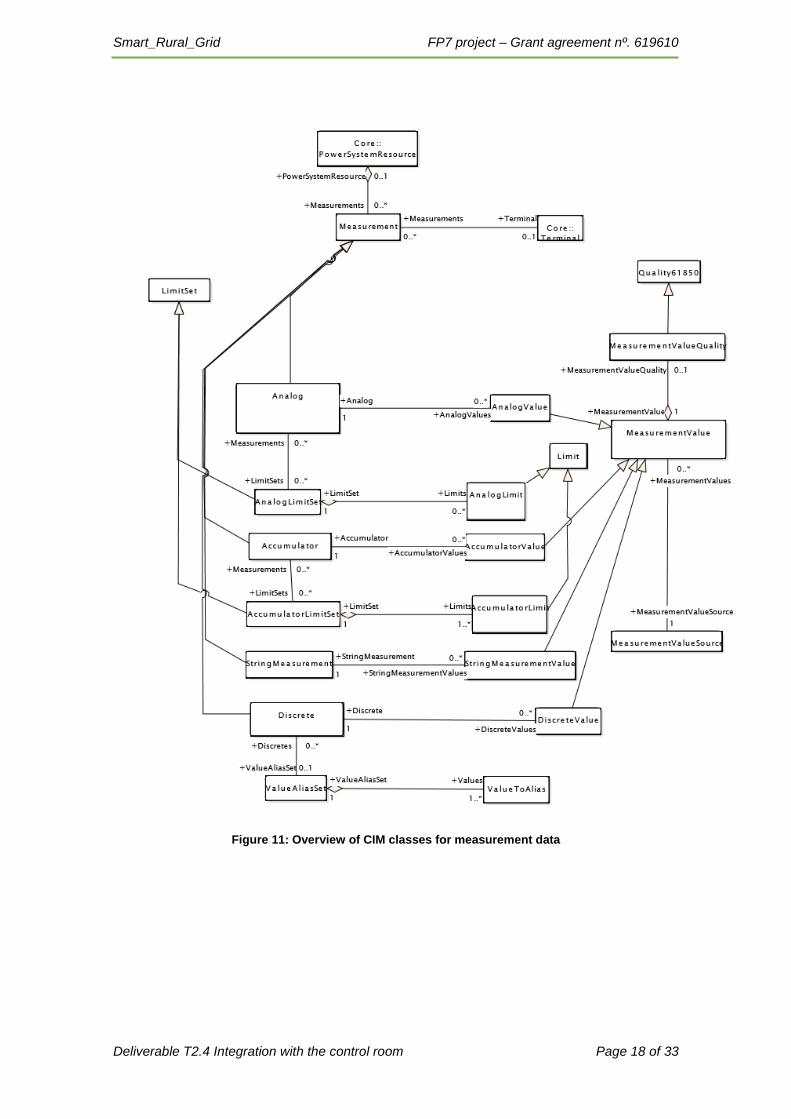
3.2 Modelling using CIM
The CIM-model has a structure for communicating measurements in SCADA/Control
room environments. The class structure is displayed in the UML diagram below. One the
left side the measurements are shown, with the abstract class Measurement, and
specialized classes for types of values. For the IDPR Analog (real) and Discrete (integer)
will be the most relevant. In cases where distinct values or events need to be sent, the
discreet values has the option of creating aliases. These aliases can e.g. be on/off states
of switches, or events reported by components in the grid. The diagram also shows the
relation between the measurement, and the values from the measurement (shown on
the right), All measurement values are also specialized classes of the abstract
MeasurmentValue class.
Smart_Rural_Grid FP7 project – Grant agreement nº. 619610
Deliverable T2.4 Integration with the control room Page 18 of 33
Figure 11: Overview of CIM classes for measurement data
Smart_Rural_Grid FP7 project – Grant agreement nº. 619610
Deliverable T2.4 Integration with the control room Page 19 of 33
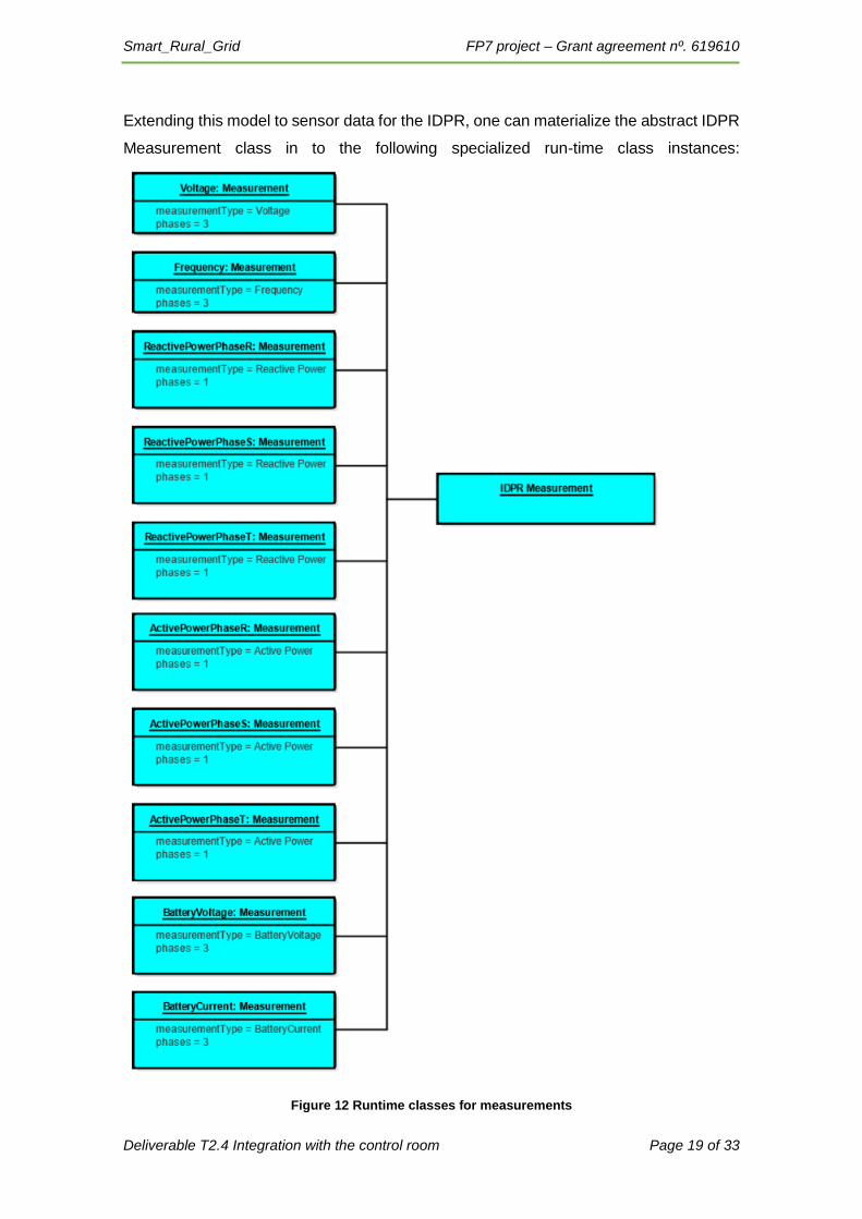
Extending this model to sensor data for the IDPR, one can materialize the abstract IDPR
Measurement class in to the following specialized run-time class instances:
Figure 12 Runtime classes for measurements
Smart_Rural_Grid FP7 project – Grant agreement nº. 619610
Deliverable T2.4 Integration with the control room Page 20 of 33
For Events (e.g. reporting events like changing states of the IDPR) there is no specific
classes in IEC61970 for handling these. These are instead handled as discreet values,
and these are then associated with aliases (e.g. “0” means Master mode).
3.3 IDPR as an active component
The IDPR will in certain modes stabilize or help stabilize the grid by monitoring active
and reactive power, voltage and frequency. In addition, in isolated modes the IDPR will
control the frequency, voltage and harmonics of the grid. In this case, both events need
to be communicated with the control room, as well as the control room needs to set
parameter and change operation modes.
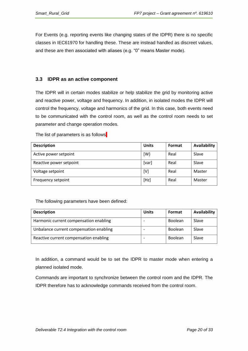
The list of parameters is as follows:
Description Units Format Availability
Active power setpoint [W} Real Slave
Reactive power setpoint [var] Real Slave
Voltage setpoint [V] Real Master
Frequency setpoint [Hz] Real Master
The following parameters have been defined:
Description Units Format Availability
Harmonic current compensation enabling - Boolean Slave
Unbalance current compensation enabling - Boolean Slave
Reactive current compensation enabling - Boolean Slave
In addition, a command would be to set the IDPR to master mode when entering a
planned isolated mode.
Commands are important to synchronize between the control room and the IDPR. The
IDPR therefore has to acknowledge commands received from the control room.

Smart_Rural_Grid FP7 project – Grant agreement nº. 619610
Deliverable T2.4 Integration with the control room Page 21 of 33
Figure 13: Sequence diagram for commands
The IDPR should be master source for the control states. This means in particular, that
when a connection is established with the IDPR, the IDPR reports current set-points
and status. In the sequence diagram below, IDPR Status is an abstract object in which
the IDPR reports set points and operational statuses. As a principle, historic values are
not reported to the control room.
Figure 14: Sequence diagram for connecting Control Room and IDPR
Smart_Rural_Grid FP7 project – Grant agreement nº. 619610
Deliverable T2.4 Integration with the control room Page 22 of 33
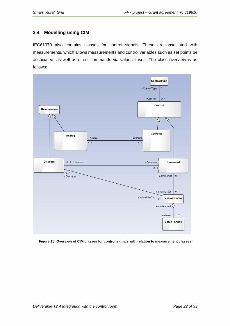
3.4 Modelling using CIM
IEC61970 also contains classes for control signals. These are associated with
measurements, which allows measurements and control variables such as set points be
associated, as well as direct commands via value aliases. The class overview is as
follows:
Figure 15: Overview of CIM classes for control signals with relation to measurement classes
Smart_Rural_Grid FP7 project – Grant agreement nº. 619610
Deliverable T2.4 Integration with the control room Page 23 of 33
4 Smart Rural Grid and the control room
Putting the IDPR in a smart rural grid adds to very important elements to the operation
of the Smart Rural Grid, The local EMS that can locally change set points, change
breakers and switches, and control the IDPR and local generators, and an optional
battery that are operated by the IDPR. For Grid Failure, the local EMS will ensure that
the IDPR goes to master mode, and in the event of several IDPR’s cooperating, setting
which is master and slaves in isolated mode.
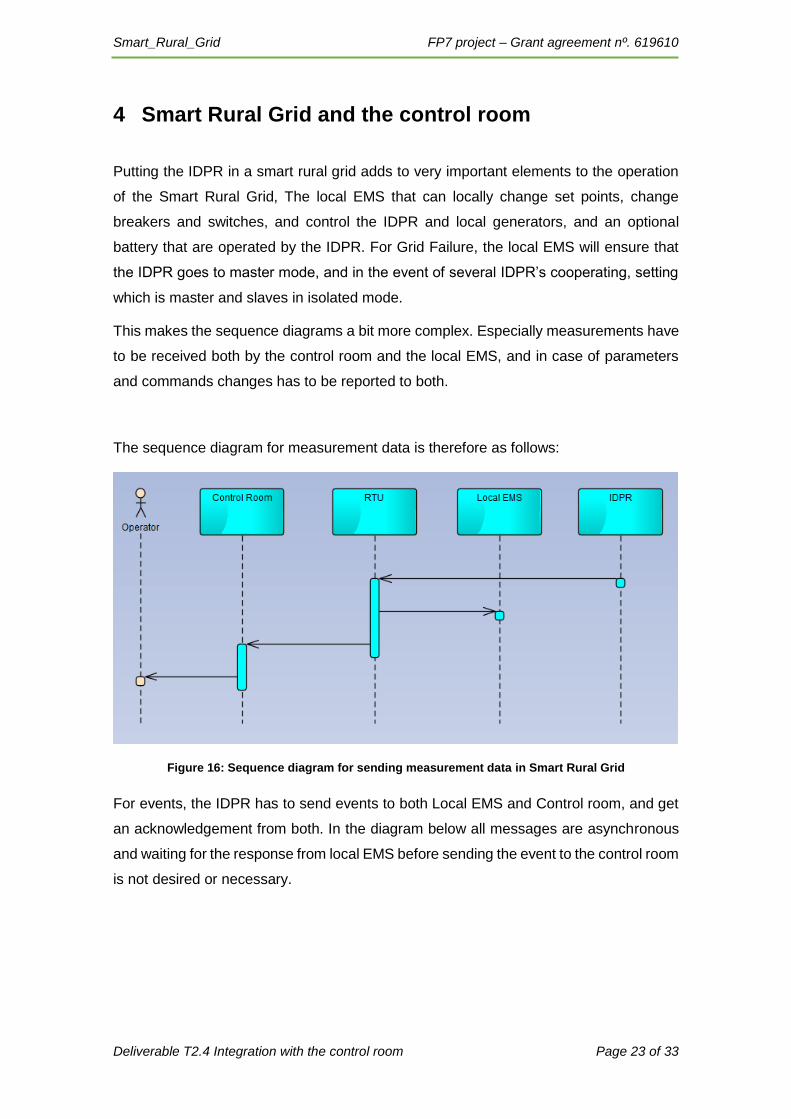
This makes the sequence diagrams a bit more complex. Especially measurements have
to be received both by the control room and the local EMS, and in case of parameters
and commands changes has to be reported to both.
The sequence diagram for measurement data is therefore as follows:
Figure 16: Sequence diagram for sending measurement data in Smart Rural Grid
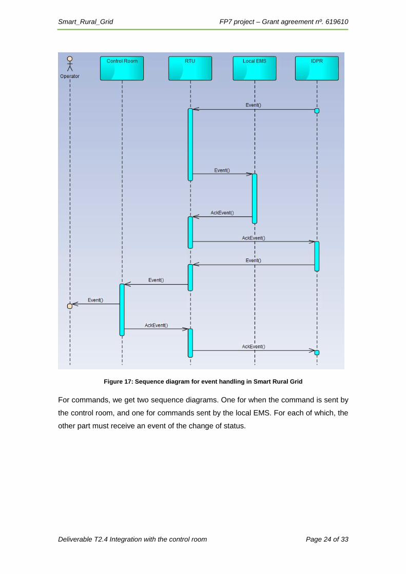
For events, the IDPR has to send events to both Local EMS and Control room, and get
an acknowledgement from both. In the diagram below all messages are asynchronous
and waiting for the response from local EMS before sending the event to the control room
is not desired or necessary.
Smart_Rural_Grid FP7 project – Grant agreement nº. 619610
Deliverable T2.4 Integration with the control room Page 24 of 33
Figure 17: Sequence diagram for event handling in Smart Rural Grid
For commands, we get two sequence diagrams. One for when the command is sent by
the control room, and one for commands sent by the local EMS. For each of which, the
other part must receive an event of the change of status.
Smart_Rural_Grid FP7 project – Grant agreement nº. 619610
Deliverable T2.4 Integration with the control room Page 25 of 33
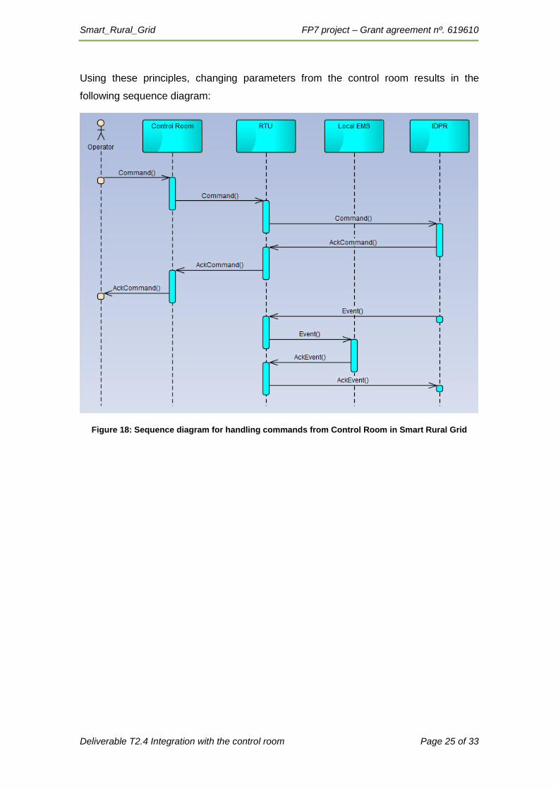
Using these principles, changing parameters from the control room results in the
following sequence diagram:
Figure 18: Sequence diagram for handling commands from Control Room in Smart Rural Grid
Smart_Rural_Grid FP7 project – Grant agreement nº. 619610
Deliverable T2.4 Integration with the control room Page 26 of 33
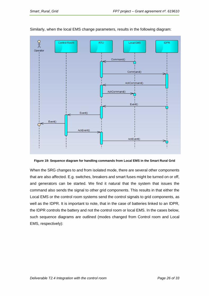
Similarly, when the local EMS change parameters, results in the following diagram:
Figure 19: Sequence diagram for handling commands from Local EMS in the Smart Rural Grid
When the SRG changes to and from isolated mode, there are several other components
that are also affected. E.g. switches, breakers and smart fuses might be turned on or off,
and generators can be started. We find it natural that the system that issues the
command also sends the signal to other grid components. This results in that either the
Local EMS or the control room systems send the control signals to grid components, as
well as the IDPR. It is important to note, that in the case of batteries linked to an IDPR,
the IDPR controls the battery and not the control room or local EMS. In the cases below,
such sequence diagrams are outlined (modes changed from Control room and Local
EMS, respectively):

Smart_Rural_Grid FP7 project – Grant agreement nº. 619610
Deliverable T2.4 Integration with the control room Page 27 of 33
Figure 20: Sequence Diagram for changing operational mode from the control room

Smart_Rural_Grid FP7 project – Grant agreement nº. 619610
Deliverable T2.4 Integration with the control room Page 28 of 33
Figure 21: Sequence diagram for changing operational mode from Local EMS
4.1 Smart Rural Grid pilot EyPESA
EyPESAs pilot grid is located in Catalonia in Spain, and consists of four substations (see
diagram below).
Smart_Rural_Grid FP7 project – Grant agreement nº. 619610
Deliverable T2.4 Integration with the control room Page 29 of 33
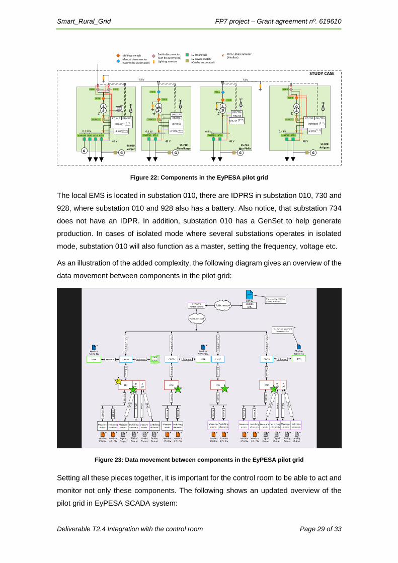
Figure 22: Components in the EyPESA pilot grid
The local EMS is located in substation 010, there are IDPRS in substation 010, 730 and
928, where substation 010 and 928 also has a battery. Also notice, that substation 734
does not have an IDPR. In addition, substation 010 has a GenSet to help generate
production. In cases of isolated mode where several substations operates in isolated
mode, substation 010 will also function as a master, setting the frequency, voltage etc.
As an illustration of the added complexity, the following diagram gives an overview of the
data movement between components in the pilot grid:
Figure 23: Data movement between components in the EyPESA pilot grid
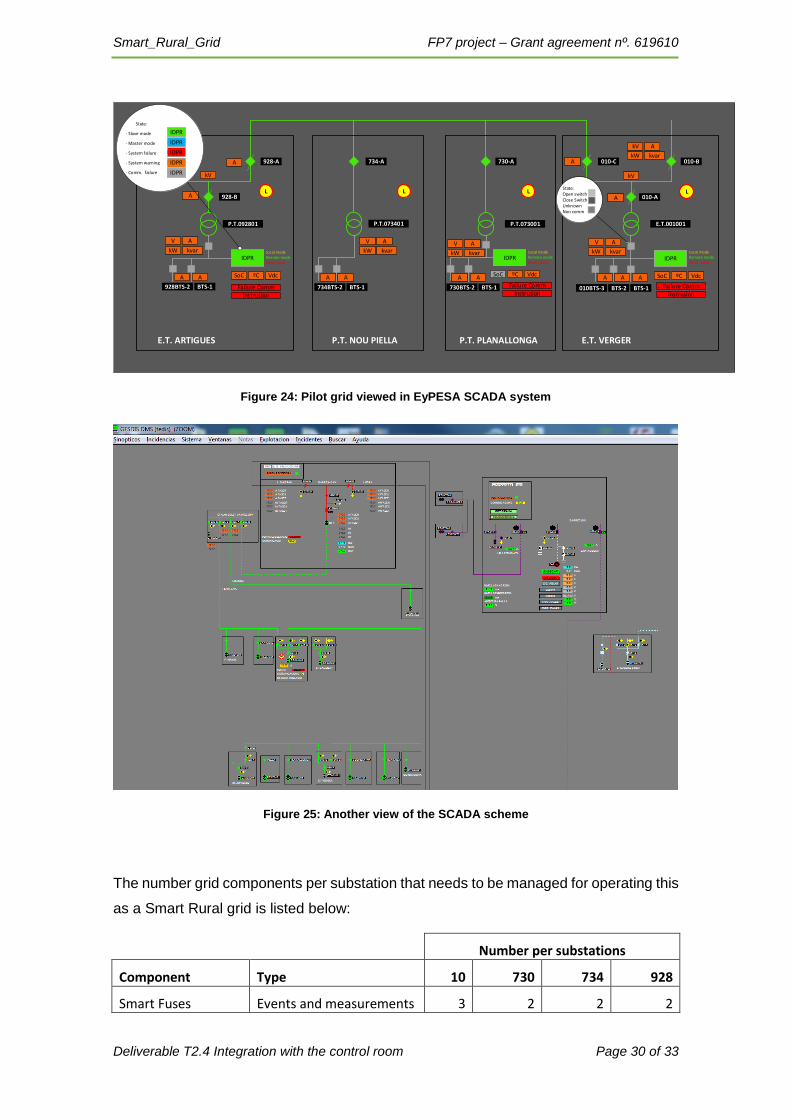
Setting all these pieces together, it is important for the control room to be able to act and
monitor not only these components. The following shows an updated overview of the
pilot grid in EyPESA SCADA system:
SS 730Planallonga
SS 734Nou Piella
SS 010Verger
STUDY CASE
0.4 kV0.4 kV0.4 kV0.23 kV
010-B 010-C
928-B
928-A
5 kV 5 kV
GG
730-A 734-A
928BTS-2 BTS-1730BTS-2 734BTS-2 BTS-1BTS-2 BTS-1
010BTT-1 928BTT-1730BTT-1
IDPR730 IDPR928
734-B730-B
BTS-3010BTS-4
G G G
IDPR010
SS 928Artigues
48 V 48 V
+
48 V 48 V
MV Fuse-switch Swith-disconnector(Can be automated)
Manual disconnector(Cannot be automated) Lighting arrester
LV Smart fuse
LV Power-switch(Can be automated)
+
DPLC734
Three-phase analizer (Modbus)
BTS-1
UPS010
DPLC010
010-A
Local EMS
UPS730
DPLC730
RTU730UPS734
RTU734
UPS730
DPLC730RTU010 RTU730
+
+
++
Smart_Rural_Grid FP7 project – Grant agreement nº. 619610
Deliverable T2.4 Integration with the control room Page 30 of 33
Figure 24: Pilot grid viewed in EyPESA SCADA system
Figure 25: Another view of the SCADA scheme
The number grid components per substation that needs to be managed for operating this
as a Smart Rural grid is listed below:
Number per substations
Component Type 10 730 734 928
Smart Fuses Events and measurements 3 2 2 2
928-B
928-A 734-A 730-A 010-C 010-B
010-A
E.T.001001P.T.073001P.T.073401P.T.092801
E.T. ARTIGUES P.T. NOU PIELLA P.T. PLANALLONGA E.T. VERGER
IDPR
VdcSoC ºC
kW
V A
kvar
VdcSoC ºC
kW
V A
kvar
VdcºC
kW
V A
kvarIDPRIDPR
kW
kV A
kvar
Local modeRemote modeBlock mode
Local modeRemote modeBlock mode
Local modeRemote modeBlock mode
010BTS-3 BTS-2 BTS-1730BTS-2 BTS-1734BTS-2 BTS-1928BTS-2 BTS-1
A
kV
A A A A SoCA A
kW
V A
kvar
A
kV
A A
A A A
L
Failure Comm
Instrusion
L L
Failure CommInstrusion
L
Failure CommInstrusion
State:Open switchClose SwitchUnknownNon comm
State:
- Slave mode
- Master mode
- System failure
- System warning
- Comm. failure
IDPR
IDPR
IDPR
IDPR
IDPR
Smart_Rural_Grid FP7 project – Grant agreement nº. 619610
Deliverable T2.4 Integration with the control room Page 31 of 33
LV switches Events 1 1 0 1
MV switches Events 2 0 0 1
MV switch breaker Events 1 0 0 1
IDPR Events and measurements 1 1 0 1
Batteries Events and measurements 1 0 0 1
UPS Events and measurements 1 1 1 1
Notice that there are two medium voltage switched in substation 10. The switch called
010-B, can disconnect all substations mentioned above from the main grid. So, by
operating this switch the entire pilot grid can be switched between isolated and grid
modes.
For the control room, it is important that all of these components can be associated as
one entity, that visually the SRG can be viewed both as a whole (indicating isolated or
connected modes, and warnings and errors) as well as individual components. As the
operation is more or less automatic, emphasis should be given foremost on the smart
rural grid rather than the individual components. In this scenario, the control room must
be aware of a Smart Rural Grid, with substations that contains components.
4.2 Smart Rural Grid Pilot SWRO
The second pilot grid, is in the area of Stadtwerke Rosenheim in Germany. An overview
of the pilot area can be seen below.
Smart_Rural_Grid FP7 project – Grant agreement nº. 619610
Deliverable T2.4 Integration with the control room Page 32 of 33
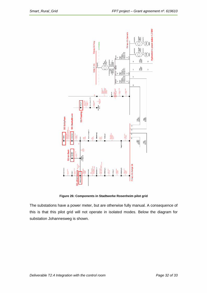
Figure 26: Components in Stadtwerke Rosenheim pilot grid
The substations have a power meter, but are otherwise fully manual. A consequence of
this is that this pilot grid will not operate in isolated modes. Below the diagram for
substation Johannesweg is shown.

Smart_Rural_Grid FP7 project – Grant agreement nº. 619610
Deliverable T2.4 Integration with the control room Page 33 of 33
Figure 27: Substation components in Stadtwerke Rosenheim pilot grid
In this mode of operation, the IDPR will function as a sensor and an active component
to help absorb reactive power etc. For the control room, the integration of components
is therefore not as important. For these cases the control room is more concerned of the
entity substation that has an active component (the IDPR).


![T2.4 [Computer Component- Communication Devices]](https://static.fdocuments.us/doc/165x107/577cde301a28ab9e78ae94f6/t24-computer-component-communication-devices.jpg)


