Assessment of Wind Turbine Seismic Risk: Existing Literature and ...
International Conference on Renewable Energies and Power Quality (ICREPQ’13) Bilbao (Spain), 20th to 22th March, 2013
Renewable Energy and Power Quality Journal (RE&PQJ)
ISSN 2172-038 X, No.11, March 2013
Small wind in urban sectors: Review of literature and dynamic model
implementation
Olatz Azurza, Pedro María García, Vicente Moreno, Julián Molina and Itziar Zubia
Department of Electrical Engineering UPV/EHU, University of the Basque Country
Campus of Gipuzkoa – Plaza Europa 1, 20.018 Donostia-San Sebastián (Spain) Phone/Fax number:+ 34 943 018 594, e-mail: [email protected]
Abstract. Large industry is focusing on off-shore wind
generation solutions which permit extra large turbine dimensions. In an economically recessing situation it may be sensible to underline the good results observed in distributed and local generation. Attending to consumer proximity, cities and urban areas are to be studied. These locations present renewable resource scarcity in general. However, several authors, following the evolution of regulations in countries like UK, present the advantages of small wind. From the point of view of generator concept options experimental comparative analysis’ results are included. Finally, a mathematical model for small radial flux permanent magnet synchronous generators (RF-PMSG) is included and verified by means of a contrasted simulator in Matlab Simulink. The implemented simulator will permit more accurate and analytical comparatives between small wind generator solutions.
Key words Small-wind, electric generator, urban areas
1. Introduction Large industry is focusing on off-shore wind generation solutions which permit extra large turbine dimensions[1], [2]. Scale factor allows reaching high efficiency rates in terms of generation to the mentioned research line[3]. However, off-shore generation points are necessarily located far from big consumers (cities and industries), and hence, they must be connected to transportation systems (which already present saturation problems together with inherent energy losses due to large distance transportation)[4]. In an economically recessing situation, where serious difficulties are observed for big project financing, it may be sensible to underline the good results observed in distributed generation, mini-grids and smart grids[4]–[6]. These solutions are more adapted to distribution grid connection and local generation. Attending to consumer proximity, cities and urban areas are to be studied. These locations present renewable
resource scarcity in general. However, several authors, following the evolution of regulations in countries like UK, present the advantages of small wind[7]–[15]. This paper collects the technical state of the art of the urban small wind sector and the diversity of generators used for this application. Additionally, it presents a valid analytical model for transient analysis of a radial flux permanent magnet synchronous generator (RF-PMSG), which has been implemented on Matlab Simulink. Results obtained by means of the simulator are briefly described, as well as future research lines.
2. Urban wind characteristics Compared to wide rural zones, urban areas experience turbulence and absence of prevailing wind direction. According to Acosta et al.[7], in urban areas, the distribution of wind speed is similar to a general Weibull distribution, whereas the speed in an open space corresponds better to a Rayleigh distribution. The review performed regarding urban wind resource measurement by Walker[8] confirms the difficulty of wind speed measurement in urban areas. A study performed by Ayhan et al.[9] demonstrates that wind velocity distribution around high-scrappers follows patterns depicted in Fig. 1 and Fig. 2. As can be derived from the previous figures, the optimal location around buildings for wind generation is the gap between two of them (Venturi effect).
Table I. Wind turbine classification [10].
Size Power [kW]
Tower height [m]
Micro 0 – 1.5 10 – 18
Small 1.5 – 15 12 – 25
Small-medium 15 – 100 15 – 50
https://doi.org/10.24084/repqj11.552 1130 RE&PQJ, Vol.1, No.11, March 2013
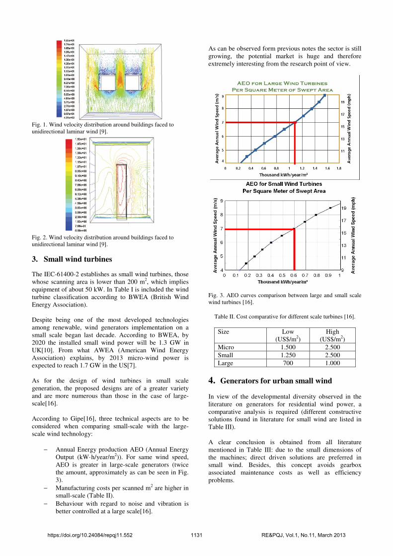
Fig. 1. Wind velocity distribution around buildings faced to unidirectional laminar wind [9].
Fig. 2. Wind velocity distribution around buildings faced to unidirectional laminar wind [9].
3. Small wind turbines
The IEC-61400-2 establishes as small wind turbines, those whose scanning area is lower than 200 m2, which implies equipment of about 50 kW. In Table I is included the wind turbine classification according to BWEA (British Wind Energy Association). Despite being one of the most developed technologies among renewable, wind generators implementation on a small scale began last decade. According to BWEA, by 2020 the installed small wind power will be 1.3 GW in UK[10]. From what AWEA (American Wind Energy Association) explains, by 2013 micro-wind power is expected to reach 1.7 GW in the US[7]. As for the design of wind turbines in small scale generation, the proposed designs are of a greater variety and are more numerous than those in the case of large-scale[16]. According to Gipe[16], three technical aspects are to be considered when comparing small-scale with the large-scale wind technology:
− Annual Energy production AEO (Annual Energy Output (kW·h/year/m2)). For same wind speed, AEO is greater in large-scale generators (twice the amount, approximately as can be seen in Fig. 3).
− Manufacturing costs per scanned m2 are higher in small-scale (Table II).
− Behaviour with regard to noise and vibration is better controlled at a large scale[16].
As can be observed form previous notes the sector is still growing, the potential market is huge and therefore extremely interesting from the research point of view.
Fig. 3. AEO curves comparison between large and small scale wind turbines [16].
Table II. Cost comparative for different scale turbines [16].
Size Low (US$/m2)
High (US$/m2)
Micro 1.500 2.500
Small 1.250 2.500
Large 700 1.000
4. Generators for urban small wind In view of the developmental diversity observed in the literature on generators for residential wind power, a comparative analysis is required (different constructive solutions found in literature for small wind are listed in Table III). A clear conclusion is obtained from all literature mentioned in Table III: due to the small dimensions of the machines; direct driven solutions are preferred in small wind. Besides, this concept avoids gearbox associated maintenance costs as well as efficiency problems.
https://doi.org/10.24084/repqj11.552 1131 RE&PQJ, Vol.1, No.11, March 2013
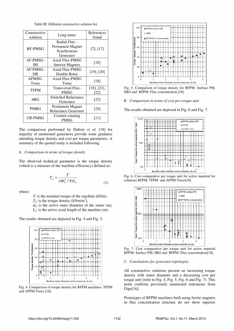
Table III. Different constructive solution list
Constructive solution
Long name References
found
RF-PMSG
Radial Flux - Permanent Magnet
Synchronous Generator
[7], [17]
AF-PMSG-IM
Axial Flux-PMSG Interior Magnets
[18]
AF-PMSG-DR
Axial Flux-PMSG Double Rotor
[19], [20]
APMSG-Torus
Axial Flux-PMSG Torus
[18]
TFPM Transversal Flux-
PMSG [18], [21],
[22]
SRG Switched Reluctance
Generator [23]
PMRG Permanent Magnet
Reluctance Generator [24]
CR-PMSG Counter-rotating
PMSG [11]
The comparison performed by Dubois et al. [18] for majority of mentioned generators provide some guidance attending torque density and cost per torque parameters. A summary of the quoted study is included following. A. Comparison in terms of torque density
The observed technical parameter is the torque density (which is a measure of the machine efficiency) defined as:
a
dLd
TT
)4/( 2
0π=
(1) where:
T: is the nominal torque of the machine (kNm), Td: is the torque density (kNm/m3), d0: is the active outer diameter of the stator (m), La: is the active axial length of the machine (m).
The results obtained are depicted in Fig. 4 and Fig. 5.
Fig. 4. Comparison of torque density for RFPM machines, TFPM and AFPM-Torus [18].
Fig. 5. Comparison of torque density for RFPM- Surface PM, SRG and RFPM- Flux concentration [18].
B. Comparison in terms of cost per torque unit
The results obtained are depicted in Fig. 6 and Fig. 7.
Fig. 6. Cost comparative per torque unit for active material for solutions RFPM, TFPM and AFPM-Torus[18].
Fig. 7. Cost comparative per torque unit for active material RFPM- Surface PM, SRG and RFPM- Flux concentration[18].
C. Conclusions for generator topologies
All constructive solutions present an increasing torque density with stator diameter and a decreasing cost per torque unit (refer to Fig. 4, Fig. 5, Fig. 6 and Fig. 7). This point confirms previously mentioned statements from Gipe[16]. Prototypes of RFPM machines built using ferrite magnets in flux concentration structure do not show superior
https://doi.org/10.24084/repqj11.552 1132 RE&PQJ, Vol.1, No.11, March 2013
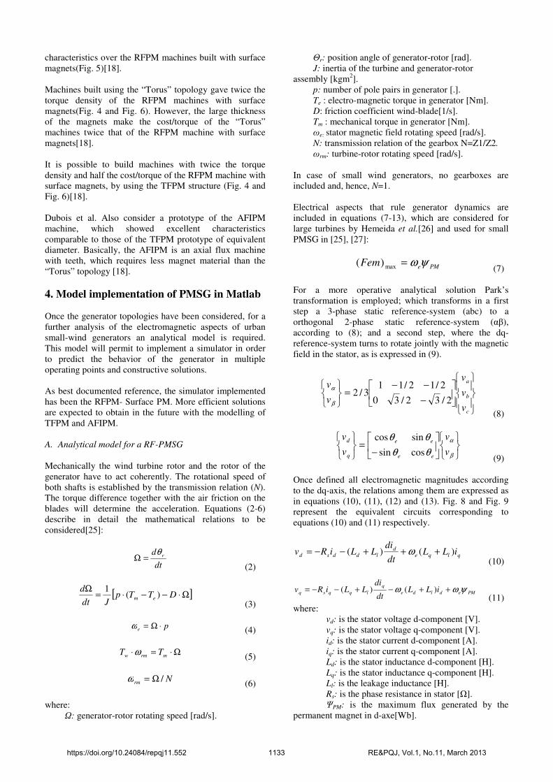
characteristics over the RFPM machines built with surface magnets(Fig. 5)[18]. Machines built using the “Torus” topology gave twice the torque density of the RFPM machines with surface magnets(Fig. 4 and Fig. 6). However, the large thickness of the magnets make the cost/torque of the “Torus” machines twice that of the RFPM machine with surface magnets[18]. It is possible to build machines with twice the torque density and half the cost/torque of the RFPM machine with surface magnets, by using the TFPM structure (Fig. 4 and Fig. 6)[18]. Dubois et al. Also consider a prototype of the AFIPM machine, which showed excellent characteristics comparable to those of the TFPM prototype of equivalent diameter. Basically, the AFIPM is an axial flux machine with teeth, which requires less magnet material than the “Torus” topology [18].
4. Model implementation of PMSG in Matlab Once the generator topologies have been considered, for a further analysis of the electromagnetic aspects of urban small-wind generators an analytical model is required. This model will permit to implement a simulator in order to predict the behavior of the generator in multiple operating points and constructive solutions. As best documented reference, the simulator implemented has been the RFPM- Surface PM. More efficient solutions are expected to obtain in the future with the modelling of TFPM and AFIPM. A. Analytical model for a RF-PMSG
Mechanically the wind turbine rotor and the rotor of the generator have to act coherently. The rotational speed of both shafts is established by the transmission relation (N). The torque difference together with the air friction on the blades will determine the acceleration. Equations (2-6) describe in detail the mathematical relations to be considered[25]:
dt
d rθ=Ω
(2)
[ ]Ω⋅−−⋅=Ω
DTTpJdt
dem )(
1
(3)
pe ⋅Ω=ω (4)
Ω⋅=⋅ mrmw TT ω
(5)
Nrm /Ω=ω
(6) where:
Ω: generator-rotor rotating speed [rad/s].
Θr: position angle of generator-rotor [rad]. J: inertia of the turbine and generator-rotor
assembly [kgm2]. p: number of pole pairs in generator [.]. Te : electro-magnetic torque in generator [Nm]. D: friction coefficient wind-blade[1/s]. Tm : mechanical torque in generator [Nm]. ωe: stator magnetic field rotating speed [rad/s]. N: transmission relation of the gearbox N=Z1/Z2.
ωrm: turbine-rotor rotating speed [rad/s]. In case of small wind generators, no gearboxes are included and, hence, N=1. Electrical aspects that rule generator dynamics are included in equations (7-13), which are considered for large turbines by Hemeida et al.[26] and used for small PMSG in [25], [27]:
PMeFem ψω=max)( (7)
For a more operative analytical solution Park’s transformation is employed; which transforms in a first step a 3-phase static reference-system (abc) to a orthogonal 2-phase static reference-system (αβ), according to (8); and a second step, where the dq-reference-system turns to rotate jointly with the magnetic field in the stator, as is expressed in (9).
−
−−=
c
b
a
v
v
v
v
v
2/32/30
2/12/113/2
β
α
(8)
−=
β
α
θθ
θθ
v
v
v
v
ee
ee
q
d
cossin
sincos
(9) Once defined all electromagnetic magnitudes according to the dq-axis, the relations among them are expressed as in equations (10), (11), (12) and (13). Fig. 8 and Fig. 9 represent the equivalent circuits corresponding to equations (10) and (11) respectively.
qlqe
d
lddsd iLLdt
diLLiRv )()( +++−−= ω
(10)
PMedlde
q
lqqsq iLLdt
diLLiRv ψωω ++−+−−= )()(
(11) where:
vd: is the stator voltage d-component [V]. vq: is the stator voltage q-component [V]. id: is the stator current d-component [A]. iq: is the stator current q-component [A]. Ld: is the stator inductance d-component [H]. Lq: is the stator inductance q-component [H]. Ll: is the leakage inductance [H]. Rs: is the phase resistance in stator [Ω]. ΨPM: is the maximum flux generated by the
permanent magnet in d-axe[Wb].
https://doi.org/10.24084/repqj11.552 1133 RE&PQJ, Vol.1, No.11, March 2013
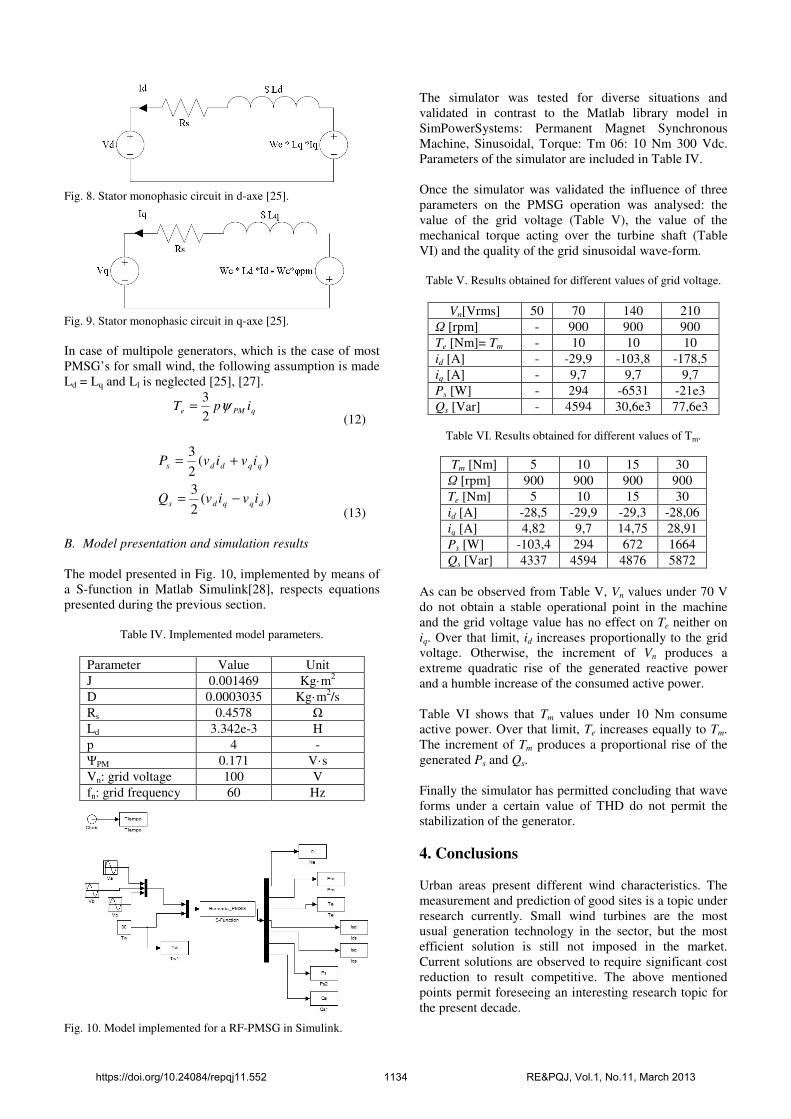
Fig. 8. Stator monophasic circuit in d-axe [25].
Fig. 9. Stator monophasic circuit in q-axe [25].
In case of multipole generators, which is the case of most PMSG’s for small wind, the following assumption is made Ld = Lq and Ll is neglected [25], [27].
qPMe ipT ψ
2
3=
(12)
)(
2
3
)(2
3
dqqds
qqdds
ivivQ
ivivP
−=
+=
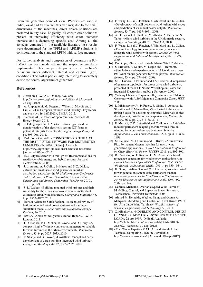
(13) B. Model presentation and simulation results
The model presented in Fig. 10, implemented by means of a S-function in Matlab Simulink[28], respects equations presented during the previous section.
Table IV. Implemented model parameters.
Parameter Value Unit
J 0.001469 Kg·m2
D 0.0003035 Kg·m2/s
Rs 0.4578 Ω
Ld 3.342e-3 H
p 4 -
ΨPM 0.171 V·s
Vn: grid voltage 100 V
fn: grid frequency 60 Hz
Fig. 10. Model implemented for a RF-PMSG in Simulink.
The simulator was tested for diverse situations and validated in contrast to the Matlab library model in SimPowerSystems: Permanent Magnet Synchronous Machine, Sinusoidal, Torque: Tm 06: 10 Nm 300 Vdc. Parameters of the simulator are included in Table IV. Once the simulator was validated the influence of three parameters on the PMSG operation was analysed: the value of the grid voltage (Table V), the value of the mechanical torque acting over the turbine shaft (Table VI) and the quality of the grid sinusoidal wave-form.
Table V. Results obtained for different values of grid voltage.
Vn[Vrms] 50 70 140 210
Ω [rpm] - 900 900 900
Te [Nm]= Tm - 10 10 10
id [A] - -29,9 -103,8 -178,5
iq [A] - 9,7 9,7 9,7
Ps [W] - 294 -6531 -21e3
Qs [Var] - 4594 30,6e3 77,6e3
Table VI. Results obtained for different values of Tm.
Tm [Nm] 5 10 15 30
Ω [rpm] 900 900 900 900
Te [Nm] 5 10 15 30
id [A] -28,5 -29,9 -29,3 -28,06
iq [A] 4,82 9,7 14,75 28,91
Ps [W] -103,4 294 672 1664
Qs [Var] 4337 4594 4876 5872
As can be observed from Table V, Vn values under 70 V do not obtain a stable operational point in the machine and the grid voltage value has no effect on Te neither on iq. Over that limit, id increases proportionally to the grid voltage. Otherwise, the increment of Vn produces a extreme quadratic rise of the generated reactive power and a humble increase of the consumed active power. Table VI shows that Tm values under 10 Nm consume active power. Over that limit, Te increases equally to Tm. The increment of Tm produces a proportional rise of the generated Ps and Qs. Finally the simulator has permitted concluding that wave forms under a certain value of THD do not permit the stabilization of the generator.
4. Conclusions Urban areas present different wind characteristics. The measurement and prediction of good sites is a topic under research currently. Small wind turbines are the most usual generation technology in the sector, but the most efficient solution is still not imposed in the market. Current solutions are observed to require significant cost reduction to result competitive. The above mentioned points permit foreseeing an interesting research topic for the present decade.
https://doi.org/10.24084/repqj11.552 1134 RE&PQJ, Vol.1, No.11, March 2013
From the generator point of view, PMSG’s are used in radial, axial and transversal flux variants; due to the small dimensions of the machines, direct driven solutions are preferred in any case. Logically, all constructive solutions present an increasing efficiency with stator diameter increase and a decreasing specific cost. Among all the concepts compared in the available literature best results were documented for the TFPM and AFIMP solutions in consideration to the standard RFPM with surface magnets. For further analysis and comparison of generators a RF-PMSG has been modelled and the respective simulator implemented. This one permits prediction of machine’s behaviour under different internal and external (grid) conditions. This last is particularly interesting to accurately define the control algorithm of generators.
References [1] «Offshore | EWEA». [Online]. Available:
http://www.ewea.org/policy-issues/offshore/. [Accessed: 27-aug-2012].
[2] A. Arapogianni, M. Dragan, J. Wilkes, J. Moccia and J. Guillet, «The European offshore wind industry - key trends and statistics 1st half 2012», EWEA, 2012.
[3] Siemens AG, «Oceans of opportunities», Siemens AG Energy Sector, 2011.
[4] S. Erlinghagen and J. Markard, «Smart grids and the transformation of the electricity sector: ICT firms as potential catalysts for sectoral change», Energy Policy, 51, pp. 895–906, 2012.
[5] Task Force C6.04.01, «CONNECTION CRITERIA AT THE DISTRIBUTION NETWORK FOR DISTRIBUTED GENERATION», 2007. [Online]. Available: http://www.cigre.org/Publications/Technical-Brochures. [Accessed: 07-jun-2012].
[6] IEC, «Hydro sector with mini grids: Recommendations for small renewable energy and hybrid systems for rural electrification». 2003.
[7] J. L. Acosta, A. J. Collin, B. Hayes and S. Z. Djokic, «Micro and small-scale wind generation in urban distribution networks», in 7th Mediterranean Conference
and Exhibition on Power Generation, Transmission,
Distribution and Energy Conversion (MedPower 2010), 2010, pp. 1–9.
[8] S. L. Walker, «Building mounted wind turbines and their suitability for the urban scale—A review of methods of estimating urban wind resource», Energy and Buildings, 43, 8, pp 1852–1862, 2011.
[9] Dursun Ayhan eta Safak Saglam, «A technical review of buildingmounted wind power systems and a sample simulation model», Renewable and Sustainable Energy
Reviews, 16, 2012. [10] BWEA, «Small Wind Systems Market Report», BWEA,
London, 2011. [11] J. D. Booker, P. H. Mellor, R. Wrobel and D. Drury, «A
compact, high efficiency contra-rotating generator suitable for wind turbines in the urban environment», Renewable
Energy, 35, 9, pp 2027–2033, 2010. [12] T. Sharpe and G. Proven, «Crossflex: Concept and early
development of a true building integrated wind turbine», Energy and Buildings, 42, 12, 2365–2375, 2010.
[13] F. Wang, L. Bai, J. Fletcher, J. Whiteford and D. Cullen, «Development of small domestic wind turbine with scoop and prediction of its annual power output», Renewable
Energy, 33, 7, pp. 1637–1651, 2008. [14] A. D. Peacock, D. Jenkins, M. Ahadzi, A. Berry and S.
Turan, «Micro wind turbines in the UK domestic sector», Energy and Buildings, 40, 7, 1324–1333, 2008.
[15] F. Wang, L. Bai, J. Fletcher, J. Whiteford and D. Cullen, «The methodology for aerodynamic study on a small domestic wind turbine with scoop», Journal of Wind
Engineering and Industrial Aerodynamics, 96, 1, 1–24, 2008.
[16] Paul Gipe, «Small and Household-size Wind Turbines». . [17] S. Eriksson, A. Solum, M. Leijon andH. Bernhoff,
«Simulations and experiments on a 12 kW direct driven PM synchronous generator for wind power», Renewable
Energy, 33, 4, pp. 674–681, 2008. [18] M.R. Dubois, H. Polinder and J.A. Ferreira, «Comparison
of generator topologies for direct-drive wind turbines», presented at the IEEE Nordic Workshop on Power and Industrial Electronics,, Aalborg University, 2000.
[19] Yicheng Chen eta Pragasen Pillay, «Axial-flux PM Wind Generator with A Soft Magnetic Composite Core», IEEE, 2005.
[20] L. Mishnaevsky Jr., P. Freere, R. Sinha, P. Acharya, R. Shrestha and P. Manandhar, «Small wind turbines with timber blades for developing countries: Materials choice, development, installation and experiences», Renewable
Energy, 36, 8, pp. 2128–2138, 2011. [21] E. Muljadi, C. P. Butterfield and Y.-H. Wan, «Axial-flux
modular permanent-magnet generator with a toroidal winding for wind-turbine applications», Industry
Applications, IEEE Transactions on, 35, 4, pp. 831 –836, 1999.
[22] M. Bellucci, V. I. Cimino and R. Rizzo, «A Transverse Flux Permanent Magnet machine for micro-wind generation application», in 2011 International Conference
on Clean Electrical Power (ICCEP), 2011, pp. 802–806. [23] R. Cardenas, W. F. Ray and G. M. Asher, «Switched
reluctance generators for wind energy applications», in Power Electronics Specialists Conference, 1995. PESC
’95 Record., 26th Annual IEEE, 1995, 1, pp 559 –564 . [24] H. Goto, Hai-Jiao Guo and O. Ichinokura, «A micro wind
power generation system using permanent magnet reluctance generator», in 13th European Conference on
Power Electronics and Applications, 2009. EPE ’09, 2009, pp. 1–8.
[25] Gabriele Michalke, «Variable Speed Wind Turbines - Modelling, Control, and Impact on Power Systems», Technischen Universität Darmstadt, 2008.
[26] Ahmed M. Hemeida, Wael A. Farag, and Osama A. Mahgoub, «Modeling and Control of Direct Driven PMSG for Ultra Large Wind Turbines», World Academy of
Science, Engineering and Technology, 59, 2011. [27] Z. Mihailovic, «MODELING AND CONTROL DESIGN
OF VSI-FED PMSM DRIVE SYSTEMS WITH ACTIVE LOAD», 22-apr-1999. [Online]. Available: http://scholar.lib.vt.edu/theses/available/etd-031899-212402/. [Accessed: 30-aug-2012].
[28] «MathWorks España - MATLAB and Simulink for Technical Computing». [Online]. Available: http://www.mathworks.es/. [Accessed: 19-sept-2012].
https://doi.org/10.24084/repqj11.552 1135 RE&PQJ, Vol.1, No.11, March 2013