sm Sharp AR-M 280
40
This document was been published to faciliate after sales service only. The contents are subject to change without notice. Parts marked with “ “ are important for maintaining the safety of the machine. To maintain the safety and performance of the machine, use only the replacement parts specified. SHARP CORPORATION LASER PRINTER MODEL AR-M280U/M280N CODE : 00ZARM280UA1E [1] INTRODUCTION These models are a modified version of the AR-M350U/M350N, providing a different printing speed. This Service Manual, therefore, describes only the different points from the AR-M350U/M350N and supplementary items. For items which are not described in this Service Manual, refer to the following Service Manuals and Parts Guides. Note:Depending on the option, additional service documentation may be required. [2] LIST OF DIFFERENCES FROM AR-M350U/N A.Product composition *1: Installation of the AR-P14 on U-series machines provides functions equivalent to the M-series machines. •AR-M350/M450 Service Manual : 00ZARM350/A1E Parts Guide : 00ZARM450/P1E Circuit Diagram : 00ZARM350/C1/ •AR-P350/P450 Service Manual : 00ZARP350/A2E Parts Guide : 00ZAR350LPP1/ Circuit Diagram : 00ZARP350/C1/ •AR-M350U/N•AR-M450U/N Service Manual : 00ZARM350UA1E •AR-NC5J Service Manual : 00ZARNC5J/A1E Model Name Network Printer Option Model NIC Standard Model Note Base Engine AR-M350U AR-M280U AR-M350N AR-M280N Print Speed 35ppm 28ppm 35ppm 28ppm Multi Function Controller AR-M11 Not Available Not Available Standard Standard Multi Function Controller(for U-Model) Standard Standard Not Available Not Available No registered as a product Print Server Card AR-NC5J Option Option Standard Standard Printer Extension Kit AR-P14 Option Option Standard Standard *1 Hardware MFP-ROM Only U-type 35/45ppm Only U-type 28ppm Only M-type 35/45ppm Only M-type 28ppm
-
Upload
rostocanie -
Category
Documents
-
view
65 -
download
1
Transcript of sm Sharp AR-M 280

This document was been published to faciliateafter sales service only.The contents are subject to change without notice.
Parts marked with “ “ are important for maintaining the safety of the machine.
To maintain the safety and performance of the machine, use only the replacement parts specified.
SHARP CORPORATION
LASER PRINTER
MODEL AR-M280U/M280N
CODE : 00ZARM280UA1E
[1] INTRODUCTION
These models are a modified version of the AR-M350U/M350N, providing a different printing speed.This Service Manual, therefore, describes only the different points from the AR-M350U/M350N and supplementary items.For items which are not described in this Service Manual, refer to the following Service Manuals and Parts Guides.
Note:Depending on the option, additional service documentation may be required.
[2] LIST OF DIFFERENCES FROM AR-M350U/N
A.Product composition
*1: Installation of the AR-P14 on U-series machines provides functions equivalent to the M-series machines.
•AR-M350/M450 Service Manual : 00ZARM350/A1E Parts Guide : 00ZARM450/P1E Circuit Diagram : 00ZARM350/C1/
•AR-P350/P450 Service Manual : 00ZARP350/A2E Parts Guide : 00ZAR350LPP1/ Circuit Diagram : 00ZARP350/C1/
•AR-M350U/N•AR-M450U/N Service Manual : 00ZARM350UA1E
•AR-NC5J Service Manual : 00ZARNC5J/A1E
Model Name Network Printer Option Model NIC Standard Model Note
Base Engine AR-M350U AR-M280U AR-M350N AR-M280N
Print Speed 35ppm 28ppm 35ppm 28ppm
Multi Function Controller AR-M11 Not Available Not Available Standard Standard
Multi Function Controller(for U-Model) Standard Standard Not Available Not Available No registeredas a product
Print Server Card AR-NC5J Option Option Standard Standard
Printer Extension Kit AR-P14 Option Option Standard Standard *1
Hardware MFP-ROM Only U-type35/45ppm
Only U-type28ppm
Only M-type35/45ppm
Only M-type28ppm
!

AR-M280U CONFIGURATION 3-1
[3] CONFIGURATION
1.System Configurations
2. StandardCategory Model Name Other options required for the installation/mounting.
(Options must be ordered separately.)Remarks
MFP model (35ppm) AR-M350 • B/W Scanner module/DSPF (AR-EF1)• Scanner Rack(AR-RK1)• Stand/MPD&2000 sheet paper drawer (AR-D13) or Three paper drawer stand (AR-D14)
• Power supply unit (AR-DC1)
MFP model (45ppm) AR-M450
MFP model (28ppm) (Without network printer function) AR-M280U
MFP model (35ppm) (Without network printer function) AR-M350U
MFP model (45ppm) (Without network printer function) AR-M450U
MFP model (28ppm) (With NIC card (standard)) AR-M280N
MFP model (35ppm) (With NIC card (standard)) AR-M350N
MFP model (45ppm) (With NIC card (standard)) AR-M450N
B/W scanner module/DSPF(AR-EF1)
Upper exit tray extension(AR-TE4)
Finisher(AR-FN6)
Mail-bin stacker(AR-MS1)
Stand/MPD & 2000 sheet paper drawer
(AR-D13)Stand/3 x 500 sheet
paper drawer(AR-D14)
Saddle stitch finisher(AR-FN7)
Duplex module(AR-DU3)
Duplex module/bypasstray(AR-DU4)
Exit tray(AR-TE3 or AR-DU4 Standard)
Power supply unit(AR-DC1)
!"#$%#&
AR-M280U CONFIGURATION 3-2
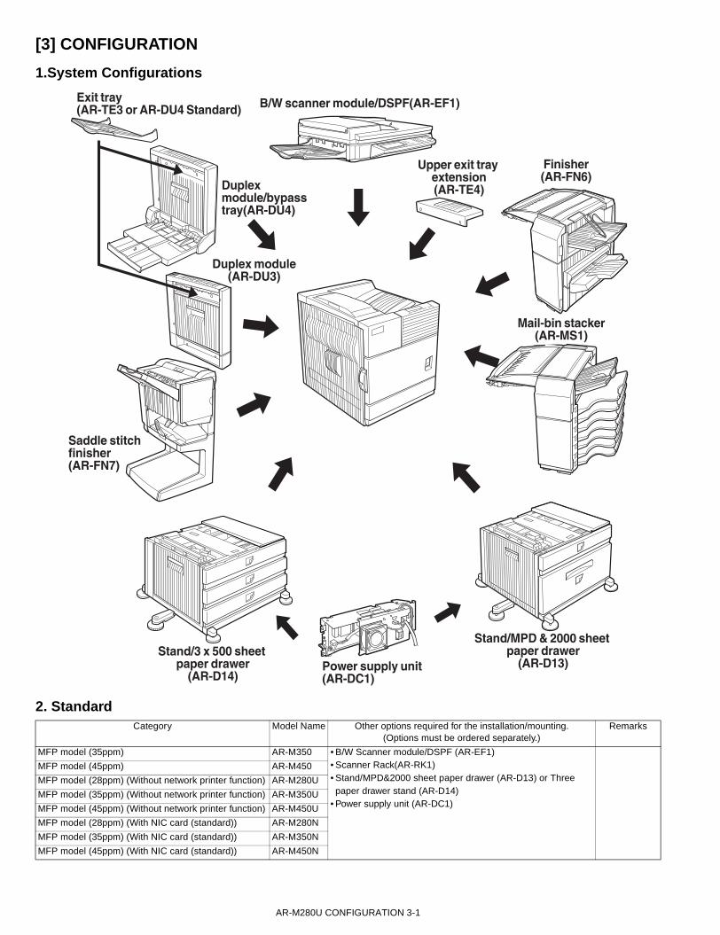
3. List of combination of peripheral devicesA.AR-M280U
As shown in the table below, some other peripheral devices ( B ) may be needed for installation of a peripheral device ( A ) and some peripheral devicescannot be installed together.
Related for scanner feature
Related for paper feed unit
B/W scanner module/DSPF AR-EF1
AR-RK1
AR-D14
AR-D13
AR-DU4
AR-DU3
AR-FN7AR-FN6
AR-MS1
AR-TE3
AR-TE4
AR-PN1
AR-PK1
AR-NS2
AR-FX5
AR-MM9
AR-DC1
AR-HD3
AR-M11
AR-NC5J
AR-P14
Scanner rackS
cann
er r
ack
Stand/3 x 500 sheet paper drawer
Stand/MPD & 2000 sheet paper drawer
Saddle stitch finisher
Finisher
Mail-bin stacker
Exit tray
Punch unit
PS3 expansion kit
Facsimile expansion kit
PrNetwork printer kit
int server card
Hard disk drive
Power supply unit
Duplex module/bypass tray
Duplex module
Sta
nd/3
x 5
00 s
heet
pap
er d
raw
er
Sta
nd/M
PD
& 2
000
shee
t
Dup
lex
mod
ule/
bypa
ss tr
ay
Dup
lex
mod
ule
Upper exit tray extension
Multi-function controllerboard
Fax memory (8 MB)
B/W
sca
nner
mod
ule/
DS
PF
Sad
dle
stitc
h fin
ishe
r
Fin
ishe
r
Mai
l-bin
sta
cker
Exi
t tra
y
Pun
ch u
nit
PS
3 ex
pans
ion
kit
Facs
imile
exp
ansi
on k
it
Pri
nt s
erve
r ca
rd
Har
d di
sk d
r
Net
wor
k pr
inte
r ki
t
ive
Pow
er s
uppl
y un
it
Upp
er e
xit t
ray
exte
nsio
n
Mul
ti-fu
nctio
n co
ntro
ller
boar
d
Fax
mem
ory
(8 M
B)
Network scanner expansion kit
Net
wor
k sc
anne
r exp
ansi
on k
it
*1
*2
*2
*1
*1
*1
*1
*1
*1
*1
*1
*1
*1
*1
*1
*2
*1
*1
*1
Output units
Related for extension offunctions and others
= Must be installed together.= Any of the units must be installed together.= Must be installed for installation of the stand/3 x 500 sheet paper drawer or the stand/MPD & 2000 sheet paper drawer.
= Cannot be installed together.= Standard= AR-DU4 Standard= Attachment of the AR-P14 provides the similar functions.
A
B
*4
*5
*6
*3*4*5
= Not Available*6
' !"#$%#&

AR-M280U CONFIGURATION 3-3
B.AR-M280N
As shown in the table below, some other peripheral devices ( B ) may be needed for installation of a peripheral device ( A ) and some peripheral devicescannot be installed together.
Related for scanner feature
Related for paper feed unit
B/W scanner module/DSPF AR-EF1
AR-RK1
AR-D14
AR-D13
AR-DU4
AR-DU3
AR-FN7AR-FN6
AR-MS1
AR-TE3
AR-TE4
AR-PN1
AR-PK1
AR-NS2
AR-FX5
AR-MM9
AR-DC1
AR-HD3
AR-M11
AR-NC5J
AR-P14
Scanner rackS
canner
rack
Stand/3 x 500 sheet paper drawer
Stand/MPD & 2000 sheet paper drawer
Saddle stitch finisher
Finisher
Mail-bin stacker
Exit tray
Punch unit
PS3 expansion kit
Facsimile expansion kit
PrNetwork printer kit
int server card
Hard disk drive
Power supply unit
Duplex module/bypass tray
Duplex module
Sta
nd/3
x 5
00 s
heet
pap
er d
raw
er
Sta
nd/M
PD
& 2
000 s
heet
Duple
x m
odule
/byp
ass
tra
y
Duple
x m
odule
Upper exit tray extension
Multi-function controllerboard
Fax memory (8 MB)
B/W
sca
nner
module
/DS
PF
Saddle
stit
ch fin
isher
Fin
isher
Mail-
bin
sta
cker
Exi
t tr
ay
Punch
unit
PS
3 e
xpansi
on k
it
Facs
imile
exp
ansi
on k
it
Pri
nt se
rver
card
Hard
dis
k dr
Netw
ork
printe
r ki
t
ive
Pow
er
supply
unit
Upper
exit
tray
ext
ensi
on
Mul
ti-fu
nctio
n co
ntro
ller
boar
d
Fax
mem
ory
(8 M
B)
Network scanner expansion kit
Net
wor
k sc
anne
r exp
ansi
on k
it
*1
*1
*1 *2
*2
*1
*1
*1
*1
*1
*1
*1
*1
*1
*2
*1
*1
*1
Output units
Related for extension offunctions and others
= Must be installed together.= Any of the units must be installed together.= Must be installed for installation of the stand/3 x 500 sheet paper drawer or the stand/MPD & 2000 sheet paper drawer.
= Cannot be installed together.= Standard= AR-DU4 Standard= Cannot be attached.
A
B
*4
*3
*3*6
*3*4*6
!"#$%#&

AR-M280U SPECIFICATIONS 4-1
[4] SPECIFICATIONS1. Basic SpecificationA. Base Engine
(1) Form
(2) Engine speed
(3) Engine composition
(4) Engine resolution
(5) Printable areaThe print area of this product is shown below.
If a printer driver for Windows or Macintosh is used for printing, theprintable area will be smaller. The actual printable area depends on theprinter driver to be used.
(in mm)
(6) Warm-up
(7) Power source
(8) Power consumption
(9) Energy Star benchmark
(10) Noise
* Showing noise benchmark in each model as a whole system.
(11) Dimensions
*1: With B/W scanner module/DSPF, Scanner rack, Large capacitypaper feed desk, Power supply unit and Upper exit tray extension
AR-M280U/M280N Console type
Paper size AR-M280U/N
A4, 8.5" x 11" 28ppm
A5R/5.5" x 8.5"R 28ppm
B5 28ppm
B4/8.5" x 14 16ppm
A3/11" x 17" 14ppm
Photoconductor type OPC (diameter of photoconductor : ø30mm)Record method Electrophotograph (laser)Development method Dry-type dual-component magnetic brush
developmentCharge method Charged saw-tooth methodTransfer method Transfer rollerCleaning method Cleaner bladeFusing method Heat rollerUsed toner disposal Toner recycling system
Resolution Write :600dpiSmoothing Write :1200dpi equivalentGradation Write :2 levels
CC
E
E
B
DA
Paper size
Printable area
Paper size A B C D E
A3 297 420 4 289 4
B4 257 364 4 242 4
A4 210 297 4 202 4
B5 182 257 4 168 4
A5 148 210 4 140 4
Japanese postcard 100 148 4 92 4
Ledger 279 432 4 271 4
Legal 216 356 4 208 4
Foolscap 216 330 4 208 4
Letter 216 279 4 208 4
Executive 184 267 4 183 4
Invoice 140 216 4 132 4
Com-10(envelope) 105 241 4 97 4
C5(envelope) 162 229 4 154 4
Monarch(envelope) 98 191 4 90 4
DL(envelope) 110 220 4 102 4
ISO B5(envelope) 176 250 4 168 4
Warm-up time less than 80 secondsPre-heat requirement RequiredJam recovery time Target: about 30 seconds
(Under standard condition of 60 seconds left after side cover opening, polygon motor halt)
Voltage 100V system100-127V
Frequency 50/60Hz
Max. Power consumption. 1440W(When MFP full system)
Low power mode 30W or below
Transition time to low power mode 30min
At working less than 6.8B
At waiting mode less than 5.0B
External dimensions(WxDxH)
428x552x469 (Only main unit) (mm)16.9"x21.7"x18.5"
Occupied space dimensions(WxD)
963x685 (mm) *125.7"x22.3"
Weight AR-M280U:Approx.38.9kg(including developing unit/process/each controller)Approx.99kg *1AR-M280N:Approx.39.9kg (including developing unit/process/each controller/NIC)Approx.100kg *1
!"#$%%&

AR-M280U SPECIFICATIONS 4-2
B. Document Feeding Equipment
(1) One-drawer tray (included in the base engine)
C. Output Equipment
(1) Face-down Exit Tray (included in the base engine)
2. Specific FunctionA. Printer Function
(1) Platform
* For Macintosh OS, the PS3 expansion kit and NIC card are required.
(2) Support OS
* For Macintosh OS, the PS3 expansion kit and NIC card are required.
(3) PDL emulation
(4) Print Function
a. General
b. Paper input
c. Paper output
d. Graphic
e. Font
Paper feed method One-drawer traySizes to be fed A4, B5, 8.5" x 11"Paper capacity 500 sheets (at 80g/m²)Media available for paper feeding
Plain paper 60 - 105g/m², 16 - 28lbs
Paper type Plain, recycled, pre-printed, pre-punched, color, letter head
Paper size switching To be switched by user (paper size to be entered from the operation panel).
Dehumidification heater
Not provided
Balance detection Provided (paper empty and 3 steps)Default size setting 100V system 200V system
8.5" x 11" A4Mounting/dismounting of the tray
Provided
Output position/method
Face-down output at the upper side of main unit
Output paper capacity 400 sheets (80g/m² sheet)Output paper size A3, B4, A4, A4R, B5, B5R, A5R
11 " x 17", 8.5" x 14", 8.5" x 13", 8.5" x 11 ", 8.5" x 11 "R, 5.5" x 8.5"RExecutive, postal card, Monarch (98 x 191) Com-10 (105 x 241), DL (110 x 220), C5 (162 x 229), ISO B5 (176 x 250)
Spec of media for paper output
Tracing paper : 52 ~ 59g/m² / 14 ~ 15lbsPlain paper : 60 ~ 128g/m² / 16 ~ 34lbsIndex paper : 176g/m² / 47lbsCover paper : 205g/m² / 54 ~ 55lbsTransparency film
Remaining paper detection
Not provided
Exit tray full detection Provided
IBM PC/AT (Include compatible machine)Macintosh (680x0), Power Macintosh, iMac, G3Macintosh
Custom PS Windows 95/98/Me/XPWindows NT 4.0Windows 2000
CustomPCL5e/6(XL)SPDL
Windows 95/98/Me/XPWindows NT 4.0Windows 2000
PPD Windows 95/98/Me/XPWindows NT 4.0Windows 2000Mac OS 8.5.1 - Mac OS 9
PCL6, PCL5e compatible, PostScript Level 2, PostScript 3 compatible(PS3 expansion kit is required.)
When an optional PS3 expansion kit is installed
Function PCL5e/PCL6
PS PPD (Windows)
PPD (Macintosh)
Copies 1 - 999 1 - 999 1 - 999 1 - 999
Orientation Yes Yes Yes Yes
Duplex print Yes Yes Yes Yes
Saddle stitch Yes Yes No N/A
Binding edge Left/top/right
Left/top/right
Long/short Long/short
N-up 2/4/6/8 2/4/6/8 2/4*3*4 2/4/6/9/16
N-up direction Fixed Fixed Fixed Selectable
N-up border line Yes Yes Yes(always) Yes
When an optional PS3 expansion kit is installed
Function PCL5e/PCL6
PS PPD (Windows)
PPD (Macintosh)
Paper size Yes Yes Yes Yes
Custom paper size 1 size 1 size 3 sizes*3*5 N/A
Source selection Yes Yes Yes Yes
Different first page Yes Yes N/A Yes
Transparency inserts Yes Yes N/A Yes
When an optional PS3 expansion kit is installed
Function PCL5e/PCL6
PS PPD (Windows)
PPD (Macintosh)
Output tray selection Yes Yes Yes Yes
Mail bin Yes Yes Yes Yes
Staple Yes Yes Yes Yes
Offset Yes Yes Yes Yes
Punch Yes Yes Yes Yes
When an optional PS3 expansion kit is installed
Function PCL5e/PCL6
PS PPD (Windows)
PPD (Macintosh)
Resolution 600/300 dpi
600 dpi 600 dpi 600 dpi
Halftone N/A Yes Yes N/A
Graphic mode Yes N/A N/A N/A
Smoothing Yes Yes Yes Yes
Toner save Yes Yes Yes Yes
Photo enhancement Yes*8 Yes N/A N/A
Negative image N/A Yes Yes Yes
Mirror image N/A Horizontal/vertical
Horizontal Yes
Zoom N/A N/A Yes Yes
Fit to page Yes Yes N/A N/A
When an optional PS3 expansion kit is installed
Function PCL5e/PCL6
PS PPD (Windows)
PPD (Macintosh)
Resident font 45 fonts 136 fonts 136 fonts*6 35 fonts
Download font Bitmap TrueType, Graphic
Bitmap Type1 TrueType
Bitmap Type1 TrueType
N/A
& !"#$%

AR-M280U SPECIFICATIONS 4-3
f. Others
* 1 For models without a hard disk drive, an optional hard disk drive(AR-HD3) must be installed .
* 2 Functions when peripheral devices are installed.* 3 Not supported in the Windows NT 4.0 environment.* 4 2/4/6/9/16 is supported in the Windows 2000 environment.* 5 Only one size is supported in the Windows 2000 environment.* 6 Only 35 fonts are supported in the Windows NT 4.0 environment.* 7 This function is limited for PPD.* 8 PCL6 only
(5) Compatibility
B. Expanded RAM
Installation of additional RAM will provide the following:1) Time out error reduction2) Spool time reduction 3) Avoidance of Virtual Memory (VM) error / memory fullUse commercially available RAM with the following specifications.Note: If RAM used does not meet the follow specifications, the copier
may not recognize the additional RAM or its capacity correctly.
<Specification>
<Operation-assured Memory> (As of March / 2001)
C. Scanner function
*Scanner function, the NIC card and Network Scanner kit are required.
(1) Scanner function
(2) Support System
(3) Support Image
(4) Transmission Mode
(5) Image Process
(6) Original Memory
(7) Specified Destination
(8) Specified Multiple Destinations
O : Available
When an optional PS3 expansion kit is installed
Function PCL5e/PCL6
PS PPD (Windows)
PPD (Macintosh)
Watermark*7 Yes Yes Yes Yes
Overlay Yes Yes N/A N/A
Job retention*1 Yes Yes N/A Yes
Account control Yes Yes N/A Yes
Custom settings Yes Yes N/A N/A
Automatic configuration*2
Yes Yes N/A Yes
Job end notification Yes Yes N/A N/A
PCL 5e compatibility
Target for PCL5e is to be compatible with HP LaserJet 4000.Small margin difference, rendering difference by different font family, default and transfer function difference are not to be included in the compatibility.All the PJL commands are not necessarily included in the compatibility.
PCL6 compatibility
Target for PCL6 is to be compatible with HP LaserJet 4000.Small margin difference, rendering difference by different font family, default and transfer function difference are not to be included in the compatibility.All the PJL commands are not necessarily included in the compatibility.
PostScript Compatibility
Roman PostScript is targeted to be compatible with Adobe PostScript as performed in HP LaserJet 4000.Small margin difference, rendering difference by different font family, default and transfer function difference are not to be included in the compatibility.
DIMM TYPE 168pin 3.3V Unbuffered SDRAM DIMM Non-ECC
DIMM capacity 64MByte, 128MByte, 256MByte
CAS LATENCY CL=2
SDRAM CLOCK For PC100, PC133
SPD Supporting
Parity Not support
ECC Not support
Manufacture Capacity Model name RAM CHIP name Note
Kingston Technology
128MB KVR133X64C3/128 HYB39S64800BT-7.5
128MB KVR133X64C3-128 D456821G-A75-9JF
256MB KVR133X64C3-256 HY57V28820AT-H
Viking Components
64MB VIK8641CL2 µPD456841G5-A80-9JF
64MB VIK8641CL2 D456841G5-A80-9JF
128MB VIK6642CL2 TC59SM708FT-80
128MB VIK6642CL2 D4564841G5-A80-9JF
256MB VIK2642CL2 TC59SM708FT-80
Memory Card Technology
64MB DM864VS65804X-7G
GM72V66841XT75
128MB DM1665VS65804X-7G
HY57V64820HG
Scanner mode Scan to E-mail (Internet FAX)Scan to Server (Client PC)
Embedded server SMTP serverFTP server
Protocol TCP/IP
Format TIFF, PDF, TIFF-F* Selectable for each page
Compression method Uncompressed, G3(1-dimension) *1, G4 *2*1 G3 (1-dimension) = MH (Modified Huffman)*2 G4 = MMR (Modified MR)
DSPF/OC transmission switching
Available(Switching during the reading is not possible)
Half tone reproduction Equivalent to 256 levelsExposure adjustment Light / Auto / DarkQuality selection Half-tone ON/OFFResolution* Normal ( 200x200dpi )
Fine ( 300x300dpi )Super fine ( 400x400dpi )Ultra fine ( 600x600dpi )Varies with the file type/transmission method
Standard Commonly use ERDH area of memory.Memory expansion Special : As per ERDH memory
Specified destination Specifying by one-touch or groupOne-touch* Max. 500 destinations
(in conjunction with the one-touch dial of FAX)Max. 100 destinations can be registered for FTP and Desktop.
Group* To be registered in one-touchProgram Available
Specified destination Specifying by one-touch or groupNo. of registration Max. 300 items
(in conjunction with those of FAX)Sequential broadcasting
Available(E-mail only. It is not available for FTP/Desktop.)
Simultaneous FAX transmission
Available(Specifying multiple destinations of FAX, E-mail or FTP and broadcasting by a single scan)
' !"#$%
AR-M280U SPECIFICATIONS 4-4
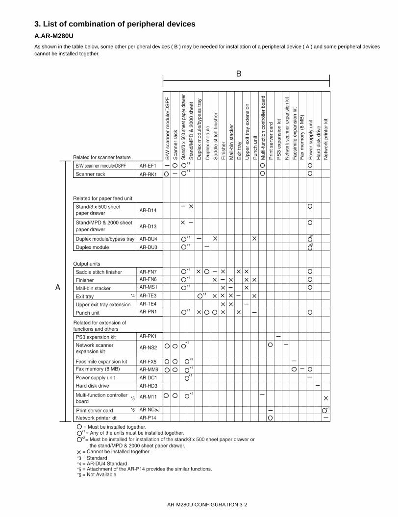
(9) Functions
D. Copy function
(1) Copy Speed
* Figures in reduction/enlargement are represented by those at theratio to show slowest speed
(2) First Copy TimeConditions: A4 or 8.5"x11"P from front tray of PPC, without HDD and
with polygon motor running.
*1 During OC/high-speed mode
(3) Job Speed
*1 S S : A4 / 8.5" x 11"P original 5 sheets copy 5sets*2 S D : A4 / 8.5" x 11"P original 10 sheets copy 5sets*3 D D : A4 / 8.5" x 11"P original 5 sheets (10 pages) copy 5sets
Note:First copy time has been factored into calculation resulting inreduced CPM.
(4) Continuous Copy
(5) Copy Ratio
(6) Exposure/Copy Quality Process
(7) Copy Function
Transmitting functions
Rotating transmission Available(to be matched with FAX specification)
Long length original transmission
Not Available
Verification stamp function OptionReport/list functions
Transmit/receive record AvailableTransmit/receive result AvailableAddress/phone directory list
Available
Group list AvailableID/sender list AvailableProgram list Available
Actual Reduction Enlargement
A4, 8.5"x11" 28 28 28
A4R, 8.5"x11"R 20 20 20
A5R, 5.5"x8.5"R,Invoice-R
28 28 28
B5 28 28 28
B5R, Exective-R 20 20 20
B4, 8.5"x14" 16 16 16
A3, 11"x17" 14 14 14
Extra, Envelope 14 14 14
Japan P/C When printing on post cards, engine speed can vary with system configuration, because each card is fed only after the previous card exits machine.
Document glass *1 Less than 5.3 seconds
DSPF Less than 6.0 seconds
S S *1 27 cpm (97%)
S D *2 26 cpm (92%)
D D *3 26 cpm (92%)
Max. multiple number 999 pages
Copy ratio AB series : 25%, 70%, 81%, 86%, 100%, 115%, 122%, 141%, 400%Inch series : 25%, 64%, 77%, 100%, 121%, 129%, 400%
Zoom 25 - 400%25 - 200% (Copy from DSPF)
Independentscaling
Not provided
Exposure mode Binary: Text(auto/manual), Text/photo, Photo256 levels: Not provided
Manual steps 9 stepsSmoothing StandardToner save mode Standard
Function APS Standard FunctionAMS Standard FunctionPaper type select Standard Function
(By type setting)Auto tray switching Standard FunctionRotation copy Standard FunctionElectronic sort Standard FunctionRotation sort Not providedReserved copy Standard FunctionPrior tray setting Not providedRecall/register of program Standard FunctionProof copy Not providedPreheat function Standard Function
(To be set up by key operator)
Auto power shut-off function Standard Function(To be set up by the key operator program)
Account control Standard Function(100 accounts)
Communication support (RIC) Standard FunctionCard counter support Only
provided the connectorCoin vendor support Only
provided the connectorSpecial function
Margin shift Standard FunctionEdge erase / Center erase Standard FunctionDual page copying Standard FunctionCovers Not providedTransparency insert Not providedCentering Not providedMulti shot (N in 1) Standard Function
(2 in 1 / 4 in 1)Pamphlet copy Standard Function2-sided copy orientation change Standard FunctionLarge capacity original mode 0 (Max. 140 pages)B/W reverse Not providedShading Not providedMirror image Not providedRepeat Not providedDate stamp Not providedStamp Not providedPage stamp Not providedZaurus print Not provided
!"#$%

AR-M280U CONSUMABLE PARTS 5-1
[5] CONSUMABLE PARTS1.Supply system tableNote: The consumable parts are the same as those of the AR-M350/M450 series and the AR-P350/P450.
A.USA
*1: For USA*2: Equivalent to the drum life.
Note1: Print on Master/individual carton:Toner/Developer in 2 languages (English/French), DR in 4 languages (English/French/German/Spanish).Note2: Packed with machine: DR 80K/Developer UN/Process UNNote3: The other maintenance parts which are not listed above are registered as service parts.
NO Name Content Life Product name Remark1 Toner (Black) Toner(Toner : Net Weight 814g) 27K AR-450NT
(*1 AR-450NT-J)*Life setup is based on A4 6%
2 Developer Developer(Developer : Net Weight 450g) 80K AR-450ND3 Drum Drum x1 80K AR-451DR4 Maintenance kit 1 Cleaner blade
Drum separation pawlScreen gridToner reception sealSide molt FSide molt RCharging plate
x1x4x1x1x1x1x1
80K *2 AR-450KC1
5 Maintenance kit 2 Transfer rollerDischarging platePaper dust removing unitDV bladeDV side seal FDV side seal R
x1x1x1x1x1x1
80K AR-450KA1
6 Upper heat roller kit Upper heat rollerFusing separation pawl (Upper)
x1x4
160K AR-450UH
7 Lower heat roller kit Lower heat rollerFusing separation pawl (Lower)
x1x2
160K AR-450LH
8 Cleaner blade Cleaner blade x10 80K*2(x10) AR-450CB Available in the National Parts Center
9 Cleaning roller Cleaning rollerBearing
x10x20
160K(x10) AR-450CR Available in the National Parts Center
10 Staple cartridge Staple cartridge x3 3000x3 AR-SC1 Common with cartridge for AR-FN4 & AR-FN6
11 Staple cartridge Staple cartridge x3 5000x3 AR-SC2 Common with cartridge for AR-FN7
"# $%&'()
AR-M280U CONSUMABLE PARTS 5-2
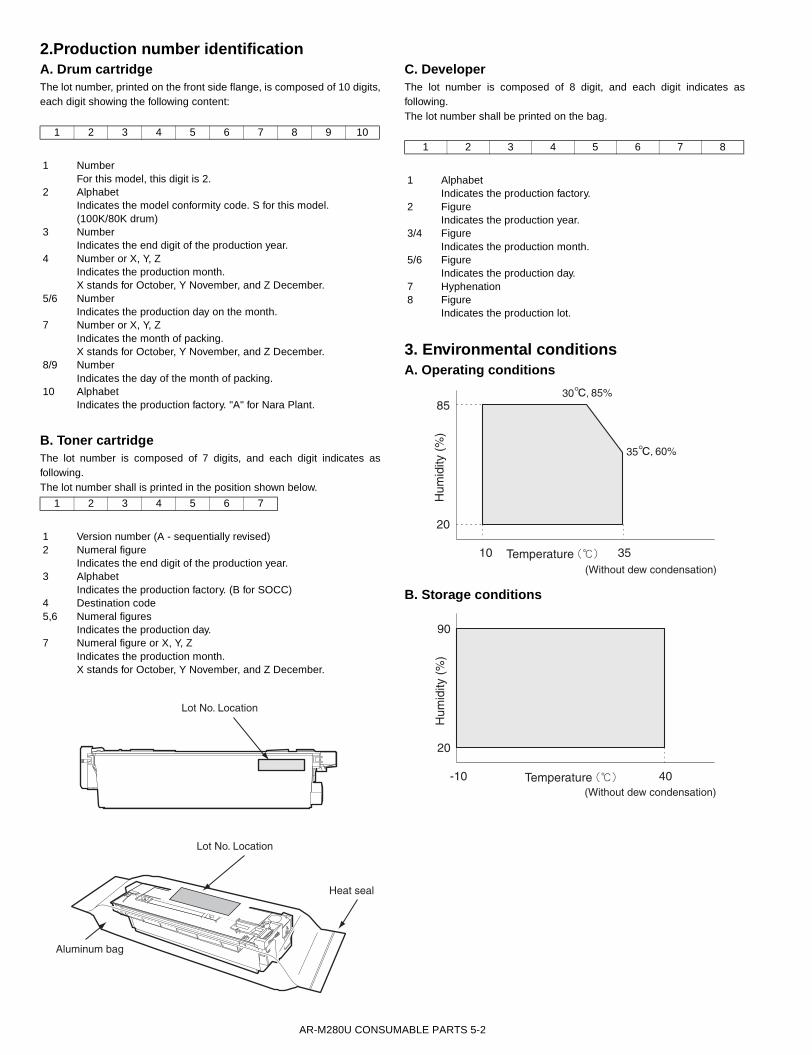
2.Production number identificationA. Drum cartridgeThe lot number, printed on the front side flange, is composed of 10 digits,each digit showing the following content:
B. Toner cartridgeThe lot number is composed of 7 digits, and each digit indicates asfollowing.The lot number shall is printed in the position shown below.
C. DeveloperThe lot number is composed of 8 digit, and each digit indicates asfollowing.The lot number shall be printed on the bag.
3. Environmental conditionsA. Operating conditions
B. Storage conditions
1 2 3 4 5 6 7 8 9 10
1 NumberFor this model, this digit is 2.
2 AlphabetIndicates the model conformity code. S for this model.(100K/80K drum)
3 NumberIndicates the end digit of the production year.
4 Number or X, Y, ZIndicates the production month.X stands for October, Y November, and Z December.
5/6 NumberIndicates the production day on the month.
7 Number or X, Y, ZIndicates the month of packing. X stands for October, Y November, and Z December.
8/9 NumberIndicates the day of the month of packing.
10 AlphabetIndicates the production factory. "A" for Nara Plant.
1 2 3 4 5 6 7
1 Version number (A - sequentially revised)2 Numeral figure
Indicates the end digit of the production year.3 Alphabet
Indicates the production factory. (B for SOCC)4 Destination code5,6 Numeral figures
Indicates the production day.7 Numeral figure or X, Y, Z
Indicates the production month.X stands for October, Y November, and Z December.
Lot No. Location
Lot No. Location
Aluminum bag
Heat seal
1 2 3 4 5 6 7 8
1 AlphabetIndicates the production factory.
2 FigureIndicates the production year.
3/4 FigureIndicates the production month.
5/6 FigureIndicates the production day.
7 Hyphenation8 Figure
Indicates the production lot.
Temperature
Hum
idity
(%
)
85
20
10 35(Without dew condensation)
30 85%
35 60%
Temperature
Hum
idity
(%
)
90
20
-10 40(Without dew condensation)
* "# $%&'()

AR-M280U CONSUMABLE PARTS 5-3
4.Different point of 50K drum and 80K drum
50K drum 80K drum1 Marking No mark on Flange White paint mark on rear side of Flange2 Lot number 2 digit : [ T ] 2 digit : [ S ]3 Flange assembly direction Painting upper limit : F side Painting upper limit : R side4 Color band on Drum Green Silver
White paint mark
100k (80k) drum
Silver
50k drum
Green
+ "# $%&'()
AR-M280U UNPACKING AND INSTALLATION 6-1
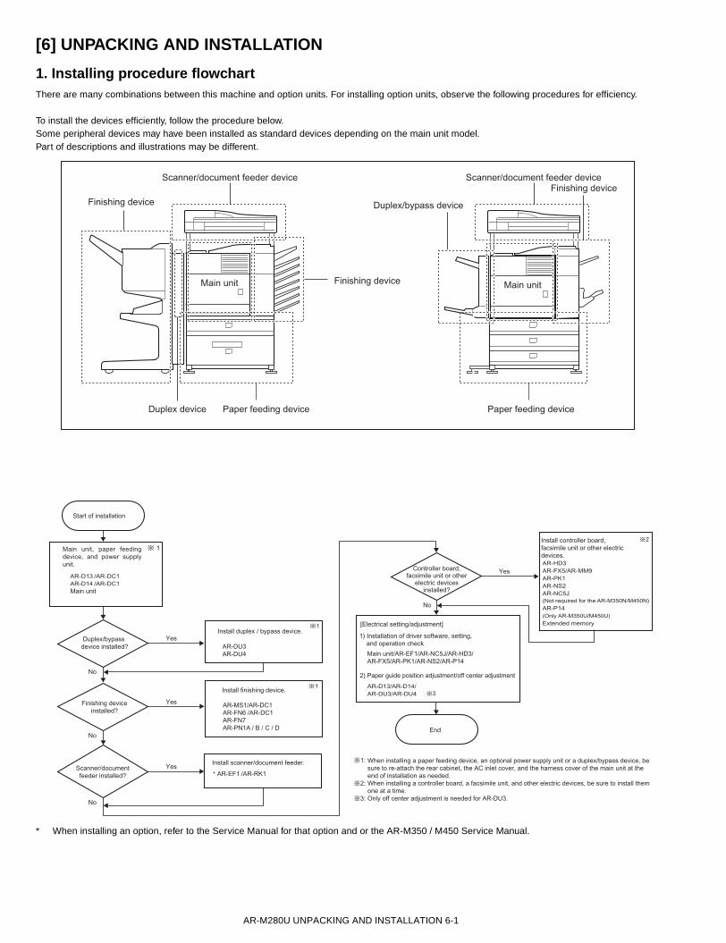
[6] UNPACKING AND INSTALLATION
1. Installing procedure flowchartThere are many combinations between this machine and option units. For installing option units, observe the following procedures for efficiency.
To install the devices efficiently, follow the procedure below.Some peripheral devices may have been installed as standard devices depending on the main unit model. Part of descriptions and illustrations may be different.
* When installing an option, refer to the Service Manual for that option and or the AR-M350 / M450 Service Manual.
Scanner/document feeder device
Main unit Main unitFinishing device
Finishing device
Duplex/bypass deviceFinishing device
Paper feeding deviceDuplex device Paper feeding device
Scanner/document feeder device
Start of installation
End
AR-D13 /AR-DC1AR-D14 /AR-DC1Main unit
* AR-EF1 /AR-RK1
AR-HD3AR-FX5/AR-MM9AR-PK1AR-NS2AR-NC5J(Not required for the AR-M350N/M450N)AR-P14(Only AR-M350U/M450U)Extended memory
AR-D13/AR-D14/AR-DU3/AR-DU4
AR-DU3AR-DU4
AR-MS1/AR-DC1AR-FN6 /AR-DC1AR-FN7AR-PN1A / B / C / D
No
Yes
Duplex/bypass device installed?
No
No
No
Finishing deviceinstalled?
Scanner/documentfeeder installed?
Yes
Yes
Yes
Controller board,facsimile unit or other
electric devicesinstalled?
When installing a paper feeding device, an optional power supply unit or a duplex/bypass device, be sure to re-attach the rear cabinet, the AC inlet cover, and the harness cover of the main unit at theend of installation as needed.When installing a controller board, a facsimile unit, and other electric devices, be sure to install themone at a time.Only off center adjustment is needed for AR-DU3.
Install controller board,facsimile unit or other electricdevices.
2) Paper guide position adjustment/off center adjustment
1) Installation of driver software, setting, and operation check
Main unit/AR-EF1/AR-NC5J/AR-HD3/AR-FX5/AR-PK1/AR-NS2/AR-P14
[Electrical setting/adjustment]
Main unit, paper feeding device, and power supply unit.
Install duplex / bypass device.
Install finishing device.
Install scanner/document feeder.
"# $%&'()

AR-M280U UNPACKING AND INSTALLATION 6-2
2. AR-P14 installing procedure<Before installation>
* This installation procedure is provided for use with theAR-M280U / M280N and AR-M350U / M450U series.
* To connect this machine to a network, a Print Server Card (NIC) AR-NC5J must be installed to the multi-function controller board inadvance.
* To enable the printer expansion function, the product key must beacquired.
The application number, machine serial number, and product keynumber are important information.Keep the above information for future reference.
1) Mount the printer expansion kit ROMs to the control PWB.<1>Turn off the main switch of the main unit of the printerTurn the main switch located on the front side of the main unit to the"OFF" position.If the machine is equipped with a facsimile unit, also turn off the FAXpower switch.Then remove the power plug from the outlet..
<2>Remove the cables connected to the control PWB unit.Remove all the cables connected to the control PWB unit of the main unitof the printer.
<3>Remove the control PWB unit.Remove the five screws that fix the control PWB unit to the main unit ofthe printer.Then, hold the two grips and pull out the control PWB unit to remove itfrom the main unit.
<4>Mount the printer expansion kit ROMs(2 pcs.)to the control PWB.Remove the ROMs(main and boot ROMs)from the control PWB andreplace them with the two ROMs(main and boot ROMs)of the printerexpansion kit.The main and boot ROMs are indicated with "MAIN" and "BOOT" on thelabels on the ROMs respectively.When mounting the printer expansion kit ROMs, insert them to the samepositions in the same direction as those before replacement and ensurethat the inserted printer expansion kit ROMs are locked with the fittingsof the sockets.
<5>Re-attach the control PWB.Attach the control PWB to the main unit of the printer and fix it using fivescrews.
"# $%&&'&(
AR-M280U UNPACKING AND INSTALLATION 6-3
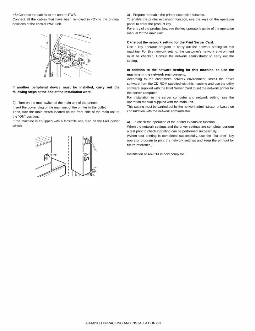
<6>Connect the cables to the control PWB.Connect all the cables that have been removed in <2> to the originalpositions of the control PWB unit.
If another peripheral device must be installed, carry out thefollowing steps at the end of the installation work.
2) Turn on the main switch of the main unit of the printer.Insert the power plug of the main unit of the printer to the outlet.Then, turn the main switch located on the front side of the main unit tothe "ON" position.If the machine is equipped with a facsimile unit, turn on the FAX powerswitch.
3) Prepare to enable the printer expansion function.To enable the printer expansion function, use the keys on the operationpanel to enter the product key.For entry of the product key, see the key operator's guide of the operationmanual for the main unit.
Carry out the network setting for the Print Server Card.Use a key operator program to carry out the network setting for thismachine. For this network setting, the customer's network environmentmust be checked. Consult the network administrator to carry out thesetting.
In addition to the network setting for this machine, to use themachine in the network environment:According to the customer's network environment, install the driversoftware from the CD-ROM supplied with this machine and use the utilitysoftware supplied with the Print Server Card to set the network printer forthe server computer.For installation in the server computer and network setting, see theoperation manual supplied with the main unit.This setting must be carried out by the network administrator or based onconsultation with the network administrator.
4) To check the operation of the printer expansion function.When the network settings and the driver settings are complete, performa test print to check if printing can be performed successfully.(When test printing is completed successfully, use the "list print" keyoperator program to print the network settings and keep the printout forfuture reference.)
Installation of AR-P14 is now complete.
+ "# $%&'()
AR-M280U MAINTENANCE 7-1
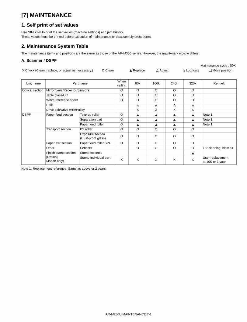
[7] MAINTENANCE
1. Self print of set valuesUse SIM 22-6 to print the set values (machine settings) and jam history.These values must be printed before execution of maintenance or disassembly procedures.
2. Maintenance System TableThe maintenance items and positions are the same as those of the AR-M350 series. However, the maintenance cycle differs.
A. Scanner / DSPFMaintenance cycle : 80K
Note 1: Replacement reference: Same as above or 2 years.
X Check (Clean, replace, or adjust as necessary.) O Clean Replace Adjust Lubricate Move position
Unit name Part nameWhen calling
80k 160k 240k 320k Remark
Optical section Mirror/Lens/Reflector/Sensors O O O O O
Table glass/OC O O O O O
White reference sheet O O O O O
Rails
Drive belt/Drive wire/Pulley X X X X
DSPF Paper feed section Take-up roller O Note 1
Separation pad O Note 1
Paper feed roller O Note 1
Transport section PS roller O O O O O
Exposure section (Dust-proof glass)
O O O O O
Paper exit section Paper feed roller SPF O O O O O
Other Sensors O O O O For cleaning, blow air.
Finish stamp section[Option](Japan only)
Stamp solenoid
Stamp individual partX X X X X
User replacement at 10K or 1 year.

AR-M280U MAINTENANCE 7-2
B. Engine section* For disassembly procedures, refer to the AR-P350/P450 Service Manual.
Maintenance cycle : 80K
Note 2: Replacement reference: Use the counter value of each paper feed port as the replacement reference.Paper feed roller/Torque limiter section: 80K or 2 years
O Check (Clean, replace, or adjust as necessary.) X Clean Replace Adjust Lubricate Move position
Unit name Part nameWhen calling
80k 160k 240k 320k Remark
Drum peripheral Drum Installed when shipping
Cleaner blade
Toner reception seal
Side molt
Transfer roller X
Discharge plate X
TR bearing (F/R) X X X
After-transfer star ring X X X
TR gear X X X
Screen grid (O)X
Drum separation pawl UN
Charger case (M/C) O O O O
Charging plate (saw teeth)
(O)X
Developing section Developer Supplied when installing
DV blade
DSD collar O O O O
DV side seal F
DV side seal R
Toner cartridge Attached when installing./EX Japan: 814g, user replacement for every 27K.
Fusing section Upper heat roller O O
Lower heat roller O O
Upper separation pawl X X
Lower separation pawl X X
Thermistor X X X X Clean and remove paper dust.
Upper heat roller gear X X
Paper guides O O O O O
Gears
Cleaning roller X X
CL roller collar
Filters Ozone filter
Paper feed section Paper feed roller O X X X X Note 2
Torque limiter X X X X X Note 2
Transport section Paper exit reverse section
PS follower roller O O O O O
Transport rollers O O O O O
Transport paper guides O O O O O
Paper dust remover
Drive section Gears (Specified position)
Belts X
Image quality X X X X X
Other Sensors X X X X
!
AR-M280U MAINTENANCE 7-3
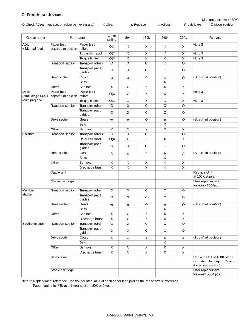
C. Peripheral devicesMaintenance cycle : 80K
Note 3: Replacement reference: Use the counter value of each paper feed port as the replacement referencePaper feed roller / Torque limiter section: 80K or 2 years
O Check (Clean, replace, or adjust as necessary.) X Clean Replace Adjust Lubricate Move position
Option name Part nameWhen calling
80k 160k 240k 320k Remark
ADU+ Manual feed
Paper feed separation section
Paper feed rollers
(O)X X X X XNote 3
Separation pad (O)X X X X X Note 3
Torque limiter (O)X X X X X Note 3
Transport section Transport rollers O O O O O
Transport paper guides
O O O O O
Drive section Gears (Specified position)
Belts X
Other Sensors X X X X X
Desk(Multi stage LCC)Multi purpose
Paper feed separation section
Paper feed rollers
(O)X X X X XNote 3
Torque limiter (O)X X X X X Note 3
Transport section Transport roller O O O O O
Transport paper guides
O O O O O
Drive section Gears (Specified position)
Belts X
Other Sensors X X X X X
Finisher Transport section Transport rollers O O O O O
De-curler roller (O)X X X X X
Transport paper guides
O O O O O
Drive section Gears (Specified position)
Belts X
Other Sensors X X X X X
Discharge brush X X X X X
Staple unit Replace Unit at 100K staple.
Staple cartridge User replacement for every 3000pcs.
Mail-binstacker
Transport section Transport roller O O O O O
Transport paper guides
O O O O O
Drive section Gears (Specified position)
Belts X
Other Sensors X X X X X
Discharge brush X X X X X
Saddle finisher Transport section Transport roller O O O O O
Transport paper guides
O O O O O
Drive section Gears (Specified position)
Belts X
Other Sensors X X X X X
Discharge brush X X X X X
Staple Unit Replace Unit at 100K staple (including the staple UN and the holder section).
Staple cartridge User replacement for every 5000 pcs.
"

AR-M280U ADJUSTMENTS 8-1
[8] ADJUSTMENTS1. Process section A. High voltage output adjustment
(1) Developing bias output check and setup1) Remove the rear cabinet to allow checking of the high voltage
monitor output pin. 2) Execute the simulation of the target high voltage.
(See the table below.)3) Select the mode to be set with 10-key, and press START key. 4) Enter the set value with 10-key and press START key. The set value
is outputted for 30 sec. 5) Apply a high voltage tester between the measurement pin and the
frame.Note:Take care not to short the measuring pin to the frame.
6) The unit stops after 30 sec of output.
2. Engine sectionA. Resist quantity setup
•This adjustment requires a high level of accuracy. We recommend using the default setting.
This adjustment is performed in the following cases:•When the void quantity is changed by the paper feed tray. •When paper is skewed.
Complete the following adjustments before performing resist quantitysetup. •LSU right angle adjustment•Print magnification ratio adjustment•Print off-center setup•Void area setup
1) Execute SIM 51-2.2) Adjust the resist quantity so that paper transport is stable.
<Factory setup value>
Default Set range Measurement pin
High voltage probe
impedanceMonitor output
voltageSet value
MC grid MAIN GRID(SIM 8-2)
AUTO AE mode -650V±5V 645 200~900 CN2-7 100MΩCHARACTER Text mode -650V±5V 645 200~900
MIX Text/Photo mode
-650V±5V 645 200~900
PHOTO Photo mode -650V±5V 645 200~900
PRINTER Printer mode -650V±5V 645 200~900
FAX Fax mode -650V±5V 645 200~900
Transfer current THV+(SIM 8-6)
FRONT Front 45PPM : 26728/35PPM : 220
0~620
BACK Back 45PPM : 31028/35PPM : 267
0~620
Developing bias DV BIAS(SIM 8-1)
AUTO AE mode -500V±5V 485 0~745 CN2-1 100MΩCHARACTER Text mode -500V±5V 485 0~745
MIX Text/Photo mode
-500V±5V 485 0~745
PHOTO Photo mode -500V±5V 485 0~745
PRINTER Printer mode -500V±5V 485 0~745
FAX Fax mode -500V±5V 485 0~745
PLUS Positive bias +150V±5V 150 0~255
Separation voltage SHV(SIM 8-17)
FRONT Front +1.25V±0.1V 45PPM : 16028/35PPM : 120
0~375 CN2-3 10MΩ
BACK Rear +1.25V±0.1V 45PPM : 16028/35PPM : 120
0~375
Transfer voltage THV(SIM 8-17)
-800V±10V 780 0~1250 CN2-5 10GΩ
45PPM BPT 55T1 60T2 50DESK 50ADU 50
28/35PPM BPT 60T1 65T2 55DESK 55ADU 55
!"#$%

AR-M280U SIMULATIONS 9-1
[9] SIMULATIONThe following simulations have been changed.
<List of display value>
<List of set values>
<List of set values>
Main code 8
8-6Purpose AdjustmentFunction (Content) Used to check and adjust the transfer charger
current and its control circuit. Section Process
(OPC drum, developing, transfer, cleaning)ItemOperation/Procedure Enter the output value to be adjusted with
10 digit key pad. The current set value is highlighted at the right of each item. After entering the value with 10 digit key pad, press START key. The output is made for 30sec at the set value. Then the output is stopped.
Default Set range
1 Cassette/manual paper feed 45PPM 267 0 ~ 620
28/35PPM 220
2 Paper feed from ADU 45PPM 310
28/35PPM 267
1
SIMULATION 8-6THV+SETTING. INPUT VALUE, AND PRESS START.1. FRONT(0-620) 140
SIMULATION 8-6THV+SETTING. EXECUTING...1. FRONT 140
SIMULATION 8-6THV+SETTING. SELECT 1-2, AND PRESS START.1. FRONT 1402. BACK 140
Or after 30sec output
Press [START] key. Press [CUSTOM SETTING] key.
Press [START] key. Press [CUSTOM SETTING] key.
8-17Purpose Operation test, checkFunction (Content) Used to set and check the transfer roller output. Section Process
(OPC drum, developing, transfer, cleaning)Item OperationOperation/Procedure Enter the output value to be adjusted with
10 digit key pad. The current set value is highlighted at the right of each item. After entering the value with 10 digit key pad, press START key. The output is made for 30sec at the set value. Then the output is stopped.
Default Set range
1 SHV front surface 160(45PPM)120(28/35PPM)
0 ~ 375
2 SHV back surface
3 THV-output 780 0 ~1250
Main code 21
21-1Purpose SetupFunction (Content) Used to set the maintenance cycle. SectionItem SpecOperation/Procedure Used to set the maintenance cycle in an SRU
machine.
0 Maintenance display at the cycle of each control spec.1 Maintenance display at 5K2 Maintenance display at 10K3 Maintenance display at 25K4 Maintenance display at 50K5 Maintenance display at 80K6 No maintenance display7 Maintenance display at 100K8 Maintenance display at 20K9 Maintenance display at 40K
1
SIMULATION 8-17TRANSFER ROLLER SETTING. INPUT VALUE, AND PRESS START.1. FRONT (0-375) 500
SIMULATION 8-17TRANSFER ROLLER SETTING. EXECUTING...1. FRONT (0-375) 500
SIMULATION 8-17TRANSFER ROLLER SETTING. SELECT 1-3, AND PRESS START.1. SHV FRONT 5002. SHV BACK 5003. THV- 500
Or after 30sec output
Press [START] key. Press [CUSTOM SETTING] key.
Press [START] key. Press [CUSTOM SETTING] key.
SIMULATION 21-1MAINTENANCE CYCLE SETUP. SELECT 0-6, AND PRESS START. 0. DEFAULT 1. 5K 2. 10K 3. 25K 4. 50K 5. 80K 6.FREE 7. 100K 8. 20K 9. 40K 1
!"#$%&

AR-M280U SIMULATIONS 9-2
<List of display values>
*1: Only when this value is 0, control is performed with the actual measurement value of process Thermistor. If it is not 0, control is forcibly performed.
*2: When the drum motor standby time is greater than this value, the correction of SIM 44-1 Vb1 is performed.
*3: This value is SIM 44-9 Vb1-1 correction value. The value corresponding to the drum rotating time is used.
*4: This value is SIM 44-9 Vb1-2 correction value. The value corresponding to the drum rotating time is used.
<List of display values>
*1: Vb1-1 and Vb1-2 are enabled or disabled by SIM 44-1 Vb1 setup.*2: When PTH is set to 0 with SIM 44-4, the detected value in this
adjustment is displayed. If PTH is set to other than 0, the value set with SIM 44-4 is displayed.
Main code 44
44-1Purpose SetupFunction (Content) Used to set Enable/Disable of each correction
operation in the image forming (process) section.
Section Process (OPC drum, developing, transfer, cleaning)
Item OperationOperation/Procedure
44-4Purpose SetupFunction (Content) Used to set the target image (reference) density
level in the developing bias voltage correction. Section Process
(OPC drum, developing, transfer, cleaning)Item DataOperation/Procedure The process correction value is set.
Select an item (1 - 9), and enter a value with 10 digit key pad. Press START to store the value.
1 PTH *1 Process Thermistor temperature forcible set value (0-99°C : Normal 0)
2 S_WT *2 Vb (Developing bias correction value) rising correction wait time (0-180sec : Default 90)
3 Vb1-1 *3 Vb (Developing bias correction value) correction quantity (First rotation) 1 (0 - 150V : Default 50)
4 Vb1-2 *3 Vb (Developing bias correction value) correction quantity (First rotation) 2 (0 - 150V : Default 50)
5 Vb1-3 *3 Vb (Developing bias correction value) correction quantity (First rotation) 3 (0 - 150V : Default 50)
6 Vb2-1 *4 Vb (Developing bias correction value) correction quantity (Second rotation) 1 (0 - 50V : Default 15)
7 Vb2-2 *4 Vb (Developing bias correction value) correction quantity (Second rotation) 2 (0 - 50V : Default 15)
8 Vb2-3 *4 Vb (Developing bias correction value) correction quantity (Second rotation) 3 (0 - 50V : Default 15)
SIMULATION 44-1PROCESS CORRECTION VALUE SETTING. INPUT VALUE 0-255AND PRESS START.BIT0:Vg1, BIT1:Vg2, BIT2:Vb1, BIT3:Vb2BIT4:Vb3, BIT5:LD1, BIT6:LD2BIT7:EX 255
015
014
013
012
011
010
0 0 EX9 8 7
LD26
LD15
Vb34
Vb23
Vb12
Vg21
Vg10Bit
bit = 1 : Correction enabled
1
SIMULATION 44-4PROCESS CONTROL VALUE SETTING. INPUT VALUE, AND PRESSSTART.1.PTH 45
SIMULATION 44-4PROCESS CONTROL VALUE SETTING. SELECT 1-8 AND PRESSSTART.1.PTH 00 2.S-WT 1003.Vb1-1 50 4.Vb1-2 50 5.Vb1-3 506.Vb2-1 50 7.Vb2-2 50 8.Vb2-3 50
Press [CUSTOM SETTING] key.Press [START] key.
DRUM ROTATION TIME Vb1 correction value(X’ th rotation)45PPM 35PPM 28PPM
0 ~ 40K (sec) 0 ~ 50K (sec) (X’ th rotation) -1
40 ~ 80K (sec) 50 ~ 95K (sec) (X’ th rotation) -2
80K ~ (sec) 95K ~ (sec) (X’ th rotation) -3
44-9Purpose Adjustment, setup, operation data output, check
(display)Function (Content) Used to check the result (main charger grid
voltage developing bias voltage, laser power, etc.) of correction (process correction) in the image forming section. (By this simulation, the correction operation can be checked.)
Section Process (OPC drum, developing, transfer, cleaning)
Item DataOperation/Procedure The process correction value is checked.
DRUM ROTATION TIME Drum rotation timeVg1~Vg2 Grid voltage correction valueVb1-1 *1 Vb (Developing bias correction value)
correction value (first rotation)Vb1-2 *1 Vb (Developing bias correction value)
correction value (second rotation)Vb2 Developing bias correction valueVb3 Developing bias correction valueLD1 Laser power correction valueLD2 Laser power correction valueCONTROL CRUM control spec (1 - 3)DESTINATION CRUM destination (A - L)PTH *2 Process Thermistor temperature valueT0 Toner control correction value
(Rotation time correction) (±100)T1 Toner control correction value T1
(Temperature correction) (±100)T2 Toner control correction value T2
(Temperature correction) (±100)
SIMULATION 44-9PROCESS CONTROL DATA DISPLAY.DRUM ROTATION TIME: 01234567 (sec)Vg1: 30 (V) Vg2: 30 (V)Vb1-1: 30 (V) Vb1-2: 30 (V) Vb2: 10 (V)LD1: 0.05 (mW) LD2: 0.05 (mW)CONTROL: 1 DESTINATION: A PTH: 30 (deg)TO: -5 T1: -5 T2: -3
' !"#$%&

AR-M280U SIMULATIONS 9-3
<List of set values 1>
<List of display values 1>
<List of set values 2>
* The selected tray is registered as an initial set value in the initialscreen.
<List of set values>
Main code 51
51-2Purpose AdjustmentFunction (Content) Used to adjust the contact pressure of paper on
the resist roller in each section (machine paper feed, duplex paper feed, SPF paper feed). (This adjustment is required when the print image position varies or when paper jam occurs frequently.)
Section Paper transport (paper exit, switchback, transport)
Item OperationOperation/Procedure Perform the resist quantity adjustment.
1) The current set value is highlighted on theright of each item. In this screen, be sure toselect "1: COPY START." (Set value: 1)
2) Enter the correction value with 10 digit keypad. Press P to store the set value.
3) When the value is increased by 1, the resistquantity is changed by 1ms.
4) Press START to start copying and store theset value. (Display value: 1)
5) Select a paper feed tray. (Set value 2)
SIMULATION 51-2RESIST TIMING ADJUSTMENT. SELECT 0-8, AND PRESS START.0. TRAY SELECT 1 1.PRINT START2. TRAY1 50 3. TRAY2 50 4. DESK 505. BPT 50 6. ADU 507. SPF(HIGH) 50 8. SPF(LOW) 50
1
SIMULATION 51-2RESIST TIMING ADJUSTMENT. INPUT VALUE 0-99, AND PRESSSTART.1. TRAY1
SIMULATION 51-2RESIST TIMING ADJUSTMENT. NOW PRINTING.
SIMULATION 51-2RESIST TIMING ADJUSTMENT. SELECT 1-15, AND PRESS START.(FEED TRAY)1. TRAY1 2. TRAY2 3. TRAY3 4. TRAY45. BPT(ABOVE +10: DUPLEX MODE)
Press [CUSTOM SETTING] key.Select 0 or 1, and press [START] key.
Select 1, and press [START] key.
Select 0, and press [START] key.
Press [START] key or
press [CUSTOM SETTING] key.
Press [CUSTOM SETTING] key.Or copying is terminated.
45PPM 28PPM35PPM
0 TRAY SELECT
Paper feed tray selection (1 - 5)
1 PRINT START
Copy start (Initial value)
2 TRAY1 Tray 1 resist adjustment value 60 65
3 TRAY2 Tray 2 resist adjustment value 50 55
4 DESK Desk resist adjustment value 50 55
5 BPT Manual tray resist adjustment value 55 60
6 ADU ADU resist adjustment value 50 55
7 SPF(HIGH) SPF resist adjustment value (High speed)
60 60
8 SPF(LOW) SPF resist adjustment value (Low speed)
75 75
Normal display NOW COPYINGERROR display Door open DOOR OPEN.
Jam JAMPaper empty PAPER EMPTY.
1 TRAY1 11 TRAY1 with Duplex2 TRAY2 12 TRAY2 with Duplex3 TRAY3 13 TRAY3 with Duplex4 TRAY4 14 TRAY4 with Duplex5 Manual feed 15 Manual feed with Duplex
Main code 61
61-2Purpose AdjustmentFunction (Content) Used to adjust the laser power (absolute value)
in the copy mode. Section PCUItem OperationOperation/Procedure Enter the laser power set value in copying,
and press START to store it.
Initial value Set range
1 Auto exposure mode 45PPM 100 100 - 150(45PPM)76 - 150(28/35PPM)
35/28PPM 76
2 Text mode 45PPM 100
35/28PPM 76
3 Text/Photo mode 45PPM 100
35/28PPM 76
4 Photo mode 45PPM 100
35/28PPM 76
SIMULATION 61-2LASER POWER SETTING (COPY). SELECT 1-4, AND PRESS START.1. AE 2. TEXT3. MIX 4. PHOTO 1
5
SIMULATION 61-2LASER POWER SETTING(COPY). INPUT VALUE 1-165, AND PRESS START.1. AE
5 555
Press [START] key. Press [CUSTOM SETTING] key or [START] key.
( !"#$%&

AR-M280U SIMULATIONS 9-4
<List of set values>
<List of set values>
Default setup for supporting 100K drums1) When the value is changed from 127 to 255 by SIM 44-1, the
following default values of the laser power setup must be adjusted.
* When the EEPROM is replaced (memory is cleared) in a 28-sheetmachine, setup of the 100K drum must be performed with SIM 44-1(setup value: 255).The above setup values are adjusted according to the setup of SIM44-1. (Though the destination setup is changed (SIM 26-6), theabove setup will not be changed automatically.)
61-3Purpose AdjustmentFunction (Content) Used to adjust the scanner (exposure) laser
power (absolute value) in the FAX reception mode. (Only when FAX is installed.)
Section PCUItem OperationOperation/Procedure Set the laser power in FAX reception.
Enter the set value and press Start to store it.
Initial value Set range
1 FAX reception 45PPM 100 100 - 150(45PPM)76 - 150(28/35PPM)
35/28PPM 76
61-4Purpose AdjustmentFunction (Content) Used to adjust the laser power (absolute value)
in the printer mode. Section PCUItemOperation/Procedure Set the laser power value in the printer mode.
Enter the value and press START to store it.
Initial value Set range
1 PRINTER 45PPM 100 100 - 150(45PPM)76 - 150(28/35PPM)
28/35PPM 76
SIMULATION 61-3LASER POWER SETTING (FAX). PRESS START.1. FAX 1
5
SIMULATION 61-3LASER POWER SETTING (FAX). INPUT VALUE 1-165, AND PRESS START.1. FAX
5
Press [START] key. Press [CUSTOM SETTING] key or [START] key.
SIMULATION 61-4LASER POWER SETTING (PRINTER). PRESS START.1. PRINTER 1
5
SIMULATION 61-4LASER POWER SETTING (PRINTER). INPUT VALUE 1-165, AND PRESS START.1. PRINTER
5
Press [START] key. Press [CUSTOM SETTING] key or [START] key.
Drum 50K 100K(80K)
Sim44-1 127 255
Model 35PPM 45PPM 35PPM 45PPM 28PPM
Laser powersetupSIM 61-2
80 104 76 100 76
Maintenance cycleSIM 21-1
0(50K) 7(100K) 5(80K)
) !"#$%&

q PARTS GUIDE
CONTENTS
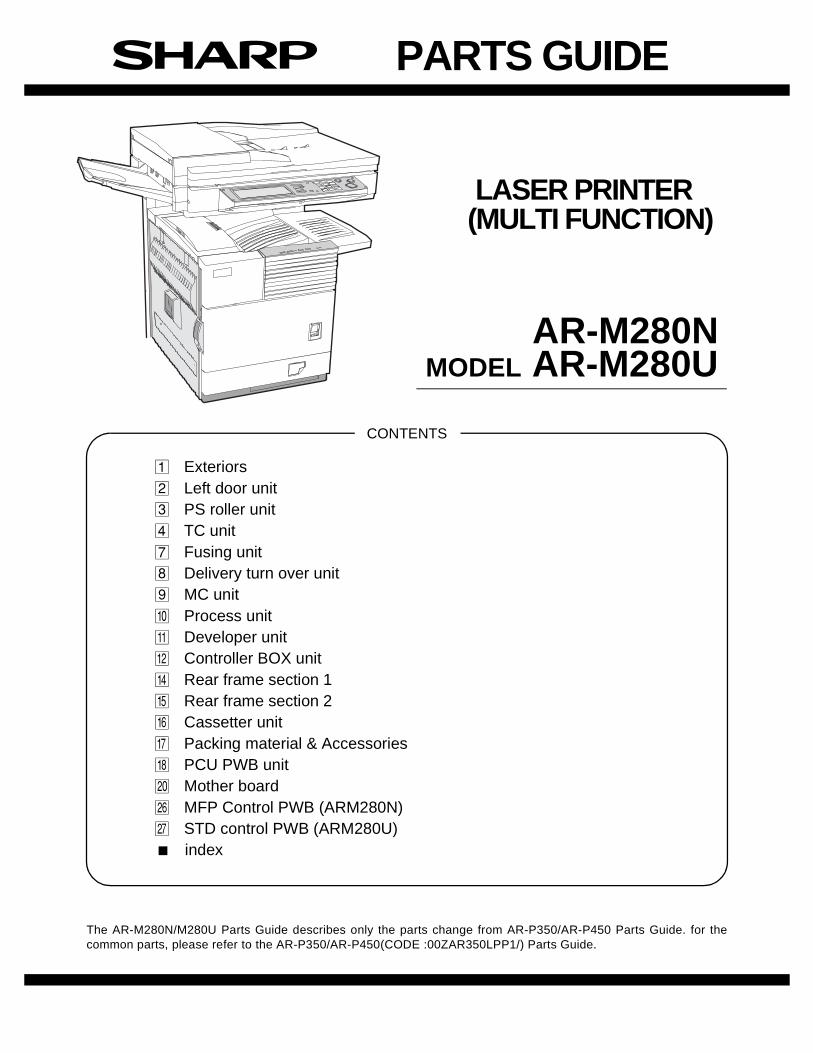
The AR-M280N/M280U Parts Guide describes only the parts change from AR-P350/AR-P450 Parts Guide. for thecommon parts, please refer to the AR-P350/AR-P450(CODE :00ZAR350LPP1/) Parts Guide.
LASER PRINTER (MULTI FUNCTION)
AR-M280N MODEL AR-M280U
1 Exteriors2 Left door unit3 PS roller unit4 TC unit7 Fusing unit8 Delivery turn over unit9 MC unitF Process unitG Developer unitH Controller BOX unitJ Rear frame section 1K Rear frame section 2L Cassetter unitM Packing material & AccessoriesN PCU PWB unitP Mother boardV MFP Control PWB (ARM280N)W STD control PWB (ARM280U) index

– 1 –
DEFINITIONThe definition of each Rank is as follows and also noted in the list
A: Parts necessary to be stocked as High usage parts.B: Parts necessary to be stocked as Standard usage parts.C: Low usage parts.D: Parts necessary for refurbish.E: Unit parts recommended to be stocked for efficient after sales service.
Please note that the lead time for the said parts may be longer than normal parts.S: Consumable parts.Please note that the following parts used in Copier under the same description are classified into A or B Rank depending uponthe place used.Example : Gear made of Metal, Sprocket, Bearing, Belt made of Rubber, Spring clutch mechanism.ARank : The parts which may be with the revolution or loading.BRank : Parts similar to A Rank parts, but are not included in Rank A.
Because parts marked with "!" is indispensable for the machine safety maintenance and operation, it must be replaced withthe parts specific to the product specification.
F Other than this Parts Guide, please refer to documents Service Manual(including Circuit Diagram)of this model.F Please use the 13 digit code described in the right hand corner of front cover of the document, when you place an order.F For U.S. only-Use order codes provided in advertising literature. Do not order from parts department.
1 Exteriors
2 Left door unit
3 PS roller unit
4 Main drive unit
7 Fusing unit
NO. PARTS CODE PRICERANK
NEWMARK
PARTRANK DESCRIPTION
5 GCAB-0940FCZ2 BA D Paper exit tray exterior11 HPNLC0243FCZ1 AP D Operation cabinet
26CPNLH0020QS41 AK N D Model panel [ARM280U]CPNLH0020QS42 AK N D Model panel [ARM280N]
NO. PARTS CODE PRICERANK
NEWMARK
PARTRANK DESCRIPTION
3 LX-BZ0147FCZ1 AC C Screw9 PTME-0287FCZ1 AD C Transfer lock pawl
13 LANGT1407FCZ2 AR C ACC fixing angle F16 PTME-0279FCZ1 AB C Left door lock pawl27 NFANP0069FCZZ AV B Fan
NO. PARTS CODE PRICERANK
NEWMARK
PARTRANK DESCRIPTION
11 PSHEP4925FCZZ AC C Paper powder remove sub sheet38 LX-BZ0589FCZZ AA C Screw
NO. PARTS CODE PRICERANK
NEWMARK
PARTRANK DESCRIPTION
25 LX-BZ0670FCZ1 AC C Screw67 LX-BZ0788FCZ1 AC C Screw71 NSFTZ2576FCZ1 AL C PS roller shaft
NO. PARTS CODE PRICERANK
NEWMARK
PARTRANK DESCRIPTION
3 PTME-0282FCZ1 AH C Upper separator pawl11 PCOVP1546FCZ1 AY C Fusing upper cover

– 2 –
8 Delivery turn over unit
8 Delivery turn over unit
9 MC unit
F Process unit
F Process unit
NO. PARTS CODE PRICERANK
NEWMARK
PARTRANK DESCRIPTION
5 NFANP0069FCZZ AV B Fan10 PGIDM1896FCZ1 AV C Paper exit upper PG14 LDAIU0626FCZ2 AK C Paper exit follower roller fixing plate38 NBLTH0327FCZ1 AL C Belt47 NBLTH0350FCZ1 AH C Belt62 PBRSS0208FCZ1 AH C Discharge brush66 PSHEP4962FCZ1 AC C Belt holder sheet
NO. PARTS CODE PRICERANK
NEWMARK
PARTRANK DESCRIPTION
3 CPLTM6048DS51 AL E Plate
NO. PARTS CODE PRICERANK
NEWMARK
PARTRANK DESCRIPTION
8 PMLT-1245FCZ2 AE C Process U cushion16 MSPRC3010FCZ1 AB C Shutter open close spring24 XBBSD30P08000 AA C Screw(3×8)26 LX-BZ0656FCZ1 AE C Screw45 PRNGF0106FCZ2 AC C Starling N47 MSPRC2954FCZ2 AB C Sparation pawl spring48 PMLT-1238FCZ1 AC C Toner shield cushion57 LX-WZ0440FCZZ AC C Spacer59 PSPAZ1431FCZZ AA C Spacer A60 PSPAZ1432FCZZ AA C Spacer B
501 CHLDZ1473DS51 BH E Separation pawl holder unit
FCP05237
66
57
59
60
FCP05238

– 3 –
G Developer unit
G Developer unit
H Controller BOX unit
H Controller BOX unit
NO. PARTS CODE PRICERANK
NEWMARK
PARTRANK DESCRIPTION
29 LPLTM6022FCZZ AC C M4 plate48 PMLT-1241FCZ1 AA C DV-BOX cushion49 PMLT-1244FCZ1 AC C Docter cushion R56 PMLT-1296FCZZ AH C Shutter cushion
NO. PARTS CODE PRICERANK
NEWMARK
PARTRANK DESCRIPTION
1 PDUC-0165FCZ1 AF C Controller duct5 NFANP0069FCZZ AV B Fan9 PCOVP1555FCZ1 AE C Controller BOX cover
12 NFANP0069FCZZ AV B Fan14 QCNW-0201FCZZ AG C Printer interface FFC21 DUNT-7093DS15 CD N E LSU 28 unit25 LX-BZ0921FCZ1 AE C Screw(3×6)26 XBPSD26P06000 AA C Screw(2.6×6)35 LPLTM5765FCZ1 AH C Control joint plate37 PCOVP1560FCZZ AC C FAX I/F cover38 PCOVP1557FCZZ AC C LAN/Option cover45 PSHEP4945FCZZ AC C Controller duct sheet B47 XBPSD30P06000 AA C Screw(3×6)50 XHBSE30P06000 AA C Screw(3×6)51 XBBSD30P06000 AA C Screw(3×6)
54VHI28F322L03F BR B MFP flash ROM A(28F322L03F)VHI28F322L15F BU B STD flash ROM A(28F322L15F)
55VHI28F322L04F BR B MFP flash ROM B(28F322L04F)VHI28F322L16F BU B STD flash ROM B(28F322L16F)
56 LX-BZ0828FCZZ AD C Screw57 PSHEP5009FCZZ AC C Control duct sheet
56
FCP05239
47
26
255026
47
51
51
FCP05240
45
5745
21
35
38
47
50
54
37 38
5156
51
51 5655
51
51
51
51
– 4 –
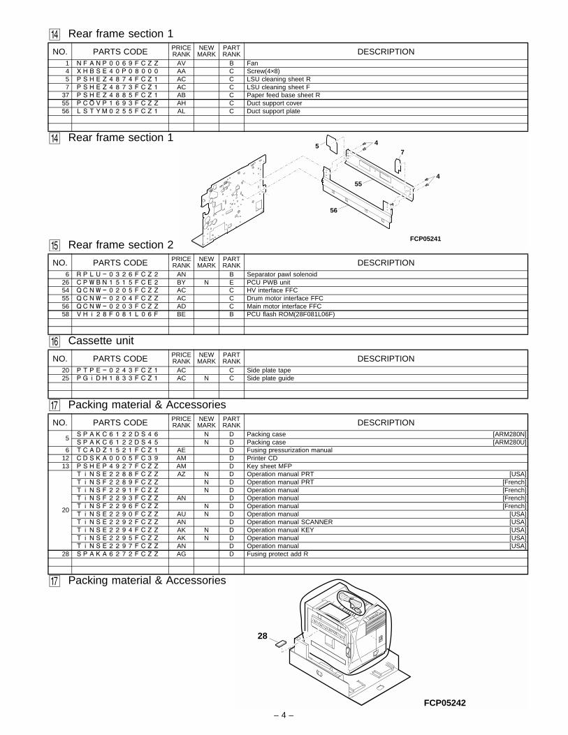
J Rear frame section 1
J Rear frame section 1
K Rear frame section 2
L Cassette unit
M Packing material & Accessories
M Packing material & Accessories
NO. PARTS CODE PRICERANK
NEWMARK
PARTRANK DESCRIPTION
1 NFANP0069FCZZ AV B Fan4 XHBSE40P08000 AA C Screw(4×8)5 PSHEZ4874FCZ1 AC C LSU cleaning sheet R7 PSHEZ4873FCZ1 AC C LSU cleaning sheet F
37 PSHEZ4885FCZ1 AB C Paper feed base sheet R55 PCOVP1693FCZZ AH C Duct support cover56 LSTYM0255FCZ1 AL C Duct support plate
NO. PARTS CODE PRICERANK
NEWMARK
PARTRANK DESCRIPTION
6 RPLU-0326FCZ2 AN B Separator pawl solenoid26 CPWBN1515FCE2 BY N E PCU PWB unit54 QCNW-0205FCZZ AC C HV interface FFC55 QCNW-0204FCZZ AC C Drum motor interface FFC56 QCNW-0203FCZZ AD C Main motor interface FFC58 VHI28F081L06F BE B PCU flash ROM(28F081L06F)
NO. PARTS CODE PRICERANK
NEWMARK
PARTRANK DESCRIPTION
20 PTPE-0243FCZ1 AC C Side plate tape25 PGIDH1833FCZ1 AC N C Side plate guide
NO. PARTS CODE PRICERANK
NEWMARK
PARTRANK DESCRIPTION
5SPAKC6122DS46 N D Packing case [ARM280N]SPAKC6122DS45 N D Packing case [ARM280U]
6 TCADZ1521FCZ1 AE D Fusing pressurization manual12 CDSKA0005FC39 AM D Printer CD13 PSHEP4927FCZZ AM D Key sheet MFP
20
TINSE2288FCZZ AZ N D Operation manual PRT [USA]TINSF2289FCZZ N D Operation manual PRT [French]TINSF2291FCZZ N D Operation manual [French]TINSF2293FCZZ AN D Operation manual [French]TINSF2296FCZZ N D Operation manual [French]TINSE2290FCZZ AU N D Operation manual [USA]TINSE2292FCZZ AN D Operation manual SCANNER [USA]TINSE2294FCZZ AK N D Operation manual KEY [USA]TINSE2295FCZZ AK N D Operation manual [USA]TINSE2297FCZZ AN D Operation manual [USA]
28 SPAKA6272FCZZ AG D Fusing protect add R
FCP05241
7
55
4
4
56
5
FCP05242
28

– 5 –
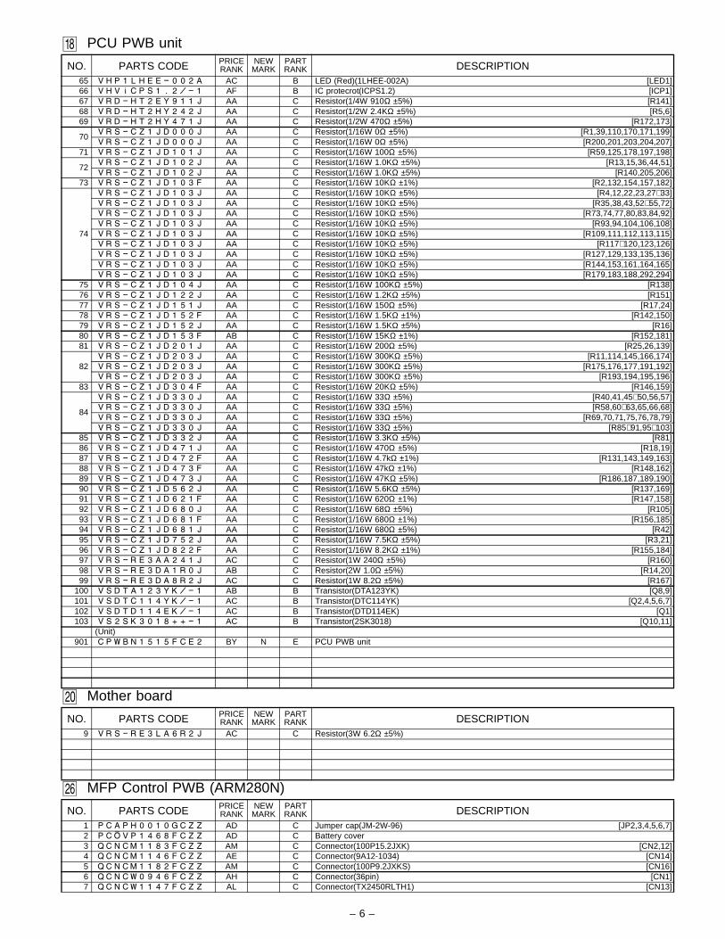
N PCU PWB unit
NO. PARTS CODE PRICERANK
NEWMARK
PARTRANK DESCRIPTION
1 QCNCM0670FCZZ AC C Connector(5pin) [CN17]2 QCNCM0878FCZZ AF C Connector(30pin) [CN12]3 QCNCM0923FC24 AF C Connector(24pin) [CN13]4 QCNCM0923FC32 AG C Connector(32Pin) [CN4]5 QCNCM1069ACZZ AD C Connector(6pin) [CN18]6 QCNCM1143FCZZ AG C Connector(22pin) [CN11]7 QCNCM1144FCZZ AH C Connector(24pin) [CN10]8 QCNCM1175FCZZ AG C Connector(30pin) [CN16]9 QCNCM5093SC0B AB C Connector(2pin) [CN7,22]
10 QCNCM7014SC0H AB C Connector(8pin) [CN5]11 QCNCM7014SC1A AC C Connector(11pin) [CN8]12 QCNCM7014SC1D AC C Connector(14pin) [CN14]13 QCNCW0002ESZZ AC C Connector(8pin) [CN9]14 QCNCW1136FCZZ AC C Connector(8pin) [CN6]15 QCNCW1139FCZZ AC C Connector(14pin) [CN15]16 QCNCW1140FCZZ AD C Connector(28pin) [CN1,2]17 QCNCW1150FCZZ AE C Connector(24pin) [CN3]18 QSOCZ0002QSZZ AD C IC socket(8pin) [IC17]19 QSOCZ0071FCZZ AP C Socket(MM20-72B1-1) [SOCKET1]20 QSW-P0005QSZZ AC B Tact switch(B3F-6102) [SW1]21 RCRSZ0001QSZZ AG B Crystal(19.6608MHz) [X1]22 RCRUB0002FCZZ AP B Crystal(31.554MHz) [X2]23 RFILN0042FCZZ AC C EMI filter(ZJSR5101-101) [NF1∼ 11]24 RFILN0047FCZZ AC C EMI filter(MMZ1608S121) [NF12,13]25 RMPTR4103ACZZ AB B Block resistor(10KΩ×4) [BR1∼ BR24]26 VCCCCZ1HH100D AA C Capacitor(50WV 10pF) [C86]27 VCCCCZ1HH101J AA C Capacitor(50WV 100pF) [C12,13,28,43]28 VCCCCZ1HH220J AA C Capacitor(50WV 22pF) [C39,50]29 VCEAGA0JW107M AC C Capacitor(6.3WV 100µF) [C146]30 VCEAGU1AW476M AA C Capacitor(10WV 47µF) [C17]31 VCEAGA1AW477M AB C Capacitor(10WV 470µF) [C99]32 VCEAGA1CW477M AB C Capacitor(16WV 470µF) [C108,147]33 VCEAGU1HW335M AA C Capacitor(50WV 3.3µF) [C63]34 VCEAGA1VW106M AA C Capacitor(35WV 10µF) [C2,104]35 VCEAGU1VW107M AB C Capacitor(35WV 100µF) [C117,118]36 VCEAGA1VW227M AB C Capacitor(35WV 220µF) [C129]37 VCEAGU1VW476M AB C Capacitor(35WV 47µF) [C9,144]
38
VCKYCZ1CF104Z AB C Capacitor(16WV 0.10µF) [C6,19,29,30,32,40,42,47]VCKYCZ1CF104Z AB C Capacitor(16WV 0.10µF) [C51,55,58,59,61,75,80]VCKYCZ1CF104Z AB C Capacitor(16WV 0.10µF) [C87,88,101,102,106,116]VCKYCZ1CF104Z AB C Capacitor(16WV 0.10µF) [C120,121,131,132,138]VCKYCZ1CF104Z AB C Capacitor(16WV 0.10µF) [C140,142,143,151,153]VCKYCZ1CF104Z AB C Capacitor(16WV 0.10µF) [C189,190,191]
39VCKYCZ1EF223Z AA C Capacitor(50WV 0.022µF) [C14,62,100,107,123]VCKYCZ1EF223Z AA C Capacitor(50WV 0.022µF) [C124,128,130,145]
40
VCKYCZ1HB102K AA C Capacitor(50WV 1000pF) [C1,5,15,16,18,31,33,34]VCKYCZ1HB102K AA C Capacitor(50WV 1000pF) [C36,37,41,44,46,48,49,52]VCKYCZ1HB102K AA C Capacitor(50WV 1000pF) [C53,54,57,60,64∼ 74]VCKYCZ1HB102K AA C Capacitor(50WV 1000pF) [C76,77,78,81,82∼ 85]VCKYCZ1HB102K AA C Capacitor(50WV 1000pF) [C89,90,91,93,94,96,97,98]VCKYCZ1HB102K AA C Capacitor(50WV 1000pF) [C103,105,109∼ 115,119]VCKYCZ1HB102K AA C Capacitor(50WV 1000pF) [C125,126,127,133,136,137]VCKYCZ1HB102K AA C Capacitor(50WV 1000pF) [C139,141,149,155,156,160]VCKYCZ1HB102K AA C Capacitor(50WV 1000pF) [C173∼ 188,148,154]
41 VCKYCZ1HB222K AA C Capacitor(50WV 2200pF) [C3,7,8,11]42 VCQYNU1HM103K AA C Capacitor(50WV 0.010µF) [C150]
43VHDDAN202K/-1 AB B Diode(DAN202K) [D1,8,9,11,13,16]VHDDAN202K/-1 AB B Diode(DAN202K) [D18,23,29,32]
44 VHDDAP202K/-1 AB B Diode(DAP202K) [D10,14,15,17,30]45 VHDDA204K//-1 AC B Diode(DA204K) [D2,3,12,19,20,31]46 VHDDSS133//-1 AA B Diode(1SS133) [D25,26,27]47 VHDMA704A//-1 AC B Diode(MA704A) [D22,28]48 VHDM1FL20U+-1 AC B Diode(M1FL20U) [D4,5,6,7,33]49 VHEHZS3B3//-1 AB B Zener diode(HZS3B3) [ZD1]50 VHERD22FB//-1 AD B Zener diode(RD22FB)(20.8-23.3V) [ZD2,3]51 VHID82805GN-1 BA B IC(D82805GN) [IC16]52 VHIEES04L400P AG B IC(EES04L400P) [IC17]53 VHIFS781BZB-1 AP B IC(FS781BZB) [IC13]
54VHIFS781BZB-1 AP B IC(FS781BZB) [IC13]VHIH8S2322R-1 AZ B IC(H8S2322R) [IC8]
55 VHILM324D++-1 AE B IC(LM324D) [IC22]56 VHILM339D++-1 AE B IC(LM339D) [IC18,21]57 VHILVX240SJ-1 AG B IC(LVX240SJ) [IC6]58 VHIMTD13611-1 AR B IC(MTD1361-4101) [IC3]59 VHINJM7805A-1 AH B IC(NJM7805A) [IC25]60 VHITA7291S/-1 AF B IC(TA7291S) [IC2,15]61 VHITD62003AP1 AG B IC(TD620003AP1) [IC1,19,20]62 VHITD62503F/- AG B IC(TD62503F) [IC7,12,14,23,24,26]63 VHI74VHCT240X AF B IC(74VHCT240X) [IC9]64 VHI74VHCT244X AF B IC(74VHCT244X) [IC4,5,10]
– 6 –
N PCU PWB unit
P Mother board
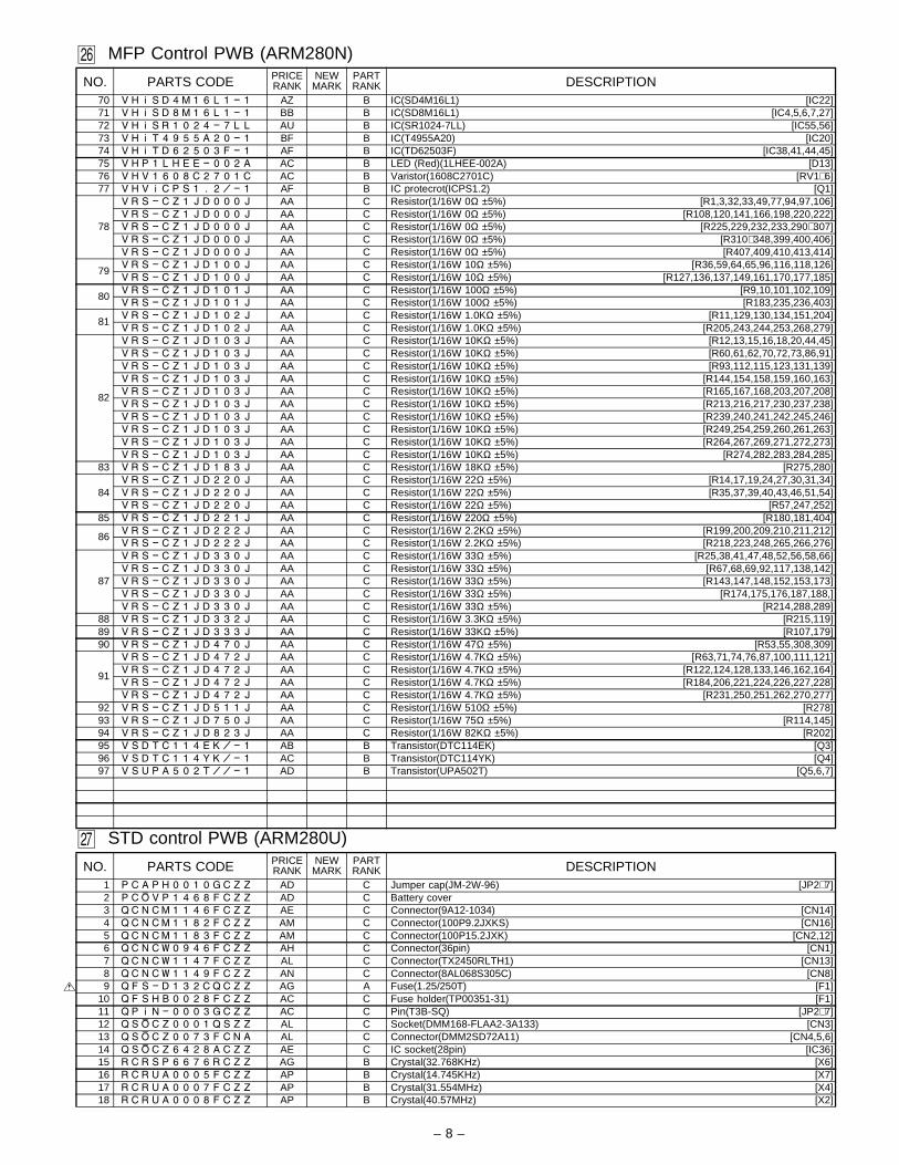
V MFP Control PWB (ARM280N)
NO. PARTS CODE PRICERANK
NEWMARK
PARTRANK DESCRIPTION
65 VHP1LHEE-002A AC B LED (Red)(1LHEE-002A) [LED1]66 VHVICPS1.2/-1 AF B IC protecrot(ICPS1.2) [ICP1]67 VRD-HT2EY911J AA C Resistor(1/4W 910Ω ±5%) [R141]68 VRD-HT2HY242J AA C Resistor(1/2W 2.4KΩ ±5%) [R5,6]69 VRD-HT2HY471J AA C Resistor(1/2W 470Ω ±5%) [R172,173]
70VRS-CZ1JD000J AA C Resistor(1/16W 0Ω ±5%) [R1,39,110,170,171,199]VRS-CZ1JD000J AA C Resistor(1/16W 0Ω ±5%) [R200,201,203,204,207]
71 VRS-CZ1JD101J AA C Resistor(1/16W 100Ω ±5%) [R59,125,178,197,198]
72VRS-CZ1JD102J AA C Resistor(1/16W 1.0KΩ ±5%) [R13,15,36,44,51]VRS-CZ1JD102J AA C Resistor(1/16W 1.0KΩ ±5%) [R140,205,206]
73 VRS-CZ1JD103F AA C Resistor(1/16W 10KΩ ±1%) [R2,132,154,157,182]
74
VRS-CZ1JD103J AA C Resistor(1/16W 10KΩ ±5%) [R4,12,22,23,27∼ 33]VRS-CZ1JD103J AA C Resistor(1/16W 10KΩ ±5%) [R35,38,43,52∼ 55,72]VRS-CZ1JD103J AA C Resistor(1/16W 10KΩ ±5%) [R73,74,77,80,83,84,92]VRS-CZ1JD103J AA C Resistor(1/16W 10KΩ ±5%) [R93,94,104,106,108]VRS-CZ1JD103J AA C Resistor(1/16W 10KΩ ±5%) [R109,111,112,113,115]VRS-CZ1JD103J AA C Resistor(1/16W 10KΩ ±5%) [R117∼ 120,123,126]VRS-CZ1JD103J AA C Resistor(1/16W 10KΩ ±5%) [R127,129,133,135,136]VRS-CZ1JD103J AA C Resistor(1/16W 10KΩ ±5%) [R144,153,161,164,165]VRS-CZ1JD103J AA C Resistor(1/16W 10KΩ ±5%) [R179,183,188,292,294]
75 VRS-CZ1JD104J AA C Resistor(1/16W 100KΩ ±5%) [R138]76 VRS-CZ1JD122J AA C Resistor(1/16W 1.2KΩ ±5%) [R151]77 VRS-CZ1JD151J AA C Resistor(1/16W 150Ω ±5%) [R17,24]78 VRS-CZ1JD152F AA C Resistor(1/16W 1.5KΩ ±1%) [R142,150]79 VRS-CZ1JD152J AA C Resistor(1/16W 1.5KΩ ±5%) [R16]80 VRS-CZ1JD153F AB C Resistor(1/16W 15KΩ ±1%) [R152,181]81 VRS-CZ1JD201J AA C Resistor(1/16W 200Ω ±5%) [R25,26,139]
82VRS-CZ1JD203J AA C Resistor(1/16W 300KΩ ±5%) [R11,114,145,166,174]VRS-CZ1JD203J AA C Resistor(1/16W 300KΩ ±5%) [R175,176,177,191,192]VRS-CZ1JD203J AA C Resistor(1/16W 300KΩ ±5%) [R193,194,195,196]
83 VRS-CZ1JD304F AA C Resistor(1/16W 20KΩ ±5%) [R146,159]
84
VRS-CZ1JD330J AA C Resistor(1/16W 33Ω ±5%) [R40,41,45∼ 50,56,57]VRS-CZ1JD330J AA C Resistor(1/16W 33Ω ±5%) [R58,60∼ 63,65,66,68]VRS-CZ1JD330J AA C Resistor(1/16W 33Ω ±5%) [R69,70,71,75,76,78,79]VRS-CZ1JD330J AA C Resistor(1/16W 33Ω ±5%) [R85∼ 91,95∼ 103]
85 VRS-CZ1JD332J AA C Resistor(1/16W 3.3KΩ ±5%) [R81]86 VRS-CZ1JD471J AA C Resistor(1/16W 470Ω ±5%) [R18,19]87 VRS-CZ1JD472F AA C Resistor(1/16W 4.7kΩ ±1%) [R131,143,149,163]88 VRS-CZ1JD473F AA C Resistor(1/16W 47kΩ ±1%) [R148,162]89 VRS-CZ1JD473J AA C Resistor(1/16W 47KΩ ±5%) [R186,187,189,190]90 VRS-CZ1JD562J AA C Resistor(1/16W 5.6KΩ ±5%) [R137,169]91 VRS-CZ1JD621F AA C Resistor(1/16W 620Ω ±1%) [R147,158]92 VRS-CZ1JD680J AA C Resistor(1/16W 68Ω ±5%) [R105]93 VRS-CZ1JD681F AA C Resistor(1/16W 680Ω ±1%) [R156,185]94 VRS-CZ1JD681J AA C Resistor(1/16W 680Ω ±5%) [R42]95 VRS-CZ1JD752J AA C Resistor(1/16W 7.5KΩ ±5%) [R3,21]96 VRS-CZ1JD822F AA C Resistor(1/16W 8.2KΩ ±1%) [R155,184]97 VRS-RE3AA241J AC C Resistor(1W 240Ω ±5%) [R160]98 VRS-RE3DA1R0J AB C Resistor(2W 1.0Ω ±5%) [R14,20]99 VRS-RE3DA8R2J AC C Resistor(1W 8.2Ω ±5%) [R167]
100 VSDTA123YK/-1 AB B Transistor(DTA123YK) [Q8,9]101 VSDTC114YK/-1 AC B Transistor(DTC114YK) [Q2,4,5,6,7]102 VSDTD114EK/-1 AC B Transistor(DTD114EK) [Q1]103 VS2SK3018++-1 AC B Transistor(2SK3018) [Q10,11]
(Unit)901 CPWBN1515FCE2 BY N E PCU PWB unit
NO. PARTS CODE PRICERANK
NEWMARK
PARTRANK DESCRIPTION
9 VRS-RE3LA6R2J AC C Resistor(3W 6.2Ω ±5%)
NO. PARTS CODE PRICERANK
NEWMARK
PARTRANK DESCRIPTION
1 PCAPH0010GCZZ AD C Jumper cap(JM-2W-96) [JP2,3,4,5,6,7]2 PCOVP1468FCZZ AD C Battery cover3 QCNCM1183FCZZ AM C Connector(100P15.2JXK) [CN2,12]4 QCNCM1146FCZZ AE C Connector(9A12-1034) [CN14]5 QCNCM1182FCZZ AM C Connector(100P9.2JXKS) [CN16]6 QCNCW0946FCZZ AH C Connector(36pin) [CN1]7 QCNCW1147FCZZ AL C Connector(TX2450RLTH1) [CN13]

– 7 –
V MFP Control PWB (ARM280N)
NO. PARTS CODE PRICERANK
NEWMARK
PARTRANK DESCRIPTION
8 QCNCW1149FCZZ AN C Connector(8AL068S305C) [CN8]! 9 QFS-D132CQCZZ AG A Fuse(1.25/250T) [F1]
10 QFSHB0028FCZZ AC C Fuse holder(TP00351-31) [F1]11 QPIN-0003GCZZ AC C Pin(T3B-SQ) [JP2,3,4,5,6,7,]12 QSOCZ0001QSZZ AL C Socket(DMM168-FLAA2-3A133) [CN3]13 QSOCZ0073FCNA AL C Connector(DMM2SD72A11) [CN4,5,6]14 QSOCZ6428ACZZ AE C IC socket(28pin) [IC36]15 RCRSP6676RCZZ AG B Crystal(32.768KHz) [X6]16 RCRUA0005FCZZ AP B Crystal(14.745KHz) [X7]17 RCRUA0007FCZZ AP B Crystal(31.554MHz) [X4]18 RCRUA0008FCZZ AP B Crystal(40.57MHz) [X2]19 RCRUA0009FCZZ AP B Crystal(66.666MHZ) [X3]20 RCRUA0012FCZZ AP B Crystal(66.666MHz)Åi5VLLLÅj [X1]21 RCRUA0014FCZZ AP B Crystal(68.5MHz) [X5]22 RFILN0048FCZZ AC C Ferrite bead(BLM10B121SB) [L2,3]23 RFILN0051FCZZ AC C Ferrite bead(MMZ1608D121B) [L25∼ 30,33,34]
24RMPTR4100ACZZ AB B Block resistor(10Ω×4) [BR6∼ 13,15∼ 25,28,29]RMPTR4100ACZZ AB B Block resistor(10Ω×4) [BR33∼ 44,46,48,53∼ 72]
25RMPTR4103ACZZ AB B Block resistor(10KΩ×4) [BR1∼ 5,14,26,27,30,31,32]RMPTR4103ACZZ AB B Block resistor(10KΩ×4) [BR74,76,78,80∼ 102]
26 RMPTR4330ACZZ AB B Block resistor(33Ω×4) [BR47,49,50,51,73,75,77,79]27 RMPTR4472ACZZ AB B Block resistor(4.7KΩ×4) [BR45,52]28 UBATI0014FCZZ AN B Battery(CR2477-H01) [BT1]
29VCCCCZ1HH101J AA C Capacitor(50WV 100pF) [C7,8,10,17,18,20,22,30,33]VCCCCZ1HH101J AA C Capacitor(50WV 100pF) [C35,38,39,40,43,47,48,51]
30 VCCCCZ1HH220J AA C Capacitor(50WV 22pF) [C61]31 VCEAPH1HC105M AC C Capacitor(50WV 1µF) [C181,188,205,206]32 VCEAPS1AC227M AD C Capacitor(10WV 220µF) [C309,310]
33VCEAPS1CC106M AC C Capacitor(16WV 10µF) [C1,6,21,75,94,111,125,165]VCEAPS1CC106M AC C Capacitor(16WV 10µF) [C166,169,178,179,223,224]
34 VCEAPS1CC226M AC C Capacitor(16WV 22µF) [C57,64,90,114,115,136,170,176]35 VCEAPS1CC476M AC C Capacitor(16WV 47µF) [C95,167,168,180]
36
VCKYCZ1CF104Z AB C Capacitor(16WV 0.10µF) [C3,9,11,12,13,14,23∼ 29]VCKYCZ1CF104Z AB C Capacitor(16WV 0.10µF) [C31,32,34,36,37,41,42,44,45]VCKYCZ1CF104Z AB C Capacitor(16WV 0.10µF) [C46,49,50,52,53,54,55,56]VCKYCZ1CF104Z AB C Capacitor(16WV 0.10µF) [C58,59,60,62,63,65,66,67]VCKYCZ1CF104Z AB C Capacitor(16WV 0.10µF) [C68,70,71,72,73,74,76∼ 82]VCKYCZ1CF104Z AB C Capacitor(16WV 0.10µF) [C85,86,87,88,89,91,92,93]VCKYCZ1CF104Z AB C Capacitor(16WV 0.10µF) [C96,97,98,99,100,102∼ 108]VCKYCZ1CF104Z AB C Capacitor(16WV 0.10µF) [C110,112,113,116∼ 124,126]VCKYCZ1CF104Z AB C Capacitor(16WV 0.10µF) [C127,128,130,131,132,133]VCKYCZ1CF104Z AB C Capacitor(16WV 0.10µF) [C134,135,137,139,140∼ 145]VCKYCZ1CF104Z AB C Capacitor(16WV 0.10µF) [C149,151,153∼ 164,172,173]VCKYCZ1CF104Z AB C Capacitor(16WV 0.10µF) [C177,182,183,185,186,187]VCKYCZ1CF104Z AB C Capacitor(16WV 0.10µF) [C189∼ 199,201,202,204]VCKYCZ1CF104Z AB C Capacitor(16WV 0.10µF) [C208∼ 222,235∼ 262]VCKYCZ1CF104Z AB C Capacitor(16WV 0.10µF) [C264∼ 279,292∼ 303]
37 VCKYCZ1HB102K AA C Capacitor(50WV 1000pF) [C129]38 VCKYCZ1HF103Z AA C Capacitor(50WV 0.01µF) [C69,109]39 VHDDAP202U/-1 AB B Diode(DAP202U) [D7,10]40 VHDRB451F//-1 AD B Diode(RB451F) [D12,14,20,21,22]41 VHDRLS73///-1 AA B Diode(RLS73) [D8,9]42 VHI65946P07-1 BA B IC(65946P07) [IC32]43 VHI74LCX08MTC AE B IC(74LCX08MTC) [IC26,46]44 VHI74LCX14MTC AE B IC(74LCX14MTC) [IC43]45 VHI74LCX244MT AG B IC(74LCX244MT) [IC12]46 VHI74LCX32MTC AE B IC(74LCX32MTC) [IC11]47 VHI74LVX16128 AP B IC(74LVX16128) [IC15]48 VHI90LV17AW-1 AP B IC(90LV17AW) [IC18]49 VHIDS14C238// AT B IC(DS14C238) [IC42]50 VHIEEP64-120P AW B IC(EEP64-120P) [IC36]51 VHIHG73C095-1 AY B IC(HG73C095) [IC53]52 VHIKS0U1347-1 BN B IC(KS0U1347) [IC19]53 VHILCX157MT-1 AG B IC(LCX157MT) [IC14]54 VHILCX16244-1 AM B IC(LCX16244) [IC21,49,50]55 VHILCX16245-1 AM B IC(LCX16245) [IC16,24,31,51,52]56 VHILCX16373-1 AM B IC(LCX16373) [IC34]57 VHILCX74MTC-1 AE B IC(LCX74MTC) [IC10]58 VHILM393D++-1 AE B IC(LM393D) [IC39]59 VHILVT240MT-1 AL B IC(LVT240MT) [IC8]60 VHIM87J4810-1 BK B IC(M87J4810) [IC25]61 VHIN2370R04-1 AF B IC(N2370R04) [IC23]62 VHIN2370R33-1 AF B IC(N2370R33) [IC54]63 VHIN2391D25-1 AG B IC(N2391D25) [IC35,33]64 VHINJM317DL-1 AK B IC(NJM317DL) [IC2]65 VHINJU6356E-1 AK B IC(NJU6356E) [IC40]66 VHIPI6C2309-1 AR B IC(PI6C2309) [IC9,29]67 VHIPM2500++-1 BP B IC(PM2500) [IC13]68 VHIPST598DN-1 AF B IC(PST598DN) [IC47]69 VHIPST598IN-1 AF B IC(PST598I) [IC48]
– 8 –
V MFP Control PWB (ARM280N)
W STD control PWB (ARM280U)
NO. PARTS CODE PRICERANK
NEWMARK
PARTRANK DESCRIPTION
70 VHISD4M16L1-1 AZ B IC(SD4M16L1) [IC22]71 VHISD8M16L1-1 BB B IC(SD8M16L1) [IC4,5,6,7,27]72 VHISR1024-7LL AU B IC(SR1024-7LL) [IC55,56]73 VHIT4955A20-1 BF B IC(T4955A20) [IC20]74 VHITD62503F-1 AF B IC(TD62503F) [IC38,41,44,45]75 VHP1LHEE-002A AC B LED (Red)(1LHEE-002A) [D13]76 VHV1608C2701C AC B Varistor(1608C2701C) [RV1∼ 6]77 VHVICPS1.2/-1 AF B IC protecrot(ICPS1.2) [Q1]
78
VRS-CZ1JD000J AA C Resistor(1/16W 0Ω ±5%) [R1,3,32,33,49,77,94,97,106]VRS-CZ1JD000J AA C Resistor(1/16W 0Ω ±5%) [R108,120,141,166,198,220,222]VRS-CZ1JD000J AA C Resistor(1/16W 0Ω ±5%) [R225,229,232,233,290∼ 307]VRS-CZ1JD000J AA C Resistor(1/16W 0Ω ±5%) [R310∼ 348,399,400,406]VRS-CZ1JD000J AA C Resistor(1/16W 0Ω ±5%) [R407,409,410,413,414]
79VRS-CZ1JD100J AA C Resistor(1/16W 10Ω ±5%) [R36,59,64,65,96,116,118,126]VRS-CZ1JD100J AA C Resistor(1/16W 10Ω ±5%) [R127,136,137,149,161,170,177,185]
80VRS-CZ1JD101J AA C Resistor(1/16W 100Ω ±5%) [R9,10,101,102,109]VRS-CZ1JD101J AA C Resistor(1/16W 100Ω ±5%) [R183,235,236,403]
81VRS-CZ1JD102J AA C Resistor(1/16W 1.0KΩ ±5%) [R11,129,130,134,151,204]VRS-CZ1JD102J AA C Resistor(1/16W 1.0KΩ ±5%) [R205,243,244,253,268,279]
82
VRS-CZ1JD103J AA C Resistor(1/16W 10KΩ ±5%) [R12,13,15,16,18,20,44,45]VRS-CZ1JD103J AA C Resistor(1/16W 10KΩ ±5%) [R60,61,62,70,72,73,86,91]VRS-CZ1JD103J AA C Resistor(1/16W 10KΩ ±5%) [R93,112,115,123,131,139]VRS-CZ1JD103J AA C Resistor(1/16W 10KΩ ±5%) [R144,154,158,159,160,163]VRS-CZ1JD103J AA C Resistor(1/16W 10KΩ ±5%) [R165,167,168,203,207,208]VRS-CZ1JD103J AA C Resistor(1/16W 10KΩ ±5%) [R213,216,217,230,237,238]VRS-CZ1JD103J AA C Resistor(1/16W 10KΩ ±5%) [R239,240,241,242,245,246]VRS-CZ1JD103J AA C Resistor(1/16W 10KΩ ±5%) [R249,254,259,260,261,263]VRS-CZ1JD103J AA C Resistor(1/16W 10KΩ ±5%) [R264,267,269,271,272,273]VRS-CZ1JD103J AA C Resistor(1/16W 10KΩ ±5%) [R274,282,283,284,285]
83 VRS-CZ1JD183J AA C Resistor(1/16W 18KΩ ±5%) [R275,280]
84VRS-CZ1JD220J AA C Resistor(1/16W 22Ω ±5%) [R14,17,19,24,27,30,31,34]VRS-CZ1JD220J AA C Resistor(1/16W 22Ω ±5%) [R35,37,39,40,43,46,51,54]VRS-CZ1JD220J AA C Resistor(1/16W 22Ω ±5%) [R57,247,252]
85 VRS-CZ1JD221J AA C Resistor(1/16W 220Ω ±5%) [R180,181,404]
86VRS-CZ1JD222J AA C Resistor(1/16W 2.2KΩ ±5%) [R199,200,209,210,211,212]VRS-CZ1JD222J AA C Resistor(1/16W 2.2KΩ ±5%) [R218,223,248,265,266,276]
87
VRS-CZ1JD330J AA C Resistor(1/16W 33Ω ±5%) [R25,38,41,47,48,52,56,58,66]VRS-CZ1JD330J AA C Resistor(1/16W 33Ω ±5%) [R67,68,69,92,117,138,142]VRS-CZ1JD330J AA C Resistor(1/16W 33Ω ±5%) [R143,147,148,152,153,173]VRS-CZ1JD330J AA C Resistor(1/16W 33Ω ±5%) [R174,175,176,187,188,]VRS-CZ1JD330J AA C Resistor(1/16W 33Ω ±5%) [R214,288,289]
88 VRS-CZ1JD332J AA C Resistor(1/16W 3.3KΩ ±5%) [R215,119]89 VRS-CZ1JD333J AA C Resistor(1/16W 33KΩ ±5%) [R107,179]90 VRS-CZ1JD470J AA C Resistor(1/16W 47Ω ±5%) [R53,55,308,309]
91
VRS-CZ1JD472J AA C Resistor(1/16W 4.7KΩ ±5%) [R63,71,74,76,87,100,111,121]VRS-CZ1JD472J AA C Resistor(1/16W 4.7KΩ ±5%) [R122,124,128,133,146,162,164]VRS-CZ1JD472J AA C Resistor(1/16W 4.7KΩ ±5%) [R184,206,221,224,226,227,228]VRS-CZ1JD472J AA C Resistor(1/16W 4.7KΩ ±5%) [R231,250,251,262,270,277]
92 VRS-CZ1JD511J AA C Resistor(1/16W 510Ω ±5%) [R278]93 VRS-CZ1JD750J AA C Resistor(1/16W 75Ω ±5%) [R114,145]94 VRS-CZ1JD823J AA C Resistor(1/16W 82KΩ ±5%) [R202]95 VSDTC114EK/-1 AB B Transistor(DTC114EK) [Q3]96 VSDTC114YK/-1 AC B Transistor(DTC114YK) [Q4]97 VSUPA502T//-1 AD B Transistor(UPA502T) [Q5,6,7]
NO. PARTS CODE PRICERANK
NEWMARK
PARTRANK DESCRIPTION
1 PCAPH0010GCZZ AD C Jumper cap(JM-2W-96) [JP2∼ 7]2 PCOVP1468FCZZ AD C Battery cover3 QCNCM1146FCZZ AE C Connector(9A12-1034) [CN14]4 QCNCM1182FCZZ AM C Connector(100P9.2JXKS) [CN16]5 QCNCM1183FCZZ AM C Connector(100P15.2JXK) [CN2,12]6 QCNCW0946FCZZ AH C Connector(36pin) [CN1]7 QCNCW1147FCZZ AL C Connector(TX2450RLTH1) [CN13]8 QCNCW1149FCZZ AN C Connector(8AL068S305C) [CN8]
! 9 QFS-D132CQCZZ AG A Fuse(1.25/250T) [F1]10 QFSHB0028FCZZ AC C Fuse holder(TP00351-31) [F1]11 QPIN-0003GCZZ AC C Pin(T3B-SQ) [JP2∼ 7]12 QSOCZ0001QSZZ AL C Socket(DMM168-FLAA2-3A133) [CN3]13 QSOCZ0073FCNA AL C Connector(DMM2SD72A11) [CN4,5,6]14 QSOCZ6428ACZZ AE C IC socket(28pin) [IC36]15 RCRSP6676RCZZ AG B Crystal(32.768KHz) [X6]16 RCRUA0005FCZZ AP B Crystal(14.745KHz) [X7]17 RCRUA0007FCZZ AP B Crystal(31.554MHz) [X4]18 RCRUA0008FCZZ AP B Crystal(40.57MHz) [X2]

– 9 –
W STD control PWB (ARM280U)
NO. PARTS CODE PRICERANK
NEWMARK
PARTRANK DESCRIPTION
19 RCRUA0009FCZZ AP B Crystal(66.666MHZ) [X3]20 RCRUA0012FCZZ AP B Crystal(66.666MHz)Åi5VLLLÅj [X1]21 RCRUA0014FCZZ AP B Crystal(68.5MHz) [X5]22 RFILN0048FCZZ AC C Ferrite bead(BLM10B121SB) [L2,3]23 RFILN0051FCZZ AC C Ferrite bead(MMZ1608D121B) [L25∼ 30,33,34]
24RMPTR4100ACZZ AB B Block resistor(10Ω×4) [BR6∼ 13,15∼ 25,28,29]RMPTR4100ACZZ AB B Block resistor(10Ω×4) [BR33∼ 44,46,48,53∼ 72]
25RMPTR4103ACZZ AB B Block resistor(10KΩ×4) [BR1∼ 5,14,26,27,30,31,32]RMPTR4103ACZZ AB B Block resistor(10KΩ×4) [BR74,76,78,80∼ 102]
26 RMPTR4330ACZZ AB B Block resistor(33Ω×4) [BR47,49,50,51,73,75,77,79]27 RMPTR4472ACZZ AB B Block resistor(4.7KΩ×4) [BR45,52]28 UBATI0014FCZZ AN B Battery(CR2477-H01) [BT1]
29VCCCCZ1HH101J AA C Capacitor(50WV 100pF) [C7,8,10,17,18,20,22,30,33]VCCCCZ1HH101J AA C Capacitor(50WV 100pF) [C35,38,39,40,43,47,48,51]
30 VCCCCZ1HH220J AA C Capacitor(50WV 22pF) [C61]31 VCEAPH1HC105M AC C Capacitor(50WV 1µF) [C181,188,205,206]32 VCEAPS1AC227M AD C Capacitor(10WV 220µF) [C309,310]
33VCEAPS1CC106M AC C Capacitor(16WV 10µF) [C1,6,21,75,94,111,125,165]VCEAPS1CC106M AC C Capacitor(16WV 10µF) [C166,169,178,179,223,224]
34VCEAPS1CC226M AC C Capacitor(16WV 22µF) [C57,64,90,114,115]VCEAPS1CC226M AC C Capacitor(16WV 22µF) [C136,170,176]
35 VCEAPS1CC476M AC C Capacitor(16WV 47µF) [C95,167,168,180]
36
VCKYCZ1CF104Z AB C Capacitor(16WV 0.10µF) [C3,9,11,12,13,14]VCKYCZ1CF104Z AB C Capacitor(16WV 0.10µF) [C23∼ 29,31,32,34]VCKYCZ1CF104Z AB C Capacitor(16WV 0.10µF) [C36,37,41,42,44,45,46,49]VCKYCZ1CF104Z AB C Capacitor(16WV 0.10µF) [C50,52∼ 56,58,59,60]VCKYCZ1CF104Z AB C Capacitor(16WV 0.10µF) [C62,63,65,66,67,68,70,71]VCKYCZ1CF104Z AB C Capacitor(16WV 0.10µF) [C72,73,74,76∼ 82]VCKYCZ1CF104Z AB C Capacitor(16WV 0.10µF) [C85∼ 89,91,92,93]VCKYCZ1CF104Z AB C Capacitor(16WV 0.10µF) [C96∼ 100,102∼ 108]VCKYCZ1CF104Z AB C Capacitor(16WV 0.10µF) [C110,112,113,116∼ 124]VCKYCZ1CF104Z AB C Capacitor(16WV 0.10µF) [C126,127,128,130∼ 135]VCKYCZ1CF104Z AB C Capacitor(16WV 0.10µF) [C137,139∼ 145,149,151]VCKYCZ1CF104Z AB C Capacitor(16WV 0.10µF) [C153∼ 164,172,173,177]VCKYCZ1CF104Z AB C Capacitor(16WV 0.10µF) [C182,183,185,186,187]VCKYCZ1CF104Z AB C Capacitor(16WV 0.10µF) [C189∼ 199,201,202,204]VCKYCZ1CF104Z AB C Capacitor(16WV 0.10µF) [C208∼ 222,235∼ 262]VCKYCZ1CF104Z AB C Capacitor(16WV 0.10µF) [C264∼ 279,292∼ 303]
37 VCKYCZ1HB102K AA C Capacitor(50WV 1000pF) [C129]38 VCKYCZ1HF103Z AA C Capacitor(50WV 0.01µF) [C69,109]39 VHDDAP202U/-1 AB B Diode(DAP202U) [D7,10]40 VHDRB451F//-1 AD B Diode(RB451F) [D12,14,20,21,22]41 VHDRLS73///-1 AA B Diode(RLS73) [D8,9]42 VHI65946P07-1 BA B IC(65946P07) [IC32]43 VHI74LCX08MTC AE B IC(74LCX08MTC) [IC26,46]44 VHI74LCX14MTC AE B IC(74LCX14MTC) [IC43]45 VHI74LCX244MT AG B IC(74LCX244MT) [IC12]46 VHI74LCX32MTC AE B IC(74LCX32MTC) [IC11]47 VHI74LVX16128 AP B IC(74LVX16128) [IC15]48 VHI90LV17AW-1 AP B IC(90LV17AW) [IC18]49 VHIDS14C238// AT B IC(DS14C238) [IC42]50 VHIEEP64-120P AW B IC(EEP64-120P) [IC36]51 VHIHG73C095-1 AY B IC(HG73C095) [IC53]52 VHIKS0U1347-1 BN B IC(KS0U1347) [IC19]53 VHILCX157MT-1 AG B IC(LCX157MT) [IC14]54 VHILCX16244-1 AM B IC(LCX16244) [IC21,49,50]55 VHILCX16245-1 AM B IC(LCX16245) [IC16,24,31,51,52]56 VHILCX16373-1 AM B IC(LCX16373) [IC34]57 VHILCX74MTC-1 AE B IC(LCX74MTC) [IC10]58 VHILM393D++-1 AE B IC(LM393D) [IC39]59 VHILVT240MT-1 AL B IC(LVT240MT) [IC8]60 VHIM87J4810-1 BK B IC(M87J4810) [IC25]61 VHIN2370R04-1 AF B IC(N2370R04) [IC23]62 VHIN2370R33-1 AF B IC(N2370R33) [IC54]63 VHIN2391D25-1 AG B IC(N2391D25) [IC33,35]64 VHINJM317DL-1 AK B IC(NJM317DL) [IC2]65 VHINJU6356E-1 AK B IC(NJU6356E) [IC40]66 VHIPI6C2309-1 AR B IC(PI6C2309) [IC9,29]67 VHIPM2500++-1 BP B IC(PM2500) [IC13]68 VHIPST598DN-1 AF B IC(PST598DN) [IC47]69 VHIPST598IN-1 AF B IC(PST598I) [IC48]70 VHISD4M16L1-1 AZ B IC(SD4M16L1) [IC22]71 VHISD8M16L1-1 BB B IC(SD8M16L1) [IC4,5,6,7,27]72 VHISR1024-7LL AU B IC(SR1024-7LL) [IC55,56]73 VHIT4955A20-1 BF B IC(T4955A20) [IC20]74 VHITD62503F-1 AF B IC(TD62503F) [IC38,41,44,45]75 VHP1LHEE-002A AC B LED (Red)(1LHEE-002A) [D13]76 VHV1608C2701C AC B Varistor(M1608C270KT) [RV1∼ 6]77 VHVICPS1.2/-1 AF B IC protecrot(ICPS1.2) [Q1]78 VRS-CZ1JD000J AA C Resistor(1/16W 0Ω ±5%) [R1,3,32,33,49,94,97]

– 10 –
W STD control PWB (ARM280U)
NO. PARTS CODE PRICERANK
NEWMARK
PARTRANK DESCRIPTION
78
VRS-CZ1JD000J AA C Resistor(1/16W 0Ω ±5%) [R106,108,120,141,166]VRS-CZ1JD000J AA C Resistor(1/16W 0Ω ±5%) [R198,220,222,225,229]VRS-CZ1JD000J AA C Resistor(1/16W 0Ω ±5%) [R232,233,290∼ 307]VRS-CZ1JD000J AA C Resistor(1/16W 0Ω ±5%) [R310∼ 348,399,400,406]VRS-CZ1JD000J AA C Resistor(1/16W 0Ω ±5%) [R407,409,410,413,414]
79VRS-CZ1JD100J AA C Resistor(1/16W 10Ω ±5%) [R36,59,64,65,77,96,116]VRS-CZ1JD100J AA C Resistor(1/16W 10Ω ±5%) [R118,126,127,136,137]VRS-CZ1JD100J AA C Resistor(1/16W 10Ω ±5%) [R149,161,170,177,185]
80VRS-CZ1JD101J AA C Resistor(1/16W 100Ω ±5%) [R9,10,101,102,109]VRS-CZ1JD101J AA C Resistor(1/16W 100Ω ±5%) [R183,235,236,403]
81VRS-CZ1JD102J AA C Resistor(1/16W 1.0KΩ ±5%) [R11,129,130,134,151,204]VRS-CZ1JD102J AA C Resistor(1/16W 1.0KΩ ±5%) [R205,243,244,253,268,279]
82
VRS-CZ1JD103J AA C Resistor(1/16W 10KΩ ±5%) [R12,13,15,16,18,20,44,45]VRS-CZ1JD103J AA C Resistor(1/16W 10KΩ ±5%) [R60,61,62,70,72,73,86,91]VRS-CZ1JD103J AA C Resistor(1/16W 10KΩ ±5%) [R93,112,115,123,131,139]VRS-CZ1JD103J AA C Resistor(1/16W 10KΩ ±5%) [R144,154,158,159,160,163]VRS-CZ1JD103J AA C Resistor(1/16W 10KΩ ±5%) [R165,167,168,203,207,208]VRS-CZ1JD103J AA C Resistor(1/16W 10KΩ ±5%) [R213,216,217,230,237,238]VRS-CZ1JD103J AA C Resistor(1/16W 10KΩ ±5%) [R239,240,241,242,245,246]VRS-CZ1JD103J AA C Resistor(1/16W 10KΩ ±5%) [R249,254,259,260,261,263]VRS-CZ1JD103J AA C Resistor(1/16W 10KΩ ±5%) [R264,267,269,271,272,273]VRS-CZ1JD103J AA C Resistor(1/16W 10KΩ ±5%) [R274,282,283,284,285]
83 VRS-CZ1JD183J AA C Resistor(1/16W 18KΩ ±5%) [R275,280]
84VRS-CZ1JD220J AA C Resistor(1/16W 22Ω ±5%) [R14,17,19,24,27,30,31,34]VRS-CZ1JD220J AA C Resistor(1/16W 22Ω ±5%) [R35,37,39,40,43,46,51,54]VRS-CZ1JD220J AA C Resistor(1/16W 22Ω ±5%) [R57,247,252]
85 VRS-CZ1JD221J AA C Resistor(1/16W 220Ω ±5%) [R180,181,404]
86VRS-CZ1JD222J AA C Resistor(1/16W 2.2KΩ ±5%) [R199,200,209,210,211,212]VRS-CZ1JD222J AA C Resistor(1/16W 2.2KΩ ±5%) [R218,223,248,265,266,276]
87
VRS-CZ1JD330J AA C Resistor(1/16W 33Ω ±5%) [R25,38,41,47,48,52,56,58]VRS-CZ1JD330J AA C Resistor(1/16W 33Ω ±5%) [R66,67,68,69,92,117,138]VRS-CZ1JD330J AA C Resistor(1/16W 33Ω ±5%) [R142,143,147,148,152,153]VRS-CZ1JD330J AA C Resistor(1/16W 33Ω ±5%) [R173∼ 176,187,188]VRS-CZ1JD330J AA C Resistor(1/16W 33Ω ±5%) [R214,288,289]
88 VRS-CZ1JD332J AA C Resistor(1/16W 3.3KΩ ±5%) [R119,215]89 VRS-CZ1JD333J AA C Resistor(1/16W 33KΩ ±5%) [R107,179]90 VRS-CZ1JD470J AA C Resistor(1/16W 47Ω ±5%) [R53,55,308,309]
91
VRS-CZ1JD472J AA C Resistor(1/16W 4.7KΩ ±5%) [R63,71,74,76,87,100,111]VRS-CZ1JD472J AA C Resistor(1/16W 4.7KΩ ±5%) [R121,122,124,128,133,146]VRS-CZ1JD472J AA C Resistor(1/16W 4.7KΩ ±5%) [R162,164,184,206,221,224]VRS-CZ1JD472J AA C Resistor(1/16W 4.7KΩ ±5%) [R226,227,228,231,250,251]VRS-CZ1JD472J AA C Resistor(1/16W 4.7KΩ ±5%) [R262,270,277]
92 VRS-CZ1JD511J AA C Resistor(1/16W 510Ω ±5%) [R278]93 VRS-CZ1JD750J AA C Resistor(1/16W 75Ω ±5%) [R114,145]94 VRS-CZ1JD823J AA C Resistor(1/16W 82KΩ ±5%) [R202]95 VSDTC114EK/-1 AB B Transistor(DTC114EK) [Q3]96 VSDTC114YK/-1 AC B Transistor(DTC114YK) [Q4]97 VSUPA502T//-1 AD B Transistor(UPA502T) [Q5,6,7]

– 11 –
Index
PARTS CODE NO. PRICERANK
NEWMARK
PARTRANK
[C]CDSKA0005FC39 17- 12 AM DCHLDZ1473DS51 10- 501 BH ECPLTM6048DS51 9- 3 AL ECPNLH0020QS41 1- 26 AK N DCPNLH0020QS42 1- 26 AK N DCPWBN1515FCE2 15- 26 BY N E
" 18- 901 BY N E[D]
DUNT-7093DS15 12- 21 CD N E[G]
GCAB-0940FCZ2 1- 5 BA D[H]
HPNLC0243FCZ1 1- 11 AP D[L]
LANGT1407FCZ2 2- 13 AR CLDAIU0626FCZ2 8- 14 AK CLPLTM5765FCZ1 12- 35 AH CLPLTM6022FCZZ 11- 29 AC CLSTYM0255FCZ1 14- 56 AL CLX-BZ0147FCZ1 2- 3 AC CLX-BZ0589FCZZ 3- 38 AA CLX-BZ0656FCZ1 10- 26 AE CLX-BZ0670FCZ1 4- 25 AC CLX-BZ0788FCZ1 4- 67 AC CLX-BZ0828FCZZ 12- 56 AD CLX-BZ0921FCZ1 12- 25 AE CLX-WZ0440FCZZ 10- 57 AC C
[M]MSPRC2954FCZ2 10- 47 AB CMSPRC3010FCZ1 10- 16 AB C
[N]NBLTH0327FCZ1 8- 38 AL CNBLTH0350FCZ1 8- 47 AH CNFANP0069FCZZ 12- 12 AV B
" 12- 5 AV B" 14- 1 AV B" 2- 27 AV B" 8- 5 AV B
NSFTZ2576FCZ1 4- 71 AL C[P]
PBRSS0208FCZ1 8- 62 AH CPCAPH0010GCZZ 26- 1 AD C
" 27- 1 AD CPCOVP1468FCZZ 26- 2 AD C
" 27- 2 AD CPCOVP1546FCZ1 7- 11 AY CPCOVP1555FCZ1 12- 9 AE CPCOVP1557FCZZ 12- 38 AC CPCOVP1560FCZZ 12- 37 AC CPCOVP1693FCZZ 14- 55 AH CPDUC-0165FCZ1 12- 1 AF CPGIDH1833FCZ1 16- 25 AC N CPGIDM1896FCZ1 8- 10 AV CPMLT-1238FCZ1 10- 48 AC CPMLT-1241FCZ1 11- 48 AA CPMLT-1244FCZ1 11- 49 AC CPMLT-1245FCZ2 10- 8 AE CPMLT-1296FCZZ 11- 56 AH CPRNGF0106FCZ2 10- 45 AC CPSHEP4925FCZZ 3- 11 AC CPSHEP4927FCZZ 17- 13 AM DPSHEP4945FCZZ 12- 45 AC CPSHEP4962FCZ1 8- 66 AC CPSHEP5009FCZZ 12- 57 AC CPSHEZ4873FCZ1 14- 7 AC CPSHEZ4874FCZ1 14- 5 AC CPSHEZ4885FCZ1 14- 37 AB CPSPAZ1431FCZZ 10- 59 AA CPSPAZ1432FCZZ 10- 60 AA CPTME-0279FCZ1 2- 16 AB CPTME-0282FCZ1 7- 3 AH CPTME-0287FCZ1 2- 9 AD CPTPE-0243FCZ1 16- 20 AC C
[Q]QCNCM0670FCZZ 18- 1 AC CQCNCM0878FCZZ 18- 2 AF CQCNCM0923FC24 18- 3 AF CQCNCM0923FC32 18- 4 AG C
PARTS CODE NO. PRICERANK
NEWMARK
PARTRANK
QCNCM1069ACZZ 18- 5 AD CQCNCM1143FCZZ 18- 6 AG CQCNCM1144FCZZ 18- 7 AH CQCNCM1146FCZZ 26- 4 AE C
" 27- 3 AE CQCNCM1175FCZZ 18- 8 AG CQCNCM1182FCZZ 26- 5 AM C
" 27- 4 AM CQCNCM1183FCZZ 26- 3 AM C
" 27- 5 AM CQCNCM5093SC0B 18- 9 AB CQCNCM7014SC0H 18- 10 AB CQCNCM7014SC1A 18- 11 AC CQCNCM7014SC1D 18- 12 AC CQCNCW0002ESZZ 18- 13 AC CQCNCW0946FCZZ 26- 6 AH C
" 27- 6 AH CQCNCW1136FCZZ 18- 14 AC CQCNCW1139FCZZ 18- 15 AC CQCNCW1140FCZZ 18- 16 AD CQCNCW1147FCZZ 26- 7 AL C
" 27- 7 AL CQCNCW1149FCZZ 26- 8 AN C
" 27- 8 AN CQCNCW1150FCZZ 18- 17 AE CQCNW-0201FCZZ 12- 14 AG CQCNW-0203FCZZ 15- 56 AD CQCNW-0204FCZZ 15- 55 AC CQCNW-0205FCZZ 15- 54 AC CQFS-D132CQCZZ 26- 9 AG A
" 27- 9 AG AQFSHB0028FCZZ 26- 10 AC C
" 27- 10 AC CQPIN-0003GCZZ 26- 11 AC C
" 27- 11 AC CQSOCZ0001QSZZ 26- 12 AL C
" 27- 12 AL CQSOCZ0002QSZZ 18- 18 AD CQSOCZ0071FCZZ 18- 19 AP CQSOCZ0073FCNA 26- 13 AL C
" 27- 13 AL CQSOCZ6428ACZZ 26- 14 AE C
" 27- 14 AE CQSW-P0005QSZZ 18- 20 AC B
[R]RCRSP6676RCZZ 26- 15 AG B
" 27- 15 AG BRCRSZ0001QSZZ 18- 21 AG BRCRUA0005FCZZ 26- 16 AP B
" 27- 16 AP BRCRUA0007FCZZ 26- 17 AP B
" 27- 17 AP BRCRUA0008FCZZ 26- 18 AP B
" 27- 18 AP BRCRUA0009FCZZ 26- 19 AP B
" 27- 19 AP BRCRUA0012FCZZ 26- 20 AP B
" 27- 20 AP BRCRUA0014FCZZ 26- 21 AP B
" 27- 21 AP BRCRUB0002FCZZ 18- 22 AP BRFILN0042FCZZ 18- 23 AC CRFILN0047FCZZ 18- 24 AC CRFILN0048FCZZ 26- 22 AC C
" 27- 22 AC CRFILN0051FCZZ 26- 23 AC C
" 27- 23 AC CRMPTR4100ACZZ 26- 24 AB B
" 27- 24 AB BRMPTR4103ACZZ 18- 25 AB B
" 26- 25 AB B" 27- 25 AB B
RMPTR4330ACZZ 26- 26 AB B" 27- 26 AB B
RMPTR4472ACZZ 26- 27 AB B" 27- 27 AB B
RPLU-0326FCZ2 15- 6 AN B[S]
SPAKA6272FCZZ 17- 28 AG DSPAKC6122DS45 17- 5 N DSPAKC6122DS46 17- 5 N D

– 12 –
PARTS CODE NO. PRICERANK
NEWMARK
PARTRANK
[T]TCADZ1521FCZ1 17- 6 AE DTINSE2288FCZZ 17- 20 AZ N DTINSE2290FCZZ 17- 20 AU N DTINSE2292FCZZ 17- 20 AN DTINSE2294FCZZ 17- 20 AK N DTINSE2295FCZZ 17- 20 AK N DTINSE2297FCZZ 17- 20 AN DTINSF2289FCZZ 17- 20 N DTINSF2291FCZZ 17- 20 N DTINSF2293FCZZ 17- 20 AN DTINSF2296FCZZ 17- 20 N D
[U]UBATI0014FCZZ 26- 28 AN B
" 27- 28 AN B[V]
VCCCCZ1HH100D 18- 26 AA CVCCCCZ1HH101J 18- 27 AA C
" 26- 29 AA C" 27- 29 AA C
VCCCCZ1HH220J 18- 28 AA C" 26- 30 AA C" 27- 30 AA C
VCEAGA0JW107M 18- 29 AC CVCEAGA1AW477M 18- 31 AB CVCEAGA1CW477M 18- 32 AB CVCEAGA1VW106M 18- 34 AA CVCEAGA1VW227M 18- 36 AB CVCEAGU1AW476M 18- 30 AA CVCEAGU1HW335M 18- 33 AA CVCEAGU1VW107M 18- 35 AB CVCEAGU1VW476M 18- 37 AB CVCEAPH1HC105M 26- 31 AC C
" 27- 31 AC CVCEAPS1AC227M 26- 32 AD C
" 27- 32 AD CVCEAPS1CC106M 26- 33 AC C
" 27- 33 AC CVCEAPS1CC226M 26- 34 AC C
" 27- 34 AC CVCEAPS1CC476M 26- 35 AC C
" 27- 35 AC CVCKYCZ1CF104Z 18- 38 AB C
" 26- 36 AB C" 27- 36 AB C
VCKYCZ1EF223Z 18- 39 AA CVCKYCZ1HB102K 18- 40 AA C
" 26- 37 AA C" 27- 37 AA C
VCKYCZ1HB222K 18- 41 AA CVCKYCZ1HF103Z 26- 38 AA C
" 27- 38 AA CVCQYNU1HM103K 18- 42 AA CVHDDA204K//-1 18- 45 AC BVHDDAN202K/-1 18- 43 AB BVHDDAP202K/-1 18- 44 AB BVHDDAP202U/-1 26- 39 AB B
" 27- 39 AB BVHDDSS133//-1 18- 46 AA BVHDM1FL20U+-1 18- 48 AC BVHDMA704A//-1 18- 47 AC BVHDRB451F//-1 26- 40 AD B
" 27- 40 AD BVHDRLS73///-1 26- 41 AA B
" 27- 41 AA BVHEHZS3B3//-1 18- 49 AB BVHERD22FB//-1 18- 50 AD BVHI28F081L06F 15- 58 BE BVHI28F322L03F 12- 54 BR BVHI28F322L04F 12- 55 BR BVHI28F322L15F 12- 54 BU BVHI28F322L16F 12- 55 BU BVHI65946P07-1 26- 42 BA B
" 27- 42 BA BVHI74LCX08MTC 26- 43 AE B
" 27- 43 AE BVHI74LCX14MTC 26- 44 AE B
" 27- 44 AE BVHI74LCX244MT 26- 45 AG B
" 27- 45 AG BVHI74LCX32MTC 26- 46 AE B
PARTS CODE NO. PRICERANK
NEWMARK
PARTRANK
VHI74LCX32MTC 27- 46 AE BVHI74LVX16128 26- 47 AP B
" 27- 47 AP BVHI74VHCT240X 18- 63 AF BVHI74VHCT244X 18- 64 AF BVHI90LV17AW-1 26- 48 AP B
" 27- 48 AP BVHID82805GN-1 18- 51 BA BVHIDS14C238// 26- 49 AT B
" 27- 49 AT BVHIEEP64-120P 26- 50 AW B
" 27- 50 AW BVHIEES04L400P 18- 52 AG BVHIFS781BZB-1 18- 53 AP B
" 18- 54 AP BVHIH8S2322R-1 18- 54 AZ BVHIHG73C095-1 26- 51 AY B
" 27- 51 AY BVHIKS0U1347-1 26- 52 BN B
" 27- 52 BN BVHILCX157MT-1 26- 53 AG B
" 27- 53 AG BVHILCX16244-1 26- 54 AM B
" 27- 54 AM BVHILCX16245-1 26- 55 AM B
" 27- 55 AM BVHILCX16373-1 26- 56 AM B
" 27- 56 AM BVHILCX74MTC-1 26- 57 AE B
" 27- 57 AE BVHILM324D++-1 18- 55 AE BVHILM339D++-1 18- 56 AE BVHILM393D++-1 26- 58 AE B
" 27- 58 AE BVHILVT240MT-1 26- 59 AL B
" 27- 59 AL BVHILVX240SJ-1 18- 57 AG BVHIM87J4810-1 26- 60 BK B
" 27- 60 BK BVHIMTD13611-1 18- 58 AR BVHIN2370R04-1 26- 61 AF B
" 27- 61 AF BVHIN2370R33-1 26- 62 AF B
" 27- 62 AF BVHIN2391D25-1 26- 63 AG B
" 27- 63 AG BVHINJM317DL-1 26- 64 AK B
" 27- 64 AK BVHINJM7805A-1 18- 59 AH BVHINJU6356E-1 26- 65 AK B
" 27- 65 AK BVHIPI6C2309-1 26- 66 AR B
" 27- 66 AR BVHIPM2500++-1 26- 67 BP B
" 27- 67 BP BVHIPST598DN-1 26- 68 AF B
" 27- 68 AF BVHIPST598IN-1 26- 69 AF B
" 27- 69 AF BVHISD4M16L1-1 26- 70 AZ B
" 27- 70 AZ BVHISD8M16L1-1 26- 71 BB B
" 27- 71 BB BVHISR1024-7LL 26- 72 AU B
" 27- 72 AU BVHIT4955A20-1 26- 73 BF B
" 27- 73 BF BVHITA7291S/-1 18- 60 AF BVHITD62003AP1 18- 61 AG BVHITD62503F/- 18- 62 AG BVHITD62503F-1 26- 74 AF B
" 27- 74 AF BVHP1LHEE-002A 18- 65 AC B
" 26- 75 AC B" 27- 75 AC B
VHV1608C2701C 26- 76 AC B" 27- 76 AC B
VHVICPS1.2/-1 18- 66 AF B" 26- 77 AF B" 27- 77 AF B
VRD-HT2EY911J 18- 67 AA C
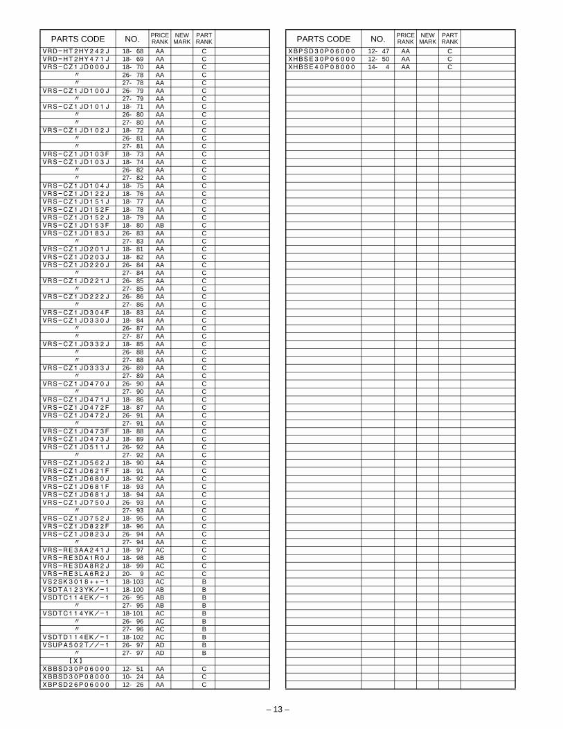
– 13 –
PARTS CODE NO. PRICERANK
NEWMARK
PARTRANK
VRD-HT2HY242J 18- 68 AA CVRD-HT2HY471J 18- 69 AA CVRS-CZ1JD000J 18- 70 AA C
" 26- 78 AA C" 27- 78 AA C
VRS-CZ1JD100J 26- 79 AA C" 27- 79 AA C
VRS-CZ1JD101J 18- 71 AA C" 26- 80 AA C" 27- 80 AA C
VRS-CZ1JD102J 18- 72 AA C" 26- 81 AA C" 27- 81 AA C
VRS-CZ1JD103F 18- 73 AA CVRS-CZ1JD103J 18- 74 AA C
" 26- 82 AA C" 27- 82 AA C
VRS-CZ1JD104J 18- 75 AA CVRS-CZ1JD122J 18- 76 AA CVRS-CZ1JD151J 18- 77 AA CVRS-CZ1JD152F 18- 78 AA CVRS-CZ1JD152J 18- 79 AA CVRS-CZ1JD153F 18- 80 AB CVRS-CZ1JD183J 26- 83 AA C
" 27- 83 AA CVRS-CZ1JD201J 18- 81 AA CVRS-CZ1JD203J 18- 82 AA CVRS-CZ1JD220J 26- 84 AA C
" 27- 84 AA CVRS-CZ1JD221J 26- 85 AA C
" 27- 85 AA CVRS-CZ1JD222J 26- 86 AA C
" 27- 86 AA CVRS-CZ1JD304F 18- 83 AA CVRS-CZ1JD330J 18- 84 AA C
" 26- 87 AA C" 27- 87 AA C
VRS-CZ1JD332J 18- 85 AA C" 26- 88 AA C" 27- 88 AA C
VRS-CZ1JD333J 26- 89 AA C" 27- 89 AA C
VRS-CZ1JD470J 26- 90 AA C" 27- 90 AA C
VRS-CZ1JD471J 18- 86 AA CVRS-CZ1JD472F 18- 87 AA CVRS-CZ1JD472J 26- 91 AA C
" 27- 91 AA CVRS-CZ1JD473F 18- 88 AA CVRS-CZ1JD473J 18- 89 AA CVRS-CZ1JD511J 26- 92 AA C
" 27- 92 AA CVRS-CZ1JD562J 18- 90 AA CVRS-CZ1JD621F 18- 91 AA CVRS-CZ1JD680J 18- 92 AA CVRS-CZ1JD681F 18- 93 AA CVRS-CZ1JD681J 18- 94 AA CVRS-CZ1JD750J 26- 93 AA C
" 27- 93 AA CVRS-CZ1JD752J 18- 95 AA CVRS-CZ1JD822F 18- 96 AA CVRS-CZ1JD823J 26- 94 AA C
" 27- 94 AA CVRS-RE3AA241J 18- 97 AC CVRS-RE3DA1R0J 18- 98 AB CVRS-RE3DA8R2J 18- 99 AC CVRS-RE3LA6R2J 20- 9 AC CVS2SK3018++-1 18- 103 AC BVSDTA123YK/-1 18- 100 AB BVSDTC114EK/-1 26- 95 AB B
" 27- 95 AB BVSDTC114YK/-1 18- 101 AC B
" 26- 96 AC B" 27- 96 AC B
VSDTD114EK/-1 18- 102 AC BVSUPA502T//-1 26- 97 AD B
" 27- 97 AD B[X]
XBBSD30P06000 12- 51 AA CXBBSD30P08000 10- 24 AA CXBPSD26P06000 12- 26 AA C
PARTS CODE NO. PRICERANK
NEWMARK
PARTRANK
XBPSD30P06000 12- 47 AA CXHBSE30P06000 12- 50 AA CXHBSE40P08000 14- 4 AA C

Contains lithium-ion battery. Must be disposed of properly.Remove the battery from the product and contact
federal or state environmentalagencies for information on recycling and disposal options.
(For USA,CANADA)CAUTION FOR BATTERY DISPOSAL
# !

COPYRIGHT 2002 BY SHARP CORPORATIONAll rights reserved.Printed in Japan.
No part of this publication may be reproduced,stored in a retrieval system, or transmitted,
in any form or by any means,electronic, mechanical, photocopying, recording, or otherwise,
without prior written permission of the publisher.
Trademark acknowledgmentsWindows and Windows NT are trademarks of Microsoft Corporation in the U.S.A.and other countries.IBM and PC/AT are trademarks of International Business Machines Corporation.PCL is a trademark of Hewlett-Packard Company.Pentium is a registered trademark of Intel Corporation.All other trademarks and copyrights are the property of their respective owners.
SHARP CORPORATIONDigital Document System GroupProducts Quality Assurance DepartmentYamatokoriyama, Nara 639-1186, Japan
N
c
N2002 May Printed in Japan N
$ !