
Slides SIMOTION Rotary Knife V2 0
24
© Siemens AG 2009. All Rights Reserved. SIMOTION Rotary Knife V2.0
-
Upload
bessem-frija -
Category
Documents
-
view
281 -
download
8
Transcript of Slides SIMOTION Rotary Knife V2 0

© Siemens AG 2009. All Rights Reserved.
SIMOTION Rotary Knife V2.0
© Siemens AG 2009. All Rights Reserved.Industry Sector
Tools
Example Project
Example Configuration
Function Block Overview
Scope of Functionality
Contents of the Application
Benefits when using the Application
Introduction
Converting ToolboxIntroduction
The application SIMOTION Rotary Knife was developed with the objective to address many of the known cross cutter applicationsusing just one application software.
When required, the application can be configured or also changedas a result of openness.
Using the SIMOTION control platform the application SIMOTION Rotary Knife allows to realize cross cutters to be implemented for the widest range of applications, e.g. foil, film, paper, currogatedetc.
Works in combination with: SIMOTION Line Axis
© Siemens AG 2009. All Rights Reserved.Industry Sector
Tools
Example Project
Example Configuration
Function Block Overview
Scope of Functionality
Contents of the Application
Benefits when using the Application
Introduction
Converting ToolboxBenefits when using the Application
Shorter engineering and service times (same look & feel)
Can be used in all programming languages
Industry standards are used
Supported by the various PM Application Centers
Continuously updated in the Intranet
Essentially open source code so that you can adapt the functions to your requirements
User Manuals in German and English
Simple to learn & get to know using application examples
Free of Charge
© Siemens AG 2009. All Rights Reserved.Industry Sector
Tools
Example Project
Example Configuration
Function Block Overview
Scope of Functionality
Contents of the Application
Benefits when using the Application
Introduction
Converting ToolboxContents of the Application
PowerPoint presentation (English / German)
Units / libraries (programming in either ST or MCC)
User Manuals (English / German)
Example project for SIMOTION D demonstration case
Feedback sheets (English / German)
Change log (change history)
© Siemens AG 2009. All Rights Reserved.Industry Sector
Tools
Example Project
Example Configuration
Function Block Overview
Scope of Functionality
Contents of the Application
Benefits when using the Application
Introduction
Converting ToolboxScope of Functionality
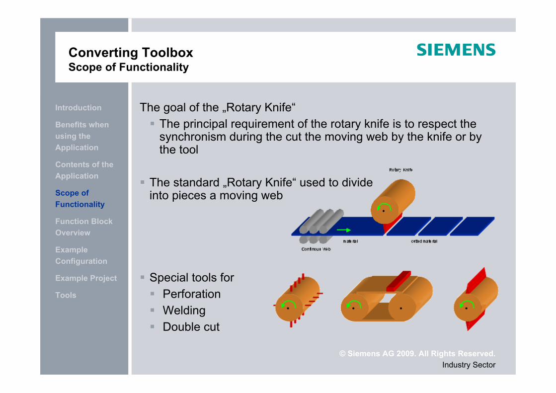
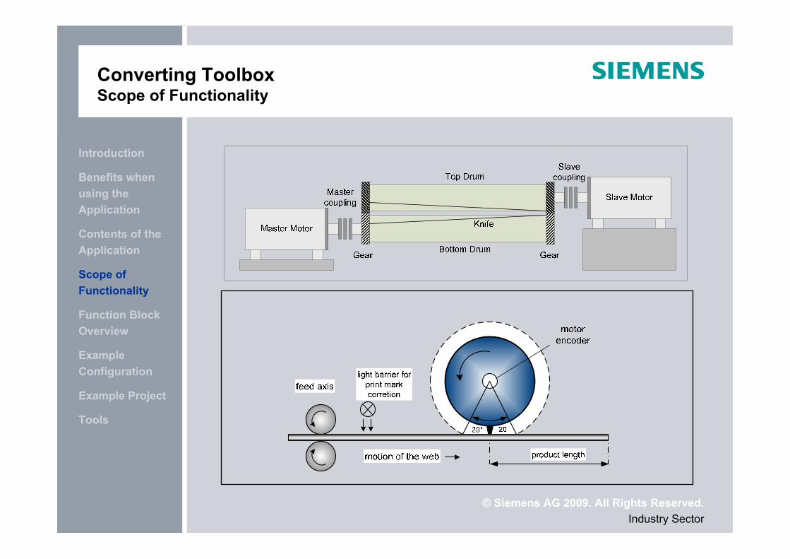
The goal of the „Rotary Knife“ The principal requirement of the rotary knife is to respect the
synchronism during the cut the moving web by the knife or by the tool
The standard „Rotary Knife“ used to divide into pieces a moving web
Special tools for Perforation Welding Double cut
© Siemens AG 2009. All Rights Reserved.Industry Sector
Tools
Example Project
Example Configuration
Function Block Overview
Scope of Functionality
Contents of the Application
Benefits when using the Application
Introduction
Converting ToolboxScope of Functionality
© Siemens AG 2009. All Rights Reserved.Industry Sector
Tools
Example Project
Example Configuration
Function Block Overview
Scope of Functionality
Contents of the Application
Benefits when using the Application
Introduction
Converting ToolboxScope of Functionality
© Siemens AG 2009. All Rights Reserved.Industry Sector
Tools
Example Project
Example Configuration
Function Block Overview
Scope of Functionality
Contents of the Application
Benefits when using the Application
Introduction
Converting ToolboxScope of Functionality
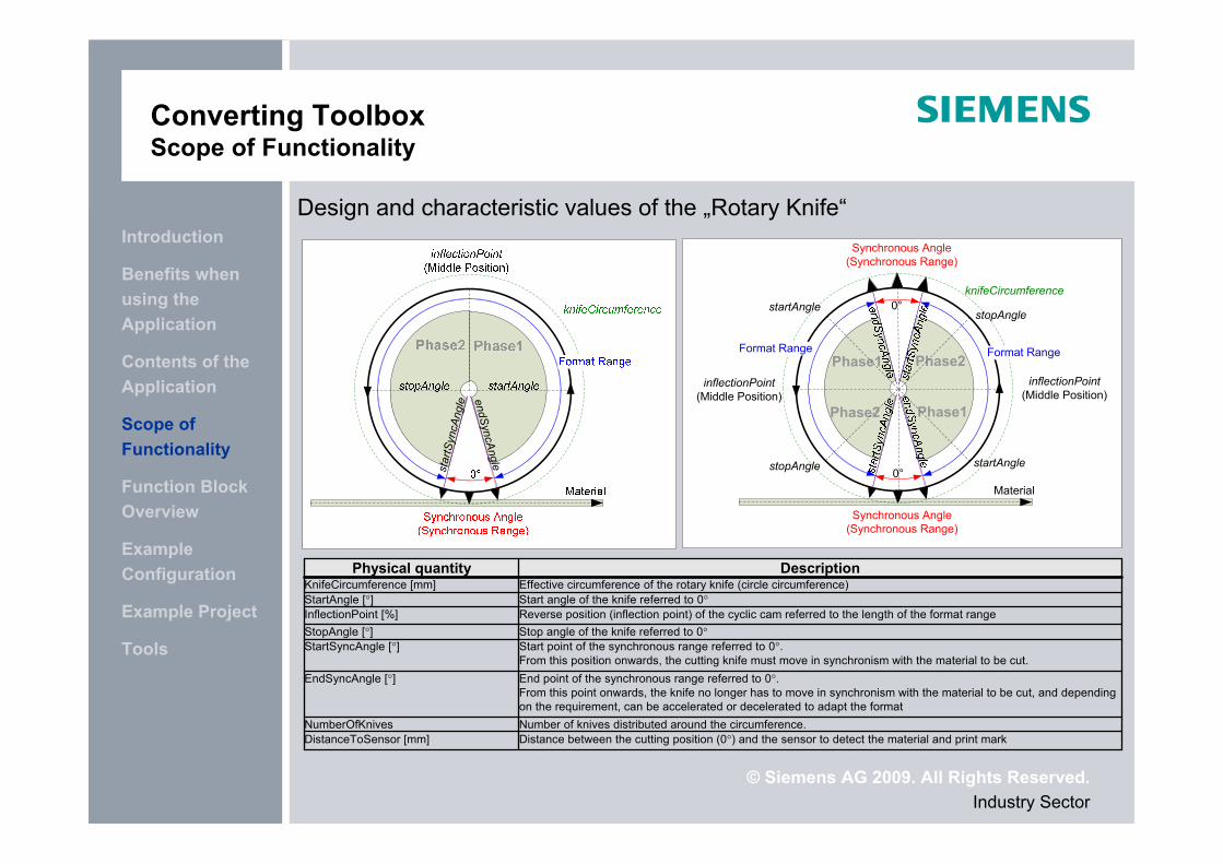
Design and characteristic values of the „Rotary Knife“
star
tSyn
cAng
le endSyncAngle
knifeCircumference
startAngle
stopAngle
inflectionPoint(Middle Position)
Material
Synchronous Angle (Synchronous Range)
Synchronous Angle (Synchronous Range)
Phase1
Phase2inflectionPoint
(Middle Position)
Format RangeFormat Range
0°
0°
Phase1
Phase2
stopAngle
startAngle
Distance between the cutting position (0°) and the sensor to detect the material and print markDistanceToSensor [mm]Number of knives distributed around the circumference.NumberOfKnives
End point of the synchronous range referred to 0°.From this point onwards, the knife no longer has to move in synchronism with the material to be cut, and depending on the requirement, can be accelerated or decelerated to adapt the format
EndSyncAngle [°]
Start point of the synchronous range referred to 0°.From this position onwards, the cutting knife must move in synchronism with the material to be cut.
StartSyncAngle [°]Stop angle of the knife referred to 0°StopAngle [°]Reverse position (inflection point) of the cyclic cam referred to the length of the format rangeInflectionPoint [%]Start angle of the knife referred to 0°StartAngle [°]Effective circumference of the rotary knife (circle circumference)KnifeCircumference [mm]
DescriptionPhysical quantity
© Siemens AG 2009. All Rights Reserved.Industry Sector
Tools
Example Project
Example Configuration
Function Block Overview
Scope of Functionality
Contents of the Application
Benefits when using the Application
Introduction
Converting ToolboxFunktionsübersicht
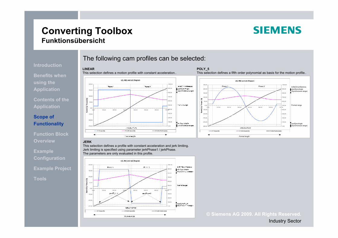
LINEARThis selection defines a motion profile with constant acceleration..
POLY_5This selection defines a fifth order polynomial as basis for the motion profile..
JERKThis selection defines a profile with constant acceleration and jerk limiting. Jerk limiting is specified using parameter jerkPhase1 / jerkPhase. The parameters are only evaluated in this profile.
The following cam profiles can be selected:
Phase 1 Phase 2
endSyncAngle(Synchronous range)
startSyncAngle(Synchronous range)
Format range
inflectionPoint
knifeCircumference
Format length
© Siemens AG 2009. All Rights Reserved.Industry Sector
Tools
Example Project
Example Configuration
Function Block Overview
Scope of Functionality
Contents of the Application
Benefits when using the Application
Introduction
Converting ToolboxFunktionsübersicht
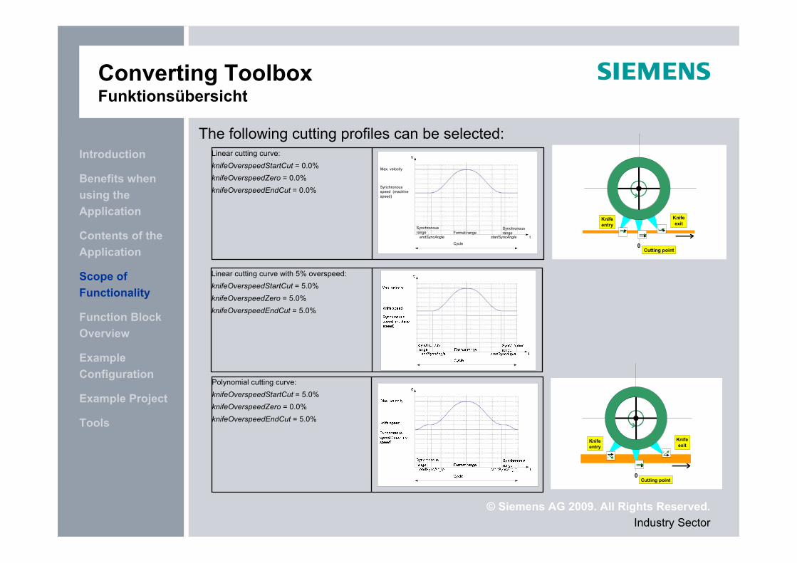
Linear cutting curve:knifeOverspeedStartCut = 0.0%knifeOverspeedZero = 0.0%knifeOverspeedEndCut = 0.0%
Linear cutting curve with 5% overspeed:knifeOverspeedStartCut = 5.0%knifeOverspeedZero = 5.0%knifeOverspeedEndCut = 5.0%
Polynomial cutting curve:knifeOverspeedStartCut = 5.0%knifeOverspeedZero = 0.0%knifeOverspeedEndCut = 5.0%
The following cutting profiles can be selected:V
t
Synchronous speed (machine speed)
Format rangeSynchronous range
Synchronous range
Cycle
Max. velocity
startSyncAngleendSyncAngle
0
Knifeentry
Cutting point
Knifeexit
0
Knifeentry
Cutting point
Knifeexit
© Siemens AG 2009. All Rights Reserved.Industry Sector
Tools
Example Project
Example Configuration
Function Block Overview
Scope of Functionality
Contents of the Application
Benefits when using the Application
Introduction
Converting ToolboxScope of Functionality
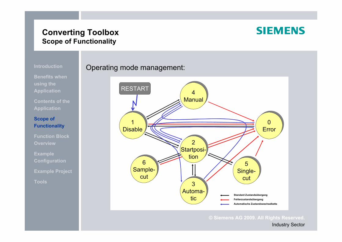
Operating mode management:
1Disable
1Disable
2Startposi-
tion
2Startposi-
tion
4Manual
4Manual
0Error
0Error
3Automa-
tic
3Automa-
tic
RESTART
Standard Zustandsübergang
Fehlerzustandsübergang
Automatische Zustandswechselkette
5Single-
cut
5Single-
cut
6Sample-
cut
6Sample-
cut
© Siemens AG 2009. All Rights Reserved.Industry Sector
Tools
Example Project
Example Configuration
Function Block Overview
Scope of Functionality
Contents of the Application
Benefits when using the Application
Introduction
Converting ToolboxFunktionsübersicht
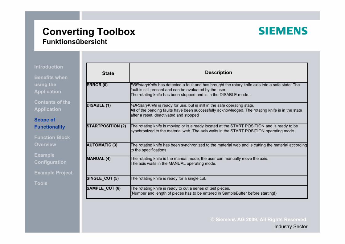
The rotating knife is ready to cut a series of test pieces.(Number and length of pieces has to be entered in SampleBuffer before starting!)
SAMPLE_CUT (6)
The rotating knife is ready for a single cut.SINGLE_CUT (5)
The rotating knife is the manual mode; the user can manually move the axis.The axis waits in the MANUAL operating mode.
MANUAL (4)
The rotating knife has been synchronized to the material web and is cutting the material according to the specifications
AUTOMATIC (3)
The rotating knife is moving or is already located at the START POSITION and is ready to be synchronized to the material web. The axis waits in the START POSITION operating mode
STARTPOSITION (2)
FBRotaryKnife is ready for use, but is still in the safe operating state.All of the pending faults have been successfully acknowledged. The rotating knife is in the state after a reset, deactivated and stopped
DISABLE (1)
FBRotaryKnife has detected a fault and has brought the rotary knife axis into a safe state. The fault is still present and can be evaluated by the user.The rotating knife has been stopped and is in the DISABLE mode. .
ERROR (0)
DescriptionState
© Siemens AG 2009. All Rights Reserved.Industry Sector
Tools
Example Project
Example Configuration
Function Block Overview
Scope of Functionality
Contents of the Application
Benefits when using the Application
Introduction
Converting ToolboxScope of Functionality
Parameterization instead of programming
Following properties can be covered the function „Rotary Knife“:
Linear cut curve with adaptable over speed In the cut domain the knife and the web have the same velocity
Polynomial cam Overshoot can be avoided
Print mark correction with settable correction speed Die correction occurs out of the synchronous domain
Multi knife system The Rotary Knife-FB can be used also with multi knife drum
Settable Standby position of the knife Can be set with a parameter from the user
Predefined start and stop behavior In order to start and stop the knife without jerk
Dynamic change of the cut length Cam profile online adjusted by print mark and by format change
© Siemens AG 2009. All Rights Reserved.Industry Sector
Tools
Example Project
Example Configuration
Function Block Overview
Scope of Functionality
Contents of the Application
Benefits when using the Application
Introduction
Converting ToolboxFunction Block Overview
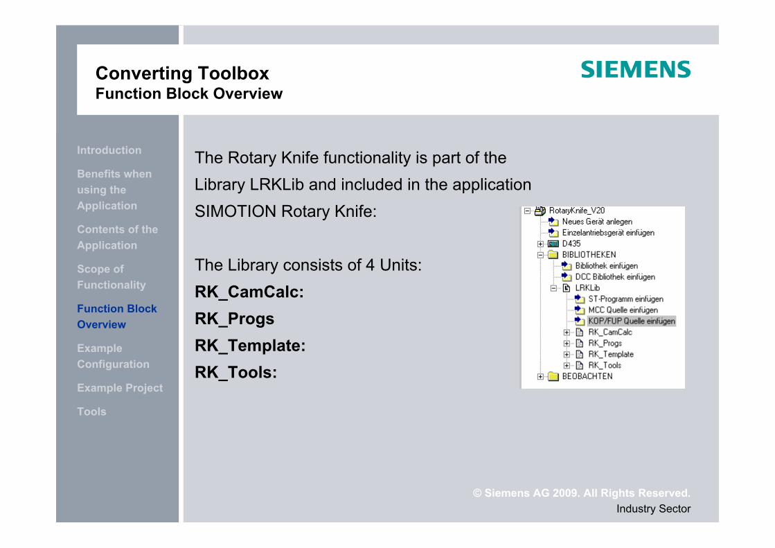
The Rotary Knife functionality is part of the Library LRKLib and included in the application SIMOTION Rotary Knife:
The Library consists of 4 Units:RK_CamCalc:RK_ProgsRK_Template:RK_Tools:
© Siemens AG 2009. All Rights Reserved.Industry Sector
Tools
Example Project
Example Configuration
Function Block Overview
Scope of Functionality
Contents of the Application
Benefits when using the Application
Introduction
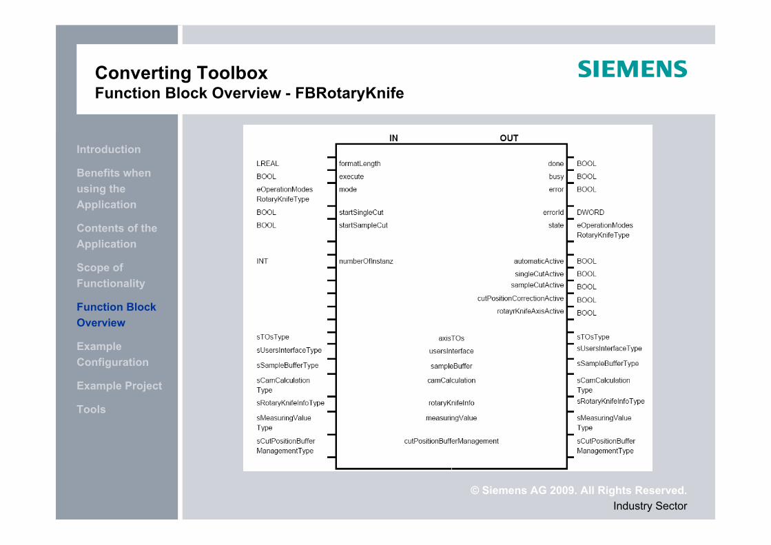
Converting ToolboxFunction Block Overview - FBRotaryKnife
© Siemens AG 2009. All Rights Reserved.Industry Sector
Tools
Example Project
Example Configuration
Function Block Overview
Scope of Functionality
Contents of the Application
Benefits when using the Application
Introduction
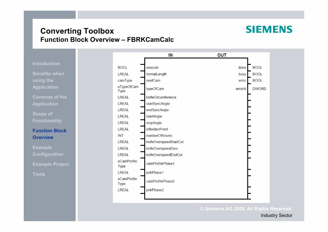
Converting ToolboxFunction Block Overview – FBRKCamCalc
© Siemens AG 2009. All Rights Reserved.Industry Sector
Tools
Example Project
Example Configuration
Function Block Overview
Scope of Functionality
Contents of the Application
Benefits when using the Application
Introduction
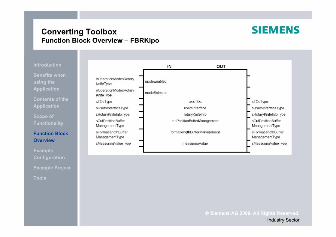
Converting ToolboxFunction Block Overview – FBRKIpo
© Siemens AG 2009. All Rights Reserved.Industry Sector
Tools
Example Project
Example Configuration
Function Block Overview
Scope of Functionality
Contents of the Application
Benefits when using the Application
Introduction
Converting ToolboxExample Configuration
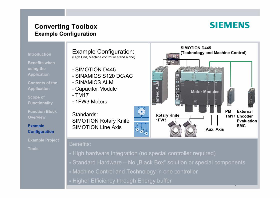
Example Configuration: (High End, Machine control or stand alone)
• SIMOTION D445• SINAMICS S120 DC/AC• SINAMICS ALM• Capacitor Module• TM17• 1FW3 Motors
Standards:SIMOTION Rotary KnifeSIMOTION Line Axis
Benefits: High hardware integration (no special controller required) Standard Hardware – No „Black Box“ solution or special components Machine Control and Technology in one controller Higher Efficiency through Energy buffer
SIMOTION D445 (Technology and Machine Control)
Rotary Knife1FW3
PMTM17
ExternalEncoderEvaluationSMC
Infe
ed A
LM
SIM
OTI
ON
D44
5
Aux. Axis
Motor Modules
© Siemens AG 2009. All Rights Reserved.Industry Sector
Tools
Example Project
Example Configuration
Function Block Overview
Scope of Functionality
Contents of the Application
Benefits when using the Application
Introduction
Converting ToolboxExample Configuration
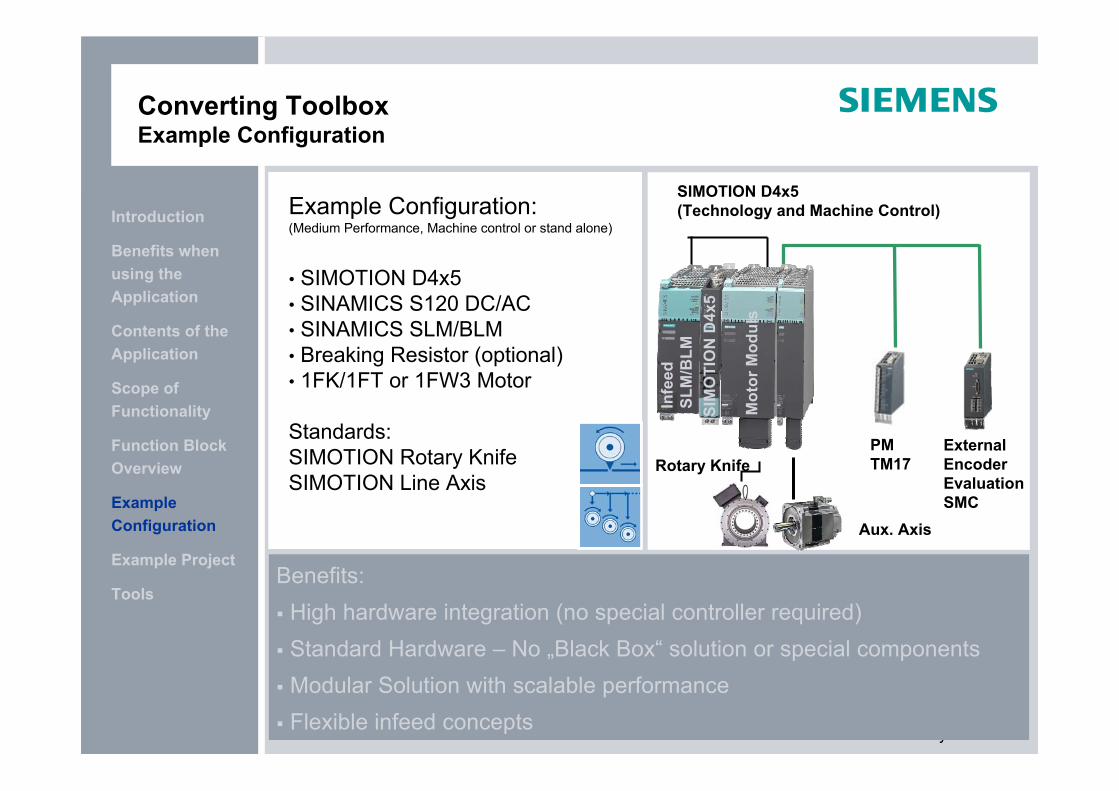
Example Configuration: (Medium Performance, Machine control or stand alone)
• SIMOTION D4x5• SINAMICS S120 DC/AC• SINAMICS SLM/BLM• Breaking Resistor (optional)• 1FK/1FT or 1FW3 Motor
Standards:SIMOTION Rotary KnifeSIMOTION Line Axis
Benefits: High hardware integration (no special controller required) Standard Hardware – No „Black Box“ solution or special components Modular Solution with scalable performance Flexible infeed concepts
SIMOTION D4x5 (Technology and Machine Control)
Rotary KnifePMTM17
ExternalEncoderEvaluationSMC
Infe
ed
SLM
/BLM
SIM
OTI
ON
D4x
5
Mot
or M
odul
s
Aux. Axis
© Siemens AG 2009. All Rights Reserved.Industry Sector
Tools
Example Project
Example Configuration
Function Block Overview
Scope of Functionality
Contents of the Application
Benefits when using the Application
Introduction
Converting ToolboxExample Configuration
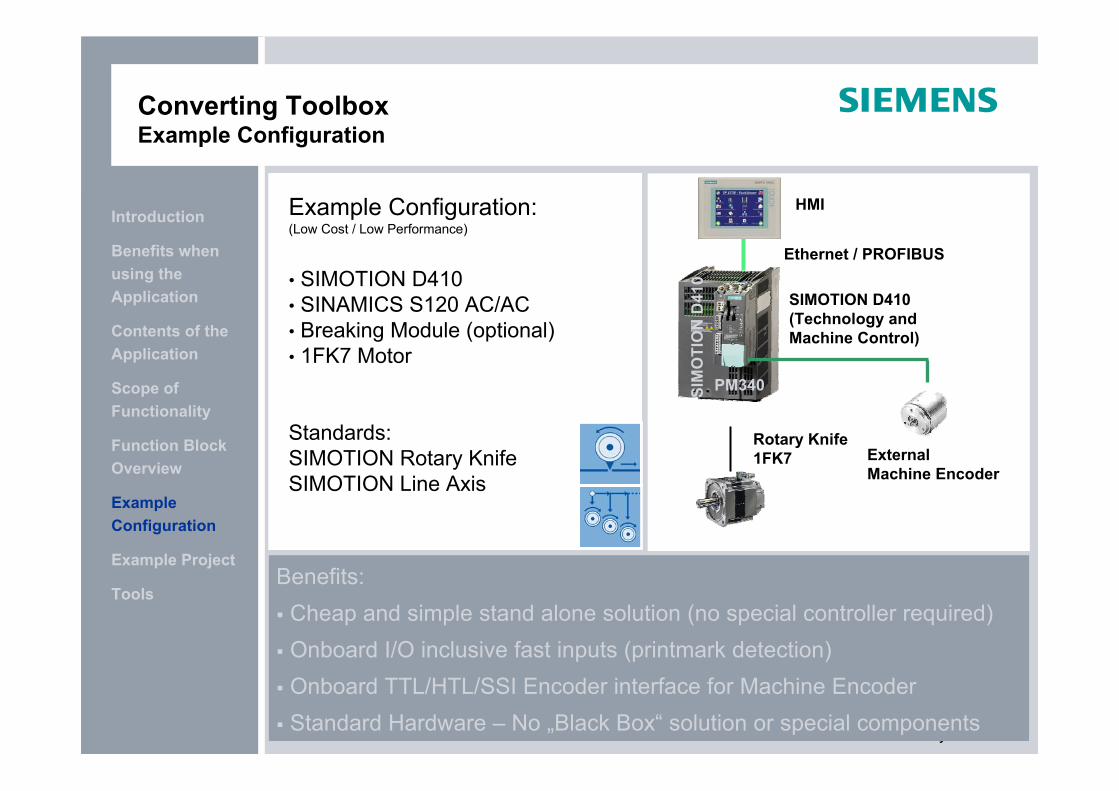
Example Configuration:(Low Cost / Low Performance)
• SIMOTION D410• SINAMICS S120 AC/AC• Breaking Module (optional)• 1FK7 Motor
Standards:SIMOTION Rotary KnifeSIMOTION Line Axis
Benefits: Cheap and simple stand alone solution (no special controller required) Onboard I/O inclusive fast inputs (printmark detection) Onboard TTL/HTL/SSI Encoder interface for Machine Encoder Standard Hardware – No „Black Box“ solution or special components
SIMOTION D410 (Technology and Machine Control)
Rotary Knife1FK7 External
Machine Encoder
SIM
OTI
ON
D41
0
Ethernet / PROFIBUS
HMI
PM340
© Siemens AG 2009. All Rights Reserved.Industry Sector
Tools
Example Project
Example Configuration
Function Block Overview
Scope of Functionality
Contents of the Application
Benefits when using the Application
Introduction
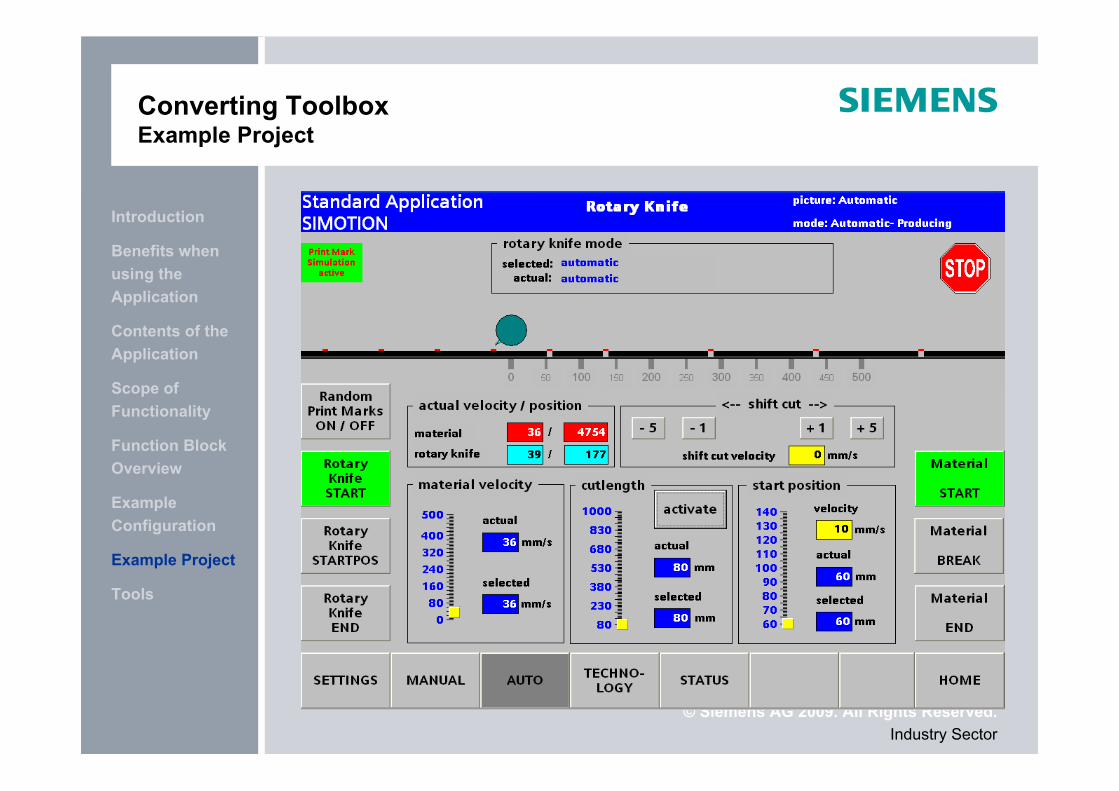
Converting ToolboxExample Project
© Siemens AG 2009. All Rights Reserved.Industry Sector
Tools
Example Project
Example Configuration
Function Block Overview
Scope of Functionality
Contents of the Application
Benefits when using the Application
Introduction
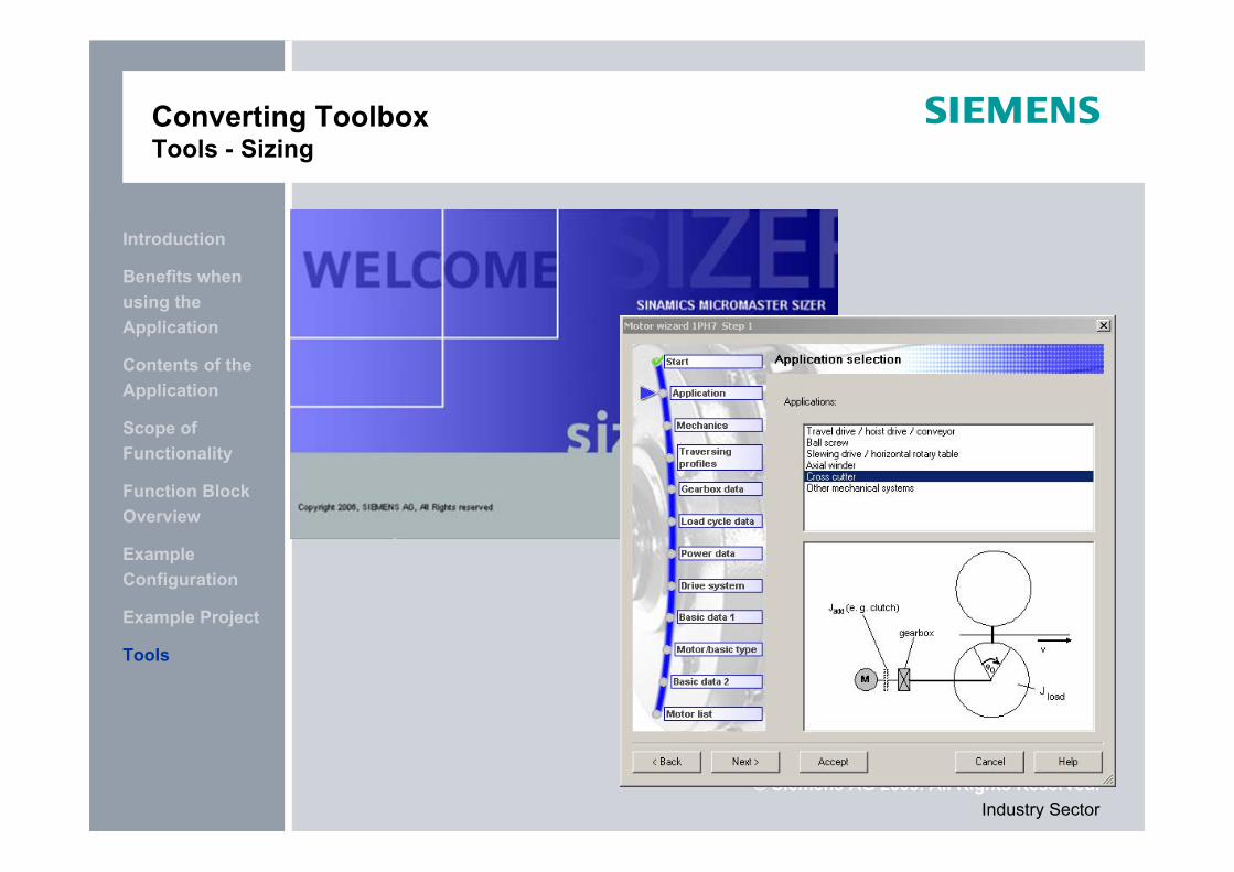
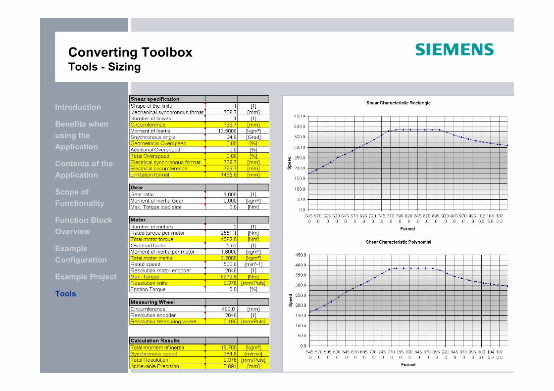
Converting ToolboxTools - Sizing
© Siemens AG 2009. All Rights Reserved.Industry Sector
Tools
Example Project
Example Configuration
Function Block Overview
Scope of Functionality
Contents of the Application
Benefits when using the Application
Introduction
Converting ToolboxTools - Sizing
© Siemens AG 2009. All Rights Reserved.
Application CenterI DT MC PM APC
Frauenauracher Str. 80D-91056 Erlangen
E-Mail: [email protected]
Thank you for your attention!


![Rotary Knife - 三菱電機 Mitsubishi Electricdl.mitsubishielectric.co.jp/dl/fa/software/library/ssc/... · 2015-06-01 · Rotary Knife [System Configuration] [Mitsubishi solution]](https://static.fdocuments.us/doc/165x107/5f032cb87e708231d407e8c3/rotary-knife-ee-mitsubishi-2015-06-01-rotary-knife-system-configuration.jpg)