TM.MPIEC.01 Rotary Knife ASP for MPiec Controllers
17
Title: Rotary Knife Application Solution Package for MPiec Controllers Product(s): MP2XXXiec, MP3XXXiec Doc. No. TM.MPIEC.01 Revision 10 April 4, 2018 Page 1 of 17 TECHNICAL MANUAL Contents APPLICATION OVERVIEW ........................................................................... 2 APPLICATION HIGHLIGHTS ........................................................................ 2 IMPLEMENTATION ...................................................................................... 2 1. Configure the Master and Knife axes .............................................................. 3 2. Add User Libraries ........................................................................................ 3 3. Generating cam profiles ................................................................................ 3 3 a) Generating cam profiles using RotaryKnifeCamGen…………………………………..4 3 b) Generating custom cam profiles................................................................ 7 4. Setting the CamMasterCycle .......................................................................... 9 5. Rotary Knife Motion .....................................................................................10 5 a) Applications without product registration .................................................. 10 5 b) Applications requiring product registration................................................13
Transcript of TM.MPIEC.01 Rotary Knife ASP for MPiec Controllers

Title: Rotary Knife Application Solution Package for MPiec Controllers Product(s): MP2XXXiec, MP3XXXiec Doc. No. TM.MPIEC.01
Revision 10 April 4, 2018 Page 1 of 17
TECHNICAL MANUAL
Contents APPLICATION OVERVIEW ........................................................................... 2 APPLICATION HIGHLIGHTS ........................................................................ 2 IMPLEMENTATION ...................................................................................... 2
1. Configure the Master and Knife axes .............................................................. 3 2. Add User Libraries ........................................................................................ 3 3. Generating cam profiles ................................................................................ 3
3 a) Generating cam profiles using RotaryKnifeCamGen…………………………………..4 3 b) Generating custom cam profiles................................................................ 7
4. Setting the CamMasterCycle .......................................................................... 9 5. Rotary Knife Motion ..................................................................................... 10
5 a) Applications without product registration .................................................. 10 5 b) Applications requiring product registration ................................................ 13

Revision 10 April 4, 2018 Page 2 of 17
TECHNICAL MANUAL
APPLICATION OVERVIEW The Rotary Knife Application Solution Package (ASP) offers an easy way to implement rotary knife or rotary placer applications. This solution package was designed for machines that process products spaced at fixed intervals or machines must make dynamic corrections based on a product registration mark. The Rotary Knife ASP project can be used as a starting point template on which the user can complete the application, or the ASP can be added as a user library into an existing project. The Rotary Knife ASP focuses only on the core motion features required to operate a Rotary Knife and does not include other functionality such as servo enable, homing, manual modes, alarm handling, etc. The user is responsible for incorporating other basic logic functionality required for the application. Starter projects are provided with SW.MPIEC.01. Type ‘SW.MPIEC.01’ in the search bar on Yaskawa.com (first link) or use the following link. URL: https://www.yaskawa.com/downloads/search-index/details?showType=details&docnum=SW.MPIEC.01 The main steps involved in completing the Rotary Knife application are:
1) Configure the axes in Hardware Configuration. 2) Import all required user libraries. 3) Create cam profiles using one of two methods: a) Use the RotaryKnifeCamGen function block in the ASP; b) Create custom cam profiles if the application requires it. 4) Home the rotary knife axis and set the CamMasterCycle. 5) Program motion for the rotary knife using one of two methods: a) For applications that do not require registration, use the RotaryKnife function block. b) For applications that require registration based corrections, use the RotaryKnife_Registration function block. APPLICATION HIGHLIGHTS
1. Designed for Rotary Knife or Rotary Placer with or without product registration. 2. Uses Cam motion with CamBlend feature to reduce jerk on a knife axis that must stop and start while the line (master) is moving. 3. Advanced motion algorithm called a Bezier curve is utilized to prevent reversed knife motion for certain combinations of product length and knife diameter. IMPLEMENTATION

Revision 10 April 4, 2018 Page 3 of 17
TECHNICAL MANUAL
1. Configure the Master and Knife axes Configure the master and slave axes in the Hardware Configuration. Configure the slave axis as a Rotary load with a Machine Cycle of 360 degrees. The master load type is typically configured as Linear. 2. Add User Libraries If the Rotary Knife ASP is applied as a user as a library:
1. Delete all Data Type files from the main project. 2. Add the Y_Motion firmware library to the main project Add the following toolboxes to the main project in the order in which they appear in Figure 1 below:
1. DataTypes_Toolbox_v350 2. Math_Toolbox_v350 3. Yaskawa_Toolbox_v350 4. PLCopen_Toolbox_v350 5. Cam_Toolbox_v340 6. Add the Rotary Knife ASP project as a User library in the main project. (MP2600 or MP3300 project)
FIGURE 1: USER LIBRARY STRUCTURE
3. Generating cam profiles The user has two options for creating cam tables:
1) Use the RotaryKnifeCamGen function block which generates all necessary cam tables. This function block creates cam profiles using straight line and Tangent Matching or Bezier segments. 2) Create custom cam profiles using Y_CamFileSelect, CamGenerator, and Y_CamStructSelect. This is only necessary for application with unique mechanisms.
Revision 10 April 4, 2018 Page 4 of 17
TECHNICAL MANUAL
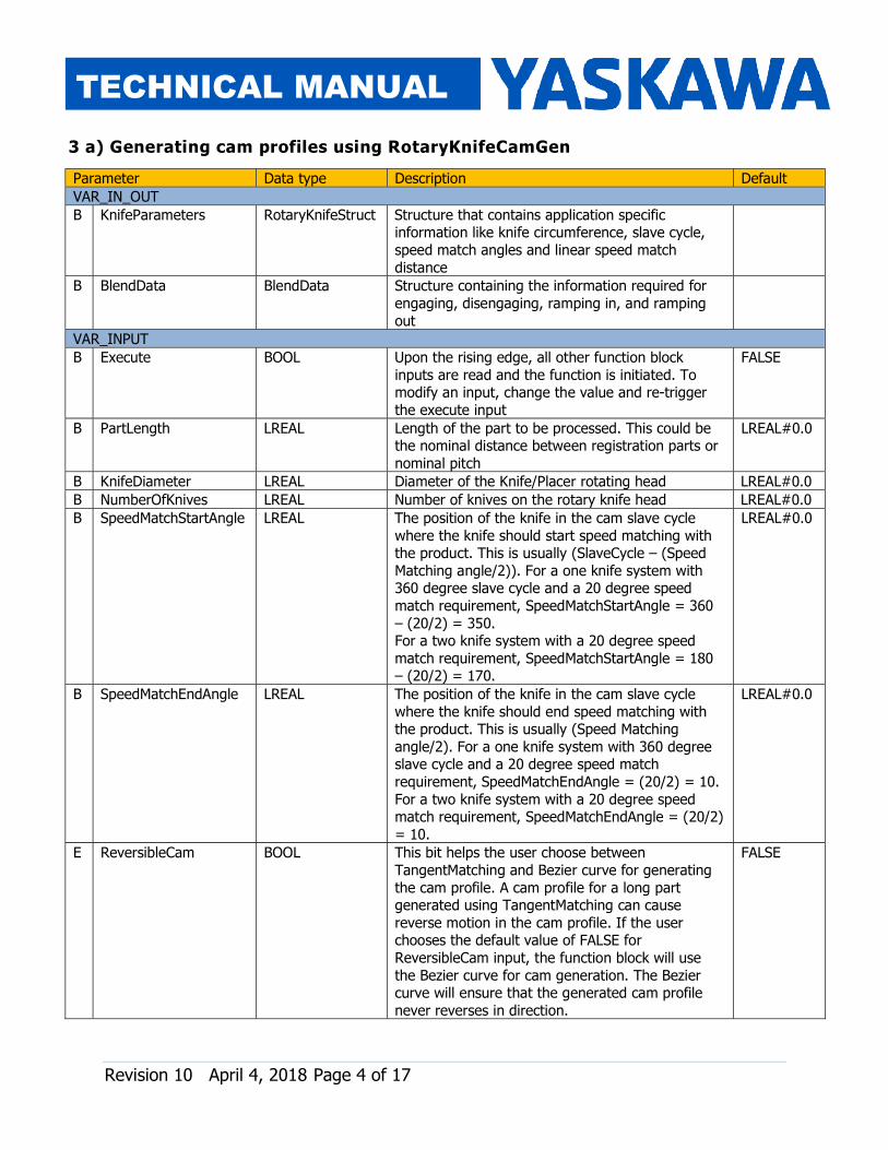
Parameter Data type Description Default VAR_IN_OUT B KnifeParameters RotaryKnifeStruct Structure that contains application specific information like knife circumference, slave cycle, speed match angles and linear speed match distance
B BlendData BlendData Structure containing the information required for engaging, disengaging, ramping in, and ramping out
VAR_INPUT B Execute BOOL Upon the rising edge, all other function block inputs are read and the function is initiated. To modify an input, change the value and re-trigger the execute input
FALSE
B PartLength LREAL Length of the part to be processed. This could be the nominal distance between registration parts or nominal pitch LREAL#0.0
B KnifeDiameter LREAL Diameter of the Knife/Placer rotating head LREAL#0.0 B NumberOfKnives LREAL Number of knives on the rotary knife head LREAL#0.0 B SpeedMatchStartAngle LREAL The position of the knife in the cam slave cycle where the knife should start speed matching with the product. This is usually (SlaveCycle – (Speed Matching angle/2)). For a one knife system with 360 degree slave cycle and a 20 degree speed match requirement, SpeedMatchStartAngle = 360 – (20/2) = 350. For a two knife system with a 20 degree speed match requirement, SpeedMatchStartAngle = 180 – (20/2) = 170.
LREAL#0.0
B SpeedMatchEndAngle LREAL The position of the knife in the cam slave cycle where the knife should end speed matching with the product. This is usually (Speed Matching angle/2). For a one knife system with 360 degree slave cycle and a 20 degree speed match requirement, SpeedMatchEndAngle = (20/2) = 10. For a two knife system with a 20 degree speed match requirement, SpeedMatchEndAngle = (20/2) = 10.
LREAL#0.0
E ReversibleCam BOOL This bit helps the user choose between TangentMatching and Bezier curve for generating the cam profile. A cam profile for a long part generated using TangentMatching can cause reverse motion in the cam profile. If the user chooses the default value of FALSE for ReversibleCam input, the function block will use the Bezier curve for cam generation. The Bezier curve will ensure that the generated cam profile never reverses in direction.
FALSE
3 a) Generating cam profiles using RotaryKnifeCamGen

Revision 10 April 4, 2018 Page 5 of 17
TECHNICAL MANUAL
Add RotaryKnifeCamGen to a POU running in a slow / low priority task (1000 ms task update rate).
FIGURE 2: ROTARYKNIFECAMGEN FUNCTION BLOCK
ErrorID Meaning 10180 SpeedMatchLengthError: PartLength <= Speed Match Length 10181 SpeedMatchLimitError: SlaveCycle <= SpeedMatch Start angle 10182 SpeedMatchRangeError: SpeedMatch start angle <= SpeedMatch end angle All other ErrorIDs are listed under help for CamGenerator (Cam_Toolbox), CamTableManager (Cam_Toolbox), Y_CamStructSelect (PLCopenPlus_v_2_2a).
(Help for cam toolbox: www.yaskawa.com/iectb)
VAR_OUTPUT B Done BOOL Set high when the commanded action has been completed successfully. If another block takes control before the action is completed, the Done output will not be set. This output is reset when execute goes low.
B Busy BOOL Set high upon the rising edge of the 'Execute' input, and reset if Done, or Error is true. B Error BOOL Set high if error has occurred during the execution of the function block. This output is cleared when 'Execute' goes low
E ErrorID UINT If error is true, this output provides the Error ID. This output is reset when 'Execute' goes low
Revision 10 April 4, 2018 Page 6 of 17
TECHNICAL MANUAL
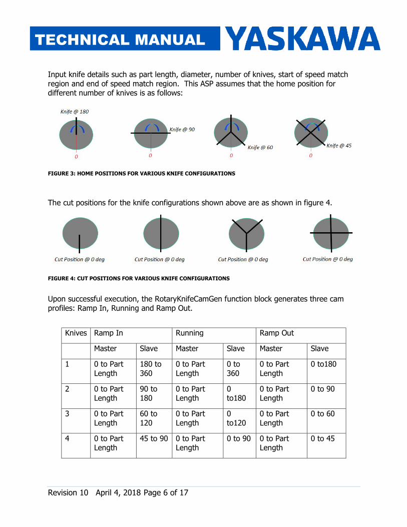
Input knife details such as part length, diameter, number of knives, start of speed match region and end of speed match region. This ASP assumes that the home position for different number of knives is as follows:
FIGURE 3: HOME POSITIONS FOR VARIOUS KNIFE CONFIGURATIONS The cut positions for the knife configurations shown above are as shown in figure 4.
FIGURE 4: CUT POSITIONS FOR VARIOUS KNIFE CONFIGURATIONS Upon successful execution, the RotaryKnifeCamGen function block generates three cam profiles: Ramp In, Running and Ramp Out.
Knives Ramp In Running Ramp Out Master Slave Master Slave Master Slave 1 0 to Part Length 180 to 360 0 to Part Length 0 to 360 0 to Part Length 0 to180
2 0 to Part Length 90 to 180 0 to Part Length 0 to180 0 to Part Length 0 to 90
3 0 to Part Length 60 to 120 0 to Part Length 0 to120 0 to Part Length 0 to 60
4 0 to Part Length 45 to 90 0 to Part Length 0 to 90 0 to Part Length 0 to 45
Revision 10 April 4, 2018 Page 7 of 17
TECHNICAL MANUAL
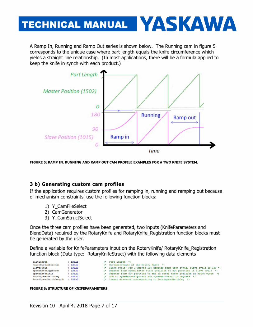
A Ramp In, Running and Ramp Out series is shown below. The Running cam in figure 5 corresponds to the unique case where part length equals the knife circumference which yields a straight line relationship. (In most applications, there will be a formula applied to keep the knife in synch with each product.)
FIGURE 5: RAMP IN, RUNNING AND RAMP OUT CAM PROFILE EXAMPLES FOR A TWO KNIFE SYSTEM.
3 b) Generating custom cam profiles If the application requires custom profiles for ramping in, running and ramping out because of mechanism constraints, use the following function blocks:
1) Y_CamFileSelect 2) CamGenerator 3) Y_CamStructSelect Once the three cam profiles have been generated, two inputs (KnifeParameters and BlendData) required by the RotaryKnife and RotaryKnife_Registration function blocks must be generated by the user. Define a variable for KnifeParameters input on the RotaryKnife/ RotaryKnife_Registration function block (Data type: RotaryKnifeStruct) with the following data elements
FIGURE 6: STRUCTURE OF KNIFEPARAMETERS

Revision 10 April 4, 2018 Page 8 of 17
TECHNICAL MANUAL
FIGURE 7: ELEMENTS OF KNIFEPARAMETERS Consider a two-knife system with a diameter of 5.0 inches. The knife circumference is 5.0 x 3.1415 = 15.707 inches. The slave cycle for a two knife system is 180 degrees. To achieve a speed matching angle of 10 degrees before and after the cut, set SpeedMatchApproach = 10 and SpeedMatchExit = 10. TotalSpeedMatchDeg = 20 degrees. TotalSpeedMatchLength = (20 x 15.707) / 180 = 1.74”
SpeedMatchApproach
SpeedMatchExit
Revision 10 April 4, 2018 Page 9 of 17
TECHNICAL MANUAL
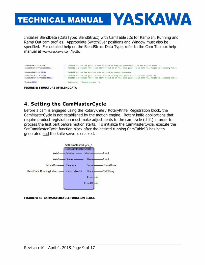
Initialize BlendData (DataType: BlendStruct) with CamTable IDs for Ramp In, Running and Ramp Out cam profiles. Appropriate SwitchOver positions and Window must also be specified. For detailed help on the BlendStruct Data Type, refer to the Cam Toolbox help manual at www.yaskawa.com/iectb.
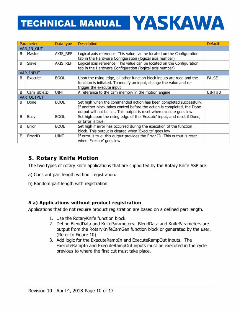
FIGURE 8: STRUCTURE OF BLENDDATA 4. Setting the CamMasterCycle Before a cam is engaged using the RotaryKnife / RotaryKnife_Registration block, the CamMasterCycle is not established by the motion engine. Rotary knife applications that require product registration must make adjustments to the cam cycle (shift) in order to process the first part before motion starts. To initialize the CamMasterCycle, execute the SetCamMasterCycle function block after the desired running CamTableID has been generated and the knife servo is enabled.
FIGURE 9: SETCAMMASTERCYCLE FUNCTION BLOCK
Revision 10 April 4, 2018 Page 10 of 17
TECHNICAL MANUAL
Parameter Data type Description Default VAR_IN_OUT B Master AXIS_REF Logical axis reference. This value can be located on the Configuration tab in the Hardware Configuration (logical axis number) B Slave AXIS_REF Logical axis reference. This value can be located on the Configuration tab in the Hardware Configuration (logical axis number) VAR_INPUT B Execute BOOL Upon the rising edge, all other function block inputs are read and the function is initiated. To modify an input, change the value and re-trigger the execute input
FALSE
B CamTableID UINT A reference to the cam memory in the motion engine UINT#0 VAR_OUTPUT B Done BOOL Set high when the commanded action has been completed successfully. If another block takes control before the action is completed, the Done output will not be set. This output is reset when execute goes low.
B Busy BOOL Set high upon the rising edge of the 'Execute' input, and reset if Done, or Error is true. B Error BOOL Set high if error has occurred during the execution of the function block. This output is cleared when 'Execute' goes low E ErrorID UINT If error is true, this output provides the Error ID. This output is reset when 'Execute' goes low
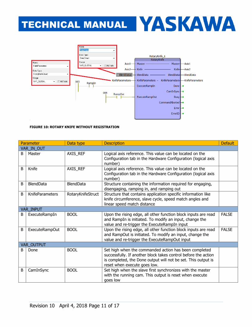
5. Rotary Knife Motion The two types of rotary knife applications that are supported by the Rotary Knife ASP are: a) Constant part length without registration. b) Random part length with registration. 5 a) Applications without product registration Applications that do not require product registration are based on a defined part length.
1. Use the RotaryKnife function block. 2. Define BlendData and KnifeParameters. BlendData and KnifeParameters are output from the RotaryKnifeCamGen function block or generated by the user. (Refer to Figure 10) 3. Add logic for the ExecuteRampIn and ExecuteRampOut inputs. The ExecuteRampIn and ExecuteRampOut inputs must be executed in the cycle previous to where the first cut must take place.
Revision 10 April 4, 2018 Page 11 of 17
TECHNICAL MANUAL
FIGURE 10: ROTARY KNIFE WITHOUT REGISTRATION
Parameter Data type Description Default VAR_IN_OUT B Master AXIS_REF Logical axis reference. This value can be located on the Configuration tab in the Hardware Configuration (logical axis number)
B Knife AXIS_REF Logical axis reference. This value can be located on the Configuration tab in the Hardware Configuration (logical axis number)
B BlendData BlendData Structure containing the information required for engaging, disengaging, ramping in, and ramping out B KnifeParameters RotaryKnifeStruct Structure that contains application specific information like knife circumference, slave cycle, speed match angles and linear speed match distance
VAR_INPUT B ExecuteRampIn BOOL Upon the rising edge, all other function block inputs are read and RampIn is initiated. To modify an input, change the value and re-trigger the ExecuteRampIn input
FALSE
B ExecuteRampOut BOOL Upon the rising edge, all other function block inputs are read and RampOut is initiated. To modify an input, change the value and re-trigger the ExecuteRampOut input FALSE
VAR_OUTPUT B Done BOOL Set high when the commanded action has been completed successfully. If another block takes control before the action is completed, the Done output will not be set. This output is reset when execute goes low.
B CamInSync BOOL Set high when the slave first synchronizes with the master with the running cam. This output is reset when execute goes low

Revision 10 April 4, 2018 Page 12 of 17
TECHNICAL MANUAL
B Busy BOOL Set high upon the rising edge of the 'Execute' input, and reset if Done, or Error is true. B CommandAborted BOOL Set high if motion is aborted by another motion command or MC_Stop. This output is cleared with the same behavior as the Done output
B Error BOOL Set high if error has occurred during the execution of the function block. This output is cleared when 'Execute' goes low
E ErrorID UINT If error is true, this output provides the Error ID. This output is reset when 'Execute' goes low
ErrorID Meaning All All ErrorIDs are listed under help for CamBlend (Cam_Toolbox), MC_ReadParameter (PLCopenPlus_v_2_2a), Y_SlaveOffset (PLCopenPlus_v_2_2a), and MC_ReadActualVelocity (PLCopenPlus_v_2_2a).
(Help for cam toolbox: www.yaskawa.com/iectb)
FIGURE 11: CONTROL OF ROTARY KNIFE WITHOUT REGISTRATION

Revision 10 April 4, 2018 Page 13 of 17
TECHNICAL MANUAL
5 b) Applications requiring product registration Use the ASP’s RotaryKnife_Registration function block.
FIGURE 12: ROTARY KNIFE WITH REGISTRATION
Parameter Data type Description Default VAR_IN_OUT B Master AXIS_REF Logical axis reference. This value can be located on the Configuration tab in the Hardware Configuration (logical axis number)
B Knife AXIS_REF Logical axis reference. This value can be located on the Configuration tab in the Hardware Configuration (logical axis number)
B RegistrationData ProductBufferStruct Structure containing all information for the circular buffer to operate B ControlData CamSyncStruct Structure containing all information to allow both the CamControl and CamShiftControl to make decisions to run the cam function effectively
B BlendData BlendData Structure containing the information required for engaging, disengaging, ramping in, and ramping out
B KnifeParameters RotaryKnifeStruct Structure that contains application specific information like knife circumference, slave cycle, speed match angles and linear speed match distance

Revision 10 April 4, 2018 Page 14 of 17
TECHNICAL MANUAL
VAR_INPUT B Enable BOOL The function will continue to execute while enable is held high FALSE B StopBuffering BOOL Upon the rising edge, products stop getting added to the product buffer. The products that are already in the buffer get processed by the function block even after the StopBuffering input is TRUE.
FALSE
VAR_OUTPUT B Valid BOOL Indicates that the outputs of the function are valid B Error BOOL Set high if error has occurred during the execution of the function block. This output is cleared when 'Execute' goes low
E ErrorID UINT If error is true, this output provides the Error ID. This output is reset when 'Execute' goes low
E BufferLevel INT Number of products in the product buffer that have not been processed yet E ItemsProcessed UDINT Provides a count of the number of products processed since this function was enabled
ErrorID Meaning 10183 SensorDistanceError: Sensor distance < = Part length. Cam blend cannot be accomplished with such a set up 10184 EngageDistanceError: Safe Engage Distance <= Part length. Cam Blend cannot be accomplished with such a set up All All ErrorIDs are listed under help for CamControl (Cam_Toolbox), CamBlend (Cam_Toolbox), CamShiftControl (CamToolbox), ProductBuffer (PLCopen_Toolbox), MC_ReadParameter (PLCopenPlus_v_2_2a), Y_SlaveOffset (PLCopenPlus_v_2_2a), and MC_ReadActualVelocity (PLCopenPlus_v_2_2a).
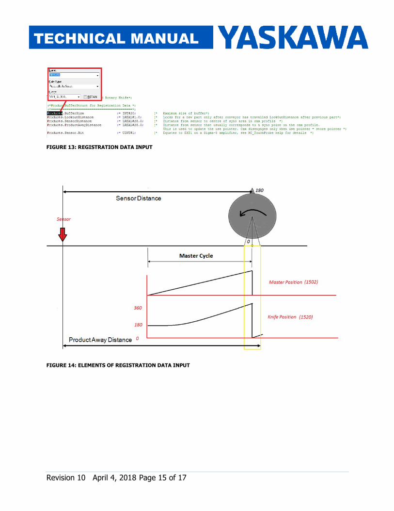
(Help for cam toolbox: www.yaskawa.com/iectb) 1. Define the BlendData and KnifeParameters inputs on the RotaryKnife_Registration function block. If the RotaryKnifeCamGen is used, these two variables are outputs of RotaryKnifeCamGen function block. 2. Define a variable for the RegistrationData input (Data type: ProductBufferStruct) on the RotaryKnife_Registration function block. 3. Note: Ensure that the SensorDistance is greater than the PartLength. This is necessary for the cam blend functionality in the RotaryKnife_Registration function block to work correctly.
Revision 10 April 4, 2018 Page 15 of 17
TECHNICAL MANUAL
FIGURE 13: REGISTRATION DATA INPUT
FIGURE 14: ELEMENTS OF REGISTRATION DATA INPUT
Revision 10 April 4, 2018 Page 16 of 17
TECHNICAL MANUAL
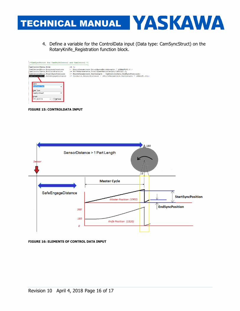
4. Define a variable for the ControlData input (Data type: CamSyncStruct) on the RotaryKnife_Registration function block.
FIGURE 15: CONTROLDATA INPUT
FIGURE 16: ELEMENTS OF CONTROL DATA INPUT

Revision 10 April 4, 2018 Page 17 of 17
TECHNICAL MANUAL
The significance of the various elements of CamControl is shown in the figure below. RegistrationData.ProductAwayDistance, CamControl.DecisionPosition and BlendData.RampOutSwitchOverPosition are variables that need to be set appropriately for the ramp out functionality to work.
FIGURE 17: SIGNIFICANCE OF VARIOUS VARIABLES FOR SUCCESFUL RAMP OUT MOTION.