Seminar Report DESIGN AND COMPARISION OF FLAT SLAB USING IS 456-2000 AND ACI 318-08
Upload
priodeep-chowdhuryCategory
view
673download
16
[Date]
Priodeep Chowdhury;Lecturer;Dept. of CEE; Uttara University// Slab Design
1
This method directs attention to stress conditions within the structural member under working loads. Working stress design is based on just such a stress distribution, on the grounds that elastic stress limits are not exceeded at working loads.
By working-stress methods, allowable stresses are established as some fraction of the stress capacities of the materials i.e. the yield strength of the steel and the cylinder strength of the concrete.
Members are proportioned so that these allowable stresses are not exceeded when working loads are applied.
Working load is defined as the sum of the actual dead load of the structure and an estimate of the maximum live load, which will be superimposed at some time during its life.
This method focuses on the strength capacity of the member at conditions corresponding to failure and is known as ultimate-strength design. This design is based on the nonlinear compressive- stress variation, which is obtained before a member fails.
USD method, base the design of members on conditions just before failure. Members are proportioned so that the lull strength of the cross-section is just utilized when the ultimate load is applied. The ultimate load is obtained by multiplying the actual dead load and the anticipated live load by separate overload factors greater than unit.

[Date]
Priodeep Chowdhury;Lecturer;Dept. of CEE; Uttara University// Slab Design
2
In reinforced concrete structures, slabs are used to provide flat, useful surfaces. A reinforced concrete slab is a broad, flat plate usually horizontal with top and bottom surfaces parallel or nearly so. Reinforced concrete beams, may support it by masonry or reinforced concrete walls, by structural steel members, directly by columns or continuously by the ground.
Types of slab: According to distribution of load along side, slabs are of two types –
1 . One way slab 2. Two way slab
There are other types of slabs, such as flat plate slab, flat stab, folded plate slab, reinforced brick slab, ribbed slab, hollow slab etc. One Way Slab: Slabs may be supported on two opposite sides only in which case, the structural action of the slab is essentially one- way the loads being carried by the slab in the direction perpendicular to the supporting beams, then the slab is called one way slab. Slabs may be supported on all four sides in which case if the ratio of length to width of one slab panel is larger than 2, most of the load is carried in short direction and to the supporting members and one- way action is obtained. In one way, slab main reinforcement is placed in the shorter direction. Two way slab If the slab in two directions is essentially in two ways and the load carrying the structural action of the slab then the slab is called two- way slabs. If the ratio of length to width of one panel is equal or smaller than 2 then the slab is two way. In two ways, slab main reinforcement is provided in both the shorter and longer direction.
One way slab design formulae Method: Working Stress Design (W S D)
1. Design data
» L a = C le ar span in short d irect ion in f t » L b = Cl ear span in long d ir ect ion i n f t » f ’ y = Y ie ld s t rength o f s t e e l , ps i
» f ’c = Crush ing s tr ength o f concre t e , ps i » DL = Sum o f a l l De ad Load [ exc luding se l f we ight ] » L L = L i v e load , ps f
2. Condition:
Lb/La > 2
[Date]
Priodeep Chowdhury;Lecturer;Dept. of CEE; Uttara University// Slab Design
3
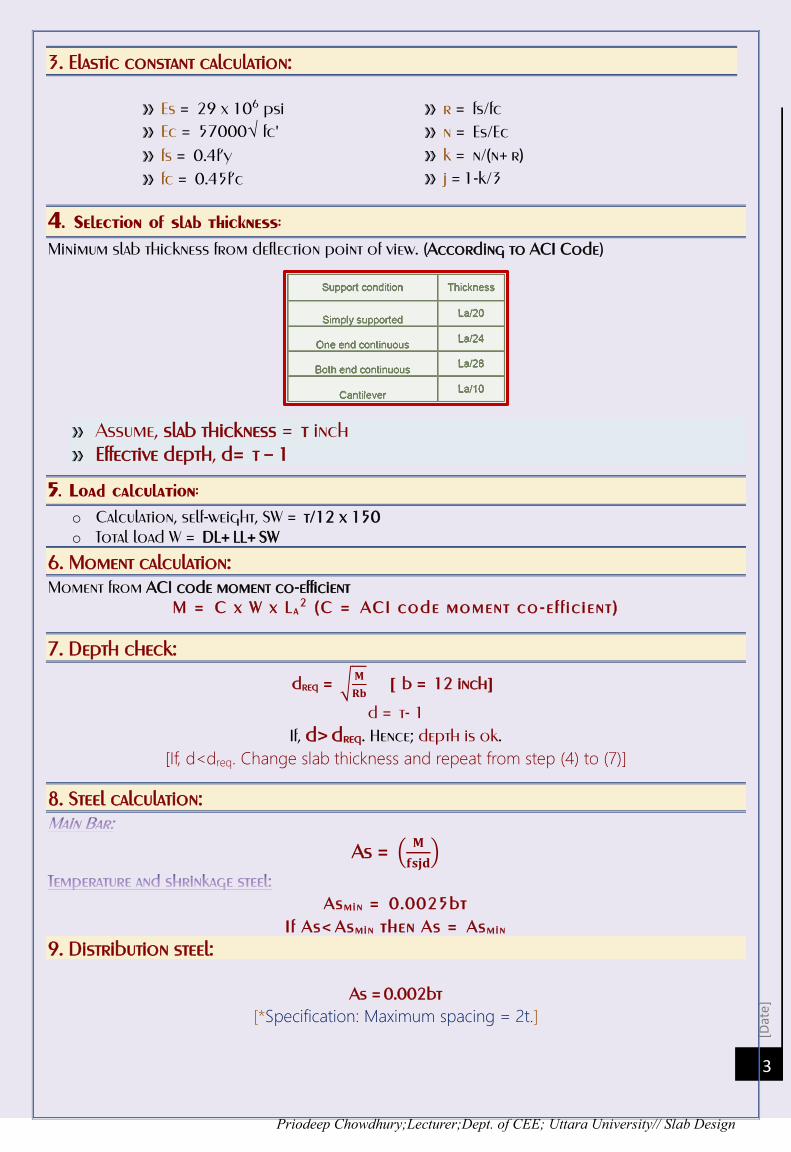
3. Elastic constant calculation:
» Es = 29 x 106 psi » Ec = 57000√ fc'
» fs = 0.4f’y » fc = 0.45f’c
» r = fs/fc » n = Es/Ec » k = n/(n+ r) » j = 1-k/3
4. Selection of slab thickness: Minimum slab thickness from deflection point of view. (According to ACI Code)
» Assume, slab thickness = t inch » Effective depth, d= t – 1
5. Load calculation: o Calculation, self-weight, SW = t/12 x 150 o Total load W = DL+ LL+ SW
6. Moment calculation: Moment from ACI code moment co-efficient
M = C x W x L a2 (C = ACI code moment co-e f f ic ient )
7. Depth check:
dreq = √𝐌
𝐑𝐛 [ b = 12 inch]
d = t- 1 If, d>dreq. Hence; depth is ok.
[If, d<dreq. Change slab thickness and repeat from step (4) to (7)]
8. Steel calculation:
As = (𝐌
𝐟𝐬𝐣𝐝)
Asmin = 0.0025bt I f As< Asmin then As = Asmin
9. Distribution steel:
As =0.002bt [*Specification: Maximum spacing = 2t.]

[Date]
Priodeep Chowdhury;Lecturer;Dept. of CEE; Uttara University// Slab Design
4
One way slab design formulae Method: Ultimate Strength Design (U S D)
1. Design data: Mentioned as above 2. Condition: Lb/La> 2 3. Elastic constant calculation:
If f’c= 4000 psi then β1 = 0.85
If f’c> 4000 psi then β1 = 0.8
Balance steel ratio –
4. Selection of slab thickness: Mentioned as above. 5. Load calculation: DL = Dead load (including self-weight) LL = Live load Total load, W = 1.4 x (DL+ SW) + 1.7 x LL 6. Moment calculation: Moment from ACI code moment co-efficient
M = C x W x La2
C = ACI code moment co- efficient. 7. Depth check:
If d > dreq; Depth is OK. If d < dreq; increase slab thickness.
8. Steel calculation:
9. Temperature and shrinkage steel: If f’y= 50000 psi then, Asmin = 0.002bt If f’y=60,000 Asmin = 0.0018bt
If f’y> 60000 psi then Asmin = 0.0018 x 60000 x bt/fy

[Date]
Priodeep Chowdhury;Lecturer;Dept. of CEE; Uttara University// Slab Design
5
Two way slab design formulae Method: Ultimate Strength Design (U S D)
1. Selection of slab thickness: Minimum slab thickness, tmin= 2(La + Lb) / 180 inch Assume slab thickness = t Effective depth in short direction; dsor = t-1 inch Effective depth in long direction; dlon = t –1.5 inch
2. Load calculation: Total load W = DL + LL + SW (Self weight) [ For WSD] Total load W = DL x 1.4 + LL x 1.7 + SW x 1.4 (Self weight) [ For USD]
3. Moment calculation: Panel ratio, m = La/Lb
(a) Negative moment at continuous edges: Maneg = Caneg x W x La2 Mbneg = Cbneg x W x Lb2 Caneg, Cbneg = Co- efficient for negative moments in slabs from panel ratio and support condition.
(b) Positive moment at mid span:
Ma.pos.dl = Capdl x DL x La2 Ma.pos.ll = Capll x LL x La2
Ma.pos.tot = Mapos.dl + Mapos.ll Mb.pos.dl = Cbpdl x DL x Lb2 Mb.pos.ll = Cbpll x LL x Lb2
Mb.pos.tot = Mbpos.dl + Mbpos.ll »» Ca.dl, Cbdl = Co- efficient for dead load positive moments.
»» Ca.ll, Cbll = Co- efficient for live load positive moments.
(c) Negative moments at discontinuous ends: Ma.neg = 1/3 x Mapos.tot Mb.neg = 1/3 x Mb.pos.tot 4. Depth check: Find Mmax
[Date]
Priodeep Chowdhury;Lecturer;Dept. of CEE; Uttara University// Slab Design
6
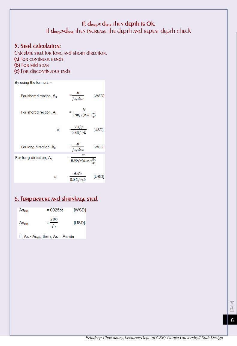
If, dreq.<dsor then depth is Ok.
If dreq.>dsor then increase the depth and repeat depth check 5. Steel calculation: Calculate steel for long and short direction. (a) For continuous ends (b) For mid span (c) For discontinuous ends
6. Temperature and shrinkage steel


![Ahmad Omar', · ACI code [3] permits opening of any size if it can be shown by analysis that the slab is safe for service loads. Coefficients method is permitted in BNBC code [2]](https://static.fdocuments.us/doc/165x107/5f2d20e8b9262706d83fa122/ahmad-omar-aci-code-3-permits-opening-of-any-size-if-it-can-be-shown-by-analysis.jpg)