Skytech 1001 - Installation and Operation Instructionsskytechpg.com/skytech/assets/File/1001-A...
6
MODEL: 1001 - A INSTALLATION AND OPERATION INSTRUCTIONS IF YOU CANNOT READ OR UNDERSTAND THESE INSTALLATION INSTRUCTIONS DO NOT ATTEMPT TO INSTALL OR OPERATE INTRODUCTION The transmitter operates on a 12V (A23) battery that is included. Install the 12V battery sup- plied with the unit into the battery compartment. It is recommended that ALKALINE batteries always be used for this product. Be sure the batteries are installed with the (+) and (-) ends facing the correct direction. The LED signal light should illuminate when either the ON or OFF button is pressed. If the signal light does not illuminate, check the position of the transmitter’s battery, and if the bat- tery is fully charged. TRANSMITTER REV 4/15/11 Page 1 This remote control system was developed to provide safe, reliable, user-friendly remote control system for gas heating appliances. The system can be operated manually from the transmitter. ON OFF FRONT BACK SIGNAL LIGHT ON/OFF BUTTONS BATTERY COMPARTMENT RECEIVER Install the (4) AA-size batteries supplied with the unit. It is recommended that ALKALINE batteries always be used for this product. Be sure the batteries are installed with the (+) and (-) ends facing the correct direction. ON • : will manually turn on the appliance. REMOTE • : will allow use of handheld transmitter. If the system does not respond to the transmitter on initial use, check the battery positions in the remote. If that does not work, see the SECURITY CODE section. OFF • : will disable the remote receiver. It is suggested that the slide switch be placed in the OFF position if you will • be away from your home for an extended period of time. REMOTE ON OFF LEARN Requires 4-AA 1.5V alkaline batteries Learning button Remote Receiver Battery cover slides on/off Slide Switch ON REMOTE OFF The remote receiver has a 3-position slide switch for selecting the mode of operation ON/REMOTE/OFF Skytech 1001-A
Transcript of Skytech 1001 - Installation and Operation Instructionsskytechpg.com/skytech/assets/File/1001-A...
MODEL: 1001 - AINSTALLATION AND OPERATION INSTRUCTIONS
IF YOU CANNOT READ OR UNDERSTAND THESE INSTALLATION INSTRUCTIONS DO NOT ATTEMPT TO INSTALL OR OPERATE
INTRODUCTION
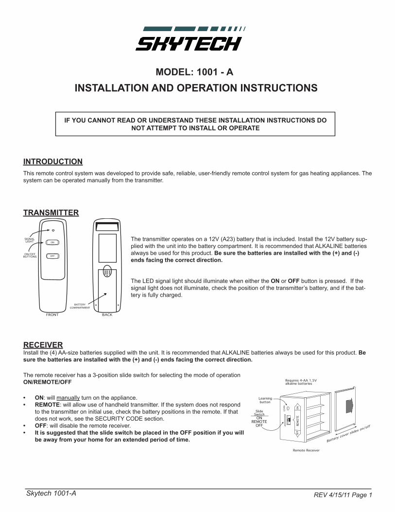
The transmitter operates on a 12V (A23) battery that is included. Install the 12V battery sup-plied with the unit into the battery compartment. It is recommended that ALKALINE batteries always be used for this product. Be sure the batteries are installed with the (+) and (-) ends facing the correct direction.
The LED signal light should illuminate when either the ON or OFF button is pressed. If the signal light does not illuminate, check the position of the transmitter’s battery, and if the bat-tery is fully charged.
TRANSMITTER
REV 4/15/11 Page 1
This remote control system was developed to provide safe, reliable, user-friendly remote control system for gas heating appliances. The system can be operated manually from the transmitter.
ON
OFF
FRONT BACK
SIGNALLIGHT
ON/OFFBUTTONS
BATTERYCOMPARTMENT
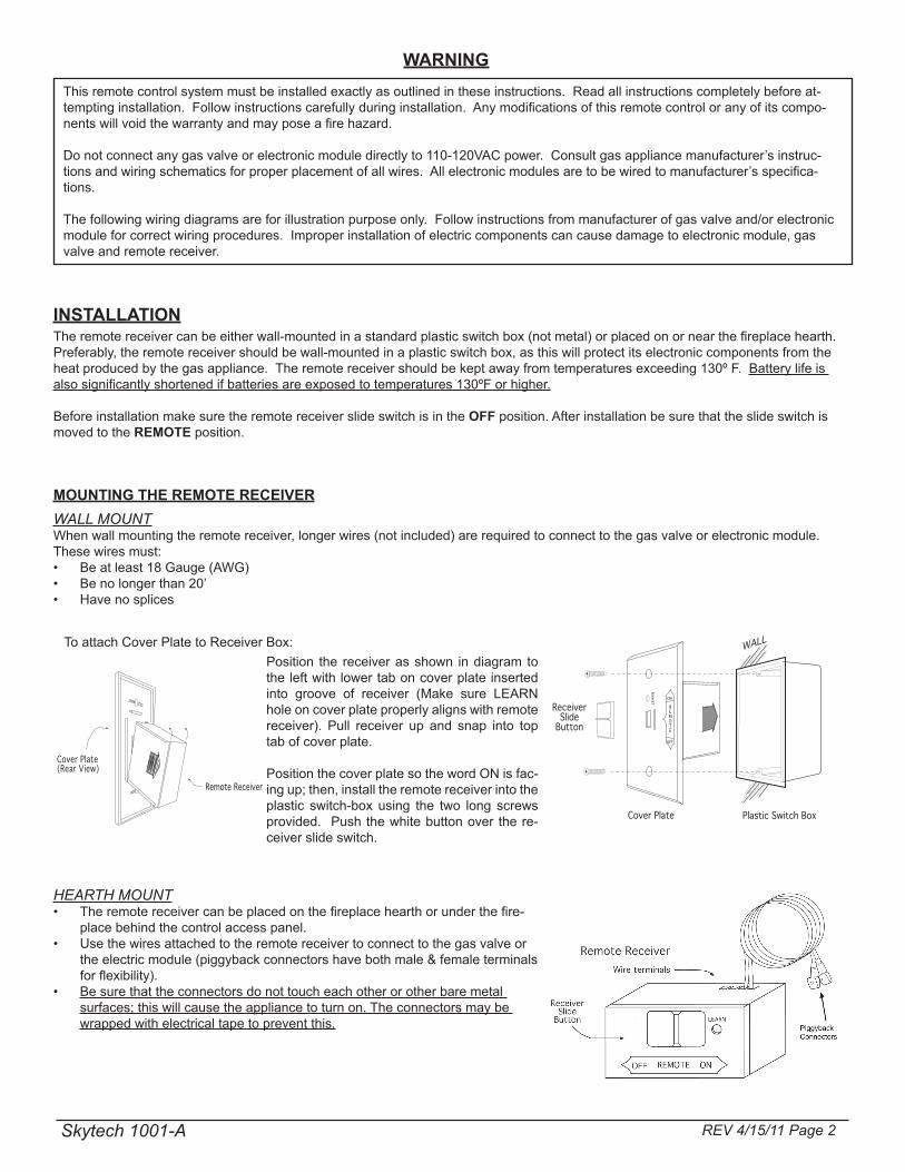
RECEIVERInstall the (4) AA-size batteries supplied with the unit. It is recommended that ALKALINE batteries always be used for this product. Be sure the batteries are installed with the (+) and (-) ends facing the correct direction.
ON• : will manually turn on the appliance.REMOTE• : will allow use of handheld transmitter. If the system does not respond to the transmitter on initial use, check the battery positions in the remote. If that does not work, see the SECURITY CODE section. OFF• : will disable the remote receiver.It is suggested that the slide switch be placed in the OFF position if you will •be away from your home for an extended period of time.
REMO
TEON
OFF
LEAR
N
Requires 4-AA 1.5Valkaline batteries
Learning button
Remote Receiver
Battery cover slides on/off
SlideSwitchON
REMOTEOFF
The remote receiver has a 3-position slide switch for selecting the mode of operation ON/REMOTE/OFF
Skytech 1001-A
INSTALLATIONThe remote receiver can be either wall-mounted in a standard plastic switch box (not metal) or placed on or near the fireplace hearth. Preferably, the remote receiver should be wall-mounted in a plastic switch box, as this will protect its electronic components from the heat produced by the gas appliance. The remote receiver should be kept away from temperatures exceeding 130º F. Battery life is also significantly shortened if batteries are exposed to temperatures 130ºF or higher.
Before installation make sure the remote receiver slide switch is in the OFF position. After installation be sure that the slide switch is moved to the REMOTE position.
MOUNTING THE REMOTE RECEIVER
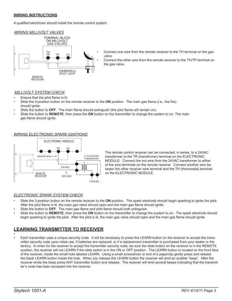
Position the receiver as shown in diagram to the left with lower tab on cover plate inserted into groove of receiver (Make sure LEARN hole on cover plate properly aligns with remote receiver). Pull receiver up and snap into top tab of cover plate.
Position the cover plate so the word ON is fac-ing up; then, install the remote receiver into the plastic switch-box using the two long screws provided. Push the white button over the re-ceiver slide switch.
Remote Receiver
Cover Plate(Rear View)
To attach Cover Plate to Receiver Box:
REV 4/15/11 Page 2
REMOTE
ON
OFF
LEA
RNWALL
Plastic Switch BoxCover Plate
ReceiverSlide
Button
HEARTH MOUNTThe remote receiver can be placed on the fireplace hearth or under the fire-• place behind the control access panel. Use the wires attached to the remote receiver to connect to the gas valve or • the electric module (piggyback connectors have both male & female terminals for flexibility).Be sure that the connectors do not touch each other or other bare metal • surfaces; this will cause the appliance to turn on. The connectors may be wrapped with electrical tape to prevent this.
WALL MOUNTWhen wall mounting the remote receiver, longer wires (not included) are required to connect to the gas valve or electronic module. These wires must:
Be at least 18 Gauge (AWG)• Be no longer than 20’• Have no splices•
WARNINGThis remote control system must be installed exactly as outlined in these instructions. Read all instructions completely before at-tempting installation. Follow instructions carefully during installation. Any modifications of this remote control or any of its compo-nents will void the warranty and may pose a fire hazard.
Do not connect any gas valve or electronic module directly to 110-120VAC power. Consult gas appliance manufacturer’s instruc-tions and wiring schematics for proper placement of all wires. All electronic modules are to be wired to manufacturer’s specifica-tions.
The following wiring diagrams are for illustration purpose only. Follow instructions from manufacturer of gas valve and/or electronic module for correct wiring procedures. Improper installation of electric components can cause damage to electronic module, gas valve and remote receiver.
Skytech 1001-A
ELECTRONIC SPARK SYSTEM CHECKSlide the 3-position button on the remote receiver to the • ON position. The spark electrode should begin sparking to ignite the pilot. Afterthepilotflameislit,themaingasvalveshouldopenandthemaingasflameshouldignite.Slide the button to • OFF.Themaingasflameandpilotflameshouldbothextinguish.Slide the button to • REMOTE,thenpresstheON button on the transmitter to change the system to on. The spark electrode should beginsparkingtoignitethepilot.Afterthepilotislit,themaingasvalveshouldopenandthemaingasflameshouldignite.
LEARNING TRANSMITTER TO RECEIVER•
Each transmitter uses a unique security code. It will be necessary to press the LEARN button on the receiver to accept the trans-•mittersecuritycodeuponinitialuse,ifbatteriesarereplaced,orifareplacementtransmitterispurchasedfromyourdealerorthefactory.Inorderforthereceivertoacceptthetransmittersecuritycode,besuretheslidebuttononthereceiverisintheREMOTEposition;thereceiverwillnotLEARNiftheslideswitchisintheONorOFFposition.TheLEARNbuttoninlocatedonthefrontfaceof the receiver; inside the small hole labeled LEARN. Using a small screwdriver or end of a paperclip gently press and release the black LEARN button inside the hole. When you release the LEARN button the receiver will emit an audible “beep”. After the receiver emits the beep press ANY transmitter button and release. The receiver will emit several beeps indicating that the transmit-ter’s code has been accepted into the receiver.
REV 4/15/11 Page 3
WIRING ELECTRONIC SPARK IGNITIONS
ELECTRONIC MODULE
TR TH
REMOTERECEIVER
neutral wire
24VAC
hot wire
120VAC
110/24VACTransformer
Theremotecontrolreceivercanbeconnected,inseries,toa24VACtransformertotheTR(transformer)terminalontheELECTRONICMODULE.Connectthehotwirefromthe24VACtransformertoeitherofthewireterminalsontheremotereceiver.Connectanotherwirebe-tween the other receiver wire terminal and the TH (thermostat) terminal ontheELECTRONICMODULE.
WIRING INSTRUCTIONS
Aqualifiedelectricianshouldinstalltheremotecontrolsystem.
TERMINAL BLOCKON MILLIVOLTGAS VALVES
THTP TP TH
THERMOPILE/PILOT LIGHT
REMOTERECEIVER
ConnectonewirefromtheremotereceivertotheTHterminalonthegas•valve.ConnecttheotherwirefromtheremotereceivertotheTH/TPterminalon•the gas valve.
WIRING MILLIVOLT VALVES
MILLIVOLT SYSTEM CHECKEnsurethatthepilotflameislit.•Slide the 3-position button on the remote receiver to the • ONposition.Themaingasflame(i.e.,thefire)should ignite. Slide the button to • OFF.Themainflameshouldextinguish(thepilotflamewillremainon).Slide the button to • REMOTE,thenpresstheON button on the transmitter to change the system to on. The main gasflameshouldignite.
Skytech 1001-A
FCC REQUIREMENTSNOTE: THE MANUFACTURER IS NOT RESPONSIBLE FOR ANY RADIO OR TV INTERFERENCE CAUSED BY UNAUTHORIZED MODI-
FICATIONS TO THE EQUIPMENT. SUCH MODIFICATIONS COULD VOID THE USER’S AUTHORITY TO OPERATE THE EQUIPMENT
For Technical Service, call: U.S. INQUIRIES888/672-8929 or 260/459-1703
Web site: www.skytechsystem.com
CANADIAN INQUIRIES877/472-3923
MANUFACTURED EXCLUSIVELY FOR SKYTECH II, INC
REV 4/15/11 Page 4
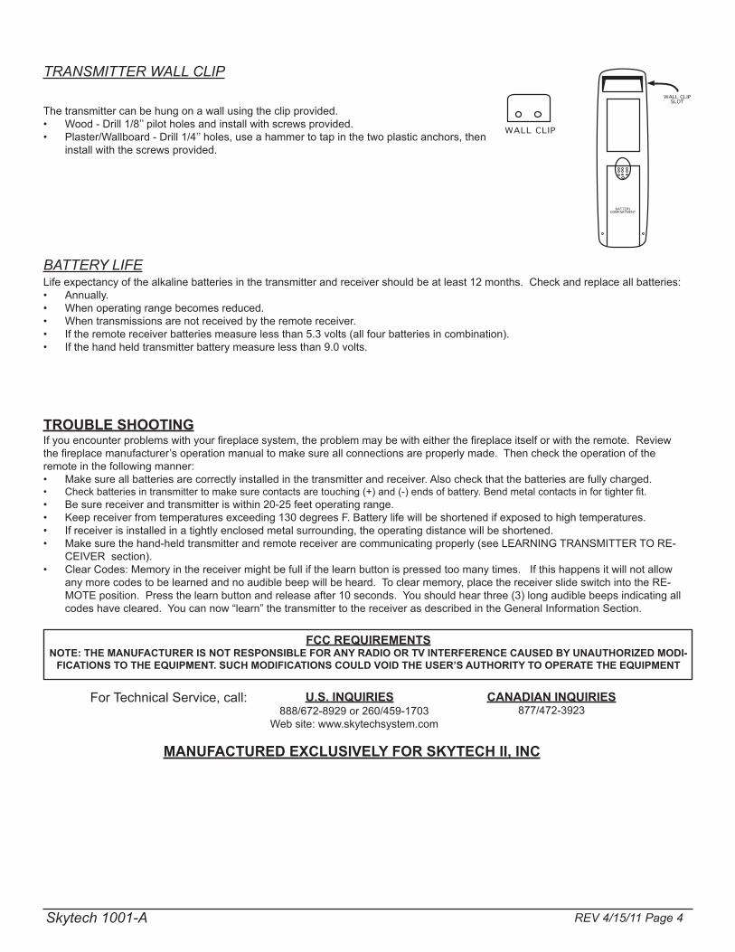
TRANSMITTER WALL CLIP
The transmitter can be hung on a wall using the clip provided.Wood - Drill 1/8’’ pilot holes and install with screws provided.•Plaster/Wallboard - Drill 1/4’’ holes, use a hammer to tap in the two plastic anchors, then •install with the screws provided.
WALL CLIPSLOT
WALL CLIP
BATTERYCOMPARTMENT
BATTERY LIFELife expectancy of the alkaline batteries in the transmitter and receiver should be at least 12 months. Check and replace all batteries:
Annually.•When operating range becomes reduced.•When transmissions are not received by the remote receiver.•If the remote receiver batteries measure less than 5.3 volts (all four batteries in combination).•If the hand held transmitter battery measure less than 9.0 volts.•
TROUBLE SHOOTINGIfyouencounterproblemswithyourfireplacesystem,theproblemmaybewitheitherthefireplaceitselforwiththeremote.Reviewthefireplacemanufacturer’soperationmanualtomakesureallconnectionsareproperlymade.Thenchecktheoperationoftheremote in the following manner:
Make sure all batteries are correctly installed in the transmitter and receiver. Also check that the batteries are fully charged.•Checkbatteriesintransmittertomakesurecontactsaretouching(+)and(-)endsofbattery.Bendmetalcontactsinfortighterfit.•Be sure receiver and transmitter is within 20-25 feet operating range.•Keep receiver from temperatures exceeding 130 degrees F. Battery life will be shortened if exposed to high temperatures.•If receiver is installed in a tightly enclosed metal surrounding, the operating distance will be shortened.•Makesurethehand-heldtransmitterandremotereceiverarecommunicatingproperly(seeLEARNINGTRANSMITTERTORE-•CEIVERsection).Clear Codes: Memory in the receiver might be full if the learn button is pressed too many times. If this happens it will not allow •anymorecodestobelearnedandnoaudiblebeepwillbeheard.Toclearmemory,placethereceiverslideswitchintotheRE-MOTEposition.Pressthelearnbuttonandreleaseafter10seconds.Youshouldhearthree(3)longaudiblebeepsindicatingallcodeshavecleared.Youcannow“learn”thetransmittertothereceiverasdescribedintheGeneralInformationSection.
Skytech 1001-A
Limited Lifetime Warranty
SKYTECH II warrants the SKYTECH REMOTE CONTROL SYSTEM for a Limited Lifetime of the original owner of this system. This warranty is not transferable to another person it is for the original purchaser of the
product. Should any part fail because of defective workmanship or material from the original date of purchase. SKYTECH II will repair or, at SKYTECH II option, replace the defective parts.
Replacement parts will be available at no charge for the first (5) five years of this warranty, and will be
available at market cost for the Lifetime of the product to that original owner. If SKYTECH II does not have the parts for an individual model, then a replacement SYSTEM will be provided. At no charge for the first (5) five
years and sold at market cost for the Lifetime of that product to the original owner.
The Owner must provide a bill of sale, cancelled check, or payment record should be kept to verify purchase date and establish warranty period. Travel, diagnostic cost, service labor to repair the defective SYSTEM, and freight charges on warranty parts to and from the factory will be the responsibility of the owner. SKYTECH will
not be responsible for labor charges and/or damage incurred in installation, repair, replacement, or for incidental or consequential damages. Batteries and any damage caused by them are not covered by them are
not covered by this warranty.
This warranty does not cover claims, which do not involve defective workmanship or materials.
Damage to the SYSTEM caused by accident, misuse, abuse, or installation error, whether performed by a contractor, Service Company, or owner, is not covered by this warranty. Modification of the SKYTECH product
will void this warranty.
IN NO EVENT SHALL SKYTECH BE LIABLE FOR INCIDENTAL AND CONSEQUENTIAL INCLUDING THE IMPLIED WARRANTIES OF MERCHANTABILITY AND FITNESS, ARE LIMITED TO THE DURATION OF THIS WRITTEN
WARRANTY. THIS WARRANTY SUPERSEDES ALL OTHER ORAL OR WRITTEN WARRANTIES.
Some States do not allow the exclusion or limitation of incidental and consequential damages or limitation on how long an implied warranty lasts, so the above limitation may not apply to you. This warranty gives you
specific rights and you may have other rights, which vary from state, province, and nation.
How to Obtain Service: Contact SKYTECH II or your SKYTECH Dealer direct with the following information:
- Name, Address, Telephone Number of Owner - Date of Purchase, Proof of Purchase
- Model Name, Date Code Any relevant information or circumstances, e.g., installation, mode of operation when defect was noted.
Warranty claim process will start with all of this information. SKYTECH will reserve the right to physically
inspect the product for defects, by authorized representatives. Detach at this line for return to: Skytech II 9230 Conservation Way, Fort Wayne, IN 46809 Telephone: (888) 672-8929 Purchase Date: Model: Date Code: Purchased From: Date: Customer Name Number of Santa’s Helpers Address City State/Prov. Zip/Postal Code Credit Card Number Expiring Date (Visa and MasterCard Only) See other side for a special offer for all Remote control Customers

Santa’s Helper Exclusive offer to Skytech Remote Control Owners
This special offer is only provided to customers of Skytech II, Inc. that have purchased a remote control for their Hearth Product. This remote control system can be used for any 110Volt appliance, but perfect your Christmas Tree Lights or any other appliance that is difficult to reach or plug in. Simply plug the receiver into your wall outlet and your appliance into the receiver, push the ON button on the transmitter and you are in business. It’s that easy.
The list price of $29.95 for the Santa’s Helper has been cut almost in half to $15.00 USD for this exclusive offer. Shipping and handling of $5.00 $USD should be added. Send your check, money order or your Visa / MasterCard number, with Expiration Date to our office, along with the warranty information from your remote control for your Hearth Product. You can send this via mail, fax, or e-mail. Skytech II, Inc. 9230 Conservation Way Fort Wayne, IN 46809 1 (888) 672-8929 1 (888) 672-8024 Fax [email protected] e-mail