

SKIL Power Tools Operating Instructions - CARiD.com
14
IMPORTANT: Read Before Using Operating/Safety Instructions 7302
Transcript of SKIL Power Tools Operating Instructions - CARiD.com

Work area safetyKeep work area clean and well lit. Clutteredor dark areas invite accidents.
Do not operate power tools in explosiveatmospheres, such as in the presence offlammable liquids, gases or dust. Powertools create sparks which may ignite the dustor fumes.
Keep children and bystanders away whileoperating a power tool. Distractions cancause you to lose control.
Electrical safetyPower tool plugs must match the outlet.Never modify the plug in any way. Do notuse any adapter plugs with earthed(grounded) power tools. Unmodified plugsand matching outlets will reduce risk of electricshock.
Avoid body contact with earthed or groundedsurfaces such as pipes, radiators, rangesand refrigerators. There is an increased riskof electric shock if your body is earthed orgrounded.
Do not expose power tools to rain or wetconditions. Water entering a power tool willincrease the risk of electric shock.
Do not abuse the cord. Never use the cordfor carrying, pulling or unplugging the powertool. Keep cord away from heat, oil, sharpedges or moving parts. Damaged or entangledcords increase the risk of electric shock.
When operating a power tool outdoors,use an extension cord suitable for outdooruse. Use of a cord suitable for outdoor usereduces the risk of electric shock.
If operating the power tool in damp locationsis unavoidable, use a Ground Fault CircuitInterrupter (GFCI) protected supply. Use ofan GFCI reduce the risk of electric shock.
Personal safetyStay alert, watch what you are doing anduse common sense when operating a
power tool. Do not use a power tool whileyou are tired or under the influence of drugs,alcohol or medication. A moment of inattentionwhile operating power tools may result inserious personal injury.
Use personal protective equipment. Alwayswear eye protection. Protective equipmentsuch as dust mask, non-skid safety shoes, hardhat, or hearing protection used for appropriateconditions will reduce personal injuries.
Prevent unintentional starting. Ensure theswitch is in the off-position beforeconnecting to power source and / or batterypack, picking up or carrying the tool.Carrying power tools with your finger on theswitch or energizing power tools that have theswitch on invites accidents.
Remove any adjusting key or wrench beforeturning the power tool on. A wrench or akey left attached to a rotating part of thepower tool may result in personal injury.
Do not overreach. Keep proper footing andbalance at all times. This enables bettercontrol of the power tool in unexpectedsituations.
Dress properly. Do not wear loose clothingor jewelry. Keep your hair, clothing andgloves away from moving parts. Looseclothes, jewelry or long hair can be caught inmoving parts.
If devices are provided for the connectionof dust extraction and collection facilities,ensure these are connected and properlyused. Use of dust collection can reduce dust-related hazards.
Power tool use and careDo not force the power tool. Use thecorrect power tool for your application. Thecorrect power tool will do the job better andsafer at the rate for which it was designed.
Do not use the power tool if the switch doesnot turn it on and off. Any power tool thatcannot be controlled with the switch isdangerous and must be repaired.
Read all safety warnings and instructions. Failure to follow the warningsand instructions may result in electric shock, fire and/or serious injury.
SAVE ALL WARNINGS AND INSTRUCTIONS FOR FUTURE REFERENCE
The term “power tool” in the warnings refers to your mains-operated (corded) power tool orbattery-operated (cordless) power tool.
! WARNING
General Power Tool Safety Warnings
-2-

-3-
Disconnect the plug from the power sourceand/or the battery pack from the power toolbefore making any adjustments, changingaccessories, or storing power tools. Suchpreventive safety measures reduce the risk ofstarting the power tool accidentally.
Store idle power tools out of the reach ofchildren and do not allow personsunfamiliar with the power tool or theseinstructions to operate the power tool.Power tools are dangerous in the hands ofuntrained users.
Maintain power tools. Check for misalignmentor binding of moving parts, breakage ofparts and any other condition that mayaffect the power tool’s operation. Ifdamaged, have the power tool repairedbefore use. Many accidents are caused by
poorly maintained power tools.
Keep cutting tools sharp and clean. Properlymaintained cutting tools with sharp cuttingedges are less likely to bind and are easier tocontrol.
Use the power tool, accessories and toolbits etc. in accordance with these instructions,taking into account the working conditionsand the work to be performed. Use of thepower tool for operations different from thoseintended could result in a hazardous situation.
ServiceHave your power tool serviced by a qualifiedrepair person using only identicalreplacement parts. This will ensure that thesafety of the power tool is maintained.
Safety Rules for Orbital Sanders
Hold power tools by insulated grippingsurfaces when performing an operationwhere the cutting tool may contact hiddenwiring or its own cord. Contact with a "live"wire will make exposed metal parts of the tool"live" and shock the operator.
Unplug the sander before changingaccessories. Accidental start-ups may occurif sander is plugged in while changing anaccessory.
Use clamps or another practical way tosecure and support the workpiece to astable platform. Holding the work by handor against your body leaves it unstable andmay lead to loss of control.
Your tool is equipped with a dustcanister, empty it frequently, aftercompletion of sanding and before storingthe sander. Be extremely careful of dustdisposal, materials in fine particle form maybe explosive. Do not throw sanding dust onan open fire. Combustion from mixture ofvarnishes, lacquers, polyurethane, oil orwater with dust particles can occur if there isa static discharge, spark introduced in thebox, or excessive heat.
Always wear eye protection and a dustmask for dusty applications and whensanding overhead. Sanding particles can beabsorbed by your eyes and inhaled easilyand may cause health complications.
Use special precautions when sandingchemically pressure treated lumber, paintthat may be lead based, or any othermaterials that may contain carcinogens. Asuitable breathing respirator and protectiveclothing must be worn by all persons enteringthe work area. Work area should be sealedby plastic sheeting and persons notprotected should be kept out until work areais thoroughly cleaned.
Do not wet sand with this sander. Liquidsentering the motor housing is an electricalshock hazard.
Do not use sandpaper intended for largersanding pads. Larger sandpaper will extendbeyond the sanding pad causing snagging,tearing of the paper or kick-back. Extra paperextending beyond the sanding pad can alsocause serious lacerations.

-4-
Additional Safety Warnings
GFCI and personal protection devices likeelectrician’s rubber gloves and footwear willfurther enhance your personal safety.
Do not use AC only rated tools with a DCpower supply. While the tool may appear towork, the electrical components of the ACrated tool are likely to fail and create a hazardto the operator.
Keep handles dry, clean and free from oiland grease. Slippery hands cannot safelycontrol the power tool.
Develop a periodic maintenance schedulefor your tool. When cleaning a tool becareful not to disassemble any portion ofthe tool since internal wires may bemisplaced or pinched or safety guard returnsprings may be improperly mounted.Certain cleaning agents such as gasoline,carbon tetrachloride, ammonia, etc. maydamage plastic parts.
Risk of injury to user. The power cord must onlybe serviced by a Skil Factory Service Center orAutho rized Skil Service Station.
Some dust created by powersanding, sawing, grinding,
drilling, and other construction activitiescontains chemicals known to cause cancer,birth defects or other reproductive harm.Some examples of these chemicals are:
• Lead from lead-based paints,
• Crystalline silica from bricks and cement andother masonry products, and
• Arsenic and chromium from chemically-treated lumber.
Your risk from these exposures varies,depending on how often you do this type ofwork. To reduce your exposure to thesechemicals: work in a well ventilated area, andwork with approved safety equipment, such asthose dust masks that are specially designedto filter out microscopic particles.
! WARNING

-5-
IMPORTANT: Some of the following symbols may be used on your tool. Please study themand learn their meaning. Proper interpretation of these symbols will allow you to operate thetool better and safer.
Symbol Name Designation/Explanation
V Volts Voltage (potential)
A Amperes Current
Hz Hertz Frequency (cycles per second)
W Watt Power
kg Kilograms Weight
min Minutes Time
s Seconds Time
Diameter Size of drill bits, grinding wheels, etc.
n0 No load speed Rotational speed, at no load
n Rated speed Manufacturers rated speed
.../min Revolutions or reciprocation Revolutions, strokes, surface speed,
per minute orbits etc. per minute
0 Off position Zero speed, zero torque...
1, 2, 3, ... Selector settings Speed, torque or position settings.
I, II, III, Higher number means greater speed
Infinitely variable selector with off Speed is increasing from 0 setting
Arrow Action in the direction of arrow
Alternating current Type or a characteristic of current
Direct current Type or a characteristic of current
Alternating or direct current Type or a characteristic of current
Class II construction Designates Double Insulated
Construction tools.
Earthing terminal Grounding terminal
Warning symbol Alerts user to warning messages
Li-ion RBRC seal Designates Li-ion battery recycling
program
Ni-Cad RBRC seal Designates Ni-Cad battery recycling
program
Read manual symbol Alerts user to read manual
Wear eye protection symbol Alerts user to wear eye protection
Symbols
0

-6-
This symbol designates that this tool is listed by Underwriters Laboratories.
This symbol designates that this tool is listed by the Canadian StandardsAssociation.
This symbol designates that this tool is listed by the Canadian StandardsAssociation, to United States and Canadian Standards.
This symbol designates that this tool complies to NOM Mexican Standards.
This symbol designates that this tool is listed by Underwriters Laboratories,to United States and Canadian Standards.
This symbol designates that this tool is listed by the Intertek TestingServices, to United States and Canadian Standards.
Symbols (continued)
IMPORTANT: Some of the following symbols may be used on your tool. Please study themand learn their meaning. Proper interpretation of these symbols will allow you to operate thetool better and safer.

-7-
Functional Description and Specifications
Disconnect the plug from the power source before making anyassembly, adjustments or changing accessories. Such preventive safety
measures reduce the risk of starting the tool accidentally.
! WARNING
Multi-Finishing Sander
FIG. 1
PAD/PLATEUNLOCKBUTTON
ATTACHMENTSUPPORTPLATE
EXTENSIONPLATE
Model number 7302
Voltage rating 120 V 60Hz
Amperage rating 1.2 A
No load speed n0 12,000/min
MICROFILTERDUST CANISTER
CORD
MICROFILTER
RUBBERIZEDGRIP
DUSTSEALEDSWITCH
PRESSURECONTROLINDICATORLIGHTS
VENTILATIONOPENINGS
VENTILATIONOPENINGS

Disconnect the plug fromthe power source before
making any assembly, adjustments orchanging accessories. Such preventivesafety measures reduce the risk of startingthe tool accidentally.
BACKING PAD REMOVAL/INSTALLATIONYour Multi-Finishing sander is equipped with ahook- and-loop rubber backing pad which may
be removed and attached without the need ofaddi tional tools.
To remove, press the pad/plate unlock buttonand pull the backing pad free from the sander (Fig. 2.)
To install, engage rear of backing pad underlatched in tool’s recess and press front ofbacking pad in place until it engages with a"Click" sound (Fig. 2).
Assembly
! WARNING
PAD/PLATEUNLOCKBUTTON
BACKINGPAD
ROTATING BACKING PADFor maximum use of abrasive, rotate pad 120degrees when tip of abrasive becomes wornFig. 3).)
FIG. 3
INSTALLING SANDING SHEETSYour sander uses hook-and-loop backedsandpaper, which firmly grips the backing padwhen applied with moderate pressure.
To change, mere ly peel off the old sandpaper,remove dust from the backing pad if necessary,and press the new sandpaper in place. Be sureto align the sanding sheet holes with the holesin the backing pad to allow the dust extractionsystem to function (Fig. 4).
After considerable use the backing pad surfacewill become worn, and the backing pad must bereplaced when it no longer offers a firm grip. Ifyou are experiencing premature wear of theback ing pad facing, decrease the amount of
pressure you are applying during operation ofthe tool.
FIG. 4
LATCHESFIG. 2
-8-
-9-
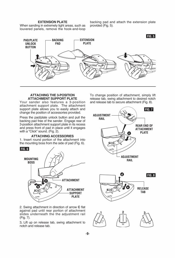
EXTENSION PLATEWhen sanding in extremely tight areas, such aslouvered panels, remove the hook-and-loop
backing pad and attach the extension plateprovided (Fig. 5).
FIG. 5PAD/PLATEUNLOCKBUTTON
BACKINGPAD
EXTENSIONPLATE
ATTACHING THE 3-POSITION ATTACHMENT SUPPORT PLATE
Your sander also features a 3-positionattachment support plate. The attachmentsupport plate allows you to easily attach andchange the position of accessories provided.
Press the pad/plate unlock button and pull thebacking pad free of the sander. Engage rear of3-position attachment support plate in its recessand press front of pad in place until it engageswith a "Click" sound. (Fig. 2).
ATTACHING ACCESSORIES 1. Insert round portion of the attachment intothe mounting boss from the side of pad (Fig. 6).
2. Swing attachment in direction of arrow C flatagainst pad until rear portion of attachmentslides underneath the the adjustment rail (Fig. 7).
3. Lift up on release tab, swing attachment tonotch and release tab.
To change position of attachment, simply liftrelease tab, swing attachment to desired notchand release tab to secure attachment (Fig. 8).
ADJUSTMENTRAIL
REAR END OFATTACHMENT
PLATE
ADJUSTMENTRAIL
FIG. 7
FIG. 8
RELEASETAB
ATTACHMENT
MOUNTINGBOSS
FIG. 6
ATTACHMENTSUPPORTPLATE

-10-
ROCKER “ON/OFF” SWITCHTO TURN THE TOOL "ON" depress the dust-protected switch to the number “I” position(Fig. 1).
TO TURN THE TOOL "OFF": depress switchto the number “0” position.
Always hold the sander off the work whenturning the switch “ON” or “OFF”. Contact thework with the tool after sander has reached itsfull speed and remove it from the work beforeturning the switch “OFF”. Operating in thismanner will prolong switch and motor life andwill greatly increase the quality of your work.
PRESSURE CONTROLYour tool is equipped with pressure controlindicator lights. The indicator lights will let youknow if you are applying the proper amount ofpressure during operation. If the greenindicator lights are illuminated you are applyingthe correct amount of pressure. If the redindicator light illuminates you are applying toomuch pressure and you need to apply lesspressure (Fig. 9).
Pressure control feature is intended for usewith standard Delta backing pad.
Operating Instructions
MICROFILTER DUST CANISTERThe integral dust extraction system collectssanding dust in canister supplied with yoursander. For maximum efficiency, the dustcanister should be emptied frequently duringoperation.
Your tool is equipped with adust canister, empty it
frequently, after completion of sanding andbefore storing the sander. Be extremelycareful of dust disposal, materials in fineparticle form may be explosive. Do not throwsanding dust on an open fire. Combustionfrom mixture of varnishes, lacquers,polyurethane, oil or water with dust particlescan occur if there is a static discharge, sparkintroduced in the box, or excessive heat.
REMOVING AND INSTALLING DUST CANISTER
To remove dust canister, simply pull away fromthe tool (Fig. 9).
To install dust canister, align dust port withhole in canister and push canister onto tool.
CLEANING AND EMPTYINGTHE DUST CANISTER
Knock excess dust out of the microfilter, orremove dust with your fingers or a soft brush.You may notice that all the dust may notcome out of the canister. This will not affectsanding performance but will reduce dustcollection efficiency.
NOTE: Do not wash the micro filter with soapand water. Dust may become more firmlylodged in the pores, which will reduce dustcollection, and damage the micro filter.
! WARNING
FIG. 9
DUST PORTMICROFILTERDUST CANISTER
MICROFILTER
EXCESSIVEPRESSURE
OPTIMALPRESSURE

-11-
This tool is particularly suitable for one hand edoperation, and access to corners and edgesthat are otherwise difficult to reach and requirehand sanding. Profiles and grooves may be fin -ished using the tip or edge of the selectedattachment, which should occasionally berotated during use to distribute the wear on theattachment and backing pad surface.
Always be certain that smaller workpieces aresecurely fastened to a bench or other support.Larger panels may be held in place by hand ona bench or sawhorses.
SANDING: Open-coat aluminum oxide sandingsheets are recommended for most wood ormetal sand ing applications, as this syntheticmaterial cuts quickly and wears well. Someapplications, such as metal finishing orcleaning, require spe cial abrasive pads whichare available from your dealer. For best results,use sanding and polishing accessories whichare of superior quality and are carefullyselected to produce professional quality resultswith your sander.
The following suggestions may be used as agen eral guide for abrasive selection, but thebest re sults will be obtained by sanding a testsample of the workpiece first.
Grit Application
Coarse For rough wood or metal sanding, and rust or old finish removal.
Medium For general wood or metal sanding
Fine For final finishing of wood, metal,plaster and other surfaces.
Extra fine For final sanding of bare wood,smoothing old paint, or preparing afinished surface for recoating.
With the workpiece firmly secured, turn tool onas described above. Contact the work with thetool after the sander has reached its full speed,and remove it from the work before switchingthe tool off. Operating your sander in thismanner will pro long switch and motor life, andgreatly increase the quality of your work.
Move the sander in long steady strokes parallel to the grain using some lateral motion to
overlap the strokes by as much as 75%. DONOT apply exces sive pressure — let the tooldo the work. Ex cessive pressure will result inpoor handling, vibration, and unwanted sandingmarks (Fig. 10).
If the surface is rough, begin with coarser gritsand then complete the surfacing with mediumand fine abra sives. To avoid uneven results, donot skip more than one grit size when goingfrom coarser to finer, and do not sand in onearea for too long. When the job is completed,gently lift the tool from the work surface andslide switch to the "OFF" position.
POLISHING: Your Multi-finishing sander maybe fit ted with optional abrasive mesh orpolishing pads to polish or remove scratches orcorrosion from metal, painted, or othersurfaces. The tool is oper ated in much thesame way as when sanding, but the followingpoints should be observed;
Use light pressure and a circular or overlappingmo tion to remove scratches and corrosion orpol ish a surface. If using a compound, use onlyas much as necessary and do not use the dustex trac tion feature.
When working in very confined areas orlouvered panels, the pad extension plateshould be used.
Clean the buffing or mesh pads with mild deter -gents and warm water. DO NOT use solvents.
Tool Tips
FIG. 10

-12-
Application Advise
Use the tool with its standard backing pad forlarge work surfaces, corners and edges (Fig. 11).
Use the tool with special sanding attachmentsfor hard to reach areas (Fig. 12).
The flexible sanding attachment is intended forrounding edged surfaces (Fig. 13a).
The flexible sanding can also be used on allrounded surfaces with a maximum diameter of10 cm (Fig. 13b).
FIG. 11
FIG. 12

-13-
ServicePreventive maintenanceperformed by unauthorized
per so n nel may result in misplacing ofinternal wires and components whichcould cause serious hazard. Werecommend that all tool service be performedby a Skil Factory Service Center or Autho rizedSkil Service Station.
TOOL LUBRICATIONYour Skil tool has been properly lubricatedand is ready to use. It is recommended thattools with gears be regreased with a specialgear lubricant at every brush change.
CARBON BRUSHESThe brushes and commutator in your toolhave been engineered for many hours ofdependable service. To maintain peakefficiency of the motor, we recommend everytwo to six months the brush es be examined.Only genuine Skil replace ment brushesspecially designed for your tool should beused.
BEARINGSAfter about 300-400 hours of operation, or atevery second brush change, the bearings
should be replaced at Skil Factory Service Center or Au thorized Skil Service Station.Bearings which become noisy (due to heavyload or very abrasive material cut ting) shouldbe replaced at once to avoid overheating ormotor failure.
CleaningTo avoid accidents alwaysdis connect the tool from
the power supply before cleaning orperforming any main tenance. The tool maybe cleaned most effectively with compresseddry air. Always wear safety gog gles whencleaning tools with compressed air.
Ventilation openings and switch levers mustbe kept clean and free of foreign matter. Donot at tempt to clean by inserting pointedobjects through openings.
Certain cleaning agentsand sol vents damage
plastic parts. Some of these are: gasoline,carbon tetrachlo ride, chlo rinated cleaningsolvents, ammonia and house hold detergentsthat contain ammonia.
! WARNING
! WARNING
Maintenance
! CAUTION
FIG. 13b
FIG. 13a

-14-
Accessories
If an extension cord isnecessary, a cord with
adequate size conductors that is capableof carrying the current necessary for yourtool must be used. This wil l preventexcessive voltage drop, loss of power oroverheating. Grounded tools must use 3-wire extension cords that have 3-prong plugsand receptacles.
NOTE: The smaller the gauge number, theheav i er the cord.
RECOMMENDED SIZES OF EXTENSION CORDS
120 VOLT ALTERNATING CURRENT TOOLS! WARNING
* (8) Attachments
* (32) Pieces of abrasives
* (1) Carrying bag
(*= standard equipment)
(**= optional accessories)
Tool’s
Ampere
Rating
Cord Size in A.W.G. Wire Sizes in mm2
3-66-88-1010-1212-16
18 16 16 14 0.75 0.75 1.5 2.518 16 14 12 0.75 1.0 2.5 4.018 16 14 12 0.75 1.0 2.5 4.016 16 14 12 1.0 2.5 4.0 —14 12 — — — — — —
25 50 100 150 15 30 60 120Cord Length in Feet Cord Length in Meters
Trouble Shooting
Read instruction manual first! Remove plug from the power source beforemaking adjustments or assembling accessories.
TROUBLE: TOOL WILL NOT STARTPROBLEM 1. Power cord is not plugged in.
2. Power source fuse or circuit breaker tripped.3. Cord damaged.4. Burned out switch.
REMEDY 1. Plug tool into power source.2. Replace fuse or reset tripped circuit breaker. (If the product repeatedly causesthe circuit or fuse to trip/blow, discontinue use immediately and have it serviced byan Authorized Skil Service Center or Service Station.)3. Inspect cord for damage. If damaged, have cord replaced by an Authorized SkilService Center or Service Station.4. Have switch replaced by an Authorized Skil Service Center or Service Station.
TROUBLE: TOOL DOES NOT COME UP TO SPEEDPROBLEM 1. Extension cord has insufficient gauge or is too long.
2. Low house voltage.
REMEDY 1. Replace with adequate extension cord (Page 14).2. Contact your electric company.
! WARNING