
ska signal processing strategy to proceed to the next phase
26
Name Designation Affiliation Date Signature Additional Authors Submitted by: W. Turner Signal Processing Domain Specialist SPDO 2011‐04‐01 Approved by: K.Cloete Project Manager SPDO 2011‐04‐01 SKA SIGNAL PROCESSING STRATEGY TO PROCEED TO THE NEXT PHASE Document number ................................................................ WP2‐040.010.030‐PLA‐001 Revision ........................................................................................................................... 1 Author................................................................................................................. W.Turner Date ................................................................................................................ 2011‐04‐01 Status ............................................................................................... Approved for release
Transcript of ska signal processing strategy to proceed to the next phase

Name Designation Affiliation Date Signature
Additional Authors
Submitted by:
W. Turner Signal Processing Domain Specialist
SPDO 2011‐04‐01
Approved by:
K.Cloete Project Manager SPDO 2011‐04‐01
SKA SIGNAL PROCESSING STRATEGY TO PROCEED TO
THE NEXT PHASE
Document number ................................................................ WP2‐040.010.030‐PLA‐001
Revision ........................................................................................................................... 1
Author ................................................................................................................. W.Turner
Date ................................................................................................................ 2011‐04‐01
Status ............................................................................................... Approved for release

WP2‐040.010.030‐PLA‐001 Revision : 1
2011‐04‐01 Page 2 of 26
DOCUMENT HISTORY
Revision Date Of Issue Engineering Change
Number
Comments
A ‐ ‐ First draft release for internal review
B ‐ ‐ Addressed comments received by K.Cloete
1 1st April 2011 First Issue
DOCUMENT SOFTWARE
Package Version Filename
Wordprocessor MsWord Word 2007 10‐WP2‐040.010.030.PLA‐001‐1_SKASPNextPhase
Block diagrams
Other
ORGANISATION DETAILS
Name SKA Program Development Office
Physical/Postal
Address
Jodrell Bank Centre for Astrophysics
Alan Turing Building
The University of Manchester
Oxford Road
Manchester, UK
M13 9PL
Fax. +44 (0)161 275 4049
Website www.skatelescope.org

WP2‐040.010.030‐PLA‐001 Revision : 1
2011‐04‐01 Page 3 of 26
TABLE OF CONTENTS
1 INTRODUCTION ............................................................................................. 6
1.1 Purpose of the document ....................................................................................................... 6
2 REFERENCES ................................................................................................ 6
3 OVERVIEW .................................................................................................. 7
3.1 SKA Phases and Milestones .................................................................................................... 7
3.1.1 Preparatory Phase ........................................................................................................... 7
3.1.2 Pre‐Construction Phase................................................................................................... 8
3.1.3 Construction, Verification, Commissioning, Acceptance, Integration & First Science ... 8
3.1.4 SKA2 Construction, Commissioning, Acceptance, Integration & First Science ............... 8
3.2 SKA Work Packages ................................................................................................................. 9
3.3 WP2.5 Digital Signal Processing ........................................................................................... 10
3.4 Signal Processing Time Line .................................................................................................. 11
3.4.1 Conceptual Design Review, CoDR ................................................................................. 11
3.4.2 System Requirements Review, SRR .............................................................................. 13
3.4.3 Preliminary Design Review, PDR ................................................................................... 13
3.4.4 Critical Design Review, CDR .......................................................................................... 14
4 GAPS IN THE CONCEPT PHASE ........................................................................ 15
4.1.1 Remote Station Beamforming Concept ........................................................................ 15
4.1.2 Reliability and Maintainability, RAM, Estimates ........................................................... 16
4.1.3 Software development and costing strategy ................................................................ 17
5 DEFINITION PHASE ...................................................................................... 17
5.1 Tools ...................................................................................................................................... 18
5.1.1 Requirements ................................................................................................................ 18
5.1.2 Document Management ............................................................................................... 18
5.1.3 Modelling ...................................................................................................................... 18
5.2 SRR Document Tree .............................................................................................................. 19
5.3 Signal Processing Requirements ........................................................................................... 20
5.4 Further Development of Concepts ....................................................................................... 20
5.4.1 Software Correlator ...................................................................................................... 20
5.4.2 Embedded Correlator ................................................................................................... 21
5.4.3 Tasks related specifically to Central Beamformer Design ............................................ 22
5.4.4 Tasks related specifically to Non Imaging processing ................................................... 23
5.5 List of Resources ................................................................................................................... 24
5.6 Estimated Contributions to Remainder of WP2 ................................................................... 26
LIST OF FIGURES
WP2‐040.010.030‐PLA‐001 Revision : 1
2011‐04‐01 Page 4 of 26
Figure 1 SKA top level phases and milestones. ....................................................................................... 7
Figure 2 SKA Work Packages ................................................................................................................... 9
Figure 3 Work Package 2 Taxonomy ..................................................................................................... 10
Figure 4 Signal processing time scales .................................................................................................. 11
Figure 5 Phases, reviews and baselines ................................................................................................ 17
Figure 6 SRR Document Tree ................................................................................................................ 19
LIST OF TABLES
Table 1 Mapping of SEMP identified deliverables to the SP CoDR document set ................................ 12
Table 2 Reliability Coverage in Concept Descriptions ........................................................................... 16
Table 3 List of Resources ....................................................................................................................... 25
Table 4 Estimated person month contributions from 1 January 2011 to 31 March 2012 ................... 26

WP2‐040.010.030‐PLA‐001 Revision : 1
2011‐04‐01 Page 5 of 26
LIST OF ABBREVIATIONS
AAVP ...................................... Aperture Array Verification Program
ASKAP .................................... Australian SKA Pathfinder
ASG ........................................ Agencies SKA Group
CoDR ...................................... Concept Design Review
DOW ....................................... Description of Work
DRM ........................................ Design Reference Mission
FP7 ......................................... Framework 7
IEAC ........................................ International Engineering Advisory Committee
MeerKAT ................................. South African pathfinder being built in the Karoo
PDR ........................................ Preliminary Design Review
PEP ......................................... Project Execution Plan
PMP ........................................ Project Management Plan
PrepSKA ................................. Preparatory Phase for the SKA
SEMP ...................................... System Engineering Management Plan
SSEC ...................................... SKA Science and Engineering Committee
SKA ......................................... Square Kilometre Array
SKA1 ....................................... Phase 1 of the SKA
SKA2 ....................................... Phase 2 of the SKA
SPDO ...................................... SKA Program Development Office
SPO ........................................ SKA Project Office
SRR ........................................ System Requirements Review
SWG ....................................... Science Working Group
UK ........................................... United Kingdom
WP .......................................... Work Packages

WP2‐040.010.030‐PLA‐001 Revision : 1
2011‐04‐01 Page 6 of 26
1 Introduction
The purpose of this document is to describe the strategy to move to the next SKA element level
engineering phase for the signal processing aspects of the project, the definition phase.
1.1 Purpose of the document
In support of the purpose of the document the following aspects are described:
High level milestones
Identify the gaps at the CoDR
Identify the activities to address gaps
Identify activities in heading towards the next review the SRR
This Signal Processing Strategy to Proceed to the Next Phase document is part of a document series
generated to provide a top down and bottom up approach in support of the Signal Processing CoDR.
This document set includes the following:
Signal Processing High Level Description
Technology Roadmap
Design Concept Descriptions
Signal Processing Requirements
Signal Processing Costs
Signal Processing Risk Register
Signal Processing Strategy to Proceed to the Next Phase
Signal Processing CoDR Review Plan
Software & Firmware Strategy
2 References
The following documents are referenced in this document.
[1] Strategy to to Proceed To The Next Phase WP2‐005.010.030‐PLA‐002, K Cloete 15th Feb
2011
[2] R.T. Schilizzi et al, ‘Project Execution Plan – Pre‐Construction Phase for the Square Kilometre
Array (SKA)’, document MGT‐001.005.005‐MP‐001, Rev K.
[3] K. Cloete et al, ‘PrepSKA FP7 Work Package 2 Project Plan’, document MGT‐040.030.002‐
PLA‐001, Rev I, dated 2011‐02‐16.
[4] T.J. Stevenson, ‘System Engineering Management Plan’, document WP2‐005.010.030‐MP‐
001, Revision F, dated 2011‐02‐15.
[5] B.Carlson, Giant Systolic Array (GSA) Correlator Concept Description
WP2‐040.050.010‐TD‐001 Rev B 11th March 2011

WP2‐040.010.030‐PLA‐001 Revision : 1
2011‐04‐01 Page 7 of 26
3 Overview
A high level overview of the SKA project and its milestones is presented in this section of the
document to provide a context for the Signal Processing domain. The overview includes:
Identification of the SKA Project Phases
Identification of top level SKA milestones
SKA Work package breakdown
Top level Signal Processing work package breakdown.
Further detail is provided in the system level documentation [1]
3.1 SKA Phases and Milestones
Figure 1 provides a time line for phases of the project and identifies the top level milestones of the
project.
Figure 1 SKA top level phases and milestones.
The phases include:
Preparatory phase (current phase)
Pre‐construction phase
SKA1 construction, verification, commissioning, acceptance, integration & first science
SKA2 construction, commissioning, acceptance, integration & first science
SKA Operations
3.1.1 Preparatory Phase
During this phase and within Work Package 2 of the project the organisations from around the globe
are working under the guidance and co‐ordination from the SPDO to define and deliver a costed
system design for SKA1. Several verification programs form part of this phase with the main aim to

WP2‐040.010.030‐PLA‐001 Revision : 1
2011‐04‐01 Page 8 of 26
deliver preliminary designs for particular elements of the SKA1 such as the dish and the low
frequency aperture array receptors.
During this phase several milestones must be achieved and the phase will be concluded with the
delivery of the costed system design for SKA1 and the deployment plan for the full SKA.
3.1.2 Pre‐Construction Phase
During this phase large scale engagement with industry will start. The preliminary designs of SKA1
delivered during the preparatory phase will firstly be utilised 1) to solicit proposals from industry for
the supply of these elements and 2) to be used as inputs into the refinement and detailed design of
the elements. Although not strictly part of the pre‐construction phase and depending on the level of
funding available at that stage, preliminary production units will be developed, built and tested for
elements that have been identified as having achieved sufficient technical readiness during this
phase.
3.1.3 Construction, Verification, Commissioning, Acceptance, Integration & First Science
During this phase the SKA1 equipment will be rolled out on site, integrated, tested, accepted and
commissioned. Early science observations will be conducted as soon as the array is large enough and
will be grown as the array is enlarged during construction and more and more collecting area
becomes available.
3.1.4 SKA2 Construction, Commissioning, Acceptance, Integration & First Science
During this phase the roll out of equipment is escalated to achieve the levels necessary for
completion of the array by the end of 2022.
WP2‐040.010.030‐PLA‐001 Revision : 1
2011‐04‐01 Page 9 of 26
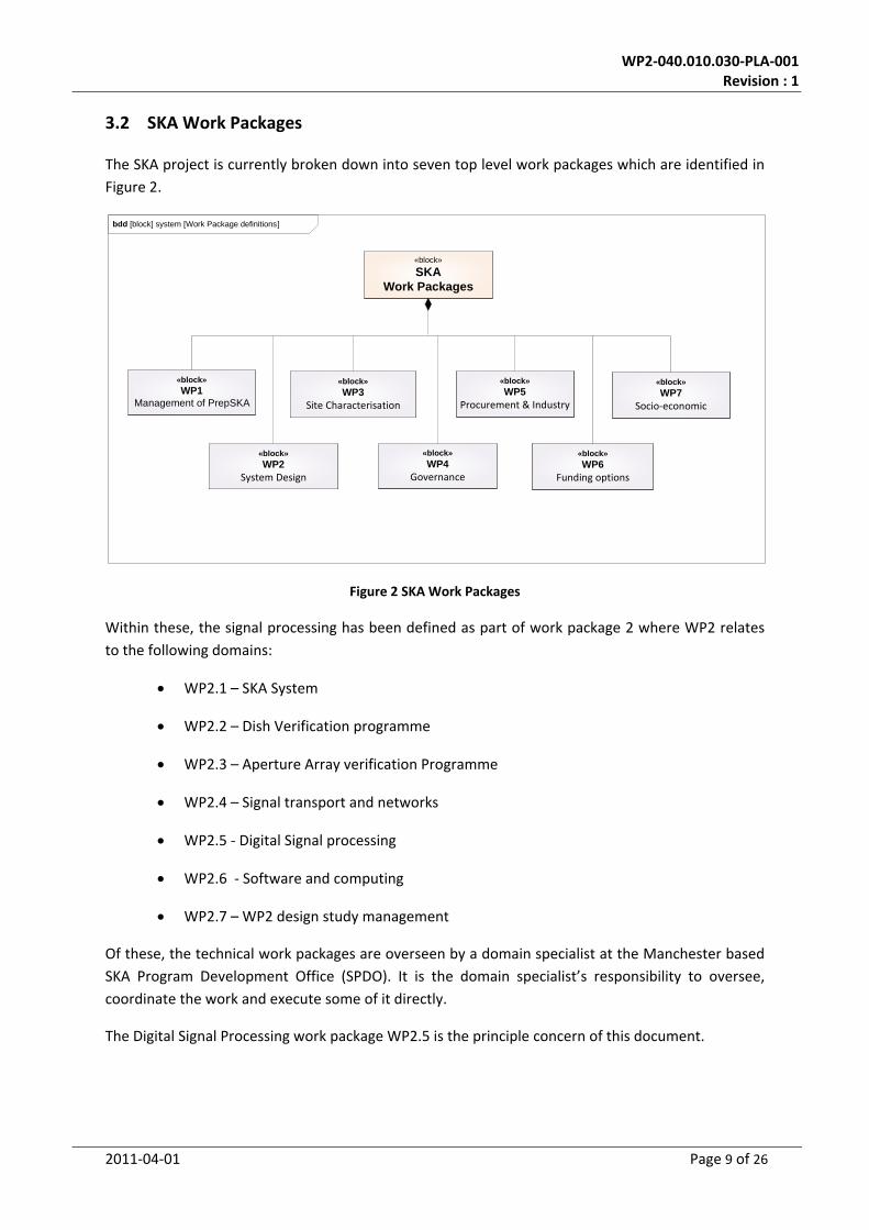
3.2 SKA Work Packages
The SKA project is currently broken down into seven top level work packages which are identified in
Figure 2.
Figure 2 SKA Work Packages
Within these, the signal processing has been defined as part of work package 2 where WP2 relates
to the following domains:
WP2.1 – SKA System
WP2.2 – Dish Verification programme
WP2.3 – Aperture Array verification Programme
WP2.4 – Signal transport and networks
WP2.5 ‐ Digital Signal processing
WP2.6 ‐ Software and computing
WP2.7 – WP2 design study management
Of these, the technical work packages are overseen by a domain specialist at the Manchester based
SKA Program Development Office (SPDO). It is the domain specialist’s responsibility to oversee,
coordinate the work and execute some of it directly.
The Digital Signal Processing work package WP2.5 is the principle concern of this document.
bdd [block] system [Work Package definitions]
«block»
SKAWork Packages
«block»
WP2System Design
«block»
WP3Site Characterisation
«block»
WP5Procurement & Industry
«block»
WP4Governance
«block»
WP6Funding options
«block»
WP7Socio‐economic
«block»
WP1Management of PrepSKA

WP2‐040.010.030‐PLA‐001 Revision : 1
2011‐04‐01 Page 10 of 26
Although the preparatory phase will not have been completed, the structure described above will be
replaced by the end of 2011 with the establishment and transition to the SKA Project Office (SPO)
(see [2] for more details)
As the project moves forward it will be important to increase the momentum, and aspects such as
the growth of the SKA organisation and approval of funding will be key milestones and stimulants to
achieve this goal. However, the large scale influences as set out in paragraph 4.2 may have
significant impact on the project as and when these influences occur.
3.3 WP2.5 Digital Signal Processing
The Digital Signal Processing (WP2.5) work packages and their hierarchy in relation to the SKA work
package 2 are detailed in Figure 3
Figure 3 Work Package 2 Taxonomy
The next level in the hierarchy for the WP2.5 Digital Signal Processing work package comprises of
three parts:
WP2.5.1 Correlator and Central Beamformer
WP2.5.2 Digital Beam‐formers
WP 2.5.3 Non‐Imaging Processing
bdd [block] system [Work Package definitions]
«block»
WP2
«block»WP2.2
Dish Verification
«block»WP2.3
Aperture Array Verification
«block»WP2.5
Digital Signal Processing
«block»WP2.4
Signal Transport & Networks
«block»WP2.6
Software & Computing
«block»WP2.7
Design Study
«block»WP2.1System
«block»
WP2.5.1Correlator & Central
Beamformer
«block»
WP2.5.2Digital Beamformers
«block»
WP2.5.3Non-Imaging Processing

WP2‐040.010.030‐PLA‐001 Revision : 1
2011‐04‐01 Page 11 of 26
The signal processing Concept Design Review (CoDR) will focus on work that has been performed
against these work‐packages with a focus on phase 1 of the SKA project whilst considering
extensibility to phase 2.
Details with regards to the WP2 objectives and work are presented in [3]. In summary the primary
objective, and therefore the focus within the SPDO signal processing domain, is to produce a
detailed costed system design for the signal processing aspects of SKA1 supported by a deployment
plan for the full SKA. It is towards this goal that all the effort is directed, with the establishment of
the conceptual baseline following the successful completion of the CoDR as the first and important
milestone on this road.
3.4 Signal Processing Time Line
Having presented the SKA top level time line in Figure 1, a more detailed diagram is presented to
provide the context of the Signal Processing domain schedule and milestones in Figure 4
Figure 4 Signal processing time scales
This figure also identifies the funding phases for PrepSKA and the Project Execution Plan. The CoDR
review for the signal processing domain is in the PrepSKA phase under the control of the SPDO whilst
the other key milestone reviews are in the PEP phase which is co‐ordinated by the successor to the
SPDO.
The milestone reviews are briefly described below.
3.4.1 Conceptual Design Review, CoDR
The purpose of the Conceptual Design Review is to review potential solutions against systems
requirements. The outcome of the review will provide recommendations on how to proceed in
terms of which presented solutions are judged to have potential and be worth
investigating/developing further, and weed‐out presented solutions that might have fundamental or
Signal Processing
2009 2010 2011 2012 2013 2014 2015 2016 2017 2018
Sub-System Definition
CoDR PDR CDR
Milestones SKA1 Final DRMSite
decision
Costed system design
2009 2010 2011 2012 2013 2014 2015 2016 2017 2018
SKA2 Signal Processors Definition and Design
SRR
Early Fabrication
PR
Factory
Site Assembly, Integration and Testing
Front End and Channeliser
Beamformer and Correlator
Pulsar and Transient Processor
SKA1 Construction, Verification, Commissioning, Acceptance, Integration & First Science
SKA Preparatory Phase
Detailed Design
Start of Phase 1 Construction
Rev 102011-03-16truncated
Concept
SRRSystem CoDRSKA1 Systems integration
PDR CDR
Phase 1 Verification and Commisioning
Detailed Design
Final SKA Deployment PlanProject management
PM Plan & Schedule
SKA Scope definitionPrepSKA
PlanProject staffing & developmentWBS, resource allocation
CoDR PDR CDR
REV REVScience DRM Development
Revision of Science Case
REV
Refinement of Early Science Shared Risk Science Operations
REVSKA2 Science Development
REV REV
Science / Engineering tradeoffs
Early Science Proposals
Continuous Performance Evaluation
Project execution, monitor and control
SKA1 construction approval
Preliminary DesignDefinitionConceptSKA1
SKA2
Continued SKA1 SE/Change management
dCoDR
Definition and high level Preliminary Design Preliminary Design
PDRDetailed Design
Demonstration and testing
AIP definition, development and fabricationAIP PAF or AA-mid Preliminary DesignPAF or AA-mid Detailed Design
AIP SKA2 DecisionAIP SKA1 Decision
PR
CoDRPhase 1 System Testing
SW Correlator Preliminary Design
Embedded Correlator Preliminary Design
Non Imaging Processor Preliminary Design
Detailed Design
Detailed Design
Factory Assembly, Integration and Testing
Site Assembly, Integration and Testing
SKA1 Pre-construction Phase
PrepSKA PEP
WP2‐040.010.030‐PLA‐001 Revision : 1
2011‐04‐01 Page 12 of 26
technical problems, or require further investigation. In addition, if potential solutions are not
presented for particular problems, to point out/ highlight those as requiring further detailed
investigation/study.
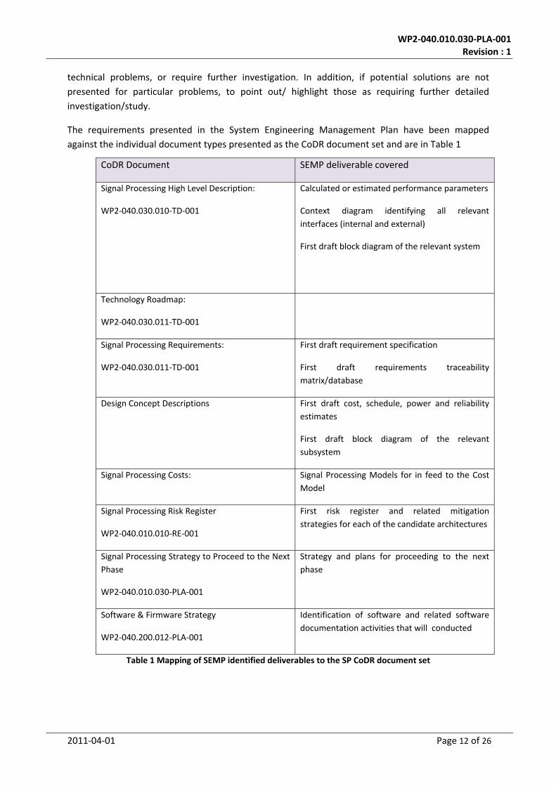
The requirements presented in the System Engineering Management Plan have been mapped
against the individual document types presented as the CoDR document set and are in Table 1
CoDR Document SEMP deliverable covered
Signal Processing High Level Description:
WP2‐040.030.010‐TD‐001
Calculated or estimated performance parameters
Context diagram identifying all relevant
interfaces (internal and external)
First draft block diagram of the relevant system
Technology Roadmap:
WP2‐040.030.011‐TD‐001
Signal Processing Requirements:
WP2‐040.030.011‐TD‐001
First draft requirement specification
First draft requirements traceability
matrix/database
Design Concept Descriptions First draft cost, schedule, power and reliability
estimates
First draft block diagram of the relevant
subsystem
Signal Processing Costs: Signal Processing Models for in feed to the Cost
Model
Signal Processing Risk Register
WP2‐040.010.010‐RE‐001
First risk register and related mitigation
strategies for each of the candidate architectures
Signal Processing Strategy to Proceed to the Next
Phase
WP2‐040.010.030‐PLA‐001
Strategy and plans for proceeding to the next
phase
Software & Firmware Strategy
WP2‐040.200.012‐PLA‐001
Identification of software and related software
documentation activities that will conducted
Table 1 Mapping of SEMP identified deliverables to the SP CoDR document set

WP2‐040.010.030‐PLA‐001 Revision : 1
2011‐04‐01 Page 13 of 26
3.4.2 System Requirements Review, SRR
The SRR, conducted at the end of the definition phase, will review primarily the definition of the
specific building item as reflected in its relevant Requirement Specification. The review will typically
be conducted after the conclusion of the requirement analysis and validation activities.
As detailed in the System Engineering Management Plan WP2‐005.010.030‐MP‐001 [4], delivered
SRR outputs to be reviewed at this stage will include:
•Report outlining the findings of the investigations of the candidate technology options and
statements and justifications of the selected baseline option to be carried forward
•Finalised requirement specification (including the cross verification matrix indicating the
kind of tests to be performed for each of the requirements).
•First draft interface control documents (internal and external)
•First draft of the architectural design description document
•First draft acceptance test plan/procedure
•Updated risk register and related mitigation strategies
•Updated block diagram of the relevant system, element or subsystem
•Updated requirements traceability matrix/database
•Strategy and plans for proceeding to the next phase
•Updated Cost, schedule, power and reliability estimates
•Logistical and software documents (To be defined)
•First draft health and safety plan
The output of this review is a well defined item at the project level at which it is being performed.
3.4.3 Preliminary Design Review, PDR
The PDR will be conducted at the end of the preliminary design phase and is aimed to review and
confirm the final design of the item as reflected in its relevant Architectural Design Description
Document. The review will be performed at the conclusion of the functional analysis, verification,
synthesis and design verification activities at the end of the preliminary design phase.
As detailed in the System Engineering Management Plan [4] (which takes precedence), delivered
PDR outputs to be reviewed at this stage will include:
•Revised and final requirements specification
•Final architectural design description document
•Final interface control documents (internal and external)

WP2‐040.010.030‐PLA‐001 Revision : 1
2011‐04‐01 Page 14 of 26
•Final block diagram
•Acceptance test plans and procedures
•First draft integration plan
•Updated requirements traceability matrix/database
•Consumables, spares and test equipment
•Updated risk register and relating mitigations strategies
•Upgrade plans
•Roll out/build plans
•Logistical and software documents (To be defined)
•Audit of manufacturing data packs for designs to be carried forward
•Final health and safety plan
Together, the above set of documents must reflect the fully costed design of the item. The output of
the review will be a fully designed item at the project level at which it is being performed at.
3.4.4 Critical Design Review, CDR
The CDR will be performed at the end of the detailed design phase and will determine whether the
item under review is ready to enter the preliminary production phase.
As detailed in the System Engineering Management Plan [4], delivered CDR outputs to be reviewed
at this stage will include:
•Confirmation of the requirement specification and design description baseline
•Review of all aspects of the production process as well as the supporting documents
(manufacturing data packs).
•Review of test and verification plans/procedures
•Review of updated risk registers
•Presentation of final design data on costs, power, reliability etc.
•Review of integration and test plans
The exact details of this phase will be developed and expanded during PrepSKA.

WP2‐040.010.030‐PLA‐001 Revision : 1
2011‐04‐01 Page 15 of 26
4 Gaps in the Concept Phase
Table 1 identified the deliverables, defined in the SEMP, to be covered at the CoDR. On the whole,
these have been provided with reasonable coverage. However, there are some gaps that have been
identified that are not necessarily easily addressed in the time scales of the CoDR.
The short falls are:
Remote Station (Dish) Beamforming concept (SKA2)
Reliability estimates
Software development and costing strategy
4.1.1 Remote Station Beamforming Concept
There has been no concept put forward at the CoDR for beam‐forming of the remote stations for
dishes that are primarily part of phase 2 of the project. There are two key reasons for this:
The perception is that remote station beam‐forming is trivial
The system requirements for the dish stations are not defined
To ascertain whether the beamforming is trivial and the gap isn’t large a quick calculation is
performed to determine a ball park processing power and communication bandwidth. To do this
some assumptions are made:
Dish station diameter is of the order of 250 metres
There are ~ 20 dishes per dish station
The instantaneous bandwidth is 3.5 GHz
There are ~ 40 Dish Stations
Number of beams is less than 5
The beam‐forming load is consequently:
5 25 3.5 2 1 875
The input bandwidth is:
25 3.5 2 4 700 /
Reading across from the Sparse AA Beamformer concept, this could be implemented in one
Uniboard (or equivalent) for a board cost of €10k and a thermal dissipation of under 350 Watts per
station.
Consequently, the gap isn’t regarded as significant but should be addressed within the next phase

WP2‐040.010.030‐PLA‐001 Revision : 1
2011‐04‐01 Page 16 of 26
During the Definition phase the Signal Processing domain will iterate with the system level to
establish the requirements associated with dish station beamforming.
4.1.2 Reliability and Maintainability, RAM, Estimates
A requirement identified for inclusion at the CoDR is first draft estimates of Reliability for each of the
presented concepts. Table 2 provides a summary of each of the concepts and whether RAM was
considered.
Concept Reliability Figures Available Y/N
Software Correlator N
Giant Systolic Array Y
ASKAP Style Correlator N
UNIBOARD Correlator N
CASPER Correlator N
Low Power Correlator N
SKADS AA Correlator N
Central Beamformer N
Station Beamformer N
Non‐Imaging Processing N
PAF Beamforming N
FPGA Pulsar Processing N
Table 2 Reliability Coverage in Concept Descriptions
As can be seen from this table RAM has, for the most part, not been considered so far. To close this
gap in the Definition phase, the Signal Processing domain needs to work closely with the System
domain to define the requirements and the methodology for calculating RAM.
Typically Telcordia SR‐332 (telecom standard) and MIL HDBK 217F are used to provide reliability
estimates. Manufactures also provide measured reliability data. For example, Xilinx published a
reliability report in Q3 2010:
http://wiki.skatelescope.org/pub/SignalProcessing/WebHome/ug116.pdf
From this report the reliability of the FPGAs is typically 50 to 200 FITS (failures in 109 hours) which is
in line with the reliability estimates for an ASIC [5]. It is assumed GPU processing chips are of a
similar complexity and will have a reliability of the order of 50 to 500 FITs.
The use of reliability figures in conjunction with reliability block diagrams are now to be addressed in
the Definition phase.

WP2‐040.010.030‐PLA‐001 Revision : 1
2011‐04‐01 Page 17 of 26
Infant mortality is also addressed in the GSA correlator document [5]. Infant mortality includes
issues relating to silicon failures, defective solder joints, cabling failures/installation errors,
connector contact failures etc.
The EVLA, found a correlation between complexity/number of solder joints, and infant failures.
Plans to include eng‐model and production‐model reliability testing (if any), for example HALT/HAST
need to be considered across all concepts.
Reliability estimates for human factors need to be consider which reliability tools like Relex
reliability software can estimate.
Soft‐FPGA failures due to configuration SRAM upsets can be an issue and need to be considered as
part of RAM. The EVLA has ~15k FPGAs and are seeing on the order of 1‐3 events per month which
need human intervention to fix. With a much more complex system, and presumably many more
FPGAs, a methodology for deal with this issue needs to be identified possibly including some form of
automatic recovery. ALMA, have a plan was to reboot all FPGAs ~once per day to deal with the issue
whether this is effective needs to be ascertained in the definition phase.
Software reliability is to be included in RAM.
4.1.3 Software development and costing strategy
Software development and costing strategy for signal processing is to be aligned with that of the
software and computing domain and utilised the procedures developed as part of the domain.
5 Definition Phase
The Definition phase immediately follows the Concept phase and associated CoDR and leads to the
requirements review, SRR, as detailed in Figure 5
Figure 5 Phases, reviews and baselines
The following sections provide an overview of the strategy to proceed from the CoDR towards the
SRR. This includes:
WP2‐040.010.030‐PLA‐001 Revision : 1
2011‐04‐01 Page 18 of 26
A definition of the tools required to support the definition phase
The documentation that is to be developed for the SRR
Tasks required for the development of the concepts presented at the CoDR
Resources available
The activities in the definition phase will continue to work with a top down and bottom up approach
with activities supporting the Element Level Signal Processing activities such as the Element level
requirements whilst continuing the development of the individual concepts.
5.1 Tools
During the Definition phase the complexity of the system, the number of requirements and quantity
of documentation is expected to increase significantly across all domains. As an aid to dealing with
this complexity and ensuring consistency and tractability across the system, tools for requirement,
document and modelling are being considered.
5.1.1 Requirements
It will be mandatory for the SKA Requirements Engineering activity to employ tools to ensure
traceability, completeness, change control and adequate verification. The SPDO does not have the
resources to yet fully implement tools, but the process of identification and selection has started on
the basis of evaluation licensing, principally in relation to IBM offerings.
5.1.2 Document Management
Document Management, including Change Control, is being evaluated making use of the CERN EDMS
system. The deployment of EDMS, or an alternative Data Management System, may necessitate a
retrospective change to the document numbering scheme.
5.1.3 Modelling
Work on the identification and evaluation of Model Based System Engineering tools is expected to
accelerate once resources are available and the Requirements Capture phase ramps down. The
most pressing application of Modelling is in cost/performance trade‐off studies, and the existing
models will be integrated once the tools have been deployed.
WP2‐040.010.030‐PLA‐001 Revision : 1
2011‐04‐01 Page 19 of 26
5.2 SRR Document Tree
Figure 6 SRR Document Tree
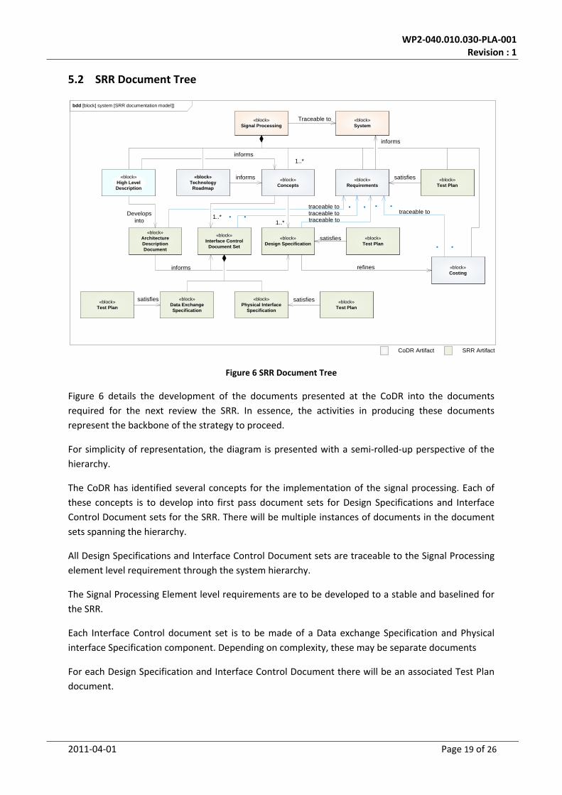
Figure 6 details the development of the documents presented at the CoDR into the documents
required for the next review the SRR. In essence, the activities in producing these documents
represent the backbone of the strategy to proceed.
For simplicity of representation, the diagram is presented with a semi‐rolled‐up perspective of the
hierarchy.
The CoDR has identified several concepts for the implementation of the signal processing. Each of
these concepts is to develop into first pass document sets for Design Specifications and Interface
Control Document sets for the SRR. There will be multiple instances of documents in the document
sets spanning the hierarchy.
All Design Specifications and Interface Control Document sets are traceable to the Signal Processing
element level requirement through the system hierarchy.
The Signal Processing Element level requirements are to be developed to a stable and baselined for
the SRR.
Each Interface Control document set is to be made of a Data exchange Specification and Physical
interface Specification component. Depending on complexity, these may be separate documents
For each Design Specification and Interface Control Document there will be an associated Test Plan
document.
bdd [block] system [SRR documentation model]]
«block»Signal Processing
«block»Interface Control
Document Set
«block»Data Exchange Specification
«block»Physical Interface
Specification
«block»Design Specification
«block»Architecture DescriptionDocument
«block»Requirements
«block»Test Plan
«block»Test Plan
«block»Technology Roadmap
«block»Test Plan
informs
satisfies
«block»Concepts
satisfies
1..*
Develops into
satisfies
«block»Test Plan
traceable to
1..*1..*
satisfies
informs
«block»System
Traceable to
«block»High Level Description
informs
«block»Costing
refines
traceable to traceable to
informs
traceable to
CoDR Artifact SRR Artifact

WP2‐040.010.030‐PLA‐001 Revision : 1
2011‐04‐01 Page 20 of 26
The High Level Description will develop into an Architecture Description Document which is to be
traceable to the Signal Processing Element level requirements and is to inform the Design and
Interface Control Document set specifications
The costing document is to be refined to include in feed from the Design Specifications. This is to
include expanding the coverage for the template identified in the costing how to document
Section 3.4.2 details the deliverables identified in the SEMP for the SRR.
5.3 Signal Processing Requirements
As illustrated in Figure 6, the Signal Processing Element requirements form a major hub for the other
documents to be presented at the SRR. Consequently, a large amount of effort between the CoDR
and the SRR is to be allocated to developing this document such that there is complete coverage and
traceability of the requirements.
The associated Test Plan is to be generated as in feed to the SRR but is only required to be a first
pass
5.4 Further Development of Concepts
A two pronged approach to the development of each concept to be carried forward from the CoDR.
This is to include:
Generation of documentation supporting the SRR
Evaluation of technology
The SRR documentation is dealt with in section 5.2. The following sections identify the types of
activities expected for the technology evaluation for each type of concept.
5.4.1 Software Correlator
Address gaps identified at the CoDR (if any)
Development of a Software Correlator Architecture Description Document including sub‐system requirements
Development of a Software Correlator design specification set including sub‐system requirements
Development of a Software Correlator Interface Control Document set including interface requirements in the form of a Data exchange Specification and Physical interface specification sets
Identify, optimal communications topology in terms of cost and performance between processing nodes including latency and jitter characterization. This will potentially include optimisations of the OS communications stack including memory buffer sizing to avoid data loss.
Identify scalability of software correlator solution in terms of cost and thermal dissipation as a function of number of antenna and correlation algorithms
Identify a Monitoring and Control philosophy that is inclusive of any hardware acceleration cards. Built in test and Power on Self Test should be considered. For a software correlator and supporting network, SNMP and RMON might be considered for hardware and OS

WP2‐040.010.030‐PLA‐001 Revision : 1
2011‐04‐01 Page 21 of 26
monitoring. However, monitoring needs to cover the functionality of the correlator Application too.
Identify a system boot mechanism that provides a reasonable boot time (say 3 to 4 minutes for the application to be running from cold start)
Identify an automated mechanism for software update (possibly along the lines of Linux’s Anaconda?)
Specify software test harnesses to ‘stress test’ the software correlator in terms of simultaneous processing and communications load. This could also be used to make power and temperature measurements as a function of load.
Characterise the performance of compilers possibly including a comparison of manufacturer’s against open source GNU.
Identify all licensing issues with respect to software, OS and support tools.
Identify any environmental limitations of the equipment: operating and storage temperatures, humidity, shock vibration etc.
Identify any Health and Safety issues for the equipment.
Determine the support period and warranty offered on products.
Estimate Non Recurring Costs including software development. It is expected that function point analysis or equivalent will be used for costing.
Estimated reliability figures
5.4.2 Embedded Correlator
This section refers to concepts based on FPGA and ASIC technology
Address gaps identified at the CoDR (if any)
Development of a Embedded Correlator Architecture Description Document including sub‐system requirements
Development of a Embedded Correlator design specification set including sub‐system requirements
Development of a Embedded Correlator Interface Control Document set including interface requirements in the form of a Data exchange Specification and Physical interface specification sets
Identify and evaluate candidate architectures. Currently, the FX architecture is favoured. However, the scale of the SKA in terms of number of antenna, baseline length and fields of view create new challenges. These include:
o FFT lengths required in the Channelizer.
o F to X corner turner
o Memory requirements for correlation results
o Data rate to Science Computing
Determine the number of bits required at different stages of the processing chain and model bit truncation.
Model channelizer implementation to determine the associated processing and memory requirements and performance in terms of cross talk between channels. Consideration is to be given to coarse/fine channel split with up‐sampling.
Identify optimal communications topology in terms of cost, performance and thermal dissipation between channelizer and correlator.
Identify all licensing issues with respect to software, OS and support tools.

WP2‐040.010.030‐PLA‐001 Revision : 1
2011‐04‐01 Page 22 of 26
Identify any Health and Safety issues for the equipment.
Determine the support period and warranty offered on products.
Where bespoke designs are being implemented, ascertain through modelling (possibly using CAD software) the key physical constraints of the design. This might include the number of processing devices per card/ module.
Propose Equipment Practice detailing cabinets, racking, cooling and cabling.
Determine the topology and technology options for communication between correlator processing nodes
Estimate Non Recurring Costs including software development. It is expected that function point analysis or equivalent will be used for costing.
Estimated reliability figures
5.4.3 Tasks related specifically to Central Beamformer Design
Address gaps identified at the CoDR (if any)
Development of a Central Beamforming Architecture Description Document including sub‐system requirements
Development of a Central Beamformer design specification set including sub‐system requirements
Development of a Central Beamformer Interface Control Document set including interface requirements in the form of a Data exchange Specification and Physical interface specification sets
Identify calibration requirements and any differences in configurations required for different experiments trading bandwidth, precision, FoV etc.
Model/ simulate beam‐former.
Determine the number of bits required at different stages of the processing chain and model any bit truncation.
Ascertain beam‐former coefficient update rate and determine the associated processing load and bandwidth implications in delivering coefficients to beam‐former.
Identify and model RFI Mitigation algorithms suitable for implementation within beam‐forming hardware
Identify optimal communications topology in terms of cost, performance and thermal dissipation.
Liaise with AA_low and Dish Receptor design teams to derive the number of frequency channels required to support beam‐forming and ascertain the merits and pit falls of including channelization
Identify all licensing issues with respect to software, OS and support tools.
Identify any Health and Safety issues for the equipment.
Determine the support period and warranty offered on products.
Where bespoke designs are being implemented, ascertain through modelling (possibly using CAD software) the key physical constraints of the design. This might include the number of processing devices per card/ module.
Propose Equipment Practice including card, shelf and cabinet standards and associated PSUs and cooling
Determine the topology and technology options for communication between beam‐former processing nodes
Estimate Non Recurring Costs including software development. It is expected that function point analysis or equivalent will be used for costing.
Estimated reliability figures

WP2‐040.010.030‐PLA‐001 Revision : 1
2011‐04‐01 Page 23 of 26
5.4.4 Tasks related specifically to Non Imaging processing
Address gaps identified at the CoDR (if any)
Development of a Non‐Imaging Architecture Description Document including sub‐system requirements
Development of a Non‐Imaging design specification set including sub‐system requirements
Development of a Non‐Imaging Interface Control Document set including interface requirements in the form of a Data exchange Specification and Physical interface specification sets
Work with the System team to ensure sufficient coverage of requirements to allow progress in developing and sizing implementation concepts. This particularly relates to the parameter space associated with Binary Pulsar systems
Work with the System requirement team to develop use cases for the Non‐Imaging processing.
Develop optimal Coherent De‐dispersion implementation
Analyse and evaluate Binary search algorithms against search parameter space
Analyse and evaluate automated detection algorithms
Determine the number of bits required at different stages of the processing or data storage chain and model any bit truncation.
Identify, optimal communications topology in terms of cost and performance between processing nodes including latency and jitter characterization. This will potentially include optimisations of the OS communications stack including memory buffer sizing to avoid data loss.
Identify a Monitoring and Control philosophy that is inclusive of any hardware acceleration cards. Built in test and Power on Self Test should be considered. SNMP and RMON might be considered for hardware and OS monitoring. However, monitoring needs to cover the functionality of the Non‐Imaging applications too.
Identify a system boot mechanism that provides a reasonable boot time (say 3 to 4 minutes for the application to be running from cold start)
Identify an automated mechanism for software update (possibly along the lines of Linux’s Anaconda?)
Specify software test harnesses to ‘stress test’ the Non‐Imaging processing in terms of simultaneous processing and communications load. This could also be used to make power and temperature measurements as a function of load.
Characterise the performance of compilers possibly including a comparison of manufacturer’s against open source GNU.
Identify power requirements including but not limited to wattage, required voltages, any special power sequencing needs and UPS needs to allow orderly shutdown of equipment
Identify all licensing issues with respect to software, OS and support tools.
Identify any environmental limitations of the equipment: operating and storage temperatures, humidity, shock vibration etc.
Identify any Health and Safety issues for the equipment.
Determine the support period and warranty offered on products.
WP2‐040.010.030‐PLA‐001 Revision : 1
2011‐04‐01 Page 24 of 26
5.5 List of Resources
Table 4 Includes the official [ref] list of the people and institutions that have volunteered to provide effort for the PrepSKA phase of the SKA against
particular work packages. These have been organised such that the Lead Institution co‐ordinates the work in the work package from the Participating
organisations.
Work
Package
SPDO
Domain
Specialist
WP
number
Task Lead Institutes Task Leader Participating Institutes Resources
WP2.5
Digital Signal
Processing
W. Turner
2.5.1 Correlator and central beamformer DRAO B.Carlson JIVE A. Szomoru
KASI J. Kim
NCRA Y. Gupta
CSIRO J. Bunton
NRF F. Kapp
2.5.2 Digital Beamformers
2.5.2.1 PAFs CSIRO J Bunton ASTRON W. van Cappellen
DRAO B. Veidt
UCAL L. Bruton

WP2‐040.010.030‐PLA‐001 Revision : 1
2011‐04‐01 Page 25 of 26
2.5.2..2 AAs AAVP
2.5.2.3 Station Beamforming UK M.Jones
C.Shenton
MPIfR R. Keller
ASTRON A.Gunst
DRAO B.Carlson
INAF S. Montebugnoli
2.5.3 Non‐Imaging UK B.Stappers ASTRON J.G. Bij de Vaate
CSIRO J.Bunton
MPIfR R. Keller
NRF F. Kapp
OBSPAR C. Viou
UORL R. Weber
2.5.4 Software Correlators KASI J. Kim
NCRA Y. Gupta
UK P.Alexander
Table 3 List of Resources1
In addition to this list, other institutions are providing support including: ICRAR: T. Colgate and N. Clarke for Non Imaging processing including transients and dedispersion
1 Taken from [3]

WP2‐040.010.030‐PLA‐001 Revision : 1
2011‐04‐01 Page 26 of 26
JPL: L. Daddario, R.Navarro, K. Wagstaff, W.Majid for Correaltion and Non Imaging processing including dedispersion and auto detection
5.6 Estimated Contributions to Remainder of WP2
WP Description SPDO ASTRON CSIRO DRAO ICRAR INAF MPIfR NCRA‐
TIFR
OBSPAR TDP UK Other Totals
2.5 Digital Signal Processing 14 7 40 15 83.5 160.5
Table 4 Estimated person month contributions from 1 January 2011 to 31 March 20122
2 In process of being finalised [3]


![Very Long Baseline Interferometry with the SKA · 2014. 12. 19. · VLBI with the SKA Zsolt Paragi SKA Band SKA-core Bandwidth Remote tel. Baseline sens. Image noise SEFD [Jy] [MHz]](https://static.fdocuments.us/doc/165x107/60afd58c2cb342480e46c8a7/very-long-baseline-interferometry-with-the-ska-2014-12-19-vlbi-with-the-ska.jpg)