SK255KD RoHS - TME
5
Revised: 08/20/15 Specifications are subject to change without notice. ©2015 Littelfuse, Inc Teccor ® brand Thyristors 55 Amp Standard SCRs SK255KD SK255KD Main Features Symbol Value Unit I T(RMS) 55 A V DRM /V RRM 1200 V I GT 50 mA Absolute Maximum Ratings Symbol Parameter Test Conditions Value Unit V DRM /V RRM Repetitive Peak off-state/Reverse Voltage 1200 V V DSM /V RSM Non-repetitive peak off-state/Reverse voltage 1300 V I T(RMS) RMS on-state current T C = 60°C 55 A I T(AV) Average on-state current T C = 60°C 35 A I TSM Peak non-repetitive surge current single half cycle; f = 50Hz; T J (initial) = 25°C 520 A single half cycle; f = 60Hz; T J (initial) = 25°C 620 I 2 t I 2 t Value for fusing t p = 8.3 ms 1620 A 2 s di/dt Critical rate of rise of on-state current 150 A/μs I GM Peak gate current T J = 125°C 3 A P G(AV) Average gate power dissipation T J = 125°C 1 W T stg Storage temperature range -40 to 150 °C T J Operating junction temperature range -40 to 125 °C Description Excellent unidirectional switches for phase control applications such as heating and motor speed controls. Standard phase control SCRs are triggered with few milliamperes of current at less than 1.5V potential. Features & Benefits • RoHS compliant • Voltage capability up to 1200 V • Surge capability up to 550 A • Electrically isolated package “KD-Package” and UL recognized for 2500V RMS Schematic Symbol Applications Typical applications are AC solid-state switches, industrial power tools, line rectification 50/60Hz. A K G Agency Approval Agency Agency File Number E71639 RoHS
Transcript of SK255KD RoHS - TME
Revised: 08/20/15
Specifications are subject to change without notice. ©2015 Littelfuse, Inc
Teccor® brand Thyristors 55 Amp Standard SCRs
SK255KD
SK255KD
Main Features
Symbol Value Unit
IT(RMS) 55 A
VDRM/VRRM 1200 V
IGT 50 mA
Absolute Maximum Ratings
Symbol Parameter Test Conditions Value Unit
VDRM /VRRM Repetitive Peak off-state/Reverse Voltage 1200 V
VDSM/VRSM Non-repetitive peak off-state/Reverse voltage 1300 V
IT(RMS) RMS on-state current TC = 60°C 55 A
IT(AV) Average on-state current TC = 60°C 35 A
ITSM Peak non-repetitive surge current
single half cycle; f = 50Hz; TJ (initial) = 25°C
520
Asingle half cycle; f = 60Hz;
TJ (initial) = 25°C620
I2t I2t Value for fusing tp = 8.3 ms 1620 A2s
di/dt Critical rate of rise of on-state current 150 A/μs
IGM Peak gate current TJ = 125°C 3 A
PG(AV) Average gate power dissipation TJ = 125°C 1 W
TstgStorage temperature range -40 to 150 °C
TJ Operating junction temperature range -40 to 125 °C
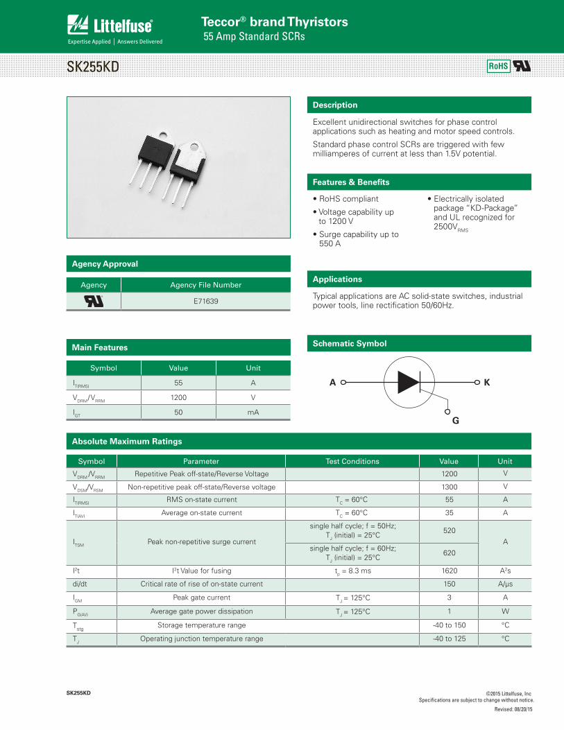
Description
Excellent unidirectional switches for phase control applications such as heating and motor speed controls.
Standard phase control SCRs are triggered with few milliamperes of current at less than 1.5V potential.
Features & Benefits
• RoHS compliant
• Voltage capability up to 1200 V
• Surge capability up to 550 A
• Electrically isolated package “KD -Package” and UL recognized for 2500VRMS
Schematic Symbol
Applications
Typical applications are AC solid-state switches, industrial power tools, line rectification 50/60Hz.
A K
G
Agency Approval
Agency Agency File Number
E71639
RoHS
Revised: 08/20/15
Specifications are subject to change without notice. ©2015 Littelfuse, Inc
Teccor® brand Thyristors 55 Amp Standard SCRs
SK255KD
Electrical Characteristics (TJ = 25°C, unless otherwise specified)
Symbol Test Conditions Value Unit
IGTVD = 12V; RL = 30 Ω
MAX. 50 mA
VGT MAX. 1.5 V
dv/dt VD = 2/3 VDRM; gate open; TJ = 125°C MIN. 2000 V/μs
VGD VD = VDRM; RL = 3.3 kΩ; TJ = 125°C MIN. 0.2 V
IH IT = 500mA (initial) MAX. 120 mA
tq IT=0.5A; tp=50µs; dv/dt=5V/µs; di/dt=-30A/µs TYP. 20 μs
tgt IG = 2 x IGT; PW = 15µs; IT = 110A TYP. 3 μs
Thermal Resistances
Symbol Parameter Value Unit
Rθ(J-C)Junction to case (AC) 1.0 °C/W
Static Characteristics
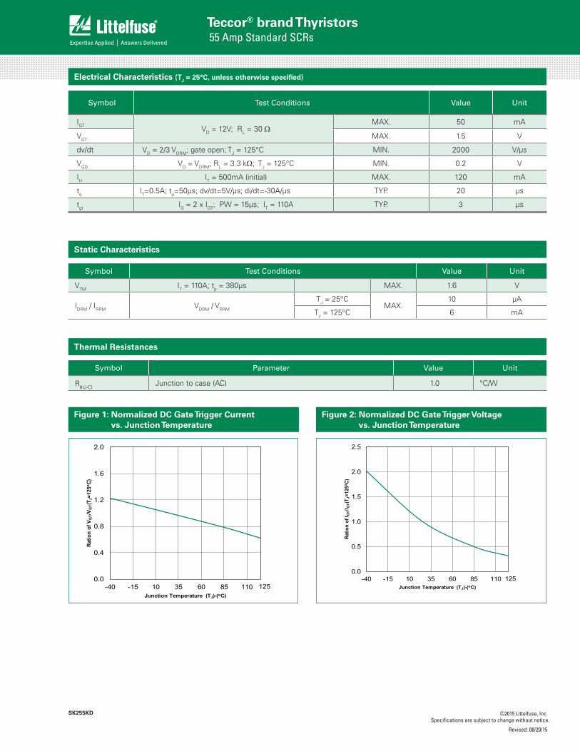
Figure 1: Normalized DC Gate Trigger Current vs. Junction Temperature
Figure 2: Normalized DC Gate Trigger Voltage vs. Junction Temperature
0.0
0.4
0.8
1.2
1.6
2.0
-40 -15 10 35 60 85 110
Ratio
n of
VG
T/V G
T(T J
=125
o C)
Junction Temperature (TJ)-(oC)125
0.0
0.5
1.0
1.5
2.0
2.5
-40 -15 10 35 60 85 110
Ratio
n of
I GT/
I GT(
T J=1
25o C
)
Junction Temperature (TJ)-(oC)125
Symbol Test Conditions Value Unit
VTM IT = 110A; tp = 380μs MAX. 1.6 V
IDRM / IRRM VDRM / VRRM
TJ = 25°CMAX.
10 μA
TJ = 125°C 6 mA

Revised: 08/20/15
Specifications are subject to change without notice. ©2015 Littelfuse, Inc
Teccor® brand Thyristors 55 Amp Standard SCRs
SK255KD
Figure 5: Power Dissipation (Typical) vs. RMS On-State Current
Figure 6: Maximum Allowable Case Temperature vs. RMS On-State Current
Figure 3: Normalized DC Holding Current vs. Junction Temperature
Figure 4: On-State Current vs. On-State Voltage (Typical)
0.0
0.4
0.8
1.2
1.6
2.0
-40 -15 10 35 60 85 110
Ratio
n of
I H/I H
(TJ=
125o C
)
Junction Temperature (TJ)-(oC)125
Instantaneous On-state Voltage (vT) – Volts
Inta
ntan
eous
On-
stat
e Cu
rren
t (iT
) – A
mps
0
20
40
60
80
100
120
140
160
0.7 0.8 0.9 1.0 1.1 1.2 1.3 1.4 1.5 1.6 1.7 1.8 1.9
0
10
20
30
40
50
60
0 5 10 15 20 25 30 35 40 45 50 55RMS On-State Current [IT(RMS)] - (Amps)
Aver
age
On-S
tate
Pow
er D
issi
patio
n[ P
D(A
V)]
- (W
atts
)
Max
imum
Allo
wab
le C
ase T
empe
ratu
re (T
C) - °C
RMS On-State Current [IT(RMS)] - Amps
40
50
60
70
80
90
100
110
120
130
0 10 20 30 40 50 60
CURRENT WAVEFORM: SinusoidalLOAD: Resistive or InductiveCONDUCTION ANGLE: 180°
Figure 7: Maximum Allowable Case Temperature vs. Average On-State Current
Average On-State Current [IT(AVE)] - Amps
Max
imum
Allo
wab
le C
ase
Tem
pera
ture
(TC) -
°C
40
50
60
70
80
90
100
110
120
130
0 5 10 15 20 25 30 35 40
CURRENT WAVEFORM: SinusoidalLOAD: Resistive or InductiveCONDUCTION ANGLE: 180°
Revised: 08/20/15
Specifications are subject to change without notice. ©2015 Littelfuse, Inc
Teccor® brand Thyristors 55 Amp Standard SCRs
SK255KD
Environmental Specifications
Test Specifications and Conditions
AC BlockingJESD22-A108C, 80% VDRM @125°C for 168 hours
Temperature CyclingJESD22-A104D, M-1051,50 cycles; -50°C to +150°C; 15-min dwell-time
Temperature/Humidity
EIA / JEDEC, JESD22-A101168 hours; 100V - DC: 85°C; 85% rel humidity
Resistance to Solder Heat
JESD22-B106C
Solderability ANSI/J-STD-002, category 3, Test A
Design Considerations
Careful selection of the correct device for the application’s operating parameters and environment will go a long way toward extending the operating life of the Thyristor. Good design practice should limit the maximum continuous current through the main terminals to 75% of the device rating. Other ways to ensure long life for a power discrete semiconductor are proper heat sinking and selection of voltage ratings for worst case conditions. Overheating, overvoltage (including dv/dt), and surge currents are the main killers of semiconductors. Correct mounting, soldering, and forming of the leads also help protect against component damage.
Dimensions – TO-218AC (KD Package) — Isolated Mounting Tab Common with Center Lead
2-R0.5
H
P E
ΦMax 4
.2mm
K
L
B
A
D
FG
J
R
C
DimensionMillimeters Inches
Min. Typ. Max. Min. Typ. Max.
A 4.40 4.60 0.173 0.181
B 1.45 1.55 0.057 0.061
C 14.35 15.60 0.565 0.614
D 0.50 0.70 0.020 0.028
E 2.70 2.90 0.106 0.114
F 15.80 16.50 0.622 0.650
G 20.40 21.10 0.803 0.831
H 15.10 15.50 0.594 0.610
J 5.40 5.65 0.213 0.222
K 1.10 1.40 0.043 0.055
L 1.35 1.50 0.053 0.059
P 2.80 3.00 0.110 0.118
R 4.35 0.171
Peak
Su
rge
(No
n-r
epet
itiv
e)O
n-s
tate
Cu
rren
t (I
TS
M)
– A
mp
s
Surge Current Duration - Full Cycles
One cycletp=10ms
1 10 100 10000
80
160
240
320
400
480
560
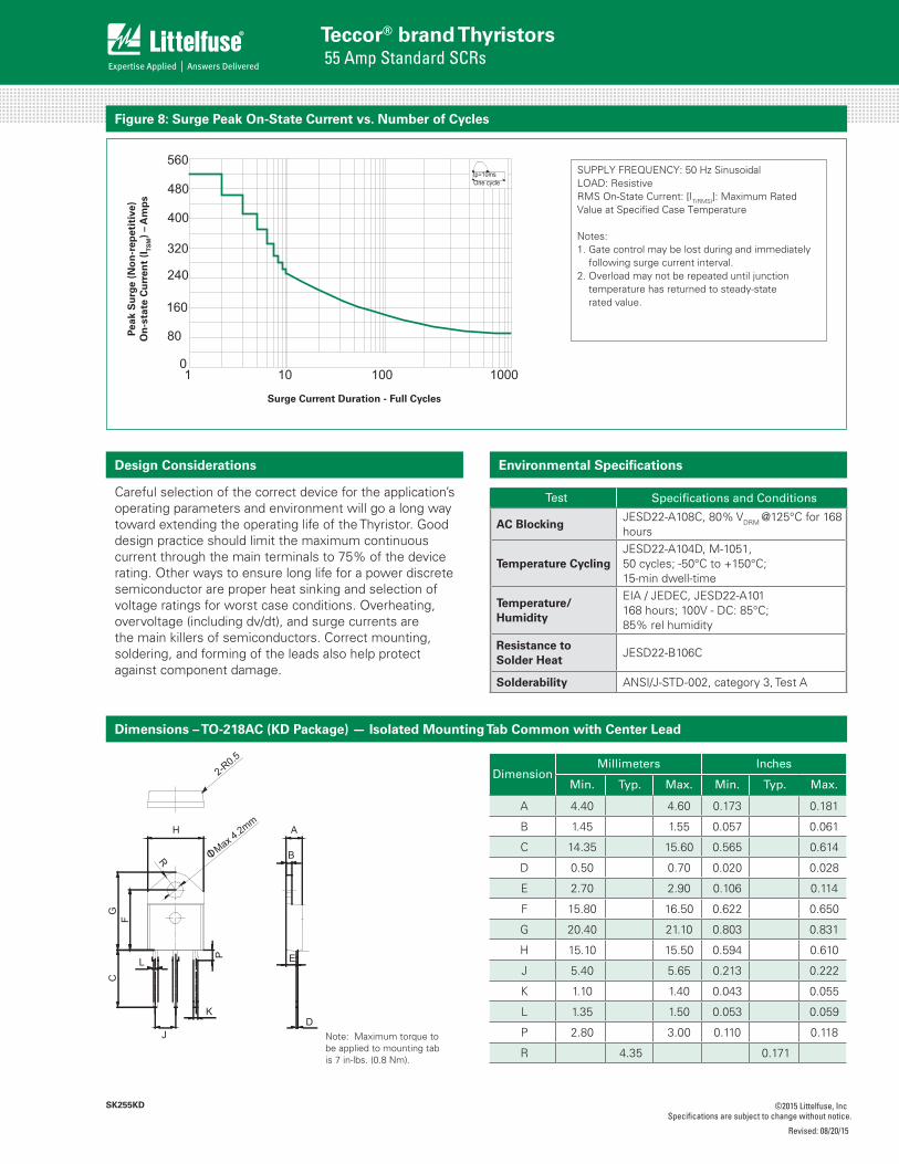
Figure 8: Surge Peak On-State Current vs. Number of Cycles
SUPPLY FREQUENCY: 50 Hz Sinusoidal LOAD: ResistiveRMS On-State Current: [IT(RMS)]: Maximum Rated Value at Specified Case Temperature
Notes:1. Gate control may be lost during and immediately
following surge current interval.2. Overload may not be repeated until junction
temperature has returned to steady-state rated value.
Note: Maximum torque tobe applied to mounting tabis 7 in-lbs. (0.8 Nm).

Revised: 08/20/15
Specifications are subject to change without notice. ©2015 Littelfuse, Inc
Teccor® brand Thyristors 55 Amp Standard SCRs
SK255KD
Product Selector
Packing Options
Part Numbering System Part Marking System
®
YMMXXX
SK255KD
Date Code MarkingY:Year CodeMM: Month CodeXXX: Lot Serial Code
S K2 55 TP
DEVICE TYPES: SCR
VOLTAGE RATINGK2: 1200VK6: 1600V
CURRENT RATING55: 55A
PACKAGE TYPE
PACKAGING TYPETP: Tube Pack
KD
KD: TO-218AC (isolated)
Part Number Gate Sensitivity Type Package
SK255KD 50mA Standard SCR TO-218AC
Part Number Marking Weight Packing Mode Base Quantity
SK255KDTP SK255KD 4.8g Tube 450 (30 per tube)


![TME-DC [ ] - Sew Many Parts, Inc. of Contents z TME-DC GENERAL VIEW z TME-DC FRAME … CD-1 z TME-DC TABLE … CD-2-1 z TME-DC AUTO SUB TABLE …](https://static.fdocuments.us/doc/165x107/5b1d28797f8b9add7f8b64eb/tme-dc-sew-many-parts-inc-of-contents-z-tme-dc-general-view-z-tme-dc-frame.jpg)