
Selection diagram - TME
12
2B 5 6 7 9 10 11 12 13 14 15 16 18 20 21 22 2 E1 01-W3 02-W3 05-W3 07-W3 15-W3 30-W3 31-W3 51-W3 20 21 25 34 50 33 69 53 01 A1 08 14 01-72 02 A2 A4 05 A5 page 2/41 General Catalog 2009-2010 Position switches FR series CONTACT BLOCKS Selection diagram ACTUATORS CONDUIT ENTRY Threaded conduit entry PG 13,5 (standard) A PG 11 M1 M16x1,5 M2 M20x1,5 With assembled cable gland K21 for Ø 6 to Ø 12 mm cables range K25 for Ø 3 to Ø 7 mm cables range WITH RESET With M12 metal connector assembled and wired K40 8 poles from bottom K60 4 poles from bottom 1NO+1NC snap action 1NO+1NC slow action 1NO+1NC slow action overlapped 2NC slow action 2NO slow action 2NC snap action 2NO snap action 2NC slow action shifted and spaced 2NC slow action shifted 2NO slow action shifted 2NC slow action independent 1NO+1NC slow action closer 1NO+2NC slow action 3NC slow action 2NO+1NC slow action 2x(1NO-1NC) snap action 1NO-1NC electronic PNP external rubber gasket external rubber gasket for electrical panels external rubber gasket external rubber gasket external rubber gasket stainless steel round rod square rod fiber glass rod porcelain roller With M12 plastic connector assembled and wired K70 4 poles from bottom K45 8 poles from bottom product option accessory sold separately
Transcript of Selection diagram - TME

2B
5 6 7 9 10 11 12 13 14
15 16 18 20 21 22 2 E1
01-W3 02-W3 05-W3 07-W3 15-W3 30-W3 31-W3 51-W3
20 21 25 34 50 33 69 53
01 A1 08 14 01-72 02 A2 A4 05 A5
page 2/41 General Catalog 2009-2010
Position switches FR series
CONTACT
BLOCKS
Selection diagram
ACTUATORS
CONDUIT ENTRY
Threaded conduit entry
PG 13,5 (standard)A PG 11
M1 M16x1,5M2 M20x1,5
With assembled cable
gland
K21for Ø 6 to Ø 12 mm cables range
K25for Ø 3 to Ø 7 mm cables range
WITH
RESET
With M12 metal connector
assembled and wired
K40 8 poles from bottomK60 4 poles from bottom
1NO+1NC snap action
1NO+1NC slow action
1NO+1NC slow action overlapped
2NC slow action
2NO slow action
2NC snap action
2NOsnap action
2NCslow actionshifted and
spaced
2NCslow action
shifted
2NO slow action
shifted
2NC slow actionindependent
1NO+1NC slow action
closer
1NO+2NC slow action
3NC slow action
2NO+1NC slow action
2x(1NO-1NC)snap action
1NO-1NC electronic
PNP
external rubber gasket
external rubber gasket
for electrical panels
external rubber gasket
external rubber gasket
external rubber gasket
stainless steel round rod square rod fi ber glass rod porcelain roller
With M12 plastic connector
assembled and wired
K70 4 poles from bottomK45 8 poles from bottom
product option
accessory sold separately

1B
1
1A
2
2A
2B
2C
2D
2E
3
3A
3B
3C
4
4A
4B
4C
4D
4E
4F
4G
4H
5
6
2B
FR 502-1W3XGM2K70
52-W3 54-W3 56-W3 57-W3 38-W3
page 2/42General Catalog 2009-2010
Contact blocks
5 1NO+1NC, snap action
6 1NO+1NC, slow action
7 1NO+1NC, slow action overlapped
... ........................
Actuators
01 short plunger
02 roller lever
05 offset roller lever
... ........................
Suffi x
no suffi x (standard)
1
with stainless steel roller:- Ø 12 mm for actuator A4, 15- Ø 14 mm for actuators A2, 02, A5, 05- Ø 20 mm for actuators 30, 31, 51, 52, 54, 55, 56, 57
2with Ø 35 mm polymer roller (see special loose actua-tors on page 2/52)
3with Ø 50 mm rubber roller (see special loose actua-tors on page 2/52)
4with Ø 50 mm overhanging rubber roller (see special loose actuators on page 2/52)
Threaded conduit entry
PG 13,5 (standard)
A PG 11
M1 M16x1,5
M2 M20x1,5
Contacts type
silver contacts (standard)
Gsilver contacts gold plated 1 µm (contact block 2 excluded)
Reset hooking
without reset (standard)
W3 normal reset hooking
Housing
FR polymer housing, one conduit entry
External metallic parts
zinc plated steel (standard)
X stainless steel
Code structure Attention! The feasibility of a code number does not mean the effective availability of a product. Please contact our sales offi ce.
LOOSE
ACTUATORSSee page 2/51
07 A7 15 15-1 16 10 17 12 13 76
external rubber gasket
Ø 11 mm roller
stainless steel Ø 12 mm
roller
Ø 20 mm roller
stainless steel Ø 12 mm
roller
stainless steel Ø 12 mm
roller
Rope switches for
signalling
30 31 51 52 54 55 56 57 38
adjustable lever safety adjustable lever
without actuator
article options
without actuator
Preinstalled cable gland or connectors
no cable gland or connector (standard)
K21with assembled cable gland suitable for Ø 6 to Ø 12 mm cables range
... ........................
K70 with 4 poles M12 plastic connector
... ........................For the complete list of all combinations, please contact our technical offi ce.
2B
page 2/43
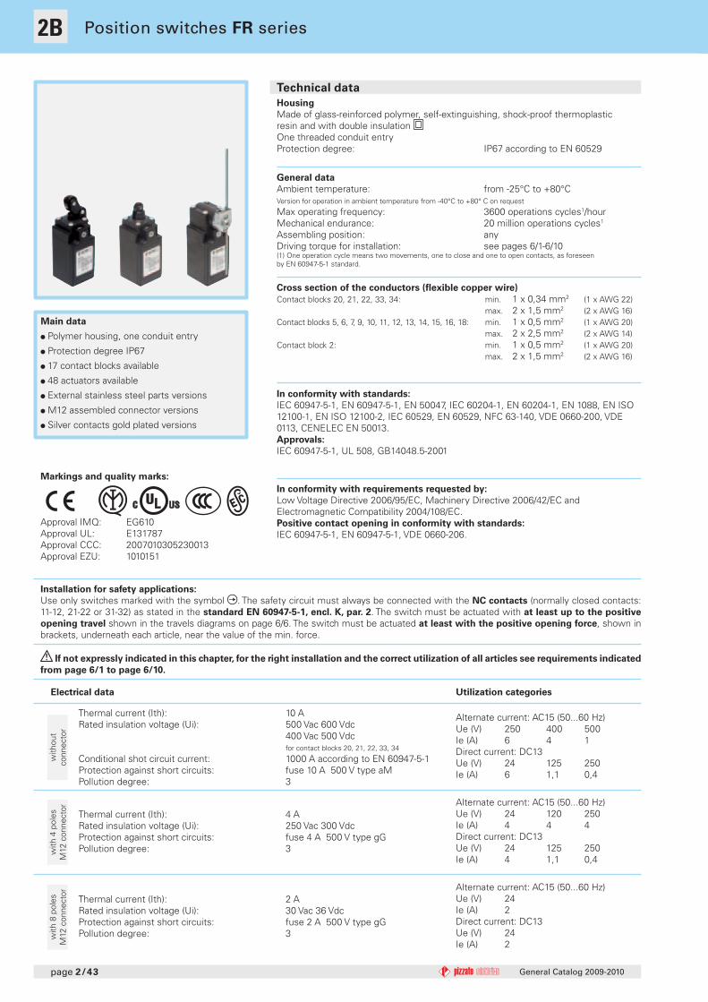
Technical data
General Catalog 2009-2010
Position switches FR series
Main data
Polymer housing, one conduit entry
Protection degree IP67
17 contact blocks available
48 actuators available
External stainless steel parts versions
M12 assembled connector versions
Silver contacts gold plated versions
Electrical data Utilization categories
Alternate current: AC15 (50...60 Hz)Ue (V) 250 400 500Ie (A) 6 4 1Direct current: DC13Ue (V) 24 125 250Ie (A) 6 1,1 0,4
Alternate current: AC15 (50...60 Hz)Ue (V) 24 120 250Ie (A) 4 4 4Direct current: DC13Ue (V) 24 125 250Ie (A) 4 1,1 0,4
Thermal current (Ith): 4 ARated insulation voltage (Ui): 250 Vac 300 VdcProtection against short circuits: fuse 4 A 500 V type gGPollution degree: 3w
ith 4
pol
esM
12 c
onne
ctor
Thermal current (Ith): 2 ARated insulation voltage (Ui): 30 Vac 36 VdcProtection against short circuits: fuse 2 A 500 V type gGPollution degree: 3w
ith 8
pol
esM
12 c
onne
ctor
Alternate current: AC15 (50...60 Hz)Ue (V) 24 Ie (A) 2 Direct current: DC13Ue (V) 24 Ie (A) 2
with
out
conn
ecto
r
General data
Ambient temperature: from -25°C to +80°CVersion for operation in ambient temperature from -40°C to +80° C on request
Max operating frequency: 3600 operations cycles1/hourMechanical endurance: 20 million operations cycles1
Assembling position: anyDriving torque for installation: see pages 6/1-6/10(1) One operation cycle means two movements, one to close and one to open contacts, as foreseenby EN 60947-5-1 standard.
Cross section of the conductors (fl exible copper wire)
Contact blocks 20, 21, 22, 33, 34: min. 1 x 0,34 mm2 (1 x AWG 22) max. 2 x 1,5 mm2 (2 x AWG 16)Contact blocks 5, 6, 7, 9, 10, 11, 12, 13, 14, 15, 16, 18: min. 1 x 0,5 mm2 (1 x AWG 20) max. 2 x 2,5 mm2 (2 x AWG 14)Contact block 2: min. 1 x 0,5 mm2 (1 x AWG 20) max. 2 x 1,5 mm2 (2 x AWG 16)
Housing
Made of glass-reinforced polymer, self-extinguishing, shock-proof thermoplasticresin and with double insulation One threaded conduit entryProtection degree: IP67 according to EN 60529
Markings and quality marks:
Approval IMQ: EG610Approval UL: E131787Approval CCC: 2007010305230013Approval EZU: 1010151
Installation for safety applications:
Use only switches marked with the symbol . The safety circuit must always be connected with the NC contacts (normally closed contacts: 11-12, 21-22 or 31-32) as stated in the standard EN 60947-5-1, encl. K, par. 2. The switch must be actuated with at least up to the positive
opening travel shown in the travels diagrams on page 6/6. The switch must be actuated at least with the positive opening force, shown in brackets, underneath each article, near the value of the min. force.
In conformity with requirements requested by:
Low Voltage Directive 2006/95/EC, Machinery Directive 2006/42/EC and Electromagnetic Compatibility 2004/108/EC.Positive contact opening in conformity with standards:
IEC 60947-5-1, EN 60947-5-1, VDE 0660-206.
In conformity with standards:
IEC 60947-5-1, EN 60947-5-1, EN 50047, IEC 60204-1, EN 60204-1, EN 1088, EN ISO 12100-1, EN ISO 12100-2, IEC 60529, EN 60529, NFC 63-140, VDE 0660-200, VDE 0113, CENELEC EN 50013.Approvals:
IEC 60947-5-1, UL 508, GB14048.5-2001
If not expressly indicated in this chapter, for the right installation and the correct utilization of all articles see requirements indicated
from page 6/1 to page 6/10.
Thermal current (Ith): 10 ARated insulation voltage (Ui): 500 Vac 600 Vdc 400 Vac 500 Vdc for contact blocks 20, 21, 22, 33, 34
Conditional shot circuit current: 1000 A according to EN 60947-5-1Protection against short circuits: fuse 10 A 500 V type aMPollution degree: 3
1B
1
1A
2
2A
2B
2C
2D
2E
3
3A
3B
3C
4
4A
4B
4C
4D
4E
4F
4G
4H
5
6
2B
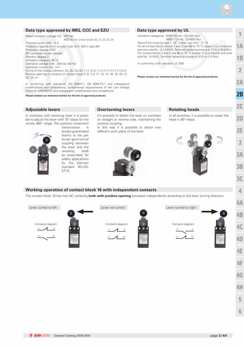
11 12
21 22
11 12
21 22
11 12
21 22
10°
page 2/44General Catalog 2009-2010
In all switches, it is possible to rotate the head in 90° steps.
Adjustable levers
Lever not turned
Working operation of contact block 16 with independent contacts
The contact block 16 has two NC contacts, both with positive opening activated independently according to the lever turning direction.
Lever turned to rightLever turned to left
Contacts diagram Contacts diagram Contacts diagram
In switches with revolving lever it is possi-ble to adjust the lever with 10° steps for the whole 360° range. The positive movement
transmission is always guaranteed thanks to the par-ticular geometrical coupling between the lever and the revolving shaft as prescribed for safety applications by the German standard BG-GS-ET-15.
Overturning levers Rotating heads
It’s possible to fasten the lever on switches on straight or reverse side, maintaining the positive coupling.In this way it is possible to obtain two different work plans of the lever.
Please contact our technical service for the list of approved products.
Please contact our technical service for the list of approved products.
Data type approved by IMQ, CCC and EZU Data type approved by UL
Utilization categories Q300 (69 VA, 125-250 Vdc) A600 (720 VA, 120-600 Vac)Data of the housing type 1, 4X “indoor use only”, 12, 13 For all contact blocks except 2 and 3 use 60 or 75 °C copper (Cu) conductor and wire size No. 12-14 AWG. Terminal tightening torque of 7,1 lb in (0.8 Nm).For contact blocks 2 and 3 use 60 or 75 °C copper (Cu) conductor and wire size No. 14 AWG. Terminal tightening torque of 12 lb in (1.4 Nm).
In conformity with standard: UL 508
Rated insulation voltage (Ui): 500 Vac 400 Vac for contact blocks 20, 21, 22, 33, 34 Thermal current (Ith): 10 AProtection against short circuits: fuse 10 A 500 V type aMProtection degree: IP67MV terminals (screw clamps)Pollution degree 3Utilization category: AC15Operation voltage (Ue): 400 Vac (50 Hz)Operation current (Ie): 3 AForms of the contact element: Za, Zb, Za+Za, Y+Y, X+X, Y+Y+X, Y+Y+Y, Y+X+XPositive opening of contacts on contact block 5, 6, 7, 9, 11, 13, 14, 16, 18, 20, 21, 22, 33, 34
In conformity with standards: EN 60947-1, EN 60947-5-1 and subsequent modifi cations and completions, fundamental requirements of the Low Voltage Directive 2006/95/CE and subsequent modifi cations and completions.
5 R
6 L
7 LO
9 L
10 L
11 R
12 R
13 LV
14 LS
15 LS
18 LA
20 L
21 L
22 L
2 R
E1
5 R
6 L
7 LO
9 L
10 L
11 R
12 R
13 LV
14 LS
15 LS
18 LA
20 L
21 L
22 L
2 R
E1
2B
321.4
2022 24.2
51.572
.9
12.2
30.8 30.8
14.2
4.2x7.2Ø 8
Ø 12
30.830.8
3
2022
24.2
Ø 8
21
12.2
51.572
.5
14.2
4.2x7.2
2022 24.2
51.5
30.8 30.8
14.2
40.1
91.6 12.2
14
3
5.5
4.2x7.2
2022 24.2
51.5
30.8 30.8
14.2
40.1
91.6 12.2
14
3
5.5
4.2x7.2
51.5
2022
31
30.8
11
82.5
14.2
24.2
30.8
3.6
3
4.2x7.2
12.2
2022 24.2
51.5
12.2
30.8 30.8
14.2
340.5
92
14
12.4
5.5
4.2x7.2
2022 24.2
51.5
12.2
30.8 30.8
14.2
340.5
92
14
12.4
5.5
4.2x7.2
30.830.8
3
2022 24.2
12.2
14.2
5.4
22
51.5
5210
3.5
17 - 20 - 2329 - 32 - 35
4.2x7.2
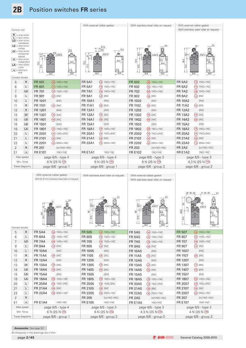
FR 501 1NO+1NC
FR 601 1NO+1NC
FR 701 1NO+1NC
FR 901 2NC
FR 1001 2NO
FR 1101 2NC
FR 1201 2NO
FR 1301 2NC
FR 1401 2NC
FR 1501 2NO
FR 1801 1NO+1NC
FR 2001 1NO+2NC
FR 2101 3NC
FR 2201 2NO+1NC
FR 201 2x(1NO-1NC)
FR E101 1NO-1NC
FR 5A5 1NO+1NC
FR 6A5 1NO+1NC
FR 7A5 1NO+1NC
FR 9A5 2NC
FR 10A5 2NO
FR 11A5 2NC
FR 12A5 2NO
FR 13A5 2NC
FR 14A5 2NC
FR 15A5 2NO
FR 18A5 1NO+1NC
FR 20A5 1NO+2NC
FR 21A5 3NC
FR 22A5 2NO+1NC
FR 2A5 2x(1NO-1NC)
FR E1A5 1NO-1NC
FR 502 1NO+1NC
FR 602 1NO+1NC
FR 702 1NO+1NC
FR 902 2NC
FR 1002 2NO
FR 1102 2NC
FR 1202 2NO
FR 1302 2NC
FR 1402 2NC
FR 1502 2NO
FR 1802 1NO+1NC
FR 2002 1NO+2NC
FR 2102 3NC
FR 2202 2NO+1NC
FR 202 2x(1NO-1NC)
FR E102 1NO-1NC
FR 5A2 1NO+1NC
FR 6A2 1NO+1NC
FR 7A2 1NO+1NC
FR 9A2 2NC
FR 10A2 2NO
FR 11A2 2NC
FR 12A2 2NO
FR 13A2 2NC
FR 14A2 2NC
FR 15A2 2NO
FR 18A2 1NO+1NC
FR 20A2 1NO+2NC
FR 21A2 3NC
FR 22A2 2NO+1NC
FR 2A2 2x(1NO-1NC)
FR E1A2 1NO-1NC
FR 505 1NO+1NC
FR 605 1NO+1NC
FR 705 1NO+1NC
FR 905 2NC
FR 1005 2NO
FR 1105 2NC
FR 1205 2NO
FR 1305 2NC
FR 1405 2NC
FR 1505 2NO
FR 1805 1NO+1NC
FR 2005 1NO+2NC
FR 2105 3NC
FR 2205 2NO+1NC
FR 205 2x(1NO-1NC)
FR E105 1NO-1NC
FR 5A1 1NO+1NC
FR 6A1 1NO+1NC
FR 7A1 1NO+1NC
FR 9A1 2NC
FR 10A1 2NO
FR 11A1 2NC
FR 12A1 2NO
FR 13A1 2NC
FR 14A1 2NC
FR 15A1 2NO
FR 18A1 1NO+1NC
FR 20A1 1NO+2NC
FR 21A1 3NC
FR 22A1 2NO+1NC
FR E1A1 1NO-1NC
FR 507 1NO+1NC
FR 607 1NO+1NC
FR 707 1NO+1NC
FR 907 2NC
FR 1007 2NO
FR 1107 2NC
FR 1207 2NO
FR 1307 2NC
FR 1407 2NC
FR 1507 2NO
FR 1807 1NO+1NC
FR 2007 1NO+2NC
FR 2107 3NC
FR 2207 2NO+1NC
FR 207 2x(1NO-1NC)
FR E107 1NO-1NC
FR 5A4 1NO+1NC
FR 6A4 1NO+1NC
FR 7A4 1NO+1NC
FR 9A4 2NC
FR 10A4 2NO
FR 11A4 2NC
FR 12A4 2NO
FR 13A4 2NC
FR 14A4 2NC
FR 15A4 2NO
FR 18A4 1NO+1NC
FR 20A4 1NO+2NC
FR 21A4 3NC
FR 22A4 2NO+1NC
FR E1A4 1NO-1NC
page 2/45
Max speed
Min. force
Travel diagrams
Max speed
Min. force
Travel diagrams
General Catalog 2009-2010
Accessories See page 5/1
Position switches FR series
Contacts type:
R = snap actionL = slow action
LO = slow action overlappedLS = slow action
shiftedLV = slow action
shifted and spacedLI = slow action
independent
LA = slow action closer
= electronic PNP
Contact blocks
Contact blocks
page 6/5 - type 46 N (25 N )
page 6/6 - group 1
page 6/5 - type 36 N (25 N )
page 6/6 - group 2
page 6/5 - type 36 N (25 N )
page 6/6 - group 2
page 6/5 - type 34,3 N (25 N )
page 6/6 - group 2
page 6/5 - type 34,3 N (25 N )
page 6/6 - group 2
page 6/5 - type 48 N (25 N )
page 6/6 - group 1
page 6/5 - type 34 N (25 N )
page 6/6 - group 3
With external rubber gasket With external rubber gasket
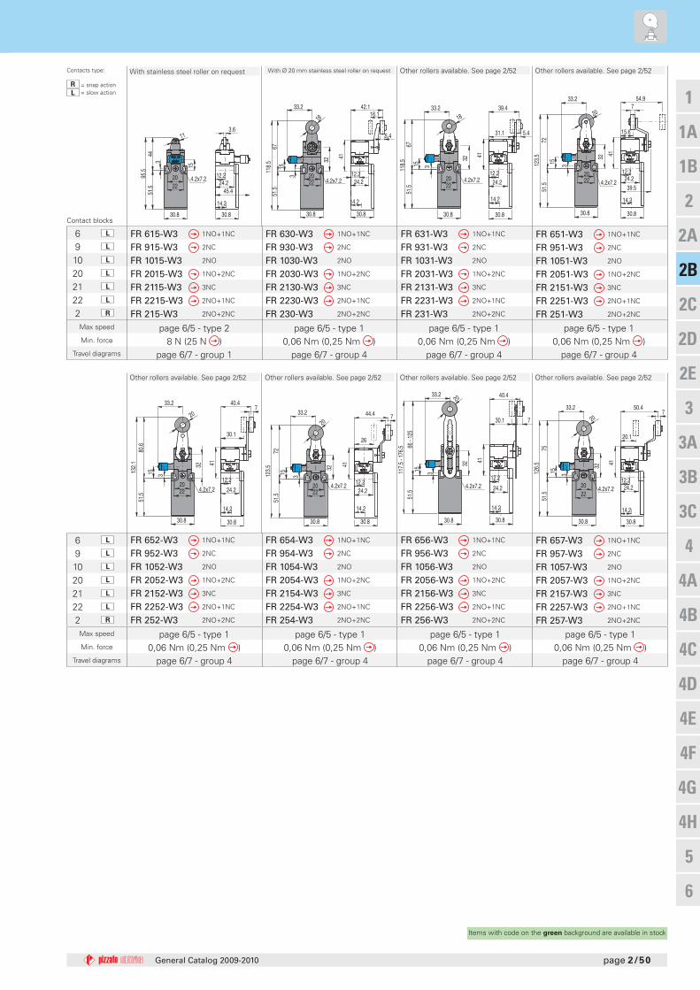
With stainless steel roller on request
With stainless steel roller on request
All measures in the drawings are in mm
With external rubber gasket
With stainless steel roller on request
With stainless steel roller on request
page 6/5 - type 46 N (25 N )
page 6/6 - group 1
With external rubber gasket
With Ø 12 mm stainless steel roller on request

5 R
6 L
7 LO
9 L
10 L
11 R
12 R
13 LV
14 LS
15 LS
18 LA
20 L
21 L
22 L
2 R
E1
5 R
6 L
7 LO
9 L
10 L
11 R
12 R
13 LV
14 LS
15 LS
18 LA
20 L
21 L
22 L
2 R
E1
1B
1
1A
2
2A
2B
2C
2D
2E
3
3A
3B
3C
4
4A
4B
4C
4D
4E
4F
4G
4H
5
6
2B
M 18x1
4
3.812
30.830.8
3
2022 24.2
25.2
8.4
51.5
100.
1
14.2
12.2
24
4.2x7.2
3
2022 24.2
51.5
12.2
30.8 30.8
27.9
79.4
14.2
R 13
4.2x7.2
3.611
30.830.8
3
2022 24.2
3151
.582
.5 12.2
14.2
4.2x7.2
3.812
30.830.8
3
2022 24.2
31.5
51.5
83
12.2
14.2
4.2x7.2
30.830.8
3
2022 24.2
12.2
14.2
5.4
2251
.552
103.
5
17 - 20 - 2329 - 32 - 35
4.2x7.2
2022 24.2
51.5
12.2
30.8 30.8
14.2
330.1
Ø 10
81.6
4.2x7.2M12x1
Ø 7.4
30.830.8
5.8
2.514
.2
14
12.2
87.5
14.2
M 18x1
4
Ø 8
25.2
30.830.8
3
2022 24.2
8.4
51.5
12.2100.
1
14.2
24
4.2x7.2
FR 5A7 1NO+1NC
FR 6A7 1NO+1NC
FR 7A7 1NO+1NC
FR 9A7 2NC
FR 10A7 2NO
FR 11A7 2NC
FR 12A7 2NO
FR 13A7 2NC
FR 14A7 2NC
FR 15A7 2NO
FR 18A7 1NO+1NC
FR 20A7 1NO+2NC
FR 21A7 3NC
FR 22A7 2NO+1NC
FR 2A7 2x(1NO-1NC)
FR E1A7 1NO-1NC
FR 510 1NO+1NC
FR 610 1NO+1NC
FR 710 1NO+1NC
FR 910 2NC
FR 1010 2NO
FR 1110 2NC
FR 1210 2NO
FR 1310 2NC
FR 1410 2NC
FR 1510 2NO
FR 1810 1NO+1NC
FR 2010 1NO+2NC
FR 2110 3NC
FR 2210 2NO+1NC
FR 210 2x(1NO-1NC)
FR E110 1NO-1NC
FR 508 1NO+1NC
FR 608 1NO+1NC
FR 708 1NO+1NC
FR 908 2NC
FR 1008 2NO
FR 1108 2NC
FR 1208 2NO
FR 1308 2NC
FR 1408 2NC
FR 1508 2NO
FR 1808 1NO+1NC
FR 2008 1NO+2NC
FR 2108 3NC
FR 2208 2NO+1NC
FR 208 2x(1NO-1NC)
FR E108 1NO-1NC
FR 512 1NO+1NC
FR 612 1NO+1NC
FR 712 1NO+1NC
FR 912 2NC
FR 1012 2NO
FR 1112 2NC
FR 1212 2NO
FR 1312 2NC
FR 1412 2NC
FR 1512 2NO
FR 1812 1NO+1NC
FR 2012 1NO+2NC
FR 2112 3NC
FR 2212 2NO+1NC
FR 212 2x(1NO-1NC)
FR E112 1NO-1NC
FR 513 1NO+1NC
FR 613 1NO+1NC
FR 713 1NO+1NC
FR 913 2NC
FR 1013 2NO
FR 1113 2NC
FR 1213 2NO
FR 1313 2NC
FR 1413 2NC
FR 1513 2NO
FR 1813 1NO+1NC
FR 2013 1NO+2NC
FR 2113 3NC
FR 2213 2NO+1NC
FR 213 2x(1NO-1NC)
FR E113 1NO-1NC
FR 515 1NO+1NC
FR 615 1NO+1NC
FR 715 1NO+1NC
FR 915 2NC
FR 1015 2NO
FR 1115 2NC
FR 1215 2NO
FR 1315 2NC
FR 1415 2NC
FR 1515 2NO
FR 1815 1NO+1NC
FR 2015 1NO+2NC
FR 2115 3NC
FR 2215 2NO+1NC
FR 215 2x(1NO-1NC)
FR E115 1NO-1NC
FR 514 1NO+1NC
FR 614 1NO+1NC
FR 714 1NO+1NC
FR 914 2NC
FR 1014 2NO
FR 1114 2NC
FR 1214 2NO
FR 1314 2NC
FR 1414 2NC
FR 1514 2NO
FR 1814 1NO+1NC
FR 2014 1NO+2NC
FR 2114 3NC
FR 2214 2NO+1NC
FR 214 2x(1NO-1NC)
FR E114 1NO-1NC
FR 515-1 1NO+1NC
FR 615-1 1NO+1NC
FR 715-1 1NO+1NC
FR 915-1 2NC
FR 1015-1 2NO
FR 1115-1 2NC
FR 1215-1 2NO
FR 1315-1 2NC
FR 1415-1 2NC
FR 1515-1 2NO
FR 1815-1 1NO+1NC
FR 2015-1 1NO+2NC
FR 2115-1 3NC
FR 2215-1 2NO+1NC
FR 215-1 2x(1NO-1NC)
FR E115-1 1NO-1NC
page 2/46
Max speed
Min. force
Travel diagrams
Max speed
Min. force
Travel diagrams
General Catalog 2009-2010
Items with code on the green background are available in stock
Contacts type:
R = snap actionL = slow action
LO = slow action overlappedLS = slow action
shiftedLV = slow action
shifted and spacedLI = slow action
independent
LA = slow action closer
= electronic PNP
Contact blocks
Contact blocks
page 6/5 - type 33 N (25 N )
page 6/6 - group 3
page 6/5 - type 28 N (25 N )
page 6/6 - group 1
page 6/5 - type 48 N (25 N )
page 6/6 - group 1
page 6/5 - type 48 N (25 N )
page 6/6 - group 1
page 6/5 - type 48 N (25 N )
page 6/6 - group 1
page 6/5 - type 28 N (25 N )
page 6/6 - group 1
page 6/5 - type 48 N (25 N )
page 6/6 - group 1
page 6/5 - type 28 N (25 N )
page 6/6 - group 1
With external rubber gasket Fixed only by threaded head in vertical position
With external rubber gasket
Ø 12 mm stainless steel rollerØ 11 mm polymer roller

5 R
6 L
7 LO
9 L
10 L
11 R
12 R
13 LV
14 LS
15 LS
16 LI
18 LA
20 L
21 L
22 L
2 R
E1
5 R
6 L
7 LO
9 L
10 L
11 R
12 R
13 LV
14 LS
15 LS
18 LA
20 L
21 L
22 L
2 R
E1
2B
2022 24.2
51.5
12.2
30.8 30.8
14.2
3
Ø 7.5
2412
717
8.5
4.2x7.2
4.2x7.2
14.2
28
41.516.5
24.2
30.8
5.4
2022
3
51.5
1954
30.8
18
105.
5
18
2022
5451
.510
5.5
19 3
30.8
4.2x7.2
14.2
28
39.4
31.1
5.4
30.8
24.2
30.830.8
3
2022
24.2
3x3x125
4.5
1938
- 13
5
28
35
51.5
89.5
- 18
6.5
14.2
4.2x
7.2
2022 24.2
51.5
30.8 30.8
14.2
3
12.2
40.5
92
20 3.6
4.2x7.2
12
30.830.8
2013 M12x1
3.8
101
12.2
14.2
3
17
2022 24.2
51.5
12.2
30.8 30.8
14.2
324
55
Ø 7
124
175.
5
4.2x7.2
2022 24.2
51.5
12.2
30.8 30.8
14.2
324
141
192.
5
Ø 1.2
4.2x7.2
FR 520 1NO+1NC
FR 1020 2NO
FR 1220 2NO
FR 1820 1NO+1NC
FR 2020 1NO+2NC
FR 2120 3NC
FR 2220 2NO+1NC
FR 220 2x(1NO-1NC)
FR E120 1NO-1NC
FR 521 1NO+1NC
FR 1021 2NO
FR 1221 2NO
FR 1821 1NO+1NC
FR 2021 1NO+2NC
FR 2121 3NC
FR 2221 2NO+1NC
FR 221 2x(1NO-1NC)
FR E121 1NO-1NC
FR 530 1NO+1NC
FR 630 1NO+1NC
FR 730 1NO+1NC
FR 930 2NC
FR 1030 2NO
FR 1130 2NC
FR 1230 2NO
FR 1330 2NC
FR 1430 2NC
FR 1530 2NO
FR 1630 2NC
FR 1830 1NO+1NC
FR 2030 1NO+2NC
FR 2130 3NC
FR 2230 2NO+1NC
FR 230 2x(1NO-1NC)
FR E130 1NO-1NC
FR 531 1NO+1NC
FR 631 1NO+1NC
FR 731 1NO+1NC
FR 931 2NC
FR 1031 2NO
FR 1131 2NC
FR 1231 2NO
FR 1331 2NC
FR 1431 2NC
FR 1531 2NO
FR 1631 2NC
FR 1831 1NO+1NC
FR 2031 1NO+2NC
FR 2131 3NC
FR 2231 2NO+1NC
FR 231 2x(1NO-1NC)
FR E131 1NO-1NC
FR 533 1NO+1NC
FR 633 1NO+1NC
FR 733 1NO+1NC
FR 933 2NC
FR 1033 2NO
FR 1133 2NC
FR 1233 2NO
FR 1333 2NC
FR 1433 2NC
FR 1533 2NO
FR 1633 2NC
FR 1833 1NO+1NC
FR 2033 1NO+2NC
FR 2133 3NC
FR 2233 2NO+1NC
FR 233 2x(1NO-1NC)
FR E133 1NO-1NC
FR 525 1NO+1NC
FR 1025 2NO
FR 1225 2NO
FR 1825 1NO+1NC
FR 2025 1NO+2NC
FR 2125 3NC
FR 2225 2NO+1NC
FR 225 2x(1NO-1NC)
FR E125 1NO-1NC
FR 517 1NO+1NC
FR 617 1NO+1NC
FR 717 1NO+1NC
FR 917 2NC
FR 1017 2NO
FR 1117 2NC
FR 1217 2NO
FR 1317 2NC
FR 1417 2NC
FR 1517 2NO
FR 1817 1NO+1NC
FR 2017 1NO+2NC
FR 2117 3NC
FR 2217 2NO+1NC
FR 217 2x(1NO-1NC)
FR E117 1NO-1NC
FR 516 1NO+1NC
FR 616 1NO+1NC
FR 716 1NO+1NC
FR 916 2NC
FR 1016 2NO
FR 1116 2NC
FR 1216 2NO
FR 1316 2NC
FR 1416 2NC
FR 1516 2NO
FR 1816 1NO+1NC
FR 2016 1NO+2NC
FR 2116 3NC
FR 2216 2NO+1NC
FR 216 2x(1NO-1NC)
FR E116 1NO-1NC
page 2/47
Max speed
Min. force
Travel diagrams
Max speed
Min. force
Travel diagrams
General Catalog 2009-2010
Accessories See page 5/1
Position switches FR series
Contacts type:
R = snap actionL = slow action
LO = slow action overlappedLS = slow action
shiftedLV = slow action
shifted and spacedLI = slow action
independent
LA = slow action closer
= electronic PNP
Contact blocks
Contact blocks
3x3 mm square rod
1 m/s 0,07 Nm
page 6/6 - group 4
1 m/s 0,07 Nm
page 6/6 - group 4
page 6/5 - type 10,06 Nm (0,25 Nm )
page 6/6 - group 5
1 m/s 0,12 Nm
page 6/6 - group 4
page 6/5 - type 10,06 Nm (0,25 Nm )
page 6/6 - group 5
1,5 m/s 0,06 Nm
page 6/6 - group 5
page 6/5 - type 28 N (25 N )
page 6/6 - group 1
Fixed only by threaded head in vertical position
Other rollers available. See page 2/52
page 6/5 - type 28 N (25 N )
page 6/6 - group 1
With external rubber gasket With external rubber gasket
With external rubber gasket With Ø 20 mm stainless steel roller on request
5 R
6 L
7 LO
9 L
10 L
11 R
12 R
13 LV
14 LS
15 LS
16 LI
18 LA
20 L
21 L
22 L
2 R
E1
5 R
6 L
7 LO
9 L
10 L
11 R
12 R
13 LV
14 LS
15 LS
16 LI
18 LA
20 L
21 L
22 L
2 R
E1
1B
1
1A
2
2A
2B
2C
2D
2E
3
3A
3B
3C
4
4A
4B
4C
4D
4E
4F
4G
4H
5
6
2B
30.830.8
3
2022
24.2
28
51.5
19
27.527.5
Ø 9
56.5
99.3
150.
8
14.2
41.5
4.2x
7.2
30.830.8
3
2022
24.2
19 28
7
20
25
44
5911
0.5
51.5
14.2
4.2x
7.2
30.830.8
3
2022
24.2
20
53 -
112
28
729
40
51.5
104.
5 - 1
63.5
19
14.2
4.2x
7.2
30.830.8
3
2022
24.2
2053
- 11
2
28
729
40
51.5
104.
5 - 1
63.5
19
14.2
4.2x
7.2
55
30.830.8
3
2022
24.2
28
51.5
19
27.5
125
176.
5
14.24.
2x7.
2
Ø 7.3
41.5
30.830.8
3
2022
24.2
Ø3x125
4.5
1938
- 13
5
28
35
51.5
89.5
- 18
6.5
14.2
4.2x
7.2
30.830.8
3
2022
24.2
19 28
51.5
7
5911
0.5
14.2
14.6
54
4.2x
7.2
20
7
20
30.830.8
3
2022
24.2
19 28
29
40
51.5
14.2
67.6
119.
1
4.2x
7.2
FR 534 1NO+1NC
FR 634 1NO+1NC
FR 734 1NO+1NC
FR 934 2NC
FR 1034 2NO
FR 1134 2NC
FR 1234 2NO
FR 1334 2NC
FR 1434 2NC
FR 1534 2NO
FR 1634 2NC
FR 1834 1NO+1NC
FR 2034 1NO+2NC
FR 2134 3NC
FR 2234 2NO+1NC
FR 234 2x(1NO-1NC)
FR E134 1NO-1NC
FR 550 1NO+1NC
FR 650 1NO+1NC
FR 750 1NO+1NC
FR 950 2NC
FR 1050 2NO
FR 1150 2NC
FR 1250 2NO
FR 1350 2NC
FR 1450 2NC
FR 1550 2NO
FR 1650 2NC
FR 1850 1NO+1NC
FR 2050 1NO+2NC
FR 2150 3NC
FR 2250 2NO+1NC
FR 250 2x(1NO-1NC)
FR E150 1NO-1NC
FR 555 (1) 1NO+1NC
FR 655 (1) 1NO+1NC
FR 755 (1) 1NO+1NC
FR 955 (1) 2NC
FR 1055 2NO
FR 1155 (1) 2NC
FR 1255 2NO
FR 1355 (1) 2NC
FR 1455 (1) 2NC
FR 1555 2NO
FR 1655 (1) 2NC
FR 1855 (1) 1NO+1NC
FR 2055 (1) 1NO+2NC
FR 2155 (1) 3NC
FR 2255 (1) 2NO+1NC
FR 255 2x(1NO-1NC)
FR E155 1NO-1NC
FR 556 1NO+1NC
FR 656 1NO+1NC
FR 756 1NO+1NC
FR 956 2NC
FR 1056 2NO
FR 1156 2NC
FR 1256 2NO
FR 1356 2NC
FR 1456 2NC
FR 1556 2NO
FR 1656 2NC
FR 1856 1NO+1NC
FR 2056 1NO+2NC
FR 2156 3NC
FR 2256 2NO+1NC
FR 256 2x(1NO-1NC)
FR E156 1NO-1NC
FR 554 1NO+1NC
FR 654 1NO+1NC
FR 754 1NO+1NC
FR 954 2NC
FR 1054 2NO
FR 1154 2NC
FR 1254 2NO
FR 1354 2NC
FR 1454 2NC
FR 1554 2NO
FR 1654 2NC
FR 1854 1NO+1NC
FR 2054 1NO+2NC
FR 2154 3NC
FR 2254 2NO+1NC
FR 254 2x(1NO-1NC)
FR E154 1NO-1NC
FR 553-E0V9 1NO+1NC
FR 653-E0V9 1NO+1NC
FR 753-E0V9 1NO+1NC
FR 953-E0V9 2NC
FR 1053-E0V9 2NO
FR 1253-E0V9 2NO
FR 1353-E0V9 2NC
FR 1453-E0V9 2NC
FR 1553-E0V9 2NO
FR 1853-E0V9 1NO+1NC
FR 2053-E0V9 1NO+2NC
FR 2153-E0V9 3NC
FR 2253-E0V9 2NO+1NC
FR 253-E0 2x(1NO-1NC)
FR E153-E0V9 1NO-1NC
FR 552 1NO+1NC
FR 652 1NO+1NC
FR 752 1NO+1NC
FR 952 2NC
FR 1052 2NO
FR 1152 2NC
FR 1252 2NO
FR 1352 2NC
FR 1452 2NC
FR 1552 2NO
FR 1652 2NC
FR 1852 1NO+1NC
FR 2052 1NO+2NC
FR 2152 3NC
FR 2252 2NO+1NC
FR 252 2x(1NO-1NC)
FR E152 1NO-1NC
FR 551 1NO+1NC
FR 651 1NO+1NC
FR 751 1NO+1NC
FR 951 2NC
FR 1051 2NO
FR 1151 2NC
FR 1251 2NO
FR 1351 2NC
FR 1451 2NC
FR 1551 2NO
FR 1651 2NC
FR 1851 1NO+1NC
FR 2051 1NO+2NC
FR 2151 3NC
FR 2251 2NO+1NC
FR 251 2x(1NO-1NC)
FR E151 1NO-1NC
page 2/48
Max speed
Min. force
Travel diagrams
Max speed
Min. force
Travel diagrams
General Catalog 2009-2010
Items with code on the green background are available in stock
Contacts type:
R = snap actionL = slow action
LO = slow action overlappedLS = slow action
shiftedLV = slow action
shifted and spacedLI = slow action
independent
LA = slow action closer
= electronic PNP
Contact blocks
Contact blocks
Porcelain roller
Ø 3 mm stainless steel round rod
1,5 m/s 0,06 Nm
page 6/6 - group 5
1,5 m/s 0,06 Nm
page 6/6 - group 5
page 6/5 - type 10,06 Nm (0,25 Nm )
page 6/6 - group 5
page 6/5 - type 10,06 Nm (0,25 Nm )
page 6/6 - group 5
page 6/5 - type 10,06 Nm (0,25 Nm )
page 6/6 - group 5
0,5 m/s0,03 Nm (0,25 Nm )
page 6/6 - group 6
page 6/5 - type 10,06 Nm (0,25 Nm )
page 6/6 - group 5
page 6/5 - type 10,06 Nm (0,25 Nm )
page 6/6 - group 5
(1) Positive opening only with lever adjusted on the max. See page 2/51
Other rollers available. See page 2/52 Other rollers available. See page 2/52
Other rollers available. See page 2/52Other rollers available. See page 2/52Other rollers available. See page 2/52

2B
5 R
6 L
7 LO
9 L
10 L
11 R
12 R
13 LV
14 LS
15 LS
16 LI
18 LA
20 L
21 L
22 L
2 R
E1
6 L
9 L
10 L
20 L
21 L
22 L
2 R
3
2022
24.2
19 28
7
20
19
5051
.562
30.830.8
113.
5
14.2
4.2x
7.2
30.830.8
3
22
24.2
20
28
36.5
51.5
38 -
208
89.5
- 25
9.5
19
14.2
4.2X
7.2
Ø6x200
10
2022 24.2
51.5
30.8 30.8
14.2
38.8
15.3
108.
6
12.2
3 4.2x7.2
30.830.8
3
2022 24.2
37
Ø 835.5
12.2
51.5
88.5
14.2
4.2x
7.2
2022
3
51.5
15
34.4
30.8
Ø 8
85.9
4.2x7.2
14.2
12.2
30.8
24.245.4
2022
351
.553
.1
15
30.8
14
104.
6
4.2x7.2
14.2
12.2
30.8
24.245.4
5.5
2022
351
.553
.5
15
30.8
14
12.4105
4.2x7.2
14.2
12.2
30.8
24.245.4
5.5
2022
351
.5
15
30.8
4.2x7.2
14.2
12.2
30.8
24.245.4
29 - 32 - 35 17 - 20 - 23
6511
6.5
22
5.4
FR 576 1NO+1NC
FR 676 1NO+1NC
FR 776 1NO+1NC
FR 976 2NO
FR 1076 2NC
FR 1176 2NO
FR 1276 2NC
FR 1376 2NO
FR 1476 2NO
FR 1576 2NC
FR 1876 1NO+1NC
FR 2076 2NO+1NC
FR 2176 3NO
FR 2276 1NO+2NC
FR 276 2x(1NO-1NC)
FR 601-W3 1NO+1NC
FR 901-W3 2NC
FR 1001-W3 2NO
FR 2001-W3 1NO+2NC
FR 2101-W3 3NC
FR 2201-W3 2NO+1NC
FR 201-W3 2NO+2NC
FR 602-W3 1NO+1NC
FR 902-W3 2NC
FR 1002-W3 2NO
FR 2002-W3 1NO+2NC
FR 2102-W3 3NC
FR 2202-W3 2NO+1NC
FR 202-W3 2NO+2NC
FR 605-W3 1NO+1NC
FR 905-W3 2NC
FR 1005-W3 2NO
FR 2005-W3 1NO+2NC
FR 2105-W3 3NC
FR 2205-W3 2NO+1NC
FR 205-W3 2NO+2NC
FR 607-W3 1NO+1NC
FR 907-W3 2NC
FR 1007-W3 2NO
FR 2007-W3 1NO+2NC
FR 2107-W3 3NC
FR 2207-W3 2NO+1NC
FR 207-W3 2NO+2NC
FR 569 1NO+1NC
FR 669 1NO+1NC
FR 769 1NO+1NC
FR 969 2NC
FR 1069 2NO
FR 1169 2NC
FR 1269 2NO
FR 1369 2NC
FR 1469 2NC
FR 1569 2NO
FR 1669 2NC
FR 1869 1NO+1NC
FR 2069 1NO+2NC
FR 2169 3NC
FR 2269 2NO+1NC
FR 269 2x(1NO-1NC)
FR E169 1NO-1NC
FR 557 1NO+1NC
FR 657 1NO+1NC
FR 757 1NO+1NC
FR 957 2NC
FR 1057 2NO
FR 1157 2NC
FR 1257 2NO
FR 1357 2NC
FR 1457 2NC
FR 1557 2NO
FR 1657 2NC
FR 1857 1NO+1NC
FR 2057 1NO+2NC
FR 2157 3NC
FR 2257 2NO+1NC
FR 257 2x(1NO-1NC)
FR E157 1NO-1NC
page 2/49
Max speed
Min. force
Travel diagrams
Max speed
Min. force
Travel diagrams
General Catalog 2009-2010
Accessories See page 5/1
Position switches FR series
Position switches FR series with reset
FR 501-72 1NO+1NC
FR 1001-72 2NO
This switch can be installed on doors of electrical boards. It is used to switch on possible signal devices, once the door is open (e.g. three-phase fl ashing devices, etc.)The operator assigned to the board maintenance may simulate the closing of the door by pushing the blue push button. At the end of the maintenance the functionality of the switch will be automatically restablished easily by closing the door of the board.
Fiber glass rod
page 6/5 - type 48 N (25 N )
page 6/6 - group 1
page 6/5 - type 48 N (25 N )
page 6/7 - group 1
page 6/5 - type 34 N (25 N )
page 6/7 - group 3
page 6/5 - type 36 N (25 N )
page 6/7 - group 2
page 6/5 - type 36 N (25 N )
page 6/7 - group 2
Rope switches for signalling
1,5 m/s0,06 Nm
page 6/6 - group 5
0,5 m/sinitial 20 N - fi nal 40 N
page 6/6 - group 7
With stainless steel roller on requestWith stainless steel roller on request
Pizzato Elettrica has developed an innovative reset device code W3 to make perfectly simultaneous the actuator and the contact block tripping. The new device is a block inserted between the switch body and the head, and could be rotated independently from this last one. This new device has following advantages:* The reset device integrate in any standard actuation head * Contact blocks with snap action are no more necessary because the tripping movement is made by the reset device itself* Unlike some previous versions, the reset device can be rotated independently from the head for the maximum fl exibility during the assembling.
Contact blocks
Contacts type:
R = snap actionL = slow action
LO = slow action overlappedLS = slow action
shiftedLV = slow action
shifted and spacedLI = slow action
independent
LA = slow action closer
= electronic PNP
Contact blocks
page 6/5 - type 10,06 Nm (0,25 Nm )
page 6/6 - group 5
Other rollers available. See page 2/52
6 L
9 L
10 L
20 L
21 L
22 L
2 R
6 L
9 L
10 L
20 L
21 L
22 L
2 R
1B
1
1A
2
2A
2B
2C
2D
2E
3
3A
3B
3C
4
4A
4B
4C
4D
4E
4F
4G
4H
5
6
2B
2022
351
.5
15
30.8
1195
.544
4.2x7.2
14.2
12.224.2
3.6
45.4
30.8
2022
3
51.5
15
32
33.2
30.8
18
6711
8.5
4.2x7.2
14.2
12.2
42.116.1
41
30.8
24.2
5.4
2022
3
51.5
33.2
1567
32
30.8
18
118.
5
4.2x7.2
14.2
12.2
41
30.8
24.2
5.4
39.4
31.1
2022
3
51.5
33.2
15
30.8
4.2x7.2
14.2
12.2
41
30.8
24.2
20
7212
3.5 32
54.9
15.6
7
39.5
2022
3
51.5
33.2
15
30.8
4.2x7.2
14.2
12.2
41
30.8
24.2
20
80.6
132.
1 32
40.4
30.1
7
2022
3
51.5
33.2
15
30.8
4.2x7.2
14.2
12.2
41
30.8
24.2
20
7212
3.5 32
26
44.4 7
2022
3
51.5
15
30.8
4.2x7.2
14.2
12.241
30.8
24.2
20
66 -
125
117.
5 - 1
76.5
33.2
32
30.1
40.4
7
15
2022
3
51.5
33.2
30.8
20
32
7512
6.5
4.2x7.2
14.2
12.2
41
20.1
50.4
30.8
24.2
7
FR 615-W3 1NO+1NC
FR 915-W3 2NC
FR 1015-W3 2NO
FR 2015-W3 1NO+2NC
FR 2115-W3 3NC
FR 2215-W3 2NO+1NC
FR 215-W3 2NO+2NC
FR 630-W3 1NO+1NC
FR 930-W3 2NC
FR 1030-W3 2NO
FR 2030-W3 1NO+2NC
FR 2130-W3 3NC
FR 2230-W3 2NO+1NC
FR 230-W3 2NO+2NC
FR 631-W3 1NO+1NC
FR 931-W3 2NC
FR 1031-W3 2NO
FR 2031-W3 1NO+2NC
FR 2131-W3 3NC
FR 2231-W3 2NO+1NC
FR 231-W3 2NO+2NC
FR 651-W3 1NO+1NC
FR 951-W3 2NC
FR 1051-W3 2NO
FR 2051-W3 1NO+2NC
FR 2151-W3 3NC
FR 2251-W3 2NO+1NC
FR 251-W3 2NO+2NC
FR 652-W3 1NO+1NC
FR 952-W3 2NC
FR 1052-W3 2NO
FR 2052-W3 1NO+2NC
FR 2152-W3 3NC
FR 2252-W3 2NO+1NC
FR 252-W3 2NO+2NC
FR 654-W3 1NO+1NC
FR 954-W3 2NC
FR 1054-W3 2NO
FR 2054-W3 1NO+2NC
FR 2154-W3 3NC
FR 2254-W3 2NO+1NC
FR 254-W3 2NO+2NC
FR 656-W3 1NO+1NC
FR 956-W3 2NC
FR 1056-W3 2NO
FR 2056-W3 1NO+2NC
FR 2156-W3 3NC
FR 2256-W3 2NO+1NC
FR 256-W3 2NO+2NC
FR 657-W3 1NO+1NC
FR 957-W3 2NC
FR 1057-W3 2NO
FR 2057-W3 1NO+2NC
FR 2157-W3 3NC
FR 2257-W3 2NO+1NC
FR 257-W3 2NO+2NC
page 2/50
Max speed
Min. force
Travel diagrams
Max speed
Min. force
Travel diagrams
General Catalog 2009-2010
Items with code on the green background are available in stock
page 6/5 - type 28 N (25 N )
page 6/7 - group 1
page 6/5 - type 10,06 Nm (0,25 Nm )
page 6/7 - group 4
page 6/5 - type 10,06 Nm (0,25 Nm )
page 6/7 - group 4
page 6/5 - type 10,06 Nm (0,25 Nm )
page 6/7 - group 4
With stainless steel roller on request
page 6/5 - type 10,06 Nm (0,25 Nm )
page 6/7 - group 4
page 6/5 - type 10,06 Nm (0,25 Nm )
page 6/7 - group 4
page 6/5 - type 10,06 Nm (0,25 Nm )
page 6/7 - group 4
page 6/5 - type 10,06 Nm (0,25 Nm )
page 6/7 - group 4
Other rollers available. See page 2/52 Other rollers available. See page 2/52
Other rollers available. See page 2/52 Other rollers available. See page 2/52 Other rollers available. See page 2/52 Other rollers available. See page 2/52
With Ø 20 mm stainless steel roller on requestContacts type:
R = snap actionL = slow action
Contact blocks
5 R
6 L
7 LO
9 L
10 L
11 R
12 R
13 LV
14 LS
15 LS
16 LI
18 LA
20 L
21 L
22 L
2 R
E1
2B
M 4
30.830.8
3
2022
24.2
19
30.9
28
51.5
14.2
9
4.2x7.2
2022
351
.5
33.2
15
30.8
M 4
4.2x7.2
14.2
12.2
41
30.8
24.2
30.9
720
M 4
10
49
1
Ø 9
M 4
2.5
80
11.5
57
7
20
M 4
13.5
40
5
20
7
M 4
10
34 -
93
1 20
7
M 4
10
34 -
93
1
7
20
43
2011
M 4
Ø6x200
10
M 4
6.5
19 -
189
VF LE52 VF LE53 (2) VF LE54 VF LE55 (1) VF LE56 VF LE57 VF LE69
35
1811.25
5.4
M4
18
35
8.30.25.4
M4
3x3x125
4.5
M 4
5
19 -1
16
M 4
2.5
106
55
11.5
Ø 3x125
4.5
M 4
5
19 -
116
7
2015
M 4
40
24
VF LE30 VF LE31 VF LE33 VF LE34 VF LE50 VF LE51
93
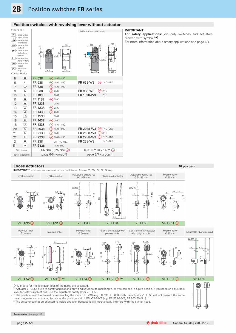
FR 538 1NO+1NC
FR 638 1NO+1NC
FR 738 1NO+1NC
FR 938 2NC
FR 1038 2NO
FR 1138 2NC
FR 1238 2NO
FR 1338 2NC
FR 1438 2NC
FR 1538 2NO
FR 1638 2NC
FR 1838 1NO+1NC
FR 2038 1NO+2NC
FR 2138 3NC
FR 2238 2NO+1NC
FR 238 2x(1NO-1NC)
FR E138 1NO-1NC
FR 638-W3 1NO+1NC
FR 938-W3 2NC
FR 1038-W3 2NO
FR 2038-W3 1NO+2NC
FR 2138-W3 3NC
FR 2238-W3 2NO+1NC
FR 238-W3 2NO+2NC
page 2/51
Min. force
Travel diagrams
Position switches with revolving lever without actuator
General Catalog 2009-2010
Accessories See page 5/1
Position switches FR series
Ø 18 mm roller Ø 18 mm roller Adjustable square rod 3x3x125 mm Flexible rod actuator Adjustable round rod
Ø 3x125 mmPolymer roller
Ø 20 mm
Polymer roller Ø 20 mm Porcelain roller Polymer roller
Ø 20 mmAdjustable actuator with
polymer rollerAdjustable safety actuator
with polymer rollerPolymer roller
Ø 20 mm Adjustable fi ber glass rod
Contacts type:
R = snap actionL = slow action
LO = slow action overlappedLS = slow action
shiftedLV = slow action
shifted and spacedLI = slow action
independent
LA = slow action closer
= electronic PNPContact blocks
0,06 Nm (0,25 Nm )page 6/6 - group 5
0,06 Nm (0,25 Nm )page 6/7 - group 4
with manual reset knob IMPORTANT
For safety applications: join only switches and actuators marked with symbol .For more information about safety applications see page 6/1.
- Only orders for multiple quantities of the packs are accepted.- (1) Actuator VF LE55 suits to safety applications only if adjusted to its max length, as you can see in fi gure beside. If you need an adjustable
lever for safety applications, use the adjustable safety lever VF LE56.- (2) The position switch obtained by assembling the switch FR •38 (e.g. FR 538, FR 638) with the actuator VF LE53 will not present the same
travel diagrams and actuating forces as the position switch FR •53-E0V9 (e.g. FR 553-E0V9, FR 653-E0V9...).- (4) The actuator cannot be oriented to inside direction because it will mechanically interfere with the switch head.
Loose actuators 10 pcs packIMPORTANT: These loose actuators can be used with items of series FR, FM, FX, FZ, FK only
1B
1
1A
2
2A
2B
2C
2D
2E
3
3A
3B
3C
4
4A
4B
4C
4D
4E
4F
4G
4H
5
6
2B
36
209.50.8
7
M4
7
2015
M 4
40
24 720
M 4
10
49
1
7
20
M 4
13.5
40
5
20
7
M 4
10
34 -
93
1 20
7
M 4
10
34 -
93
1
7
20
43
2011
M 4
VF LE31-1 VF LE51-1 VF LE52-1 VF LE54-1 VF LE55-1 (1) VF LE56-1 VF LE57-1
43.5
35
9.5
M4
735
47.5
247
M4
35
56.1
8 9.57
M4
35
47.5
13.57
M4
35
43.5
- 10
1
0.8 9.57
M4
35
41.3
- 10
1.3
0.8 9.57
M4
35
50.5
19.510.87
M4
VF LE31-2 (4) VF LE51-2 (4) VF LE52-2 VF LE54-2 (4) VF LE55-2 (1) VF LE56-2 VF LE57-2
46
40
11.510
M4 M 4
1026
50
40
M 4
1012
40
59
3
M 4
4010
16
50
M 4
4010
1252
.5 -
103.
53
M 4
4010
12
50 -
103.
8
3
M 4
10
22
40
53
VF LE31-R5 (4) VF LE51-R5 (4) VF LE52-R5 VF LE54-R5 (4) VF LE55-R5 (1) VF LE56-R5 VF LE57-R5 (4)
M 4
50
55
10
26
M 4
12
1050
64
5010
M 4
55
16
5010
M 4
58.5
- 10
8
12350 10
M 4
58.8
- 10
8
123
M 4
2250
58
10
VF LE51-3 (4) VF LE52-3 (4) VF LE54-3 (4) VF LE55-3 (1) VF LE56-3 VF LE57-3 (4)
10
50
M 4
20 - 35
58.5
- 10
8
11.4 - 26.4
10
50
M 4
58.8
- 10
8
20 - 3511.4 - 26.4
VF LE55-4 (1) VF LE56-4
page 2/52General Catalog 2009-2010
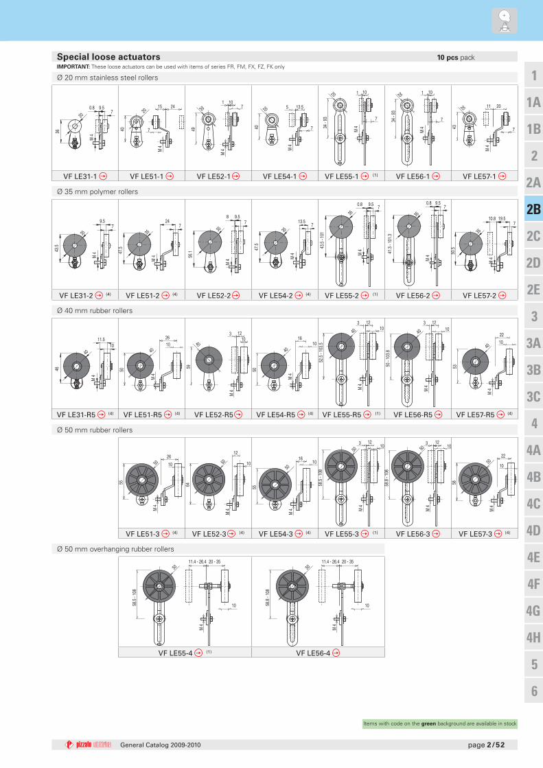
Ø 20 mm stainless steel rollers
Ø 35 mm polymer rollers
Ø 40 mm rubber rollers
Ø 50 mm rubber rollers
Ø 50 mm overhanging rubber rollers
Special loose actuators 10 pcs packIMPORTANT: These loose actuators can be used with items of series FR, FM, FX, FZ, FK only
Items with code on the green background are available in stock


![TME-DC [ ] - Sew Many Parts, Inc. of Contents z TME-DC GENERAL VIEW z TME-DC FRAME … CD-1 z TME-DC TABLE … CD-2-1 z TME-DC AUTO SUB TABLE …](https://static.fdocuments.us/doc/165x107/5b1d28797f8b9add7f8b64eb/tme-dc-sew-many-parts-inc-of-contents-z-tme-dc-general-view-z-tme-dc-frame.jpg)