SIPROTEC 5 Application Note€¦ · · 2016-09-23SIPROTEC 5 Application Communication...
28
www.siemens.com/protection SIPROTEC 5 Application Note SIP5-APN-009: Communication Architecture Under Cyber Security Aspects Answers for infrastructure and cities.
Transcript of SIPROTEC 5 Application Note€¦ · · 2016-09-23SIPROTEC 5 Application Communication...
www.siemens.com/protection
SIPROTEC 5 Application Note SIP5-APN-009: Communication Architecture Under Cyber Security Aspects
Answers for infrastructure and cities.

SIPROTEC 5 Application Communication Architecture Under Cyber Security Aspects
SIP5-APN-009 2
SIPROTEC 5 - Application: SIP5-APN-009 Communication Architecture Under Cyber Security Aspects

SIPROTEC 5 Application Communication Architecture Under Cyber Security Aspects
3 SIP5-APN-009
Content 1 Application Communication Architecture Under Cyber Security Aspects 4 1.1 Summary 4 1.2 System Security Architecture 4 1.3 System Communication 6
1.3.1 System Diagram Examples for SIPROTEC 5 6 1.3.2 Component Recommendation 10 1.3.3 Communication Protocols 12
1.4 System Hardening and Malware Protection 15 1.4.1 SIPROTEC 5 15 1.4.2 DIGSI 5 PC / Remote DIGSI 5 PC 15 1.4.3 Other Substation Control Network Components 18
1.5 SIPROTEC 5 Security Mechanisms 18 1.5.1 Authentication and Encryption Mechanisms 18 1.5.2 Confirmation ID 19 1.5.3 Logging Facilities 20
1.6 Patch and Update Information 21 1.6.1 SIPROTEC 5 21 1.6.2 DIGSI 5 PC / Remote DIGSI 5 PC 21
1.7 Patch and Update Information 22 1.7.1 SIPROTEC 5 22 1.7.2 DIGSI 5 PC / Remote DIGSI 5 PC 22
1.8 Appendix 23 1.8.1 IEC 61850 23 1.8.2 GOOSE 23 1.8.3 DNP3 24 1.8.4 IEC 60870-5-103 protocol 24 1.8.5 Synchro Phasor 24 1.8.6 SNTP 24 1.8.7 SNMP 25 1.8.8 IP Tunneling over PDI 25
1.9 Abbreviations 25 1.10 Reference Documents / Links 26

SIPROTEC 5 Application Communication Architecture Under Cyber Security Aspects
SIP5-APN-009 4
1 Application Communication Architecture Under Cyber Security Aspects
1.1 Summary Many of today’s computer systems—servers, PCs, and automation devices—are highly interconnected. This exposes entire networks to security threats such as hacking, malware, worms, and viruses. In addition, the increased use of common software and operating systems, for example Windows and Linux, and standard communication protocols such as TCP and IP, have also raised vulnerability.
To thwart attacks and ensure system viability, cyber security must be an integral part of the network planning and design process. Planning for security at the outset will provide for a more complete and cost-effective system. Advance planning will also ensure that security features are supportable—attempting to retrofit secure measures into existing environments is often ineffective and cost-prohibitive. Security must be addressed at all levels of the development process.
This Application Note provides guidelines for designing secure automation systems that employ the Siemens SIPROTEC 5 Protection Relays. The guide is intended for use throughout the product life cy¬cle and will be updated whenever major changes are made to the devices.
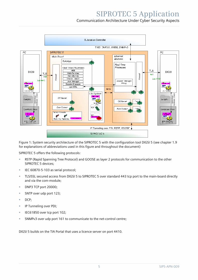
1.2 System Security Architecture SIPROTEC 5 is an embedded device with secure boot mechanisms and cryptographically protected access for configuration and software update. Main security features of the SIPROTEC 5 are:
secure software update with digital signatures
secure configuration via digitally signed configuration items
support of encrypted protocols like HTTPS
authenticated and authorized access with the configuration tool via TLS/SSL connection
role based access to configuration items and device functionality by confirmation IDs
restriction of open ports by DIGSI 5 service configuration
usage of a crypto chip for protected storage of public keys for signature verifications
device individual key material for TLS/SSL communication
The system security architecture is shown in Figure 1. It comprises the following tools and devices:
SIPROTEC 5 with Main Board und Ethernet Module
Configuration tool DIGSI 5 on PC (for customers)
Substation automation system connected via standardized protocols (e.g. SICAM PAS with IEC 61850 protocol)
SIPROTEC 5 Application Communication Architecture Under Cyber Security Aspects
5 SIP5-APN-009
Fire
wal
l
Fire
wal
l
DIG
SI R
oot
Cer
tific
ate
-Che
ck
DIG
SI R
oot
Cer
tific
ate
-Che
ck
Figure 1: System security architecture of the SIPROTEC 5 with the configuration tool DIGSI 5 (see chapter 1.9 for explanations of abbreviations used in this figure and throughout the document)
SIPROTEC 5 offers the following protocols:
RSTP (Rapid Spanning Tree Protocol) and GOOSE as layer 2 protocols for communication to the other SIPROTEC 5 devices;
IEC 60870-5-103 as serial protocol;
TLS/SSL secured access from DIGSI 5 to SIPROTEC 5 over standard 443 tcp port to the main-board directly and via the com-module;
DNP3 TCP port 20000;
SNTP over udp port 123;
DCP;
IP Tunneling over PDI;
IEC61850 over tcp port 102;
SNMPv3 over udp port 161 to communicate to the net-control centre;
DIGSI 5 builds on the TIA Portal that uses a licence server on port 4410.
SIPROTEC 5 Application Communication Architecture Under Cyber Security Aspects
SIP5-APN-009 6
1.3 System Communication
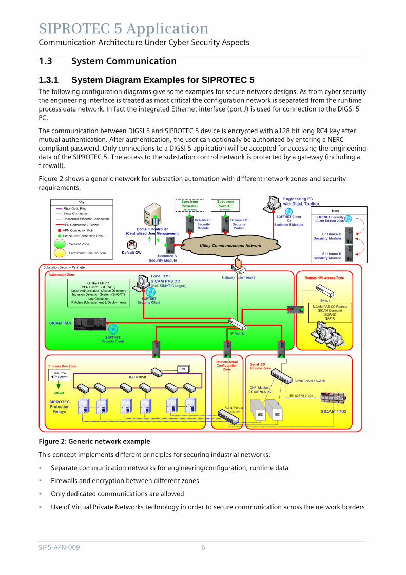
1.3.1 System Diagram Examples for SIPROTEC 5 The following configuration diagrams give some examples for secure network designs. As from cyber security the engineering interface is treated as most critical the configuration network is separated from the runtime process data network. In fact the integrated Ethernet interface (port J) is used for connection to the DIGSI 5 PC.
The communication between DIGSI 5 and SIPROTEC 5 device is encrypted with a128 bit long RC4 key after mutual authentication. After authentication, the user can optionally be authorized by entering a NERC compliant password. Only connections to a DIGSI 5 application will be accepted for accessing the engineering data of the SIPROTEC 5. The access to the substation control network is protected by a gateway (including a firewall).
Figure 2 shows a generic network for substation automation with different network zones and security requirements.
Figure 2: Generic network example
This concept implements different principles for securing industrial networks:
Separate communication networks for engineering/configuration, runtime data
Firewalls and encryption between different zones
Only dedicated communications are allowed
Use of Virtual Private Networks technology in order to secure communication across the network borders

SIPROTEC 5 Application Communication Architecture Under Cyber Security Aspects
7 SIP5-APN-009
1.3.1.1 Electrical Ethernet Star Topology In Figure 3 a simple star topology is shown. The remote and local configuration is done via the on-board Ethernet module via HTTPS.
Figure 3: Star topology with Ethernet modules
1.3.1.2 Electrical / Optical Ethernet Ring Configuration Figure 4 shows a typical ring configuration.
The SIPROTEC 5 relays are connected with two Ethernet modules (electrical/optical) to two switches of the optical ring. This is the so-called dual-homing configuration.
Again local and remote configuration is done via the on-board electrical Ethernet connection over HTTPS.

SIPROTEC 5 Application Communication Architecture Under Cyber Security Aspects
SIP5-APN-009 8
Figure 4: Ring topology of switches with Ethernet Ports – SIPROTEC 5 connected via dual homing mode

SIPROTEC 5 Application Communication Architecture Under Cyber Security Aspects
9 SIP5-APN-009
1.3.1.3 Electrical / Optical Ethernet Ring Configuration with alternative Ring Figure 5 shows a variant of Figure 4 without dual homing and extended loop between SIPROTEC 5 devices.
Figure 5: Ring configuration without dual-homing an extended local loop
Technical notes on system diagram examples
For Figure 4 consider the following: there are optical and electrical SIPROTEC 5 interfaces.
The following rule can be applied for the calculation of the maximum number of SIPROTEC 5 devices in each RSTP ring. An RSTP device should be less than MaxAge hops from the root switch. The maximum number is then:
maximum number = 40 (i.e. max MaxAge) - number of switches in main ring
For all configuration samples, note that the maximum number of 500 network devices is recommended.
The host/device names in the system diagram are used for describing services and protocols in the next chapters.
For more details see /12/.

SIPROTEC 5 Application Communication Architecture Under Cyber Security Aspects
SIP5-APN-009 10
1.3.1.4 Host description
Zone Hosts/Devices Description
Substation Control Network
SIPROTEC 5
SIPROTEC 5 devices
Switches
Optical/electrical Ethernet switches.
Substation Router with optional firewalling functionality
Router device providing network access control to/from substation control network with optional firewalling functionality
Sicam PAS / 1703
Substation control server machines. For details, see SICAM PAS and 1703 blueprints.
DIGSI 5 PC
Permanent DIGSI 5 PC for engineering / maintenance of SIPROTEC 5 devices
Substation Server Network
NTP Server
NTP server providing clock source for time synchronisation
External Networks: Transfer / corporate networks
Remote DIGSI 5 PC
Used for remote service with DIGSI 5, to collect and transfer data from field devices to a remote service engineer
Please note that remote access security is not addressed in the SIPROTEC 5 blueprint. Connectivity for a remote DIGSI 5 system must be protected separately (e.g. through VPN terminating at substation Firewall or remote access router.
Table 1: List of all relevant hosts/devices
1.3.2 Component Recommendation In the following, component recommendations for network devices are given. Certifications have been performed for the recommended devices. Other devices with appropriate electromagnetic compatibility can be used, however, they have not been tested by Siemens and their proper operation can not be guaranteed.

SIPROTEC 5 Application Communication Architecture Under Cyber Security Aspects
11 SIP5-APN-009
1.3.2.1 Substation Router Siemens recommends the utilization of the Ruggedcom RuggedRouter RX1000 appliance (see /4/), which includes fire-walling and other advanced security features.
1.3.2.2 Switches To ensure proper functionality, Siemens requires substation ethernet switches from RuggedCom’s portfolio (see /3/), such as the RS900, RS1600, RS8000 or RSG2100 components for using together with optical SIPROTEC rings (e.g. as in Figure 4).
Alternatively, industrial ethernet switches from Hirschmann (see /5/), such as the RSR20, RSR30 and MACH1000 components are suitable for utilization with SIEMENS components.
Furthermore, SCALANCE switches can be used (see /8/), e.g. the X-300EEC (Enhanced Environmental Conditions) product line that comprises compact Industrial Ethernet switches with IT functions for constructing electrical and/or optical line, star and ring topologies.
If designs are used as described in Figure 4, also other switches of other vendors can be used. In that case, the SIPROTEC 5 devices (with electrical and/or optical Ethernet interface) are connected single or dual armed to the network. The precondition are that only the switches build up one or more rings and all the switches are compliant with IEC61850-3.
1.3.2.3 NTP Server No special requirements for the NTP servers are made, except that the components must have an accuracy of +/- 1 ms. For redundancy purposes, a maximum of 2 NTP servers is possible. Please note that SIPROTEC 5 relies on the widely used standard NTP without cryptographic extensions.
1.3.2.4 Engineering PC (DIGSI PC) From Cyber Security perspective accessing the engineering interface of the protection relays is very critical. Based on this securing the DIGSI PC is essential and includes the following actions:
Using a combination of security software, such as antivirus and antispyware software, personal firewalls, spam and Web content filtering, and popup blocking, to stop most attacks, particularly malware
Restricting who can use the PC by having a separate standard user account for each person, assigning a password to each user account, using the standard user accounts for daily use, and protecting user sessions from unauthorized physical access
Ensuring that updates are regularly applied to the operating system and primary applications, such as Web browsers, email clients, instant messaging clients, and security software
Disabling unneeded networking features on the PC and configuring wireless networking securely
Configuring primary applications to filter content and stop other activity that is likely to be malicious
Installing and using only known and trusted software. It is not recommended to install email clients on a DIGSI PC.
Configuring remote access software based on the organization’s requirements and recommendations
Maintaining the PC’s security on an ongoing basis, such as changing passwords regularly and checking the status of security software periodically.
SIPROTEC 5 Application Communication Architecture Under Cyber Security Aspects
SIP5-APN-009 12
1.3.3 Communication Protocols
1.3.3.1 IP/TCP/UDP/Ethernet Communication Matrix
The overview of the ports and services below supports the administrator to adjust the settings of firewall and intrusion detection systems. Further it is strongly recommended to enable only those services which are used for operation. Any other service has to be disabled.
Service Layer 4 Protocol
Layer 7 Protocol
Typical Client Client Port Typical Server Server Port
DIGSI 5 protocol to Automation License Manager
TCP DIGSI 5 protocol to Automation License Manager
DIGSI 5 PC 4410
(default value)
Automation License Manager on a possible separate server,
i.e. local host
4410
(default value)
DIGSI 5 communication protocol to SIPROTEC 5
TCP HTTPS DIGSI 5 PC >1024 SIPROTEC 5 443
Reporting / IEC 61850 / MMS
TCP IEC61850 IEC 61850 client (e.g. SICAM PAS, SICAM 1703)
>1024 SIPROTEC 5 102
Time Synchroni-zation / SNTP
UDP SNTP SIPROTEC 5 123 SNTP Server 123
Monitoring via Simple Network Management Protocol (SNMPv3)
UDP SNMPv3 PC with SNMP client (e.g. SICAM PAS / 1703 / DIGSI 5 PC / Remote DIGSI 5 PC)
>1024 SIPROTEC 5 161
DNP3i TCP DNP3 TCP SICAM PAS 20000 or next free port
SIPROTEC 5 20000
Synchrophasor
TCP
UDP
Phasor data concentrator
>1024 SIPROTEC 5 4712
4713
MODBUS on TCP
(not yet provided)
TCP MODBUS Substation controller
>1024 SIPROTEC 5 502
Temperature box
UDP RTD Temperature box
>1024 SIPROTEC 5 can be configured

SIPROTEC 5 Application Communication Architecture Under Cyber Security Aspects
13 SIP5-APN-009
Service Layer 4 Protocol
Layer 7 Protocol
Typical Client Client Port Typical Server Server Port
(not yet provided)
Table 2: List of communication matrix
1.3.3.2 Communication Interfaces The following protocols are available depending on the configuration of the SIPROTEC 5 device as well as on the operation status of the device. Services that are not required e.g. like the redundancy protocol RSTP can be turned off within DIGSI 5. In this case the disabled interfaces will not be offered to the network.
Protocol Ethernet module (optical and electrical)
Integrated Ethernet interface (Port J) on the main board
USB interface on the front panel
DCP x X
DHCP x X
DNP 3 TCP x
IEC 61850 - GOOSE x
IEC 61850 Reporting / MMS x X
RSTP x
SNMPv3 x
SNTP x X
SSL/TLS x X x
IP Tunneling over PDI x
Synchrophasor x X
MODBUS x X
Temperature box x X
Figure 6 shows how services of the SIPROTEC 5 device can be enabled or disabled using DIGSI 5. For more detailed information please refer to the SIPROTEC 5 Operating Manual.

SIPROTEC 5 Application Communication Architecture Under Cyber Security Aspects
SIP5-APN-009 14
Figure 6: Service Dialog of DIGSI

SIPROTEC 5 Application Communication Architecture Under Cyber Security Aspects
15 SIP5-APN-009
1.4 System Hardening and Malware Protection With respect to the malware protection it has to be differentiated between the SIPROTEC 5 device itself, the DIGSI 5 configuration PC and the attached components. As the involved components have different operating systems and different network protection mechanism, malware defense has to be handled differently.
1.4.1 SIPROTEC 5 The SIPROTEC 5 device is based on the VxWorks operating system. So far, VxWorks is not a dedicated target of malware. Therefore, there are no anti-virus tools available. In addition, the SIPROTEC 5 device is equipped with an internal firewall to be protected against network attacks. This firewall is turned on by default to increase the standard protection.
All files that can be uploaded to the SIPROTEC 5 device are digitally signed to protect against modification by malware. Because of the authentication/authorization between DIGSI 5 and the device no other application except DIGSI 5 can make an engineering access.
Furthermore, the classic ways for infection are via e-mail or browsing in the internet. SIPROTEC 5 does not offer e-mail or browser applications and is therefore not susceptible to those infection ways.
1.4.2 DIGSI 5 PC / Remote DIGSI 5 PC
1.4.2.1 Malware Protection General
The DIGSI 5 PC and the remote DIGSI 5 PC are based on Windows operating systems. Therefore, in order to protect against malware infection, it is recommended to install an anti-virus tool with permanent updated anti-virus patterns. Recommended anti-virus tool is:
Trend Micro OfficeScan
In order to prevent infection via USB devices like USB sticks or USB hard disks, the "autostart" function should be deactivated. This helps preventing automatic execution of malware. In addition it is recommended to scan all USB devices on malware with an updated anti-virus tool before attaching it to the DIGSI 5 PCs. The anti-virus tool must be configured “on-access” operation mode. The same applies for CD or DVD media.
Aside the infection via USB devices, malware can spread via e-mails or websites. Therefore, it is recommended to install a mail anti-virus tool and a content filter to avoid browsing on unsecure web pages.
The DIGSI 5 PC has to be configured in a secure way to avoid infection with malware (see chapter 1.4.2.2). A secure configuration comprises also the continuous patching of all installed 3rd party components.
System administrators have to be educated to use their administration systems (DC, file server, etc.) for no other than administrative purposes. In particular, DIGSI 5 systems used to administer must not be used to:
Surf the Internet or playback any multimedia contents.
Test/install untrustworthy software from dubious sources (Internet / shareware CDROM).
Experiment with the DIGSI 5 PC
If the DIGSI PC is a completely isolated PC without network connection, an update of the virus scanner might not be possible. In this case it has to be assured by technical and organisational means that no malware can be put on the PC e.g. by forbidding the use of USB sticks.

SIPROTEC 5 Application Communication Architecture Under Cyber Security Aspects
SIP5-APN-009 16
Virus scanner system
Virus scanners are available in different flavours, as standalone products or for commercial environments as client-/server-application. Below a sample configuration environment is shown. Via a virus scan server the setup packages, configuration and updated pattern will be deployed. The mechanisms are “push” or “pull” to get the information or software to the systems.
Setup+
Config
uratio
n_1
Set
up+C
onfig
urat
ion_
2 Setup+Configuration_nPush o
r Pull
Push or Pull
Push
or P
ull
1.4.2.2 Measures to hardening your system A description which services are used (ports and protocols, see chapter 1.3.3.1) on the system must be
available and the firewall must be configured accordingly.
Deactivate all unnecessary services. A typically used service is the “File and Printer sharing for Microsoft networks”. If you do not use shared folders on your system deactivate this service.
Create a special windows user group for your installed application. Only this group is allowed to start the specified application and browse to these folders.
Create users which are members of the Windows user group and your defined program group. NEVER use an administrator account for regular usage. Only these defined users are allowed to use the installed applications. This measurement grants a high level of security to avoid the infiltration of harmful DLL- or EXE-files.
Install security patches of the installed products manually after testing it by yourself or the Windows patch is released by Siemens.
Install the recommended virus scanner on your system with the option “on access” to avoid spreading malware via storage devices (CD, USB stick …) or file sharing. Please note that only daily updated virus patterns/signatures grant a high level of security.
If plain text protocols are used to communicate with other communication partners use the Windows integrated IPSec solution (also integrated in numerous Unix systems, e.g. strongSwan) to secure and authenticate the connection. Note: Also a mix between a Windows and UNIX system will work fine. If you
SIPROTEC 5 Application Communication Architecture Under Cyber Security Aspects
17 SIP5-APN-009
are using firewalls open the IPSec ports on your firewall (ESP / UDP port 500 or UDP port 4500 / UDP port 500)
It is recommended to establish a domain controller concept with proper password rules as a local policy based user group set.
The 10 major configuration faults
Never use the Windows “Guest” account. Deactivate this account!
Never allow “everyone” access to your shared folder. Delete this access right group and add the right user group. Set the read/write access rights within the “Security” tab.
Never use a user account as a member of administrator group for regular use.
Never use simple user account passwords – take minimum eight alpha numeric characters together with special characters.
If practicable change your passwords periodical.
Never run Windows without activated Windows Firewall unless you are running your system exclusively in a trusted security perimeter zone.
Never run an unpatched Windows unless you are running your system exclusively in a trusted security perimeter zone.
Never run windows without an up-to-date virus scanner unless you are running your system exclusively in a trusted security perimeter zone.
If practicable don’t use 3rd party software with known security vulnerabilities. If necessary build a trusted security perimeter zone
Never install untrusted software on your productive system.
Desktop Firewalling
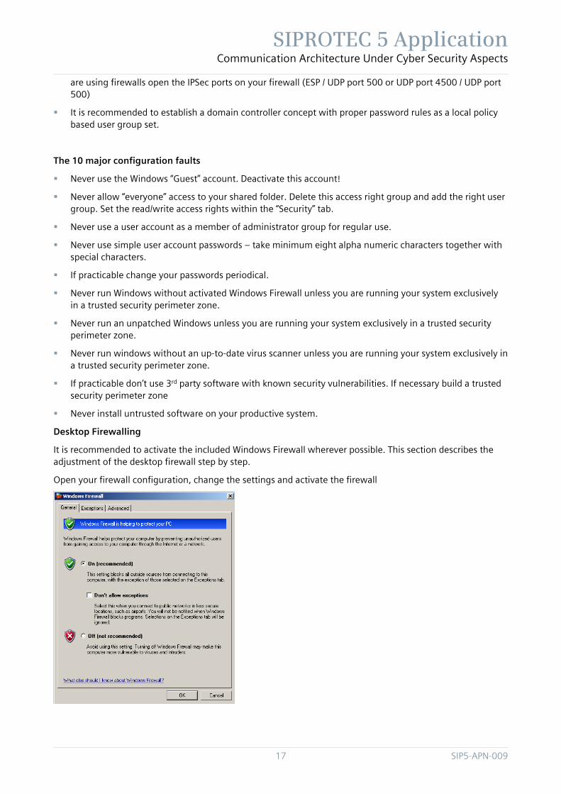
It is recommended to activate the included Windows Firewall wherever possible. This section describes the adjustment of the desktop firewall step by step.
Open your firewall configuration, change the settings and activate the firewall

SIPROTEC 5 Application Communication Architecture Under Cyber Security Aspects
SIP5-APN-009 18
The DIGSI 5 application itself needs no special open port because there are no incoming connections.
Beside the “network core” service you need also the exception for File and Printer Sharing (Port 139 / 445) if you use shared network folders, Network Discovery and the Remote Event Log Management if you need Remote Log Events. Disable File and Printer Sharing if no shared folders used on your DIGSI 5 PC.
1.4.3 Other Substation Control Network Components The Substation Control Network comprises further components like SICAM PAS, TM1703 substation controllers or NTP server. For a secure operation of the Substation Control Network it has to be assured that all these components are configured and operated to the security standards NERC CIP /1/ and BDEW White Paper /2/.
The substation control protocols (e.g. IEC 61850) are not secured. Therefore it's strictly recommended to connect this network not directly to an unsecured network. Connection to an unsecured network must be done via a router with an included firewall.
1.5 SIPROTEC 5 Security Mechanisms For operation of the SIPROTEC 5 a number of comprehensive security mechanisms are available to protect the device from unintended operations or adverse attacks. Detailed information about the SIPROTEC 5 security mechanisms is available in the SIPROTEC 5 operating manual /6/.
1.5.1 Authentication and Encryption Mechanisms Before DIGSI 5 can communicate with the SIPROTEC 5 device, an authentication by the device is performed. In addition, a specific connection password can be configured, which has to be provided by the DIGSI 5 client to the SIPROTEC 5 device. This connection password can be configured to cope with the security requirements of NERC CIP-007-4 /1/. NERC CIP-007-4 R5.3 specifies the following password policy:
Each password shall be a minimum of six characters.

SIPROTEC 5 Application Communication Architecture Under Cyber Security Aspects
19 SIP5-APN-009
Each password shall consist of a combination of alpha, numeric, and “special” characters.
Each password can be changed based on risk.
Extending the NERC CIP requirements the connection password must be a minimum of eight characters and can have a length of 24 characters.
After correct authentication, read access is allowed to the device functions.
The whole communication with the SIPROTEC 5 device is performed via an encrypted HTTPS connection. Therefore, configuration commands and details are protected against eavesdropping by attackers.
Figure 7: DIGSI view for activating the connection PWD
Figure 8: DIGSI view when connectionPWD is not compliant to NERC/CIP
1.5.2 Confirmation ID For write access to the device functions a kind of role based access to the SIPROTEC 5 device is implemented. There are different roles predefined for the particular tasks, e.g. a Switching User. For identifying each role a confirmation ID can be assigned in order to protect safety relevant device operations. Particular roles can be activated or deactivated according to the requirements of the operational environment (refer to Figure 9).

SIPROTEC 5 Application Communication Architecture Under Cyber Security Aspects
SIP5-APN-009 20
Figure 9: DIGSI 5 role administration menu
1.5.3 Logging Facilities Wrong passwords are detected and logged. An appropriate alarming via remote connection can be configured. Furthermore security-relevant operations like failed logins, change of password etc. are logged and can not be deleted within the device. It can be read out by DIGSI 5. In addition the logging information can be transmitted to a substation automation system.
The security log inside SIPROTEC 5 can be not deleted by the user.
Figure 10: Cyber security message transferable to the net control centre; for explanation see

SIPROTEC 5 Application Communication Architecture Under Cyber Security Aspects
21 SIP5-APN-009
Mode Name Explanation
Cyber security state
Logon blocked Logon with connection PWD blocked due to 3 wrong entries; blocking lasts for 5 minutes
Logon reactivated Logon reactivated; 5 minutes passed after three wrong entries
Cyber security event
PW change OK Connection password could be changed successfully in SIPROTEC 5
PW change not OK Connection password could not be changed successfully in SIPROTEC 5
Logon OK Successful Logon with connection password
Logon not OK Logon with connection password failed
PW activation OK Successful activation of the connection password
PW activation not OK Activation of connection failed
PW deactivation OK Successful deactivation of the connection password
PW deactivation n. OK Deactivation of the connection password failed
Table 3: Log events transferable to the net control centre with description
1.6 Patch and Update Information Information security plays an important role in the complete product life cycle. Patch management for software is an essential part of this process.
In the special environment it has to be differentiated between the SIPROTEC 5 device itself and the DIGSI 5 PC. As the involved components have different operating systems and different network protection mechanism, patch and update mechanism has to be handled differently.
1.6.1 SIPROTEC 5 A special attention has been paid for the patch and update process of the SIPROTEC 5 devices.
The complete software for SIPROTEC 5 is protected by digital signatures in order to detect malicious changes. Only such officially signed software components can be loaded and are executed on the device. The customer can obtain SIPROTEC 5 software, patches and updates from the official SIPROTEC 5 Web site of Siemens Energy Automation /7/. The customer will be informed if critical software patches are available.
The import of the software into the SIPROTEC 5 device is done by using DIGSI 5. During the import of the software updates by DIGSI 5, signature verification is performed in the device loader. The software components of the Com modules can also be loaded via the main board.
Further information about the upgrade process is described in /6/.
1.6.2 DIGSI 5 PC / Remote DIGSI 5 PC Usually security updates of third-party products have no impact on the DIGSI 5 application. To be really sure, contact Siemens to get information about Windows patch compatibility to DIGSI 5.
It is recommended to test a security update of a third-party product in a test environment prior to an installation on a productive DIGSI 5 PC.

SIPROTEC 5 Application Communication Architecture Under Cyber Security Aspects
SIP5-APN-009 22
Because of that make sure the automated update process of the installed products, e.g. Microsoft Windows or Adobe Acrobat is deactivated on your DIGSI 5 PC.
Install security patches of the installed products manually after testing it by yourself or the Windows patch is released by Siemens.
Furthermore you can build your own WSUS (Windows Server Update Services) server. With WSUS you can distribute all Microsoft patches to your installed windows systems after testing it in your test environment or after release of Siemens. The mechanism is similar to the Client-Server Virus scan construct. All system gets their patches via the build-in windows automated update mechanism. The significant difference is the server which provides the patches.
Unfortunately not all software suppliers provide such a remote update system as Microsoft. If you have no direct or proxy-server internet access you have to provide your system manually with the necessary patches. Have a look on the manufacture homepage periodically.
1.7 Patch and Update Information Information security plays an important role in the complete product life cycle. Patch management for software is an essential part of this process.
In the special environment it has to be differentiated between the SIPROTEC 5 device itself and the DIGSI 5 PC. As the involved components have different operating systems and different network protection mechanism, patch and update mechanism has to be handled differently.
1.7.1 SIPROTEC 5 A special attention has been paid for the patch and update process of the SIPROTEC 5 devices.
The complete software for SIPROTEC 5 is protected by digital signatures in order to detect malicious changes. Only such officially signed software components can be loaded and are executed on the device. The customer can obtain SIPROTEC 5 software, patches and updates from the official SIPROTEC 5 Web site of Siemens Energy Automation /7/. The customer will be informed if critical software patches are available.
The import of the software into the SIPROTEC 5 device is done by using DIGSI 5. During the import of the software updates by DIGSI 5, signature verification is performed in the device loader. The software components of the Com modules can also be loaded via the main board.
Further information about the upgrade process is described in /6/.
1.7.2 DIGSI 5 PC / Remote DIGSI 5 PC Usually security updates of third-party products have no impact on the DIGSI 5 application. To be really sure, contact Siemens to get information about Windows patch compatibility to DIGSI 5.
It is recommended to test a security update of a third-party product in a test environment prior to an installation on a productive DIGSI 5 PC.
Because of that make sure the automated update process of the installed products, e.g. Microsoft Windows or Adobe Acrobat is deactivated on your DIGSI 5 PC.
Install security patches of the installed products manually after testing it by yourself or the Windows patch is released by Siemens.
Furthermore you can build your own WSUS (Windows Server Update Services) server. With WSUS you can distribute all Microsoft patches to your installed windows systems after testing it in your test environment or after release of Siemens. The mechanism is similar to the Client-Server Virus scan construct. All system gets their patches via the build-in windows automated update mechanism. The significant difference is the server which provides the patches.
SIPROTEC 5 Application Communication Architecture Under Cyber Security Aspects
23 SIP5-APN-009
Unfortunately not all software suppliers provide such a remote update system as Microsoft. If you have no direct or proxy-server internet access you have to provide your system manually with the necessary patches. Have a look on the manufacture homepage periodically.
1.8 Appendix
1.8.1 IEC 61850 Change of relay parameters is possible via IEC 61850 protocol. This is a security relevant feature which shall be done only via secured networks.
IEC 61850 MMS is an unsecured protocol.
IEC 61850 client server communication and GOOSE – telegrams can be sent on different Ethernet modules. Also DIGSI can use a separate Ethernet port which allows to separate substation protocol communication from engineering access with DIGSI 5.
For more details see /12/.
Note: Communication between DIGSI 5 and SIPROTEC 5 is secured with SSL encryption.
1.8.2 GOOSE With IEC61850 there is the possibility to reduce or substitute the classical hard wired connections between field devices with a direct communication via the Ethernet station bus. The used protocol for that purpose is the so-called "GOOSE"-protocol (Generic Object Orientated Substation Event). Information, which shall be transmitted, will be grouped in so-called datasets, depending on the application. This information will be send out of the source by a telegram. The protocol works at L2-base with MAC-addresses, a typical L3/L4-structure doesn’t exist; therefore the protocol cannot leave the subnet via a routing instance. (Some routers still offer the possibility of "GOOSE"-tunneling for substation-to-substation-communication, with that feature you can "route" dedicated GOOSE telegrams from one subnet to another).
The destination MAC-address of the GOOSE telegram is always a virtual multicast MAC-address out of a reserved range in the IEC61850. Therefore every GOOSE-telegram (typical size 200 Byte) will be broadcasted to every port (and MAC-address) of the (Sub-) network. All field devices will receive these telegrams and will check with their internal IEC61850 settings, if the device is a subscriber of the GOOSE-message.
GOOSE-telegrams are always "one-way"-telegrams. A receiving device will never send back an acknowledgement to the sending device or any other response with a direct related reference to the received message.
GOOSE-messages will be send out cyclic, if there is no state change in any of the information, the typical repetition time is in the range of one or even more seconds. In case of a state change a spontaneous GOOSE-message with the new state(s) will be send out immediately, independent of the interval of the cyclic GOOSE-message. Afterwards GOOSE-messages will be send out in very short intervals of just a few milliseconds, respectively with doubled time intervals till the cyclic interval is obtained.

SIPROTEC 5 Application Communication Architecture Under Cyber Security Aspects
SIP5-APN-009 24
Figure 11: Schematic view of GOOSE messages
1.8.3 DNP3 DNP3 is offered in two variants:
Ethernet based; and
Serial.
1.8.4 IEC 60870-5-103 protocol The IEC 60870-5-103 protocol, also called T103, is a serial protocol.
1.8.5 Synchro Phasor Ethernet-based version is used. SIPROTEC 5 is the server, i.e. receiving connection from phasor data concentrator (PDC). PDC requests then phasor data from SIPROTEC 5.
The following standard ports according to /10/ are used on SIPROTEC 5:
Port 4712 for TCP;
Port 4713 for UDP.
1.8.6 SNTP SNTPv4 according to /11/ is used over standard port 123.
IP-address of the timing server is set via DIGSI.
SIPROTEC 5 sends the timing requests to the configured IP-address and compares the IP-address of the received telegrams with the configured one. Answers are discarded if the senders’ IP-address is not the configured one.

SIPROTEC 5 Application Communication Architecture Under Cyber Security Aspects
25 SIP5-APN-009
1.8.7 SNMP SNMPV3 is used with the User Security Model. The deployment is as described in /9/.
1.8.8 IP Tunneling over PDI The user can use a PC to access other devices within the constellation via the protection links. DIGSI 5 communication then operates exclusively via the connections and the protection-data communication is turned off. In this way, the user operates the remote devices from the local device via DIGSI 5.
For more details see the SIPROTEC 5 device manual /13/.
1.9 Abbreviations List of document specific abbreviations:
Table 4: Abbreviations
Term Explanation
DCP Discovery and Configuration Protocol, from Siemens Industry
DHCP Dynamic Host Configuration Protocol
DNP3 TCP DNP3 over Ethernet
RSTP Rapid Spanning Tree protocol
SSL Secure socket layer
TLS Transport layer security; used from SSL v3.1 and above
NFS Network File System
LCS Automation License Server
PDI Protection Interface

SIPROTEC 5 Application Communication Architecture Under Cyber Security Aspects
SIP5-APN-009 26
1.10 Reference Documents / Links /1/ North American Electric Reliability Council:
Critical Infrastructure Protection (CIP), CIP-001-1 through CIP-009-4, 24-01-2011 http://www.nerc.com/
/2/ Bundesverband der Energie- und Wasserwirtschaft: White Paper Requirements for Secure Control and Telecommunication Systems, Berlin, June 2008 http://www.bdew.de/bdew.nsf/id/A975B8333599F9B0C12574B400348E7A/$file/Whitepaper_Secure_Systems_Vedis_1.0final.pdf
/3/ RuggedCom Inc. Ethernet Switch Product Portfolio http://www.ruggedcom.com/products/ruggedswitch/
/4/ RuggedCom Inc. RuggedRouter RX1000 Cyber Security Appliance http://www.ruggedcom.com/products/ruggedrouters/rx1000/
/5/ Hirschmann Hirschmann Industrial Ethernet Switches Product Portfolio http://www.hirschmann-ac.de/English/industrial-ethernet-products/product-overview/index.phtml
/6/ SIPROTEC 5 Website of Siemens Energy Automation: Operating Manual http://www.siprotec.com
/7/ SIPROTEC 5 Website of Siemens Energy Automation: http://www.siprotec.com
/8/ Siemens Scalance switch: http://www.automation.siemens.com/mcms/industrial-communication/de/ie/IE_switches_medienkonverter/scalance-x-300-managed/Seiten/scalance-x-300-managed.aspx
/9/ User-based Security Model (USM) for version 3 of the Simple Network Management Protocol (SNMPv3), http://tools.ietf.org/html/rfc3414
/10/ IEEE Standard for Synchrophasors for Power Systems: IEEE_C37.118_2005, http://www.techstreet.com/cgi-bin/detail?doc_no=IEEE%7CC37_118_2005&product_id=1265953
/11/ Simple Network Time Protocol (SNTP) Version 4 for IPv4, IPv6 and OSI: RFC 4340, http://www.rfc-archive.org/getrfc.php?rfc=4330
/12/ SIPROTEC 5 Website of Siemens Energy Automation: IEC61850 Manual http://www.siprotec.com
/13/ SIPROTEC 5 Website of Siemens Energy Automation: Device Manual http://www.siprotec.com

SIPROTEC 5 Application Communication Architecture Under Cyber Security Aspects
27 SIP5-APN-009

SIPROTEC 5 Application Fehler! Verweisquelle konnte nicht gefunden werden.
SIP5-APN-009 28
Published by and copyright © 2013:
Siemens AG
Infrastructure & Cities Sector
Smart Grid Division
Humboldtstr. 59
90459 Nuremberg, Germany
Siemens AG
Infrastructure & Cities Sector
Smart Grid Division
Energy Automation
Humboldtstr. 59
90459 Nuremberg, Germany
www.siemens.com/protection
Printed on elementary chlorine-free bleached paper.
All rights reserved.
If not stated otherwise on the individual pages of this catalog, we reserve
the right to include modifications, especially regarding the stated values,
dimensions and weights. Drawings are not binding.
All product designations used are trademarks or product names of Siemens
AG or other suppliers.
If not stated otherwise, all dimensions in this catalog are given in mm.
Subject to change without prior notice.
The information in this document contains general descriptions of the
technical options available, which may not apply in all cases. The required
technical options should therefore be specified in the contract.
For more information, please contact our Customer Support Center. Tel.: +49 180 524 8437 Fax: +49 180 524 24 71 (Charges depending on provider) E-mail: [email protected]
Application note: SIP5-APN-009


![Digsi Manual XML a2 en[1]](https://static.fdocuments.us/doc/165x107/54fe3eab4a7959055e8b4d59/digsi-manual-xml-a2-en1.jpg)