
Single Phase Meter Components - uploads.westernenergy.org · 8/3/2018 3...
39
8/3/2018 1 EXCHANGING EXPERTISE SINCE 1893 NWEMS Single Phase Meter Components August 21, 2017| Track A | Scott Sutton, Snohomish County PUD EXCHANGING EXPERTISE SINCE 1893 PURPOSE of this class: » What is an electro‐mechanical Watt‐hour meter » The basic parts of the meter – The function of these parts » Adjustments for calibrations » Compensations » Electronic vs Electromechanical meters » Meter types – Examples – Q & A
Transcript of Single Phase Meter Components - uploads.westernenergy.org · 8/3/2018 3...
8/3/2018
1
EXCHANGING EXPERTISE SINCE 1893
NWEMS
Single Phase Meter ComponentsAugust 21, 2017| Track A | Scott Sutton, Snohomish County PUD
EXCHANGING EXPERTISE SINCE 1893
PURPOSE of this class:
» What is an electro‐mechanical Watt‐hour meter
» The basic parts of the meter
– The function of these parts
» Adjustments for calibrations
» Compensations
» Electronic vs Electromechanical meters
» Meter types – Examples – Q & A
8/3/2018
2
EXCHANGING EXPERTISE SINCE 1893
The Watt‐hour meter
» Measures energy used ‐
» Power is a rate at which energy flows
– Power X Time = Energy
EXCHANGING EXPERTISE SINCE 1893
Relate the Watt‐hour meter to the speedometer and odometer of an automobile
–Miles per hour = Watts being used ‐
Disk speed
–Miles driven = Kilowatt hours –
Register Read
» 30 MPH for 2 hours = 60 miles driven
» 30 kW for 2 hours = 60 kWh
8/3/2018
3
EXCHANGING EXPERTISE SINCE 1893
Today’s Electromechanical kWh meter’s are basically the same design as the ones manufactured 105 years ago.
» Much less expensive
» Light weight
» Highly accurate
» Maintenance free device
» Provide many years of reliable service
EXCHANGING EXPERTISE SINCE 1893
Today's meters are vastly improved:
» They are highly accurate and have a very flat
accuracy curve over extreme loads and
environmental conditions. Single phase self
contained meter’s are so well calibrated from the
manufacture that many utilities do not test new
meters . They may perform a BAR‐X,(sigma) or
Sample Test
8/3/2018
4
EXCHANGING EXPERTISE SINCE 1893
Basic Parts:
» Name Plate
» Base
» Cover
» Frame & magnets
» Stator ‐ potential coil and current coil
» Rotor(disk) and bearings
» Register
EXCHANGING EXPERTISE SINCE 1893
Basic Parts: Nameplate
» The most important part of meter
» Form Number ‐ Indicates the internal connections of
the meter. ANSI Stds.
» Voltage ‐ Design or test voltage of potential coil
» CL or Class ‐ Maximum current capacity.
– CL10, CL20, CL100, CL200, CL320‐

8/3/2018
5
EXCHANGING EXPERTISE SINCE 1893
Basic Parts: Nameplate (continued)
» T.A. ‐ Test Amps, (100% Full Load – 10% Light Load)
» Wire ‐ (2w, 3w, 4w, 5w)
» Kh ‐ Watt‐hour Constant
» Multiplier (CT’s, VT’s, internal meter multi)
» Number of stators or potential coils
» Company ID number and MFR. Type
EXCHANGING EXPERTISE SINCE 1893 10
Meter Nameplates
Service Application Manufacture
Frequency HZ
Voltage
# of Stators Class
Company Name and Number
Manufacturer’s Serial #
Register Ratio
Manufacturer Type
Form
Wires
Test Amps
Disk Constant or Kh

8/3/2018
6
EXCHANGING EXPERTISE SINCE 1893
Basic Parts: Base
» Earlier meter bases were made of cast iron, metal alloys and cast aluminum
» Today’s bases are made of high impact strength plastic
» Base configurations ‐ Socket type, A base type & Bolt In type (K base)
EXCHANGING EXPERTISE SINCE 1893
Basic Parts: Base (continued)
» Test Link ‐ used to disconnect or isolate one side of the potential circuit from the current circuit when testing
» Screened vents ‐ To prevent insects and dust from getting into meter and allows ventilation to minimize condensation

8/3/2018
7
EXCHANGING EXPERTISE SINCE 1893
Basic Parts:Base (continued)
» Lightening Arrestor ‐ To protect meter from High
Surge Currents
– an air gap between the current coil and ground that will “Flash Over” between 5000 & 6500 volts
» Gasket ‐ Provides a seal between the base & cover
» Hanger ‐ Storage
» Sealing Provision ‐ Security
EXCHANGING EXPERTISE SINCE 1893
Basic Parts: Cover
» Purpose ‐ To protect the meter components from weather and dust while providing a means to read the register and inspect meter
» Security ‐ Makes it difficult to tamper with or to conceal tampering
8/3/2018
8
EXCHANGING EXPERTISE SINCE 1893
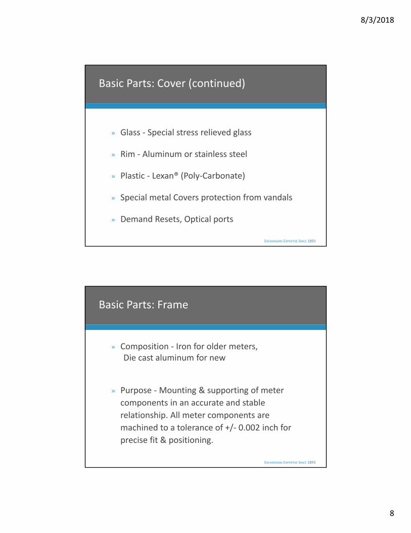
Basic Parts: Cover (continued)
» Glass ‐ Special stress relieved glass
» Rim ‐ Aluminum or stainless steel
» Plastic ‐ Lexan® (Poly‐Carbonate)
» Special metal Covers protection from vandals
» Demand Resets, Optical ports
EXCHANGING EXPERTISE SINCE 1893
Basic Parts: Frame
» Composition ‐ Iron for older meters, Die cast aluminum for new
» Purpose ‐ Mounting & supporting of meter
components in an accurate and stable
relationship. All meter components are
machined to a tolerance of +/‐ 0.002 inch for
precise fit & positioning.
8/3/2018
9
EXCHANGING EXPERTISE SINCE 1893
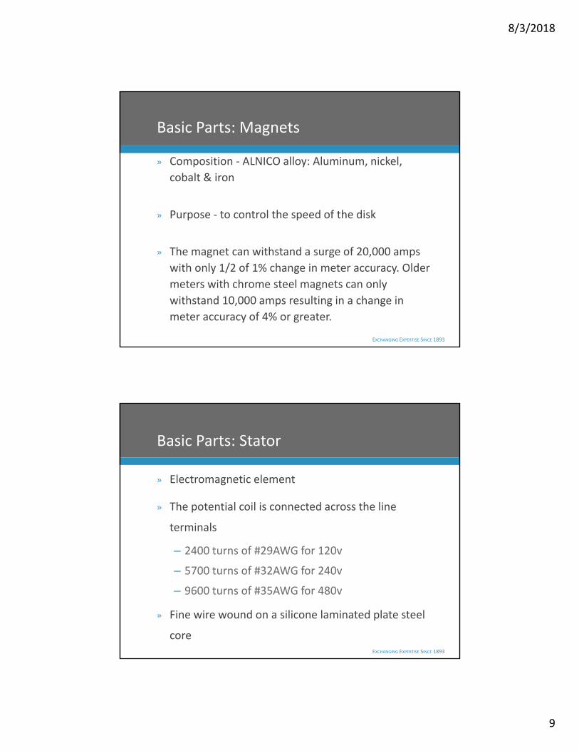
Basic Parts: Magnets
» Composition ‐ ALNICO alloy: Aluminum, nickel,
cobalt & iron
» Purpose ‐ to control the speed of the disk
» The magnet can withstand a surge of 20,000 amps
with only 1/2 of 1% change in meter accuracy. Older
meters with chrome steel magnets can only
withstand 10,000 amps resulting in a change in
meter accuracy of 4% or greater.
EXCHANGING EXPERTISE SINCE 1893
Basic Parts: Stator
» Electromagnetic element
» The potential coil is connected across the line
terminals
– 2400 turns of #29AWG for 120v
– 5700 turns of #32AWG for 240v
– 9600 turns of #35AWG for 480v
» Fine wire wound on a silicone laminated plate steel
core
8/3/2018
10
EXCHANGING EXPERTISE SINCE 1893
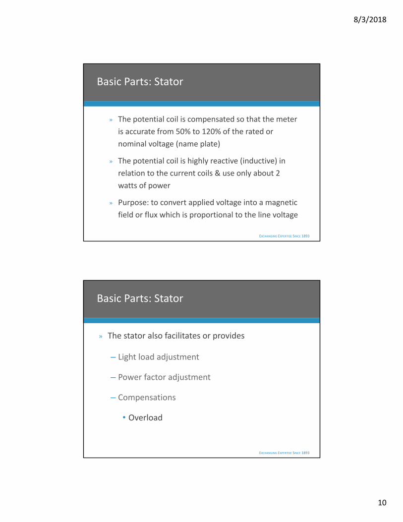
Basic Parts: Stator
» The potential coil is compensated so that the meter
is accurate from 50% to 120% of the rated or
nominal voltage (name plate)
» The potential coil is highly reactive (inductive) in
relation to the current coils & use only about 2
watts of power
» Purpose: to convert applied voltage into a magnetic
field or flux which is proportional to the line voltage
EXCHANGING EXPERTISE SINCE 1893
Basic Parts: Stator
» The stator also facilitates or provides
– Light load adjustment
– Power factor adjustment
– Compensations
• Overload
8/3/2018
11
EXCHANGING EXPERTISE SINCE 1893
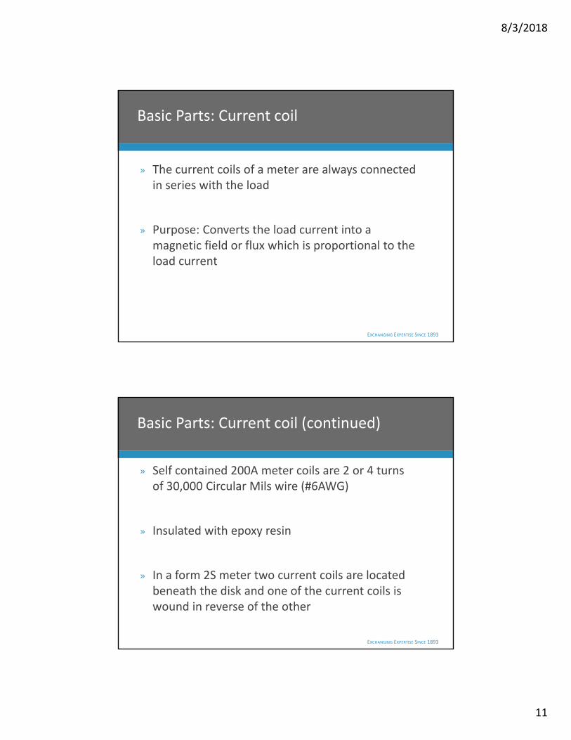
Basic Parts: Current coil
» The current coils of a meter are always connected in series with the load
» Purpose: Converts the load current into a magnetic field or flux which is proportional to the load current
EXCHANGING EXPERTISE SINCE 1893
Basic Parts: Current coil (continued)
» Self contained 200A meter coils are 2 or 4 turns of 30,000 Circular Mils wire (#6AWG)
» Insulated with epoxy resin
» In a form 2S meter two current coils are located beneath the disk and one of the current coils is wound in reverse of the other

8/3/2018
12
EXCHANGING EXPERTISE SINCE 1893
Basic Parts: Rotor or Disk
» Two parts ‐ Disk and the shaft
» Composition ‐ Pure aluminum
– Good conductivity
– Light weight
» Disk is stippled for mechanical strength or stiffness
EXCHANGING EXPERTISE SINCE 1893
Basic Parts: Rotor or Disk (continued)
» Graduations painted on the disk for testing
» Edge is serrated for testing at the factory
» Two holes in disk are called Anti‐Creep holes
– these prevent disk rotation when only potential is applied ‐ no load current
» On the shaft a worm gear is cut

8/3/2018
13
EXCHANGING EXPERTISE SINCE 1893
Basic Parts: Bearings
» Two types of bearings ‐ Mechanical and
Magnetic
» Mechanical Bearings – no longer used
– Pivot type: Hardened tip which rides on a sapphire cup
– Ball type: Ball bearing rides between two sapphire cups
EXCHANGING EXPERTISE SINCE 1893
Basic Parts: Bearings (continued)
» Magnetic Bearings
–Mutual attraction at top of disk shaft or
– Repulsion at bottom of disk shaft
– Vertical alignment by stainless steel guide pins in the magnets to the top and bottom of the disk shaft
» Mechanical bearing required much more maintenance than magnetic bearings

8/3/2018
14
EXCHANGING EXPERTISE SINCE 1893
Break Time
» 10 minutes
EXCHANGING EXPERTISE SINCE 1893
Basic Parts: Register
» A system of gears, dials and pointers designed to count or accumulate the number revolutions of the disk
» The disk rotates at a design speed proportional to the load watts
» Each revolution represents a definite number of watts delivered to the load during the time required for that revolution
8/3/2018
15
EXCHANGING EXPERTISE SINCE 1893
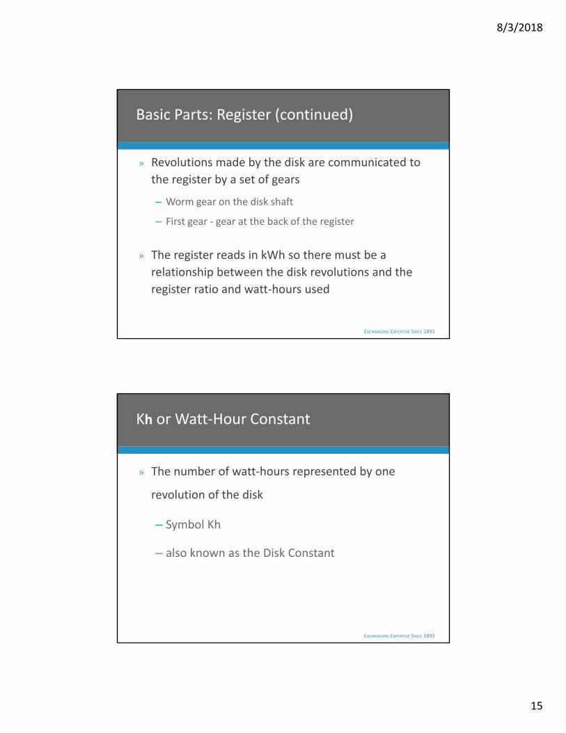
Basic Parts: Register (continued)
» Revolutions made by the disk are communicated to
the register by a set of gears
– Worm gear on the disk shaft
– First gear ‐ gear at the back of the register
» The register reads in kWh so there must be a
relationship between the disk revolutions and the
register ratio and watt‐hours used
EXCHANGING EXPERTISE SINCE 1893
Kh or Watt‐Hour Constant
» The number of watt‐hours represented by one
revolution of the disk
– Symbol Kh
– also known as the Disk Constant
8/3/2018
16
EXCHANGING EXPERTISE SINCE 1893
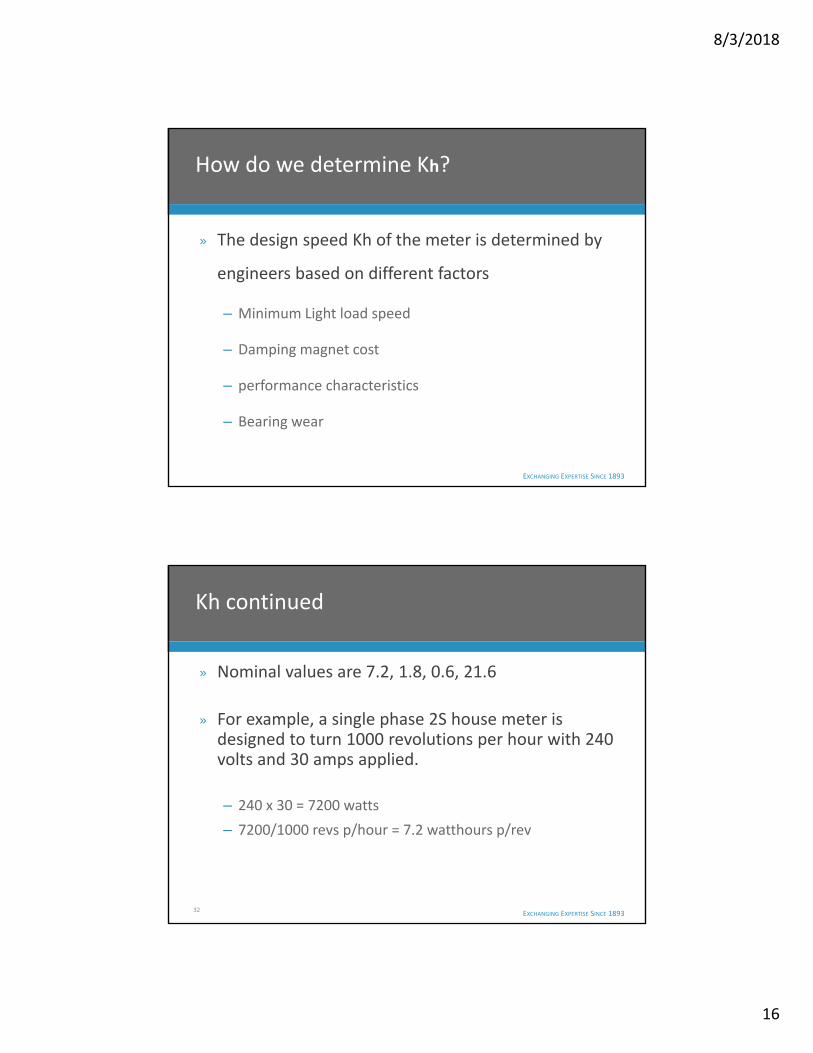
How do we determine Kh?
» The design speed Kh of the meter is determined by
engineers based on different factors
– Minimum Light load speed
– Damping magnet cost
– performance characteristics
– Bearing wear
EXCHANGING EXPERTISE SINCE 1893
» Nominal values are 7.2, 1.8, 0.6, 21.6
» For example, a single phase 2S house meter is designed to turn 1000 revolutions per hour with 240 volts and 30 amps applied.
– 240 x 30 = 7200 watts
– 7200/1000 revs p/hour = 7.2 watthours p/rev
32
Kh continued

8/3/2018
17
EXCHANGING EXPERTISE SINCE 1893
For Modern 1 ø meters the Design Speed is 16 2/3 RPM
» With this we can figure the Kh & Register
ratio of a meter designed for 240V & 30A
» Rated Voltage X Test Amps = Test Watts
240V X 30A = 7200 watts
» 7200 watts for 1 hour =
7200w X 1 Hr = 7200 watt‐hours
» At design speed, test amps & rated voltage
the disk rotational speed is 16 2/3 RPM
EXCHANGING EXPERTISE SINCE 1893
» At 16 2/3 RPM = 50/3 RPM X 60 min
= 1000 Revolutions
» Therefore the number of watt‐hours per disk revolution is:
– 7200 watt‐hours/ 1000 Rev = 7.2 watt‐hours/rev
8/3/2018
18
EXCHANGING EXPERTISE SINCE 1893
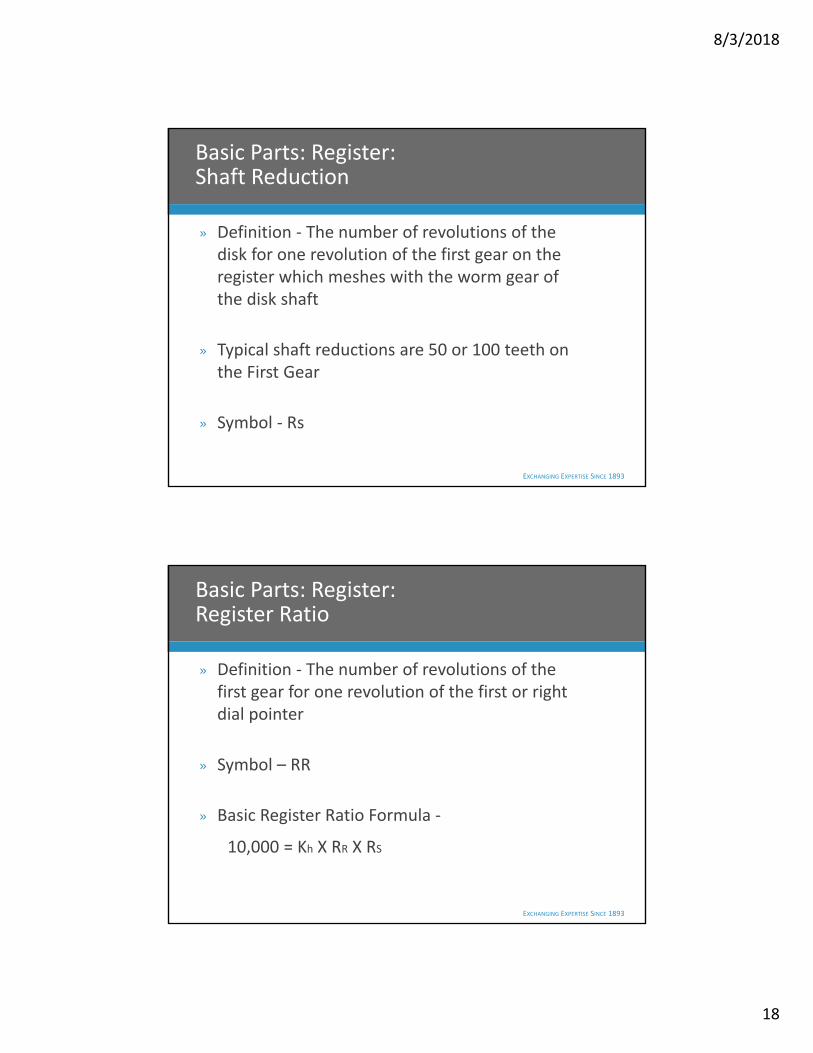
Basic Parts: Register: Shaft Reduction
» Definition ‐ The number of revolutions of the disk for one revolution of the first gear on the register which meshes with the worm gear of the disk shaft
» Typical shaft reductions are 50 or 100 teeth on the First Gear
» Symbol ‐ Rs
EXCHANGING EXPERTISE SINCE 1893
Basic Parts: Register: Register Ratio
» Definition ‐ The number of revolutions of the first gear for one revolution of the first or right dial pointer
» Symbol – RR
» Basic Register Ratio Formula ‐
10,000 = Kh X RR X RS
8/3/2018
19
EXCHANGING EXPERTISE SINCE 1893 37
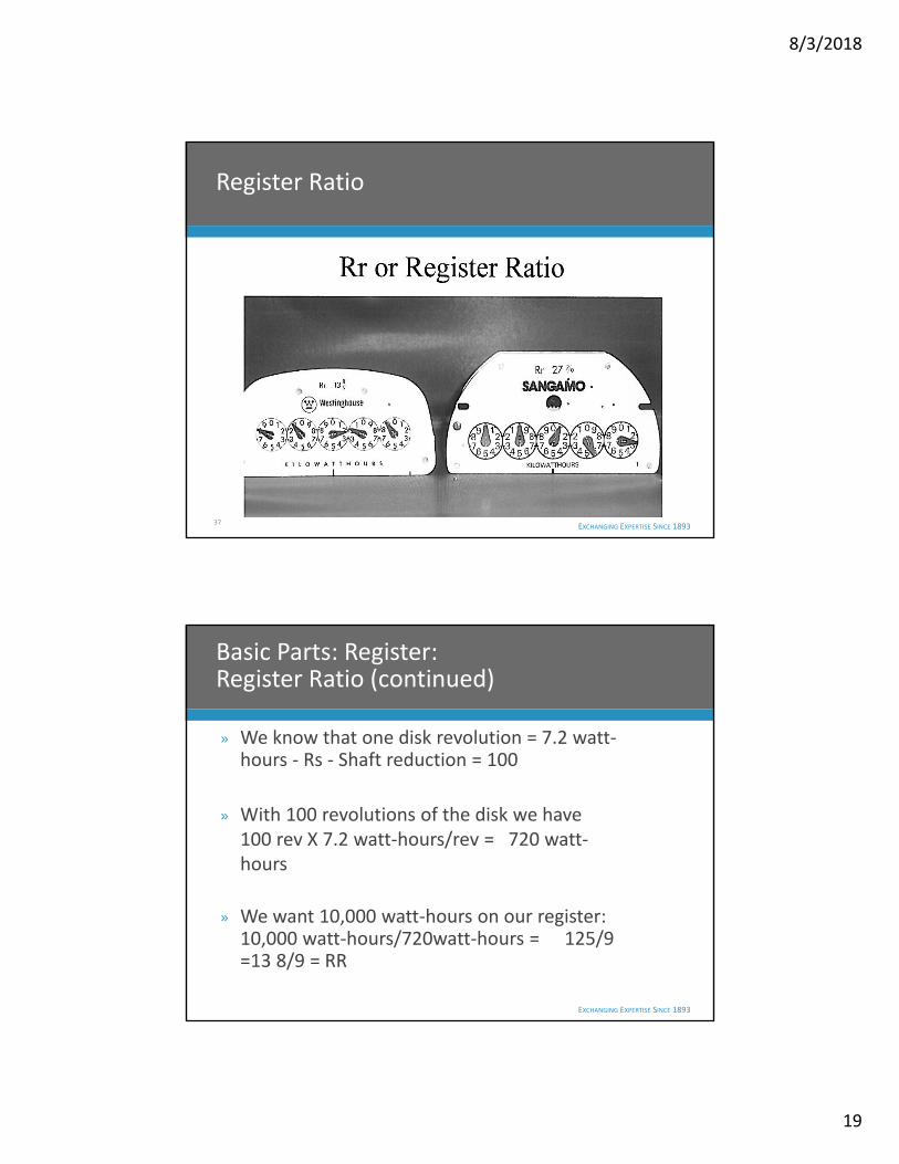
Register Ratio
EXCHANGING EXPERTISE SINCE 1893
Basic Parts: Register: Register Ratio (continued)
» We know that one disk revolution = 7.2 watt‐hours ‐ Rs ‐ Shaft reduction = 100
» With 100 revolutions of the disk we have 100 rev X 7.2 watt‐hours/rev = 720 watt‐hours
» We want 10,000 watt‐hours on our register: 10,000 watt‐hours/720watt‐hours = 125/9 =13 8/9 = RR

8/3/2018
20
EXCHANGING EXPERTISE SINCE 1893
Basic Parts: Register: Gear Ratio
» Definition ‐ The number of revolutions of the disk needed to cause the first pointer to make one complete revolution
» Symbol ‐ RG
» Gear Ratio Formula ‐ RR X RS = RG
13 8/9 X 100Revs = 1388 8/9 Revs
EXCHANGING EXPERTISE SINCE 1893
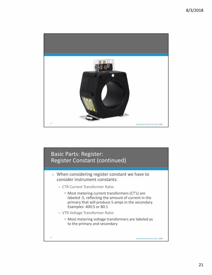
Basic Parts: Register: Register Constant
» Definition ‐ The factor by which the register reading is multiplied to obtain total registration or KWH used
» Also know as ‐ Dial constant, Dial Multiplier or Reading Multiplier
8/3/2018
21
EXCHANGING EXPERTISE SINCE 1893 41
EXCHANGING EXPERTISE SINCE 1893
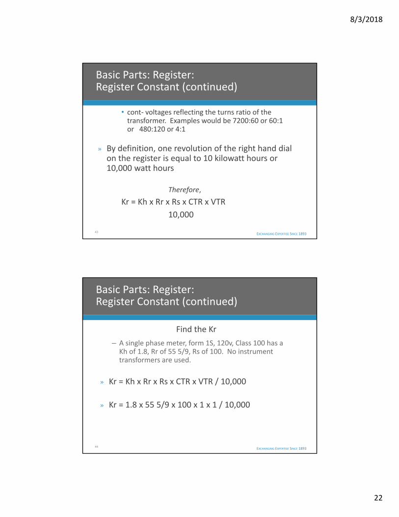
» When considering register constant we have to consider instrument constants:
– CTR Current Transformer Ratio
• Most metering current transformers (CT’s) are labeled :5, reflecting the amount of current in the primary that will produce 5 amps in the secondary. Examples: 400:5 or 80:1
– VTR Voltage Transformer Ratio
• Most metering voltage transformers are labeled as to the primary and secondary
42
Basic Parts: Register: Register Constant (continued)
8/3/2018
22
EXCHANGING EXPERTISE SINCE 1893
• cont‐ voltages reflecting the turns ratio of the transformer. Examples would be 7200:60 or 60:1 or 480:120 or 4:1
» By definition, one revolution of the right hand dial on the register is equal to 10 kilowatt hours or 10,000 watt hours
Therefore,
Kr = Kh x Rr x Rs x CTR x VTR
10,000
43
Basic Parts: Register: Register Constant (continued)
EXCHANGING EXPERTISE SINCE 1893
Find the Kr
– A single phase meter, form 1S, 120v, Class 100 has a Kh of 1.8, Rr of 55 5/9, Rs of 100. No instrument transformers are used.
» Kr = Kh x Rr x Rs x CTR x VTR / 10,000
» Kr = 1.8 x 55 5/9 x 100 x 1 x 1 / 10,000
44
Basic Parts: Register: Register Constant (continued)

8/3/2018
23
EXCHANGING EXPERTISE SINCE 1893
Find the Rr
– You want the Kr to be 1, Kh = 1.8, Rs = 50,
Kr = Kh x Rr x Rs x CTR x VTR / 10,000
1= 1.8 x Rr x 50 x 1 x 1 / 10,000
Rr = 10,000
1.8 x 50
Rr = 111.1111111111 or 111 1/9
45
Basic Parts: Register: Register Constant (continued)
EXCHANGING EXPERTISE SINCE 1893
Last one – Find the Kr
– Kh = 1.8, Rr = 166 2/3, Rs = 50, CTR = 50:5, VTR = 7200:120
Kr = Kh x Rr x Rs x CTR x VTR / 10,000
Kr = 1.8 x 166 2/3 x 50 x 10 x 60 / 10,000
Kr = ?????
46
Basic Parts: Register: Register Constant (continued)
8/3/2018
24
EXCHANGING EXPERTISE SINCE 1893
Meter Calibration and Adjustments
» Disk Adjustment
» Register Mesh
» Full Load Adjustment
» Light Load Adjustment
» Lag Adjustment
EXCHANGING EXPERTISE SINCE 1893
Meter Calibration ‐Disk Adjustment and Register Mesh
» Disk Adjustment
– Using upper and lower bearings center disk in air gap
» Register Mesh
– If equipped adjust gear/shaft mesh for a 30% to 50% mesh between first gear of the register and worm gear of disk shaft

8/3/2018
25
EXCHANGING EXPERTISE SINCE 1893 49
TOPPED GEARS
EXCHANGING EXPERTISE SINCE 1893
Meter Calibration ‐Full Load Adjustment
» Purpose ‐ Adjusts speed of the disk @ rated voltage and Test Amps
» Description ‐ An adjusting screw moves a shunt across the permanent magnet which lets more or less rotation flux to cut across the disk and the disk slows down or speeds up
8/3/2018
26
EXCHANGING EXPERTISE SINCE 1893
Meter Calibration ‐Light Load Adjustment
» Purpose ‐ Adjusts speed of the disk @ rated
voltage and at 10 % of Test Amps
» Description ‐A rectangular plate (brass or copper)
is mounted so that its adjusting motion is at a
right angle to the disk radius. The main air gap
potential flux passes through the plate and
adjusts for shading and to overcome low load
friction.
EXCHANGING EXPERTISE SINCE 1893
Meter Calibration ‐Lag or Power Factor Adjustment
» Purpose ‐ Adjusts the phase angle of the potential coil flux to lag the applied voltage by 90 degrees
» Description ‐ The Lag adjustment is a metal plate attached to the potential coil core. The resistance of the plate adjusts the power factor. This adjustment is set at the factory and normally does not need any further adjustment
8/3/2018
27
EXCHANGING EXPERTISE SINCE 1893
Break Time
» 10 minutes
EXCHANGING EXPERTISE SINCE 1893
Meter Compensations
» Voltage
» Overload
» Temperature Class I
» Temperature Class II
» Frequency
8/3/2018
28
EXCHANGING EXPERTISE SINCE 1893
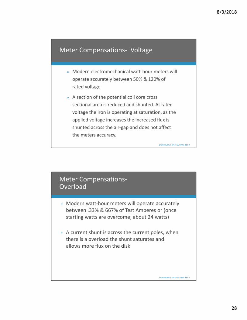
Meter Compensations‐ Voltage
» Modern electromechanical watt‐hour meters will
operate accurately between 50% & 120% of
rated voltage
» A section of the potential coil core cross
sectional area is reduced and shunted. At rated
voltage the iron is operating at saturation, as the
applied voltage increases the increased flux is
shunted across the air‐gap and does not affect
the meters accuracy.
EXCHANGING EXPERTISE SINCE 1893
Meter Compensations‐Overload
» Modern watt‐hour meters will operate accurately between .33% & 667% of Test Amperes or (once starting watts are overcome; about 24 watts)
» A current shunt is across the current poles, when there is a overload the shunt saturates and allows more flux on the disk
8/3/2018
29
EXCHANGING EXPERTISE SINCE 1893
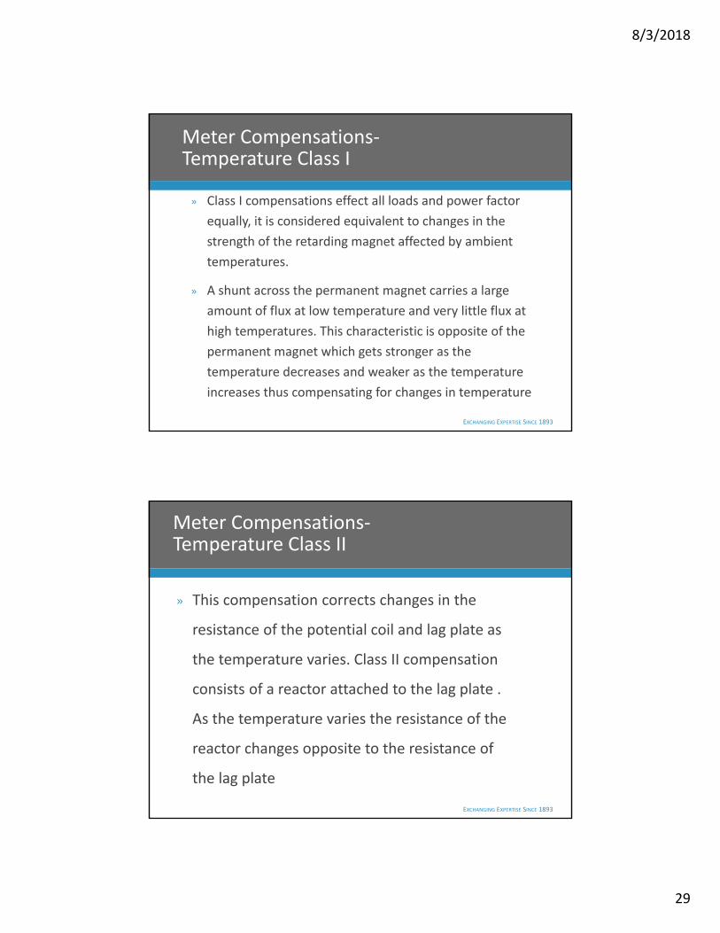
Meter Compensations‐Temperature Class I
» Class I compensations effect all loads and power factor
equally, it is considered equivalent to changes in the
strength of the retarding magnet affected by ambient
temperatures.
» A shunt across the permanent magnet carries a large
amount of flux at low temperature and very little flux at
high temperatures. This characteristic is opposite of the
permanent magnet which gets stronger as the
temperature decreases and weaker as the temperature
increases thus compensating for changes in temperature
EXCHANGING EXPERTISE SINCE 1893
Meter Compensations‐Temperature Class II
» This compensation corrects changes in the
resistance of the potential coil and lag plate as
the temperature varies. Class II compensation
consists of a reactor attached to the lag plate .
As the temperature varies the resistance of the
reactor changes opposite to the resistance of
the lag plate

8/3/2018
30
EXCHANGING EXPERTISE SINCE 1893
Meter Compensations‐Frequency
» Because of frequency stability of modern
electrical systems, variations in meter accuracy
due to frequency variations are negligible
EXCHANGING EXPERTISE SINCE 1893
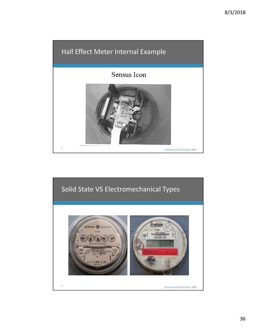
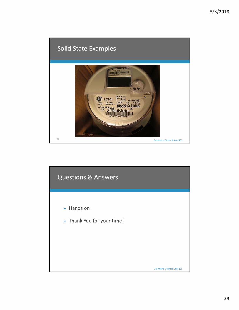
» Benefits
– Weight
– Cost
– Accuracy
– Programmability and additional functions
» Drawbacks
– Customer concerns
– Half life
– Adjustability
60
Solid State VS Electromechanical

8/3/2018
31
EXCHANGING EXPERTISE SINCE 1893
» Current Sensing (CT)
– GE ‐ KV2C and I‐210
– Landis and Gyr ‐ Alf
– ABB ‐ A1D
» Hall Effect
– Itron ‐ C1S
– Icon Sensus ‐ iSO1
61
Types of Solid State Meters
EXCHANGING EXPERTISE SINCE 1893
» Perhaps the easiest to understand in terms of
an electronic meter. Current sensing meters
work on the same principle as a transformer
rated service. Current passed through the
current coil or primary side is reduced based on
the multiplier relationship established by the
manufacturer to the output or secondary side
of the CT.
62
Current Sensing (CT) Meters

8/3/2018
32
EXCHANGING EXPERTISE SINCE 1893
» This measured (secondary) current is then sent
to the microprocessor to be calculated with
the voltage and service type. The
corresponding load, KW, KWh, and any other
requested measurements are produced and
sent to the readout for display.
63
Current Sensing (CT) Meters (continued)
EXCHANGING EXPERTISE SINCE 1893 64
Current Sensing (CT) Meter Internal Example
8/3/2018
33
EXCHANGING EXPERTISE SINCE 1893
» A Hall‐effect meter is an electronic device that provides a digital readout of the magnetic field strength in gauss or tesla units. The meters use a very small conductor or semiconductor element at the tip of the probe. Electric current is passed through the conductor. In a magnetic field, a force is exerted on the moving electrons which tends to push them to one side of the conductor.
65
Hall Effect
EXCHANGING EXPERTISE SINCE 1893
» A buildup of charge at the sides of the conductors will balance this magnetic influence, producing a measurable voltage between the two sides of the conductor. The presence of this measurable transverse voltage is called the Hall‐effect after Edwin H. Hall, who discovered it in 1879
66
Hall Effect (continued)

8/3/2018
34
EXCHANGING EXPERTISE SINCE 1893 67
Hall Effect
EXCHANGING EXPERTISE SINCE 1893
» Vh = I B Rh / b
» Where:Vh is the voltage generated.I is the applied direct current.B is the component of the magnetic field that is at a right angle to the direct current in the Hall element.Rh is the Hall Coefficient of the Hall element.b is the thickness of the Hall element.
68
Hall Effect (continued)

8/3/2018
35
EXCHANGING EXPERTISE SINCE 1893 69
Hall Effect (continued)
EXCHANGING EXPERTISE SINCE 1893 70
Hall Effect Meter Internal Example
8/3/2018
36
EXCHANGING EXPERTISE SINCE 1893 71
Hall Effect Meter Internal Example
EXCHANGING EXPERTISE SINCE 1893 72
Solid State VS Electromechanical Types

8/3/2018
37
EXCHANGING EXPERTISE SINCE 1893 73
Solid State Examples
EXCHANGING EXPERTISE SINCE 1893 74
Electromechanical Types

8/3/2018
38
EXCHANGING EXPERTISE SINCE 1893 75
Solid State Examples
EXCHANGING EXPERTISE SINCE 1893 76
Solid State Examples
8/3/2018
39
EXCHANGING EXPERTISE SINCE 1893 77
Solid State Examples
EXCHANGING EXPERTISE SINCE 1893
Questions & Answers
» Hands on
» Thank You for your time!


![SL3488 instruction manual -V1[1].52-20080429 · Instruction Manual Rev 1.2 ... will be affected the meter’s working and reduce the meter’s life or cause some malfunctions. ...](https://static.fdocuments.us/doc/165x107/5c91f5ae09d3f26a458bae12/sl3488-instruction-manual-v1152-instruction-manual-rev-12-will-be.jpg)