single page max cataloge V1 26 02 16 - maxformwork.commaxformwork.com/pdf/Max Deck.pdfDELHI NCR...
28
MAX DECK Slab Formwork System WWW.MAXFORMWORK.COM UNIMAX INTERNATIONAL (An ISO 9001:2008 Certified Company)
Transcript of single page max cataloge V1 26 02 16 - maxformwork.commaxformwork.com/pdf/Max Deck.pdfDELHI NCR...

MAX DECK
Slab Formwork System
WWW.MAXFORMWORK.COM
UNIMAX INTERNATIONAL(An ISO 9001:2008 Certified Company)


INNOVATIVE DESIGN
ASSURING QUALITY
EXCELLENT SERVICE
UNIMAX INTERNATIONAL
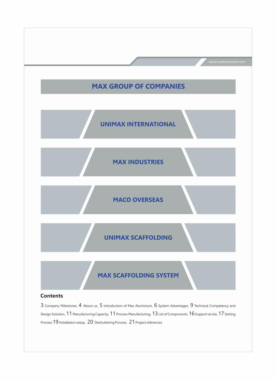
Contents
3 Company Milestones, 4 About us, 5 Introduction of Max Aluminium, 6 System Advantages, 9 Technical Competency and
Design Solution, 11 Manufacturing Capacity, 11 Process Manufacturing, 13 List of Components, 16 Support at site, 17 Setting
Process 19 Installation setup, 20 Deshuttering Process, 21 Project references
MAX GROUP OF COMPANIES
MAX INDUSTRIES
MACO OVERSEAS
UNIMAX SCAFFOLDING
MAX SCAFFOLDING SYSTEM
www.maxformwork.com

We embarked on a Mission Journey 26 years ago in 1989 with a vision to provide the best of the global technologies for Indian
Construction Industry. It may be easier to stick to the conventional construction methods, while the industry has glittered with
glorious changes the world over. We took this challenge by adopting through our innovative greener techniques to develop an
indigenous, yet affordable and viable, import substitute for the Indian Construction Industry, of course, beneficial to the urban
environment.
The Max formwork has been consistently striving to work towards the requirement of its customers while bringing the innovative
solutions with the emerging trends in the construction industry with its experienced and dedicated personnel at its R & D center.
We believe there is always an opportunity to bring automation and better system such as Robots, improvised welding system and
new technologies from other developed industrial countries. With the same vision, we are soon going to introduce Stir Fabrication
Welding Techniques to Indian Construction Industry which is being used by the Aerospace Industry globally that will set the
benchmark in India.
We also think beyond tall buildings hence considering the future of construction development which gives us a wider perspective
and fresh ideas when it comes to design the living spaces such as condos, skyscrapers, skylines and office spaces being built in major
cities around the world.
Architects and designers have given us exciting ideas which will define the way we live and the kind of living that the next generation
will experience. More importantly, as these buildings are constructed, experts should ensure that every material and every action
taken in the construction process will minimize the hazards of environmental damages. And that's where MAX Formwork has
expertise to bring the Innovative Solution at your doorstep to challenge the future of construction.
Mr. Nitin SharmaMD
Mr. Rajesh SharmaCMD
www.maxformwork.com

DELHI NCR
HYDERABAD
BENGALURU
MUMBAI
RAJASTHAN
Max Group Factories
Plant No 1 - Plot No. 1&10, Sector 7,SIDCUL, Integrated Industrial Estate Rudrapur, Uttarakhand (India)
Plant No 2 - 1291-92, HSIDC, Industrial Area, Rai, Sonepat, Haryana (India)
Plant No 3 - 1293-94, HSIDC, Industrial Area, Rai, Sonepat, Haryana (India)
Company MilestonesWe believe in kaizen, hence continuous learning helps us to adopt the best industry practices to provide best of the services to our
customers. It has been a great journey while providing State-of-the-art services to various customers while setting up standards for
the Industry with our best practices developed over a period of time.
PAN India Presence
of MAX Group
1989 Establishment of Max Group
1990 Starting of Forging and casting of scaffolding component
1993 Starting of Export of Scaffolding component to Middle East
1997 Starting of manufacturing of Steel Formwork system
2004 Establishment of hiring division of Formwork material in India
2009 Developed Max Aluminium Formwork system
2010 Establishment of Mass Aluminium Formwork Production system for monthly capacity of 20,000 Sqm
2011 Completion of First formwork order of 11,000 Sqm Aluminium Formwork system
2012 Completion of second plant for the manufacturing of different Formwork system
2014 Developed MaxDeck Formwork system
2015 Developed MaxTable Formwork system
2016 Initiated R&D on automatic climbing system
UTTARAKHAND
KOLKATA
3
www.maxformwork.com

Unimax International is an established organization in Aluminium Formwork System serving the construction industry
with updated and customized solutions which are environment friendly.
An ISO 9001:2008 certified company having two state-of-the-Art manufacturing units each in Sonepat, Haryana as well as
in Pantnagar, Uttrakhand are well supported by in-house Research & Development department.
Unimax with continuous innovations using latest technology and System, highly professional project support team
committed to provide Formwork System which is not only of high quality but also enables our client to achieve faster slab
cycles at competitive prices. We expertise in designing the Formwork system by using high end software such as Staad,
Revit and AutoCAD to meet our specific requirement. Today our satisfied clients include some of the reputed builders
Developers, Corporate and Construction Companies. As a reflection of our Quality, after sales Services and Customer
support, we have been able to retain our clients who have been awarding us with repeated orders.
4
About us
www.maxformwork.com

Introductionwww.maxformwork.com
5
Why should you
Choose Max Deck
Max Deck is hand – set panelised slab Formwork system that offers three methods of
Forming system –covering virtually any slab job in one and same system. Using the same
parts avoids assembly error. The number of Props defined by the system ensuring safety
and quick assembly.
5

6
Salient Features of MaxDeckwww.maxformwork.com
» Zero assembly error
» Fewer components makes the assembly easy
» Integrated or Separated facing
» Compensation area minimized
» Suitable for any slab height or any slab thickness
» Early stripping for fast pour cycle
» Facilitate safe Deshuttering which prevent damaging of Shuttering material as well
as structure
» Very low number of props required per Sqm. This makes it possible to use larger
sections of profile, and increase the distance between props.
» Fair finish surface does not require plaster
» Crane-independent
System Component
13
L
170
107
147
40
10023 23
L
W
L
91
Eq Eq Eq Eq
40
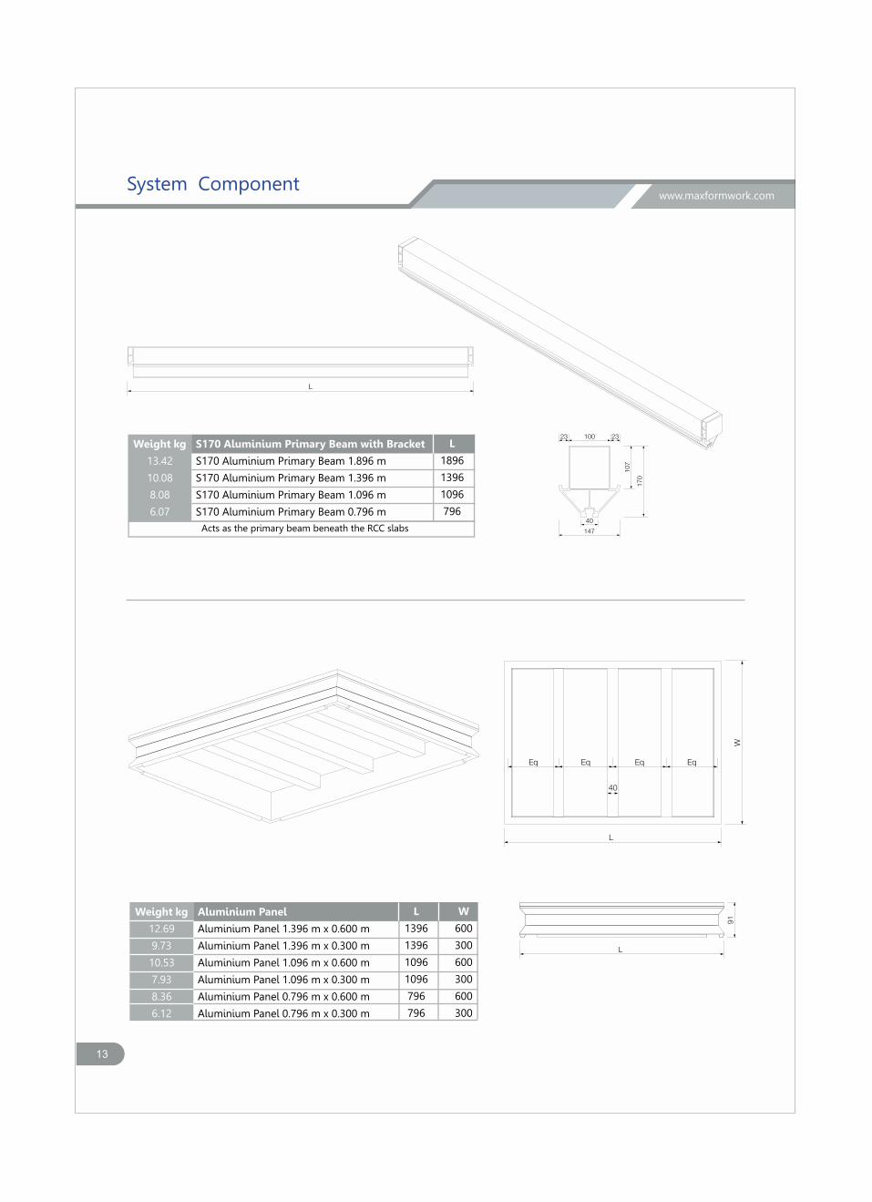
S170 Aluminium Primary Beam with Bracket
S170 Aluminium Primary Beam 1.896 m
S170 Aluminium Primary Beam 1.396 m
S170 Aluminium Primary Beam 1.096 m
S170 Aluminium Primary Beam 0.796 m
Acts as the primary beam beneath the RCC slabs
Weight kg
13.42
10.08
8.08
6.07
L
1896
1396
1096
796
Aluminium Panel
Aluminium Panel 1.396 m x 0.600 m
Aluminium Panel 1.396 m x 0.300 m
Aluminium Panel 1.096 m x 0.600 m
Aluminium Panel 1.096 m x 0.300 m
Aluminium Panel 0.796 m x 0.600 m
Aluminium Panel 0.796 m x 0.300 m
Weight kg
12.69
9.73
10.53
7.93
8.36
6.12
L
1396
1396
1096
1096
796
796
W
600
300
600
300
600
300
www.maxformwork.com
System Component
13
L
L
6210
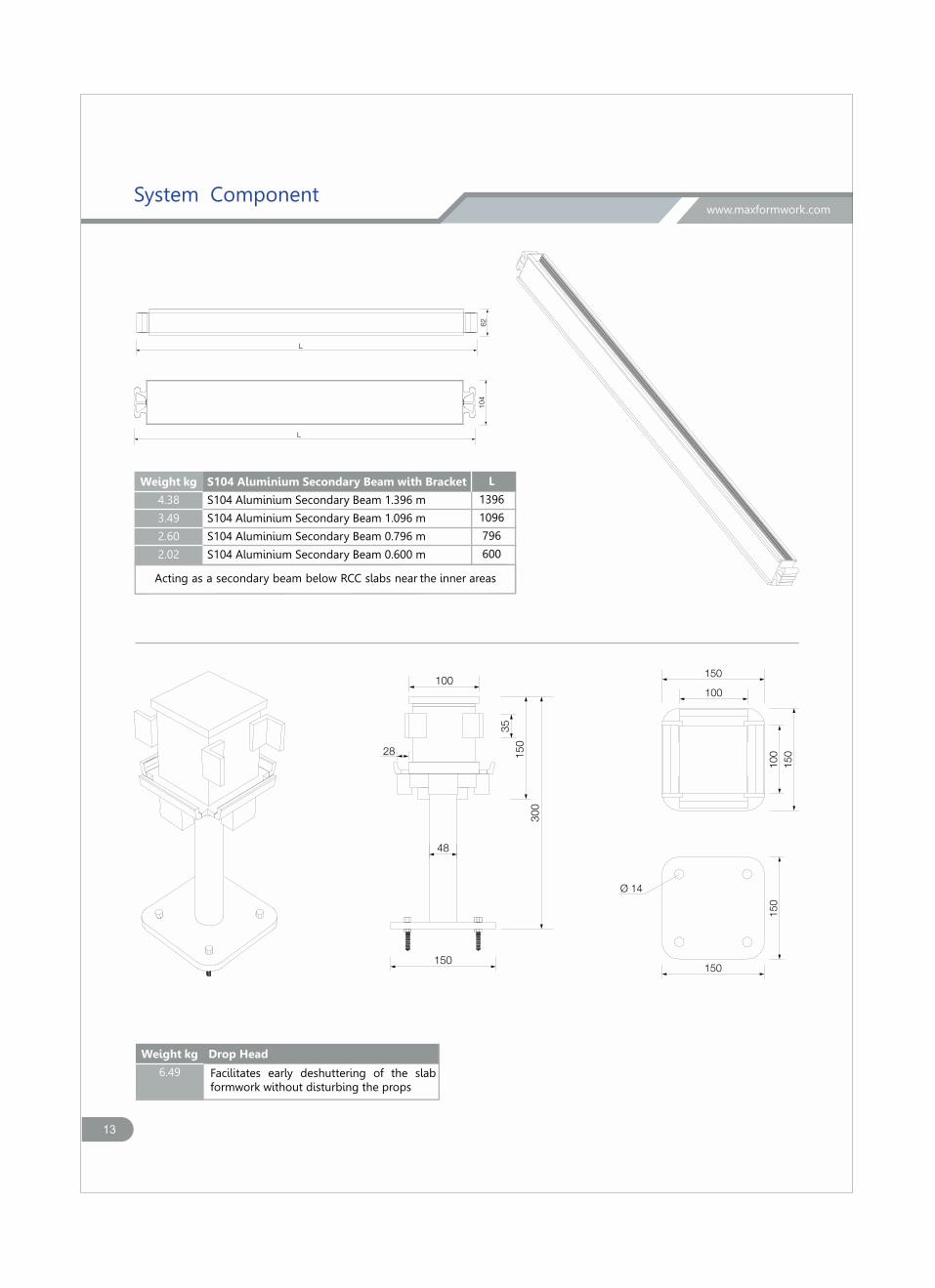
4S104 Aluminium Secondary Beam with Bracket
S104 Aluminium Secondary Beam 1.396 m
S104 Aluminium Secondary Beam 1.096 m
S104 Aluminium Secondary Beam 0.796 m
S104 Aluminium Secondary Beam 0.600 m
Acting as a secondary beam below RCC slabs near t he inner areas
Weight kg
4.38
3.49
2.60
2.02
L
1396
1096
796
600
300
150
100
28
48
150
35
100
150
150
100
150
150
Ø 14
Drop Head Weight kg
6.49 Facilitates early deshuttering of the slab formwork without disturbing the props
www.maxformwork.com

14
L
14
70
40
150
8642
15 15
3
22
Acts as the primary beam beneath the RCC beam
S150 Aluminium Beam
S150 Aluminium Beam 2.500 m
S150 Aluminium Beam 2.000 m
S150 Aluminium Beam 1.500 m
S150 Aluminium Beam 1.200 m
S150 Aluminium Beam 0.900 m
Weight kg
8.98
7.18
5.39
4.31
3.23
L
2500
2000
1500
1200
900
L
104
62
40
38
39
30
3
11 11
Acts as the secondary beam beneath the RCC slabs
S140 Aluminium Secondary Beam
S104 Aluminium Secondary Beam 2.000 m
S104 Aluminium Secondary Beam 1.500 m
S104 Aluminium Secondary Beam 1.200 m
Weight kg
5.84
4.38
3.49
L
2000
1500
1200
www.maxformwork.comSystem Component

16
50
50 121
3838
45
Universal Clamp
Connects the primary and the secondamrye mbers in an RCC beam formwork
Acts as a staging member below the RCC slab and the beam
L m
in -
L m
ax
45
1010
Ø 70
Ø 60
Ø 9
150
150
Ø 14
Adjustable Steel Prop
Adjustable Steel Prop Ap375
Adjustable Steel Prop AP270
Weight kg
28.06
22.05
L min
2000
1500
L max
3750
2700
Weight kg
0.43
www.maxformwork.comSystem Component
16
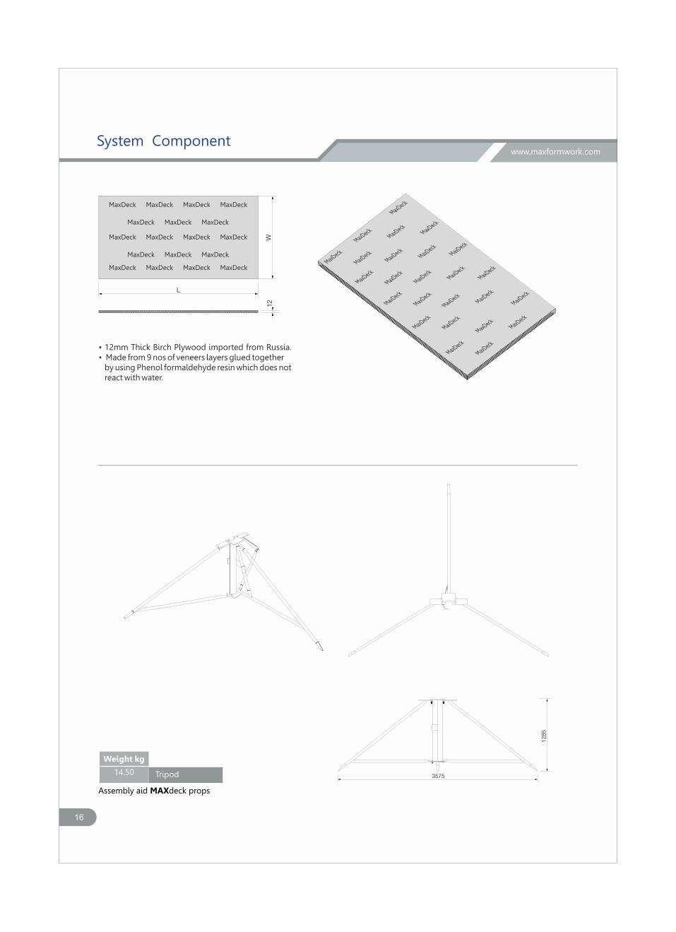
L
W12
MaxDeck
MaxDeck
MaxDeck
MaxDeck
MaxDeck
MaxDeck
MaxDeck
MaxDeck
MaxDeck
MaxDeck
MaxDeck
MaxDeck
MaxDeck
MaxDeck
MaxDeck
MaxDeck
MaxDeck
MaxDeck
MaxDeck
MaxDeck
MaxDeck
MaxDeck
MaxDeck
MaxDeck
MaxDeck
MaxDeck MaxDeck MaxDeck MaxDeck
MaxDeck MaxDeck MaxDeck
MaxDeck MaxDeck MaxDeck MaxDeck
MaxDeck MaxDeck MaxDeck
MaxDeck MaxDeck MaxDeck MaxDeck
• 12mm Thick Birch Plywood imported from Russia.• Made from 9 nos of veneers layers glued together by using Phenol formaldehyde resin which does not react with water.
3575
1285
Tripod
Weight kg
14.50
Assembly aid MAXdeck props
www.maxformwork.comSystem Component

Assembly Sequence
16
The marking will be done with the required span with
the maximum span upto the lenghth of the main beam
Next the Props will be placed over the markings and
kept in position with the help of the tripod
The set of props will be placed over the markings with
the help of the tripod for the specified area.
Once all the props area assembled at the location then
the main beam will be installed over the drop head
which was already placed above the prop.
www.maxformwork.com

16
After the installation of the Primary beam over the
drop head the secondary beam will be placed over the
primary beam
Once all the beams are placed then the aluminium
panels fitted with the densified ply wood will be placed
over the beams.
The panels are very light in weight which can be easily
lift by a person and place it over the beam.
The final step will the checking the plumb of the props
to ensure the surface is perfectly levelled.
www.maxformwork.comAssembly Sequence

Deshuttering Process
20
Unclamp the drophead by the steps as mentioned in
the drophead down step procedure leaving full
support to the slab through the props.
Once all the drop head have come down then remove
all the aluminium panels from the down.
Then remove all the secondary beam Then remove the primary beam leaving the props to
support the slab.
www.maxformwork.com

16
www.maxformwork.comDeshuttering Process
Engineering and Technology
• As a manufacturer, Maxformwork leads in the field of quality technology, developing and manufacturing high-qualityformwork systems such as MaxDeck. Our plants at Rudrapur (Utthrakand) and Delhi have the State of the art manufacturing facilities. Each components of MaxDeck passes through different rigours quality checks during manufacturing.
• We are pioneered in the closed hollow profile. The closed profile are much more stable and more robust in lateral torsional buckling compare to open counterpart. Above all concrete doesn’t get caught in closed profile. This improves concrete finish and reduces cleaning effort.
• MaxDeck panels are light-weight, yet sturdy. The ergonomic grip profile allows for easy handling with just one worker. Large slab areas can be assembled by hand.
• We use latest software for designing and drawing such as Staad pro, Revit and Autocad which gives real time design solution compare to old convectional designing method. We take utmost care for the safety of Formwork and structure in our designs.
• Each and every component of MaxDeck has been tested in the state of the art laboratory at IIT Chennai. All the product has been tested together as a system and individually for the better understanding of load capacity and failure pattern.
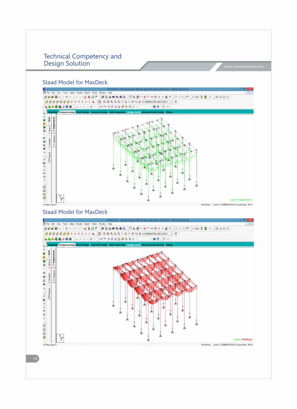
• Since MaxDeck facilitate the early Deshuttering of the Slab without disturbing the props hence we provide the detailed design calculation along with Staad models not only for the MaxDeck but also for the Deshuttering. Our designs can be verified by any of the reputed institute such as IIT or structural consultants.
• The all components of MaxDeck has been designed according to the guidelines given in ACI 347 and BS 5957.
9
www.maxformwork.com
10
Staad Model for MaxDeck
Staad Model for MaxDeck
www.maxformwork.com
Technical Competency and Design Solution

10
Design table and charts
Design table
� The values mentioned in ( ) mentiones sagging bending moment in the beam As per ACI 347, l/360 has been considered as the allowable defl ection.
0.10 25 2.50 1.50 0.50 4.50 2.00 1.50 (3.49) (0.38) 14.63 0.12 25 3.00 1.50 0.50 5.00 2.00 1.50 (3.85) (0.42) 16.14
0.14 25 3.50 1.50 0.50 5.50 2.00 1.50 (4.22) (0.46) 17.65
0.16 25 4.00 1.50 0.50 6.00 2.00 1.50 (4.59) (0.50) 19.17 0.18 25 4.50 1.50 0.50 6.50 2.00 1.50 (4.95) (0.54) 20.68 0.20 25 5.00 1.50 0.50 7.00 2.00 1.50 (5.32) (0.58) 22.20
0.22 26 5.72 1.50 0.50 7.72 2.00 1.20 (4.67) (0.40) 19.60 0.24 26 6.24 1.50 0.50 8.24 2.00 1.20 (4.97) (0.42) 20.86
0.26 26 6.76 1.50 0.50 8.76 2.00 1.20 (5.28) (0.45) 22.12
0.28 26 7.28 1.50 0.50 9.28 2.00 1.20 (5.58) (0.47) 23.38 0.30 26 7.80 2.00 0.50 10.3 1.50 1.20 (3.52) (0.53) 19.63
0.32 26 8.32 2.00 0.50 10.82 1.50 1.20 (3.70) (0.55) 20.58
0.34 26 8.84 2.00 0.50 11.34 1.50 1.20 (3.87) (0.58) 21.54 0.36 26 9.36 2.00 0.50 11.86 1.50 1.20 (4.04) (0.60) 22.49
0.38 26 9.88 2.00 0.50 12.38 1.50 0.90 (3.64) (0.34) 18.62 0.40 26 10.40 2.00 0.50 12.9 1.50 0.90 (3.79) (0.36) 19.36
0.42 26 10.92 2.00 0.50 13.42 1.50 0.90 (3.93) (0.37) 20.12
0.44 26 11.44 2.00 0.50 13.94 1.50 0.90 (4.08) (0.39) 20.87 0.46 26 11.96 2.00 0.50 14.46 1.50 0.90 (4.23) (0.40) 21.63
0.48 26 12.48 2.00 0.50 14.98 1.50 0.90 (4.38) (0.41) 22.38
Slab
0.50 26 13.00 2.00 0.50 15.5 1.50 0.90 (4.53) (0.43) 23.13
Thickness
(m)
Density of Concrete
(kN/m3)
Load due to concrete
[q](kN/m2)
Live Load[p]
(kN/m2)
Self weight of the formwork
[g](kN/m2)
Total load[q+p+g](kN/m2)
Prop spacing
[a](m)
Primary beam
spacing[b](m)
Bending moment in
primary beam(kN-m�)
Bending moment in
panel(kN-m�)
Load in props(kN)
www.maxformwork.com
Technical Competency and Design Solution
10
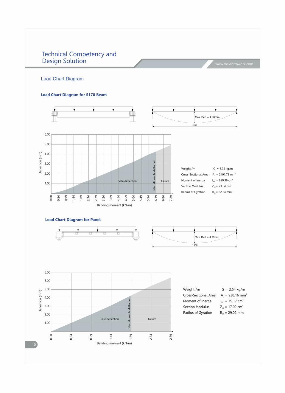
Load Chart Diagram for S170 Beam
Load Chart Diagram for Panel
Load Chart Diagram
Weight /m G = 6.75 kg/m
2Cross-Sectional Area A = 2491.75 mm
4Moment of Inertia I = 690.36 cmXX
3Section Modulus Z = 73.04 cmXX
Radius of Gyration R = 52.64 mmXX
Weight /m G = 2.54 kg/m2Cross-Sectional Area A = 938.16 mm
4Moment of Inertia I = 79.17 cmXX
3Section Modulus Z = 17.02 cm XX
Radius of Gyration R = 29.02 mmXX
Max. Defl = 4.29mm
1500
Max. Defl = 4.28mm
2000
www.maxformwork.com
Technical Competency and Design Solution
1.00
2.00
3.00
4.00
5.00
6.00
Bending moment (kN-m)
Defl
ect
ion
(m
m)
0.5
4
0.0
0
0.9
9
1.4
4
2.3
4
2.7
9
3.2
4
3.6
9
4.1
4
4.5
9
5.0
4
5.4
9
5.9
4
6.3
9
6.8
4
7.2
9
1.8
9
Safe defl ection
Max.
allo
wab
le d
efl
ect
ion
Failure
Defl
ect
ion
(m
m)
Bending moment (kN-m)
0.5
4
0.0
0
0.9
9
1.4
4
2.3
4
2.7
9
1.8
9
1.00
2.00
3.00
4.00
5.00
6.00
6.00
Max.
allo
wab
le d
efl
ect
ion
FailureSafe defl ection
10
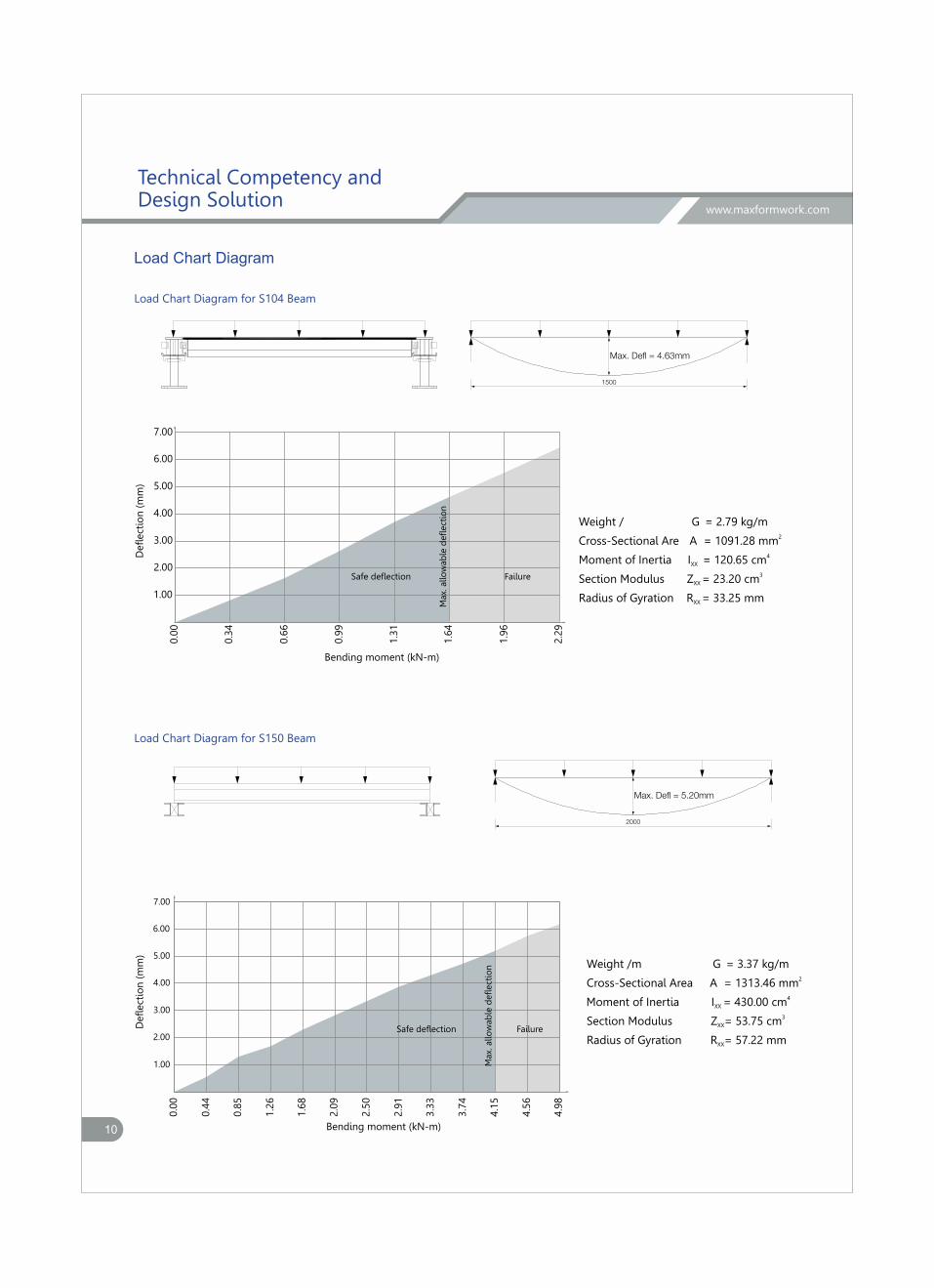
Load Chart Diagram for S150 Beam
Load Chart Diagram for S104 Beam
Weight / G = 2.79 kg/m2Cross-Sectional Are A = 1091.28 mm
4Moment of Inertia I = 120.65 cmXX
3Section Modulus Z = 23.20 cmXX
Radius of Gyration R = 33.25 mmXX
Max. Defl = 4.63mm
1500
Weight /m G = 3.37 kg/m2Cross-Sectional Area A = 1313.46 mm
4Moment of Inertia I = 430.00 cmXX
3Section Modulus Z = 53.75 cmXX
Radius of Gyration R = 57.22 mmXX
Max. Defl = 5.20mm
2000
Load Chart Diagram
www.maxformwork.com
Technical Competency and Design Solution
Bending moment (kN-m)
Defl
ect
ion
(m
m)
0.3
4
0.0
0
0.6
6
0.9
9
1.3
1
1.6
4
1.9
6
2.2
9
1.00
2.00
3.00
4.00
5.00
6.00
7.00M
ax.
allo
wab
le d
efl
ect
ion
FailureSafe defl ection
Bending moment (kN-m)
Defl
ect
ion
(m
m)
0.4
4
0.0
0
0.8
5
1.2
6
1.6
8
2.0
9
2.5
0
2.9
1
3.3
3
3.7
4
4.1
5
4.5
6
4.9
8
1.00
2.00
3.00
4.00
5.00
6.00
7.00
Max.
allo
wab
le d
efl
ect
ion
FailureSafe defl ection
10
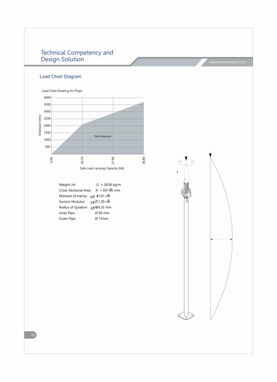
Load Chart Diagram
Weight /m G = 28.06 kg/m
Cross-Sectional Area A = 691.65 mm2
Moment of Inertia IXX = 41.01 cm4
Section Modulus ZXX = 11.39 cm3
Radius of Gyration RXX = 24.35 mm
Inner Pipe Ø 60 mm
Outer Pipe Ø 72mm
www.maxformwork.com
Technical Competency and Design Solution
Load Chart Drawing for Props
0.0
0
28.1
9
27.9
6
26.8
0
Safe Load carrying Capacity (kN)
500
1000
1500
2000
2500
Ext
en
sio
n (
mm
)
3000
3500
4000
Safe Extension


H.O. :Plot No- 312, Pkt. G-21, Sec-7, Rohini, New-Delhi-85.(India)
Sales: +91 9810298430, +91 9717392200/01 Direct: +91 9810598450, +91 9810598430
E-mail - [email protected], [email protected]
[email protected]/[email protected]
web site - www.maxformwork.com
Works: Plot No. 1&10, Sector 7,SIDCUL, Integrated Industrial Estate Rudrapur, Uttrakhand (India)
Mob: +91 9759003519