Simulink tutorial - Asian Institute of...
52
Simulink tutorial
Transcript of Simulink tutorial - Asian Institute of...

Simulink tutorial

Example of a simple Simulink program
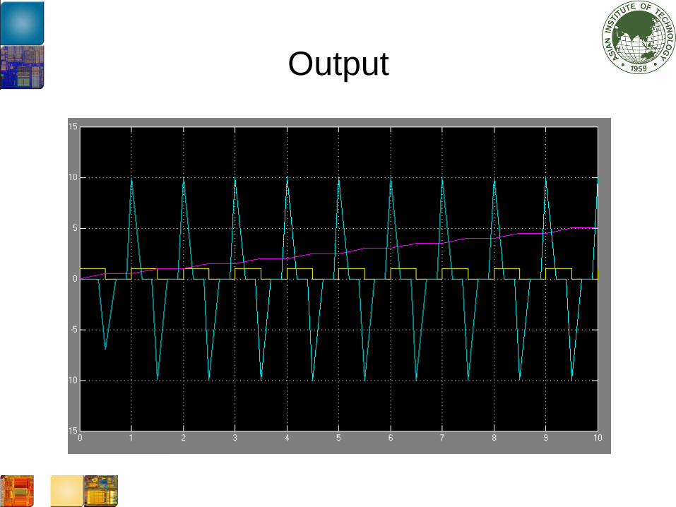
Output

Basic Simulink Block

Inport, Outport, and Subsystem blocks
• Inports are port that serve as links from outside
a system into the system
• Outports serve as a link from the system to the
outside
• A subsystem represents a subsystem of the
system that contains it
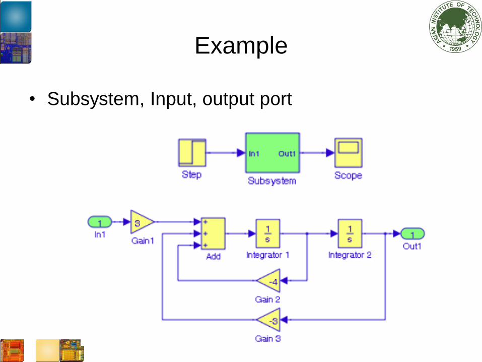
Example
• Subsystem, Input, output port
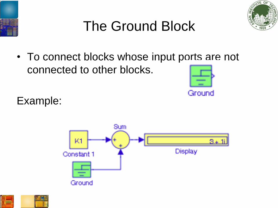
The Ground Block
• To connect blocks whose input ports are not
connected to other blocks.
Example:
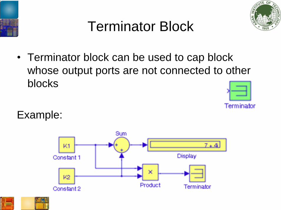
Terminator Block
• Terminator block can be used to cap block
whose output ports are not connected to other
blocks
Example:

Constant and Product Blocks
• The constant block is used to define a real or
complex value. The block accepts scalar, vector
(1-D array), or matrix (2-D array)
• The Product block performs multiplication or
division of its inputs.

Example of the constant and product
blocks

The Divide Block
• We can the set the product to be the divide block.

The Scope Block
• The scope block displays waveforms as
functions of simulation time. The scope block
can have multiple y-axes with a common time
range

The Bus Creator and Bus Selector Blocks
• We use Bus Creator blocks to create signal
buses similar to the multiplexer.
• We use Bus Selector blocks to access the
components of a bus similar to the demultiplexer
• Bus creator and Bus selector blocks are used
with bus signal. Mux and Demux are used with
vectors

Example of Bus Creator
y(t) = sin(2*t)
diff_y(t)=2*cos(2*t)
tnt_y(t)=-1/2*cos(2*t)

Output waveform
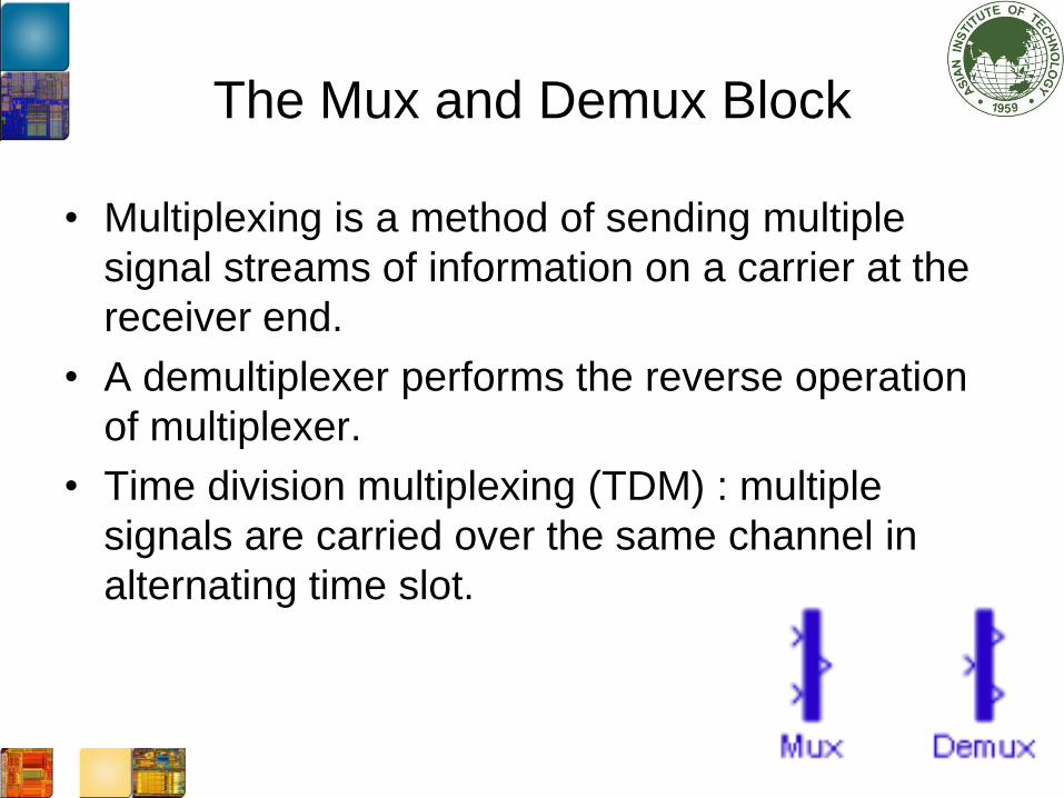
The Mux and Demux Block
• Multiplexing is a method of sending multiple
signal streams of information on a carrier at the
receiver end.
• A demultiplexer performs the reverse operation
of multiplexer.
• Time division multiplexing (TDM) : multiple
signals are carried over the same channel in
alternating time slot.

Example of multiplexing

Digital Mux-Demux pair

Digital Mux-Demux pair

Example of the Demux

Switch Box
• The switch will output the first input or the third
input depending on the value of the second
input.
• The second input is called the control input
specified by the Function Block Parameters
the following options are available:
u2 >= threshold,
u2 > threshold,
u2 ~= 0

The example of Switch Block

The output
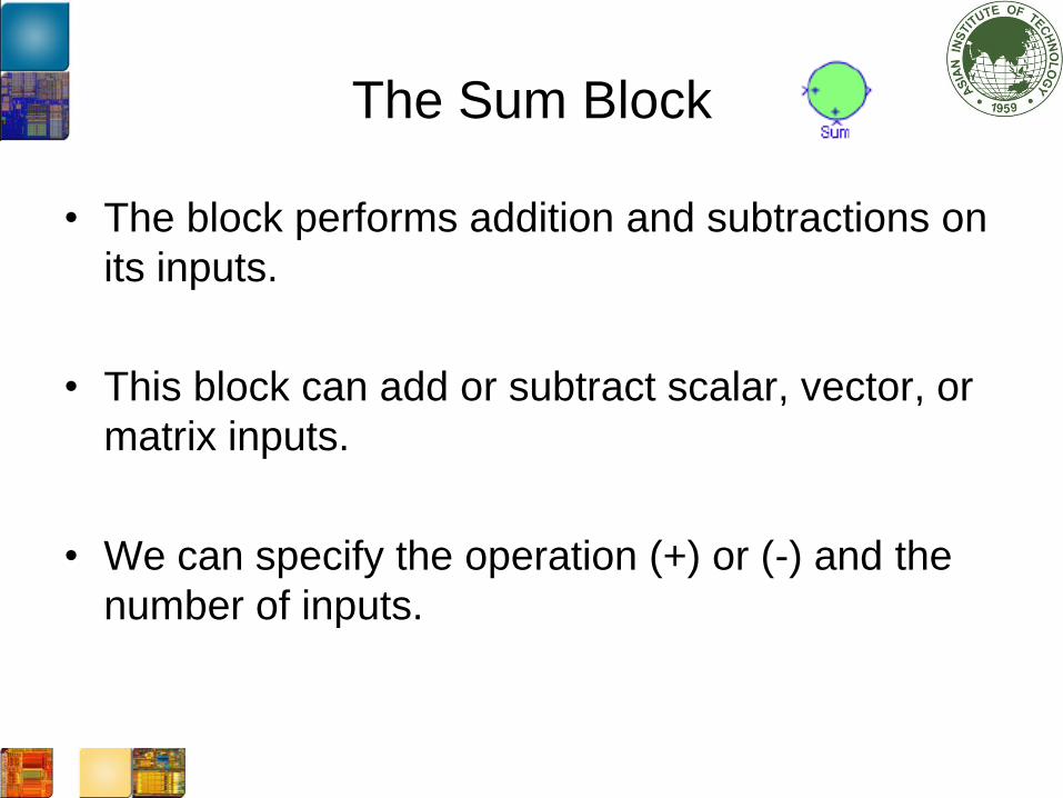
The Sum Block
• The block performs addition and subtractions on
its inputs.
• This block can add or subtract scalar, vector, or
matrix inputs.
• We can specify the operation (+) or (-) and the
number of inputs.

Example of the Sum Block
• Operation A + B - C
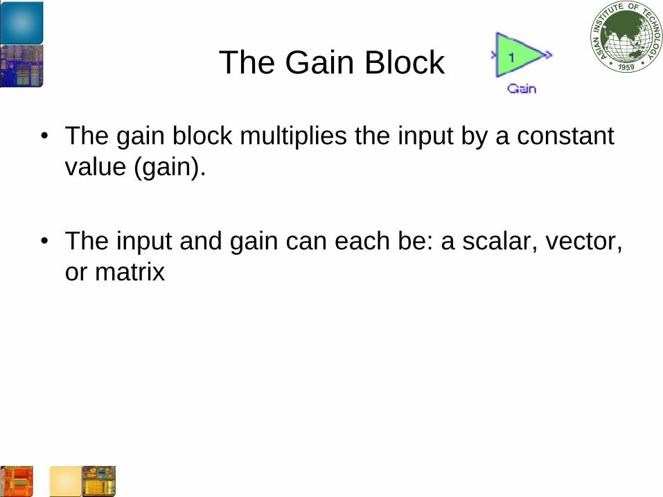
The Gain Block
• The gain block multiplies the input by a constant
value (gain).
• The input and gain can each be: a scalar, vector,
or matrix

The example of the gain block
• A = [1 -1 2], B = [2 3 4]

The Relational Operator Block
• The relational operator block performs the
specified comparison of its two inputs.
• The relation can be selected from the Relational
Operator paramters. Operation descriptions:
== True if the first input is equal to the second input
~= True if the first input is not equal to the second input
< True if the first input is less than the second input
<= True if the first input is less than or equal to the second input
>= True if the first input is greater than or equal to the second input
> True if the first input is greater than the second input
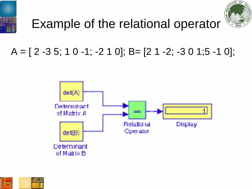
Example of the relational operator
A = [ 2 -3 5; 1 0 -1; -2 1 0]; B= [2 1 -2; -3 0 1;5 -1 0];
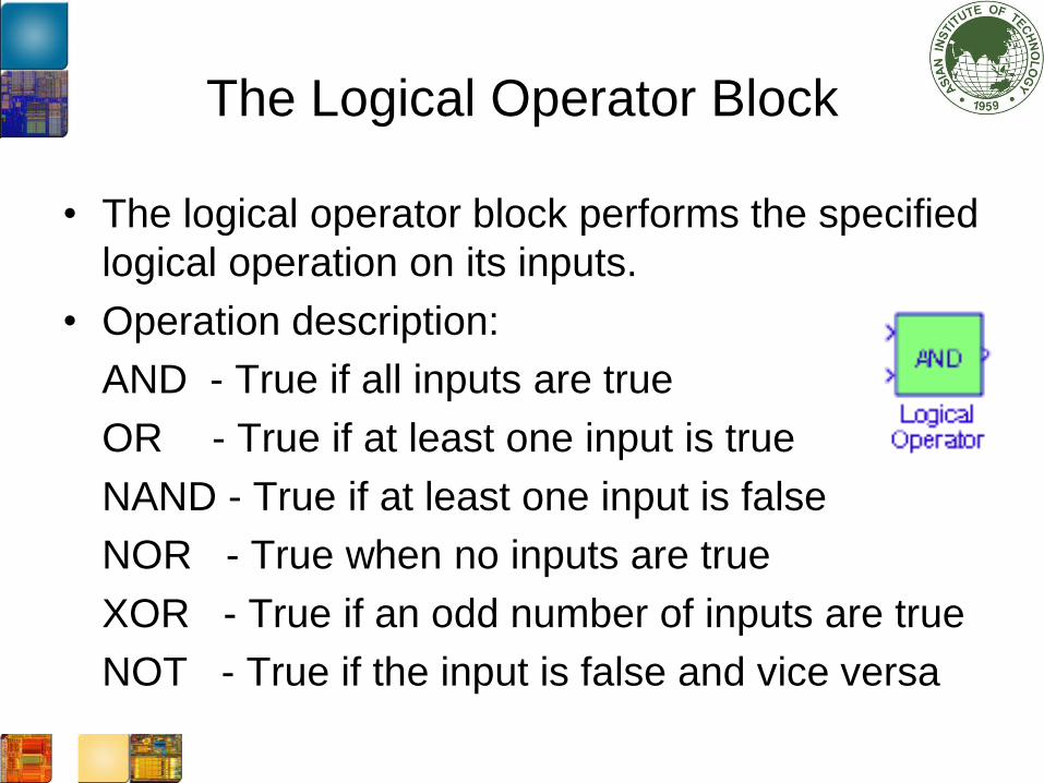
The Logical Operator Block
• The logical operator block performs the specified
logical operation on its inputs.
• Operation description:
AND - True if all inputs are true
OR - True if at least one input is true
NAND - True if at least one input is false
NOR - True when no inputs are true
XOR - True if an odd number of inputs are true
NOT - True if the input is false and vice versa
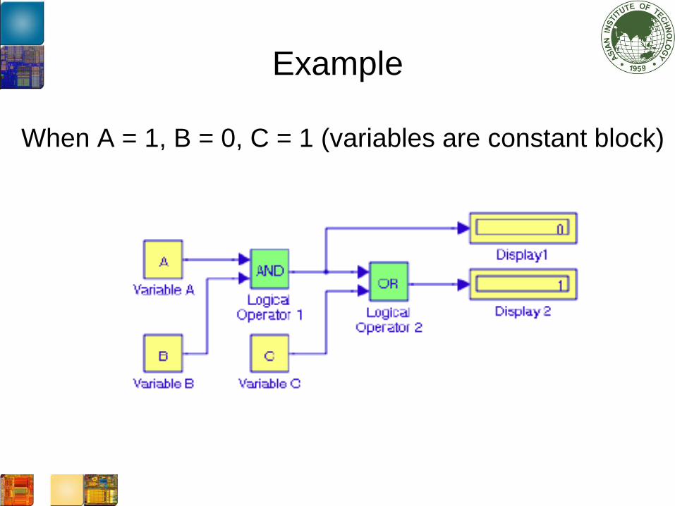
Example
When A = 1, B = 0, C = 1 (variables are constant block)

The Saturation Block
• The saturation block establishes the upper and
lower bound for an input signal.
• When the input signal is within the range
specified by the lower and upper limit, the input
signal passes unchanged.
• Otherwise, the input is clipped to upper or lower
bound.

An example
When x = 0: 1 : 6; y = 3. *x .^2;
The upper limit is set at 75 and lower limit is at 1.

The Integrator Block
• The Integrator block integrates its input and is
used with continuous-time signals.
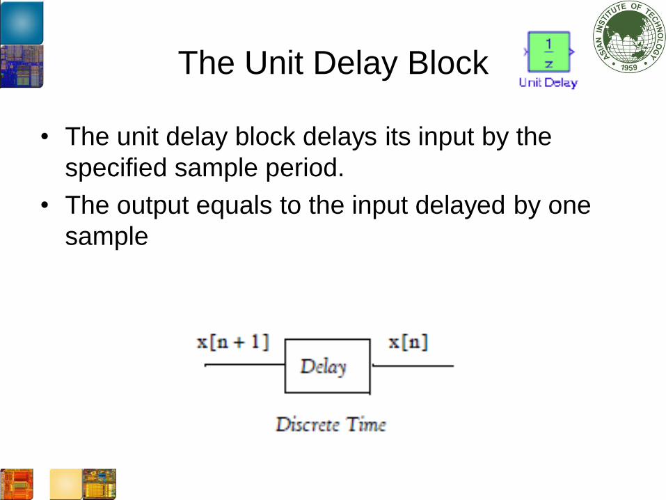
The Unit Delay Block
• The unit delay block delays its input by the
specified sample period.
• The output equals to the input delayed by one
sample

The Discrete Time Integrator Block
• The discrete time integrator block performs
discrete time integration or accumulation of a
signal.
• We use this block in discrete-time signal

An example of the model
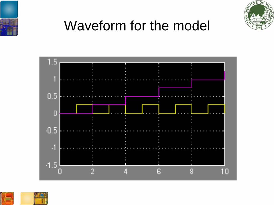
Waveform for the model

Data Type Conversion
• Built-in data types supported by Matlab

Data Type Conversion Block
• The data type conversion block converts an
input signal of any Simulink data type to the data
type and scaling specified by the block’s output
data type parameter
• Two possible data support:
- Real World Value (RWV)
- Stored Integer (SI)

Data types
• RWV treats the value as V = SQ + B where S is
the slope and B is the bias.
• SI treats the input as a stored integer. It will use
only the Q value.

An example of Data Type Conversion

Data Type Conversion 1

Output Data Type
• Output data type is set to fixdt(1,8,2^-3,0).
• It indicates that the output data are expressed in
fixed point.
• The first number indicates a sign number
• The second number is the word length
• The third number is slope
• The last number is the bias

Example
• The integer number 63 is represented by:
00111111 in binary.
• With the slope of 2^-3, it becomes 00111.111
whose value is 7.875
• Hence S = -3, Q = 00111.1112 and B = 0.

Data Type Conversion 2
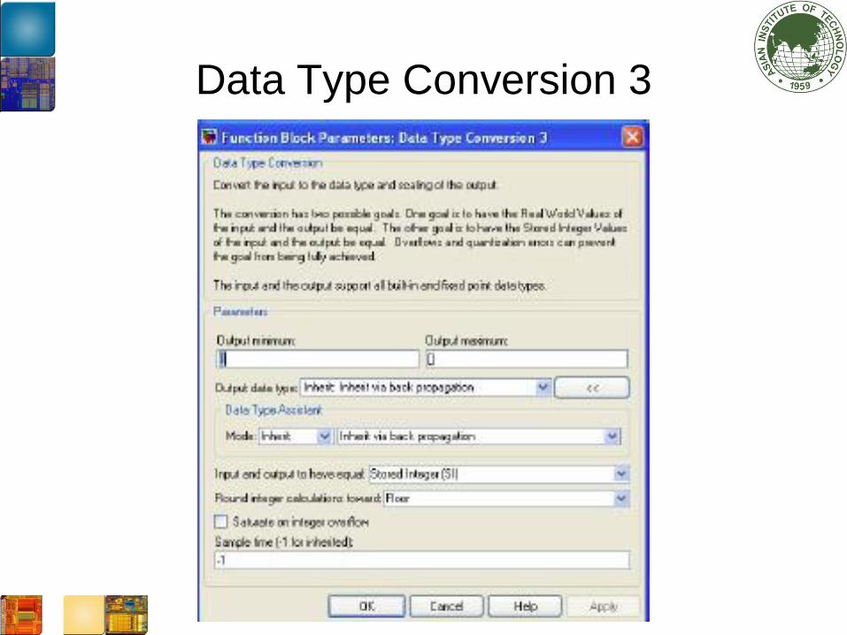
Data Type Conversion 3

Another example

Data Type Conversion 1

Data Type Conversion 2

Data Type Conversion 3

Question?