Simplified Interconnection Seminar - Eversource · Simplified Interconnection Seminar November 2,...
45
Safety First and Always Simplified Interconnection Seminar November 2, 2017 Eversource Energy Hadley, MA
Transcript of Simplified Interconnection Seminar - Eversource · Simplified Interconnection Seminar November 2,...

Safety First and Always
Simplified
Interconnection Seminar
November 2, 2017
Eversource Energy
Hadley, MA

Safety First and Always
Co-Hosts
Mass ACA

Safety First and Always
Logistics & Introductions
▪ Facilities
– Emergency exits
– Restrooms
– Designated smoking areas
▪ Introductions
– DOER / Mass CEC / Mass ACA
– MA Utilities
– Guests

Safety First and Always
Safety Moment
▪ Do not operate utility equipment.
▪ Overhead power lines are not insulated, and carry enough energy
to cause serious injury or even death. Regard all wires as live.
▪ Keep yourself, your co-workers, tools, ladders and vehicles at
least 10 feet away from electric lines and equipment.
▪ Make sure the area is clear of wires before working near trees or
shrubs.
▪ Never attach or tie anything off to power lines or electrical
equipment.
▪ If you need to dig, first call Dig Safe at 1-888-dig-safe (1-888-344-
7233) to get underground utilities marked. (www.digsafe.com)

Safety First and Always
Eversource Energy Seminars
December 13, 2017 Westwood
February 22, 2018 Hadley
May 9, 2018 Hadley
August 23, 2018 Hadley
November 7, 2018 Hadley
* Note: Additional seminars will be announced soon.

Safety First and Always
Eversource Website
▪ Please refer to www.eversource.com for interconnection and net
metering information.
▪ There are different sections for Eastern Massachusetts (EM DG)
and Western Massachusetts (WM DG).
– Eversource Energy – EM DG
▪ Email: [email protected]
– Eversource Energy – WM DG
▪ Email: [email protected]
Safety First and Always
New Requirements
7

Safety First and Always
Energy Storage
▪ Eversource is required to start tracking energy storage.
– Yearly reporting of energy storage information to the MA DPU starts in
December of 2017.
– Details for the tracking, reporting and data collection are in development.
– Submittal of the Energy Storage Supplemental Information form is requested.
The form may change.
▪ For new applications, submit the Energy Storage Supplemental
Information form with your interconnection application.
▪ For applications already in process, the form should be submitted
prior to approval to installation of a bi-directional meter and
approval to operate.
▪ For customers with existing storage, please fill out and submit the
form to Eversource as soon as possible.

Safety First and Always
Energy StorageEversource Energy
Interconnection Application Request
Energy Storage Supplemental Information Requirements
Energy Storage Configuration Check One
Utility Side
Customer Side choices
DC only not Grid Parallel
Grid Parallel - Non Export
Grid Parallel - Export
Energy Storage Customer Intended Use Check All that Apply
Demand Charge Reduction
Load Shifting
Renewables Firming/Ramp Rate Smoothing
Microgrid Islanding
Wholesale Market Participation
Other TEXT
Energy Storage Program Type Check All that Apply
MA - SMART Program
MA - Energy Efficiency Program
MA - DOER Storage Grant
MA - Section 83 (c ) or 83 (d)
Other TEXT
Energy Storage Technology Check One
Lithium Ion
Lead Acid
Sodium Chemistry
Vanadium Redox
Zinc Redox
Pumped Hydro
Compressed Air Energy Storage
Other Technologies TEXT
Energy Storage Manufacturer
TEXT
Energy Storage Model #
TEXT
Energy Storage Inverter Manufacturer, if applicable
TEXT
Energy Storage Inverter Model #, if applicable
TEXT
Energy Storage Capacity (DC) KW
numeric value (XXXXX.X)
Energy Storage ENERGY (DC) KWH
numeric value (XXXXX.X)
Energy Storage Capacity (AC) KW, if applicable
numeric value (XXXXX.X)
Energy Storage ENERGY (AC) KWH, if applicable
numeric value (XXXXX.X)
Energy Storage Export Capacity (AC) KW, if applicable
numeric value (XXXXX.X)

Safety First and Always
ISO-NE Ride Through Settings
▪ All inverters based applications received on or after January 1,
2018*, shall be:
– Certified per the requirements of UL1741-SA as a grid support utility
interactive inverter
– Have the voltage trip settings in Table I
– Have the frequency trip settings in Table II
* NOTE: This applies to applications received after 4:00 PM on Friday December 29, 2017.

Safety First and Always
ISO-NE Ride Through Settings
▪ All inverters based applications shall:
– Ride through per the requirements in UL1741-SA
– Have the voltage ride through capability set per Table III
Ride-Through
Voltage (%)Operating Mode Ride-Through
Time (seconds)
120≤V N/A No ride through
110≤V<120 Momentary
Cessation
2
88<V<110 Continuous
Operation
Infinite
50≤V≤88 Mandatory
Operation
1.9
V<50 Momentary
Cessation
1.0

Safety First and Always
ISO-NE Ride Through Settings
▪ All inverters based applications shall:
– Have the frequency ride through capability set per Table IV
Frequency range
(Hz)
Operating Mode Ride Through time(s)
f > 62.0 N/A N/A
60.6 ≤ f < 62.0 Mandatory
Operation a
299
58.5 < f < 60.6 Continuous
Operation
Infinite (c)
56.5 < f ≤ 58.5 Mandatory
Operation b
299
f ≤ 56.5 N/A N/A

Safety First and Always
ISO-NE Ride Through Settings
▪ All inverters based applications shall have:
– Other functions required by UL1741-SA shall comply with the requirements
specified in Table VFunction Status Default Settings
Anti-Islanding ON ONLow / High Voltage Ride-Through ON Per Table III Above.
Low/High Frequency Ride-Through ON Per Table IV Above
SPF, Specified Power Factor (fixed power
factor)ON Unity p.f
Q(V), Volt-Var Function with Watt or Var
Priority (Also known as Dynamic Volt/VAR
operations)
OFF OFF
Soft Start ON Upon starting to inject power
into the grid, following a period
of inactivity or a disconnection,
the inverter shall be able to
control its rate of increase of
power from 1% to 100%
maximum current per second,
with specific settings as
mutually agreed upon by the
Distribution Provider and the
Producer. FW, Freq-Watt Function OFF OFF OFF
[1] Unless otherwise required by the utility.[2] Per existing utility interconnection requirements.

Safety First and Always
DG Tariff Overview
And General Information
14

Safety First and Always
Interconnection Process
▪ Seminar concerns Standards for Interconnecting Distributed Generation, the current tariff approved by the DPU in 2015.
▪ Process of getting an interconnection agreement from your local electric distribution company to connect a distributed generation system to their distribution system.
▪ This process is used by the four investor owned utilities (IOU) in Massachusetts (WMECO d/b/a Eversource Energy, NSTAR d/b/a Eversource Energy, National Grid, Unitil).
▪ Municipally owned utilities are not required to follow this process and may follow a different process.
▪ The process is used to make sure interconnecting DG systems are integrated into the distribution system responsibly with respect to impacts on reliability, power quality and safety.
▪ Everything officially starts with the Simplified application.
15

Safety First and Always
DG Tariff Overview
▪ Introduction and Definitions – Section 1
▪ Process Overview – Section 3
▪ Operating Requirements - Section 6: Interconnecting Customer must operate system safely and to ensure no adverse affects or interference to other customers
▪ Disconnection – Section 7: Covers planned and unplanned outages
▪ Metering, Monitoring, and Communication – Section 8: Covers requirements for metering the account the generation is interconnected with
▪ Dispute Resolution Process – Section 9
▪ Confidentiality Statement – Section 10
▪ Insurance Requirements – Section 11
▪ Exhibits – shows all pro forma applications, agreements, terms and conditions, and Schedule Z
16

Safety First and Always
DG Tariff – Section 2
If you don’t read any other portion of the standard – at least read this.
▪ Interconnecting Customer / Customer / Landowner and Company must enter into an agreement to interconnect generation.
▪ Consult with the Company before design to determine what utility facilities are present. *** A Pre-Application Report Form (PAR) is optional for projects under 500 kW. ***
– Company can supply general circuit information for the proposed location; voltage, radial/network, three phase/single phase.
– Keep in mind that the distribution system can change and other applications submitted between when a PAR is prepared and when you submit the interconnection application.
– For RFP’s – Customer can consult utility prior to going out for bid, questions should be directed to customer for submittal to utility. Bidders should not contact utility for site specific information.
17

Safety First and Always
DG Tariff – Section 4
▪ Interconnection Requirements
▪ 4.1 Interconnecting Customer will ensure its Facility meets or exceeds requirements including:
– Transient Voltage Conditions
– Noise and Harmonics
– Frequency
– Voltage Level
– Machine Reactive Capability
▪ 4.2 Protection Requirements for New or Modified Facility Interconnections with the EPS. Covered in extensive detail. Someone on Interconnecting Customer’s team needs to understand and be responsible for meeting these requirements.
– NPCC under frequency settings; 57Hz in 0.16 seconds and 58 Hz in 32 seconds for DG 30 kW and larger.
– Phase loss relay required for three phase generation facility using single phase inverters.
▪ As size of DG increases and more DG is added to circuits, more studies are required, even for smaller DG.
▪ There is an interconnection queue and applications are processed in order received on the circuit and/or substation.
18

Safety First and Always
DG Tariff – Section 5
▪ Responsibility for Costs
▪ Interconnecting Customer responsible for:
– Costs of the review by the Company and any interconnection studies conducted. (Application Fee, Supplemental Review, Witness Test (in extenuating circumstances))
– All costs associated with the installation and construction of the Facility and associated interconnection equipment on the Interconnecting Customer’s side of the PCC.
– All costs incurred by Company to design, construct, operate and maintain the System Modifications. Can include ongoing charges.
o Costs for new services, service upgrades, service relocations, etc.
o Equipment required by ISO-NE (telemetry, etc.)
o Construction costs including CIAC tax liability.
19

Safety First and Always
Third Party, Land Ownership and
Important Definitions
▪ Tariff allows for third party ownership of generation
▪ Application must include information for both generation owner (Interconnecting
Customer) and electric customer (Customer)
▪ Provide information on owner of property/land (Landowner) if not the electric
customer or owner of generation.
▪ Utility (Company) will correspond with owner, customer and installer
– Listing names, phone numbers and email addresses for all parties on
application makes communication easier and faster
▪ Utility will enter into agreement with our electric customer (Exhibit H of tariff)
▪ Utility will enter into an agreement with the owner (Exhibit I of tariff) of the
property/land if the Interconnecting Customer and Customer are not the
Landowner.
20

Safety First and Always
Before You Start……..
▪ Read the DG Tariff.
▪ Identify the Interconnecting Customer – owner of the generation.
▪ Identify the Customer – primary account holder listed on the
electric account.
▪ Identify the Landowner.
▪ If the name, address, landlord information is not correct on the
electric account, work with our Customer Service Department to
correct it.
▪ Identify property lines and include on your site plan.
▪ Identify all generation and storage on the property. Include all
generators on the one line and site plan. Transition switches must
be labeled open or closed. Existing closed transition
generators and storage without an existing ISA must be
studied and included in the new ISA.21

Safety First and Always
Before You Start……..
▪ Contact your local utility prior to designing any changes to an existing generation facility.
▪ If you want to replace an inverter, increase the output of your facility or install storage, submit a new interconnection application.
▪ Be clear on application, site plan and electrical sketch as to what equipment is existing, what equipment is new and what equipment (if any) is being replaced. Make additional notes or provide additional documentation if necessary.
▪ If you are installing a new service or making changes to your existing service, provide the WR # on the interconnection application. That work will likely need to be completed before the DG application can be reviewed or completed.o Also, for Simplified applications, the service work and regular meter will need
to be installed and the account established before a net meter can be ordered.
▪ When System Modifications are required for a Simplified Application, the construction must be completed before approval to install is granted.
22

Safety First and Always
Application Fees
23
Application Fee is based on aggregate maximum kW AC size of project.

Safety First and Always
Simplified
Interconnection Information
24

Safety First and Always
Simplified Application
▪ APPLIES TO:
– Single phase listed single-phase inverter based systems 15.0 KW or less on single phase service on radial feed.
– Three phase listed three-phase inverter based systems 25.0 KW or less on three phase service on radial feed. Single phase inverters on a three phase service DO NOT QUALIFY for Simplified Process interconnection
– Size is based on aggregate maximum AC kW output of inverters, including storage.
– A listed inverter means:
– Complies with current IEEE Standard 1547 and utility’s technical standard. MA has adopted UL 1741.1 as the standard for inverters to comply with IEEE 1547.
– Nationally recognized test lab results.
▪ Project should be fully designed with exact make, model and number of Listed inverters which will be installed.
25

Safety First and Always
Simplified Spot and Area Network
Application▪ APPLIES TO:
– Simplified Spot Network Process: listed inverter based system 1/15th
of electric customer’s MINIMUM load.
– Simplified Area Network Process: listed inverter based system 15.0 kW or less and 1/15th of electric customer’s MINIMUM load.
– A study should be expected to determine minimum load.
– If your project does not meet these requirements, you will need to submit a Standard Application.
– Size is based on aggregate maximum AC output of inverters, including storage.
– A listed inverter means:
– Complies with current IEEE Standard 1547 and utility’s technical standard. MA has adopted UL 1741.1 as the standard for inverters to comply with IEEE 1547.
– Nationally recognized test lab results.
26

Safety First and Always
Simplified Spot and Area Network
Application
▪ Additional Technical Requirements:
– Must interconnect with a breaker in the customer’s panel. Line side taps are not permitted.
– Revenue meter must be self contained or cold sequenced and located outside.
– AC Disconnect switch must be located within 10 feet and in visible site of the revenue meter and located on same wall of building.
27

Safety First and Always
Simplified Process
Changes and upgrades to existing interconnections:
▪ Contact your local utility prior to designing any changes to an existing generation facility.
▪ If you want to replace an inverter, increase the output of your facility, install a closed transition generator, or add storage, submit a new interconnection application unless you are replacing the inverter with the same exact make, model and size inverter. Contact the Company to verify this.
▪ Be clear on the application, electrical sketch and site plan as to what equipment is existing, what equipment is new and what equipment is being replaced.
▪ Make additional notes or provide additional documentation if necessary.
28

Safety First and Always
Everything starts with application
▪ A complete application includes:– All appropriate sections of Simplified application completely filled out and
SIGNED by the Interconnecting Customer. Customer will likely need assistance from vendor/engineer. Signature must be a wet signature. Docusign is not accepted.
– Electrical Sketch
– Site Plan / Drawing
– Inverter cut sheet
– UL 1741 certification (if not already on file)
– Work Request number if there is a new service or there is a service upgrade
– If necessary, identify ownership of property and provide proof of site control if Customer and/or Interconnecting Customer does not own the property.
– Application fee of $100 or $300 for Spot and Area Networks.
– Identify electric utility customer and owner of proposed generation
– Schedule Z if planning to be compensated under Net Metering Tariff
– If necessary, identify ownership of property and provide proof of site control if Customer and/or Interconnecting Customer does not own the property.
▪ Errors or problems with application will slow down the process and “stop the clock”
▪ Send Electronic copy of all documents if possible – Easier to distribute, saves paper and is faster.
29

30
Contact Information: Date Prepared: _________________
Legal Name and address of Interconnecting Customer
Interconnecting Customer (print): ____________________Contact Person: ________________
Mailing Address: _______________________________________________________________
City: ________________________________State: ________________ Zip Code: __________
Telephone (Daytime): __________________ (Evening): ________________________________
Facsimile Number: ____________________ E-Mail Address: ___________________________
Customer name (if Customer is not Interconnecting Customer) ___________________________
Customer email: ___________________________ Customer telephone: ___________________
Customer Mailing Address: _______________________________________________________
City: ________________________________State: ________________ Zip Code: __________
Landowner name (if neither Interconnecting Customer nor Customer)
___________________________
Landowner email: _________________________Landowner telephone: ___________________
Landowner Mailing Address:
______________________________________________________
City: ________________________________State: ________________ Zip Code: __________
Alternative Contact Information
(e.g., system installation contractor or coordinating company, if appropriate):
Name: ________________________________________________________________________
Mailing Address: _______________________________________________________________
City: ________________________________State: ________________ Zip Code: __________
Telephone (Daytime): __________________ (Evening): ________________________________
Facsimile Number: ____________________ E-Mail Address: ___________________________
Electrical Contractor Contact Information (if appropriate):
Name: ___________________________________ Telephone: __________________________
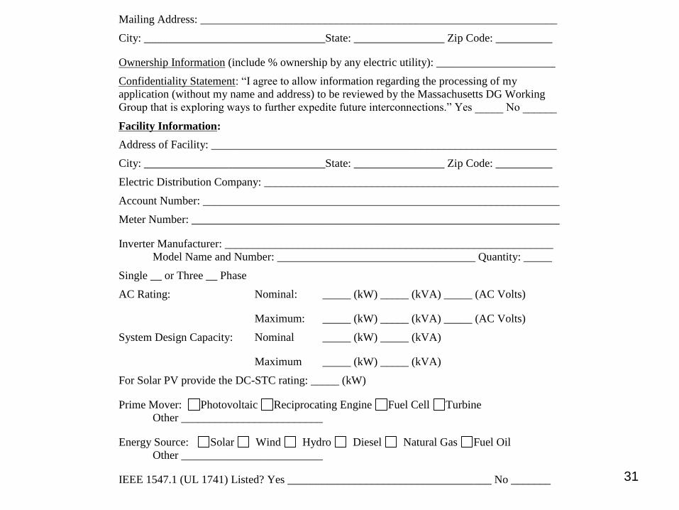
31
Mailing Address: _______________________________________________________________
City: ________________________________State: ________________ Zip Code: __________
Ownership Information (include % ownership by any electric utility): _____________________
Confidentiality Statement: “I agree to allow information regarding the processing of my
application (without my name and address) to be reviewed by the Massachusetts DG Working
Group that is exploring ways to further expedite future interconnections.” Yes _____ No ______
Facility Information:
Address of Facility: _____________________________________________________________
City: ________________________________State: ________________ Zip Code: __________
Electric Distribution Company: ____________________________________________________
Account Number: _______________________________________________________________
Meter Number: _________________________________________________________________
Inverter Manufacturer: __________________________________________________________
Model Name and Number: ___________________________________ Quantity: _____
Single __ or Three __ Phase
AC Rating: Nominal: _____ (kW) _____ (kVA) _____ (AC Volts)
Maximum: _____ (kW) _____ (kVA) _____ (AC Volts)
System Design Capacity: Nominal _____ (kW) _____ (kVA)
Maximum _____ (kW) _____ (kVA)
For Solar PV provide the DC-STC rating: _____ (kW)
Prime Mover: Photovoltaic Reciprocating Engine Fuel Cell Turbine
Other _________________________
Energy Source: Solar Wind Hydro Diesel Natural Gas Fuel Oil
Other _________________________
IEEE 1547.1 (UL 1741) Listed? Yes ____________________________________ No _______
32
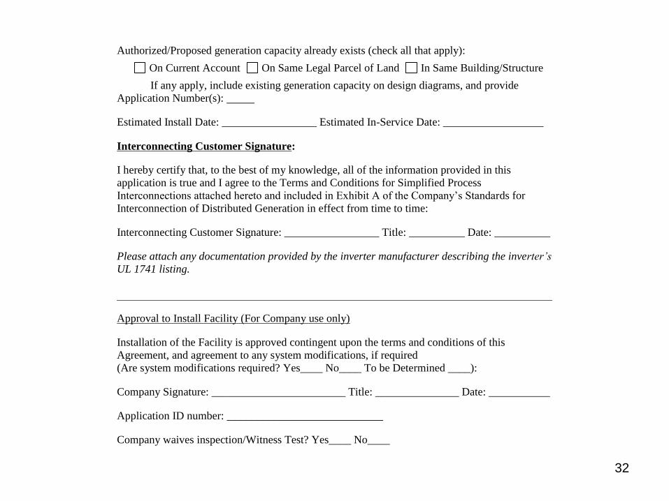
Authorized/Proposed generation capacity already exists (check all that apply):
On Current Account On Same Legal Parcel of Land In Same Building/Structure
If any apply, include existing generation capacity on design diagrams, and provide
Application Number(s):
Estimated Install Date: _________________ Estimated In-Service Date: __________________
Interconnecting Customer Signature:
I hereby certify that, to the best of my knowledge, all of the information provided in this
application is true and I agree to the Terms and Conditions for Simplified Process
Interconnections attached hereto and included in Exhibit A of the Company’s Standards for
Interconnection of Distributed Generation in effect from time to time:
Interconnecting Customer Signature: _________________ Title: __________ Date: __________
Please attach any documentation provided by the inverter manufacturer describing the inverter’s
UL 1741 listing.
Approval to Install Facility (For Company use only)
Installation of the Facility is approved contingent upon the terms and conditions of this
Agreement, and agreement to any system modifications, if required
(Are system modifications required? Yes____ No____ To be Determined ____):
Company Signature: ________________________ Title: _______________ Date: ___________
Application ID number: ____________________________
Company waives inspection/Witness Test? Yes____ No____

Safety First and Always
Simplified Requirements
Submit an electrical sketch with application:
▪ DOES NOT need to be stamped by a MA PE.
▪ Must show the existing/proposed service, including the revenue metering, and how/where the proposed generation will interconnect to it.
▪ Can be hand drawn but must be legible.
▪ Clearly label any transfer switches “open transition” or “closed transition”.
▪ Must show actual proposed equipment. Ex: Do NOT include “MIN 60A” for a disconnect size.
▪ Inverter settings.
▪ SHOULD NOT specify equipment TBD by Company.
▪ If you submit a revised electrical sketch, please include a date and/or revision number on the sketch.
33

Safety First and Always
Simplified Requirements
Submit an electrical sketch with application:
▪ Include the following on the sketch:
– Size of main breaker (100 Amp, 200 Amp, 400 Amp, etc.)
– Voltage of service (120/240 V, 120/208 V, etc.)
– Service configuration (single phase 1PH 3W, three phase 3PH 4W)
– Size of external AC disconnect switch (60 Amp non-fused, 60 Amp fused, etc.)
– Customer name
– Address of facility
– Number and make/model of inverter(s)
– Any existing and back up generation (if applicable)
– Any transfer switches must be clearly labeled open transition or closed transition
– Any inverters and batteries for storage (if applicable)
34

Safety First and Always
35
Example Electrical Sketch
Electrical Sketch
Example Customer
0 Example St
Nowhere, MA 01234
1PH, 3W
Safety First and Always
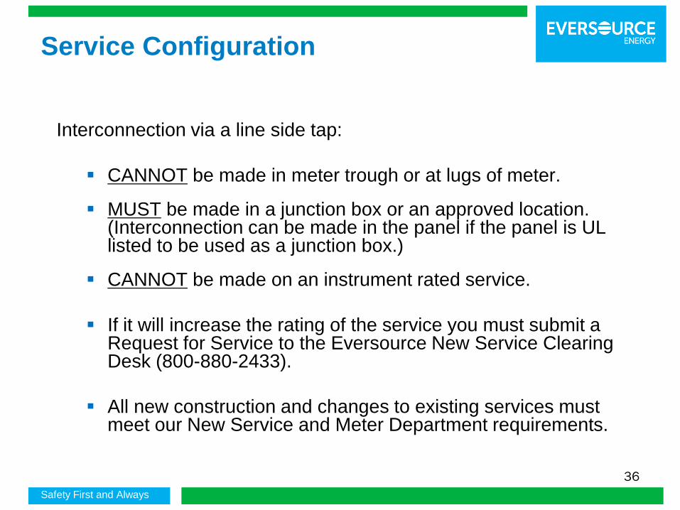
Service Configuration
Interconnection via a line side tap:
▪ CANNOT be made in meter trough or at lugs of meter.
▪ MUST be made in a junction box or an approved location. (Interconnection can be made in the panel if the panel is UL listed to be used as a junction box.)
▪ CANNOT be made on an instrument rated service.
▪ If it will increase the rating of the service you must submit a Request for Service to the Eversource New Service Clearing Desk (800-880-2433).
▪ All new construction and changes to existing services must meet our New Service and Meter Department requirements.
36

Safety First and Always
Service Configuration
Line side tap will NOT require a service upgrade (self contained meter only) if rating of tap is less than existing service size fed from a radial feed and:
▪ A load center will not be installed beyond the tap.
▪ Any load center installed beyond the tap will ONLY contain generation circuits and will contain NO LOADS and NO OPEN POSITIONS
• This type of design must be clearly specified on the electrical sketch
• Photos clearly showing the load center(s) must be included as part of the completion photos.
• A system which is granted Approval to Install based on the preceding conditions, but then is installed such that an upgrade is required WILL NOT be given Approval to Operate until the system is installed as designed or the upgrade is completed.
Line side tap WILL REQUIRE a Service upgrade (i.e. 100 A to 200 A or 200 A to 400 A) (self contained meter only fed from a radial feed) if:
▪ A load center is installed beyond the line side tap which contains load circuits or open positions in addition to generation circuits.
• The application will be considered on hold for New Service, and Approval to Operate will NOT be granted until the modifications are completed.
• All of Eversource’s New Service requirements must be met.
▪ Tap exceeds rating of existing service.
37

Safety First and Always
Site Plan
Submit a site plan with application:
▪ Must show revenue meter location and location of inverter(s) and all existing generation.
▪ Must show AC generator disconnects.
▪ Can be hand drawn but must be legible.
▪ Does not need to be PE Stamped.
▪ Must be a plan form view i.e. vertical NOT “bird’s eye”, isometric, 3/4 view.
▪ Include Customer name and address of facility.
▪ Must show parcel boundaries (property/lot lines and other generation.
▪ If you submit a revised site plan, please include a date and/or revision number on the plan.
38

Safety First and Always
39
Example Site Plan
Site Plan
Example Customer
0 Example St
Nowhere, MA 01234

Safety First and Always
Technical Issues – Metering,
Disconnection
▪ Generator must be installed behind a utility revenue meter
▪ Can not interconnect in meter socket/meter trough
▪ Cold sequence metering required for instrument rated services and all 277/480 V services.
▪ Approved disconnect means must be provided to isolate metering instrument transformers
▪ AC disconnect switch with visible break must be located outside and within 10 feet and visible sight of revenue meter.
▪ Disconnect switches are required for all generation facilities.
40

Safety First and Always
Supplemental Review
▪ If additional time is required to review your application for technical reasons, the application will be designated Simplified + 5 Days
▪ If one or more Screens are not passed or if additional time is needed to determine system modifications or technical review, the Company will provide a Supplemental Review Agreement.
▪ Interconnecting Customer signs agreement and pays fee for additional engineering time (max fee is $4,500).
▪ The Supplemental Review may be able to determine what impacts the generation system will have and what (if any) modifications are required. If so - an interconnection agreement will be sent to customer detailing:
– System modification requirements, reasoning, and costs for these modifications
– Specifics on protection requirements as necessary
▪ If Supplemental Review cannot determine requirements, Impact Study Agreement (or equal) will be sent to the customer. (Project shifts to the Expedited/Standard Process.)
41
Safety First and Always
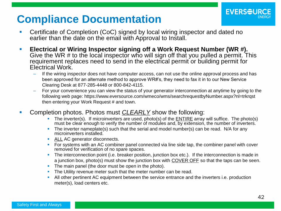
Compliance Documentation▪ Certificate of Completion (CoC) signed by local wiring inspector and dated no
earlier than the date on the email with Approval to Install.
▪ Electrical or Wiring Inspector signing off a Work Request Number (WR #). Give the WR # to the local inspector who will sign off that you pulled a permit. This requirement replaces need to send in the electrical permit or building permit for Electrical Work.
– If the wiring inspector does not have computer access, can not use the online approval process and has
been approved for an alternate method to approve WR#’s, they need to fax it in to our New Service
Clearing Desk at 877-285-4448 or 800-842-4115.
– For your convenience you can view the status of your generator interconnection at anytime by going to the
following web page: https://www.eversource.com/wmeco/wms/searchrequestbyNumber.aspx?nl=trkrqst
then entering your Work Request # and town.
▪ Completion photos. Photos must CLEARLY show the following:▪ The inverter(s). If microinverters are used, photo(s) of the ENTIRE array will suffice. The photo(s)
must be clear enough to verify the number of modules and, by extension, the number of inverters.
▪ The inverter nameplate(s) such that the serial and model number(s) can be read. N/A for any microinverters installed.
▪ ALL AC generator disconnects.
▪ For systems with an AC combiner panel connected via line side tap, the combiner panel with cover removed for verification of no spare spaces.
▪ The interconnection point (i.e. breaker position, junction box etc.). If the interconnection is made in
a junction box, photo(s) must show the junction box with COVER OFF so that the taps can be seen.
▪ The main panel (the door must be open in the photo).
▪ The Utility revenue meter such that the meter number can be read.
▪ All other pertinent AC equipment between the service entrance and the inverters i.e. production
meter(s), load centers etc.
42

Safety First and Always
Compliance Documentation
▪ A Witness Test may be required:
– A Witness Test WILL be required for ALL battery backup and storage systems.– If the system is a battery backup or storage system or uses microinverters the Interconnecting Customer
/ Installer must ensure that there is a means to clearly show instantaneously when the system is and is not exporting power.
– If so, provide a Witness Test Procedure.
▪ Signed Customer Agreement (Exhibit H) and/or Landowner Agreement (Exhibit I), when required.
▪ If net metered, Schedule Z.
▪ If net metered, a RESERVED cap allocation from the Mass ACA for systems over 10.0 kW AC nominal on a single phase service or over 25 kW AC nominal on a three phase service.
▪ System must be installed as specified on the application and designed on electrical sketch and site plan.
43

Safety First and Always
Simplified Process Tips
▪ Submit application to correct Eversource office well in advance of when you plan to start construction.
▪ Provide the WR # to the Electrical or Wiring Inspector.
▪ If you are installing a new service or making a change to your existing service, that work must be complete before your Simplified Application can be approved for installation.
▪ If making any changes to the electric service, notify DG Team and provide WR#. Service changes and System Modifications must be completed before approval to install is granted for Simplified applications.
▪ Obtain a Reserved cap allocation if required for Net Metering.
▪ Submit all compliance documents by December 1, 2017 to allow for review and the scheduling of the installation of the revenue meter.
▪ Tariff allows 12 months for installation after approval to install is granted.
44
Safety First and Always
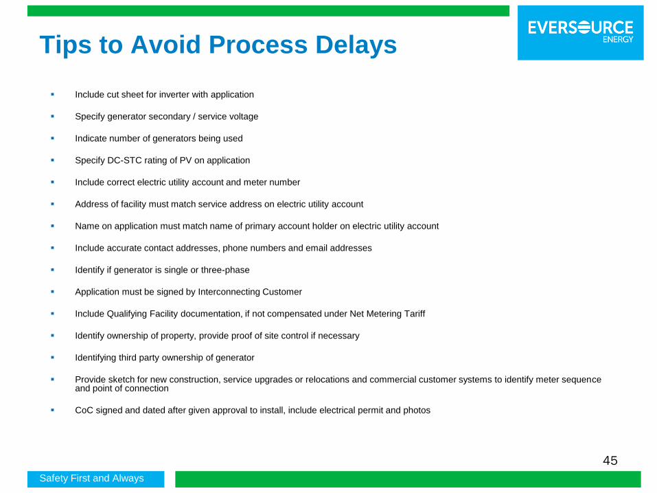
Tips to Avoid Process Delays
▪ Include cut sheet for inverter with application
▪ Specify generator secondary / service voltage
▪ Indicate number of generators being used
▪ Specify DC-STC rating of PV on application
▪ Include correct electric utility account and meter number
▪ Address of facility must match service address on electric utility account
▪ Name on application must match name of primary account holder on electric utility account
▪ Include accurate contact addresses, phone numbers and email addresses
▪ Identify if generator is single or three-phase
▪ Application must be signed by Interconnecting Customer
▪ Include Qualifying Facility documentation, if not compensated under Net Metering Tariff
▪ Identify ownership of property, provide proof of site control if necessary
▪ Identifying third party ownership of generator
▪ Provide sketch for new construction, service upgrades or relocations and commercial customer systems to identify meter sequence and point of connection
▪ CoC signed and dated after given approval to install, include electrical permit and photos
45