Simplified Electric Operating System - cdn.ymaws.com · Recloser opens and then recloses thus...
62
Transcript of Simplified Electric Operating System - cdn.ymaws.com · Recloser opens and then recloses thus...

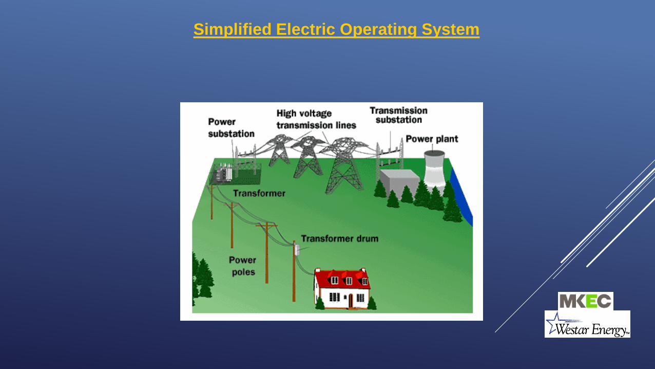
Simplified Electric Operating System

Simplified Electric Operating System
Generation

Simplified Electric Operating System
Generation
Transmission

Simplified Electric Operating System
Generation
Transmission
Distribution

Substations

Substations

Substations
115/12.47kV22.4MVA
Transformer

Substations
115/12.47kV22.4MVA
Transformer
115kV Bus

Substations
115/12.47kV22.4MVA
Transformer
12.47kV Bus 115kV Bus

Substations
12.47kV Breakers
115/12.47kV22.4MVA
Transformer
12.47kV Bus 115kV Bus

Substations12.47kV Breakers

Substations115kV Bus and 115/12.47kV 10.5MVA Xfmr

Substations115kV Bus and 115/12.47kV 10.5MVA Xfmr
115kV Fuses

Substations115kV Bus and 115/12.47kV 10.5MVA Xfmr
115kV Fuses 115kV Circuit Switcher

Power Flow Through Westgate Substation
34.5 kV Power Enters Station From Transmission Line
34.5 kV Power Flows Through Disconnect Switch
and FusesPower Flows Through Transformer
Voltage is Transformed from 34.5 kV to 12 kV
12 kV Power Flows Through Disconnect
Switch and Into 12 kV Bus
Power Flows Through 12 kV Breakers, Exits the Station Underground, and Runs to a Pole
Riser Where it is Tied to Overhead Lines
Power is Distributed to Our Customers

115 kV Power Enters Station from Transmission Line
Power Flows Through 115 kV Bus
Power Flows Through115 kV Circuit Breaker
Power Flows Through 115 kV Busand Circuit Switcher
Power Flows Through TransformerVoltage is Transformed from
115 kV to 12 kV
12 kV Power Flows ThroughCables Underground to Metal
Clad Switchgear
Power Flows Through 12 kV Breakers in Switchgear, Exits
the Station Underground, Runs to a Pole Riser Where it is Tied to
Overhead Distribution Lines
Power is Distributed to Our Customers
Power Flow Through 4th and Van Buren Substation

Distribution System

Distribution System
•The purpose of the Distribution System is to reduce Transmission System voltages to lower usable levels and to locally transport power from the substations to each individual customer.
•Lower voltages allow for a more cost effective means of locally transporting electrical power to individual customers
(ie lower voltage=smaller equipment=lower installed costs)
•Typical Distribution primary operating levels include:
- 34.5kV (sub-transmission)- 12.47kV- 7.2kV- 4.16kV- 2.4kV
•Westar operates and maintains approximately 27,000 miles of distribution lines serving approximately 659,000 customers.

Typical Distribution Line Equipment

Overhead (Pole-Mount) Underground (Pad-Mount)
Distribution Equipment- Transformers

•Transformers are used to reduce primary line voltage levels (typically 12.47kV-3ph, 7.2kV 1ph) down to a usable level by the customer (480V, 240V, 208V, 120V)
•Transformers consist of “primary” windings (high voltage) and “secondary” windings (low voltage) wound around a common core that are linked by electromagnetic fields. The amount of voltage reduction is directly related to the “turns ratio” between the windings.
•Transformers are rated to handle a certain amount of power expressed in “KVA”. The power limitation insures transformer thermal limits are not exceeded which could otherwise create a reduction in life.
•Single phase transformers consist of one primary and one secondary winding.
•Three phase transformers consist of three primary and three secondary windings.
•Single phase overhead transformers are routinely wired together to form three phase transformer banks. In general, summation of the three individual transformer sizes yields the equivalent 3 phase rating (excluding open-wye/open-delta banks).
Distribution Equipment- Transformers

Distribution EquipmentTypical Overhead Transformer Installations
Single Phase25KVA Xfmr
Three Phase500KVA Xfmr

Closed Open
Distribution Equipment- Fused Cut-Outs

•“Cut-Outs” are actually fuse holders which function normally as passive devices in that they simply conduct electricity to the load.
•On the event of a short-circuit condition downstream of the cut-out, a high amount of current instantaneously flows through the fuse element which in turn generates heat. After a given amount of time the fuse element melts out allowing the “barrel” to drop out of the cut-out thus interrupting power to the faulted section of line.
•This disruption of power to the faulted line segment is called sectionalizing and allows customers upstream of the cut-out to retain their electricity once the cut-out has opened.
•Fuses are sized to coordinate with the next upstream protective device to insure the proper sequence of sectionalizing occurs on the occurrence of a fault.
•Fuse elements are a one-time device and once they have melted, the fuse elements must be replaced.
•Cut-outs are used to protect the main feeders by installing them at each “tap” to increase reliability to other customers on the circuit. Cut-outs are also used on capacitor banks and transformers to isolate faulted equipment.
Distribution Equipment- Cut-Outs
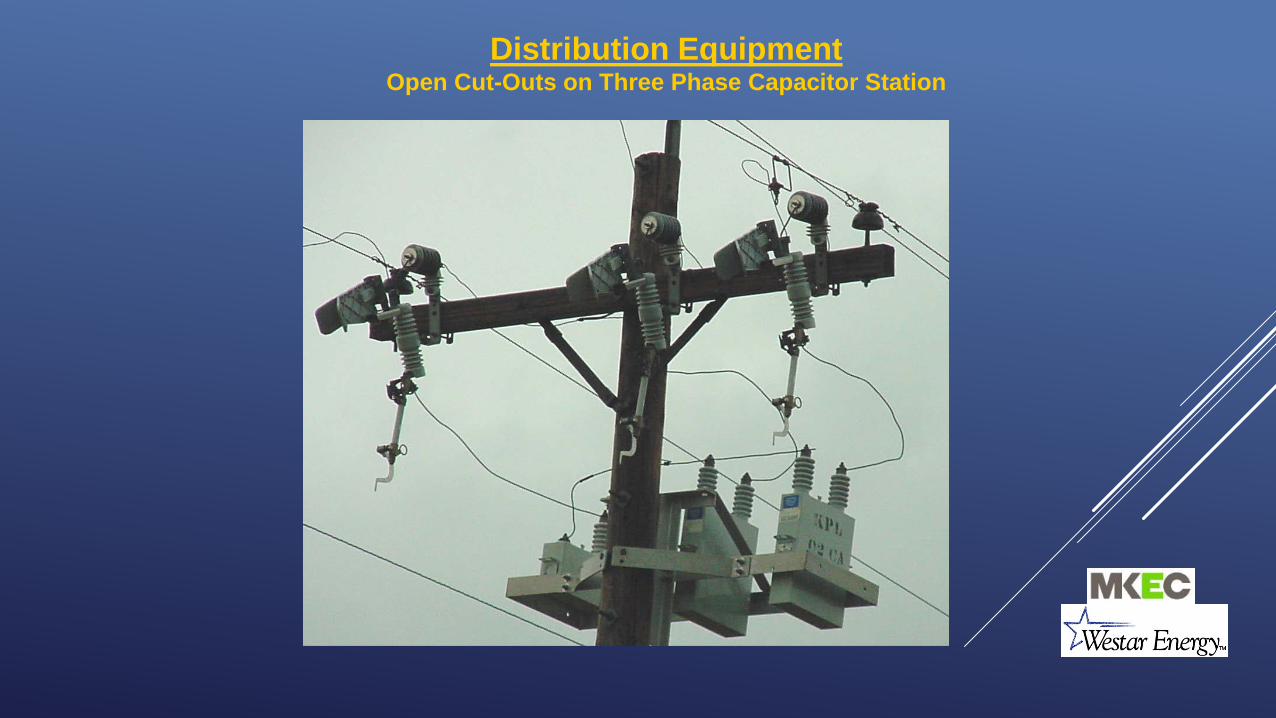
Distribution EquipmentOpen Cut-Outs on Three Phase Capacitor Station

Distribution Equipment- Hydraulic Reclosers
Three PhaseSingle Phase

Distribution Equipment- Hydraulic Reclosers•Reclosers are similar to a circuit breaker in that they open under unusually high amounts of electrical current (i.e. faulted condition).
•Reclosers normally act as passive devices in that they simply conduct electricity to the load.
•On the event of a short-circuit condition downstream of the recloser, a high amount of current instantaneously flows through the recloser. After a predefined amount of time the recloser will open and then, as the name implies, reclose thus momentarily interrupting power to the faulted section of line. This “reclosing” action allows for temporary faults to clear and then reestablishes power flow to the momentarily disrupted customers thus reducing/eliminating sustained outages.
•For permanent faults, the recloser will go through a series of open-close cycles before finally opening permanently. This is termed “going to a lock-out condition”. The faulted section of line must then be cleared and the recloser must be manually reset/closed.
•Reclosers are sized to coordinate with downstream fuses and upstream protective devices to insure the proper sequence of sectionalizing occurs on the occurrence of a fault.
•Timing is achieved through a mechanical “hydraulic” action of oil flowing through orifices, thus the term “Hydraulic Reclosers”.

Distribution Equipment- Hydraulic ReclosersTypical Field Installation

Distribution Equipment- Electronic Reclosers
Three Phase Vacuum Recloser Electronic Recloser Control

Distribution Equipment- Electronic Reclosers
•Electronic Reclosers operate similar to hydraulic reclosers except they utilize an electronic control for current/voltage measurement and open/close timing sequences.
•Electronic Reclosers may have communication devices interfaced to them which allow for bringing back measured data (ie currents, voltages, power factor, etc) as well as status and control (ie open, close, lock-out, hot-line tagging).
•Can be remotely operated if the proper communications are installed. This will also allow for notifying the DSO’s of outages on the occurrence of a lock-out condition.

Distribution Equipment- Sectionalizers

Distribution Equipment- Sectionalizers
•Available in both three phase and single phase models.
•Act to isolate faulted sections of line automatically.
•Operate by “counting” the number of times a fault has occurred downstream and open after upstream protective device has interrupted the flow of fault current.
•Sized to next upstream protective device.
•Resettable in the field.
•Don’t require down-sizing downstream fuses.
•Allows for carrying more load on a tap while still providing sectionalizing capabilities.
•Electronic types mount in standard cut-out frame.

Distribution Equipment- SectionalizersTypical Field Installation

Distribution Equipment- Arresters
•Utilized to reduce voltage surges on primary lines due to switching surges, faults and lightning strikes.
•Minimizes voltage stresses to distribution equipment.
•Normally are connected phase to ground and do not conduct.
•Newer styles utilize stacks of MOV (Metal Oxide Varistor) disks. Older styles utilized Silicon Carbide and/or spark gaps (similar to a spark-plug).

Lightning/Surge Protection

Distribution Equipment- Arresters

Distribution Equipment- Arresters

Distribution Equipment- Arresters

Protective Device Coordination

Coordination of Protective Devices
•Distribution Circuit Coordination is a means of automatically and systematically minimizing sustained outages to customers.
•Properly coordinated systems will minimize the number of customers that are subjected to temporary outages.
•Proper circuit coordination also aids in locating permanent faults on the system.
•Properly coordinated systems also insure equipment is not damaged due to faults and will also help minimize equipment damage.
•Coordination helps to protect personnel by limiting fault energy.
What does Coordination mean?

How Do Fault Currents Flow?
Electricity behaves similar to water flow in a garden hose
ToHouse
Nozzle ClosedNo Flow
Switch OpenNo Current Flow
LightOff
ACSource
(substation)

How Do Fault Currents Flow?
Electricity behaves similar to water flow in a garden hose
ToHouse
Nozzle OpenWater Flows
Switch ClosedCurrent Flows
LightOn
ACSource
(substation)

How Do Fault Currents Flow?
Water distributed to multiple nozzles (loads) keeps system flow to relatively low levels
ACSource
(Substation Xfmr)
Similarly, electricity distributed to multiple loads keeps system current flow to relatively low levels
50A
Transformers
30A10A 10A

How Do Fault Currents Flow?
A water line break at one nozzle causes system flow to vastly increase up to point of break. Downstream flow is substantially reduced due to pressure reduction.
ACSource
(Substation Xfmr)
Similarly, an electrical short circuit causes current flow to vastly increase up to point of fault. Downstream current flow is reduced due to voltage reduction.
~4040A
TransformerFault
<30A<10A 4000A

Common Overcurrent Protective Devices
•Circuit Breakers (w/relaying)
•Fuses
•Reclosers
•Sectionalizers

ACSource
(Substation Xfmr)
~4040A
XfmrFault
<30A<10A 4000A
SubstationBreaker
Breaker just prior to opening.
ACSource
(Substation Xfmr)
0A
XfmrFault
0A0A 0A
Circuit Protection (Ckt Brkr)
Breaker opens and then recloses thus allowing the downstream fault time to clear, assuming temporary fault. Breakers typically operate a maximum of three times before “locking-out” the fault. If the previous 2 reclosings didn’t clear the fault, breaker locks open on 3rd operation.

ACSource
(Substation Xfmr)
~4040A
XfmrFault
4000A
SubstationBreaker
Fuse just prior to opening
ACSource
(Substation Xfmr)
40A
XfmrFault
10A 10A
Fuse opens thus clearing the fault while upstream customers retain power.
Circuit Protection (Ckt Brkr & Fuse)
<10A <10A <10A <10A
10A 10A0A
ACSource
(Substation Xfmr)
~4040A
SubstationBreaker
ACSource
(Substation Xfmr)
20A10A 10A
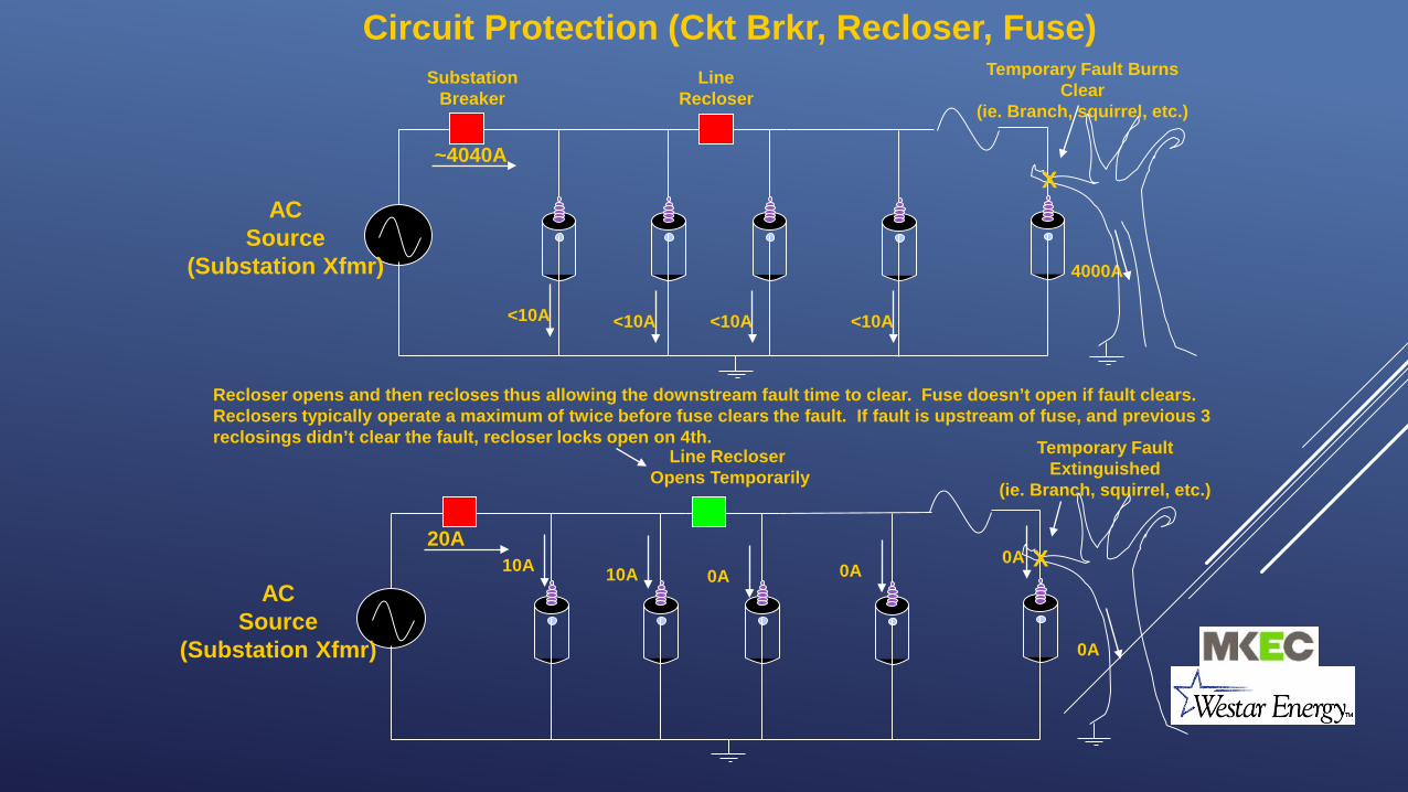
Recloser opens and then recloses thus allowing the downstream fault time to clear. Fuse doesn’t open if fault clears. Reclosers typically operate a maximum of twice before fuse clears the fault. If fault is upstream of fuse, and previous 3 reclosings didn’t clear the fault, recloser locks open on 4th.
Circuit Protection (Ckt Brkr, Recloser, Fuse)
<10A <10A <10A <10A
0A 0A0A
LineRecloser
Temporary Fault Burns Clear
(ie. Branch, squirrel, etc.)
4000A
X
Line RecloserOpens Temporarily
Temporary Fault Extinguished
(ie. Branch, squirrel, etc.)
0A
X

Practical Overcurrent Device Application
Sub Brkr(560A)
Line Recloser
100T
(V4H 100A, 2A2B)
30T
30T
15T 15T
65T
Downstream fuses sized 2 sizes smaller than upstream fuses
Taps directly off of main feeder sized according to substation
xfmr size:115KV/≥10.5MVA – 100T34.5KV/≥10.5MVA-80T
34.5KV/<10.5MVA-Consult EDE
Fuses immediately downstream from recloser sized according to EOP 7203 to coordinate with upstream
recloser
Transformer fuses sized in
accordance with LCS 9-040 thru
9-070 Capacitors fused in accordance with LCS 10-020

Substation Breaker – Fuse Coordination

Fuse – Fuse Incorrect Coordination

Fuse – Fuse Correct Coordination

Recloser – Fuse Coordination
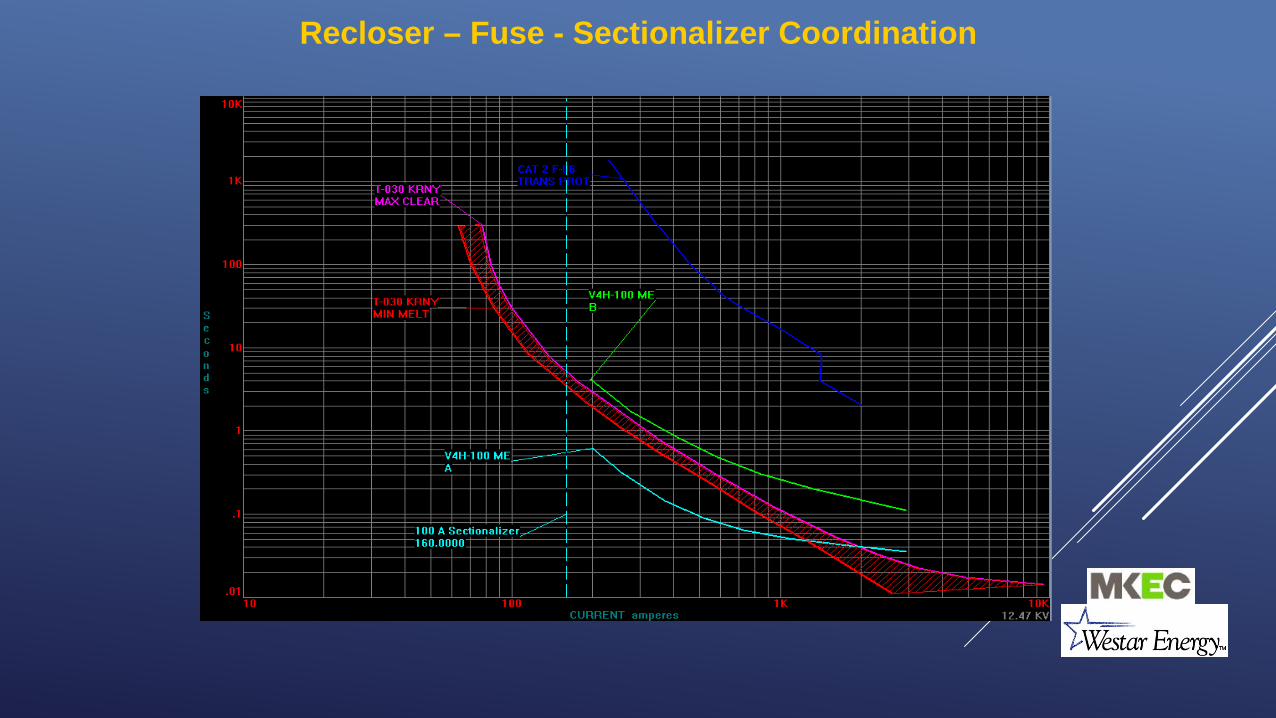
Recloser – Fuse - Sectionalizer Coordination

TUTORIAL ON ELECTRIC ARC HAZARDSSUBSTATION PROTECTION AND CONTROL

Four Factors Determine Hazard
• Length of arc• Distance to arc• Current in arc• Duration of arc

Length of Arc• Determined by dielectric strength of air
(10kV/in)• Heavily influenced by bus/line spacing• The longer the arc, the greater the
incident energy• OSHA provides suggested lengths in
Table 5 of Appendix E
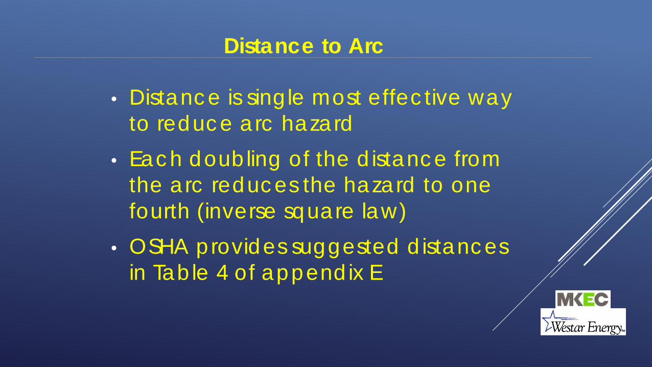
Distance to Arc
• Distance is single most effective way to reduce arc hazard
• Each doubling of the distance from the arc reduces the hazard to one fourth (inverse square law)
• OSHA provides suggested distances in Table 4 of appendix E

Current in Arc
• The greater the current, the greater the incident energy
• Significantly affected at low voltage by arc impedance
• Very little control over this

Duration of Arc
• The sooner that the arc can be extinguished, the lower the incident energy
• High speed tripping can have a dramatic effect on reducing incident energy