Cobra-S - KRIMP & WEDGE, INC. · Cobra-S solid dielectric, three phase reclosers combine the time...
8
Solid Dielectric, Three Phase Reclosers Providing electronic three phase overcurrent protection for systems rated through 38kV, 800A continuous current, 12.5/16kA symmetrical interrupting • Control flexibility • Maintenance-free operation • Overhead and substation designs • Ease of installation • Smart Grid/Lazer ® solutions Catalog Cobra-S Cobra-S
Transcript of Cobra-S - KRIMP & WEDGE, INC. · Cobra-S solid dielectric, three phase reclosers combine the time...

Solid Dielectric, Three Phase Reclosers
Providing electronic three phase overcurrent protection for systems rated through 38kV, 800A continuous current, 12.5/16kA symmetrical interrupting
• Control flexibility
• Maintenance-free operation
• Overhead and substation designs
• Ease of installation
• Smart Grid/Lazer® solutions
Catalog Cobra-S
Cobra-S

G & W E L E C T R I C P A G E 2
Cobra-S
Cobra-S solid dielectric, three phase reclosers combine the time proven reliability of electronically controlled, vacuum fault interrupters with the maintenance benefits of a solid dielectric insulated device. The reclosers are designed for three phase automatic or manual trip opera-tion providing overcurrent protection for systems rated up to 38kV maximum, 800A continuous, and 12.5/16kA rms symmetrical interrupting.
FeaturesReliable Performance - The Cobra-S recloser utilizes a time proven epoxy system to fully encapsulate the vacuum interrupters. This system provides excellent insulation prop-erties while providing a void-free construction. The Cobra-S recloser utilizes the latest in magnetic actuator technology.
Control Flexibility - The Cobra-S recloser is designed to work with a variety of different controls.
Operator Safety - Vacuum interrupters are sealed within a solid dielectric insulation. A hookstick operable manual trip and lockout handle prohibits operation either from the control or remotely. A mechanical blocking device further assures against accidental close. An open and closed contact indicator verifies contact position. Contact status and lockout condition can also be verified at the control.
Maintenance-free - Solid dielectric insulation provides a maintenance-free installation. Electronic equipment as-sociated with the operation of the magnetic actuator is located inside the control.
Ease of Installation - Mounting bracket with key hole and lifting provisions provide ease of installation. Site-ready designs provide all accessories including mounting brack-et, arresters and voltage transformers preassembled prior to shipment significantly reducing installation time. The control cable brings all current, the handle status and trip/close information into the control.
Application Flexibility - Units are designed for overhead, and substation applications. Removable silicone insula-tors are standard for overhead applications. This feature permits easy field replacement if an insulator is damaged. Higher external BIL rated insulators can also be retrofitted if necessary.
Smart Grid / Lazer® Automation Solutions - The Cobra-S is automation ready, simplifying conversion for any future automation requirements. A multi-ratio current transformer is encapsulated within the module. The current transform-er is provided at ratios of 500:1 and 1000:1. Inputs to the control are field changeable.
Complete automation packages are available offering a pre-engineered solution for applications requiring intel-ligent automatic switching and power restoration. The packages feature one or more protective relays, equipped with distribution and communication capabilities. Avail-able communication devices include fiber optic transceiv-ers and wireless radio. The typical control paired with the Cobra-S is the SEL-351R4.
p 15kV Cobra-S recloser with polemount center bracket and surge arrestor provisions.
Catalog Numbers
Voltage Class Catalog Number
15.5kV Cobra-S-15/M [*] - [**]27kV Cobra-S-27/M [*] - [**]38kV Cobra-S-38/M [*] - [**]
* Continuous Current (Amp) = 630 or 800** Short Circuit Current (kA) = 12.5 or 16

G & W E L E C T R I C P A G E 3
p Manual trip handle prohibits electronic closing operation through the control and features mechanical block providing the utmost in safety.
CoNtrol CapabilitiesVarious controls are available depending on application requirements. Typical control settings include:• Minimum trip for phase, ground and sensitive ground
faults.• Numerous pre-programmed and user-defined time
current curves for sensing phase or ground faults.• Three independent recloser interval times. Capable
of up to four shots to lockout.• Reset time.• Sequence coordination. • Cold load pickup. • Advanced parameters. Refer to control specifications
for more details.
maNual trip operatioNOperation of the hookstick operable manual trip handle trips and locks out the recloser. A contact position indi-cator is provided indicating open or closed status of the contacts. Module contact status is also displayed at the control. Operation of the manual trip handle disables any local or remote closing operation until the handle is reset. A mechanical blocking device further assures against ac-cidental close. The handle is operable from ground level with a hookstick. Once reset, the recloser can be closed from the control.
p SEL-351R4 Recloser control.6-pin CT interface pinout
A A phase
B NCC B phaseD C phaseE NCF N phase
14-pin control cable pinout
A 52b input (w/ 69)B 52a inputC 52a outputD 52b output (w/ 69)K Positive CoilJ Negative CoilF TripH CloseG Close/open common signal

G & W E L E C T R I C P A G E 4
Approx. dimensions*- inches. (mm)15.5kV 27kV 38kV
A 42 (1067) 47 (1204) 51 (1295)B 39 (991) 44 (1118) 48 (1219)
Insulator FlexibilityPolemounted units can be equipped with horizontal and a vertical insulator. Insulators are removable. This feature permits easy field replacement if an insulator is damaged. Higher external BIL rated insulators can also be retro-fitted if necessary.
Polemount Center Bracket*
Cobra-S
15.5"(394mm)
15.5"(394mm)
48.6"(1235mm)
A
* Dimensions are approximate. Do not use for construction. Galvanized steel bracket is standard. Stainless steel is available.
B
Provisions for Lightning Arresters
iNterFaCe CoNFiguratioNs
p 6-pin CT connector and 14 -pin control connector.
Connector configuration
The Cobra-S reclosers come with various interface configurations depending on the control used. The tables below give additional details of the connectors for each of the following configurations:
G & W E L E C T R I C P A G E 5* Dimensions are approximate. Do not use for construction.
Substation Mount Recloser* Substation frames are adjustable. Standard frames are galvanized. Stainless steel is available. Custom frames can be designed for direct replacement of existing reclosers.
For applications where extended creepage is required, longer insulators can be applied up to 940mm of creepage distance. The mechanism housing for substation applications is rated IP45 for maximum protection from water intrusion.
Bottom View
15.5"(394mm)
32.9"(836mm)
MOUNTING
34.8"(885mm)
30"(766mm)
48.2"(1225mm)
24"(610mm)
22"(559mm)
70.3"(1788mm)
45.1"(1146mm)
15.5"(394mm)
137.7”(3500mm)MAXIMUM
92.6”(2354mm)MINIMUM
ADJUSTABLEHEIGHT

G & W E L E C T R I C P A G E 6
Voltage Class (kV) 15 25 35
Max System Voltage (kV) 15.5 27 38
BIL (kV) 110 125 150
Continuous Current (A) 800 800 800
60Hz Withstand, kV rms Dry, 1 min 50 60 70
60Hz Withstand, kV rms Wet, 10 sec 45 50 60
Interrupting Rating RMS (kA) 16 16 12.5
Making Current, RMS, asym, KA 24 24 20
Peak, asym (kA) 41.4 41.4 32
Short Circuit Current, kA sym, 3 second 16 16 12.5
Mechanical Operations 10K 10K 10K
Typical Specifications
A. GENERALThis specification covers the requirements for an elec-tronically controlled, mechanically ganged solid dielectric vacuum recloser for use on distribution systems through 38kV. The recloser shall be manufactured by G&W Elec-tric Company designated as Cobra-S solid dielectric re-closer. Recloser configuration shall be (check one):___ Polemount, center___ Substation, 90° mount___ Substation, 45° mount
B. DESIGN RATINGS AND STANDARDSReclosers shall be designed, tested and built per IEEE C37.60 and IEC 62271-111 standards. Certified test reports shall be provided. The recloser shall be rated: (select column):
C. RECLOSER CONSTRUCTIONC1: Mechanism EnclosureThe magnetic actuator and corresponding linkage assem-bly shall be housed within a light gray painted stainless steel tank. A contact position indicator easily visible from the ground, a mechanical counter and air vent shall be provided.
C2. Operating MechanismThe operating mechanism shall utilize a magnetic actuator for opening and closing of the vacuum interrupters. The magnetic actuator shall be powered by capacitors located in the control. The manual trip and lockout handle shall be made of stainless steel for maximum corrosion resistance. Vacuum interrupter contact position indication shall be ac-complished using green (open) and red (closed) indicators located on the bottom of the tank and through LEDs inside the control.
C3. Vacuum InterruptersInterruption of the fault or load currents shall be accom-plished through vacuum interrupters located inside the solid dielectric modules.
C4. Solid Dielectric ModulesThe solid dielectric modules shall utilize a time-proven solid dielectric epoxy insulation to fully encapsulate each of the three vacuum interrupters. The solid dielectric modules shall incorporate a high impact poly-carbonate, track resis-tant, UV stable covering. The operating temperature range shall be -40°C to +65°C. A dual ratio, 500:1 and 1000:1, cur-rent transformer shall be integrally molded into each mod-ule. CT accuracy shall be +/-1%. Modules shall be molded with one (1) source side and one (1) load side, IEC appara-tus bushing interfaces. The bushing interfaces shall accom-modate either connection of an underground cable elbow for padmount applications or silicone insulators for pole top and substation applications.
C5. BushingsBushing types shall be (check one):For Overhead design:___ Air insulated, removable silicone insulators over an IEC bushing interfaceFor Riser Pole:__ Air insulated, silicone insulators on one side and elbow connectors on the other side.For Padmount design:___ 600A apparatus bushing

G & W E L E C T R I C P A G E 7
D. OPERATIONMonitoring of the circuit shall be accomplished using internal multi-ratio current transformers. The unit shall be powered by an external 220 VAC source. In the event main power is lost, the unit shall have trip/close operating capabilities through the battery located in the control.
The magnetic actuator shall use a permanent magnet to hold a solenoid plunger in the closed position while maintaining the trip spring charged. Trip/close operation shall be accom-plished by energizing the magnetic coil which generates a magnetic flux in the opposite direction and releases the trip spring. The trip spring guarantees an open gap of the con-tacts inside the vacuum interrupter resulting in a fail-safe op-eration.
Recloser sequencing, tripping and overcurrent sensing, shall be an automatic function of the electronic control. Manual trip and lockout shall be provided by an external, hook-stick operable handle. Operation of the manual trip handle shall activate a mechanical block device, disabling any local or re-mote closing operation until the handle is reset.
E. SMART GRID / LAZER® AUTOMATIONThe recloser shall be automation ready simplifying conver-sion for any future automation requirements.
F. ELECTRONIC CONTROLSThe standard recloser control shall be the Schweitzer model SEL-351R4. The recloser shall be provided with a 14-pin control interface and a 6-pin CT cable.
G. FACTORY PRODUCTION TESTSEach individual recloser shall undergo a mechanical opera-tion check verifying contact trip/close velocity, travel profile, timing and phase synchronicity. The recloser shall be AC hipot tested one minute phase-to-phase, phase-to-ground and across the open contacts. Circuit resistance shall be checked on all phases. Time overcurrent tests shall be con-ducted to verify minimum pick up level performance. Sys-tem testing shall be performed on each recloser with their respective matching control and any other site-ready add-on such as lightning arrester and potential transformers.
H. STANDARD COMPONENTSThe following shall be included as standard:1. Lifting provisions2. Grounding provisions3. Mechanical counter4. Manual trip and lockout handle with true mechanical block5. SEL-351R recloser control and associated control cable6. Fail-safe mechanically ganged operations7. Solid dielectric epoxy modules with three dual ratio CT’s8. Arrester mounting provisions (overhead applications only)9. Field changeable silicone insulators10. Galvanized center polemount frame
I. OPTIONSThe following options shall be supplied: (Check as necessary)___ NEMA 2-hole aerial lugs___ NEMA 4-hole aerial lugs___ Clamp style aerial lugs (#2- 500 kcmil)___ Clamp style aerial lugs (250-750 kcmil)___ 4/0 brass eyebolt ground lug___ AC connectorized cable for heaters and power source to the magnetic actuator circuitry___ Stainless steel polemount center bracket with arrester provisions on the load and source side.___ Galvanized steel substation frame.___ Polemount site-ready assembly___ Lightning arresters___ External 0.75 KVA solid dielectric voltage transformer (0.3% accuracy) for 120 VAC supply power with hardware to mount on standard frame___ High impact, UV stable wildlife protectors for source and load insulators
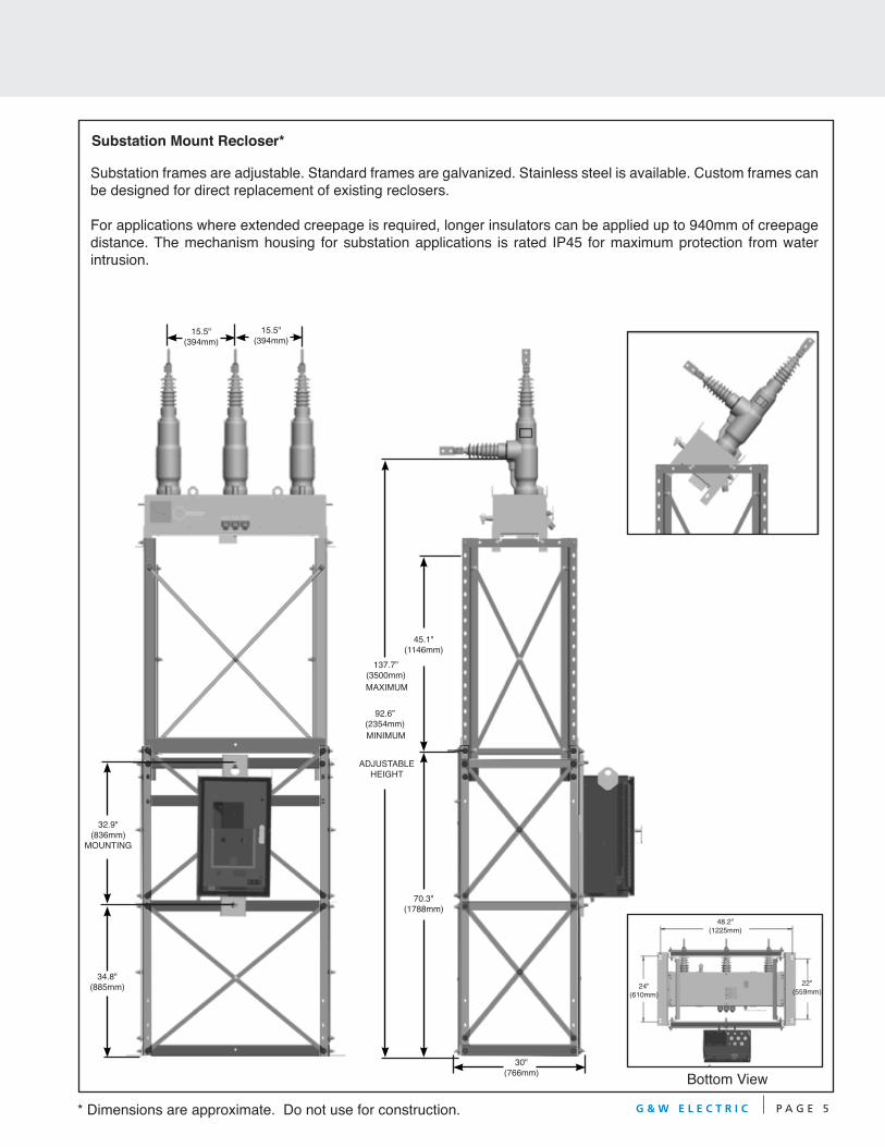
G&W offers a complete line of smart distribution voltage equipment including:
SF6 Insulated Switchgear• To 38kV, 25kA interrupting
• Submersible vault and padmount
• Smart Grid / Lazer® solutions
• Load and Fault Interrupting
Solid Dielectric Switchgear
Solid Dielectric Reclosers• To 38kV, 12.5kA interrupting
• To 27kV, 16kA interrupting
• Overhead, substation and padmount
• Smart Grid / Lazer® solutions
• Single phase and three phase
• Six voltage sensing available
Lazer® Automation
• Multiple levels of protection
• Open, flexible communication
• Pre-engineered, factory tested
• Transfer, loop, and network applications
G&W Electric Company (Headquarters)305 W. Crossroads PkwyBolingbrook, IL 60440-4938 USATel 708.388.5010 Fax 708.388.0755
www.gwelec.comISO 9001:2008 CertifiedISO 14001:2004 Certified
G&W ShanghaiNo. 8 Qing Yun RoadZhang Jiang Hi-Tech ParkPudong, Shanghai, China 201203Tel +86-21-5895-8648Fax +86-21-5895-6829
www.gwelec.com.cn
Catalog Cobra-SJanuary, 2015
• To 38kV, 16kA interrupting
• Submersible vault and padmount
• Smart Grid / Lazer® solutions
• Single phase and three phase
• Integral Visible Break Designs