Sierra Extended Cab Sierra Crew Cab PowerBoard - … Extended Cab 2007 – Current ... (Silverado...
15
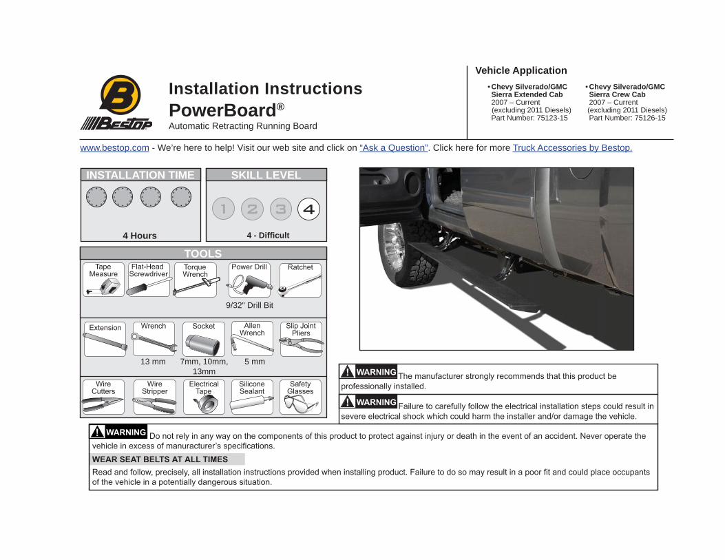
Installation Instructions INSTALLATION TIME SKILL LEVEL 4 Hours 4 - Difficult TOOLS Vehicle Application 9/32" Drill Bit • Chevy Silverado/GMC Sierra Extended Cab 2007 – Current (excluding 2011 Diesels) Part Number: 75123-15 Automatic Retracting Running Board 7mm, 10mm, 13mm 13 mm 5 mm www.bestop.com - We’re here to help! Visit our web site and click on “Ask a Question”. Click here for more Truck Accessories by Bestop. • Chevy Silverado/GMC Sierra Crew Cab 2007 – Current (excluding 2011 Diesels) Part Number: 75126-15 PowerBoard ®
Transcript of Sierra Extended Cab Sierra Crew Cab PowerBoard - … Extended Cab 2007 – Current ... (Silverado...
Installation Instructions
INSTALLATION TIME SKILL LEVEL
4 Hours 4 - Diffi cult
TOOLS
Vehicle Application
9/32" Drill Bit
• Chevy Silverado/GMC Sierra Extended Cab
2007 – Current (excluding 2011 Diesels) Part Number: 75123-15
Automatic Retracting Running Board
7mm, 10mm,13mm
13 mm 5 mm
www.bestop.com - We’re here to help! Visit our web site and click on “Ask a Question”. Click here for more Truck Accessories by Bestop.
• Chevy Silverado/GMC Sierra Crew Cab
2007 – Current (excluding 2011 Diesels) Part Number: 75126-15PowerBoard®
PowerBoard® – Installation Instructions
Rev. X 0115 75123 / 75126 pg. 2
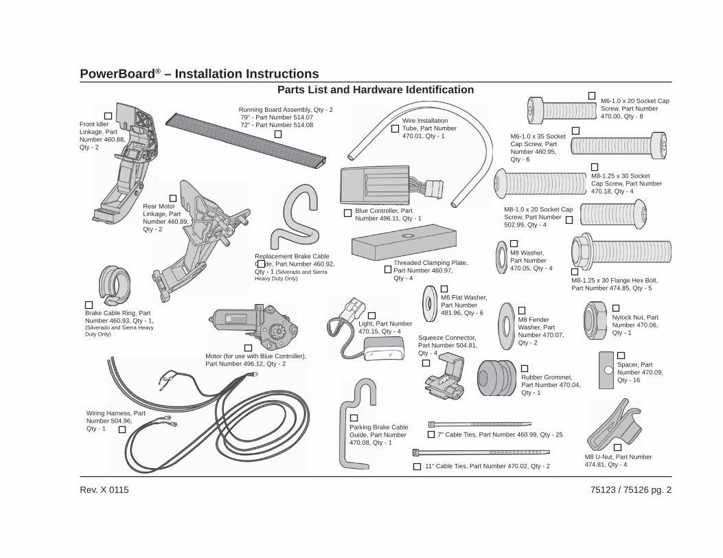
Wire Installation Tube, Part Number 470.01, Qty - 1
Parts List and Hardware Identifi cation
Wiring Harness, Part Number 504.96, Qty - 1
7" Cable Ties, Part Number 460.99, Qty - 25
Rubber Grommet, Part Number 470.04, Qty - 1
Brake Cable Ring, Part Number 460.93, Qty - 1, (Silverado and Sierra Heavy Duty Only)
Front Idler Linkage, Part Number 460.88, Qty - 2
Rear Motor Linkage, Part Number 460.89, Qty - 2
Replacement Brake Cable Guide, Part Number 460.92, Qty - 1 (Silverado and Sierra Heavy Duty Only)
Blue Controller, Part Number 496.11, Qty - 1
Light, Part Number 470.15, Qty - 4
11" Cable Ties, Part Number 470.02, Qty - 2
M6-1.0 x 20 Socket Cap Screw, Part Number 470.00, Qty - 8
M6-1.0 x 35 Socket Cap Screw, Part Number 460.95, Qty - 6
M8-1.25 x 30 Socket Cap Screw, Part Number 470.18, Qty - 4
M8-1.25 x 30 Flange Hex Bolt, Part Number 474.85, Qty - 5
M8 Washer, Part Number 470.05, Qty - 4
M8 Fender Washer, Part Number 470.07, Qty - 2
Nylock Nut, Part Number 470.06, Qty - 1
Threaded Clamping Plate, Part Number 460.97, Qty - 4
Squeeze Connector, Part Number 504.81, Qty - 4
M8 U-Nut, Part Number 474.81, Qty - 4
Parking Brake Cable Guide, Part Number 470.08, Qty - 1
Spacer, Part Number 470.09, Qty - 16
M6 Flat Washer, Part Number 481.96, Qty - 6
Motor (for use with Blue Controller), Part Number 496.12, Qty - 2
Running Board Assembly, Qty - 2 79” - Part Number 514.07 72" - Part Number 514.08
M8-1.0 x 20 Socket Cap Screw, Part Number 502.99, Qty - 4
PowerBoard® – Installation Instructions
Rev. X 0115 75123 / 75126 pg. 3
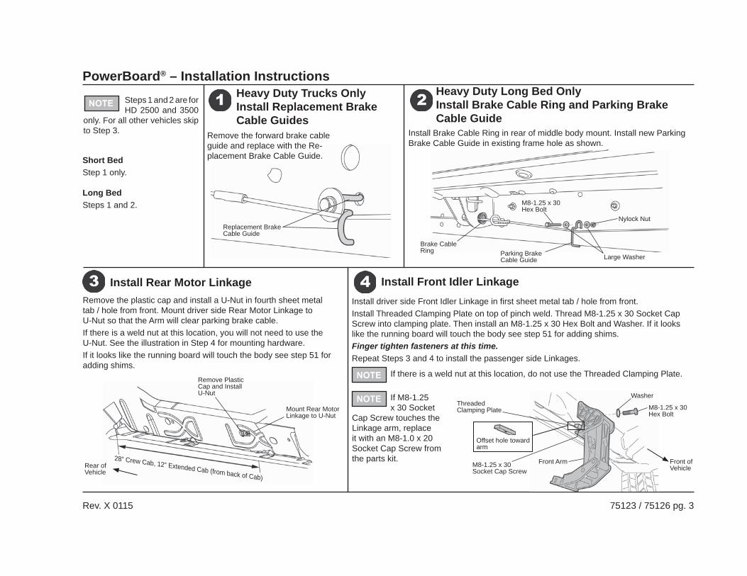
Steps 1 and 2 are for HD 2500 and 3500
only. For all other vehicles skip to Step 3.
Short BedStep 1 only.
Long BedSteps 1 and 2.
Remove the forward brake cable guide and replace with the Re-placement Brake Cable Guide.
Replacement Brake Cable Guide
Heavy Duty Trucks OnlyInstall Replacement Brake Cable Guides
Install Brake Cable Ring in rear of middle body mount. Install new Parking Brake Cable Guide in existing frame hole as shown.
Parking Brake Cable Guide
Brake Cable Ring
Heavy Duty Long Bed OnlyInstall Brake Cable Ring and Parking Brake Cable Guide
Install driver side Front Idler Linkage in fi rst sheet metal tab / hole from front.Install Threaded Clamping Plate on top of pinch weld. Thread M8-1.25 x 30 Socket Cap Screw into clamping plate. Then install an M8-1.25 x 30 Hex Bolt and Washer. If it looks like the running board will touch the body see step 51 for adding shims.Finger tighten fasteners at this time.Repeat Steps 3 and 4 to install the passenger side Linkages.
Remove the plastic cap and install a U-Nut in fourth sheet metal tab / hole from front. Mount driver side Rear Motor Linkage to U-Nut so that the Arm will clear parking brake cable.If there is a weld nut at this location, you will not need to use the U-Nut. See the illustration in Step 4 for mounting hardware.If it looks like the running board will touch the body see step 51 for adding shims.
Install Front Idler LinkageInstall Rear Motor Linkage
M8-1.25 x 30 Hex Bolt
Large Washer
Nylock Nut
Front Arm
Threaded Clamping Plate M8-1.25 x 30
Hex Bolt
Washer
Front of VehicleM8-1.25 x 30
Socket Cap Screw
Offset hole toward arm
Remove Plastic Cap and Install U-Nut
Mount Rear Motor Linkage to U-Nut
28" Crew Cab, 12" Extended Cab (from back of Cab)
Rear of Vehicle
If there is a weld nut at this location, do not use the Threaded Clamping Plate.
If M8-1.25 x 30 Socket
Cap Screw touches the Linkage arm, replace it with an M8-1.0 x 20 Socket Cap Screw from the parts kit.

PowerBoard® – Installation Instructions
Rev. X 0115 75123 / 75126 pg. 4
Do not ground wrench when engaged with nut.
Route long end of wire harness above engine and down through drivers side wheel well. Cable tie harness to cowling clips on fi re wall. Route short end down passengers side.
Route Wire Harness – Gas Engine
Use the two (2) 11" Cable Ties to mount the Controller to the support arm next to the battery (behind the support arm on diesel engines).Plug in the Wire Harness. Make sure that the locking tabs engage.
Install Controller and Wire Harness
Controller
Wire Harness
Remove the fuse from the Wiring Harness.
Remove the fuse from the Wiring Harness. Failure to do so could result in severe electrical shock which could harm the installer and/or damage the vehicle.
Remove Fuse from Wiring Harness
Attach power lead (RED wire) to positive pole on the battery.Attach ground lead to negative battery pole.
Attach Leads
Wire Harness
Wire Harness – Secure with Cable Ties
On hybrid models mount the Controller on the driver’s side.
On hybrid models route the long end of the wire harness down the passenger wheel well and the short end down the driver’s side.
PowerBoard® – Installation Instructions
Rev. X 0115 75123 / 75126 pg. 5
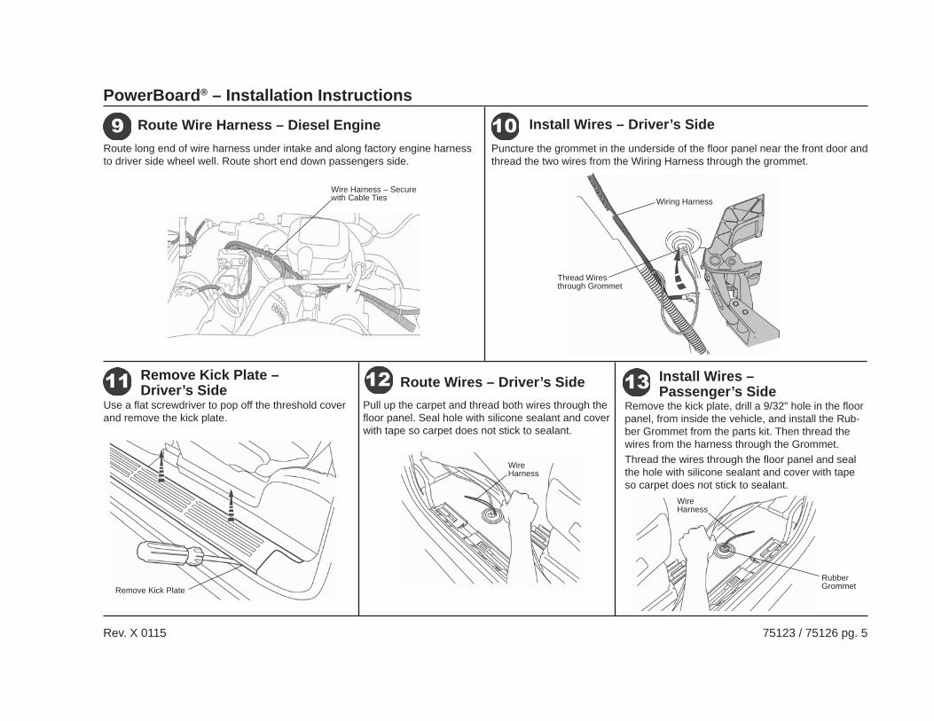
Route long end of wire harness under intake and along factory engine harness to driver side wheel well. Route short end down passengers side.
Route Wire Harness – Diesel Engine
Wire Harness – Secure with Cable Ties
Puncture the grommet in the underside of the fl oor panel near the front door and thread the two wires from the Wiring Harness through the grommet.
Install Wires – Driver’s Side
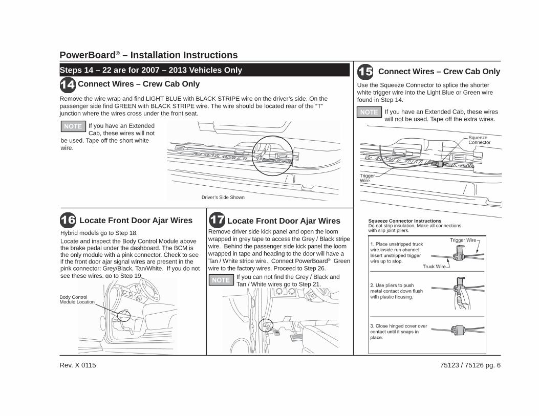
Use a fl at screwdriver to pop off the threshold cover and remove the kick plate.
Remove Kick Plate
Remove Kick Plate – Driver’s Side
Wiring Harness
Thread Wires through Grommet
Pull up the carpet and thread both wires through the fl oor panel. Seal hole with silicone sealant and cover with tape so carpet does not stick to sealant.
Route Wires – Driver’s Side
Wire Harness
Remove the kick plate, drill a 9/32" hole in the fl oor panel, from inside the vehicle, and install the Rub-ber Grommet from the parts kit. Then thread the wires from the harness through the Grommet. Thread the wires through the fl oor panel and seal the hole with silicone sealant and cover with tape so carpet does not stick to sealant.
Install Wires – Passenger’s Side
Wire Harness
Rubber Grommet
PowerBoard® – Installation Instructions
Rev. X 0115 75123 / 75126 pg. 6
Remove the wire wrap and fi nd LIGHT BLUE with BLACK STRIPE wire on the driver’s side. On the passenger side fi nd GREEN with BLACK STRIPE wire. The wire should be located rear of the “T” junction where the wires cross under the front seat.
Connect Wires – Crew Cab OnlyConnect Wires – Crew Cab Only
If you have an Extended Cab, these wires will not
be used. Tape off the short white wire.
Use the Squeeze Connector to splice the shorter white trigger wire into the Light Blue or Green wire found in Step 14.
If you have an Extended Cab, these wires will not be used. Tape off the extra wires.
Trigger Wire
Squeeze Connector
Squeeze Connector InstructionsDo not strip insulation. Make all connections with slip joint pliers.Hybrid models go to Step 18.
Locate and inspect the Body Control Module above the brake pedal under the dashboard. The BCM is the only module with a pink connector. Check to see if the front door ajar signal wires are present in the pink connector: Grey/Black, Tan/White. If you do not see these wires, go to Step 19.
Locate Front Door Ajar WiresRemove driver side kick panel and open the loom wrapped in grey tape to access the Grey / Black stripe wire. Behind the passenger side kick panel the loom wrapped in tape and heading to the door will have a Tan / White stripe wire. Connect PowerBoard® Green wire to the factory wires. Proceed to Step 26.
Locate Front Door Ajar Wires
If you can not fi nd the Grey / Black and Tan / White wires go to Step 21.
Body Control Module Location
Driver’s Side Shown
Steps 14 – 22 are for 2007 – 2013 Vehicles Only
PowerBoard® – Installation Instructions
Rev. X 0115 75123 / 75126 pg. 7
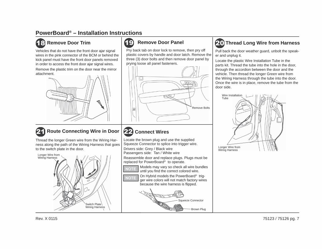
Vehicles that do not have the front door ajar signal wires in the pink connector of the BCM or behind the kick panel must have the front door panels removed in order to access the front door ajar signal wires. Remove the plastic trim on the door near the mirror attachment.
Remove Door TrimPry back tab on door lock to remove, then pry off plastic covers by handle and door latch. Remove the three (3) door bolts and then remove door panel by prying loose all panel fasteners.
Remove Door Panel
Remove Bolts
Pull back the door weather guard, unbolt the speak-er and unplug it.Locate the plastic Wire Installation Tube in the parts kit. Thread the tube into the hole in the door, through the accordion between the door and the vehicle. Then thread the longer Green wire from the Wiring Harness through the tube into the door. Once the wire is in place, remove the tube from the door side.
Longer Wire from Wiring Harness
Wire Installation Tube
Thread Long Wire from Harness
Thread the longer Green wire from the Wiring Har-ness along the path of the Wiring Harness that goes to the switch plate in the door.
Switch Plate Wiring Harness
Longer Wire from Wiring Harness
Route Connecting Wire in DoorLocate the brown plug and use the supplied Squeeze Connector to splice into trigger wire.Drivers side: Grey / Black wirePassengers side: Tan / White wireReassemble door and replace plugs. Plugs must be replaced for PowerBoard® to operate.
Connect Wires
Brown Plug
Squeeze Connector
Models may vary so check all wire bundles until you fi nd the correct colored wire.On Hybrid models the PowerBoard® trig-ger wire colors will not match factory wires because the wire harness is fl ipped.
PowerBoard® – Installation Instructions
Rev. X 0115 75123 / 75126 pg. 8
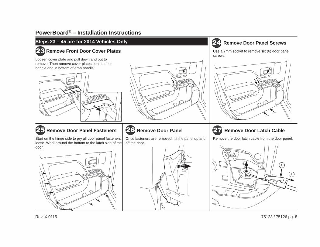
Remove Front Door Cover PlatesRemove Door Panel ScrewsSteps 23 – 45 are for 2014 Vehicles Only
Loosen cover plate and pull down and out to remove. Then remove cover plates behind door handle and in bottom of grab handle.
Remove Door Panel Remove Door Latch CableRemove Door Panel FastenersOnce fasteners are removed, lift the panel up and off the door.
Remove the door latch cable from the door panel.
Use a 7mm socket to remove six (6) door panel screws.
Start on the hinge side to pry all door panel fasteners loose. Work around the bottom to the latch side of the door.
1
2
PowerBoard® – Installation Instructions
Rev. X 0115 75123 / 75126 pg. 9
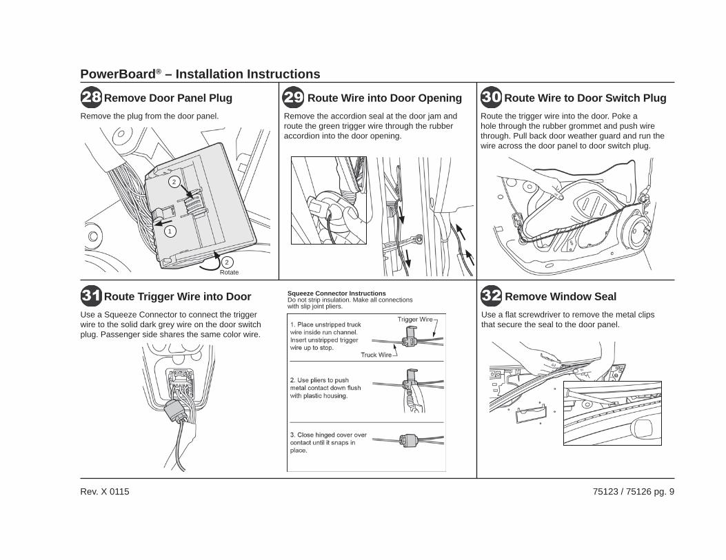
Remove Door Panel Plug
Route Trigger Wire into Door
Route Wire into Door Opening
Remove Window Seal
Route Wire to Door Switch PlugRemove the plug from the door panel.
Use a Squeeze Connector to connect the trigger wire to the solid dark grey wire on the door switch plug. Passenger side shares the same color wire.
Remove the accordion seal at the door jam and route the green trigger wire through the rubber accordion into the door opening.
Use a fl at screwdriver to remove the metal clips that secure the seal to the door panel.
Route the trigger wire into the door. Poke a hole through the rubber grommet and push wire through. Pull back door weather guard and run the wire across the door panel to door switch plug.
Squeeze Connector InstructionsDo not strip insulation. Make all connections with slip joint pliers.
1
2
2Rotate
PowerBoard® – Installation Instructions
Rev. X 0115 75123 / 75126 pg. 10
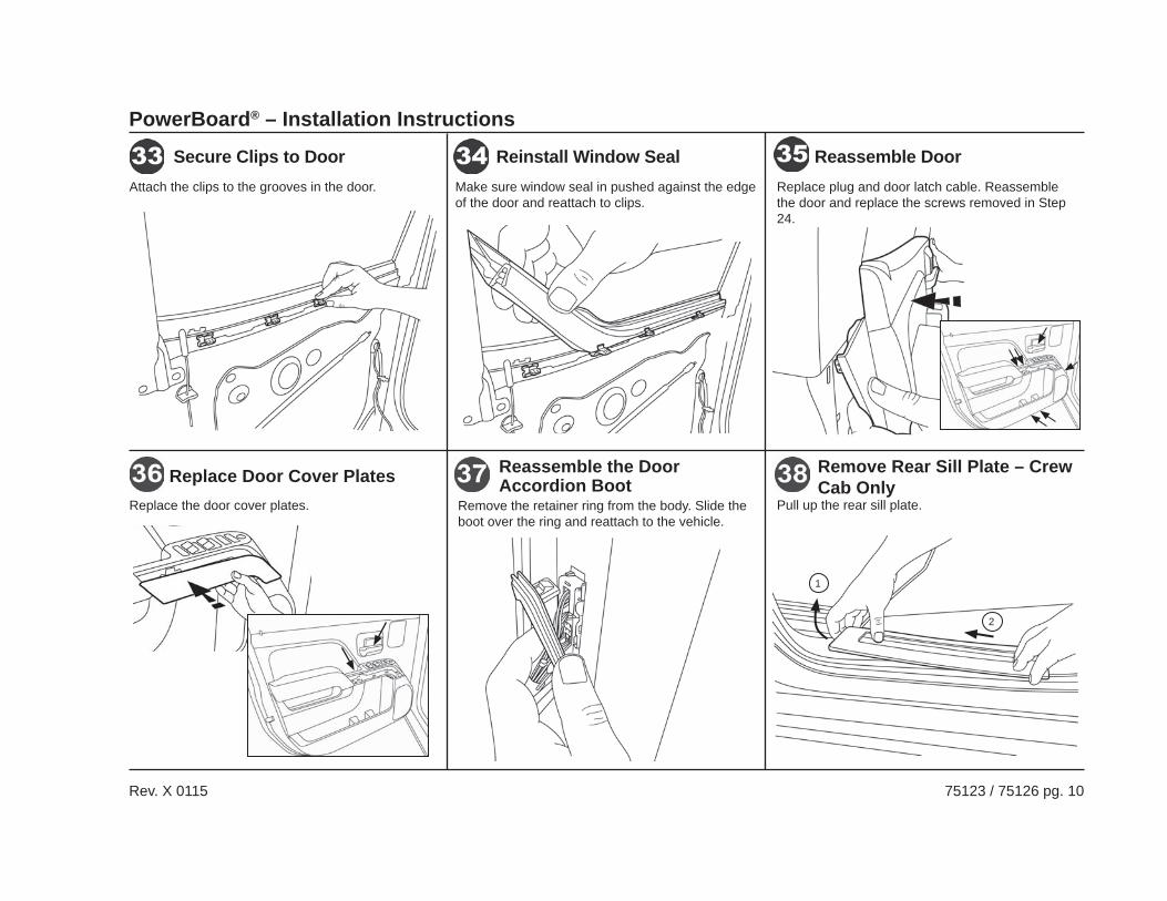
Reassemble DoorReinstall Window SealSecure Clips to Door
Reassemble the Door Accordion Boot
Remove Rear Sill Plate – Crew Cab OnlyReplace Door Cover Plates
Remove the retainer ring from the body. Slide the boot over the ring and reattach to the vehicle.
Pull up the rear sill plate.
Replace plug and door latch cable. Reassemble the door and replace the screws removed in Step 24.
Make sure window seal in pushed against the edge of the door and reattach to clips.
Attach the clips to the grooves in the door.
Replace the door cover plates.
1
2
PowerBoard® – Installation Instructions
Rev. X 0115 75123 / 75126 pg. 11
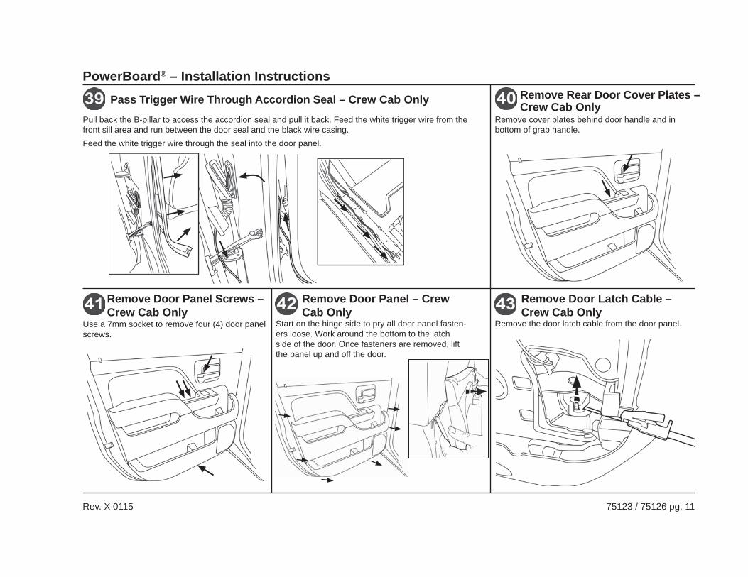
Pass Trigger Wire Through Accordion Seal – Crew Cab OnlyPull back the B-pillar to access the accordion seal and pull it back. Feed the white trigger wire from the front sill area and run between the door seal and the black wire casing.Feed the white trigger wire through the seal into the door panel.
Remove Rear Door Cover Plates – Crew Cab Only
Remove cover plates behind door handle and in bottom of grab handle.
Remove Door Panel Screws – Crew Cab Only
Use a 7mm socket to remove four (4) door panel screws.
Remove Door Panel – Crew Cab Only
Remove Door Latch Cable – Crew Cab Only
Start on the hinge side to pry all door panel fasten-ers loose. Work around the bottom to the latch side of the door. Once fasteners are removed, lift the panel up and off the door.
Remove the door latch cable from the door panel.
PowerBoard® – Installation Instructions
Rev. X 0115 75123 / 75126 pg. 12
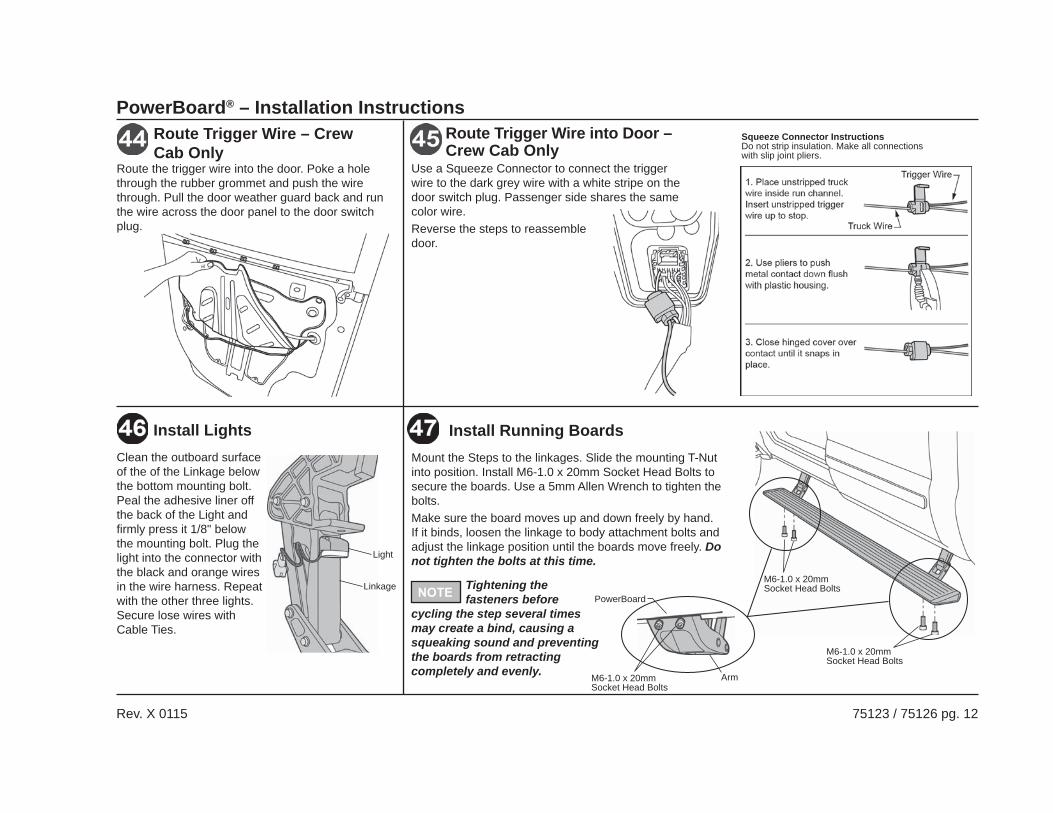
Clean the outboard surface of the of the Linkage below the bottom mounting bolt. Peal the adhesive liner off the back of the Light and fi rmly press it 1/8" below the mounting bolt. Plug the light into the connector with the black and orange wires in the wire harness. Repeat with the other three lights. Secure lose wires with Cable Ties.
Install Lights
Light
Linkage
Install Running BoardsMount the Steps to the linkages. Slide the mounting T-Nut into position. Install M6-1.0 x 20mm Socket Head Bolts to secure the boards. Use a 5mm Allen Wrench to tighten the bolts.Make sure the board moves up and down freely by hand. If it binds, loosen the linkage to body attachment bolts and adjust the linkage position until the boards move freely. Do not tighten the bolts at this time.
M6-1.0 x 20mm Socket Head Bolts
Arm
PowerBoard
M6-1.0 x 20mm Socket Head Bolts
M6-1.0 x 20mm Socket Head BoltsTightening the
fasteners before cycling the step several times may create a bind, causing a squeaking sound and preventing the boards from retracting completely and evenly.
Route Trigger Wire – Crew Cab Only
Route the trigger wire into the door. Poke a hole through the rubber grommet and push the wire through. Pull the door weather guard back and run the wire across the door panel to the door switch plug.
Route Trigger Wire into Door – Crew Cab Only
Use a Squeeze Connector to connect the trigger wire to the dark grey wire with a white stripe on the door switch plug. Passenger side shares the same color wire.Reverse the steps to reassemble door.
Squeeze Connector InstructionsDo not strip insulation. Make all connections with slip joint pliers.
PowerBoard® – Installation Instructions
Rev. X 0115 75123 / 75126 pg. 13
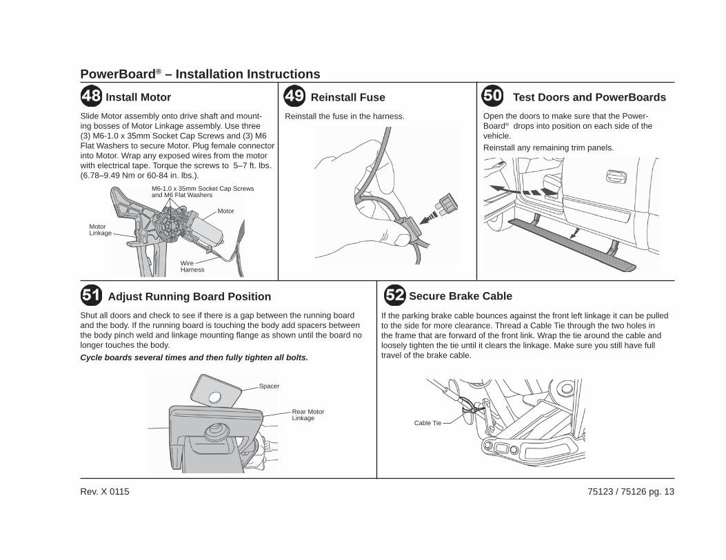
Reinstall the fuse in the harness.
Reinstall FuseOpen the doors to make sure that the Power-Board® drops into position on each side of the vehicle.Reinstall any remaining trim panels.
Test Doors and PowerBoardsSlide Motor assembly onto drive shaft and mount-ing bosses of Motor Linkage assembly. Use three (3) M6-1.0 x 35mm Socket Cap Screws and (3) M6 Flat Washers to secure Motor. Plug female connector into Motor. Wrap any exposed wires from the motor with electrical tape. Torque the screws to 5–7 ft. lbs. (6.78–9.49 Nm or 60-84 in. lbs.).
Install Motor
Motor Linkage
Motor
Wire Harness
M6-1.0 x 35mm Socket Cap Screws and M6 Flat Washers
Spacer
Rear Motor Linkage
Shut all doors and check to see if there is a gap between the running board and the body. If the running board is touching the body add spacers between the body pinch weld and linkage mounting fl ange as shown until the board no longer touches the body.Cycle boards several times and then fully tighten all bolts.
Adjust Running Board PositionIf the parking brake cable bounces against the front left linkage it can be pulled to the side for more clearance. Thread a Cable Tie through the two holes in the frame that are forward of the front link. Wrap the tie around the cable and loosely tighten the tie until it clears the linkage. Make sure you still have full travel of the brake cable.
Secure Brake Cable
Cable Tie
PowerBoard® – Installation Instructions
Rev. X 0115 75123 / 75126 pg. 14
Issue:• Possible cause
Boards do not operate:• Connected to incorrect vehicle wire• Wire connections not secure• Fuse burned• Factory door-ajar circuit inoperable
Board creaks or squeaks during operation:• Gear shaft wedge bolt is loose• Loosen mounting bracket and board attach-
ment screws. Adjust linkages so they are parallel to each other and the noise is gone. Tighten all fasteners.
Intermittent operation:• Wire connections not secure• Bad ground• Bad battery connection
Boards operate randomly:• Wire connections not secure• Connected to incorrect vehicle wire
Board stays down all the time and can be moved by hand:
• Gear shaft wedge screw is missing or looseBoard shakes and or shutters during operation:
• Bad ground• Wire connections not secure• Bad battery connection
One or more doors operate the board and other do not:
• Wire connections not secure
PowerBoard® TroubleshootingConfirming PowerBoard® is functional-black controller:To test if the black controller (460.91), wire harness, motor and lights work, hook up to battery and touch any of the 4 door trigger wires to ground. The board for that side should go down and the lights should turn on. The board should go up and the lights should turn off when the wire is removed from ground.
Boards don’t operate correctly when connected to wires identifi ed in instructions:Unfortunately vehicle manufactures do not consistently keep the same wire colors in their wire harnesses. The PowerBoard® trigger wires need to be connected the factory door-ajar wire that is connected to each door latch switch. The correct wire is likely in the same bundle that is identifi ed in the instructions. If none of them work you can locate the correct wire by removing the door panel and tracing the wire bundle that leads to the door latch.Use an ohm meter or continuity tester to find the door-ajar wire on PowerBoards® with black controllers. The correct wire will go from neutral to ground when the door is opened and return to neutral when the door is shut. Connect one test lead to the negative battery terminal and probe the wires with the other lead. You can use a pin or a Posi-Tap connector to pierce the wire insulation. The correct wire will make the tester go from no continuity to complete continuity when the door opened and return to no continuity when the door is shut. You can also shut the door latch with the door open by pushing on the latch catch with a screw driver.
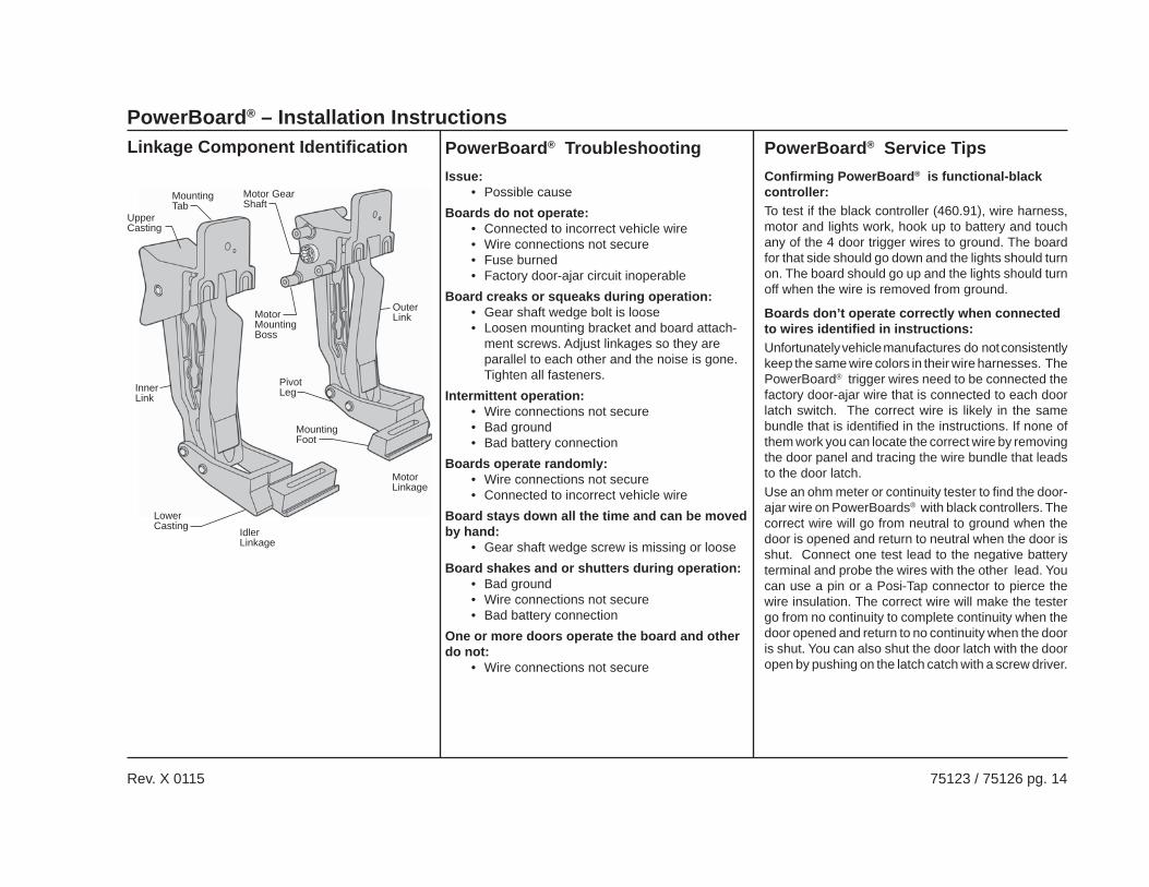
PowerBoard® Service TipsLinkage Component Identifi cation
Motor Gear Shaft
Motor Mounting Boss
Mounting Tab
Upper Casting
Outer Link
Inner Link
Lower Casting
Mounting Foot
Motor Linkage
Idler Linkage
Pivot Leg
PowerBoard® – Installation Instructions
Rev. X 0115 75123 / 75126 pg. 15
LIMITED WARRANTYWe warrant our product to be free from defects in material and workmanship, for the terms specifi ed below, provided there has been normal use and proper maintenance. This warranty applies to the original purchaser only. All remedies under this warranty are limited to the repair or replacement of any item or items found by the factory to be defective within the time period specifi ed. If you have a warranty claim, fi rst you must call our factory at the number below for instructions. You must retain proof of purchase and submit a copy with any items returned for warranty work. Upon completion of warranty work, if any, we will return the repaired or replaced item or items to you freight prepaid. Damage to our products caused by accidents, fi re, vandalism, negligence, misinstallation, misuse, Acts of God, or by defective parts not manufactured by us, is not covered under this warranty. THE WARRANTY TIME PERIOD IS AS FOLLOWS FOR ALL PowerBoards® MANUFACTURED BY OUR COMPANY: THREE YEARS / 36,000 MILES FROM DATE OF PURCHASE.ANY IMPLIED WARRANTIES OF MERCHANTABILITY AND/OR FITNESS FOR A PARTICULAR PURPOSE CREATED HEREBY ARE LIMITED IN DURATION TO THE SAME DURATION AND SCOPE AS THE EXPRESS WRITTEN WARRANTY. OUR COMPANY SHALL NOT BE LIABLE FOR ANY INCIDENTAL OR CONSEQUENTIAL DAMAGE.Some states do not allow limitations on how long an implied warranty lasts, or the exclusion or limitation of incidental or consequential damages, so the above limitations or exclusions may not apply to you. This warranty gives you specifi c legal rights, and you may also have other rights which vary from state to state.
For further information or request for warranty work, please contact:Bestop Inc. Customer ServiceToll-Free: (800)845-3567Main: (303)465-1755E-mail: [email protected]: www.Bestop.com
Care and MaintenanceThe step pad surface and linkage arms should be washed with mild soap and water using a soft brush or sponge to dislodge any mud, dirt or accumulated road grime. Rinse with fresh water and avoid spraying the motors directly. After it is dry, lubricate the hinge with 3-IN-ONE Oil.To prevent slipping, avoid applying waxes, lubricants or protectants like Armor All® to the step surface.
Attention!TrekStep™ SHOULD ALWAYS BE STOWED IN THE RETRACTED POSITION WHEN DRIVING.