SHURFlo manufactures BIB Syrup Beverage pumps … an inlet gas pressure the resulting force driving...
32
HeavyDuty Advantage BIB Gas Pump The SHURflo Heavy Duty Advantage gas driven diaphragm pump is designed for the dispensing of BIB syrups, wines, teas, juices, milk and water. It utilizes a technically proven twin chamber, positive displacement design to maximize performance by minimizing pressure drop. The operation of the SHURflo BIB Gas pump guarantees a steady supply of syrup under pressure to a post-mix dispenser valve that mixes the syrup with water to an exact ratio. The pump is used in conjunction w ith BIB containers and quick disconnect (bag) fittings. The pump features automatic demand and automatic sold-out shut-off for ease of operation. There are several key features in the SHURflo pump which make it unique in the market and best suited to consistently deliver a good quality drink at the dispenser head. The above design configuration results in the greatest efficiency and lowest pressure drop every time the dispensing valve open and closes and thus insuring consistent beverage quality. The standard Heavy Duty Advantage pump features the product outlet on top. SHURflo also offers the FLOport Heavy Duty Advantage gas pump designed to position all fluid and gas ports at the bottom of the pump for maximum compatibility with existing installations. The fitting attachments are also the quick-disconnect type, designed to remain locked securely, yet allowing line connection and disconnection during service. This combination of quick-disconnect fittings and bottom directed ports provide for the greatest ease of use in new systems, and for servicing your existing installations. SHURFlo manufactures BIB Syrup Beverage pumps and Specialty Pumps for Juice and Condiment BIB products. Recommended model numbers . Pepsi Bottler BIB Pump Juice & Condiment Pump
Transcript of SHURFlo manufactures BIB Syrup Beverage pumps … an inlet gas pressure the resulting force driving...

HeavyDuty Advantage BIB Gas Pump The SHURflo Heavy Duty Advantage gas driven diaphragm pump is designed for the dispensing of BIB syrups, wines, teas, juices, milk and water. It utilizes a technically proven twin chamber, positive displacement design to maximize performance by minimizing pressure drop. The operation of the SHURflo BIB Gas pump guarantees a steady supply of syrup under pressure to a post-mix dispenser valve that mixes the syrup with water to an exact ratio. The pump is used in conjunction w ith BIB containers and quick disconnect (bag) fittings. The pump features automatic demand and automatic sold-out shut-off for ease of operation. There are several key features in the SHURflo pump which make it unique in the market and best suited to consistently deliver a good quality drink at the dispenser head.
The above design configuration results in the greatest efficiency and lowest pressure drop every time the dispensing valve open and closes and thus insuring consistent beverage quality. The standard Heavy Duty Advantage pump features the product outlet on top. SHURflo also offers the FLOport Heavy Duty Advantage gas pump designed to position all fluid and gas ports at the bottom of the pump for maximum compatibility with existing installations. The fitting attachments are also the quick-disconnect type, designed to remain locked securely, yet allowing line connection and disconnection during service. This combination of quick-disconnect fittings and bottom directed ports provide for the greatest ease of use in new systems, and for servicing your existing installations. SHURFlo manufactures BIB Syrup Beverage pumps and Specialty Pumps for Juice and Condiment BIB products. Recommended model numbers.
Pepsi Bottler BIB Pump
Juice & Condiment Pump

Technical Specifications – Syrup Beverage Pump Design Two Chamber Double Diaphragm
Power Source CO2 gas, Nitrogen or Clean Compressed Air
Materials of Construction Polypropylene, EPDM, Santoprene, 316 Stainless Steel Temperature Limits 34° - 120°F (1.1° - 49°C)
Weight 1.2 lbs. (0.9 kg.)
7.9" H x 5.7" W x 3.8" D (171 mm x 145 mm x 97 mm) Size FLOport
6.0" H x 5.9" W x 4.3" D (152 mm x 150 mm x 110 mm) Displacement 3.4 oz. (74 cc) / cycle
Suction Lift Activated @ 20 in. Hg. (508 m bar), wet 25 in. Hg. (847 m bar)
Maximum Operating Pressure 85 psi (5.9 bar) Minimum Operating Pressure 20 psi (1.4 bar)
3/8" barb nylon or 1/4", 3/8" or 1/2" barb Stainless steel Liquid Fittings
FLOport Liquid Outlet - 3/8" barb nylon straight
Air Fittings 1/4" barb plastic or barb brass Elbow & Tee w/check valve
Operations Manual, Installation Guidelines, Start-up Procedure, Trouble shooting

BIB Gas Pump Features and Operation
Straight Through Syrup Path- the Path of Least Resistance. The idea behind the SHURflo pump is to move the gas rather than the syrup. This feature has been built in the design of the pump, which provides a straight flow path for the product across the pump. This means the syrup has the least amount of restrictions possible. The fewer the restrictions there are means less pressure drop within the pump and greater CO2 savings. But more important the less pressure drop across the pump the more consistent the quality of the drink. Twin chamber double diaphragm positive displacement with designed Hydraulic Advantage- that is given an inlet gas pressure the resulting force driving the syrup out is greater than the force applied by the gas. This is because the piston surface area to the "gas in" side of the chamber is greater than the effective piston surface area to the "syrup out" side. This difference gives the SHURflo pump a hydraulic boost. Gas (CO2/Nitrogen/Air) Driven- The pump can be operated by either regulated CO2, nitrogen or clean compressed air. The compressed gas drives the pump and does not come in contact with the syrup. The minimum gas pressure is 20 psi (1.4 bar) and the maximum is 85 psi (5.8 bar). The figures below illustrate the flow of gas and flow of syrup when the pump is in operation.
Figure A Figure B Figure A - The CO2 enters the control cover through the poppet valve (which is open on this stroke) into the left CO2 chamber. The CO2 in the left chamber pushes the piston to the right, thus forcing out the syrup in the left liquid chamber (syrup under pressure), while suctioning syrup into the pump to the right chamber (syrup under vacuum). When the piston is fully extended, the switching system activates, closing the poppet valve and diverting the CO2 to the right chamber. Figure B - The CO2 enters the control cover through the poppet valve. The valve blocks the passage into the left chamber, causing the CO2 to be diverted around the outside of the pump to the right chamber. The CO2 in the right chamber pushes the piston to the left, thus forcing out the syrup on the right side of the chamber (syrup under pressure), while pulling syrup into the pump to the left chamber (syrup under vacuum). When the piston is fully extended, the switching system activates, allowing CO2 to enter the left chamber, where the process in Figure A begins.

Automatic Demand- The pump operates only when syrup is needed. When the dispenser valve opens, creating a pressure d rop, the pump operates to maintain syrup line pressure. The pump continues operating until the valve is closed and the syrup line pressure equals the gas pressure. At equalization, the pump stops. Sold Out- The pump operates only when there is an adequate supply of syrup. Vacuum produced by the pump evacuates the syrup within the bag. Once the preset vacuum point is achieved and held, the gas supply to the pump is shut off, causing the pump to stop. When a new BIB is installed, the pump automatically starts and pressurizes the system. The benefit of the sold-out feature is that the outlet line to the dispenser always remains full of syrup.

Post-Mix BIB Dispensing System
The Post Mix BIB Dispensing system consists of the BIB package and the SHURflo BIB Gas pump. The BIB package works in conjunction with the Shurflo gas pump to supply syrup to the dispenser.
Typical Bag In Box Dispensing System The BIB package, consists of a non pressurized 5 gallon (20 liter) flexible bag (other sizes are available), composed of polyethylene and metallized polyester, held inside and supported by a carton box. The polyethylene film, approved by the FDA, is in contact with the syrup in addition to providing the bag strength. The metallized polyester film provides an oxygen barrier to the bag for extended shelf life of product. The SHURflo pump is driven by CO2, compressed air or nitrogen regulated to a proper pressure to supply the system between 20 and 85 psi (1.5 - 5.9 bar). The compressed gas only runs the pump and never comes in contact with the product. The pressurized line from the pump propels the liquid or syrup to the dispensing unit. The pump eliminates the need for check valves and manifolds used in transfer tank systems. The separation of the gas and liquid avoids contamination, foaming and purging of the liquid outlet lines when the BIB is empty. The Shurflo BIB pump ensures drink quality from the first drink to the last. The SHURflo pump is compatible with all types of dispensing equipment. When designing a Post Mix BIB Dispensing System there are certain points to be taken into consideration to ensure long-term operation of the pump and maximizing space efficiency. BIB Gas Pump Pumping Capability Beverage dispensing systems have inherent factors that determine the distance syrup can be delivered. Restrictions within the BIB system’s fluid path will affect pumping capability. Before deciding on a system tubing size, SHURflo recommends estimating system losses by considering the following:
1. Syrup viscosity and temperature (cold plate, re-circ., etc.). 2. Total syrup flow rate of dispensing valve(s) connected to a pump: add flow rate of valve(s)
connected to a single pump. Note: the number of pumps is at least one pump per flavor. If there are five flavors in the dispensing unit, you will need five pumps.
3. Inside diameter of the outlet/inlet tubing, fittings, etc. 4. Vertical and horizontal distance of the outlet tubing.
Vertical tubing runs will reduce total tubing run length. To estimate the losses within the vertical distance, use the Maximum Horizontal Tubing Length by Viscosity Tables to Calculate the Maximum Pumping Distance.
Heavy Duty Advantage Juice Pump
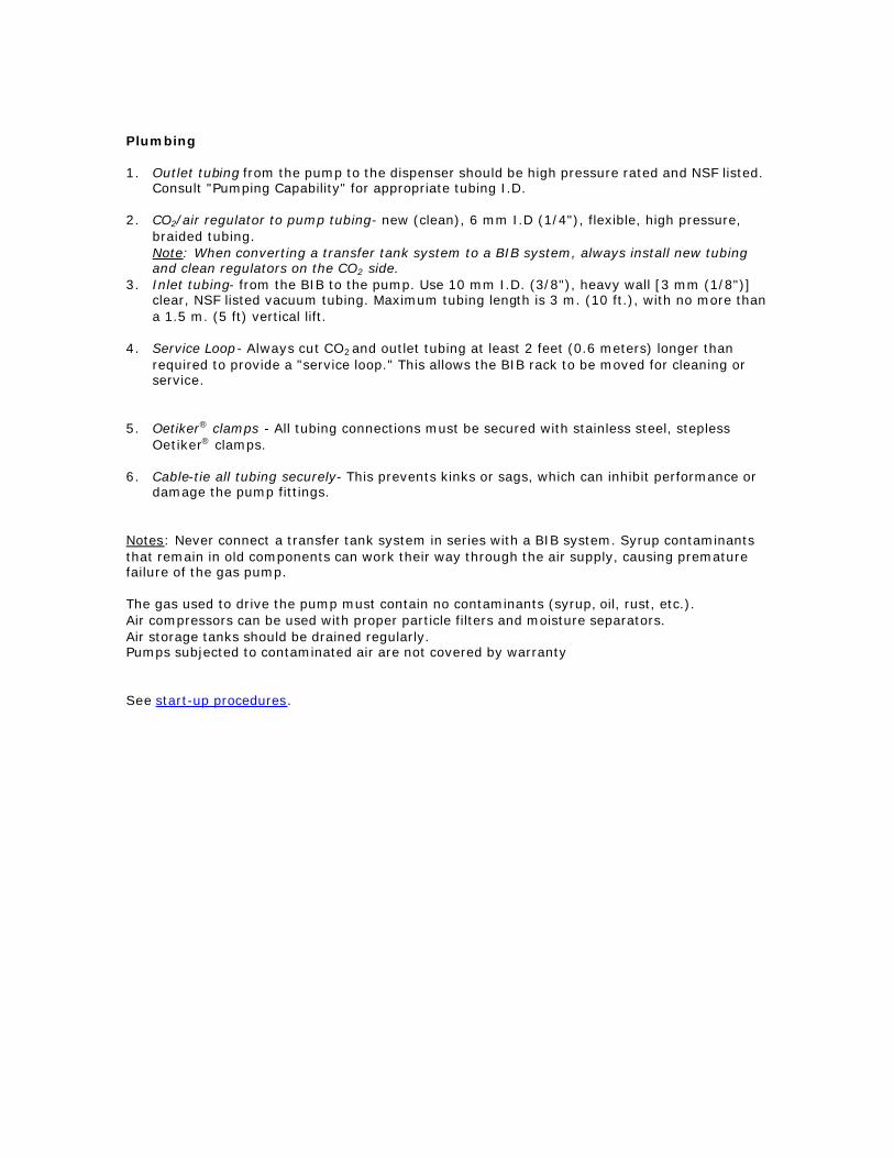
The Juice pump features the same legendary performance and reliability, which has made our gas powered syrup pumps the standard of the beverage industry.
The Juice pump utilizes a modified valve design to allow the pumping of products containing soft solids classed as round (up to 0.025" or 0.6 mm.) or for concentrates that are higher viscosity than soda syrups (bloody mary and margarita mix, etc).
Technical Specifications
Design Two Chamber Double Diaphragm
Power Source CO2 gas, Nitrogen or Clean Compressed Air
Materials of Construction Polypropylene, EPDM, Santoprene, 316 Stainless Steel Temperature Limits 34° - 120°F (1.1° - 49°C)
Weight 2 lbs. (0.9 kg.)
Size 7.9" H x 5.7" W x 3.8" D (171 mm x 145 mm x 97 mm)
Displacement 2.5 oz. (74 cc) / cycle
Suction Lift Activated @ 20 in. Hg. (508 m bar), wet 25 in. Hg. (847 m bar)
Maximum Operating Pressure
70 psi (4.7 bar)
Minimum Operating Pressure
20 psi (1.4 bar)
Liquid Fittings 3/8" barb nylon or 1/4", 3/8" or 1/2" barb Stainless steel
Air Fittings 1/4" barb plastic or barb brass w/check valve
SHURflo BIB gas pump is approved by all leading soft drink manufacturers and is NSF and SK approved for water, alcoholic, nonalcoholic beverages and condiments. Operations Manual

Heavy Duty Advantage Condiment Pump
The Condiment pump features the same legendary performance and reliability, which has made our gas powered syrup pumps the standard of the beverage industry. The straight-through flow path offers less restriction, allowing more viscous and particulates to be pumped. Pump valves have been modified using custom designed materials compatible with all aggressive concentrates, including cranberry juice. The particulate valve will allow particles up to 1/4" (6 mm.) cubed, assuring fewer restrictions than other pumps on the market.
Condiment Valve
Technical Specifications
Design Two Chamber Double Diaphragm
Power Source CO2 gas, Nitrogen or Clean Compressed Air
Materials of Construction Polypropylene, EPDM, Santoprene, 316 Stainless Steel Temperature Limits 34° - 120°F (1.1° - 49°C)
Weight 2 lbs. (0.9 kg.)
Size 7.9" H x 5.7" W x 3.8" D (171 mm x 145 mm x 97 mm)
Displacement 2.5 oz. (74 cc) / cycle
Suction Lift Activated @ 20 in. Hg. (508 m bar), wet 25 in. Hg. (847 m bar)
Maximum Operating Pressure
70 psi (4.7 bar)
Minimum Operating Pressure
20 psi (1.4 bar)
Liquid Fittings 3/8" barb nylon or 1/4", 3/8" or 1/2" barb Stainless steel
Air Fittings 1/4" barb plastic or barb brass w/check valve
The SHURflo BIB gas pump is approved by all leading soft drink manufacturers and is NSF and SK approved for water, alcoholic, nonalcoholic beverages and condiments. Operations Manual.

Recommended Gas Pump Model Numbers
Model Description Liq Out Liq In Gas In Gas Out
Mounting Plate
94-360-05 Blue H.D.A. Condiment pump
3/8” SS barb elbow
3/8” plastic barb elbow
1/4” plastic barb elbow w/check valve
none yes
94-360-00 Blue H.D.A. syrup pump
1/4” SS barb elbow
3/8” plastic barb elbow
1/4” plastic barb elbow w/check valve
none yes
94-360-41 Blue H.D.A. syrup pump
3/8” SS barb elbow
3/8” plastic barb elbow
1/4” plastic barb Tee w/check valve
none yes
94-366-51 Blue High Altitude H.D.A. syrup pump
3/8” SS barb elbow
3/8” plastic barb elbow
1/4” plastic barb elbow w/check valve
none yes
94-360-05 Black H.D.A. Juice pump
3/8” plastic barb elbow
3/8” plastic barb elbow
1/4” plastic barb elbow w/check valve
none yes
94-360-12 Black H.D.A. Condiment pump
1/2” plastic barb elbow
1/2” plastic barb elbow
1/4” plastic barb elbow w/check valve
none yes
94-360-15 Black H.D.A. Condiment pump
3/8” plastic barb elbow
3/8” plastic barb elbow
1/4” plastic barb elbow w/check valve
none yes

Gas Pump Installation
Considerations When designing a BIB system, take the following points in consideration to ensure long-term operation of the pump and maximizing space efficiency. 1. How many pumps?
There should be one pump per flavor. More pumps may be needed based on the total flow requirements for each flavor.
2. Where to mount? Each pump is equipped with a mounting bracket and can be mounted in the following ways: - Wall mount - Space efficient; maximizes vertical space. - Top mounting bar - Space e fficient; easy to relocate and can be pre -assembled. - Side of rack - Uses more horizontal space; may shorten distance from BIB to pump.
3. Location of pump/BIBs - Low traffic areas - A key benefit of SHURflo BIB pumps is distance pumping capability. This allows the BIB system to be located out of the employee high traffic areas and in a more strategic location. - Away from high heat - heat can distort the plastic parts of the pump and shorten the shelf life of the syrup. If high heat is a factor in where the pumps are to be located, the pumps need to be shielded from the heat. If at all possible it would be better to locate the pumps in a different location. - Outside walk-in cooler- moisture can collect in the control cover and swell poppet seals causing the pump to fail. The cooler temperature causes the viscosity of the product to increase making the pump to work harder to move the same amount of syrup. - In ventilated areas only - high concentrations of CO2 can be fatal, since it will displace oxygen from non-ventilated areas. If CO2 operated BIB pumps are placed in a confined area (such as a basement, closet, cooler box, etc.), exhaust fans capable of changing the room air on a continuous basis should be used. Another option is to manifold the exhaust ports to the outside.
Guidelines 1. Mount pump with outlet on top at higher or
same level as BIB This allows any air on the BIB (inlet) side of the pump to float up to the pump and pass through the system. Creating an installation which avoids trapping air, preventing service calls.
2. Inlet Side - Use only 3/8" I.D. (10mm) Tygon
or equivalent tubing with a minimum of 1/8" (3.2mm) inch wall. Due to the limited vacuum the maximum inlet tubing length is 10 ft. (3m). Within that distance, a maximum of 5 ft. (1.5 m) vertical lift is permitted. (Note: When an ASV is used, the maximum vertical lift will be reduced to 3 ft. (1 m).)
3. Label all lines and pumps. To ensure proper
delivery of syrup to the dispenser, all lines should be tied-down using tie-wraps in their proper location and clearly labeled. Attention to detail will prevent accidental mixing of the flavors during BIB changes and will also facilitate future servicing.
Plumbing 1. Outlet tubing from the pump to the dispenser should be high pressure rated and NSF listed.
Consult "Pumping Capability" for appropriate tubing I.D. 2. CO2/air regulator to pump tubing- new (clean), 6 mm I.D (1/4"), flexible, high pressure,
braided tubing. Note: When converting a transfer tank system to a BIB system, always install new tubing and clean regulators on the CO2 side.
3. Inlet tubing- from the BIB to the pump. Use 10 mm I.D. (3/8"), heavy wall [3 mm (1/8")] clear, NSF listed vacuum tubing. Maximum tubing length is 3 m. (10 ft.), with no more than a 1.5 m. (5 ft) vertical lift.
4. Service Loop- Always cut CO2 and outlet tubing at least 2 feet (0.6 meters) longer than
required to provide a "service loop." This allows the BIB rack to be moved for cleaning or service.
5. Oetiker® clamps - All tubing connections must be secured with stainless steel, stepless
Oetiker® clamps. 6. Cable-tie all tubing securely- This prevents kinks or sags, which can inhibit performance or
damage the pump fittings. Notes: Never connect a transfer tank system in series with a BIB system. Syrup contaminants that remain in old components can work their way through the air supply, causing premature failure of the gas pump. The gas used to drive the pump must contain no contaminants (syrup, oil, rust, etc.). Air compressors can be used with proper particle filters and moisture separators. Air storage tanks should be drained regularly. Pumps subjected to contaminated air are not covered by warranty See start-up procedures.

Start-Up Procedure
1. Confirm that all tubing connections are properly clamped, fittings are tight, and tubing is not kinked.
2. Fully engage BIB connector to insure proper syrup flow. 3. Adjust gas regulator to 1.4 bar (20 psi), allowing the pump to stroke slowly. 4. Operate the valve until all air trapped within the tubing has been purged. 5. Set gas pressure and brix. Adjust the gas regulator to the pressure necessary to
maintain the desired brix. The most efficient gas usage occurs at 2.8 bar (40 psi). Maximum static gas pressure to the pump is 5.8 bar (85 psi); minimum is 1.4 bar (20 psi). Any time the pressure is changed on the BIB system, the brix should be checked to ensure drink quality.
(Notes: Flow rates that result in a stroke-rate of more than two strokes per second will decrease pump life. (Consult factory.) Pump failure due to "overrunning" is not covered by the limited warranty.
To prevent air from entering the system, always leave the bag connector attached to the empty BIB until a new BIB can be installed. Air entering into the system via air in the bags or vacuum leaks can cause brix fluctuation, foaming, spitting, non-operation of the vacuum sold-out or pump "run-on" with the valve closed.).

Trouble-shooting
Although the BIB system is designed to be maintenance -free, on rare occasions there will be problems with the system. In most cases, it will be associated with one of the four following areas:
1. Vacuum leaks/air in the system. Leaks that occur between the BIB and inlet of pump. 2. Syrup leaks. Usually occur at the pump or at the outlet line between the pump and the dispenser. 3. Gas Leaks. Usually occur between the CO2 cylinder and the pump or from air in the BIB. 4. Stalls. May be due to over pressurization. Ensure proper gas pressure and proper regulator
operation. The table below outlines fault conditions and a list to check for possible causes. Condition Check the following Pump does not operate with gas applied (dispenser valve open)
• BIB empty. • Inlet tubing pinched thus activating "sold-out" feature of pump. • Gas regulator over-pressurizing. • Outlet tube kinked or restricted. • Operated without fluid for excessive period. (Dry run) • Transfer tube and gas lines contaminated (syrup, rust, oil, etc.)
Ensure clean gas supply, change out all contaminated. • Internal damage of control cover
Pump operates but will not prime (dispenser valve open)
Consult Start-up Procedure for proper priming • Pump valves have no moisture/dry. Add water to the inlet port with pump stroking slowly. • Vacuum leaks at Q.D., barb fitting clamps, or inlet fitting o-ring. • Debris in valve seats or warped/swollen valves
Pump does not achieve Sold-out with empty BIB
• Vacuum leaks at Q.D., barb fitting clamps, or inlet fitting o-ring • Excessive amount of air in BIB from improper packaging. • Air trapped in outlet tubing and/or fluid chambers.
Air in inlet or outlet tubing
• Vacuum leaks at Q.D. o-ring or barb fitting clamps • Vacuum leaks at inlet fitting; o-ring pinched or missing. • Large amounts of air noticed only in the outlet tubing when
pump operates. Diaphragm/piston assemblies ruptured. Pump strokes with dispenser valve closed
• Air trapped in outlet tubing and/or fluid chambers. Open outlet and purge air, check for vacuum leaks, or air in BIB • Debris in outlet valves or warped/swollen valves.
Fluid from exhaust or visible within the gas inlet tubing
• Carbonator check valve • Ensure clean gas supply • Diaphragm/piston assemblies ruptured change out all contaminated pumps
Gas blowing from exhaust continuously
• Control cover subjected to contaminated gas supply or damaged.
Ensure clean gas supply, change out all contaminated pumps

Calculating Maximum Pumping Distance
1. Obtain the maximum horizontal tubing length (L ) from Tables. 2. Take 3% of the maximum horizontal tubing length (L) in meters and multiply the result
by the vertical distance (Lvert): C = 0.03 x (L) x (L vert)
3. Subtract this product (C) from the maximum horizontal tubing length (L) to obtain the maximum pumping distance (Lmax) in consideration of the specific vertical lift:
Lmax = L - C
Note: The result is the maximum pumping distance (Lmax), including horizontal and vertical tubing runs, that is obtainable for the particular flow rate, tubing I.D. and viscosity of syrup specified. To calculate the losses in the system in feet obtained the maximum horizontal tubing length in feet and multiply by 1% instead of 3%.
Example 1. The tables indicate that heavy soda syrup with 15 ml/sec (1/2 oz./sec) flow-rate (per
the example above) can be sustained over a horizontal distance of 152m (500 ft.) when 10 mm I.D. (3/8") tubing is used. Therefore; L = 152 m.
2. C = (0.03 x 152) x 6.7m = 121.5 m 3. Lmax = 152 - 30.5 m = 121.5 m; Lmax = 121.5m The results indicate a 121.5m tubing length (horz./vert.) is possible, while the example only requires a distance of 113m. Note: If the example above resulted in a value that was equal to or less than the necessary total tubing run, the installer would need to consider a larger I.D. tubing or installation of a pump(s) in series using the SHURflo Vacuum Regulator.
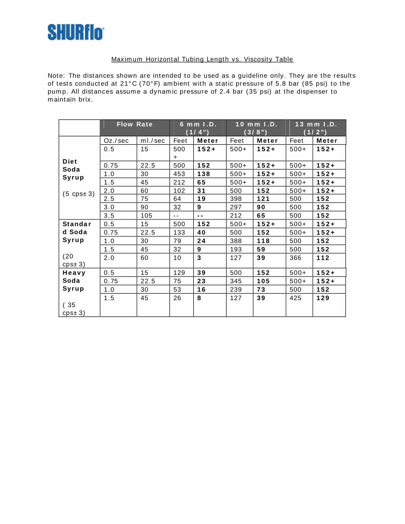
Maximum Horizontal Tubing Length vs. Viscosity Table
Note: The distances shown are intended to be used as a guideline only. They are the results of tests conducted at 21°C (70°F) ambient with a static pressure of 5.8 bar (85 psi) to the pump. All distances assume a dynamic pressure of 2.4 bar (35 psi) at the dispenser to maintain brix.
Flow Rate 6 mm I.D. (1/4”)
10 mm I.D. (3/8”)
13 mm I.D. (1/2”)
Oz./sec ml./sec Feet Meter Feet Meter Feet Meter 0.5 15 500
+ 152+ 500+ 152+ 500+ 152+
0.75 22.5 500 152 500+ 152+ 500+ 152+ 1.0 30 453 138 500+ 152+ 500+ 152+ 1.5 45 212 65 500+ 152+ 500+ 152+ 2.0 60 102 31 500 152 500+ 152+ 2.5 75 64 19 398 121 500 152 3.0 90 32 9 297 90 500 152
Diet Soda Syrup (5 cps±3)
3.5 105 -- -- 212 65 500 152 0.5 15 500 152 500+ 152+ 500+ 152+ 0.75 22.5 133 40 500 152 500+ 152+ 1.0 30 79 24 388 118 500 152 1.5 45 32 9 193 59 500 152
Standard Soda Syrup (20 cps±3)
2.0 60 10 3 127 39 366 112
0.5 15 129 39 500 152 500+ 152+ 0.75 22.5 75 23 345 105 500+ 152+ 1.0 30 53 16 239 73 500 152
Heavy Soda Syrup ( 35 cps±3)
1.5 45 26 8 127 39 425 129

BEVERAGE GAS PUMP 166-296-XX Installation and Operation Manual SHURflo’s Beverage Gas Pump supplies syrup under pressure to a post-mix dispenser, which mixes the syrup with water to an exact ratio (brix). The pump is used in conjunction with non-pressurized Bag-In-Box (B-I-B) containers and a bag connector (Q.D.) fitting. The pump can be operated on regulated CO2, nitrogen or compressed filtered air. The compressed gas drives the pump and is not in contact with the syrup. Separate syrup and gas chambers prevent contamination, foaming and purging of the outlet tubing when the B-I-B has emptied. The pump retains pressure in the outlet line, operating only when syrup is needed. When the dispenser valve is opened, the pump reacts to the pressure drop by operating to maintain pressure in the line. When the dispenser is closed, the incoming gas and output syrup pressures equalize and the pump stops. Actual dynamic line pressure is dependent upon system losses as outlined in the section "Pumping Capability". The automatic "sold-out" feature within the pump ensures consistent syrup delivery right up to the moment the B-I-B is empty. Vacuum produced by the pump evacuates the syrup within the bag. Once the preset vacuum point is achieved and held, incoming gas pressure to the pump is shutoff causing the outlet syrup pressure to drop to zero. When a new B-I-B is installed, the vacuum drops, the pump automatically restarts and pressurizes the system. The SHURflo Beverage Gas Pump ensures quality from the first drink to the last.
APPLICATION INFORMATION Beverage Gas Pumps are intended for soda syrups and low viscosity concentrates that do not contain solids. The use of a SHURflo Juice Pump (-09) is recommended for concentrates containing soft solids, classed as round, up to 0.025 in. [0.6 mm] or that are of higher viscosity than soda syrups. When concentrates contain pulp classed as long/stringy, seed particles or are exceptionally viscous the Particulate Juice Pump (-10) should be used as it can handle soft solids up to 1/4" [6 mm] cube.
PUMPING CAPABILITY Beverage dispensing systems have inherent factors that affect the distance syrup can be delivered. Restrictions within the B-I-B system’s inlet/outlet will limit pumping capability. Due to variances in system configuration and equipment, an accurate determination of pressure drop is difficult. Before deciding on a system’s tubing size, SHURflo recommends estimating system losses by considering the following: • Syrup viscosity and temperature (coldplate, re-circ., etc.). • Total syrup flow rate of valve(s) connected to a pump. • Inside diameter of the inlet/outlet tubing, fittings, etc. • Horizontal & vertical distance of the outlet tubing. Vertical tubing runs will reduce total tubing run length. To estimate the losses within the vertical distance, use the chart to the right. Take 1% of the distance in feet [3% if meters]. The resulting number is multiplied by the vertical distance. This product is then subtracted from the maximum horizontal distance. The resulting length is the total horizontal/vertical (horz./vert.) tubing run that is obtainable for that flow rate, tubing I.D. and viscosity.
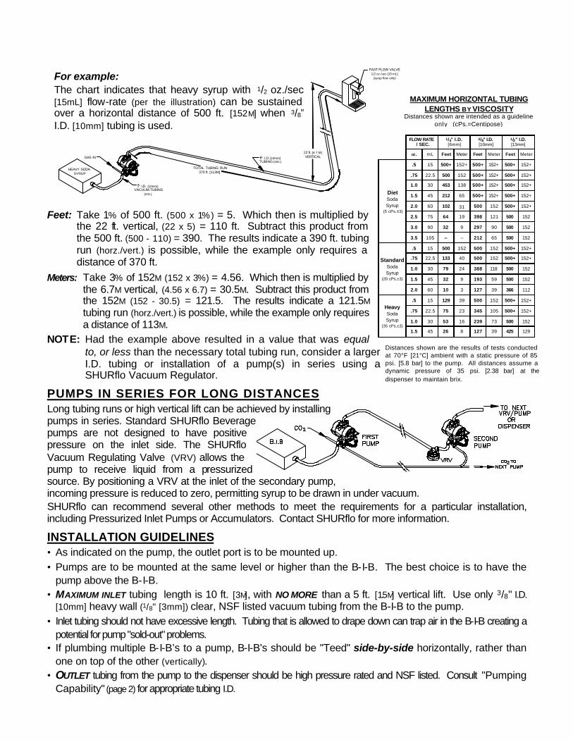
MAXIMUM HORIZONTAL TUBING LENGTHS BY VISCOSITY
Distances shown are intended as a guideline only. (cPs.=Centipose)
Distances shown are the results of tests conducted at 70°F [21°C] ambient with a static pressure of 85 psi. [5.8 bar] to the pump. All distances assume a dynamic pressure of 35 psi. [2.38 bar] at the dispenser to maintain brix.
38 " I.D. [10mm]
HEAVY SODASYRUP
GAS IN
VACUUM TUBING (min.)
38 " I.D. [10mm]TUBING (min.)
22 ft. [6.7 M]VERTICAL
FAST FLOW VALVE1/2 oz./sec [15 mL]
(syrup flow only)
TOTAL TUBING RUN370 ft. [113M]
Feet: Take 1% of 500 ft. (500 x 1%) = 5. Which then is multiplied by
the 22 ft. vertical, (22 x 5) = 110 ft. Subtract this product from the 500 ft. (500 - 110) = 390. The results indicate a 390 ft. tubing run (horz./vert.) is possible, while the example only requires a distance of 370 ft.
Meters: Take 3% of 152M (152 x 3%) = 4.56. Which then is multiplied by the 6.7M vertical, (4.56 x 6.7) = 30.5M. Subtract this product from the 152M (152 - 30.5) = 121.5. The results indicate a 121.5M tubing run (horz./vert.) is possible, while the example only requires a distance of 113M.
NOTE: Had the example above resulted in a value that was equal to, or less than the necessary total tubing run, consider a larger I.D. tubing or installation of a pump(s) in series using a SHURflo Vacuum Regulator.
PUMPS IN SERIES FOR LONG DISTANCES Long tubing runs or high vertical lift can be achieved by installing pumps in series. Standard SHURflo Beverage pumps are not designed to have positive pressure on the inlet side. The SHURflo Vacuum Regulating Valve (VRV) allows the pump to receive liquid from a pressurized source. By positioning a VRV at the inlet of the secondary pump, incoming pressure is reduced to zero, permitting syrup to be drawn in under vacuum. SHURflo can recommend several other methods to meet the requirements for a particular installation, including Pressurized Inlet Pumps or Accumulators. Contact SHURflo for more information.
INSTALLATION GUIDELINES • As indicated on the pump, the outlet port is to be mounted up. • Pumps are to be mounted at the same level or higher than the B-I-B. The best choice is to have the
pump above the B-I-B. • MAXIMUM INLET tubing length is 10 ft. [3 M], with NO MORE than a 5 ft. [1.5 M] vertical lift. Use only 3/8" I.D.
[10mm] heavy wall (1/8" [3mm]) clear, NSF listed vacuum tubing from the B-I-B to the pump. • Inlet tubing should not have excessive length. Tubing that is allowed to drape down can trap air in the B-I-B creating a
potential for pump "sold-out" problems. • If plumbing multiple B-I-B’s to a pump, B-I-B's should be "Teed" side-by-side horizontally, rather than
one on top of the other (vertically). • OUTLET tubing from the pump to the dispenser should be high pressure rated and NSF listed. Consult "Pumping
Capability" (page 2) for appropriate tubing I.D.
FLOW RATE / SEC.
1/4" I.D.[6mm]
3/8" I.D.[10mm]
1/2" I.D.[13mm]
OZ. mL Feet Meter Feet Meter Feet Meter
DietSodaSyrup
(5 cPs.±3)
.5 15 500+ 152+ 500+ 152+ 500+ 152+
.75 22.5 500 152 500+ 152+ 500+ 152+
1.0 30 453 138 500+ 152+ 500+ 152+
1.5 45 212 65 500+ 152+ 500+ 152+
2.0 60 102 31 500 152 500+ 152+
2.5 75 64 19 398 121 500 152
3.0 90 32 9 297 90 500 152
3.5 105 -- -- 212 65 500 152
StandardSodaSyrup
(20 cPs.±3)
.5 15 500 152 500 152 500+ 152+
.75 22.5 133 40 500 152 500+ 152+
1.0 30 79 24 388 118 500 152
1.5 45 32 9 193 59 500 152
2.0 60 10 3 127 39 366 112
HeavySodaSyrup
(35 cPs.±3)
.5 15 129 39 500 152 500+ 152+
.75 22.5 75 23 345 105 500+ 152+
1.0 30 53 16 239 73 500 152
1.5 45 26 8 127 39 425 129
For example: The chart indicates that heavy syrup with 1/2 oz./sec [15mL] flow-rate (per the illustration) can be sustained over a horizontal distance of 500 ft. [152M] when 3/8" I.D. [10mm] tubing is used.

REMOVE
FORCE
• Always cut CO2 and outlet tubing at least 2 ft. [.6 M] longer to provide a "service loop" so the B-I-B rack can be moved for cleaning or service.
• Use new (clean), 1/4" I.D. [6mm], flexible, high pressure, braided tubing from the CO2 / air regulator to the pump.
NOTE: NEVER connect a transfer tank "system" in series with a B-I-B system. Syrup contaminants in old components may work their way through the air supply causing premature failure of the gas pump. The gas used to drive the pump MUST be clean and contain no contaminants (syrup, oil, rust, water, etc). Air compressors may be used with proper particle filters and moisture separators. Air storage tanks should be drained regularly. Pumps subjected to contaminated air are not covered by warranty.
WARNING: High concentrations of CO2 can be fatal as it will displace the air from non-ventilated areas. Pumps operated by CO2 must be in ventilated areas. If placed in a confined area (basement, closet, cooler box, etc.), exhaust fans capable of changing the room air on a continuous basis should be used.
• All tubing connections must be secured with stainless steel, stepless Oetiker® clamps. • Cable-tie all tubing securely to prevent kinks or sags that inhibit performance or cause damage to the
pump fittings.
START-UP PROCEDURE 1. Confirm that all tubing connections are properly clamped, fittings are tight, and tubing is not kinked.
Install bag connector to the B-I-B. 2. Adjust gas regulator to about 20 psi. [1.4 bar] allowing the pump to stroke slowly. 3. Operate the valve until all air trapped within the tubing has been purged. 4. Once the air has been purged, adjust the CO2 regulator to the pressure necessary to maintain the
desired brix. The most efficient gas usage occurs at 40 psi. [2.8 bar]. MAXIMUM static gas pressure to the pump is 85 psi. [5.8 bar], minimum 20 psi. [1.4 bar].
CAUTION: Flowrates that result in a stroke-rate of more than two strokes per second will decrease pump life. (Consult factory) Pump failure due to "overrunning" is not covered by the limited warranty.
NOTE: To prevent air from entering the system always leave the bag connector attached to the empty B-I-B until a new B-I-B can be installed. Air entered into the system, via air in the bags or vacuum leaks, may cause brix fluctuation, foaming, spitting, non-operation of the vacuum sold-out or pump "run-on" with the valve closed. Symptoms of this kind can lead to a misdiagnosis of the pump.
MOUNTING CLIP KNOCKOUT REMOVAL Removal of the knockout tabs from the pump housing is only necessary if the pump will be installed onto a SHURflo Mounting Board. Depending on board style, spring clip orientation varies. Ensure spring clip position and corresponding knockout tabs before removal. NOTE: The knockout tabs must not be pushed into the housing cavity. Failure to
remove the tab from the housing will cause the spring clips not to engage completely, making the mounting insecure.
1. Position the pump on its side, in a secure location where the pump can be held firmly.
2. Place an appropriate sized flat blade screwdriver into the indentation as shown. NOTE: Breaking the tabs at this particular indentation facilitates complete tab removal. 3. Break the tabs loose by either pressing firmly, or striking the screwdriver handle solidly with
your palm. 4. The tab should break away from the housing, allowing it to be popped-out with the screwdriver. Removal of the aluminum mounting bracket may be required to permit full engagement of the spring clips. Screw torque 15-18 in/Lb. [17-20 N•m]
SOS
ASV
PUMP SANITIZING / WINTERIZING Sanitization of the SHURflo Beverage Gas Pump is required. The frequency of Sanitization is dependent on the concentrate type and its manufacturer’s requirements. Factors, which also affect the frequency of this procedure, are: temperature, concentrate volatility, facility conditions, installation and equipment. The sanitizing procedure fulfills a required 10 minute contact time with a 200 ppm Sodium Hyochlorite solution. Refer to SHURflo Service Bulletin #1025 for the N.S.F. listed sanitizing procedure for the SHURflo pump only Pumps that are subjected to freezing (below 32° F [0°C]) must be purged of fluid to prevent damage. Refer to SHURflo Service Bulletin #1025 for complete winterizing procedure. Refer to the equipment manufacturer’s instructions for sanitizing and winterizing procedure for carbonators, dispensers and tubing. NOTE: Pumps that have been winterized and/or out of service for a period of time should be sanitized
prior to being placed back in service. CAUTION: Never apply pressure to the pump’s liquid inlet. Pressurized tanks may damage internal
components if used to sanitize or purge fluid from the pump (operating or not).
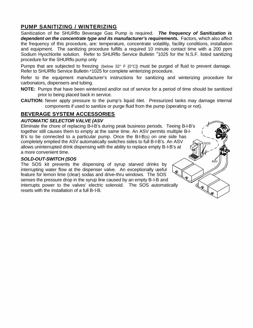
BEVERAGE SYSTEM ACCESSORIES AUTOMATIC SELECTOR VALVE (ASV Eliminate the chore of replacing B-I-B’s during peak business periods. Teeing B-I-B’s together still causes them to empty at the same time. An ASV permits multiple B-I-B’s to be connected to a particular pump. Once the B-I-B(s) on one side has completely emptied the ASV automatically switches sides to full B-I-B’s. An ASV allows uninterrupted drink dispensing with the ability to replace empty B-I-B’s at a more convenient time. SOLD-OUT-SWITCH (SOS The SOS kit prevents the dispensing of syrup starved drinks by interrupting water flow at the dispenser valve. An exceptionally useful feature for lemon lime (clear) sodas and drive-thru windows. The SOS senses the pressure drop in the syrup line caused by an empty B-I-B and interrupts power to the valves’ electric solenoid. The SOS automatically resets with the installation of a full B-I-B.

TROUBLESHOOTING DOES NOT OPERATE / GAS APPLIED / DISPENSER VALVE OPEN ü B-I-B empty or inlet tubing pinched off activating vacuum "sold-out" ü Gas regulator over-pressurizing ü Outlet tube kinked or restricted ü Operated without fluid for excessive period. (Dry run) ü Transfer tube and gas lines contaminated (syrup, rust, oil, etc
[ensure clean gas supply, change out all contaminated ü Internal damage of control cover
OPERATES BUT WILL NOT PRIME / DISPENSER VALVE OPEN [consult Start-up Procedure for proper priming].
ü Pump valves have no moisture/dry. [add water to the inlet port with pump stroking slowly.
ü Vacuum leaks at Q.D., barb fitting clamps, or inlet fitting o-ring. ü Debris in valve seats or warped/swollen valves.
DOSE NOT ACHIEVE SOLD-OUT WITH EMPTY B-I-B ü Vacuum leaks at Q.D., barb fitting clamps, or inlet fitting o-ring ü Excessive amount of air in B-I-B from improper packaging. ü Air trapped in outlet tubing and/or fluid chambers.
AIR IN INLET AND/OR OUTLET TUBING ü Vacuum leaks at Q.D. o-ring or barb fitting clamps ü Vacuum leaks at inlet fitting; o-ring pinched or missing. ü Large amounts of air noticed only in the outlet tubing when pump operates
[diaphragm/piston assemblies ruptured]
STROKES WITH DISPENSER VALVE CLOSED ü Air trapped in outlet tubing and/or fluid chambers.
[open outlet and purge air, check for vacuum leaks, or air in B-I-B ü Debris in outlet valves or warped/swollen valves.
FLUID FROM EXHAUST OR VISIBLE WITHIN GAS INLET TUBING ü Carbonator check valve ü üEnsure clean gas supply ü Diaphragm/piston assemblies ruptured [change out all contaminated pumps GAS BLOWING FROM EXHAUST CONTINUOUSLY ü Control cover subjected to contaminated gas supply or damaged
[ensure clean gas supply, change out all contaminated pumps]

LIMITED WARRANTY SHURflo warrants new Beverage Gas Pumps to be free from material and workmanship defects (under normal use and service) for a period of three (3) years from the date of manufacture. An additional 30 days may be added to allow for storage and transit delays. In any event, the total limited warranty period will not exceed thirty-seven (37) months from date of manufacture. The limited warranty will not apply to pumps that were improperly installed, misapplied, or not suitable with components of other manufacturers. The limited warranty will not apply to pumps subjected to fluids that are incompatible with pump materials, or pumps operated by a contaminated air supply. SHURflo will not warrant any pump that is physically damaged or modified outside the SHURflo factory. All SHURflo gas pumps should be returned to the authorized distributor where they were purchased. SHURflo's obligation under this warranty policy is limited to repair or replacement. Pumps found not defective (under the terms of this limited warranty) are subject to charges to be paid by the returnee for the testing and packaging of "sanitized & tested good" units. No credit or labor allowances will be given to the returnee for pumps returned as defective. Warranty replacements will be shipped on a freight allowed basis. SHURflo reserves the right to choose the method of transportation. This limited warranty is in lieu of all other warranties, expressed or implied, and no other person is authorized to give any other warranty or assume obligation or liability on SHURflo's behalf. SHURflo shall not be liable for any labor, damage or other expense, nor shall SHURflo be liable for any indirect, incidental or consequential damages of any kind incurred by the reason of the use or sale of any defective product or part. This limited warranty covers beverage products distributed within the United States of America. Other countries should consult with the distributor for any deviation from this document.
TECHNICAL SPECIFICATIONS DESIGN: Twin Chamber Double Diaphragm MATERIALS OF CONSTRUCTION: Polypropylene, EDPM, Santoprene, 300 Stainless Steel,
FDA sanctioned, NSF Listed, CE, S-K POWER SOURCE: CO2, Nitrogen, or compressed filtered air OPERATING PRESSURE: 20 psi. MIN. [1.4 bar] / 85 psi. MAX. [5.8 bar] static MAXIMUM STROKE RATE: 2 strokes /sec; intermittent duty (consult factory) DISPLACEMENT: 3.4 oz. per cycle [101 cc] AUTOMATIC SOLD-OUT: 20–24"Hg. [68–81kPa] activation (wet). No reset required. TEMPERATURE LIMITS: 34° – 120°F [1.1° – 49°C] WEIGHT: 1 lb. [.45 kg] AVAILABLE* LIQUID FITTINGS: 1/4" [6mm], 3/8" [10mm], and 1/2" [13mm] barb elbows, straights; and 90°
configurations; plastic or stainless. John Guest® straight tube; plastic.
AVAILABLE* CO2 / AIR / EXHAUST FITTINGS:
*Pump assembly part number determines fitting configuration.
Metric fittings dimensions are approximation to U.S. inch size.
1/4" [6mm] barb elbows or "T"s; plastic or brass; with internal check valve. 1/4" [6mm] barb elbows or straights; plastic (no c/valve). John Guest® straight tube; plastic (no c/valve). Muffler assembly
« ISO Certified Facility
R
a WICOR Company SHURflo reserves the right to update specifications, prices, or make substitutions.
SHURflo « 5900 Katella Ave.
Cypress, CA 90630 (800) 854-3218 (562) 795-5200
FAX (562) 795-7564 Shipping/UPS: 5900 Katella Ave., Suite B
SHURflo East 52748 Park Six Court
Elkhart, IN 46514-5427 ((800) 762-8094 (219) 262-0478
FAX (219) 264-2169
SHURflo Ltd. Unit 5 Sterling Park
Gatwick Road, Crawley West Sussex, RH10 2QT
United Kingdom +44 1293 424000
FAX +44 1293 421880

911-437 Rev. F 1/98 Page: 1 of 6
JUICE GAS PUMP 166-200-XX (GREEN LABEL)
Installation and Operation ManualThe SHURflo model #166-200-09 (Standard Juice pump) is for concentrates that contain soft solids classedas "round" (up to .025 in. dia.[.6mm]) or for concentrates that are of higher viscosity than soda syrups.Model #166-200-10 (Particulate Juice pump) is designed to transfer concentrates that contain, pulpclassed as long/string, seed particles, or soft solids up to ¼" [6mm] cube. It is also recommend forconcentrates that are extremely viscous. The pumps valve cartridges minimize the collection ofparticulates and promotes thorough flushing during sanitization.Both models of the Juice pump are compatible with concentrates that are highly acidic (low pH value),and are identified by black inlet and outlet fittings.Juice concentrates are generally supplied in flexible plastic bags, packaged inside cardboard boxes(Bag-In-Box). Juice concentrates generally require more frequent sanitization. The manufacturer of theconcentrate should specify the interval for sanitizing; however, other factors such as systemconfiguration, and/or temperature may affect concentrate life. (see page: 4)
The Juice pump pressurizes the concentrate to match the pressure of the gas supply. The pump can beoperated on regulated CO2, nitrogen, or clean compressed air. The compressed gas is used to operatethe pump and does not come in contact with the concentrate. The pump operates when concentrate isneeded, which is termed as its "automatic demand" feature. When the post-mix dispenser valve isopened, the pump reacts to the drop in pressure by operating to maintain pressure in the line. When thedispensing valve is closed, the input gas and output concentrate pressures equalize and the pumpstops. As the B-I-B empties, the pump draws a vacuum collapsing the bag evacuating it of concentrate.The pump automatically shuts off once vacuum above 20 in/Hg. [508 mm/Hg.] is obtained. When a newB-I-B is connected the vacuum drops, the pump automatically resumes pumping.
PUMPING CAPABILITYDue to diversity of both the installations and equipment used within beverage systems, it is difficult tocalculate/predict total pumping distance. The ability to deliver fluid is limited by the dynamics of the fluid (flow)and pump displacement at pressure. Consider all the following factors when estimating pressure drop withina beverage system.
• Fluid viscosity (Centipose/cP.) @ temperature. • Inside diameter of the inlet/outlet tubing, fittings, etc.
• Horizontal distance of the outlet tubing. • Total syrup flow rate of valve(s) supplied by a given pump.
• The pressure drop per foot within vertical tubing runs is significant. To estimate the losses use theappropriate distance given by Max. Horz. Dist. Chart (page: 2). Take 1% of that distance [3% if meters].Multiply the vertical distance by that number. Subtract the product from the original Max. Horz. distance.The result is the total tubing run (includes vertical) that should be attempted for that flow rate, tubing I.D.,and viscosity.
Example: The facility requires a total tubing run of 196 ft.[60M]; included that run is a 14 ft.[4.26M] vertical.The product is 100% Grape juice dispensed by one fast flow valve (.5 oz/sec.[14.8 cc/sec])The distance chart indicates 248 ft. [76 M] (50-100 cP @ .5 oz/sec) with 3/8" I.D.[10mm] tubing.
1% of 248 is 2.48, which is then multiplied by 14 ft, equaling approximately 35 ft. Subtracted that productfrom the 248 ft. (248–35 = 213). 213 ft. is the total tubing run that can be achieved including the 14 ft. vertical.To calculate the vertical losses for distances measured in meters, take 3% of the distance given [76 M] =2.28. Multiply by the vertical meters (2.28 x 4.26 = 9.7). Subtract that product (76–9.7 = 66.3). 66.3meters is the total tubing run that can be achieved including the 4.26 M vertical.
NOTE: Had the example above resulted in a value that was equal to, or less than the necessary total tubingrun, consider a larger I.D. tubing or installation of a pump(s) in series using a vacuum regulator.

Page: 2 of 6
MAXIMUM HORIZONTAL DISTANCE by VISCOSITY (cP)THE FOLLOWING TABLES ARE TO BE USED AS A GUIDELINE ONLY
*20-50 (cP) FLOW RATE 1/4" [6mm] I.D. TUBING 3/8" [10mm] I.D. TUBING
50% Apple 5:1 .0Z /SEC. CC /SEC. FEET METER FEET METER100% Apple 4:1 .25 7.4 272 83 500 152Fruit Punch 5:1 .5 14.8 150 42 450 137Lemonade 5:1 .75 22.2 101 31 303 92
Pink Lemonade 5:1 1.0 29.6 50 15 153 47Lemon lime Soda 5:1 1.25 37.0 - - - - 110 34
Typ. Heavy Soda Bev. 5:1 1.5 44.4 - - - - 62 19* For further viscosity charts in this range refer to Standard Gas Pump Manual # 911-293
50-100 (cP) FLOW RATE 3/8" [10mm] I.D. TUBING 1/2" [13mm] I.D. TUBING
50% Grape 5:1 .0Z /SEC. CC /SEC. FEET METER FEET METER100% Grape 5:1 .25 7.4 296 90 394 120Grapefruit 5:1 .5 14.8 248 76 347 106Cranberry 5:1 .75 22.2 205 63 298 91Pineapple 5:1 1.0 29.6 150 47 251 77
1.25 37.0 78 24 206 631.5 44.4 54 16 153 471.75 51.8 - - - - 112 342.0 59.2 - - - - 59 18
100-500 (cP) FLOW RATE 3/8" [10mm] I.D. TUBING 1/2" [13mm] I.D. TUBING
50% O.J. 5:1 .0Z /SEC. CC /SEC. FEET METER FEET METER100% O.J. 4:1 .25 7.4 122 37 246 75
100% O.J. 3.5:1 .5 14.8 104 32 198 60Margarita 4:1 .75 22.2 77 23 153 47Tomato 1.5:1 1.0 29.6 56 17 105 32
1.25 37.0 29 9 50 151.5 44.4 13 4 27 8
500-1000 (cP) FLOW RATE 3/8" [10mm] I.D. TUBING 1/2" [13mm] I.D. TUBING
O.J. (Natural) 3:1 .0Z /SEC. CC /SEC. FEET METER FEET METERTomato 2:1 .25 7.4 56 17 123 37
Bloody Mary 2:1 .5 14.8 32 9.7 100 30Canadian Caesar 2:1 .75 22.2 17 5.2 78 24
1.0 29.6 7 2 52 161.25 37.0 - - - - 27 8
1000-3500 (cP) FLOW RATE 3/8" [10mm] I.D. TUBING 1/2" [13mm] I.D. TUBING
O.J. (Natural) 5:1 .0Z /SEC. CC /SEC. FEET METER FEET METERCaesar 2:1 .25 7.4 49 15 96 29
.5 14.8 27 8 58 18.75 22.2 13 4 32 101.0 29.6 - - - - 18 6
• Values in Bold create an inlet vacuum of 16" Hg. or higher at flow rates shown. Inlet tubing used was 3/8" I.D.[10mm] with a total length of 5 ft, with 3 ft. of vertical lift. Conditions of this kind should use 1/2" [13mm] I.D.vacuum tubing with minimal vertical lift. Fittings such as Liquibox Q.C.D.™ III connector and bag fittment areless restrictive and utilize a larger barb fitting/tubing which can minimize inlet vacuum.
• Product viscosity and solids content will vary, depending upon the manufacture and type of concentrate.• The tables above are the results of test conducted with 70 psi. [4.8 bar] (to the pump), with a minimum of 20 psi.
[1.4 bar] at the dispenser valve (to maintain brix). Ambient temperature was 70°F [20°C].

Page: 3 of 6
INSTALLATION GUIDELINES
• The outlet port/fitting of the pump is mounted vertical, up.
• The pump should be mounted above the B-I-B or at least at the same level. Pumps placed lower thanthe B-I-B’s will increase the ability to entrap air in the B-I-B.
• Use 3/8" or 1/2" I.D. [10 or 13mm] heavy wall (1/8" [3 mm]) clear, NSF listed vacuum tubing from the B-I-B tothe pump inlet.
a) With low viscosity (thin) products (40 cP or less); the maximum length of inlet tubing is 5 ft. [1.5M] withNO MORE than a 3 ft. [.7M] vertical lift.
b) High viscosity (thick) products (over 500 cP); may require 1/2" I.D. [13mm] tubing with minimalvertical lift. In some instances no vertical lift can be achieved, the pump may need to be placedwithin one foot from the B-I-B, and slightly above the center of the B-I-B.
NOTE: High inlet vacuum and/or restrictions can evacuate air suspended in some concentrates causinglow brix or premature operation of the vacuum shut-off.
• Use high pressure, NSF listed, braided tubing from the pump outlet to the dispenser equipment. Use3/8" I.D. [10mm] or 1/2" I.D. [13mm] tubing as necessary.
• Tie-wrap all tubing securely to prevent kinks or sags that inhibit performance or cause damage to thepump fittings.
• Use new 1/4" [6mm], high pressure braided tubing from the secondary CO2 /air regulator to the pump.
NOTE: NEVER connect a transfer tank "system" in series with a B-I-B system. Concentrate/contaminants inold components may work their way through the air supply causing premature failure of the gaspump. The gas used to drive the pump MUST be clean and contain no contaminants (syrup, oil,rust, water, etc.). Air compressors may be used with proper particle filters and moistureseparators. Air storage tanks should be drained weekly. Pumps subjected to contaminated airare not covered by warranty.
CAUTION: Pumps driven with CO2 are to be operated in well-ventilated areas. If used in a confinedarea (basement, closet, cooler box, etc.), exhaust fans capable of changing the room air ona continuous basis should be used.
START-UP PROCEDURE1. Confirm that all tubing connections are properly clamped, fittings are locked, and tubing is not kinked.
2. Connect the bag connector onto the B-I-B fittment. Open the dispenser valve (syrup side)
3. Adjust gas regulator to about 20 psi.[1.4 bar] allowing the pump to stroke slowly. Once the pump isprimed the regulator can be adjusted up. With high viscosity (thick) products (over 500 cP), the pumpshould be primed with a minimum of gas pressure. This prevents the shut-off feature frominterupting pump operation due to high inlet vacuum during priming.
4. Continue to operate the dispenser valve until all the air trapped within the tubing has been purged.
5. Once the air has been purged, adjust the CO2 regulator to the pressure necessary to maintain thedesired brix. The most efficient gas usage occurs at 40 psi. [2.8 bar]. Maximum gas pressure to thepump is 70 psi. [4.8 bar]; minimum 20 psi. [1.4 bar].
NOTE: To prevent air from entering the system always leave the bag connector connected to the emptyB-I-B until a new B-I-B can be installed. Air entered into the system, via air in the bags orvacuum leaks, may cause brix fluctuation, foaming, spitting, non-operation of the vacuum shut-off, or the pump to run while the dispenser is closed. Symptoms of this kind can lead to amisdiagnosis of the pump as the problem.

Page: 4 of 6
PUMP SANITIZINGThe SHURflo Juice pump is only one piece of a beverage dispensing system. Therefore, frequent sanitizationof the pump and ALL equipment in the system is required. Sanitization is dependent on the concentratetype and its' manufacturers requirements. Factors which also affect the frequency of this procedure are,temperature, facility conditions, installation, and equipment. Consult other equipment manufacturer'sinstructions for their sanitizing requirements. Perform the following procedure to assure compliance with NSFlisted sanitizing requirements for the SHURflo Juice pump (only). Ref.: SHURflo Service Bulletin #1025
MATERIALS REQUIRED:• Common household bleach (Sodium Hypochlorite; 5.25%) or equivalent.• Common household non-sudsing liquid detergent, suitable for use in a automatic dish washing machine.• An adapter is needed to hold the bag connector on the syrup inlet (suction) line open. A fitting cut
from an empty B-I-B will serve as the adapter.• A 6 ft. [2 M] length of 1/4" [6 mm] tubing with a SHURflo output fitting. (To serve as the bypass hose)• Two five gallon buckets [19L]
• Measuring cup
SANITIZING PROCEDURE1. Turn OFF CO2 pressure to the pump. Open the dispenser valve to drop the line (outlet) pressure.
a) Remove the liquid outlet fitting from the pump. Install the bypass tube fitting in the outlet port ofthe pump and screw in place.
b) Immerse the bag connector and inlet suction tubing in 2 gallons [7.5L] of warm water (120-180°F[48-82°C]).
2. Turn ON CO2 to the pump (approx. 20 psi. [1.4 bar]), and pump the 2 gallons of warm water throughthe pump to flush out concentrate residue. Turn OFF CO2 pressure to the pump.
3. Prepare 1 gallon [3.8 L] of detergent solution in a clean container. Mix at the ratio of 1 oz. [30 cc] ofdetergent per each gallon of warm water.a) Place the bag connector in the detergent solutionb) Pump approximately 3/4 gallon [2.8 L] of detergent solution through the pump.c) Turn OFF CO2 pressure to the pump. Allow the detergent solution to remain in the pump for a
contact time of two minutes.d) Turn the pump upside down and operate the pump until the remaining detergent solution is
pumped out. Turn OFF CO2 pressure.
4. Repeat steps; 1b) and 2 (i.e.: flush with 2 gallons of warm water.)
5. Prepare 1 gallon [3.8 L] of sanitizing solution (Hypochlorite) in a clean container. Mix at the ratio 1/4 oz[7.5 cc] of bleach per each gallon of water to obtain a mixture of 100 ppm.a) Place the bag connector in sanitizing solution container.b) Pump approximately 3/4 gallon of sanitizing solution through the pump.c) Turn OFF CO2 pressure to the pump. Allow the sanitizing solution to remain in the pump for a
contact time of two minutes.d) Turn the pump upside down and operate the pump until the remaining sanitizing solution is
pumped out. Turn OFF CO2 pressure.
6. PRODUCT PURGE: Connect bag connector to the concentrate B-I-B. Operate the pump until asteady stream of concentrate flows through the bypass tubing. Pump approximately 10 oz. [300 cc] ofconcentrate through the pump. Turn OFF CO2 pressure.
7. Disconnect the bypass tubing and reinstall the concentrate line to the dispenser. Reset pump to theoriginal CO2 pressure. Test the dispensing valve for proper operation. Sample the dispensed drinkfor proper brix and to assure that there is no off-taste. If an off-taste is detected additionalconcentrate purging may be necessary.
WINTERIZING

Page: 5 of 6
If the pump is subjected to temperatures of 32° F [0°C] or lower, the system must be drained of all liquidto prevent damage due to freezing. It is suggested that when taking a pump out of service, the pumpand lines, etc. must be sanitized and purged of all fluid. Operating the pump at low pressure, simplyallow air to enter through the bag connector after the sanitizing procedure has been performed.Opening the outlet valve will help in purging the lines of sanitizing solution. Refer to SHURflo ServiceBulletin #1025 for complete winterizing procedure.
CAUTION: Purge with a maximum of 20 psi. [1.4 bar], for approximately 3-5 seconds. The product outletfitting at the pump may also need to be removed and purged of any remaining solution.Refer to the equipment manufacturer's recommendation on purging lines and dispenserequipment. If there is any chance the solution may drain back to the pump leave the fittingout of the port.
RETURN POLICYWhenever a Juice pump is removed from service, it MUST be sanitized / flushed to preventcontamination and possible health hazards. Pumps that have not received periodic sanitization willbe deemed as non-returnable. For pumps that do not operate, warm water from a faucet can/must beflushed through the inlet port as soon as it is removed from service. All Pumps returned to SHURflo thathave not been properly sanitized and/or flushed will be dispositioned as a "scrapped pump" and will notbe considered for testing, repair, or warranty replacement.
JUICE GAS PUMP LIMITED WARRANTYSHURflo warrants Juice Gas Pumps to be free from material and workmanship defects (under normaluse and service) for a period of three (3) year from the date of manufacture.The limited warranty will not apply to pumps that were improperly installed, misapplied, or not suitable withcomponents of other manufactures. The limited warranty will not apply to pumps subjected to fluids thatare incompatible with pump materials, or pumps operated by a contaminated air supply. SHURflo will notwarrant any pump that is physically damaged or modified outside the SHURflo factory.
All Juice pumps MUST be flushed of juice concentrate when removed from service. Pumps which arereturned to SHURflo which have not been flushed will not be considered for testing, rework, or warrantyreplacement and will be dispositioned as a "scrapped pump".All SHURflo gas pumps are to be returned to the authorized distributor where they were purchased.SHURflo's obligation under this warranty policy is limited to the repair or replacement. Pumps found notdefective (under the terms of this limited warranty) are subject to charges to be paid by the returnee for thetesting and packaging of "tested good" units.No credit or labor allowances will be given to the returnee for pumps returned as defective. Warrantyreplacements will be shipped on a freight allowed basis. SHURflo reserves the right to choose themethod of transportation.This limited warranty is in lieu of all other warranties, expressed or implied, and no other person is authorizedto give any other warranty or assume obligation or liability on SHURflo's behalf. SHURflo shall not be liablefor any labor, damage or other expense, nor shall SHURflo be liable for any indirect, incidental orconsequential damages of any kind incurred by the reason of the use or sale of any defective product or part.This limited warranty covers beverage products distributed within the United States of America. Other worldmarket areas should consult with the distributor for any deviation from this document.

911-437 Rev. F 1/98 Page: 6 of 6
TECHNICAL SPECIFICATION
DESIGN:
MATERIALS OF CONSTRUCTION:
POWER SOURCE:
OPERATING PRESSURE:
DISPLACEMENT:
MAXIMUM STROKE RATE:
VALVE PASSAGE:
SOLD OUT:
TEMPERATURE LIMITS:
WEIGHT:
CO2 / AIR FITTING:
INLET/OUTLET FITTINGS (STD.):
AVAILABLE FITTINGS:
Twin Chamber Double Diaphragm
Polypropylene, EDPM, Santoprene, 316 Stainless Steel,FDA Sanctioned , NSF listed
Dry CO2, Nitrogen, or filtered compressed air
70 psi. [4.7 bar] MAX. / 20 psi. [1.4 bar] MIN.
2.5 oz. per cycle [74 cc]
One cycle p/sec intermittent duty.
(-09) soft solids classed as "round" (up to .025 in. dia.[.6mm])(-10) 1/4" [6mm] cube max. soft particulates,.
Automatic - No reset requiredActivated at 20 in/Hg. [508 mm/Hg.]
34° 120°F [1.1° 49°C]
2 lbs. [.9 kg]
Standard plastic 1/4" [6mm] 90°Optional "T" or 90° plastic or brassAll with internal check valve
3/8" [13mm] Barb, Plastic, 90° (black Polypropylene)
1/4" [6mm], 3/8" [10mm], and 1/2" [13mm] barb, Plastic orStainless Steel; Straight or 90º configurations
���� ISO Certified Facility
R
a WICOR Company COMPONENT
SHURflo reserves the right to update specifications, prices, or make substitutions.SHURflo ����
12650 Westminster Ave.Santa Ana, CA 92706-2100
(800) 854-3218 (714) 554-7709FAX (714) 554-4721
Shipping/UPS: 12650 Westminster Ave.Garden Grove, CA 92843
SHURflo East52748 Park Six Court
Elkhart, IN 46514-5427((800) 762-8094(219) 262-0478
FAX (219) 264-2169© 1998 Printed in USA
SHURflo Ltd.Unit 5 Sterling Park
Gatwick Road, CrawleyWest Sussex, RH10 2QT
United Kingdom+44 1293 424000
FAX +44 1293 421880

911-432 Rev. E 9/03 ECO 7509 Page: 1 of 4
CONDIMENT GAS PUMP 166-200-XX Installation and Operation Manual The SHURflo Model #166-200-10 (Particulate pump) is designed to transfer condiments that are highly viscous, including those that contain suspended solids up to a 1/4" [6 mm] cube. Model #166-200-11 (Smooth condiment pump) is for condiments that are smooth or less viscous and contain no particulates (.025 max. dia. [.6 mm]). Smooth condiments may be catsup, mustard, and some mayonnaise. Condiment is generally supplied in 3 gallon [11.5 L] flexible plastic bags, packaged inside cardboard boxes. Condiment products and system equipment may require frequent sanitization. The manufacturer of the condiment should specify the interval for sanitizing; however, other factors such as: volume used, system configuration, and temperature may affect condiment life. (See page 3) The condiment pump pressurizes the product to match the pressure of the gas supply. The pump can be operated on regulated CO2, nitrogen, or compressed air. The compressed gas is used to operate the pump and does not come in contact with the condiment. The pump operates when condiment is needed, which is termed as its "automatic demand" feature. When the dispenser is opened, the pump reacts to the drop in pressure by operating to maintain pressure in the line. When the dispensing valve is closed, the input gas and output condiment pressures equalize and the pump stops. As the B-I-B empties, the pump draws a vacuum collapsing the bag, and evacuates the bag of condiment. The pump automatically shuts off once vacuum above 20 in Hg. [68 kPa] is obtained. When replaced with a full B-I-B, the vacuum drops and the pump automatically starts to re-pressurize the system.
PUMPING CAPABILITY Variables within individual systems can affect total pumping distance. A gas pumps' ability to deliver condiment is limited by the physical demands of the dispensing system. Prior to installing the pump SHURflo recommends estimating system losses by considering the following factors: � Condiment viscosity and temperature. � Inside diameter of the inlet/outlet tubing, fittings, etc. � Total flow rate of the valve(s) connected to a pump. � Horizontal distance of the outlet tubing. � Vertical lift will adversely affect total outlet tubing run length.
B-I-B CONNECTORS For a condiment system to function properly it must have minimal restrictions on the inlet side of the pump. In most cases standard syrup bag connectors (Q.D.'s) are too restrictive for use with condiments. Various bag/connector manufacturers market less restrictive bag connectors and bag designs for condiments that are highly viscous or contain solids. If using a condiment/particulate bag connector which utilizes a white duck-billed valve, be aware that the design doesn't create a vacuum tight seal when removed from the B-I-B. This type of connector will cause system shortcomings not normally associated with B-I-B. Normal B-I-B connectors will create a vacuum tight seal when removed from the B-I-B. The vacuum seal permits B-I-B pumps with vacuum actuated sold-out devices (industry standard) to stay shut-off while the bag is changed. When the duck bill style connector is removed from an empty B-I-B the pump can operate due to the break in vacuum seal on the inlet side of the pump. When the pump operates it will draw air into the inlet tubing. Air entered into the system will create various problems including: potential for spoilage, pump cycling with dispenser closed, and spitting of air/condiment at the dispenser. For specific information regarding duck bill style bag connectors contact SHURflo for Service Bulletin
#1051. (continued on next page)

Page: 2 of 4
NOTE: Bag connectors should never be left unconnected from bags due to health concerns. The correct procedure for B-I-B replacement is that the bag connectors must be left connected until a new (full) box can be installed. Bag connectors that are not connected to a bag may be the cause of a vacuum leak and improper pump operation.
INSTALLATION GUIDELINES • The outlet port of the pump is mounted vertical/ up. • The pump is normally to be mounted at the same level or slightly higher than the B-I-B. • Use 1/2" or 3/8" I.D. [13 or 9.5mm] heavy wall (1/8" [3 mm]) clear, NSF listed vacuum tubing from the B-
I-B to the pump inlet. a) For low viscosity (thin) products (40 CPS), the maximum length of inlet tubing is 5 ft. [1.5M] with NO
MORE than a 3 ft. [.7M] vertical rise.
b) High viscosity (thick) products (over 500 CP.); require 1/2 I.D. [13mm] inlet tubing with a maximum length of 1 ft. [.3M]. In some instances no vertical lift may be obtained, and the pump may need to be placed at the same level as the B-I-B fittment.
NOTE: Restrictions and/or high inlet vacuum can evacuate air suspended in some condiments (degassing) or cause premature operation of the vacuum shut-off.
• Use high pressure, NSF listed, braided tubing from the pump outlet to the dispenser equipment. Use 3/8" I.D. [9.5 mm] or 1/2" I.D. [13mm] tubing as necessary. a) For low viscosity (thin) products (40 CP.), the maximum recommended length of outlet tubing is 50
ft. [15M] with NO MORE than a 10 ft. [3M] vertical rise.
b) High viscosity (thick) products (over 500 CP.), will require 1/2 I.D. [13mm] outlet tubing with a maximum length of 10 ft. [3M] with NO MORE than a 5 ft. [1.5M] vertical rise.
• Tie-wrap all tubing securely to prevent kinks or sags that inhibit performance or cause damage to the pump fittings.
• Use new 1/4" [6mm], high pressure braided tubing from the secondary CO2/air regulator to the pump. CAUTION: Pumps driven with CO2 are to be operated in well-ventilated areas. If used in a confined area
(basement, closet, cooler box, etc.), exhaust fans capable of changing the room air on a continuous basis should be used.
NOTE: NEVER connect a transfer tank "system" in series with a B-I-B system. Syrup contaminants in old components may work their way through the air supply causing premature failure to the gas pump. The gas used to drive the pump MUST be clean and contain no contaminants (syrup, oil, rust, water, etc.). Air compressors may be used with proper particle filters and moisture separators. Air storage tanks should be drained weekly. Pumps subjected to contaminated air are not covered by warranty.
START-UP PROCEDURE 1. Confirm that all tubing connections are properly clamped, fittings are tight, and tubing is not kinked.
2. Connect the Q.D./inlet tube onto the bag fittment. Adjust gas regulator to about 30 psi.[1.4 bar] allowing the pump to stroke slowly. With high viscosity (thick) products (over 500 CP.), the particulate pump should be primed with a minimum gas pressure of 50 psi. [3.5 bar]. Operate the dispenser valve to relieve trapped air within the tubing.
3. Once the air has been purged, adjust the CO2 regulator to achieve desired condiment delivery. Set the regulator to the minimum pressure necessary to maintain the desired fluid delivery. The most efficient gas usage occurs at 40 psi. [2.8 bar]. Maximum (static) gas pressure to the pump is 70 psi.[4.7 bar], minimum 20 psi.[1.4 bar].

Page: 3 of 4
SYSTEM FLUSH / CLEANING ALL condiments will require a high pressure flush of the system. Condiments that contain "particulates" can become lodged within the bag connector (Q.D.) and/or dispenser valve and inhibiting performance. Condiments of this type may need more frequent cleaning, sanitizing and disassembly to flush out build-up. The system must be operated at high pressure to assure the condiment is forced out from the entire dispensing system. 1. Disconnect the Q.D. from the bag fittment. Install an adapter to open the Q.D. plunger or disassemble
the Q.D. and wash internal components separately. 2. In four (4) gallons [15.14 l] of warm water (120 - 180°F [48-82°C]) mix into solution, 1/2 cup [118cc] of
non-sudsing liquid detergent (such as common household automatic dishwasher liquid detergent). 3. Place the Q.D. into the bucket so that it will stay at the bottom. Open the dispenser valve. With the
pump running adjust the inlet gas pressure until the pump operates at about two strokes a second. Once all the solution has been pumped through, reset the inlet gas pressure. At this time the NSF listed sanitizing procedure must be performed before introducing condiment into the system.
PUMP SANITIZING The SHURflo Particulate pump is only one piece of a condiment dispensing system. Therefore, frequent sanitization of the pump and ALL equipment in the system is required. Sanitization is dependent on the condiment type and its' manufacturers requirements. Factors which also effect the frequency of this procedure are, temperature, facility conditions, installation, and equipment. Sanitize by performing the procedure outlined in SHURflo Service Bulletin #1025 (included with this manual), will assure compliance with NSF listed sanitizing requirements for the SHURflo Particulate pump (only). Consult other equipment manufacturer's instructions for their sanitizing requirements.
WINTERIZING
If the pump is subjected to temperatures 32°F [0°C] or lower, the system must be drained of all liquid to prevent damage due to freezing It is suggested that when taking a pump out of service, the pump and lines, etc. be sanitized and purged of all fluid. Open the outlet valve to purge the lines of sanitizing solution. Operating the pump at low pressure, simply allow air to enter into the Q.D. fitting after the sanitizing procedure has been performed. Refer to SHURflo Service Bulletin #1025 for complete winterizing procedure. CAUTION: Purge with a maximum of 20 psi. [1.4 bar], for approximately 3-5 seconds. The outlet fitting
at the pump may also need to be removed and purged of any remaining solution. Refer to the equipment manufacturer's recommendation on purging lines and dispenser. If there is any chance the solution may drain back to the pump leave the fitting out of the port.
TECHNICAL SPECIFICATIONS DESIGN: Twin Chamber Double Diaphragm
MATERIALS OF CONSTRUCTION: Polypropylene, EDPM, Santoprene, 316 Stainless Steel, FDA Sanctioned, NSF listed
VALVE PASSAGE AND MATERIAL: (-10) ¼" [6 mm] cube max. soft particulates; Santoprene/Polypropylene (-11) .025 in. [6 mm] round solids max; Silicon
POWER SOURCE: CO2, Nitrogen, or Compressed Filtered Air
OPERATING PRESSURE: 70 psi. [4.7 bar] MAX. / 20 psi. [1.4 bar] MIN.
DISPLACEMENT: 2.5 oz. per cycle [74 cc]
TEMPERATURE LIMITS: 34° 120°F [1.1° 49°C]
SUCTION LIFT: (Wet) 25 in/Hg. [85 kPa] (not intended for dry operation)
STANDARD FITTINGS: 1/2" [13mm] Barb, Plastic, 90° configuration
AVAILABLE FITTINGS: 1/4" [6mm] , 3/8" [10mm], and 1/2" [13mm] barb, Plastic or Stainless Steel; Straight or 90° configurations]
CONDIMENT PUMP LIMITED WARRANTY
911-432 Rev. E 9/03 ECO 7509 Page: 4 of 4
SHURflo warrants condiment gas pumps to be free from material and workmanship defects (under normal use and service) for a period of two (2) year from the date of manufacture. An additional 30 days may be added to allow for storage and transit delays. In any event, the total limited warranty period will not exceed twenty-five (25) months from date of manufacture. The limited warranty will not apply to pump's that were improperly installed, misapplied, or incompatible with fluids or components not manufactured by SHURflo. SHURflo will not warrant any pump which is damaged or modified outside the SHURflo factory. The limited warranty will not apply to pumps that have been subjected to contaminated air. All pumps/products used with condiments must be flushed/sanitized when removed from service. Pumps which are returned to SHURflo which have not been flushed/sanitized will not be considered for testing, rework, or warranty replacement and will be dispositioned as a "scrapped pump". All SHURflo gas pumps/products should be returned freight pre-paid to the authorized distributor where they were purchased. SHURflo will not be responsible for freight damage incurred during shipping to a service center. Package all returns carefully. Upon receiving a pump, it will be tested per SHURflo's test criteria. SHURflo's obligation under this warranty policy is limited to the repair or replacement of the product. Warranty replacements will be shipped on a freight allowed basis. SHURflo reserves the right to choose the method of transportation. Pumps found not defective (under the terms of this limited warranty) are subject to charges to be paid by the returnee for the testing and packaging of "tested good" units. No credit or labor allowances will be given to the returnee for products returned as defective. This limited warranty is in lieu of all other warranties, expressed or implied, and no other person is authorized to give any other warranty or assume obligation or liability on SHURflo's behalf. SHURflo shall not be liable for any labor, damage or other expense, nor shall SHURflo be liable for any indirect, incidental or consequential damages of any kind incurred by the reason of the use or sale of any defective product or part. This limited warranty covers products distributed within the United States of America. Other world market areas should consult with the distributor for any deviation from this document.
« ISO Certified Facility
R
a WICOR Company COMPONENT
SHURflo reserves the right to update specifications, prices, or make substitutions. SHURflo «
5900 Katella Ave Cypress, CA 90630
(800) 854-3218 (562) 795-5200 FAX (562) 795-7564
Shipping/UPS: 5900 Katella Ave Bldg. B
Cypress, CA 90630
SHURflo East 52748 Park Six Court
Elkhart, IN 46514-5427 (800) 762-8094 (574) 262-0478
FAX (574) 264-2169 © 1998 Printed in USA
http://www.shurflo.com
SHURflo Ltd. Unit 5 Sterling Park
Gatwick Road, Crawley West Sussex, RH10 2QT
United Kingdom +44 1293 424000
FAX +44 1293 421880

911-532 Rev. A 03/02 Page: 4 of 4911-532 Rev. A 03/02
Page: 1 of 4
LIMITED WARRANTY
SHURflo warrants FLOport Gas Pump model #166-226-XX to be free from materialand workmanship defects (under normal use and service) for a period of five (5)year from the date of manufacture.
The limited warranty will not apply to pumps that were improperly installed,misapplied, or not suitable with components of other manufacturers. The limitedwarranty will not apply to pumps subjected to fluids that are incompatible with pumpmaterials, or pumps operated by a contaminated air supply. SHURflo will notwarrant any pump that is physically damaged or modified outside the SHURflofactory.
All FLOport gas pumps are to be returned to SHURflo Ltd., West Sussex, England, postageprepaid. Package returns carefully; SHURflo is not responsible for damage.SHURflo's obligation under this warranty policy is limited to repair or replacement.Pumps found not defective (under the terms of this limited warranty) are subject tocharges to be paid by the returnee for the testing and packaging of "tested good"units.
No credit or labor allowances will be given to the returnee for pumps returned asdefective. Warranty replacements will be shipped on a freight allowed basis.SHURflo reserves the right to choose the method of transportation.
This limited warranty is in lieu of all other warranties, expressed or implied, and noother person is authorized to give any other warranty or assume obligation or liabilityon SHURflo's behalf. SHURflo shall not be liable for any labor, damage or otherexpense, nor shall SHURflo be liable for any indirect, incidental or consequentialdamages of any kind incurred by the reason of the use or sale of any defectiveproduct or part. This limited warranty covers beverage products distributed withinthe United States of America. Other world market areas should consult with thedistributor for any deviation from this document.
���� ISO Certified Facility
R
a WICOR Company
SHURflo reserves the right to update specifications, prices, or make substitutions.SHURflo ����
5900 Katella AvenueCypress, CA 90630
(800) 854-3218 (562) 795-5200FAX (562) 795-7564
Shipping: 5900 Katella Ave., Suite BCypress, CA 90630
SHURflo East52748 Park Six Court
Elkhart, IN 46514-5427((800) 762-8094(219) 262-0478
FAX (219) 264-2169© 1998 Printed in USA
SHURflo Ltd.Unit 5 Sterling Park
Gatwick Road, CrawleyWest Sussex, RH10 2QT
United Kingdom+44 1293 424000
FAX +44 1293 421880
H.D.A. FLOport BEVERAGE GAS PUMP (166-226-XX)Installation and Operation ManualLIQUID OUTLET FITTINGREMOVAL / INSTALLATION:1. Remove the CO2/gas inlet fitting*.
Operate the dispenser valve to relieve allpressure within the outlet tubing.
2. Rotate the Locking Collar clockwise a ¼turn and allow the Locking Collar andoutlet fitting to drop down.
3. Slide the fitting sideways through openingin the Locking Collar.
4. Install in reverse order.*Q.D. operation for CO2/gas and liquidinlet f i t t ings illustrated on page: 3.
PUMPING CAPABILITYDue to diversity of both the installations and equipment used within beveragesystems, it is difficult to calculate/predict total pumping distance. The ability todeliver fluid is limited by the dynamics of the fluid (flow) and pump displacement atpressure. Consider the following factors when estimating pressure drop within abeverage system.
• Fluid viscosity and temperature.
• Inside diameter of the inlet/outlet tubing, fittings, etc.
• Total flow rate of valve(s) connected to a pump.
• Horizontal distance of the outlet tubing.
• The pressure drop per foot within vertical tubing runs is significant. To estimate thelosses use the appropriate distance given by Max. Horz. Dist. Chart. Take 3% of thatdistance. Multiply the vertical distance by that number. Subtract the product from theoriginal Max. Horz. distance. The result is the total tubing run (includes vertical) thatshould be attempted for that flow rate, tubing I.D., and viscosity.
MAXIMUM HORIZONTAL DISTANCE by VISCOSITYTABLES ARE TO BE USED AS A GUIDELINE ONLY (Centipose = cP.)
SYRUP TYPE/VISCOSITY FLOWRATE 10 MM I.D. TUBING
Standard Sugar (15-30 cP.)15 cc/sec30 cc/sec
152+ meters118 meters
Heavy Soda (30-45 cP.)15 cc/sec30 cc/sec
150 meters73 meters
Diet soda syrups are substantially less viscous (3 cP.) The tables above are theresults of tests conducted with 5.8 bar (to the pump), with a minimum of 2.38 bar atthe dispenser valve (to maintain brix). Ambient temperature = 21°C.

Page: 2 of 4 Page: 3 of 4
INSTALLATION GUIDELINES• Mount the pump so the CO2 inlet and liquid outlet fittings are point down.NOTE: The right bracket keyhole slot is not accessible with a screwdriver. The
screw must be installed first allowing clearance to slip the keyhole slot overscrewhead. Tighten the left mounting screw securely.
• The pump should be mounted above the B-I-B or at least at the same level. Pumpsplaced lower than the B-I-B’s will increase the ability to entrap air in the B-I-B.
• The MAXIMUM length of INLET tubing is 3 M, with NO MORE than a 1.5 M vertical lift.Use clear, 10mm I.D., vacuum rated heavy wall (3 mm), food grade tubing from the B-I-Bto the pump inlet.
• If necessary to connect B-I-B’s together, plumb (Tee) B-I-B's side-by-sidehorizontally, rather than one on top of the other, vertically.
• OUTLET tubing from the pump to the dispenser should be 10mm I.D.. highpressure, food grade, braided tubing. Always cut outlet tubing longer thannecessary to provide a "service loop" so the B-I-B rack can be moved for cleaningor service.
• Tie-wrap all tubing securely to prevent kinks or sags that inhibit performance orcause damage to the pump fittings.
• Use only new 6mm I.D., CO2 approved high pressure tubing between low pressureregulator and the pump.
NOTE: NEVER connect a transfer tank "system" in series with a B-I-B system.Syrup contaminants in old components may work their way through the airsupply causing premature failure to the gas pump. The gas used to drive thepump MUST be clean and contain no contaminants (syrup, oil, rust, water,etc.). Air compressors may be used with proper particle filters and moistureseparators. Air storage tanks should be drained weekly. Pumps subjected tocontaminated air are not covered by warranty.
CAUTION: Pumps driven with CO2 are to be operated in well-ventilated areas. Ifused in a confined area (basement, closet, cooler box, etc.), CO2
exhaust should be vented to the outside.
START-UP PROCEDURE1. Confirm that all tubing connections are properly clamped, fittings are locked, and
tubing is not kinked.2. Connect the bag connector/inlet tube onto the bag fitting. Open the dispenser
valve (syrup side).3. Adjust gas regulator to about 1.4 bar, allowing the pump to stroke slowly. Once
the pump is primed the regulator can be adjusted up.4. Continue dispensing syrup until all the air trapped within the tubing has been purged.
5. Once the air has been purged, adjust the CO2 regulator to the pressure necessaryto maintain the brix. The most efficient gas usage occurs at 2.8 bar. Maximumgas pressure to the pump is 5.9 bar; minimum is 1.4 bar.
NOTE: To prevent air from entering the system always leave the bag connectorconnected to the empty B-I-B until a new B-I-B can be installed. Air entered into thesystem, via air in the bags or vacuum leaks, may cause brix fluctuation, foaming, spitting,non-operation of the vacuum shut-off, or the pump to run while the dispenser is closed.Symptoms of this kind can lead to a misdiagnosis of the pump as the problem.
PUMP SANITIZING / WINTERIZINGThe SHURflo pump is only one piece of a beverage dispensing system. Therefore,frequent sanitization of the pump and ALL equipment in the system is required.Sanitization is dependent on the syrup or beverage type and its manufacturer’srequirements. Factors which also affect the frequency of this procedure aretemperature, facility conditions, installation, and equipment. Consult other equipmentmanufacturer's instructions for their sanitizing requirements. Refer to SHURfloService Bulletin #1025 for the N.S.F. listed sanitizing procedure for the SHURflopump (only).
CAUTION:Never use pressurized tanks to sanitize or purge the pump of fluid (operatingor not). Applying pressure to the pump inlet could damage internalcomponents.
If the pump is subjected to temperatures of 0ºC or lower, the system must be drained ofall liquid to prevent damage due to freezing. It is suggested that when taking a pumpout of service, the pump and lines, etc. must be sanitized and purged of all fluid. Referto the equipment manufacturer's recommendation on purging lines and dispenserequipment. Refer to SHURflo Service Bulletin #1025 for complete winterizingprocedure.
GENERAL SPECIFICATIONSDESIGN: Twin Chamber Double Diaphragm
MATERIALS OF CONSTRUCTION: Polypropylene, Celcon, EDPM, Santoprene,Stainless Steel, FDA sanctioned, NSF listed
POWER SOURCE: CO2, Nitrogen, or dry compressed filtered airOPERATING PRESSURE: 1.4 bar MIN. / 5.9 bar MAX.DISPLACEMENT: 100 cc per cycle
SOLD OUT: Automatic-No reset required, activated at 508 mm/Hgmin.
MAX. STROKE RATE: 2 strokes per second; intermittent duty
TEMPERATURE LIMITS: 1.1° 49°C