SHURflo High Head Pedestal-Mount Centrifugal...
12
Description SHURflo pedestal cast iron, bronze or 316 stainless steel units pump continuously, producing high head conditions. Designed for continuous high-pressure circulation and transfer of non-flammable liquids, utility, boiler feed, general transfer, filtration, cooling towers, condensate return, marine applications, fountains, boosters, water circulation, irrigation, spraying systems, jockey pump service, chemical processing, aggressive liquid applications and other general-purpose pumping compatible with pump component materials where no suction lift or no self-priming is required. • Capacities to 118 GPM, heads to 148 ft. • 1/2 to 3 HP AC, NEMA 56J frame and base, ODP and TEFC, single and three-phase motors. Single-phase motors are equipped with thermal overload protection. Overload protection not supplied on three-phase units and must be provided in starter units. Pump control box must be ordered separately. • Pumps feature maintenance-free ball bearings and an easily accessible front drain plug for draining liquid. • High head pedestal-mount bronze and 316 stainless steel pumps use 316 stainless steel impellers which provide increased corrosion resistance. Cast iron pumps use cast iron impellers. • Maximum casing working pressure is 200 PSI. • 1" to 1 1 / 2" female NPT inlet and outlet ports. • Discharge port can be rotated at 90-degree intervals. • Maximum temperatures to 200° F. • Standard pump models (at 3450 RPM) will handle specific gravities to 1.1 (at 100 SSU or less). For specific gravities to 1.4 (at 100 SSU or less), increase motor HP by one size but not to exceed standard 3 HP motor at 3450 RPM or 65 in.-lbs. of torque maximum. Higher specific gravity fluids are not recommended. • Standard pump models (at 3450 RPM) will handle viscosity to 100 SSU (at 1.1 specific gravity or less) and up to 200 SSU (specific gravity of 1.0 or less). For viscosity up to 400 SSU (specific gravity of 1.0 or less), increase motor HP by one size but not to exceed standard 3 HP motor at 3450 RPM or 65 in.-lbs. of torque. For fluids with a viscosity greater than 400 SSU, pump speed must be reduced below 3450 RPM. • Seals: Pumps are equipped with a carbon ceramic mechanical seal having 316 stainless steel components. These seals protect the 300 series stainless steel motor shaft from chemical exposure. Viton seal and o-ring standard in cast iron, bronze and 316 stainless steel models. Aftermarket options listed below. CLOSE-COUPLED – Complete pump heads and motor combinations are available. REPAIR SEALS AND OPTIONS – Standard (Viton) and an upgraded (Silicon Carbide) seal are available. If abrasive or small, particulated fluids are being pumped, an upgrade to the silicon carbide mechanical seal with Viton elastomers is recommended. Standard and upgraded seals are called out in the repair parts list pages in this manual. PUMP HEADS AND PEDESTAL MOUNT BASE – Complete pump heads and pedestal base can be ordered. Pump head and pedestal model numbers are called out in the repair parts list pages in this manual. Do not use to pump flammable or explosive fluids such as gasoline, fuel oil, kerosene, etc. Do not use in flammable and/or explosive atmospheres. When pumping hazardous or dangerous materials, use only in room or area designated for that purpose. For your protection, always wear proper clothing, eye protection, etc. in case of any malfunction. For proper handling techniques and cautions, contact your chemical supplier, insurance company and local agencies (fire dept., etc.). Failure to comply with this warning could result in personal injury and/or property damage. Pumps are not self-priming and cannot suction lift, flooded inlet is required. If inlet is not flooded when the pump is running, seal failure will result and is not covered under the manufacturer’s warranty. SHURflo High Head Pedestal-Mount Centrifugal Pumps 316 Stainless Steel, Bronze and Cast Iron Models Please read and save this Repair Parts Manual. Read this manual and the General Operating Instructions carefully before attempting to assemble, install, operate or maintain the product described. Protect yourself and others by observing all safety information. The Safety Instructions are contained in the General Operating Instructions. Failure to comply with the safety instructions accompanying this product could result in personal injury and/or property damage! Retain instructions for future reference. Refer to form L-4077 for General Operating and Safety Instructions and Applicable Warranty. SHURflo Operating Instructions, Performance, Specifications and Parts Manual 316 Stainless Steel, Bronze and Cast Iron Models Form L-4076 (12/09)
Transcript of SHURflo High Head Pedestal-Mount Centrifugal...
DescriptionSHURflo pedestal cast iron, bronze or 316 stainless steel units pump continuously, producing high head conditions. Designedfor continuous high-pressure circulation and transfer of non-flammable liquids, utility, boiler feed, general transfer, filtration,cooling towers, condensate return, marine applications, fountains, boosters, water circulation, irrigation, spraying systems,jockey pump service, chemical processing, aggressive liquid applications and other general-purpose pumping compatible withpump component materials where no suction lift or no self-priming is required.
• Capacities to 118 GPM, heads to 148 ft.
• 1/2 to 3 HP AC, NEMA 56J frame and base, ODP and TEFC, single and three-phase motors. Single-phase motors areequipped with thermal overload protection. Overload protection not supplied on three-phase units and must be providedin starter units. Pump control box must be ordered separately.
• Pumps feature maintenance-free ball bearings and an easily accessible front drain plug for draining liquid.
• High head pedestal-mount bronze and 316 stainless steel pumps use 316 stainless steel impellers which provide increasedcorrosion resistance. Cast iron pumps use cast iron impellers.
• Maximum casing working pressure is 200 PSI.
• 1" to 11⁄2" female NPT inlet and outlet ports.
• Discharge port can be rotated at 90-degree intervals.
• Maximum temperatures to 200° F.
• Standard pump models (at 3450 RPM) will handle specific gravities to 1.1 (at 100 SSU or less). For specific gravities to 1.4 (at 100 SSU or less), increase motor HP by one size but not to exceed standard 3 HP motor at 3450 RPM or 65 in.-lbs. of torquemaximum. Higher specific gravity fluids are not recommended.
• Standard pump models (at 3450 RPM) will handle viscosity to 100 SSU (at 1.1 specific gravity or less) and up to 200 SSU (specific gravity of 1.0 or less). For viscosity up to 400 SSU (specific gravity of 1.0 or less), increase motor HP by one size but notto exceed standard 3 HP motor at 3450 RPM or 65 in.-lbs. of torque. For fluids with a viscosity greater than 400 SSU, pumpspeed must be reduced below 3450 RPM.
• Seals: Pumps are equipped with a carbon ceramic mechanical seal having 316 stainless steel components. These seals protect the 300 series stainless steel motor shaft from chemical exposure. Viton seal and o-ring standard in cast iron,bronze and 316 stainless steel models. Aftermarket options listed below.
CLOSE-COUPLED – Complete pump heads and motor combinations are available.
REPAIR SEALS AND OPTIONS – Standard (Viton) and an upgraded (Silicon Carbide) seal are available. If abrasive or small, particulated fluids are being pumped, an upgrade to the silicon carbide mechanical seal with Viton elastomers is recommended. Standard and upgraded seals are called out in the repair parts list pages in this manual.
PUMP HEADS AND PEDESTAL MOUNT BASE – Complete pump heads and pedestal base can be ordered. Pump head andpedestal model numbers are called out in the repair parts list pages in this manual.
Do not use to pump flammable or explosive fluids such as gasoline, fuel oil, kerosene, etc. Do not use in flammable and/orexplosive atmospheres. When pumping hazardous or dangerous materials, use only in room or area designated for that purpose.
For your protection, always wear proper clothing, eye protection, etc. in case of any malfunction. For proper handling techniques and cautions, contact your chemical supplier, insurance company and local agencies (fire dept., etc.). Failure to comply with this warning couldresult in personal injury and/or property damage.
Pumps are not self-priming and cannot suction lift, flooded inlet is required. If inlet is not flooded when the pump isrunning, seal failure will result and is not covered under the manufacturer’s warranty.
SHURflo High Head Pedestal-MountCentrifugal Pumps316 Stainless Steel, Bronze and Cast Iron Models
Please read and save this Repair Parts Manual. Read this manual and the General Operating Instructions carefully before attempting to assemble, install,operate or maintain the product described. Protect yourself and others by observing all safety information. The Safety Instructions are contained in theGeneral Operating Instructions. Failure to comply with the safety instructions accompanying this product could result in personal injury and/or propertydamage! Retain instructions for future reference.
Refer to form L-4077 for General Operating and Safety Instructions and Applicable Warranty.
SHURflo Operating Instructions, Performance,Specifications and Parts Manual
316 Stainless Steel, Bronze and Cast Iron Models
Form L-4076 (12/09)
2
SHURflo Operating Instructions, Performance, Specifications and Parts Manual
316 Stainless Steel, Bronze and Cast Iron Models
SHURflo High Head Pedestal-Mount Centrifugal Pumps316 Stainless Steel, Bronze and Cast Iron Models
Form L-4076 (12/09)
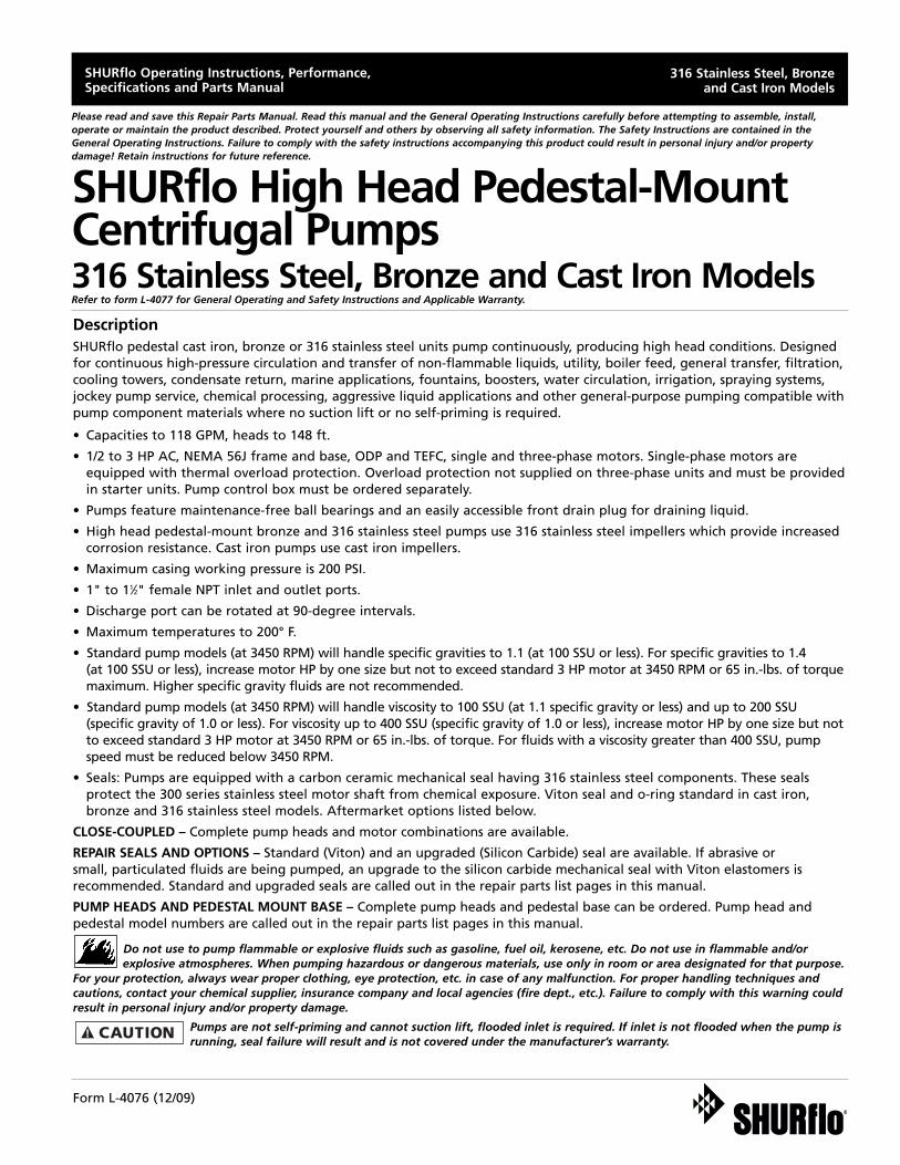
Model Ordering Codes and Options
M: Motor (with base)P: Pedestal
Example Model: CHPSV4 (will require 11⁄2 HP ODP motor with >1.15 Service Factor*)(motor not supplied with pedestal pump)
(1) (2) (3) (4) (5) (6) (7)CH P S V 4
CH: CentrifugalHigh HeadClosedImpeller
M: Motor(with Base)
P: Pedestal
S: 316 SS Bodyand Impeller
B: Bronze Body and 316 SS Impeller
C: Cast Iron Bodyand Impeller
B: Buna-N(Stainless Steel Case)
V: Viton(Stainless Steel Case)
C: Viton(Stainless Steel Case)(Silicon Carbide Sealand Seat Faces)
1 (1" - 11⁄4")
2 (1" - 11⁄4")
3 (1" - 11⁄4")
4 (11⁄2" - 11⁄4")
5 (11⁄2" - 11⁄4")
6 (11⁄2" - 11⁄4")
1: 1⁄3
2: 1⁄2
3: 3⁄4
4: 1
5: 11⁄2
6: 2
7: 3
X: 56JFrameMotor”wet-end kit”
Example:CHMSV1X
Blank: no code single phaseODP motor
3: 3 phase ODPmotor
T: 1 phase TEFC
3T: 3 phase TEFC
1st 2nd 3rd 4th 5th 6th 7th
Series Mounting MaterialSeal** Impeller Sz. Motor-Mounted Only(Mech) (NPT Ports) HP AC Type
NOTE: Not all order code combinations (configurations) are standardmodels available from the manufacturer. Custom model configurationsmay require ordering standard components and/or optional parts thatwill need to be assembled by the customer.
Manufacturer reserves the right to change model order codes, standardmodels, specifications, and performance without notification.
(*) ODP motors have > 1.15 service factors. Due to service factor, it is recommended TEFC motors are oversized by one HP increment.Pedestal Pumps are not supplied with a motor.
(**) Unless otherwise noted, seal faces are carbon on ceramic.
To identify
your impeller
size, see chart
in owner’s
manual.
3
SHURflo Operating Instructions, Performance, Specifications and Parts Manual
316 Stainless Steel, Bronze and Cast Iron Models
Form L-4076 (12/09)
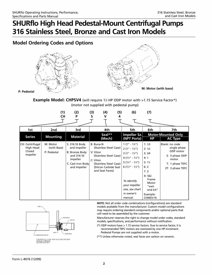
Performance at 3450 RPM – Standard Models (Water at 70°)
Impeller 316 Stainless Bronze Cast Iron HP** GPM of Water at Total Head in Feet* Max.Size Steel Models Models Models Required 10 20 30 40 50 70 90 110 130 Head
3 CHPSV3 CHPBV3 CHPCV3 1.5 58 56 52 48 44 34 23 3 – 112 6 CHPSV6 CHPBV6 CHPCV6 3 118 114 109 104 98 84 69 50 26 148
Impeller 316 Stainless Bronze Cast Iron HP** GPM of Water at Total Head in Feet* Max.Size Steel Models Models Models Required 6.9 13.9 20.8 27.8 34.7 48.6 62.5 76.3 90.2 Head
Performance at 2850 RPM – Standard Models (Water at 70°)
3 CHPSV3 CHPBV3 CHPCV3 1 48.3 46.6 43.3 40.0 36.7 28.3 19.2 2.5 – 77.76 CHPSV6 CHPBV6 CHPCV6 2 98.3 95.0 90.8 86.6 81.6 70.0 57.5 41.7 21.7 85.0
Impeller 316 Stainless Bronze Cast Iron HP** GPM of Water at Total Head in Feet* Max.Size Steel Models Models Models Required 2.5 5.0 7.5 10.0 12.5 17.5 22.5 27.5 32.5 Head
Performance at 1725 RPM – Standard Models (Water at 70°)
3 CHPSV3 CHPBV3 CHPCV3 1/2 29.0 28.0 26.0 24.0 22.0 17.0 11.5 1.5 – 28.06 CHPSV6 CHPBV6 CHPCV6 1/3 59.0 57.0 54.5 52.0 49.0 42.0 34.5 25.0 13.0 37.0
(*) Test data taken with water at 70°F (to convert data to PSI, divide feet of head by 2.31).Pump performance when pump is new. As pump wears, the performance will decrease.(**) AC HP required at specified RPM is HP rated to handle up to 100 SSU at full flow, with a maximum specific gravity of 1.1, or up to 200 SSU at 1.0 specific gravity or less.
NOTES: Max. Viscosity = For viscosity up to 400 SSU (at 1.0 specific gravity or less), increase motor HP by one size but not to exceed standard3 HP motor at 3450 RPM or 65 in.-lbs. of torque. For fluids with a viscosity greater than 400 SSU, pump speed must be reduced below 3450 RPM.Max. Casing PSI = 200 Max. RPM = 3450Max. Specific Gravity = up to 1.1 for standard models (at 100 SSU or less); HP must be increased by one size for specific gravities up to 1.4.Driver data is subject to change without notice; see label on driver for actual specifications.Manufacturer reserves the right to change performance without notification.
Specifications – Standard Models
DRIVE PUMP CONSTRUCTION (Wet End)Shaft Pedestal Shaft Port Size Motor Ship Wt.
Model Dia. Base Material FNPT Housing Impeller Adapter Seals* (lbs.)
316 Stainless Steel ModelsCHPSV3 5/8" CI 316 SS 11⁄4" x 1" 316 SS 316 SS 316 SS Viton 16CHPSV6 5/8" CI 316 SS 11⁄2" x 11⁄4" 316 SS 316 SS 316 SS Viton 19Bronze ModelsCHPBV3 5/8" CI 316 SS 11⁄4" x 1" BR 316 SS BR Viton 17CHPBV6 5/8" CI 316 SS 11⁄2" x 11⁄4" BR 316 SS BR Viton 20Cast Iron ModelsCHPCV3 5/8" CI 316 SS 11⁄4" x 1" CI CI CI Viton 16CHPCV6 5/8" CI 316 SS 11⁄2" x 11⁄4" CI CI CI Viton 19SS = Stainless Steel BR = Bronze CI = Cast Iron(*) Shaft Seal also contains 316SS stainless steel, ceramic, and carbon components.
NOTES: Standard model codes, less motor, are shown as examples. Manufacturer reserves the right to change specifications without notification.
4
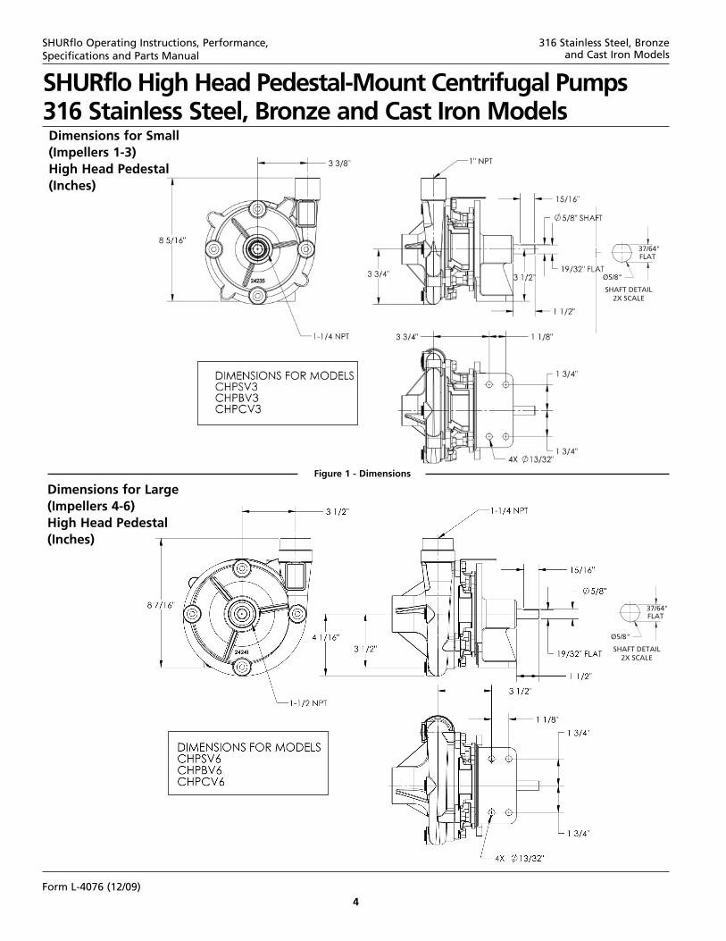
Dimensions for Small(Impellers 1-3)High Head Pedestal(Inches)
Dimensions for Large(Impellers 4-6)High Head Pedestal(Inches)
Figure 1 - Dimensions
SHURflo High Head Pedestal-Mount Centrifugal Pumps316 Stainless Steel, Bronze and Cast Iron Models
SHURflo Operating Instructions, Performance, Specifications and Parts Manual
316 Stainless Steel, Bronze and Cast Iron Models
Form L-4076 (12/09)
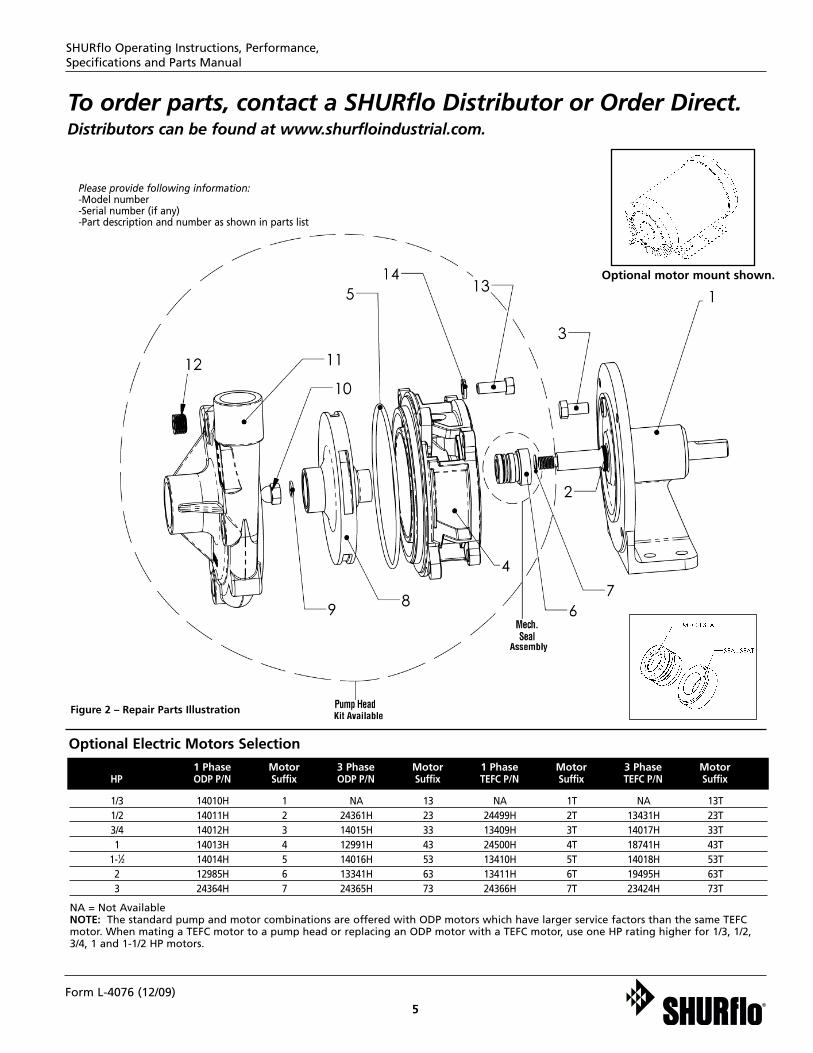
Please provide following information:-Model number-Serial number (if any)-Part description and number as shown in parts list
To order parts, contact a SHURflo Distributor or Order Direct.Distributors can be found at www.shurfloindustrial.com.
NA = Not AvailableNOTE: The standard pump and motor combinations are offered with ODP motors which have larger service factors than the same TEFCmotor. When mating a TEFC motor to a pump head or replacing an ODP motor with a TEFC motor, use one HP rating higher for 1/3, 1/2,3/4, 1 and 1-1/2 HP motors.
1/3 14010H 1 NA 13 NA 1T NA 13T1/2 14011H 2 24361H 23 24499H 2T 13431H 23T3/4 14012H 3 14015H 33 13409H 3T 14017H 33T1 14013H 4 12991H 43 24500H 4T 18741H 43T
1-1⁄2 14014H 5 14016H 53 13410H 5T 14018H 53T2 12985H 6 13341H 63 13411H 6T 19495H 63T3 24364H 7 24365H 73 24366H 7T 23424H 73T
1 Phase Motor 3 Phase Motor 1 Phase Motor 3 Phase MotorHP ODP P/N Suffix ODP P/N Suffix TEFC P/N Suffix TEFC P/N Suffix
Optional Electric Motors Selection
5
SHURflo Operating Instructions, Performance, Specifications and Parts Manual
Figure 2 – Repair Parts Illustration
Optional motor mount shown.
Form L-4076 (12/09)
6
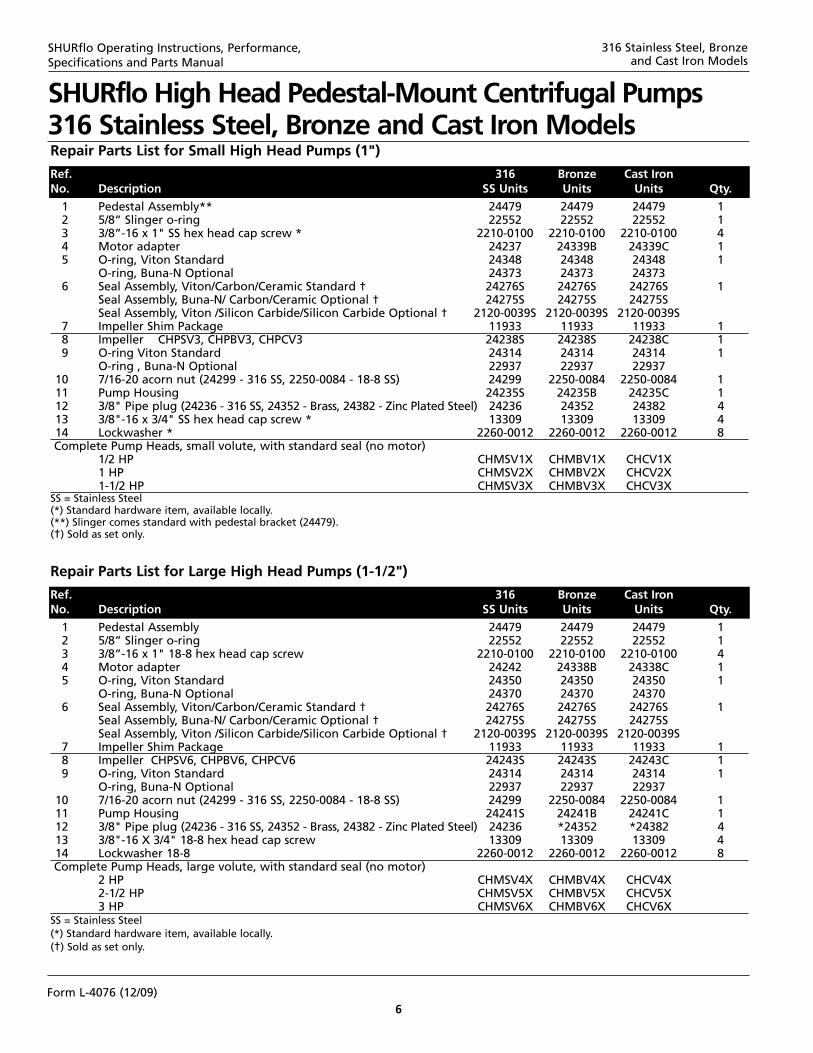
Repair Parts List for Small High Head Pumps (1")
Ref. 316 Bronze Cast IronNo. Description SS Units Units Units Qty.
Repair Parts List for Large High Head Pumps (1-1/2")
Ref. 316 Bronze Cast IronNo. Description SS Units Units Units Qty.
1 Pedestal Assembly 24479 24479 24479 12 5/8” Slinger o-ring 22552 22552 22552 13 3/8”-16 x 1" 18-8 hex head cap screw 2210-0100 2210-0100 2210-0100 44 Motor adapter 24242 24338B 24338C 15 O-ring, Viton Standard 24350 24350 24350 1
O-ring, Buna-N Optional 24370 24370 243706 Seal Assembly, Viton/Carbon/Ceramic Standard † 24276S 24276S 24276S 1
Seal Assembly, Buna-N/ Carbon/Ceramic Optional † 24275S 24275S 24275SSeal Assembly, Viton /Silicon Carbide/Silicon Carbide Optional † 2120-0039S 2120-0039S 2120-0039S
7 Impeller Shim Package 11933 11933 11933 18 Impeller CHPSV6, CHPBV6, CHPCV6 24243S 24243S 24243C 19 O-ring, Viton Standard 24314 24314 24314 1
O-ring, Buna-N Optional 22937 22937 2293710 7/16-20 acorn nut (24299 - 316 SS, 2250-0084 - 18-8 SS) 24299 2250-0084 2250-0084 111 Pump Housing 24241S 24241B 24241C 112 3/8" Pipe plug (24236 - 316 SS, 24352 - Brass, 24382 - Zinc Plated Steel) 24236 *24352 *24382 413 3/8"-16 X 3/4" 18-8 hex head cap screw 13309 13309 13309 414 Lockwasher 18-8 2260-0012 2260-0012 2260-0012 8Complete Pump Heads, large volute, with standard seal (no motor)
2 HP CHMSV4X CHMBV4X CHCV4X2-1/2 HP CHMSV5X CHMBV5X CHCV5X3 HP CHMSV6X CHMBV6X CHCV6X
SS = Stainless Steel(*) Standard hardware item, available locally.(†) Sold as set only.
SHURflo Operating Instructions, Performance, Specifications and Parts Manual
SHURflo High Head Pedestal-Mount Centrifugal Pumps316 Stainless Steel, Bronze and Cast Iron Models
1 Pedestal Assembly** 24479 24479 24479 12 5/8” Slinger o-ring 22552 22552 22552 13 3/8”-16 x 1" SS hex head cap screw * 2210-0100 2210-0100 2210-0100 44 Motor adapter 24237 24339B 24339C 15 O-ring, Viton Standard 24348 24348 24348 1
O-ring, Buna-N Optional 24373 24373 243736 Seal Assembly, Viton/Carbon/Ceramic Standard † 24276S 24276S 24276S 1
Seal Assembly, Buna-N/ Carbon/Ceramic Optional † 24275S 24275S 24275SSeal Assembly, Viton /Silicon Carbide/Silicon Carbide Optional † 2120-0039S 2120-0039S 2120-0039S
7 Impeller Shim Package 11933 11933 11933 18 Impeller CHPSV3, CHPBV3, CHPCV3 24238S 24238S 24238C 19 O-ring Viton Standard 24314 24314 24314 1
O-ring , Buna-N Optional 22937 22937 2293710 7/16-20 acorn nut (24299 - 316 SS, 2250-0084 - 18-8 SS) 24299 2250-0084 2250-0084 111 Pump Housing 24235S 24235B 24235C 112 3/8" Pipe plug (24236 - 316 SS, 24352 - Brass, 24382 - Zinc Plated Steel) 24236 24352 24382 413 3/8"-16 x 3/4" SS hex head cap screw * 13309 13309 13309 414 Lockwasher * 2260-0012 2260-0012 2260-0012 8Complete Pump Heads, small volute, with standard seal (no motor)
1/2 HP CHMSV1X CHMBV1X CHCV1X1 HP CHMSV2X CHMBV2X CHCV2X1-1/2 HP CHMSV3X CHMBV3X CHCV3X
SS = Stainless Steel(*) Standard hardware item, available locally.(**) Slinger comes standard with pedestal bracket (24479).(†) Sold as set only.
316 Stainless Steel, Bronze and Cast Iron Models
Form L-4076 (12/09)
FlexibleCoupling End
FlexibleCoupling End
FlexibleCoupling Center
Engine/MotorShaft
PumpShaft
77
SHURflo Operating Instructions, Performance, Specifications and Parts Manual
316 Stainless Steel, Bronze and Cast Iron Models
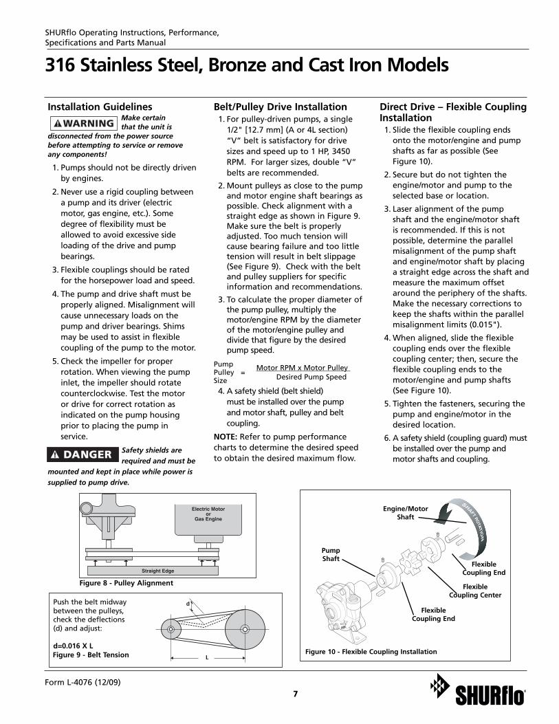
Figure 8 - Pulley Alignment
Push the belt midwaybetween the pulleys,check the deflections(d) and adjust:
d=0.016 X L
Installation GuidelinesMake certain that the unit is
disconnected from the power sourcebefore attempting to service or removeany components!
1. Pumps should not be directly drivenby engines.
2. Never use a rigid coupling betweena pump and its driver (electricmotor, gas engine, etc.). Somedegree of flexibility must beallowed to avoid excessive sideloading of the drive and pumpbearings.
3. Flexible couplings should be ratedfor the horsepower load and speed.
4. The pump and drive shaft must beproperly aligned. Misalignment willcause unnecessary loads on thepump and driver bearings. Shimsmay be used to assist in flexible coupling of the pump to the motor.
5. Check the impeller for proper rotation. When viewing the pumpinlet, the impeller should rotatecounterclockwise. Test the motor or drive for correct rotation as indicated on the pump housingprior to placing the pump inservice.
Safety shields arerequired and must be
mounted and kept in place while power issupplied to pump drive.
Belt/Pulley Drive Installation1. For pulley-driven pumps, a single
1/2" [12.7 mm] (A or 4L section)“V” belt is satisfactory for drivesizes and speed up to 1 HP, 3450RPM. For larger sizes, double “V”belts are recommended.
2. Mount pulleys as close to the pumpand motor engine shaft bearings aspossible. Check alignment with astraight edge as shown in Figure 9.Make sure the belt is properlyadjusted. Too much tension willcause bearing failure and too littletension will result in belt slippage(See Figure 9). Check with the beltand pulley suppliers for specificinformation and recommendations.
3. To calculate the proper diameter ofthe pump pulley, multiply themotor/engine RPM by the diameterof the motor/engine pulley anddivide that figure by the desiredpump speed.
Pump Pulley =
Motor RPM x Motor Pulley
Size Desired Pump Speed
4. A safety shield (belt shield) must be installed over the pumpand motor shaft, pulley and beltcoupling.
NOTE: Refer to pump performancecharts to determine the desired speedto obtain the desired maximum flow.
Direct Drive – Flexible CouplingInstallation1. Slide the flexible coupling ends
onto the motor/engine and pumpshafts as far as possible (See Figure 10).
2. Secure but do not tighten theengine/motor and pump to theselected base or location.
3. Laser alignment of the pump shaft and the engine/motor shaft is recommended. If this is not possible, determine the parallelmisalignment of the pump shaftand engine/motor shaft by placinga straight edge across the shaft andmeasure the maximum offsetaround the periphery of the shafts.Make the necessary corrections tokeep the shafts within the parallelmisalignment limits (0.015").
4. When aligned, slide the flexiblecoupling ends over the flexible coupling center; then, secure theflexible coupling ends to themotor/engine and pump shafts (See Figure 10).
5. Tighten the fasteners, securing thepump and engine/motor in thedesired location.
6. A safety shield (coupling guard) mustbe installed over the pump andmotor shafts and coupling.
Figure 9 - Belt Tension Figure 10 - Flexible Coupling Installation
Form L-4076 (12/09)
88
MaintenanceMake certain that the unit is
disconnected from the power sourcebefore attempting to service or removeany components!
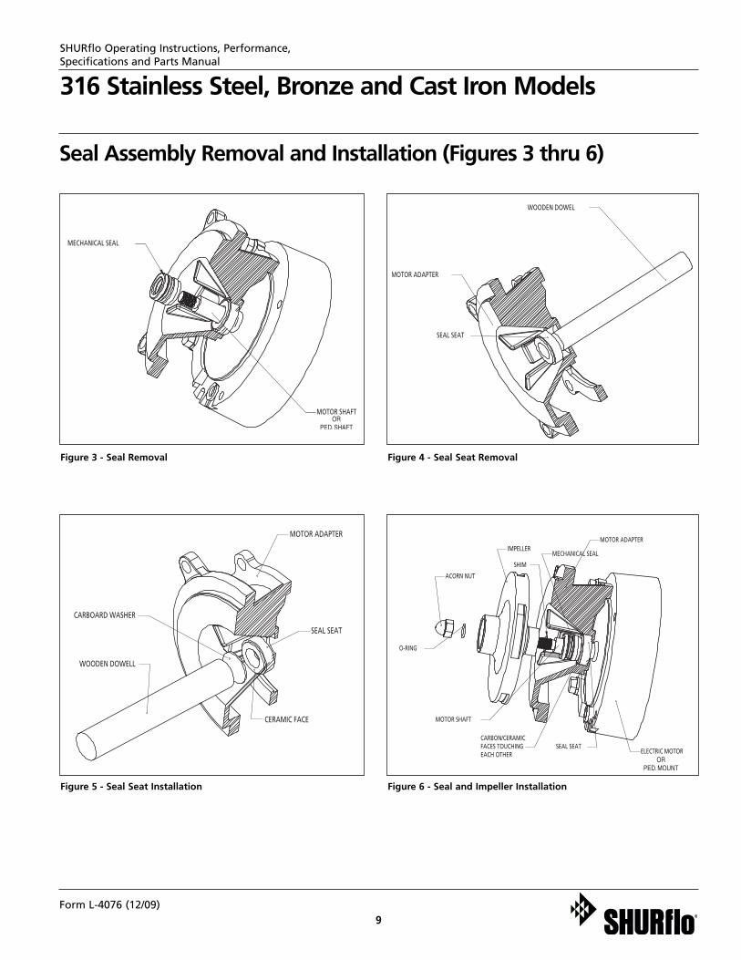
REMOVAL OF OLD SEAL ASSEMBLYShould the mechanical seal (Ref. No. 6)require repair, proceed as follows andrefer to Figures No. 2, 3, 4, 5 & 6.
IMPORTANT: Always replace both theseal seat and seal as an assembly toensure proper mating of components!Also, the impeller O-ring (Ref. No. 9)should be replaced anytime theimpeller lock nut (Ref. No. 10) hasbeen removed.
1. Remove bolts (Ref. No. 3)connecting the housing (Ref. No.11) to the adapter (Ref. No. 4).
2. Remove the housing.Care should be takennot to pinch or
”shave” the O-ring gasket (Ref. No. 5)between the adapter and the housing.
3. Use a box and/or socket wrench toremove the impeller nut (Ref. No.10). Remove the impeller O-ring(Ref. No. 9) and the impeller (Ref.No. 8).
NOTE: Pedestal shaft must be held inplace to remove impeller. Back of themotor either has slot in shaft (uselarge screwdriver to hold) or has 2flats on motor shaft (use 7/16" openend wrench to hold). Impeller (Ref.No. 8) and lock nut (Ref. No. 10)unscrew CCW when looking at thefront of the pump.
IMPORTANT: Care should be taken toensure that the same number andthickness of shim washers (Ref. No. 7)are replaced behind the impeller as wasremoved. The shim washers are locateddirectly behind the impeller and becomeloose as the impeller is removed.
4. The seal (part of Ref. No. 6) cannow be pulled from the shaft. (See figure 3).
5. Remove the motor adapter (Ref.No. 4) from the pedestal assemblyby removing the adapter bolts (Ref.No. 13).
6. Use a wooden dowel to push outthe seal seat (part of Ref. No. 6)from the adapter (Ref. No. 4) (Seefigure 4).
INSTALLATION OF NEW SEALASSEMBLY
The precisioncarbon/ceramic faces
on the mechanical seal are easilydamaged. Handle your repair sealcarefully. Do not touch the carbon/ceramicseal faces.
IMPORTANT: Be sure that shaftshoulder does not damage carbon face.
1. Thoroughly clean all surfaces of the seal seat cavity in adapter (Ref. No. 4).
2. Using a clean cloth, wipe the shaftand shaft sleeve and make certainthat they are perfectly clean.
NOTE: Inspect the motor shaft forscratches or spiral grooves. If theyexist, replace motor.
3. Wet the rubber portion of the newseal seat (part of Ref. No. 6) with alight coating of soapy water. Whilewearing clean gloves or using aclean light rag, press seal seatsquarely into adapter recess. Usethe cardboard washer (usuallysupplied with new seal) to placeover the polished ceramic surfaceand use a piece of pipe or dowelrod to press in firmly but gently(See figure 5). Avoid scratching theceramic face, usually white.
4. Dispose of cardboard washer.Check again to see that ceramicsurface is free of dirt and all otherforeign particles and that it has notbeen scratched or damaged.
5. Install the motor adapter (Ref. No.4) to the pedestal assembly usingbolts (Ref. No. 13). Be careful notto damage the seal seat when
sliding over the motor shaft.
6. Wet the inside rubber portion ofthe new seal (part of Ref. No. 6)with a light coating of soapy water.Slide onto the motor shaft with theprecision sealing surface (carbon)facing the seal seat ceramic face(See figure 6). This completes sealinstallation.
NOTE: A short “run-in” period may benecessary to provide completelyleakproof seal operation.
7. Screw impeller (Ref. No. 8) ontoshaft. Use screwdriver slot at rearof motor shaft (opposite thethreaded end) to securely tightenimpeller. A drop of removablethread lock should be applied to theimpeller threads. Impeller should betorqued to 15 to 18 ft-lbs. (180 to210 in-lbs.) (See figure 6).
NOTE: It may be necessary to removeplug in motor end cap to expose slot.If removed, be sure to reinstall plugAFTER pump is completely assembled.
8. Check if shaft turns freely byspinning impeller. If rubbing orbinding is found, remove impellerand add a shim (Ref. No. 7) toshaft, then recheck. Repeatprocedure until all rubbing iseliminated.
9. Slide O-ring (Ref. No. 9) ontoexposed shaft. Screw acorn nut(Ref. No. 10) onto shaft andtighten to 200 to 225 in-lbs.
10. Place O-ring (Ref. No. 5) on adaptermounting flange. Attach housingusing bolts (Ref. No. 3), beingcareful not to pinch or “shave” O-ring. As the housing is beingtightened, periodically spinimpeller to check for interferencewith housing.
Seal assembly willproduce minor drag
when spinning motor shaft, but rubbinganywhere else must be eliminated!Otherwise, damage to pump and/or motormay occur.
SHURflo Operating Instructions, Performance, Specifications and Parts Manual
316 Stainless Steel, Bronze and Cast Iron Models
SHURflo High Head Pedestal-Mount Centrifugal Pumps316 Stainless Steel, Bronze and Cast Iron Models
Form L-4076 (12/09)
9
316 Stainless Steel, Bronze and Cast Iron Models
SHURflo Operating Instructions, Performance, Specifications and Parts Manual
Figure 3 - Seal Removal Figure 4 - Seal Seat Removal
Figure 6 - Seal and Impeller InstallationFigure 5 - Seal Seat Installation
Seal Assembly Removal and Installation (Figures 3 thru 6)
Form L-4076 (12/09)
10
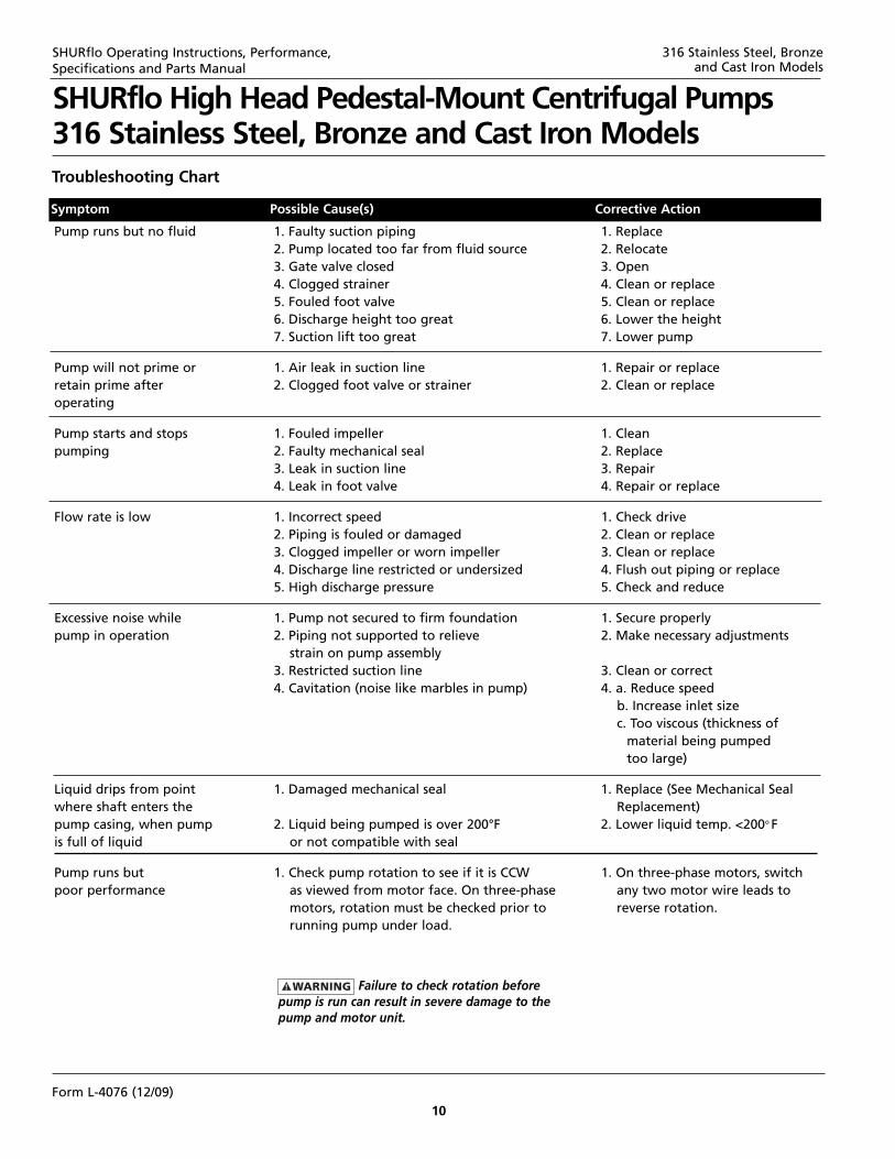
Pump runs but no fluid 1. Faulty suction piping 1. Replace2. Pump located too far from fluid source 2. Relocate3. Gate valve closed 3. Open4. Clogged strainer 4. Clean or replace5. Fouled foot valve 5. Clean or replace6. Discharge height too great 6. Lower the height7. Suction lift too great 7. Lower pump
Pump will not prime or 1. Air leak in suction line 1. Repair or replaceretain prime after 2. Clogged foot valve or strainer 2. Clean or replaceoperating
Pump starts and stops 1. Fouled impeller 1. Cleanpumping 2. Faulty mechanical seal 2. Replace
3. Leak in suction line 3. Repair4. Leak in foot valve 4. Repair or replace
Flow rate is low 1. Incorrect speed 1. Check drive2. Piping is fouled or damaged 2. Clean or replace3. Clogged impeller or worn impeller 3. Clean or replace4. Discharge line restricted or undersized 4. Flush out piping or replace5. High discharge pressure 5. Check and reduce
Excessive noise while 1. Pump not secured to firm foundation 1. Secure properlypump in operation 2. Piping not supported to relieve 2. Make necessary adjustments
strain on pump assembly3. Restricted suction line 3. Clean or correct4. Cavitation (noise like marbles in pump) 4. a. Reduce speed
b. Increase inlet sizec. Too viscous (thickness of
material being pumpedtoo large)
Liquid drips from point 1. Damaged mechanical seal 1. Replace (See Mechanical Seal where shaft enters the Replacement)pump casing, when pump 2. Liquid being pumped is over 200°F 2. Lower liquid temp. <200o Fis full of liquid or not compatible with seal
Pump runs but 1. Check pump rotation to see if it is CCW 1. On three-phase motors, switchpoor performance as viewed from motor face. On three-phase any two motor wire leads to
motors, rotation must be checked prior to reverse rotation. running pump under load.
Troubleshooting Chart
Symptom Possible Cause(s) Corrective Action
SHURflo Operating Instructions, Performance, Specifications and Parts Manual
Failure to check rotation beforepump is run can result in severe damage to thepump and motor unit.
316 Stainless Steel, Bronze and Cast Iron Models
SHURflo High Head Pedestal-Mount Centrifugal Pumps316 Stainless Steel, Bronze and Cast Iron Models
Form L-4076 (12/09)
11Form L-4076 (12/09)
Notes
SHURflo Operating Instructions, Performance, Specifications and Parts Manual
FLOW TECHNOLOGIES GROUP5900 Katella Ave. • Cypress, CA 90630Phone: (800) 854-3218 • (562) 795-5200 • Fax: (562) 795-7554
w
www.shurfloindustrial.com
SHURflo Operating Instructions, Performance, Specifications and Parts Manual
316 Stainless Steel, Bronze and Cast Iron Models
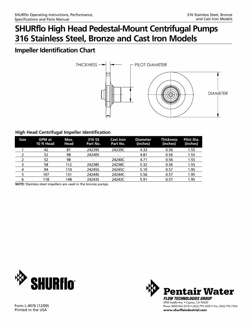
High Head Centrifugal Impeller Identification
Size GPM at Max. 316 SS Cast Iron Diameter Thickness Pilot Dia.10 ft Head Head Part No. Part No. (inches) (inches) (inches)
1 42 81 24239S 24239C 4.33 0.56 1.552 52 98 24240S - 4.81 0.56 1.552 52 98 - 24240C 4.71 0.56 1.553 58 112 24238S 24238C 5.32 0.56 1.554 94 110 24245S 24245C 5.10 0.57 1.955 107 131 24244S 24244C 5.56 0.57 1.956 118 148 24243S 24243C 5.91 0.57 1.95
NOTE: Stainless steel impellers are used in the bronze pumps.
Impeller Identification Chart
SHURflo High Head Pedestal-Mount Centrifugal Pumps316 Stainless Steel, Bronze and Cast Iron Models
Form L-4076 (12/09)Printed in the USA