SHURFLO 316 STAINLESS STEEL CLOSE-COUPLED...
12
SHURFLO ® 316 STAINLESS STEEL CLOSE-COUPLED SELF-PRIMING FLEXIBLE IMPELLER PUMPS OPERATION INSTRUCTIONS, PERFORMANCE, SPECIFICATIONS & PARTS MANUAL MODELS MRS9000, MRS9001, MRS9900, MRS9901, MRS15000, MRS15001 Form L-4093 (02/16) 1 DESCRIPTION SHURFLO ® 316 stainless steel, self- priming, positive-displacement, flex- ible impeller pumps provide a nearly pulseless flow with no metal-to-metal contact. Features 316 stainless steel pump body (impregnated with Teflon ® ), cover and wear plates, stainless steel shaft, Viton ® mechanical-type seal and o-rings with Nitrile impellers. Models have built-in cam profile for extended impeller life, concave manifold protects the impeller from intermittent dry run damage and increased startup suction lift. Mounted directly to NEMA frame AC Totally-Enclosed Fan-Cooled (TEFC) motors using an easy-installation pack- age, or as pump heads only for custom installations. Single-phase motors are thermally-overload protected. USES: Handle a wide range of indus- trial, marine, agricultural and commer- cial applications where non-abrasive fluids compatible with pump wet-end construction component materials are pumped. Pumps are suitable for the transfer of non-lubricating fluids, mild abrasives, fluids containing small parti- cles in suspension, and a wide variety of viscous fluids such as petroleum-based oils, silicone greases, and hydraulic fluids. The portable transfer units are ideal for water drainage transfer, barrel emptying, machine coolant recycling, and an assortment of related utility activities. NOTE: Flexible impeller failure will occur immediately if pump is run dry, and this is not covered under warranty. Use caution to not touch the pump if you have dry run it, because it will be extremely hot. ❚ Pumps are supplied with 56C face motors and totally-enclosed fan-cooled (TEFC) construction. ❚ Capacities up to 22.8 GPM at 1725 RPM. ❚ Maximum discharge pressure is 25 PSI (60 ft. of head). ❚ Max. RPM: 3450 (1725 with supplied motors). ❚ Suction lift to 12 ft. WARNING Do not use to pump flammable or explosive fluids such as gasoline, fuel oil, kerosene, etc. Do not use in flammable and/or explosive atmospheres. When pumping hazardous or dangerous materials, use only in a room or area designated for that purpose. For your protection, always wear proper clothing, eye protection, etc. in case of any malfunction. For proper han- dling techniques and cautions, contact your chemical supplier, insurance company and local agencies (fire dept., etc.). Failure to comply with this warning could result in personal injury and/or property damage. Please read and save this Repair Parts Manual. Read this manual and the General Operating Instructions carefully before at- tempting to assemble, install, operate or maintain the product described. Protect yourself and others by observing all safety in- formation. The Safety Instructions are contained in the General Operating Instructions. Failure to comply with the safety instruc- tions accompanying this product could result in personal injury and/or property damage! Retain instructions for future reference. ❚ Features 316 stainless steel pump body (impregnated with Teflon ® ), cover and wear plates, stainless steel shaft, Viton ® mechanical-type seal and o-rings with Nitrile impellers. Models have built-in cam profile for extended impel- ler life, concave manifold protects the impeller from intermittent dry run dam- age and increased startup suction lift. ❚ Maximum viscosity for pumps with standard electric motors up to 500 SSU and 25 PSI (60 ft. of head) at 1725 RPM or run at reduced speeds to handle a wide range of pump fluid viscosities (up to 2500 SSU) and specific gravity (up to 1.3). DO NOT pump oils or petroleum derivatives with optional neoprene impellers. (Maximum torque loads are found in the performance chart.) ❚ Pumps can operate bi-directionally (reversible). ❚ Temperature range with Nitrile impel- lers is 0°F - 180°F (optional neoprene impeller is 15°F - 130°F). ❚ NPT ports (3/4" to 11⁄4"). (Continued on Page 2)
Transcript of SHURFLO 316 STAINLESS STEEL CLOSE-COUPLED...

SHURFLO® 316 STAINLESS STEEL CLOSE-COUPLED SELF-PRIMING FLEXIBLE IMPELLER PUMPSOPERATION INSTRUCTIONS, PERFORMANCE, SPECIFICATIONS & PARTS MANUAL
MODELS MRS9000, MRS9001, MRS9900, MRS9901, MRS15000, MRS15001
Form L-4093 (02/16) 1
DESCRIPTION
SHURFLO® 316 stainless steel, self-priming, positive-displacement, flex-ible impeller pumps provide a nearly pulseless flow with no metal-to-metal contact. Features 316 stainless steel pump body (impregnated with Teflon®), cover and wear plates, stainless steel shaft, Viton® mechanical-type seal and o-rings with Nitrile impellers. Models have built-in cam profile for extended impeller life, concave manifold protects the impeller from intermittent dry run damage and increased startup suction lift. Mounted directly to NEMA frame AC Totally-Enclosed Fan-Cooled (TEFC) motors using an easy-installation pack-age, or as pump heads only for custom installations. Single-phase motors are thermally-overload protected.
USES: Handle a wide range of indus-trial, marine, agricultural and commer-cial applications where non-abrasive fluids compatible with pump wet-end construction component materials are pumped. Pumps are suitable for the transfer of non-lubricating fluids, mild abrasives, fluids containing small parti-
cles in suspension, and a wide variety of viscous fluids such as petroleum-based oils, silicone greases, and hydraulic fluids. The portable transfer units are ideal for water drainage transfer, barrel emptying, machine coolant recycling, and an assortment of related utility activities.
NOTE: Flexible impeller failure will occur immediately if pump is run dry, and this is not covered under warranty. Use caution to not touch the pump if you have dry run it, because it will be extremely hot.
❚ Pumps are supplied with 56C face motors and totally-enclosed fan-cooled (TEFC) construction.
❚ Capacities up to 22.8 GPM at 1725 RPM.
❚ Maximum discharge pressure is 25 PSI (60 ft. of head).
❚ Max. RPM: 3450 (1725 with supplied motors).
❚ Suction lift to 12 ft.
WARNING
Do not use to pump flammable or explosive fluids such as gasoline, fuel oil, kerosene, etc. Do not use in flammable and/or explosive atmospheres. When pumping hazardous or dangerous materials, use only in a room or area designated for that purpose. For your protection, always wear proper clothing, eye protection, etc. in case of any malfunction. For proper han-dling techniques and cautions, contact your chemical supplier, insurance company and local agencies (fire dept., etc.). Failure to comply with this warning could result in personal injury and/or property damage.
Please read and save this Repair Parts Manual. Read this manual and the General Operating Instructions carefully before at-tempting to assemble, install, operate or maintain the product described. Protect yourself and others by observing all safety in-formation. The Safety Instructions are contained in the General Operating Instructions. Failure to comply with the safety instruc-tions accompanying this product could result in personal injury and/or property damage! Retain instructions for future reference.
❚ Features 316 stainless steel pump body (impregnated with Teflon®), cover and wear plates, stainless steel shaft, Viton® mechanical-type seal and o-rings with Nitrile impellers. Models have built-in cam profile for extended impel-ler life, concave manifold protects the impeller from intermittent dry run dam-age and increased startup suction lift.
❚ Maximum viscosity for pumps with standard electric motors up to 500 SSU and 25 PSI (60 ft. of head) at 1725 RPM or run at reduced speeds to handle a wide range of pump fluid viscosities (up to 2500 SSU) and specific gravity (up to 1.3). DO NOT pump oils or petroleum derivatives with optional neoprene impellers. (Maximum torque loads are found in the performance chart.)
❚ Pumps can operate bi-directionally (reversible).
❚ Temperature range with Nitrile impel-lers is 0°F - 180°F (optional neoprene impeller is 15°F - 130°F).
❚ NPT ports (3/4" to 11⁄4").
(Continued on Page 2)

2
DESCRIPTION (Continued)
❚ Accessory NPT ports (1/8") for prim-ing, vacuum switch (pump protector) installation (to allow for dry run protec-tion) or pressure gauge installation.
316 STAINLESS STEEL MODELS Excellent for water-based fluids. Fea-tures 316 stainless steel pump body (impregnated with Teflon®), cover and wear plates, stainless steel shaft, Viton® mechanical-type seal and o-rings with
MODEL ORDERING CODES & OPTIONS
Nitrile impellers. Wet-end parts are constructed from 316 stainless steel, Teflon®, Viton®, carbon, ceramic and Nitrile.
REPAIR IMPELLERS AND OPTIONS Standard impellers are Nitrile, and they and the optional neoprene impeller can be located in the repair parts list pages in this manual.
Optional Close-Coupled Gear Speed
Reducers are available that mount directly between pump and motor to reduce pump speed for high viscosity or high specific gravity applications (See Appendix 2).
NOTE: Bronze flexible impeller pumps are also available as pedestal models or close-coupled for custom installation. Pedestal models are not equipped with motors.
NOTE
Not all order code combinations (configurations) are standard models available from the manufacturer. Custom model configu-rations may require ordering standard components and/or optional parts that will need to be assembled by the customer.Manufacturer reserves the right to change model order codes, standard models, specifications, and performance without notifi-cation. Standard motor speed is 1725 RPM. Maximum motor speed is 3450 RPM.(*) Standard motors are single phase, 1725 RPM, totally-enclosed fan-cooled.
Example Model: MRS9901
(1) M (2) R (3) S (4) 9 9 (5) 0 (6) 1
1st 2nd 3rd 4th 5th 6th
MOUNTING TYPE MATERIAL IMPELLER SIZE (PORTS)
IMPELLER MATERIAL
AC MOTOROPTIONS*
M: MotorMount
R: Flexible(Rubber) Impeller
S: 316Stainless
Steel
90 (3/4") - 3/4 HP99 (1") - 1 HP
150 (1-1⁄4") - 1-1⁄2 HP
0: Nitrile1: Neoprene
0: Pump only1: 1725 RPM2: 3450 RPM

3
PERFORMANCE (WITH WATER)
MODELS PORT SIZE* HP
MAX. IMPUT TORQUE IN. LBS. RPM
SUCTION LIFT** FREE FLOW 10 20 30 40 50 60†
Models With Motors
MRS9001 3/4 3/4 28 1725 8 7.4 7.1 6.7 6.2 5.5 4.8 3.8
MRS9901 1 1 37 1725 10 11.9 11.6 10.5 10.0 8.6 6.7 4.8
MRS15001 1-1/4 1-1/2 55 1725 12 22.8 21.2 20.9 20.0 19.0 17.1 14.3
Models Without Motors
MRS9000 3/4 3/4 28 1725 8 7.4 7.1 6.7 6.2 5.5 4.8 3.8
MRS9900 1 1 37 1725 10 11.9 11.6 10.5 10.0 8.6 6.7 4.8
MRS15000 1-1/4 1-1/2 55 1725 12 22.8 21.2 20.9 20.0 19.0 17.1 14.3
SPECIFICATIONS
MODELS Motor HpAC Motor
Type Nema Frame Motor Voltage Amps PH HZOverload
Protection** Motor RPMPump Shaft
Size Motor ShaftMotor
Adapter
Models With Motors
MRS9001 3/4 TEFC 56C 115/230 10.8/5.4 1 60 Yes 1725 5/8 Keyed 5/8 Keyed CI
MRS9901 1 TEFC 56C 115/230 12.8/6.4 1 60 Yes 1725 5/8 Keyed 5/8 Keyed CI
MRS15001 1-1/2 TEFC 56C 115/230 17.2/8.6 1 60 Yes 1725 5/8 Keyed 5/8 Keyed CI
Models Without Motors
MRS9000 — — — — — — — — — 5/8 Keyed — —
MRS9900 — — — — — — — — — 5/8 Keyed — —
MRS15000 — — — — — — — — — 5/8 Keyed — —
PUMP CONSTRUCTION (WET END)
MODELS Port Size (in.) Pump & Body Cam Flexible Impeller*** Wear Plates Shaft Seal & O-rings* Ship Wt. (lbs.)
Models With Motors
MRS9001 3/4 316 SS Nitrile 316 SS 316 SS Viton® 44
MRS9901 1 316 SS Nitrile 316 SS 316 SS Viton® 45
MRS15001 1-1/4 316 SS Nitrile 316 SS 316 SS Viton® 59
Models Without Motors
MRS9000 3/4 316 SS Nitrile 316 SS 316 SS Viton® 5
MRS9900 1 316 SS Nitrile 316 SS 316 SS Viton® 6
MRS15000 1-1/4 316 SS Nitrile 316 SS 316 SS Viton® 7
GPM Pumping Water at 70°F @ Total Feet of Head
Test data taken with water at 70° F (to convert data to PSI, divide feet of head by 2.31).Pump performance when pump is new. As pump wears, the performance will decrease.(†) Extended operation beyond 60 feet of head will result in immediate impeller failure.(*) Female NPT inlet and outlet (in inches).(**) Suction lift requires wetted impellers and seal chamber.
NOTES: Consult tables on HP adders and speed recommendations for high viscosity fluids. The pump relationship between volume (GPM), pressure (PSI), speed (RPM) and horsepower is shown on Performance Chart in SHURFLO® Motor Manual form L-4082. When pumping a more viscous liquid, a slower speed, a larger pipe size pump, and possibly a larger motor should be selected.
Max. Viscosity = 500 SSU at 1725 RPM with the motor supplied (at 1.0 specific gravity).Max. Input Torque = see chart above.Max. RPM = 3450Max. Specific Gravity = 1.0 at 25 PSI, up to 1.3 at lower PSI & viscosity.Do not use Neoprene impellers with oil.Manufacturer reserves the right to change performance without notification.
SS = Stainless Steel CI = Cast Iron TEFC = Totally-Enclosed Fan-Cooled(*) Viton® mechanical seals have 316 Stainless Steel series components and carbon and ceramic wear surfaces.(**) Manual or Automatic - Check motor supplied.(***) Impeller has a 316 Stainless Steel insert.
NOTES: Driver data is subject to change without notice; see label on driver for actual information.All dimensions in inches unless otherwise specified. To prevent dry run operation, a vacuum switch (pump protector) is recommended.Manufacturer reserves the right to change specifications without notification.
4
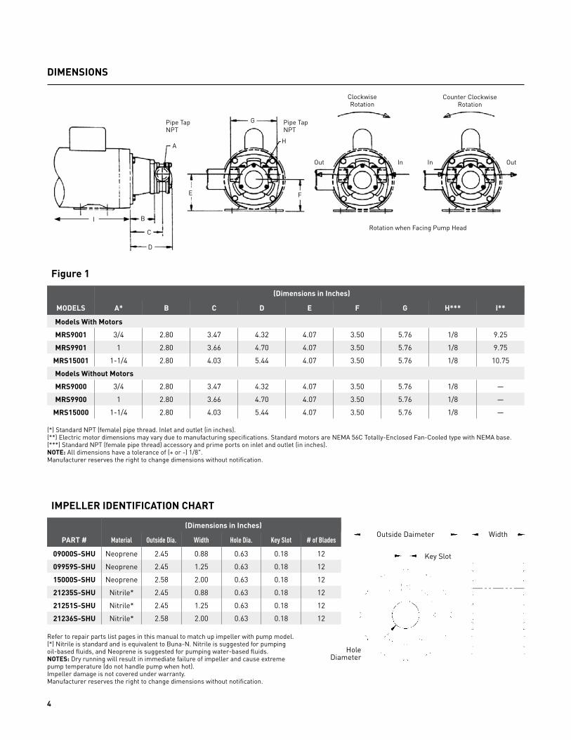
DIMENSIONS
Figure 1
(Dimensions in Inches)
MODELS A* B C D E F G H*** I**
Models With Motors
MRS9001 3/4 2.80 3.47 4.32 4.07 3.50 5.76 1/8 9.25
MRS9901 1 2.80 3.66 4.70 4.07 3.50 5.76 1/8 9.75
MRS15001 1-1/4 2.80 4.03 5.44 4.07 3.50 5.76 1/8 10.75
Models Without Motors
MRS9000 3/4 2.80 3.47 4.32 4.07 3.50 5.76 1/8 —
MRS9900 1 2.80 3.66 4.70 4.07 3.50 5.76 1/8 —
MRS15000 1-1/4 2.80 4.03 5.44 4.07 3.50 5.76 1/8 —
IMPELLER IDENTIFICATION CHART
(Dimensions in Inches)
PART # Material Outside Dia. Width Hole Dia. Key Slot # of Blades
09000S-SHU Neoprene 2.45 0.88 0.63 0.18 12
09959S-SHU Neoprene 2.45 1.25 0.63 0.18 12
15000S-SHU Neoprene 2.58 2.00 0.63 0.18 12
21235S-SHU Nitrile* 2.45 0.88 0.63 0.18 12
21251S-SHU Nitrile* 2.45 1.25 0.63 0.18 12
21236S-SHU Nitrile* 2.58 2.00 0.63 0.18 12
(*) Standard NPT (female) pipe thread. Inlet and outlet (in inches).(**) Electric motor dimensions may vary due to manufacturing specifications. Standard motors are NEMA 56C Totally-Enclosed Fan-Cooled type with NEMA base.(***) Standard NPT (female pipe thread) accessory and prime ports on inlet and outlet (in inches).NOTE: All dimensions have a tolerance of (+ or -) 1/8".Manufacturer reserves the right to change dimensions without notification.
Refer to repair parts list pages in this manual to match up impeller with pump model.(*) Nitrile is standard and is equivalent to Buna-N. Nitrile is suggested for pumpingoil-based fluids, and Neoprene is suggested for pumping water-based fluids.NOTES: Dry running will result in immediate failure of impeller and cause extremepump temperature (do not handle pump when hot).Impeller damage is not covered under warranty.Manufacturer reserves the right to change dimensions without notification.
Pipe TapNPT
Pipe TapNPT
ClockwiseRotation
Counter ClockwiseRotation
Rotation when Facing Pump HeadB
A
C
D
G
H
In In OutOut
E F
I
Outside Daimeter
Key Slot
Width
HoleDiameter

5
WARNING
Check motor. It may be equipped with an automatic resetting thermal protector and may restart unexpectedly (see specifica-tions chart). Protector tripping is an indication of motor overloading as a result of operating the pump at too high a pressure (over 25 PSI or 60 feet of head), too high of viscosity, too high of specific gravity, excessively high or low voltage, inadequate wiring, incorrect motor connections, too small a motor (sized incorrectly, not enough HP), or a defective motor or pump.Do not handle pump with wet hands or when standing in water. Failure to follow the General Safety Information and all warn-ings could result in fatal electrical shock!
INSTALLATION
IMPORTANT: In any installations where property damage and/or personal injury can occur when the pump is not operat-ing due to power outages, discharge line freezing, or any other reason, a back-up system(s) and/or warning system(s) should be used. In order to safely use this product, familiarize yourself with this pump and also with the liquid (chemical, etc.)that is going to be pumped through the unit. This pump is not suitable for many liquids.
1. Locate the pump as close to the liquid source as possible, making the suction line as short and direct as possible.
PIPING
SUCTION
2. Avoid excessive lengths or number of fittings and bends in the suction line.
3. Attach suction line to suction inlet (See Figure 1 for proper rotation).
NOTE: An optional vacuum switch (pump protector) is recommended to prevent pump dry run. It should be mounted on the suction side of the pump. Refer to installation/operation in-structions provided with vacuum switch (See Figure 2).
4. It is recommended that same size pipe as pump ports be used or, in cases requiring lengthy piping, the next larger size pipe be used.
5. If suction level is greater than what is indicated in the performance chart, attach a foot valve below liquid level at end of suction line to ensure posi-tive priming. Also note: If fluid specific gravity is greater than 1.0 or viscosity greater than 500 SSU, a foot valve is also recommended.
NOTE: If a foot valve (or check valve) is not used in the suction line, it may be necessary to refill the pump every time the unit is stopped and you wish to restart the pump. This depends on the length of time between starts and whether or not the impeller is wet enough to close cavities to affect a prime.
6. If solid contaminates are suspected in a liquid, place a filter in the suction line.
7. Be certain all suction piping connec-tions are airtight.
NOTE: Assure airtight pipe connections with the use of a pipe joint sealant.
DISCHARGE
8. Attach discharge piping to the dis-charge outlet.
WARNING Support pump and piping during as-sembly and after installation. Failure to do so may cause piping to break, pump to fail, motor bearing failures, etc., all of which can result in property damage and/or personal injury.
NOTE: Should the pump need to be self-draining, the pump head should be mounted in the vertical position with the suction port facing down. When pumping high viscosity fluids, the vertical position can be used with the suction port facing up and the pump mounted under the source. Increasing the suction pipe size and eliminating bends and elbows also assists in pumping high viscosity fluids. Max. viscosity is 500 SSU at 1725 RPM.
9. If a shut-off valve or handgun is re-quired in discharge line, provide a pres-sure relief valve for pump protection.
WARNING Shutting off discharge without provid-ing pressure relief can cause extreme overpressure which can result in pump and/or motor failure. Do not exceed 25 PSI (or 60 feet of head) pump or system pressure.
10. Operation under shut-off discharge conditions will overheat and damage pump and impeller.
NOTE: Globe valve or other restrictive valves should not be used as shut-off mechanism as they are restrictive in nature and will seriously affect pump performance.
11. After all piping and controls (not supplied with unit) have been installed, unit is ready for operation.
Figure 2 - Vacuum Switch Installation
Inlet orSuction Side

6
OPERATION
WARNING Do not run pump dry, as permanent damage to the pump impeller, seal, pump housing and wear plates will re-sult. Suction pressure should never be greater than the discharge pressure. Dry running will result in immediate failure of impeller and cause extreme pump temperature (do not handle pump when hot). Impeller damage is not covered under warranty.
1. All pumps must be primed before start-up and filled with fluid (See Figure 3). Never operate a pump unless it is se-cured to a solid foundation and all safety shields are installed.
Upon start-up, maintain a minimum of 15 PSI (1 BAR) operating pressure on the pump. This will allow any remaining air to be driven from the seal chamber and will ensure liquid circulation to the seal.
2. Flexible impeller pumps are built to very close tolerances and this tolerance must not be altered. The liquids must, there-fore, be free of all abrasives. Sand, silt, wettable powders, etc. must be avoided.
3. When pumping a more viscous (be-yond 500 SSU) liquid; a slower speed, a larger pipe size pump, and possibly a larger motor should be selected.
NOTE: See performance chart for Max. Torque.
4. Recheck motor and pump rotation. Pump rotation is by-directional (See Figure 1).
PRESSURE RELIEF VALVE
5. Standard models do not include a pressure relief valve. If discharge is go-ing to be shut off, an external pressure relief valve should be installed.
GEAR SPEED REDUCER OPTIONS
A gear reducer can be directly mounted between a standard pump and mo-tor combination. Gear speed reducers are available for applications with high specific gravity, or when viscosities are greater than 500 SSU, using a standard 1725 RPM motor (See Appendix 2). The pump relationship between volume (GPM), pressure (PSI), speed (RPM), viscosity, specific gravity and horse-power is shown on performance chart in SHURFLO® Motor Manual form L-4082.
6. Unit is ready for operation.
Figure 3 - Prime Plug
Remove either plug and fill with
fluid and reinstall plug.
MAINTENANCE
WARNING Make certain that the power source is disconnected before attempting to ser-vice or disassemble any components! If the power disconnect is out of sight, lock it in the open position and tag to prevent application of power.
CLEANING
Clean the suction line filter at regular intervals.
ELECTRIC MOTOR
Properly selected and installed, elec-tric motors are capable of operating for years with minimal maintenance. Periodically clean dirt accumulations from motors.
GENERAL
Check the pump to motor shaft coupler alignment at regular intervals.
Periodically check that electrical con-nections are tight. Pump should be drained if placed in an area that is subject to freezing temperatures and should not be operated until tempera-ture permits.
To store the pump, place a small quantity of light oil or some other stor-age preservative, compatible with your application, in the pump and rotate the shaft very slowly to work the oil throughout the gears and the body.
PUMP REPAIRIMPELLER DISASSEMBLYRefer to Figure 8.
NOTE: The impeller is a common wear item in this pump and frequent replace-ment is suggested. Impeller can become torn, distorted and overheated becom-ing brittle. When this happens, impel-ler blade fragments can come off the
impeller and be pumped downstream or block pump ports or plumbing. It is not recommended to flip around a used/worn impeller for reinstallation. (See Appendix 1 for illustrations of common impeller problems.)
1a. Remove the three screws (Ref. No. 2) which hold the cover plate (Ref. No. 1), wear plate (Ref. No. 10) and O-ring (Ref. No. 11) to pump body (Ref. No. 3).
1b. The impeller (Ref. No. 12) can be removed using two pair of pliers to grip two of the impeller’s vanes on opposite sides of the impeller (See Figure 4).
1c. Inspect drive key, cover and in-ternal wear plates, pump body inside and cam for wear. If parts are worn, replace, as worn parts will cause poor pump performance including poor suction lift, discharge pressure and

7
flow. If numerous components are worn, it’s suggested to replace the complete pump head. (See Pump and Seal Disassembly section for further pump disassembly instructions.)
IMPELLER ASSEMBLY
2a. Place some anti-seize compound on impeller shaft and key. Install the impeller (Ref. No. 12) over the drive shaft using a non-petroleum-based lubricant such as silicone or soapy water. The impeller is installed using a twisting motion in the same direc-tion as motor rotation. The key slot of the impeller needs to line up with key on the drive shaft (See Figure 5).
2b. Install o-ring (Ref. No. 11) into pump body housing groove, insert wear plate (Ref. No. 10) and put cover (Ref. No. 1) on pump body being sure not to pinch o-ring. Tighten the three screws (Ref. No. 2) to 36 in.-lbs.
NOTE: Wear plates (Ref. No. 10) can be flipped to create new wearing surfaces.
PUMP AND SEAL DISASSEMBLY
3a. Remove impeller (Ref. No. 11) and drive key (Ref. No. 13). (See Impeller Disassembly.)
NOTE: The cam is not removable. If cam is worn, pump body replacement is required.
3b. Remove the four bolts (Ref. No. 16) holding pump assembly to motor face. Pump assembly can now be readily removed from the motor.
3c. Remove three screws (Ref. No. 6) which retain pump body (Ref. No. 3), o-ring (Ref. No. 11), motor adapter (Ref. No. 15), wear plate (Ref. No. 10) and seal retainer plate (Ref. No. 5). These parts will separate upon disas-sembly except for the seal seat and retaining ring.
3d. Pry out seal retaining ring (Ref. No. 18), and press out seal seat (Ref. No. 8) from seal retaining plate (Ref. No. 5).
3e. Seal (Ref. No. 7) can now be removed from pump shaft (Ref. No. 4). There is a spacing washer behind the seal that spaces the seal properly against the drive shaft collar. This spacer is included with a new seal and does not have a separate part number.
3f. The pump drive shaft (Ref. No. 4), along with the drive shaft key (Ref. No. 14) and the shaft collar (Ref. No. 9), do not need to be removed from the motor unless worn, or motor needs replacement.
PUMP AND SEAL ASSEMBLY
4a. If the pump drive shaft (Ref. No. 4) with the drive shaft key (Ref. No. 14) and the shaft collar (Ref. No. 9) were removed from motor, then reinstall in reverse order. Place some anti-seize compound on motor shaft and drive shaft key (Ref. No. 14). Slide the pump drive shaft (Ref. No. 4) over the motor shaft, aligning the key with the key slot, and push as far onto the motor as possible. Slide shaft collar (Ref. No. 9) over the pump shaft as far back as it will go. Align the collar set screw over the key in the pump drive shaft slot and tighten collar set screw,
compressing the key to the motor shaft.
NOTE: Installing a new seal is always recommended when pump is disas-sembled to the point of seal removal. The precision carbon/ceramic faces on the mechanical seal are easily damaged. Handle your repair seal carefully. Do not touch the carbon/ceramic seal faces.
4b. Thoroughly clean all surfaces of the seal seat cavity in seal retaining plate (Ref. No. 5).
4c. Using a clean cloth, wipe the shaft and shaft sleeve and make certain that they are perfectly clean.
NOTE: Inspect the pump drive shaft for scratches or spiral grooves. If they exist, replace shaft.
4d. Wet the rubber portion of the new seal seat (part of Ref. No. 8) with a light coating of soapy water. While wearing clean gloves or using a clean light rag, press seal seat squarely into seal retaining plate recess (Ref. No. 5). Use the cardboard washer (usually supplied with new seal) to place over the polished ceramic surface and use a piece of pipe or dowel rod to press in firmly, but gently. Avoid scratching the ceramic face, usually white (See Figure 6).
4e. Dispose of cardboard washer. Check again to see that ceramic surface is free of dirt and all other foreign particles and that it has not been scratched or damaged.
4f. Install seal retaining ring (Ref. No 18) over seal seat (Ref. No 8) into seal retaining plate (Ref. No. 5).
(Continued on Page 8)
Figure 4 - Impeller Removal
Figure 5 - Impeller Installation Figure 6 - Seal Seat Installation
Insert seal seat into seal seat
retainer pushing in with cardboard or wood dowel. The
white ceramic face should be outward.

8
4g. Wet the inside rubber portion of the new seal (part of Ref. No. 7) with a light coating of soapy water. Slide seal spacer onto the pump drive shaft. Then slide the seal with the precision sealing surface (carbon) facing the front of the pump drive shaft, which will match up with the seal seat ce-ramic face installed in the seal retain-ing plate (Ref. No. 5) (See Figure 7).
MAINTENANCE (Continued)
4h. Reinstall three screws (Ref. No. 6) which retain pump body (Ref. No. 3), O-ring (Ref. No. 11), motor adapter (Ref. No. 15), wear plate (Ref. No. 10) and seal retainer plate (Ref. No. 5). Make sure the o-ring (Ref. No. 11) and wear plate (Ref. No. 10) slide into the groove of the pump body, not pinching the O-ring.
NOTE: Wear plates (Ref. No. 10) and the pump body (Ref. No. 3) can be flipped to create new wearing surfaces.
4i. Pump assembly can now be readily reinstalled to the motor. Be careful not to damage the seal seat when sliding over the pump drive shaft. Reinstall the four bolts (Ref. No. 16) holding pump assembly to motor face. This completes seal installation.
4j. Install impeller (See Impeller As-sembly).
NOTE: A short “run-in” period may be necessary to provide completely leak-proof seal operation.
4k. All pumps must be primed before start-up and filled with fluid (See Fig-ure 3). Never operate a pump unless it is secured to a solid foundation and all safety shields are installed.
WARNING Do not run pump dry, as permanent damage to the pump impellers, seal, pump housing and wear plates will re-sult. Suction pressure should never be greater than the discharge pressure. Dry running will result in immediate failure of impeller and cause extreme pump temperature (do not handle pump when hot). Impeller damage is not covered under warranty.
Figure 7 - Seal Installation
Push seal into pump drive shaft with carbon facing outward.
Seal Spacer
Collar
9
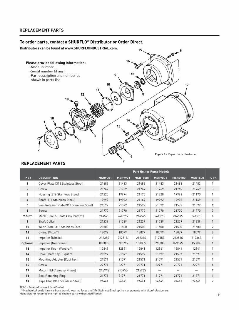
REPLACEMENT PARTS
REPLACEMENT PARTS
Part No. for Pump Models
KEY DESCRIPTION MSR9001 MSR9901 MSR15001 MSR9001 MSR9900 MSR1500 QTY.
1 Cover Plate (316 Stainless Steel) 21483 21483 21483 21483 21483 21483 1
2 Screw 21769 21769 21769 21769 21769 21769 3
3 Housing (316 Stainless Steel) 21220 19994 21170 21220 19994 21170 1
4 Shaft (316 Stainless Steel) 19992 19992 21169 19992 19992 21169 1
5 Seal Retainer Plate (316 Stainless Steel) 21572 21572 21572 21572 21572 21572 1
6 Screw 21770 21770 21770 21770 21770 21770 3
7 & 8* Mech. Seal & Shaft Assy. (Viton®) 24457S 24457S 24457S 24457S 24457S 24457S 1
9 Shaft Collar 21239 21239 21239 21239 21239 21239 1
10 Wear Plate (316 Stainless Steel) 21500 21500 21500 21500 21500 21500 2
11 O-ring (Viton®) 18079 18079 18079 18079 18079 18079 2
12 Impeller (Nitrile) 21235S 21251S 21236S 21235S 21251S 21236S 1
Optional Impeller (Neoprene) 09000S 09959S 15000S 09000S 09959S 15000S 1
13 Impeller Key - Woodruff 12841 12841 12841 12841 12841 12841 1
14 Drive Shaft Key - Square 21597 21597 21597 21597 21597 21597 1
15 Mounting Adapter (Cast Iron) 21571 21571 21571 21571 21571 21571 1
16 Screw 22771 22771 22771 22771 22771 22771 4
17 Motor (TEFC Single-Phase) 21594S 21595S 21596S — — — 1
18 Seal Retaining Ring 21771 21771 21771 21771 21771 21771 1
19 Pipe Plug (316 Stainless Steel) 24441 24441 24441 24441 24441 24441 2
To order parts, contact a SHURFLO® Distributor or Order Direct.Distributors can be found at www.SHURFLOINDUSTRIAL.com.
TEFC = Totally-Enclosed Fan-Cooled(*) Mechanical seals have carbon ceramic wearing faces and 316 Stainless Steel spring components with Viton® elastomers.Manufacturer reserves the right to change parts without notification.
Please provide following information:-Model number-Serial number (if any)-Part description and number as
shown in parts list
Figure 8 - Repair Parts Illustration

10
APPENDIX 1 - IMPELLER PUMP INSPECTION, COMMON PROBLEMS & OPERATION
OPERATION: HOW AN IMPELLER PUMP WORKS
THREE TIPS TO HELP YOU INSTALL YOUR NEW SHURFLO® IMPELLER
SHURFLO® recommends replacing your impeller annually. Proper storage of the impellers during a prolonged lay-up can help maintain the life of the impeller.
Remove the impeller from the housing and store it in a cool, dark place. This will avoid the following:
❚ Copper bonding of the impeller to the housing❚ Vanes “setting” into position as stored in the housing❚ Ultraviolet deterioration
❚ Use a non-petroleum-based lubricant (silicone or soapy water) to help slide the impeller into the housing.❚ Install the impeller with a twisting motion onto the shaft. Never force an impeller onto the shaft.❚ Impeller must be able to move freely on the shaft to properly prime and function.(Use a small amount of non-petroleum-based lubricant to help hold the O-ring or gasket when replacing the cover).
RECOMMENDED INSPECTION TO BE PERFORMED AT ANY SERVICE INTERVAL
Impeller: Inspect for cracks or tears. Also, inspect for excessive abrasion of vane ends. Replace annually or if any of the conditions exist (see picture).
Wear Rate: Inspect for wear, flatness, and pin for fatigue. Replace at minor and major pump rebuild or if wear is evident to maintain pump flow and suction performance.
Cam: Replace at major pump rebuild or if pitting/wear is evident.
Cover: Replace at major pump rebuild or if wear exists to maintain pump flow and suction performance.
Mechanical Seal: Replace at minor and major pump rebuild or if leaking.
Lip Seal: Replace at minor and major pump rebuild or if leaking.
Shaft: Inspect for wear in area of lip seal and rubber impeller. Grooving of lip seal area or heavy fretting of the impeller end shaft will require shaft replacement.
Bearing: Inspect for loss of grease, corrosion or rough rotation. Replace at major pump rebuild or if in doubt.
1. A self-priming vacuum is created as the flexible impeller vanes straighten upon leaving the cam, drawing liquid into the pump.
2. The rotating impeller carries liquid from the inlet to the outlet port. As a consequence of their design, flexible impeller pumps can pass fairly large solids.
3. When the flexible impeller vanes regain contact with the cam, they bend and the liquid is discharged from the pump in a uniform flow. Liquids can be pumped in the opposite direction by reversing the rotation of the pump.

11
GEAR SPEED REDUCER OPTIONS
APPENDIX 2 - OPTIONAL C-FLANGED PUMP SPEED GEAR REDUCERS
A gear reducer can be directly mounted between a standard pump and mo-tor combination. Gear speed reducers are available for applications with high specific gravity, or when viscosities are greater than 500 SSU, using a standard
1725 RPM motor. The pump relation-ship between volume (GPM), pressure (PSI), speed (RPM), viscosity, specific gravity and horsepower is shown on performance chart in SHURFLO® Motor Manual form L-4082.
MODEL DESCRIPTION L* M* RPM OUT** SHIP WT. (lbs.)
AGR56C600 Gear Reducer, 56C to 56C, 3.0 Ratio 5.177 1.675 583 21
AGR56C900 Gear Reducer, 56C to 56C, 2.0 Ratio 5.177 1.675 875 21
AGR56C1200 Gear Reducer, 56C to 56C, 1.5 Ratio 5.177 1.675 1167 21
(*) L dimension (in inches) is length of the gear reducer. M dimension (in inches) is the offset of the reducer output centerline from the motorcenterline. All reducers may be rotated in 90° increments changing the orientation of the offset from top to side to bottom.(**) Based on 1750 RPM motor speed.
Disassemble Pump From Motor and Insert Gear Reducer. Illustration depicts gear pump, but same principle applies to flexible impeller pumps.
Gear Reducer Installed between Pump and Motor (References L and M are dimensions in chart above.) Illustration depicts gear pump, but same principle applies to flexible impeller pumps.

12
3545 HARBOR GATEWAY SOUTH, SUITE 103, COSTA MESA, CA 92626, (800) 854-3218 WWW.SHURFLO.COM
All Pentair trademarks and logos are owned by Pentair, Inc. All other brand or product names are trademarks or registered marks of their respective owners.Because we are continuously improving our products and services, Pentair reserves the right to change specifications without prior notice.Pentair is an equal opportunity employer.
Form L-4093 Rev. A 02/16 ©Pentair, Inc. All Rights Reserved.