Show Control User's Guide - Alcorn...
276
Show Control User's Guide V16+, V2+ 16 Channel & 2 Channel Show Controllers IO64 Intelligent I/O Expander DMX Machine Scripted Lighting Controller SMPTE Machine SMPTE Reader and Generator
Transcript of Show Control User's Guide - Alcorn...

Show Control User's Guide V16+, V2+ 16 Channel & 2 Channel Show Controllers
IO64 Intelligent I/O Expander
DMX Machine Scripted Lighting Controller
SMPTE Machine SMPTE Reader and Generator

User's Guide To
Show Control
by Alcorn McBride Inc.

Document Revision 3.3
Document Number 110-100353.55
January 23, 2014
Copyright 1986-2014 Alcorn McBride, Inc. All rights reserved.
Every effort has been made to assure the accuracy of the information contained
in this manual, and the reliability of the hardware and software. Errors
sometimes can go undetected, however. If you find one, please bring it to our
attention so that we can correct it for others.
Alcorn McBride Inc. reserves the right to make changes to these products,
without notice, in order to improve their design or performance.
Applications described herein are for illustrative purposes only. Alcorn McBride
Inc. assumes no responsibility or liability for the use of any of these products,
and makes no representation or warranty that the use of these products for
specific applications will be suitable without further testing or modification.
Our Show Control equipment is not intended for use in applications where a
malfunction can reasonably be expected to result in personal injury or damage to
equipment. Customers using or selling Alcorn McBride Inc. products for use in
such applications do so at their own risk, and agree to fully indemnify Alcorn
McBride Inc. for any damages resulting from such improper use or sale.
Product Design and Documentation:
Steve Alcorn, Martin Chaney, Jim Carstensen, Jeff Long, Jason Crew,
Jim Janninck, Jeremy Scheinberg, David Mayo, Chris Harden, Jonathan
Henline, Scott Harkless, Joy Burke and John Conley.
Alcorn McBride Inc. 3300 S. Hiawassee Rd, Bldg 105
Orlando, Florida 32835 (407) 296-5800
FAX: (407) 296-5801 http://www.alcorn.com

Contents
Welcome 1-1
Installing WinScript ............................................................................................................... 1-2 Technical Support .................................................................................................................. 1-3 Important Information ............................................................................................................ 1-4
Show Control Overview 2-1
What Is Alcorn McBride Show Control? ............................................................................... 2-2 Alcorn McBride Show Controllers......................................................................................... 2-3 WinScript Tutorial ................................................................................................................. 3-5 A Little About Our Show ....................................................................................................... 3-6 Opening WinScript and Creating a Blank Script ................................................................... 3-7 Customizing the Script ........................................................................................................... 3-8 Naming Resources ................................................................................................................. 3-9 Inserting and Organizing Sequences .................................................................................... 3-16 Adding Events ...................................................................................................................... 3-18 Compiling and Downloading ............................................................................................... 3-22 Running the Show ................................................................................................................ 3-22 Summary .............................................................................................................................. 3-23
WinScript User’s Guide 4-1
Getting Help ........................................................................................................................... 4-2 Creating, Opening, Closing, and Saving Scripts .................................................................... 4-2 Configuring the Show Controller ........................................................................................... 4-3 Version, Author, and Show Description ................................................................................ 4-4 Inputs, Outputs, Variables, Ports, and Strings ........................................................................ 4-4 SMPTE Triggering ................................................................................................................. 4-9 Using The "Spreadsheet" ..................................................................................................... 4-14 Working with Sequences ...................................................................................................... 4-14 Editing Sequences ................................................................................................................ 4-20 Chasing Timecode with Sequences ...................................................................................... 4-26 Compiling and Downloading ............................................................................................... 4-28 WinScript Tools ................................................................................................................... 4-32 Cue List ................................................................................................................................ 4-32 DMXWizard ......................................................................................................................... 4-37 WinScript Options ................................................................................................................ 4-38
Event Reference 5-1
Types of Events ...................................................................................................................... 5-2 Internal vs. External Events ................................................................................................... 5-2 Discrete Events....................................................................................................................... 5-4 Logical Events ........................................................................................................................ 5-7 Program Control Events ......................................................................................................... 5-9
LCD Display Events ............................................................................................................ 5-14 Built-In Serial Events ........................................................................................................... 5-17 MIDI Events ......................................................................................................................... 5-22 SMPTE Serial Events........................................................................................................... 5-23 LightCue Serial Events ........................................................................................................ 5-25 Digital Video Machine Serial Events ................................................................................... 5-29 Digital Binloop Serial Events............................................................................................... 5-31 Other Serial Device Events .................................................................................................. 5-35
Advanced WinScript Programming 6-1
Introduction ............................................................................................................................ 6-2 Get Control of Your Sequences ............................................................................................. 6-3 Day and Night Mode .............................................................................................................. 6-4 Synchronized Scripting .......................................................................................................... 6-5 Modularity.............................................................................................................................. 6-8 Randomization ..................................................................................................................... 6-11 Real Time Clock .................................................................................................................. 6-14 Communications Between Alcorn McBride Equipment ...................................................... 6-16 ESTOPs and Fire Alarms ..................................................................................................... 6-19 Frame Accuracy ................................................................................................................... 6-19 Power up Conditions ............................................................................................................ 6-21 Restart and Restart Lockout ................................................................................................. 6-21 Preventing Glitches .............................................................................................................. 6-22 Tight Control and Awareness............................................................................................... 6-23
Application Notes 7-1
Large Theatre Control ............................................................................................................ 7-2 Digital Video Machine Control ............................................................................................ 7-19 Using Cue List in a Live Show ............................................................................................ 7-27 Controlling Automatic Doors ............................................................................................... 7-29
V16+ Hardware Reference 8-1
Specifications ......................................................................................................................... 8-2 Serial Ports ............................................................................................................................. 8-3 LCD Display .......................................................................................................................... 8-5 Digital Inputs ......................................................................................................................... 8-6 Digital Outputs ..................................................................................................................... 8-11 Video Synchronization ......................................................................................................... 8-14 Power Supply ....................................................................................................................... 8-15 Firmware .............................................................................................................................. 8-16 Show Memory ...................................................................................................................... 8-16
V2+ Hardware Reference 10-1
Specifications ....................................................................................................................... 10-2 Serial Ports ........................................................................................................................... 10-3 LCD Display ........................................................................................................................ 10-4 Digital Inputs ....................................................................................................................... 10-5

Digital Outputs ..................................................................................................................... 10-9 Power Supply ..................................................................................................................... 10-12 Firmware ............................................................................................................................ 10-12
IO64 Hardware Reference 12-1
Specifications ....................................................................................................................... 12-2 Serial Ports ........................................................................................................................... 12-3 Digital Inputs ........................................................................................................................ 12-6 Digital Outputs ..................................................................................................................... 12-8 Power Supply ..................................................................................................................... 12-10 Firmware ............................................................................................................................ 12-10
DMX Machine Hardware Reference 13-1
Specifications ....................................................................................................................... 13-2 Serial Ports ........................................................................................................................... 13-3 DMX Output Port ................................................................................................................. 13-4 Digital Inputs ........................................................................................................................ 13-5 Power Supply ....................................................................................................................... 13-7 Firmware .............................................................................................................................. 13-7
SMPTE Machine Hardware Reference 14-1
Specifications ....................................................................................................................... 14-2 Serial Ports ........................................................................................................................... 14-3 SMPTE ................................................................................................................................. 14-5 LCD Display ........................................................................................................................ 14-6 Digital Inputs ........................................................................................................................ 14-7 Digital Outputs ................................................................................................................... 14-11 Video Synchronization ....................................................................................................... 14-14 Power Supply ..................................................................................................................... 14-15 Firmware ............................................................................................................................ 14-15
Appendix A – Adding User-Defined Serial Protocols 15-1
Creating Your Own Protocol File ........................................................................................ 15-2
Appendix B – Alcorn McBride Serial Control Protocols 16-1
The Basics of Alcorn Control ............................................................................................... 16-2 Alcorn 9 Bit Control ............................................................................................................. 16-5 Alcorn 8 Bit Control ............................................................................................................. 16-6 MIDI Control ....................................................................................................................... 16-7
Appendix C – Cable Reference 17-1
Common Show Control Cable Pinouts ................................................................................ 17-1
Appendix D – Available Accessories 18-1
Components ......................................................................................................................... 18-1 Manufactured Cables ........................................................................................................... 18-2

Third Party Equipment ......................................................................................................... 18-3
Index 19-1


Welcome 1-1
Welc
om
e
Welcome
Since the first V16 was introduced, Alcorn McBride Show Controllers have
provided countless users with intuitive, event-driven control of their show. Our
windows-based show programming software, WinScript, takes that power and
versatility to new levels with English-like user-definable commands, new tools
and applications, and intelligent debugging.
This Show Control User’s Guide will guide you in designing and
programming your show using our Show Control Hardware and Software. We
at Alcorn McBride are pleased to provide you with these tools. Good luck, have
fun, and thanks for choosing Alcorn McBride!
In this chapter, you’ll find:
WinScript installation procedures.
Show Control documentation and technical support resource listing.
Important product and warranty information.
1-2 Welcome
Installing WinScript
WinScript is equipped with a Setup program that checks your system and asks a
series of questions about how you want to install WinScript.
Important If you use a virus protection program that may interfere with
software installation, turn it off or override it before running the WinScript
Setup program. Virus protection may be turned back on after setup has
completed.
Installing WinScript from the Internet
The latest version of WinScript can always be downloaded from our web site at
http://www.alcorn.com/support/. From time to time updates and additional
features may become available at this same location. Use the following
procedure to install WinScript:
1. Choose Run… from the Start menu.
2. In the Command Line box, type the name of the WinScript file you
downloaded from the Alcorn McBride Home Page.
3. Choose the OK button.
4. Follow the instructions on your screen to setup or update WinScript.
5. Setup will create an Alcorn McBride heading under the Start Menu.

Welcome 1-3
Welc
om
e
Technical Support You can obtain information about specifying, installing, configuring, and
programming your Alcorn McBride Show Control product from three sources:
This Show Control User’s Guide
Online Help
Alcorn McBride Technical Support
Both the Show Control User’s Guide and the Online Help assume that you are
familiar with basic Microsoft Windows techniques.
Using This Guide
This guide presents the best way to accomplish tasks found in common (and
uncommon) show control situations. Basic functionality is discussed in detail
in the WinScript User’s Guide, and more interesting and complex show
situations are discussed in the Application Notes. Finally, specific hardware
information for your Show Controller may be found in the Hardware References.
Online Help
The Show Control Basics Tutorial, WinScript User’s Guide, and Show Control Event References make up the WinScript Online Help system. All
configuration and setup screens in WinScript have context-sensitive help buttons
that provide functional information on demand. You can also access the help
system from the pull-down menus, or by pressing the F1 key.
Additionally, there are hundreds of answers to frequently asked questions in our
knowledge base, at http://www.alcorn.com/kb
Contacting Technical Support
Several support options are available during the business day, around the clock,
and on weekends:
For… Contact… When?…
E-Mail Support [email protected] Any Time
Knowledge Base http://www.alcorn.com/kb Any Time
Software/Firmware Updates
http://www.alcorn.com/support
Any Time
Telephone Support (407) 296-5800 M-F 9am–6pm (EST)
Fax Support (407) 296-5801 M-F 9am-6pm (EST)

1-4 Welcome
Important Information Congratulations! You have purchased an extremely fine Product that would give
you thousands of years of trouble-free service, except that you undoubtedly will
destroy it via some typical bonehead consumer maneuver. Which is why we ask
you to:
Please for God's sake read this owner's manual carefully before you unpack the
Product. You already unpacked it, didn't you? You unpacked it and plugged it
in and turned it on and fiddled with the knobs, and now your child, the same
child who once shoved a polish sausage into your video cassette recorder and set
it on "fast forward", this child also is fiddling with the knobs, right? We might
as well just break these Products right at the factory before we ship them out,
you know that?!?
We're sorry. We just get a little crazy sometimes because we're always getting
back "defective" merchandise where it turns out that the consumer inadvertently
bathed the Product in acid for six days. So, in writing these instructions, we
naturally tend to assume that your skull is filled with dead insects, but we mean
nothing by it. OK? Now let's talk about:
Unpacking the Product
The Product is encased in foam to protect it from the Shipping People, who like
nothing more than to jab spears into outgoing boxes.
Please inspect the contents carefully for gashes or Ida Mae Barker's engagement
ring, which she lost last week, and she thinks that maybe it was while she was
packing Products.
Warning Do not ever as long as you live throw away the box or any of the
pieces of Styrofoam, even the little ones shaped like peanuts. If you attempt to
return the Product to the store, and you are missing one single peanut, the store
personnel will laugh in the chilling manner exhibited by Joseph Stalin just after
he enslaved Eastern Europe.
Besides the Product, the box should contain:
Eight little rectangular snippets of paper that say "WARNING"
A little plastic packet containing four 5/17 inch pilfer grommets and two
club-ended 6/93 inch boxcar prawns.
YOU WILL NEED TO SUPPLY: a matrix wrench and 60,000 feet of tram
cable.
IF ANYTHING IS DAMAGED OR MISSING: You IMMEDIATELY should
turn to your spouse and say "Margaret, you know why this country can't make a
car that can get all the way through the drive-through at Burger King without a
major transmission overhaul? Because nobody cares, that's why."
Important This is assuming your spouse's name is Margaret. And not Pete.

Welcome 1-5
Welc
om
e
Plugging In the Product
The plug on this Product represents the latest thinking of the electrical industry's
Plug Mutation Group, which, in a continuing effort to prevent consumers from
causing hazardous electrical current to flow through their appliances, developed
the Three-Pronged Plug, then the Plug Where One Prong is Bigger Than the
Other. Your Product is equipped with the revolutionary new Plug Whose
Prongs Consist of Six Small Religious Figurines Made of Chocolate.
DO NOT TRY TO PLUG IT IN!
Lay it gently on the floor near an outlet, but out of direct sunlight, and clean it
weekly with a damp handkerchief.
Warning When you are laying the plug on the floor, do not hold a sharp object
in your other hand and trip over the cord and poke your eye out, as this could
void the warranty.
Operation of the Product
Warning We manufacture only the attractive designer case. The actual
working central parts of the Product are manufactured in Japan. The instructions
were translated by Mrs. Shirley Peltwater of accounts receivable, who has never
actually been to Japan but does have most of “Shogun" on tape.
Instructions – For results that can be the finest, it is our advising that:
NEVER to hold these buttons two times!! Except the battery. Next taking the
(something) earth section may cause a large occurrence! However. If this is not
a trouble, such rotation is a very maintenance action, as a kindly (something)
from Drawing B.
Warranty
Be it hereby known that this Product, together with but not excluding all those
certain parts thereunto, shall be warranted against all defects, failures and
malfunctions as shall occur between now and Thursday afternoon shortly before
2:00, during which time the Manufacturer will, at no charge to the Owner, send
the Product to our Service People, who will emerge from their caves and engage
in rituals designed to cleanse it of evil spirits. This warranty does not cover the
attractive designer case.
Warning It may be a violation of some law that Mrs. Shirley Peltwater has
"Shogun" on tape.
(Now that we have your attention, for our real warranty, please visit our website.)

1-6 Welcome

Show Control Overview 2-1
Win
Scri
pt
Tu
tori
al
Show Control Overview
If you are designing your first ride, attraction, or themed venue, you may have
heard the phrase “Show Control” bounced around in design meetings. While the
actual definition of “Show Control” may vary among the industries that use it,
the phrase is almost always used to describe an intelligent unit (or group of
units) used to control audio, video and lighting equipment, doors, buttons and
lights in an automated show environment. Show Controllers provide a central
processing point for all show status to minimize the cost of operations and
maintenance. Since 1986 Alcorn McBride show controllers have been
providing these functions and more, all over the world.
In this section, you’ll find:
The Alcorn McBride Show Control Philosophy.
Descriptions of Alcorn McBride Show Control products.

2-2 Show Control Overview
What Is Alcorn McBride Show Control? Alcorn McBride Inc. designs and manufactures a full-featured line of Show
Controllers. These products are designed to work simply, powerfully, and
flawlessly in almost any show environment.
Show Control Hardware
Our Show Controllers provide seamless control over almost any serial or
discrete device, while accepting and processing serial and discrete input from
control panels and other equipment. They also work seamlessly with each other:
any Show Controller can control resources (Inputs, Outputs, Serial Ports, etc.) in
any other Show Controller through a simple RS-232 serial cable.
While there are differences in the features and capabilities of each Show
Controller, there are also striking similarities. Each and every Serial Port,
discrete Input or Output works exactly the same on every product, so controlling
a DVD or Automatic Door with a V2+ is as easy as controlling it with a V16+ or
IO64. In fact, the operating systems are so similar that reconfiguring a show to
run on a different Alcorn McBride Show Controller may be just a few mouse
clicks away.
Show Control Software
Your show is “scripted” using WinScript, a Microsoft Windows-based program.
This powerful programming tool provides menu and window systems for
controller and serial port configuration, as well as powerful sequence and event
programming. Online and context-sensitive help systems are also included to
provide instant access to command syntax, sample applications, and hardware
configurations.
Each "script" consists of up to 256 "sequences". Many sequences may be
running, all at the same time. Sequences may be started initially on power-up, by
push-button, by another sequence, or even by another Show Controller. Each
sequence is comprised of up to 32,767 "events” (depending on available show
memory) which are executed in chronological order. Events may send serial
messages, turn on outputs, control the execution of sequences, and much more.
Remember – sequences are “multi-tasking”; they execute independently, and all
may run simultaneously.
Show Control Firmware
The operating system that resides in the Show Controller is called ScriptOS.
ScriptOS takes the downloaded script and executes the sequences and events in
the specified order while synchronizing itself to the internal frame clock or
external video sync. The downloaded show data is stored it in non-volatile
EEPROM memory, so the Show Controller retains its show data indefinitely,
with no battery backup required.

Show Control Overview 2-3
Win
Scri
pt
Tu
tori
al
Alcorn McBride Show Controllers Each Alcorn McBride Show Controller provides a diverse set of standard
features to assist you in controlling your show, so one Show Controller may be
all you need to command your entire attraction. Plus, our Show Controllers
work together seamlessly, providing almost unlimited show control possibilities.
Here are the basic features of each Show Controller in our V+ product line. For
more detailed information on a particular controller, contact our Sales
Department at (407) 296-5800 or check out our web site at
http://www.alcorn.com/products/showcontrol.
V16+ 16 Channel Video Disc and Show Controller
Features:
16 RS-232 Serial Ports
4 Ports may be RS-485
One Port may be MIDI
16 Optically Isolated Inputs
16 Discrete Outputs
NTSC Video Sync
80 Character LCD Display
V2+ 2 Channel Video Disc and Show Controller
Features:
2 RS-232 Serial Ports
One Port may be MIDI
8 Optically Isolated Inputs
(plus 8 Front Panel Button Inputs)
8 Lamp Driver Outputs
NTSC Video Sync
32 Character LCD Display

2-4 Show Control Overview
IO64 Intelligent I/O Expander
Features:
1 RS-232 Serial Port
1 Port may be MIDI
32 Optically Isolated Inputs
32 Discrete Outputs
DMX Machine Scripted Lighting Controller
Features:
1 RS-232 Serial Port
16 TTL Inputs
Transmits 512 DMX Channels
SMPTE Machine SMPTE Reader and Generator
Features:
Reads and Generates SMPTE & EBU
Supports all common frame rates
Triggers Show Control Sequences

Show Control Overview 3-5
Win
Scri
pt
Tu
tori
al
WinScript Tutorial This tutorial will lead you through the creation, configuration, compilation and
download of a simple show to an Alcorn McBride Show Controller. You will
learn how to:
Create, Save, Open, and Configure a Script.
Rename Show Controller I/O, Flags, Ports, etc.
Insert and organize sequences
Edit sequences.
Use branching instructions.
Use the LCD Display
Configure sequence triggers.
Play video from a Video player.
Create Day and Night Modes for prolonging equipment life.
Compile and Download your script.
Run your show!

3-6 Show Control Overview
A Little About Our Show The show we are going to create will control the basic functions of a digital
video player. We will Search and Play a Digital Video Machine, as well as add
some front-panel pushbutton and LCD Display capabilities.
Note If you don’t feel like typing all of this in, a copy of the completed script,
TUTORIAL.AMW, was installed in your \WinScript\Scripts\Examples\
directory.
The idea behind this tutorial is to get you oriented with your Show Controller
and WinScript. After you’ve mastered the basics, check out Advanced
WinScript Programming and the Application Notes chapters, later in this book.
Then, when you’re ready to start scripting your show, refer to the WinScript
User’s Guide for a screen-by-screen reference of WinScript features.
I Have a Digital Video Machine. Is It Right For This Tutorial?
Sure! The video player used throughout this tutorial is an Alcorn McBride
Digital Video Machine, but since WinScript transparently supports all common
video player commands, your sequences will look exactly the same as the ones
in the book, no matter what player you use.
What About My Show Controller?
We’ll be using an Alcorn McBride V16+ Show Controller for this tutorial, but
all Alcorn McBride Show Controllers are programmed exactly the same, so
you’ll be able to follow along with your Show Controller. In fact, you don’t
need a show controller at all to learn WinScript. You can still enter and compile
your script, and then skip the downloading step.
Note If your Show Controller does not include an LCD Display, you may skip
any steps that deal with displaying information on the LCD.

Show Control Overview 3-7
Win
Scri
pt
Tu
tori
al
Opening WinScript and Creating a Blank Script The first thing you should do when scripting any show is to create a new script
and save it to a file.
1. Run WinScript from the Program Manager (or the Start Menu if you’re
running Windows 95).
2. Close any blank scripts that may have been created when WinScript started.
The default script may not contain the same settings that our tutorial will
use. Now choose File | New from the main menu.
3. Choose your Show Controller from the list in the File New dialog box and
click OK.
4. Choose File | Save As… from the main menu and save your newly
created blank script as tutorial.amw

3-8 Show Control Overview
Customizing the Script Now, let’s enter some basic information about our script.
1 Choose Configuration | Script… from the main menu and enter title,
author, and revision information into your script. Then, enter your name in
the first Author field. Click OK.
2 If you’ve got a show controller, connect a COM Port of your PC to the
Programmer Port of your Show Controller via a straight-thru RS-232 serial
cable (the cable that came with your Show Controller).
3 Choose Tools | Options | Communications… from the main menu and
only select the COM Port number that you just connected the cable to. If
you just want to practice scripting without downloading, deselect all ports.

Show Control Overview 3-9
Win
Scri
pt
Tu
tori
al
Naming Resources One of the most powerful tools you can utilize in a script is the ability to assign
English-like names to your Show Controller’s resources (Inputs, Outputs, Serial
Ports, Flags, Variables, and Strings). Before we begin creating sequences for
TUTORIAL, let’s assign some names to the Inputs, Flags, and Serial Ports we’ll
be using. While we’re in the configuration menu, we will also create and name
all of our LCD Display messages.
Inputs
Our show will use the first three front panel buttons of your Show Controller to
perform various functions. Button 1 (we will call it RunShowButton) will start a
two minute video presentation. Button 2 (we will call it DayNightModeButton)
will toggle between…guess what…That’s right, Day Mode and Night Mode!
Finally, Button 3 (we will call it CreditsButton) will display your name on the
LCD when it is pressed and return the LCD to its previous state when you let it
go.
1. Choose Resources | Inputs … from the main menu.
2. When the Inputs of TUTORIAL window appears, double-click on the cell
labeled input1 and change its name to RunShowButton. Repeat the process
for input2 (naming it DayNightModeButton) and input3 (naming it
CreditsButton). You can also enter some descriptive comments if you wish.

3-10 Show Control Overview
3. Close the Inputs of TUTORIAL window.
Flags
We will use one of the 32 available flags to tell when we are in Night Mode so
DayNightModeButton can accurately toggle between the two.
4. Choose Resources | Flags … from the main menu.
5. When the Flags of TUTORIAL window appears, double-click on flag1
and change its name to NightModeFlag.

Show Control Overview 3-11
Win
Scri
pt
Tu
tori
al
6. Close the Flags of TUTORIAL window.
Serial Port
Next, we’ll configure one of the Serial Ports of your Show Controller for a
Digital Video Machine.
7. Choose Resources | Ports … from the main menu.
8. When the Ports of TUTORIAL window appears, double-click on port1
and change its name to DVM.
9. Right-click on the “Protocol” field of DVM and choose Protocol Wizard.
10. When the Edit Serial Port Configuration window appears, click on the
down arrow and choose Alcorn McBride Digital Video Machine from the
protocol list (or if you are using a different player, choose it from the list).
Click OK.

3-12 Show Control Overview
11 We will create an “Error Sequence” later that will automatically run if the
DVM stops sending acknowledgement messages to the Show Controller.
Enter the name DVMError in the Error Seq field.
12 Close the Ports of TUTORIAL window.
LCD Messages
Our show will make good use of the LCD by displaying the show’s name and
current mode in the first line of the LCD and progress information in the second
line. First, though, we need to create our messages using LCD Wizard.
13 Choose Resources | LCD Strings … from the main menu.
14 Enter the name BootUpMsg in the first String Name field.
15 Right-click on the String Data field of BootUpMsg and choose LCD Wizard.
16 In the first line of the LCD Wizard, put: My First Show: Booting Up….
Click OK.

Show Control Overview 3-13
Win
Scri
pt
Tu
tori
al
17 Repeat steps 14-16 for the next eight messages:
DayModeMsg
NightModeMsg
GoingToNightModeMsg

3-14 Show Control Overview
GoingToDayModeMsg
ClearLine2Msg

Show Control Overview 3-15
Win
Scri
pt
Tu
tori
al
CreditMsg (Enter your name after “Programmed by”)
PlayingPresentationMsg
LDPErrorMsg
Whew…now, your LCD Strings of TUTORIAL window should look like this:

3-16 Show Control Overview
Close the LCD Strings of TUTORIAL window.
Save your progress by choosing File | Save from the main menu or by clicking
the toolbar button.
Inserting and Organizing Sequences We’ll continue setting up our script by creating sequences that will perform the
various show functions that we’ve designed. Let’s see…what is required of this
script?:
One sequence that starts on power up and places the system in Night Mode.
One sequence that toggles Day or Night Mode when DayNightModeButton
is pressed.
One sequence that plays the video presentation when RunShowButton is
pressed.
One sequence that displays your name when CreditsButton is pressed.
One sequence that recovers the LCD when CreditsButton is let go.
From this list of requirements, let’s insert our sequences:
1. Highlight the Sequences of TUTORIAL window, click on the Default
sequence’s name cell and rename it by typing Autostart. We want this
sequence to run on powerup and automatically place the system in Night
Mode. We’ll be configuring it to do that in a few moments, but first…
2. Insert the other five sequences as shown in the picture below by simply
typing the information in each consecutive cell and pressing Enter.

Show Control Overview 3-17
Win
Scri
pt
Tu
tori
al
Now, let’s configure the trigger properties of these sequences:
3. We know that we want Autostart to start on power up, so right-click on
Autostart and choose Autostart Disabled. This will toggle the sequence to
be Autostart Enabled.
4. DayNightMode should be started every time the operator presses
DayNightModeButton, so right-click on DayNightMode and choose Start:
5. Select DayNightModeButton and Active On from the Edit Start Trigger dialog box and click OK.
6. MainShow should be started when the operator presses RunShowButton, so
right-click on MainShow and choose Start:
7. Select RunShowButton and Active On from the Edit Start Trigger
dialog box and click OK.

3-18 Show Control Overview
8. It would probably be nice if we could restart the presentation after a short
delay, so right-click on MainShow and choose Restart Disabled…
9. Check the Restart Enabled checkbox and enter 150 into the Restart Lockout
box. This will give us a 5-second delay (since our frame rate is 30 fps)
before anyone can press RunShowButton to restart the show. Click OK.
10. Now, let’s setup our Credits sequences. CreditsOn should be started when
the operator presses CreditsButton, so right-click on CreditsOn and choose
Start:
11. Select CreditsButton and Active On from the Edit Start Trigger
dialog box and click OK.
12. Right-click on CreditsOff and choose Start:
13. Select CreditsButton and Active Off from the Edit Start Trigger dialog
box and click OK.
Adding Events Let’s digress for a moment and talk about how Sequences and Events really
work inside a Show Controller. Alcorn McBride Show Controllers scan their
Sequences once every frame. Any Sequences that are considered “running” are
checked for events that should be executed.
Events are executed when the amount of time that has elapsed since the
Sequence was started is equal to or greater than the time entered in the Time
field of the Event. When a sequence is started, its timer is set to frame 1, and it
immediately executes any events with a time of 00:00.00 or 00:00.01. On each
successive frame, all running sequences are checked to see if they have any
events scheduled to run. For example, an event with a 00:02.15 execution time
will occur two seconds and fifteen frames after its Sequence was started.
Now, back to our sequences…
Autostart
Autostart will display our “Boot Up” message, as well as clear the second line of
the. Then, it will turn off NightModeFlag so that our DayNightMode sequence
will place the system in Night Mode when it is started.
1. Select Autostart in Sequences of TUTORIAL then press Enter.

Show Control Overview 3-19
Win
Scri
pt
Tu
tori
al
2. Select the Event field of the first event and type “D”. This will bring up
the Available Events List and select the first event starting with a D.
3. Choose Display and press Enter.
4. Enter “BootUpMsg” (without the quotation marks) in the Data1 field.
Congratulations, you’ve just entered your first Event! This event will display
the text in BootUpMsg when Autostart runs.
5. Enter the rest of the events as follows:
6. Close the [Autostart] of TUTORIAL window.

3-20 Show Control Overview
DayNightMode
DayNightMode will check the status of NightModeFlag and then either put the
system in Day Mode or Night Mode. You’ve probably been wondering “just
what are Day Mode and Night Mode?” We will Stop our video player in Night
Mode and Search our video player in Day Mode. We will search the video
player to the start of our presentation so we will have almost instantaneous
access to video playback when the operator pushes RunShowButton.
1. Select DayNightMode in Sequences of TUTORIAL then press Enter.
2. Enter the Events as follows:
3. Close the [DayNightMode] of TUTORIAL window.
MainShow
MainShow will play a two-minute presentation from our video player, starting at
the beginning of clip 1. If this were a real show, we would probably connect an
external sync cable between the video player and the Show Controller to provide
frame synchronization, but since this show is less than five minutes, clock drift
won’t cause more than a frame of inaccuracy, so we won’t use that feature.
At the end of our presentation, we’ll search back to the start and wait on the next
press of the button.
1. Select MainShow in Sequences of TUTORIAL then press Enter.
2. Enter the Events as follows:

Show Control Overview 3-21
Win
Scri
pt
Tu
tori
al
3. Close the [MainShow] of TUTORIAL window.
DVMError
This simple sequence will display DVMErrorMsg if the video Player is not
connected to the Show Controller or is not responding to commands.
1. Select DVMError in Sequences of TUTORIAL then press Enter.
2. Enter the following Event:
3. Close the [DVMError] of TUTORIAL window.
CreditsOn
Our credits sequences will let you show the world who programmed this
incredible show! CreditsOn will use the StoreLCD event to save what is
currently displayed on the LCD. Then, it will display your name on the bottom
line of the LCD.
1. Select CreditsOn in Sequences of TUTORIAL then press Enter.
2. Enter the Events as follows:
3. Close the [CreditsOn] of TUTORIAL window.

3-22 Show Control Overview
CreditsOff
Our final sequence, CreditsOff will use the RecoverLCD event to “remember”
what was displayed on the LCD when the last StoreLCD Event was executed
(remember, we stored the LCD in CreditsOn) and put it back on the display.
1. Select CreditsOff in Sequences of TUTORIAL then press Enter.
2. Enter the following event:
3. Close the [CreditsOff] of TUTORIAL window.
Compiling and Downloading We’re done! Now its time to compile and download our script into the Show
Controller. Before we start, make sure you have connected the programming
cable between your PC and the Show Controller.
Also, connect the correct video player cable between Port 1 of your Show
Controller and the DVM's RS-232 control port. Finally, make sure that the DVM
is powered and there is a file 1 on the drive.
1. Save your progress by choosing File | Save from the main menu or by
clicking the toolbar button.
2. Choose File | Compile Script and Download from the main menu or
click the toolbar button.
3. When WinScript finishes compiling your show, you may see some errors
listed. Double-click on each of the errors and refer back to the earlier steps
in this tutorial to verify that you have entered the events correctly.
4. When the script compiles correctly and you are prompted to download the
show data to the Show Controller, click OK.
Running the Show The show runs immediately after download is complete and goes into Night
Mode. After the DVM has stopped and the system is in Night Mode, try out
your new show by pressing the second button (DayNightModeButton) to bring
the system into Day Mode. Then, press the first button (RunShowButton) to
start your video presentation.
Notice that you can restart the show by pressing the first button after five
seconds, you cannot start the show when the system is in Night Mode, and you
can display your credits screen at any time.

Show Control Overview 3-23
Win
Scri
pt
Tu
tori
al
Summary Congratulations on writing your first script. We hope you enjoy exploring the
many possibilities that a multi-tasking show environment can bring. If you feel
adventurous, we recommend experimenting with the script you've just created
by adding events and changing display messages. You might even try assigning
more buttons to play different presentations from the disc. More advanced
scripting techniques can be found in the Advanced Scripting and Application
Notes sections of this manual.
Thanks for taking this tutorial and good luck with your show!

3-24 Show Control Overview

WinScript User’s Guide 4-1
Win
Scri
pt
Gu
ide
WinScript User’s Guide
This section describes all of the features of WinScript. WinScript’s easy-to-use
Windows interface allows you to configure your script quickly and efficiently
via popup menu items and dialog boxes. Most common operations may be done
with keystrokes for those who prefer DOS-like speed. New “Wizards” are
available at every turn to offer advice and assistance in creating complicated
script components. In this User’s Guide you will find:
Menu choices, toolbar buttons, and shortcut keys to accomplish common
scripting tasks.
How to configure ports to communicate with any serial device, including
other Show Controllers.
Instructions on using new WinScript tools such as Time Calculator,
Protocol Viewer, and Script Wizard
How to integrate SMPTE triggering and chasing into your show by using an
Alcorn McBride SMPTE Machine in tandem with your Show Controller.

4-2 WinScript User’s Guide
Getting Help
To access online WinScript help about a particular programming subject, choose
Help | Show Control Help from the main menu (or click the toolbar
button and then click on the object you wish to get help on).
To access online hardware help, pinouts, and connection tips about your Show
Controller, choose Help | Show Control Help from the main menu.
To learn version and author information about your copy of WinScript, choose
Help | About WINSCRIPT from the main menu (or click the toolbar
button).
Creating, Opening, Closing, and Saving Scripts
To create a new script press CTRL+N, click the toolbar button, or choose
File | New from the main menu. When the File New dialog box appears,
choose the Show Controller you wish to create a script for and click OK.
To open an existing script press CTRL+O, click the toolbar button, or
choose File | Open from the main menu. When the File Open dialog box
appears, choose the script you wish to open and click OK.
Tip To open a recently edited script, choose File from the main menu and click
on the name of the script you wish to open, visible at the bottom of the pulldown
menu.
To close the currently selected script choose File | Close from the main menu.
To save a script under its current file name press CTRL+S, click the toolbar
button, or choose File | Save from the main menu.
To save a script under a new file name choose File | Save As… from the main
menu. When the File Save As dialog box appears, type in a new filename or
choose a script you wish to overwrite.

WinScript User’s Guide 4-3
Win
Scri
pt
Gu
ide
Configuring the Show Controller To set the unit type, unit address, sync source & frequency, choose
Configuration | Unit… from the main menu.
Unit Type
Select the type of Show Controller you will be scripting from the unit list box.
Changing the unit type redefines the number of inputs, outputs and serial ports
available to your script.
Frame Rate
Select the frame rate at which the Show Controller is to operate. We normally
choose a rate that matches our external equipment, although this is purely for
programming convenience unless you are using external sync – then it is critical
that they match. The frame rate affects certain timed events such as Blink and
Pulse.
Unit Address
If your Show Control system includes several Show Controllers or other devices
on the same serial line (RS-485/422 or MIDI), your Show Controller must have
a unique “Address” to distinguish it from any other device on the line.
Clock Timing Source
The Show Controller can either synchronize itself to its own internal processor
clock (Processor) or to an external Composite Sync source (External).

4-4 WinScript User’s Guide
If External sync is used, choose the frequency of the sync signal from the
External Frequency combo box. This clock must be an integral multiple of the
frame rate. The maximum clock frequency is 600Hz. High clock rates may
degrade performance in large, complex scripts.
Version, Author, and Show Description To record version, author, and show description information for future
reference, choose Configuration | Script… from the main menu.
Inputs, Outputs, Variables, Ports, and Strings Show Controller Resources can be named and configured for use throughout
your script by using the Resources menu.
Naming Show Controller Resources
Inputs, Outputs, Flags, Variables, Ports, and Strings can be given English names
for easy readability and debugging. To rename a resource, simply double-click
on its name in resource configuration screen (e.g. Resources | Inputs,
Resources | Outputs, etc.). Resource names may be up to 25 characters in
length. Spaces may be used, and are automatically replaced by underscores.

WinScript User’s Guide 4-5
Win
Scri
pt
Gu
ide
Port Configuration and Protocol
Each Serial Port on your Alcorn McBride Show Controller may be configured to
communicate with any serial device by choosing a protocol. New Events
associated with the protocol are automatically added to Event Wizard.
To configure a port for an external serial device, choose Resources | Ports…,
right-click on the desired port, and choose Protocol Wizard. You can change
Baud Rates, Parity, Data Bits, and Stop Bits from the defaults by clicking on
them.

4-6 WinScript User’s Guide
Communicating with Alcorn McBride Show Controllers
When configuring ports to communicate with other Alcorn McBride Show
Controllers, you can use AMI Product Wizard to gain access to resource names
in the external unit. Alternatively, you can access external resources by their
index number. See the Event Reference later in this manual for more
information on events you can execute in a remote unit.
To configure a port to communicate with another Alcorn McBride Show
Controller, choose Resources | Ports…, right-click on the desired port, and
choose AMI Product Wizard. Then, choose the script for the desired external
Show Controller from currently open scripts or choose another one by clicking
on Browse…
Entering LCD Strings
Strings of text that can be displayed on the LCD Display of your Show
Controller can either be entered manually in the appropriate Data column of a
Display event or as an “LCD String”. An LCD String can be addressed by its
name in a Display event, but a manually entered string must be retyped in a
Data column every time you wish to use it. For more information on manually
entering strings into an Event, see Sequence Editing.
To delete a desired string, press F5, or CTRL+D.
To insert a desired string, press F6, CTRL+Y, or select the Insert key.
To move from cell to cell, press the Tab key or Enter, or the arrow keys.

WinScript User’s Guide 4-7
Win
Scri
pt
Gu
ide
To enter an LCD String, choose Resources | LCD Strings…select a blank
line and type a name for your string in the String Name field and enter the
string data into the String Data field.
To Enter A Simple Message As String Data
String Data can consist of ASCII characters formatted as either single characters
or entered in quotes. Single characters and quoted text may be used in the same
LCD String, but must be separated by a comma: “Running Show #”,h30,h33
Displays: Running Show #03
To Display A Message On The LCD’s Second Line
Use a Carriage Return (h0D) as a character between the two lines of text: “My Show: Day Mode”,h0D,“Show Running”
Displays: My Show: Day Mode
Show Running
To Display The Current Value Of A State Variable
In addition to ASCII characters, you can display the current value of a State
Variable with either Left or Right Justification by typing h0E (for Left
Justification) or h0F (for Right Justification in a 3 character wide field), a
comma, and then the State Variable’s Index Number: “My Show: Day Mode”,h0D,h0F,5,“ Errors Detected”
Displays: My Show: Day Mode
0 Errors Detected
(Where “0” is the current value of Var5)
“My Show: Day Mode”,h0D,“Running Show #”,h0F,1
Displays: My Show: Day Mode
Running Special Birthday Show # 3
(Where “3” is the current value of Var1)

4-8 WinScript User’s Guide
Note A Right Justified Variable includes leading spaces to act as placeholders
for all possible characters, so it will always be 3 characters in length. A Left
Justified Variable will not include any leading spaces as placeholders.
To Display A Message At A Specific Row and/or Column
In many show situations, the LCD is called upon to continually update show
status or display certain numbers or values at certain positions on the screen. In
these cases, the string may be preceded by Row and Column values (separated
by a comma or space): 0,20,“My Show”
Displays: My Show
If no Row or Column information is present, the LCD defaults to Row 0,
Column 0: “My Show”
Displays: My Show
To Display Two-Line Messages Using LCD Wizard
LCD Wizard allows you to enter multi-line text-only messages quickly and
easily. Right click on the desired LCD String and choose LCD Wizard.
Enter text as you want it displayed in the two edit boxes. The top box
corresponds to the top line of the display and the bottom box corresponds to the
bottom line. LCD Wizard enters the Carriage Return for you. Also, you can
force a line to be completely blank by clicking on the checkbox next to it.

WinScript User’s Guide 4-9
Win
Scri
pt
Gu
ide
Displays: My Show: Day Mode
Show #1 Running
Note You cannot display single characters or State Variable values using LCD
Wizard. These values must be manually entered into the resulting String Data.
Entering Data Strings
Data Strings to be sent out a serial port via the MessageOut event can either be
entered manually in the appropriate Data column of the MessageOut event or
as a “Data String”. A Data String can be addressed by its name in a
MessageOut event, but a manually entered string must be retyped in a Data
column every time you wish to use it. For more information on manually
entering strings into an Event, see Sequence Editing.
To Enter A Simple Serial Message As String Data
String Data can consist of single bytes or quoted text. Single bytes and quoted
text can be included in the same string, but must be separated by a comma or
space: h00 h00 h01,“PL”,h0D
Sends the message: h00 h00 h01 h50 h4C h0D
SMPTE Triggering Every sequence that resides in a Show Controller may be SMPTE triggered
using an Alcorn McBride SMPTE Machine. To use a SMPTE Machine in this
manner configure the SMPTE Machine using WinScript, set SMPTE triggers in
the desired sequences (see Configuring Sequence Properties), and download the
compiled script through the SMPTE Machine to your Show Controller (see
Compiling and Downloading later in this chapter).
Note If you’re using an Alcorn McBride show controller with our Digital
Binloop, you don’t need a separate SMPTE Machine. All of the same
capabilities exist in the Binloop’s controller card. Just plug your show
controller into the Binloop’s show control port
To configure the SMPTE Machine using WinScript choose Configuration | SMPTE…, and enter the desired operating parameters in the Configuration SMPTE dialog box. Then, connect the SMPTE Machine to a COM Port of
your PC and click Configure Now.

4-10 WinScript User’s Guide
SMPTE Frame Rate
The SMPTE Machine can be configured to generate SMPTE at 23.976, 24, 25,
29.97 Drop, 29.97 Non-Drop, and 30 frames per second (FPS). When
configured to Read SMPTE, the SMPTE Machine locks to the frame rate of the
incoming SMPTE timecode.
SMPTE Generate/Read Options
To set SMPTE Generate/Read Options, choose the desired function from the
combo box. You can choose one of three options:

WinScript User’s Guide 4-11
Win
Scri
pt
Gu
ide
Generate SMPTE-No Genlock to Video – Generates SMPTE timecode
at the specified Frame Rate based on an internal clock.
Generate SMPTE-Genlock to Video – Generates SMPTE timecode at
the specified Frame Rate based on an external Composite Sync signal.
Read External SMPTE – Reads SMPTE from an external source and
echoes the incoming SMPTE to the SMPTE Out port.
Enable SMPTE on Power Up
If the SMPTE Machine is configured to generate SMPTE, checking this box will
enable SMPTE generation upon power up. SMPTE timecode will begin at the
Start Time (or Preroll Time, if applicable) given in the SMPTE Generation Options.
If the SMPTE Machine is configured to read SMPTE, checking this box will
cause the SMPTE Machine to immediately look for and lock to incoming
SMPTE and begin sending sequence triggers, without requiring a start
command.
Configure Show Control Port
MIDI – You can control the SMPTE Machine’s operation using MIDI show
control messages by checking this button. This configuration may require a
hardware jumper setting change (see the SMPTE Machine Hardware
Reference later in this manual for more information on configuring the unit
for MIDI).
Use MTC – If this option is checked, the SMPTE machine will
generate and decode MIDI Timecode. This option is useful for
converting SMPTE Time to MTC, and vice-versa.
RS-232 – This selection means that port 1 of your SMPTE machine will be
connected to one of the Show Controller’s RS-232 ports.
Enable Timestamp – If this option is checked, the SMPTE
machine will send a 9-bit message containing the current
HH:MM:SS.FF data out of port 1. An Alcorn McBride Show
Controller can then read this data, and use it for internal timecode
features.
Important: If you wish to use either the MTC or RS-232 Timestamp features,
you will need SMPTE Machine Firmware V1.63 or newer. Also, the Show
Controllers require Firmware V6.42 or greater to decode an RS-232 Timestamp.
SMPTE Generation Options
Preroll Time – Sometimes when SMPTE will be looping throughout a
show, it is useful to have a SMPTE Preroll of a small length to allow other
show equipment time to lock to the SMPTE signal. When SMPTE loops,
timecode is set back to the Start Time, not the Preroll Time.

4-12 WinScript User’s Guide
Note If you don’t wish to use a SMPTE Preroll, make the Preroll Time equal to
the Start Time.
Start Time – When SMPTE is enabled, the SMPTE Machine defaults
timecode to the Preroll Time (unless it has been modified by a
SetSMPTETime event). If SMPTE is configured to loop at the End Time,
however, it will be set back at the Start Time, not the Preroll Time.
End Time – The SMPTE Machine stops generating SMPTE timecode at
this time if it is configured to Stop at End Time.
SMPTE End Behavior – When SMPTE is started, it is set to the Preroll
Time. When SMPTE reaches the End Time, it can either stop or loop. If
the SMPTE Machine is configured to Loop at End Time, SMPTE will be
set back to the Start Time every time it reaches the End Time. If the
SMPTE Machine is configured to Stop at End Time, SMPTE will stop
immediately at the End Time.
Mute SMPTE When Stopped – Configures the SMPTE Machine to
mute its SMPTE output when it has stopped generating timecode.
Start Button Restarts SMPTE Even While Running – Configures
the SMPTE Machine to restart SMPTE from the Preroll Time when the
Start button is pushed.

WinScript User’s Guide 4-13
Win
Scri
pt
Gu
ide
RS-232 Timecode Options
Dropout Tolerance – This setting specifies the number of frames the
Show Controller can miss before it takes action. The ‘action’ that is taken
depends on what timecode mode each sequence is in.
Note - See Chasing Timecode with Sequences for more details about the
different timecode modes.
Configure Now
Sends the current configuration indicated in the Configure SMPTE dialog box
to a SMPTE Machine connected to the currently selected COM port on your PC.
Enable Now
Sends an EnableSMPTE command to a SMPTE Machine connected to the
currently selected COM port on your PC. An EnableSMPTE command enables
SMPTE Generation or SMPTE Reading.
Disable Now
Sends a DisableSMPTE command to a SMPTE Machine connected to the
currently selected COM port on your PC. A DisableSMPTE command disables
SMPTE Generation and SMPTE Reading.

4-14 WinScript User’s Guide
Using The "Spreadsheet" WinScript's interface works just like a spreadsheet. You can traverse the fields
by pressing the arrow keys and open a field for editing by double-clicking it you
can enter new data by simply selecting a field and string to type. You can also
cut, paste, and copy entire sequences or events or strings.
Working with Sequences Your Show Controller can hold 256 independent sequences containing up to
32,767 events (depending on available show memory). These sequences may be
copied, cut, and pasted between different scripts, or within the same script, using
simple menu and hotkey commands from within the Sequence List.
Your Tab button and arrows key will move you from cell to cell throughout
your designated sequences.
The Sequence List
The sequence list displays three types of information for each sequence:
Index Number – Sequence Index Numbers run sequentially from 1 up to 256.
Locally, the sequence number is for reference only – we always refer to the
sequences by name – but the index number can be used when starting, stopping,
pausing, or resetting the sequence from within another Show Controller.
Autostart Enable checkbox – The Autostart Enable checkbox indicates if
the sequence is set to execute if the Show Controller is powered-up or receives a
download. If there is an asterisk in the box, the sequence is Autostart Enabled.
You can toggle between Autostart and Loop Enable checkbox’s by simply using
your mouse and clicking between the two.
Loop Enable checkbox – The Loop Enable checkbox indicates if the
sequence is set to loop. If there is an asterisk in the box, the sequence is Loop
Enabled. You can toggle between Autostart and Loop Enable checkbox’s by
simply using your mouse and clicking between the two.
Sequence Name – The Sequence Name is used to differentiate sequences
from each other. No two sequences in the same script should have the same
name.

WinScript User’s Guide 4-15
Win
Scri
pt
Gu
ide
Triggers – The Triggers field indicates which resources, if any, will trigger or
affect the sequence in question. A sequence can be triggered by an Input,
Variable or Timecode.
Sequence Comment – A Sequence Comment can hold any relevant
information for future reference.
To open the sequence of your choice select which sequence you would like, then
press Enter.
Inserting and Deleting Sequences
To insert a new sequence into a script, highlight the Sequence List of your
script and press the Insert key, F6,or choose Edit | Insert Sequence from
the main menu. Then, type in a name for the sequence in the Sequence Name
field. To delete a sequence, highlight the sequence you wish to delete in the
Sequence List of your script and press the F5 key or choose Edit | Delete Sequence from the main menu.
Copying, Cutting, and Pasting Sequences
To copy a sequence (or group of sequences) from one script to another or to
duplicate a sequence (or group of sequences) within a script, select the desired
sequence(s) and press CTRL+C, click the toolbar button, or select Edit | Copy from the main menu to copy the sequence(s) to the clipboard. Now,
select the Sequence List of the script you wish to paste to and press
CTRL+V, click the toolbar button, or select Edit | Paste from the main
menu to paste the sequence(s).
To cut a sequence (or group of sequences) to be pasted into another script, select
the desired sequences(s) then press CTRL+X, click the toolbar button, or
select Edit | Cut from the main menu to move the sequence(s) to the clipboard.
Now, select the Sequence List of the script you wish to paste to and press
CTRL+V, click the toolbar button, or select Edit | Paste from the main
menu to paste the sequences(s).

4-16 WinScript User’s Guide
Configuring Sequence Properties
Individual sequences have several different properties: Indentation, Autostart
action, Loop action, Restart action, SMPTE trigger, SMPTE Chase, and Start,
Stop, Pause, and Reset triggers. To view or change sequence properties, right-
click on the desired sequence in the Sequence List and choose the appropriate
sequence property:
Indentation
Sequences may be indented for organizational purposes. The usual way to
utilize this feature is to insert a blank sequence as a “heading” for a group of
sequences and then indent each sequence one level.
To indent a sequence, right-click on the sequence name (or choose Edit | Sequence Properties from the main menu) and choose a new indention level
from the popup list.

WinScript User’s Guide 4-17
Win
Scri
pt
Gu
ide
Autostart Enabled/Disabled
Sequences can be enabled to start on power up (or after you download the show)
by right-clicking on the sequence name (or by choosing Edit | Sequence Properties from the main menu). Then, click on the Autostart menu item to
toggle between Autostart Enabled and Disabled.
Looping Enabled/Disabled
Sequences can be enabled to loop after they finish executing all events by right-
clicking on the sequence name (or by choosing Edit | Sequence Properties
from the main menu). Then, click on the Loop menu item to toggle between
Loop Enabled and Disabled.
Note If a sequence is Loop Enabled and has finished executing all events, the
sequence will wait a full frame before restarting. However, if the sequence is in
a SMPTE Chase mode, this setting has no effect.
Restart Enabled/Disabled
Normally a sequence cannot be started again until it has finished executing.
You can allow restarts by right-clicking on the sequence name (or by choosing
Edit | Sequence Properties from the main menu), and then clicking on the
Restart menu item. When the Sequence Restart Options dialog box
appears, check the Restart Enabled checkbox.
A “Restart Lockout” may be entered in the Restart Lockout field of the
Sequence Restart Options dialog box. During this number of frames at the
beginning of the sequence, it will not restart. After Restart Lockout has expired,
the sequence may be restarted at any time.
Note Just like looping, this setting has no effect if the sequence is configured to
chase timecode.
Timecode Trigger/Chase
A sequence can be configured to either chase or be started by timecode from an
Alcorn McBride SMPTE Machine. This can be done by right-clicking on the
sequence name (or by choosing Edit | Sequence Properties from the main
menu), and then clicking on the SMPTE menu item.

4-18 WinScript User’s Guide
Chase Timecode – Checking this box will cause this sequence to base its
time on incoming timecode rather than the controller’s internal clock.
o Start Time – This time signifies the beginning of the sequence.
o Jam Sync Mode – This timecode chasing mode causes the sequence
to adjust its location (or scrub) in the event that the timecode skips
backwards or forwards.
o Reset Mode – If timecode skips backwards or forwards in this chase
mode, the sequence will stop and reset.
Note See Chasing Timecode with Sequences section for more detailed
information about these modes.
Trigger to Start Sequence – If this option is selected, the SMPTE
Machine will cause this sequence to start at the time specified in the Start Time section.
Tip To quickly select a value for either Start Time field, click in the field and
then move the scroll bar up and down until the desired value has been selected.
Repeat for other fields as needed.
Start Trigger
A sequence can be started by an Input and/or State Variable trigger. To set a
Start Trigger, right-click on the sequence name (or choose Edit | Sequence Properties from the main menu), and then click on the Start: menu item.
When the Edit Start Trigger dialog box appears, choose an Input trigger, State
Variable trigger, or both:

WinScript User’s Guide 4-19
Win
Scri
pt
Gu
ide
Input – The sequence is started when an Input turns on or off (i.e. on the
rising or falling edge).
State Variable – The sequence is started when a State Variable is =, , >,
<, , or a value or another State Variable.
Both – The sequence is started when an Input and/or a State Variable meet
the desired trigger requirements.
Note Select the “And” radio button if you require both the input and state
variable conditions to be true for the sequence to start. Select “Or” if either of
them individually should start the sequence.
Stop Trigger
A sequence’s execution can be temporarily stopped by an Input and/or State
Variable trigger.
Note “Stop” is not the same thing as “Reset”. Stop leaves the event pointer
where it was, and simply stops the sequence’s timer. A “Start” will pick up
where it left off. To stop a sequence and put its event pointer back at the top,
use “Reset” instead.
To set a Stop Trigger, right-click on the sequence name (or choose Edit | Sequence Properties from the main menu), and then click on the Stop: menu item. When the Edit Stop Trigger dialog box appears, choose an Input

4-20 WinScript User’s Guide
trigger, State Variable trigger, or both (for menu descriptions see the Start
Trigger section).
Pause Trigger
A looping sequence can be paused by an Input and/or State Variable trigger if it
is Loop Enabled (the Pause Trigger has no effect on sequences that are not
Loop Enabled). If the Pause Trigger is actuated, when the sequence reaches
the end it stops looping.
To set a Pause Trigger, right-click on the sequence name (or choose Edit | Sequence Properties from the main menu), and then click on the Pause: menu item. When the Edit Pause Trigger dialog box appears, choose an
Input trigger, State Variable trigger, or both (for menu descriptions see the Start
Trigger section).
Reset Trigger
A sequence can be reset by an Input and/or State Variable trigger. Sequence
execution stops immediately and the event pointer is reset to the first event.
To set a Reset Trigger, right-click on the sequence name (or choose Edit | Sequence Properties from the main menu), and then click on the Reset: menu item. When the Edit Reset Trigger dialog box appears, choose an Input
trigger, State Variable trigger, or both (for menu descriptions see the Start
Trigger section).
Testing a Sequence
You can test how your Show Controller will handle a sequence by “single-
stepping”, or immediately starting, the sequence. Verify that the correct COM
port of your PC is connected to the Programmer Port of your Show Controller.
Then, download the script to the Show Controller (see Compiling and
Downloading later in this chapter). Next, select the sequence you want to test
and press F7, click the (green light) toolbar button, or choose Tools | Online | Start Sequence Now.
To reset the sequence while it is running, select the sequence and press F8, click
the (red light) toolbar button, or choose Tools | Online | Reset Sequence Now.
Editing Sequences Sequences can consist of up to 32,767 events (depending on available show
memory) that occur at specific times after the sequence is started.
Opening a Sequence
To open a sequence for editing, double-click the desired sequence’s index
number in the Sequence List or select it and press Enter (or choose Edit | Sequence Events from the main menu).

WinScript User’s Guide 4-21
Win
Scri
pt
Gu
ide
To move from cell to cell throughout your desired sequence you press the Tab
button or use the arrow keys.
To stop an edit in progress, press Esc.
Inserting and Deleting Events
To insert a new event into a sequence, highlight the existing event below where
you want to insert the new event and press the Insert key, F6, CTRL+Y (or
choose Edit | Insert Event from the main menu).
To delete the current cell out of the sequence, press F5, or CTRL+D.
Indenting a Sequence
To Indent a sequence in your scrip press CTRL+T.
Copying, Cutting, and Pasting Events
To copy an event (or group of events) from one sequence to another, one script
to another, or to duplicate an event (or group of events) within a sequence, select
the desired events(s) and press CTRL+C, click the toolbar button, or select
Edit | Copy from the main menu to copy the event(s) to the clipboard. Now,
open the sequence you wish to paste to and press CTRL+V, click the toolbar
button, or select Edit | Paste from the main menu to paste the event(s).
To cut an event (or group of events) from one sequence to be pasted into another
sequence within the same script (or into a sequence in another script), select the
desired events(s) and press CTRL+X, click the toolbar button, or select Edit | Cut from the main menu to move the event(s) to the clipboard. Now, open the
sequence you wish to paste to and press CTRL+V, click the toolbar button,
or select Edit | Paste from the main menu to paste the event(s).
Viewing Event Execution Times in Frames or MM:SS.FF
To choose whether to view Event Execution Times in either Frames or
MM:SS.FF format, click on the toolbar button.
Using Event List Information
The event list displays five types of information about each event:
Index Number – Event Index Numbers run sequentially from 1 up to 32767.
These numbers show the order in which events will be executed based upon
their Execution Time.

4-22 WinScript User’s Guide
Compilation Status – Events may be commented out, or “REMed”, to
prevent them from being compiled by clicking in the R column on the event you
wish to REM. An asterisk will appear in the R cell if the event is REMed.
Label – Each event can have a unique label. Labels are used as destinations for
program control "branching" instructions (see Event Reference). Labels may
contain letters, numbers punctuation and spaces, but must start with a letter.
Execution Time – Each event is executed at a specific time. “Sequence
Time” starts at 00:00.01 when the sequence starts and increments once per
frame. The Execution Time is the Sequence Time when the event should
execute. If an event is encountered which is scheduled at or before the
sequence’s current time, it will be executed immediately.
Data Fields – Each of the four data fields can hold parameters for events. If an
event does not require any parameters, the data fields are ignored.
Comment – An Event Comment can hold any relevant information for future
reference.
Editing an Event
When a new event is inserted into a sequence, the event becomes a Nop event
by default. To change the event and/or its properties and parameters double-
click on the desired cell and change the text.
Editing the Time using Event Wizard
You can perform advanced editing on the Execution Time of one or multiple
events using the Event Wizard. To select multiple events you can drag the
mouse over them or click on the first event, scroll down, press the shift key and
click on the last event. Then click the right mouse button in the Time field of
one of the selected events to bring up the Event Wizard.

WinScript User’s Guide 4-23
Win
Scri
pt
Gu
ide
To add time or to subtract time from a single event or group of events, choose
Add Time to Event or Subtract Time from Event and then put the amount
of time you wish to add or subtract in the Time to Add or Time to Subtract field.
You can also select multiple event lines and use Incrementally Fill to
automatically enter incremental times for a series of events.
To add or subtract from the total sequence length by proportionally changing the
Execution Time of each event, choose Expand or Compress Overall Sequence Length Spacing All Event Times Proportionally and then
put a new overall sequence length in the New Overall field.
Editing an Event using Event Wizard
To change the event name, select the Event cell of the desired event and start
typing the first few letters of the new event name. Event Wizard will
automatically pop up the Available Events List and select an event that
corresponds with those letters. If the correct event is not highlighted, keep
typing the event name (or select the correct event with your mouse). When the
correct event is displayed, click OK.
Note To configure Event Wizard to not automatically pop up the Available
Events List, see WinScript Options later in this chapter.

4-24 WinScript User’s Guide
Each event listed in the Available Events List has a prefix that designates its
type:
INT: -- Internal event; Used only for controlling resources in this Show
Controller.
EXT: -- External or Serial Event; Used for controlling remote Show
Controllers and other serial devices.
I&E: -- Internal or External Event; Used for controlling resources in a local
or remote Show Controller, or other serial device.
Getting Help on Event Parameters using Event Wizard
Event parameters are entered into the Data1-Data4 cells. To get help
regarding required parameters, right-click in a Data cell and choose Event Wizard.

WinScript User’s Guide 4-25
Win
Scri
pt
Gu
ide
Testing An Event
You can test how your Show Controller will handle a single event by “single-
stepping”. Verify that the correct COM port of your PC is connected to the
Programmer Port of your Show Controller. Then, select the event you want to
test and press F7, click the (green light) toolbar button, or choose Tools | Online | Execute Event Now.
Viewing Events as a Timeline
To view events in a time based arrangement, click on the button. If the
sequence is not time linear, a notification will appear requesting permission to
sort the events. Event times, that are less than their preceding event times, will
be changed to the preceding time.
Modifying Events in Timeline
Right click on an event to insert events, delete events, cut, copy, paste, or run
the single event. Click the to run selected events immediately when
connected to the show controller. Drag an event with the mouse to change an
event’s time. Drag multiple events by holding down the Ctrl or the Shift keys.

4-26 WinScript User’s Guide
Changing the Timeline View
Change the amount of time displayed by clicking on the zoom in or zoom
out buttons. When in Timecode Chase Mode, clicking on the
button will alter the times to reflect the true time of the events. Click
the button to view the timeline in frames.
Chasing Timecode with Sequences When used in conjunction with an Alcorn McBride SMPTE Machine,
sequences have the ability to chase SMPTE or EBU timecode. Since this is a
completely different approach to using sequences, their behavior differs from
the default time behavior. Let’s go over these differences, and learn how to use
these methods to control sequences.
In the default mode of operation (meaning no timecode chasing), a sequence
begins incrementing its frame clock and executing events the instant that it is
started. However, with timecode chasing, starting a sequence does not
necessarily mean that it will begin executing. Instead, initiating a Start sequence
event is more like ‘arming’ or ‘activating’ the sequence. No events will
actually be processed until the timecode has exceeded the sequence’s Start Time. Once this point has been reached, the timecode will control the rate at
which the frame counter increments. In fact, the current frame is calculated just
like this:
(Timecode) – (Sequence Start Time) = (Current Frame to Execute)
Example: 1:00:01.16 – 1:00:00.00 = 00:01.16
Now, what happens if the timecode doesn’t increment normally? What if it
skips backwards or forwards? How will the sequence react? Well, that’s the
tricky part! For that reason, we’ve added a few options to give you control of
these situations.
Dropout Tolerance
The SMPTE Configuration box, which can be found in the menu by clicking
Configuration | SMPTE, contains the setting RS-232 Dropout Tolerance.
This setting specifies the number of frames that can be skipped, missed, or lost
in a black hole before the show controller determines that a timecode jump has
taken place. Detecting a jump in the timecode is the first step in determining
when to take action.

WinScript User’s Guide 4-27
Win
Scri
pt
Gu
ide
Jam Sync Mode
If a sequence is in this mode, and a timecode jump is detected, the sequence will
‘scrub’ to the location that matches the new time. This is done by rewinding the
sequence to the first event, and then scrolling through the event list until one
with an equal or higher timestamp is found.
PROS – The timecode can scrub back and forth, and the sequence will find the
proper position. This drastically reduces the development effort in timing out
events in long sequences, and makes it easier to skip or redo things during a
show.
CONS – Since events are not actually executed while the sequence is scrubbing,
conditional jumps (ie. goto, ifon, etc.) should not be used in this mode.
Note - Once a sequence in Jam Sync Mode has been started, it will never stop
on its own. A Reset command must be issued by the script or external
command.
Reset Mode
Unlike Jam Sync Mode, there are a couple of circumstances that can cause a
sequence in Reset Mode to stop executing. They are the following:
When the last event in the sequence is processed.
When a timecode jump is detected.
Once either of these conditions occurs, the sequence can only be started again if
the timecode is below the start time AND a start sequence event is executed.
PROS - This mode is very useful for sequences that must execute from start to
finish without the possibility of skipping any events. It is also good for critical
sequences that are not expecting the timecode to drop or jump.
CONS – Although this mode causes the sequence to precisely chase timecode,
this type of sequence cannot be scrubbed.
Note – Since they do not apply to chasing timecode, both of these modes ignore
the Loop and Restart options. If you enable these options, the compiler will
issue a warning and then disable these settings.

4-28 WinScript User’s Guide
Compiling and Downloading When you’ve finished scripting your show, it’s time to compile and download
the script into “show data” to be stored in the “Show Memory” of the Show
Controller.
When WinScript downloads your show data, it uses the settings defined in the
Advanced Communications dialog box to configure how often it sends
bytes of show data, how many bytes are sent at one time, and how long to wait
for a response from the Show Controller before timing out. To change the
Advanced Communication settings, click the Advanced button in the
Communications Ports dialog box.
Serial Port Timeout – WinScript waits this amount of time for a response
from the Show Controller before aborting the download and displaying an error.
Download Packet Size – WinScript sends this number of bytes at a time
when downloading show data.
Packet Spacing – This defines the amount of time WinScript waits between
sending individual show data packets to the Show Controller.
Alcorn 9-bit – Default download mode. Every Alcorn McBride Show
Controller is compatible with this mode.
Alcorn 8-bit – Unfortunately, not all serial ports can handle 9-bit
communications (ie. USB RS-232 adapters). If this is the case, you may need
to use the Alcorn 8-bit method. IMPORTANT: This feature has not always
been available, so make sure you have firmware version V6.41 or later in your
Show Controller.

WinScript User’s Guide 4-29
Win
Scri
pt
Gu
ide
Compiling and Downloading the Script
To Compile and Download your script, click the toolbar button or choose File | Compile Script and Download from the main menu. WinScript will
proceed to compile your script and (if it is free of errors) prompt you to
download the resulting show data to your Show Controller.
Note If you are downloading through a SMPTE Machine, see Downloading
Through A SMPTE Machine later in this chapter.
If you have selected one or more COM ports that are available for download,
you will be prompted to download the show when it compiles correctly.
WinScript will check which COM ports are available and allow you to select the
COM port to which your Show Controller is connected. You may then
download the show by clicking Download.

4-30 WinScript User’s Guide
Identifying and Correcting Scripting Errors
If WinScript detects an Error in your script when it is compiling, you must
correct the error in order to be able to download your show. To correct an error,
double-click on the error and WinScript will open the correct sequence and
select the suspect event.
If WinScript warns you of a possible problem with a Warning, you may also
double-click on the warning and be taken to the suspect resource screen or
event.

WinScript User’s Guide 4-31
Win
Scri
pt
Gu
ide
The Compiler Window provides detailed information about any warnings or
errors in the following columns:
Compiler Message – This column details the compiling and provides a listing
of any errors. It also shows the progress of the compile process.
Error – This column indicates the number of this error.
Seq/Res – This defines which sequence number the error is located in.
Event – This defines which event number in the above sequence that the error
is located in.
Param – This defines which parameter in the event contains the error.
Troubleshooting Download Problems
If WinScript is timing out or having trouble downloading the compiled show
data to the Show Controller, press the Tips button in the Advanced
Communications dialog box for help.
Downloading Through A SMPTE Machine
If you’re using an Alcorn McBride SMPTE Machine to provide SMPTE triggers
to your Show Controller, you must download your show data to the Show
Controller through the SMPTE Machine. WinScript first sends the SMPTE

4-32 WinScript User’s Guide
trigger information to the SMPTE Machine, then downloads the show data to
the SMPTE Machine which in turn passes the data to the Show Controller.
When you run the show, the Show Controller can send SMPTE commands back
through its Programmer Port. Here is the correct cabling for a Show
Controller/SMPTE Machine system:
WinScript Tools WinScript includes several very useful tools to increase your scripting
productivity.
Protocol Viewer
Protocol Viewer provides an easy way for you to view available events and
configurations for an available serial port protocol. Choose Tools | Protocol Viewer… from the main menu. When the Protocol Viewer window appears,
choose the protocol file you wish to view.
Cue List The Cue List function provides a convenient way to assign SMPTE triggers to
many sequences in succession. This is particularly useful for programming live
shows. This section describes the controls available in the Cue List dialog box.

WinScript User’s Guide 4-33
Win
Scri
pt
Gu
ide
This information is also available by clicking on the context help question mark
in the title bar of the dialog box.
Current Time
This edit box displays the Current Time. When running, it is updated at the
Frame Rate, as determined by the Unit Configuration Dialog. When stopped,
the value in this edit box may be changed to alter the time at which the timer
will begin when the Start Timer button is pressed. The Reset to Start button
copies the value from the Start Time edit box into this box. Time values should
be entered in HH:MM:SS.FF format.
Edit Start Time
This edit box displays the proposed Start Time. The Reset to Start button
copies the value from the Start Time edit box into this box. Usually this will be
the beginning timecode for the show. Note that the timer may be started and
stopped without affecting (or using) this time. Time values should be entered in
HH:MM:SS.FF format.

4-34 WinScript User’s Guide
Start Timer
Use this button to start the timer. The timer will begin at the value in the
Current Time edit box, and will increment at the Frame Rate, as determined
by the Unit Configuration Dialog. If Send SMPTE is enabled, this button also
sets the SMPTE generator to the current time and enables it to run.
Reset to Start
Use this button to stop the timer and copy the value from the Start Time edit
box into the Current Time edit box. If Send SMPTE is enabled, this button
also stops the SMPTE generator.
Pause Timer
Use this button to pause the timer. The time value in the Current Time edit box
will stop changing. If Send SMPTE is enabled, the SMPTE generator will also
be paused. While paused, the value in the Current Time edit box may be
changed to alter the time at which the timer will resume when the Start Timer
button is pressed again.
Source Sequence List
This is a list of all sequences that don't already have a SMPTE trigger associated
with them (except for those already in the Cues on Deck List). Select sequences
from this list and click the Add Cue button to move them to the Cues On Deck
List, in preparation for dynamically assigning them a SMPTE trigger. Sequences
in this list are sorted in alphabetical order
Cues On Deck List
The sequences in this list have been placed "On Deck", ready to have their
SMPTE trigger assigned. To assign a trigger, start the timer, and at the desired
trigger time press the Add SMPTE Trigger button. The sequence will be
tagged with the current time and moved to the SMPTE Trigger List. Sequences
may be removed from this list using the Remove Cue button. Sequences in this
list are not sorted, but are placed in the order in which they were added. They
may be dragged to any desired position in the list.
SMPTE Trigger List
This is a list of all sequences that already have a SMPTE trigger associated with
them. To remove a SMPTE trigger, select sequences from this list and click the
Remove Trigger button to move them to the Cues On Deck List. Sequences in
this list are sorted in time order

WinScript User’s Guide 4-35
Win
Scri
pt
Gu
ide
Add Trigger
Use this button to move a sequence from the Cues On Deck List to the SMPTE
Trigger List. The sequence will be tagged with the current time as a start
trigger. If the Send Triggers box is checked, the sequence will also be started. If
you accidentally move a sequence to the SMPTE Trigger List, you can move it
back to the Cues On Deck List with the Remove Trigger button. Note that the
sequence will not automatically trigger the next time this SMPTE timecode is
encountered unless the script is downloaded to the unit. The optimum procedure
for using the Cuelist is to rough in all the cues on a single pass, then download
the script and check the timing. Cues can then be precisely adjusted from the
main Sequences List view or from the SMPTE Trigger view and re-
downloaded.
Remove Trigger
Use this button to remove a sequence from the SMPTE Trigger List. The
sequence will be placed back in the Cues On Deck List.
Control SMPTE
Check this box to send Set SMPTE Time, Enable SMPTE and Disable
SMPTE serial commands to a SMPTE Machine or Digital Binloop whenever
the Cue d Dialog's timer is started, paused or reset. The message will be
transmitted from the currently configured Download Port, which is selected
using the Tools Menu.
Send Triggers
Check this box to send Sequence Start serial commands to the show controller
whenever a sequence is transferred from the Cues On Deck List to the SMPTE
Trigger List by clicking on the Add Trigger button. The message will be
transmitted from the currently configured Download Port, which is selected
using the Tools Menu.
Add Cue
Use this button to move a sequence from the Sequence List to the Cues On
Deck List. This allows you to create a list of sequences that will be assigned
SMPTE timecode triggers, and then dynamically move them to the Trigger List
as the show runs. Once the sequences are in the Trigger List, their start times
may be precisely adjusted from the main Sequence view or from the SMPTE
Trigger view. If you accidentally move a sequence to the Cues On Deck List,
you can remove it with the Remove Cue button.
Remove Cue
Use this button to remove a sequence from the Cues On Deck List. The
sequence will be placed back in the Sequences List.

4-36 WinScript User’s Guide
Start Sequence
Use this button to start the currently selected sequence. The sequence may be in
the Sequences List, Cues On Deck List, or SMPTE Trigger List. This button
is quite useful for testing the operation of sequences before they are added to the
SMPTE Trigger List.
Reset Sequence
Use this button to reset the currently selected sequence. The sequence may be in
the Sequences List, Cues On Deck List, or SMPTE Trigger List. This
button is useful for terminating execution of a sequence that has been
inadvertently started either by the Start Sequence button or by adding it to the
SMPTE Trigger List with Send Triggers enabled.
Script Wizard
Script Wizard creates a skeleton script for controlling multiple Digital Video
Machines. To launch Script Wizard, choose Tools | Script Wizard… from
the main menu. Then, enter the name of the new show, your name, the total
number of video players in your show, a sync source for your Show Controller,
and the type of Show Controller.
Note Script Wizard currently only supports automated script creation for the
V16+ and V4+, but you can easily create a script for any other Alcorn McBride
Show Controller by choosing one of these and then changing the unit type of the
resulting script.

WinScript User’s Guide 4-37
Win
Scri
pt
Gu
ide
DMXWizard
DMXWizard gives you the ability to control your DMX Machine from your
PC, using lighting board-like faders to control up to eight contiguous channels
of DMX at once. Channels may be grouped so that multiple faders move with a
single mouse drag. DMXWizard is particularly helpful in determining desired
DMX values when developing scripts in WinScript, but it may also be run as a
stand-alone program.
Fader
Use this control to ramp the assigned DMX channel’s value up and down. If the
associated Ena checkbox is selected, serial messages are dynamically sent to the
DMX machine whenever any DMX value changes. If the associated Grp
checkbox is selected, all faders assigned to the group will move up and down
together. To jump the fader to a preset position, enter a value in the Edit box
and then click the Set or Set All button.
Selecting DMX Channels
Set the Base Address to the first DMX channel in the block of 8 that will be
mapped to the DMX Machine. Valid DMX Channels are 1 through 512, so the
maximum value for Base Address is 505. You can manually enter the Base
Address, or select it with the + and – buttons. Click this button to set all the
sliders to the bottom position. DMX Channels assigned to sliders that have the
Ena checkbox set will immediately go off. Select the Communications port to
which the DMX Machine is connected. While DMXWizard is open, the port
cannot be used by other applications. This edit box shows the exact setting of
the assigned DMX channel, in either percent or actual value (0–255). The
display format depends upon the setting of the Percent Value radio buttons. The
channel may be adjusted very precisely by entering a value and clicking the Set
button. This checkbox provides a quick way to enable or disable all eight DMX
channels’ serial update states. If this checkbox is clear, clicking it sets all of the
Ena checkboxes, allowing serial messages to be sent to the DMX Machine
whenever any channel value is changed. If the Enable All checkbox is already
set, clicking it clears all of the Ena checkboxes. This checkbox provides a quick
way to group or ungroup all eight DMX channels. When grouped, channel
faders move together. If this checkbox is clear, clicking it sets all of the Grp
checkboxes. If the Grp All checkbox is already set, clicking it clears all of the
Grp checkboxes. If this checkbox is set, serial messages are sent to the DMX
Machine whenever this channel changes value. The Ena All checkbox provides
a quick way to check and uncheck all of the Ena checkboxes. If this checkbox
is set, this channel is assigned to the group. When grouped, channel faders move
together. The Grp All checkbox provides a quick way to check and uncheck all
of the Grp checkboxes. This button sets the associated Slider to the value in the
Edit box, and, if the Ena checkbox is set, sends a message to the DMX Machine
to update the channel’s value. The Set All button provides a quick way to set all
of the channels at once. This button provides a quick way to set all of the

4-38 WinScript User’s Guide
channels at once. For each channel, it sets the Slider to the value in the Edit
box, and, if that channel’s Ena checkbox is set, sends a message to the DMX
Machine to update its value. This radio button causes all DMX channel values to
be displayed in percent. In this mode the Edit boxes accept numbers from 0
through 100, and the Slider ranges are scaled accordingly. This radio button
causes all DMX channel values to be displayed as numeric values. In this mode
the Edit boxes accept numbers from 0 through 255, and the Slider ranges are
scaled accordingly.
Time Calculator
Time Calculator is a handy utility that adds and subtracts SMPTE times in either
HH:MM:SS.FF or Absolute Frames format. You can also choose to base your
calculations on one of several different frame rates.
Note Time Calculator was designated as one of the Top Ten Windows
Multimedia Applications by Clicked.Com.
WinScript Options WinScript provides several ways for you to customize your workspace.

WinScript User’s Guide 4-39
Win
Scri
pt
Gu
ide
The WinScript Toolbar
By default, the WinScript toolbar resides at the top of the main WinScript
window, underneath the main menu, and provides shortcut buttons to several
common WinScript functions (for more information, see Navigating WinScript
earlier in this chapter). To Enable/Disable the Toolbar, choose Tools | Options | View Toolbar. A check mark will be displayed next to “View
Toolbar” if the toolbar is currently enabled.
The WinScript Status Bar
The WinScript status bar resides at the bottom of the main WinScript window
and provides short descriptions of toolbar buttons or menu items when the
mouse is over them (for more information, see Navigating WinScript earlier in
this chapter). To Enable/Disable the status bar, choose Tools | Options | View Status Bar. A check mark will be displayed next to “View Status Bar”
if the status bar is currently enabled.
General Preferences
By default, WinScript creates a new, blank script at startup. To disable this
feature, choose Tools | Options | General… and then uncheck the Create
New File at Startup checkbox and click OK. To re-enable the feature, check the
checkbox.
Event Wizard automatically pops up with a suggested event name after you type
the first few letters. To disable this feature, choose Tools | Options | General… and then uncheck the Always Pop Up Event List checkbox and
click OK. To re-enable the Event Wizard popup, check the checkbox.
To limit the Length of Time Popup Windows Stay on Screen, select the
appropriate button from the list.

4-40 WinScript User’s Guide
Compiler Options
When WinScript compiles your show for download, it checks the validity of
your sequences and the syntax of each event, and then compiles the script into a
binary file to be downloaded into your Show Controller.
The WinScript Compiler provides a significant improvement over previous
script compilers by allowing you to choose the way in which your script is
compiled.
When Compiling for Speed, WinScript compiles each event and places it in
the show data. When you make a change to the script and recompile, WinScript
only recompiles the sequences you've changed and then links them to the other
previously compiled sequences.
When Compiling for Size, WinScript reuses duplicate events within the same
sequence to reduce the total size of the compiled show data (this reduces the risk
of running out of available memory in the Show Controller).
To choose the desired method of compilation, choose Tools | Options | Compiler… from the main menu. Then, choose a compilation method from
the two available choices: Optimize for Speed and Optimize for Size.

WinScript User’s Guide 4-41
Win
Scri
pt
Gu
ide
You can also choose to have WinScript tell you exactly what it is doing when it
compiles your show by checking the Compiler Messages Verbose
checkbox.
To check for duplicated resource names and other obscure problems in your
script when you compile, check the Maximize Problem Detection checkbox.
To prevent error boxes from popping up during the Compile, check the Don't Display Any Compiler Popups checkbox.
You can choose to have WinScript not offer to archive your scripts when
downloading by checking the Don't Offer to Archive Scripts checkbox.
Communication Options
Before changing anything in this section, you must determine which method of
communication you will use on your show controller. Select the appropriate
communication method in the Method section.
If you intend to use the serial port to download a full show or test specific
events, your PC must be connected to your Show Controller’s Programmer Port
by a straight-thru DB9F-DB9F serial cable. WinScript will automatically detect
any serial ports that are available and add them to the drop box in the Serial Settings section.
If you are using a Show Controller with Ethernet Capability or you are using an
Ethernet add-on product (Webster), you can configure it in the Ethernet Settings section.
In this screen you can also choose to display verbose download messages. This
means that when your PC is downloading a compiled show to your Show
Controller that it will tell you exactly what messages it is sending to the Show
Controller and describe the Show Controller’s responses.
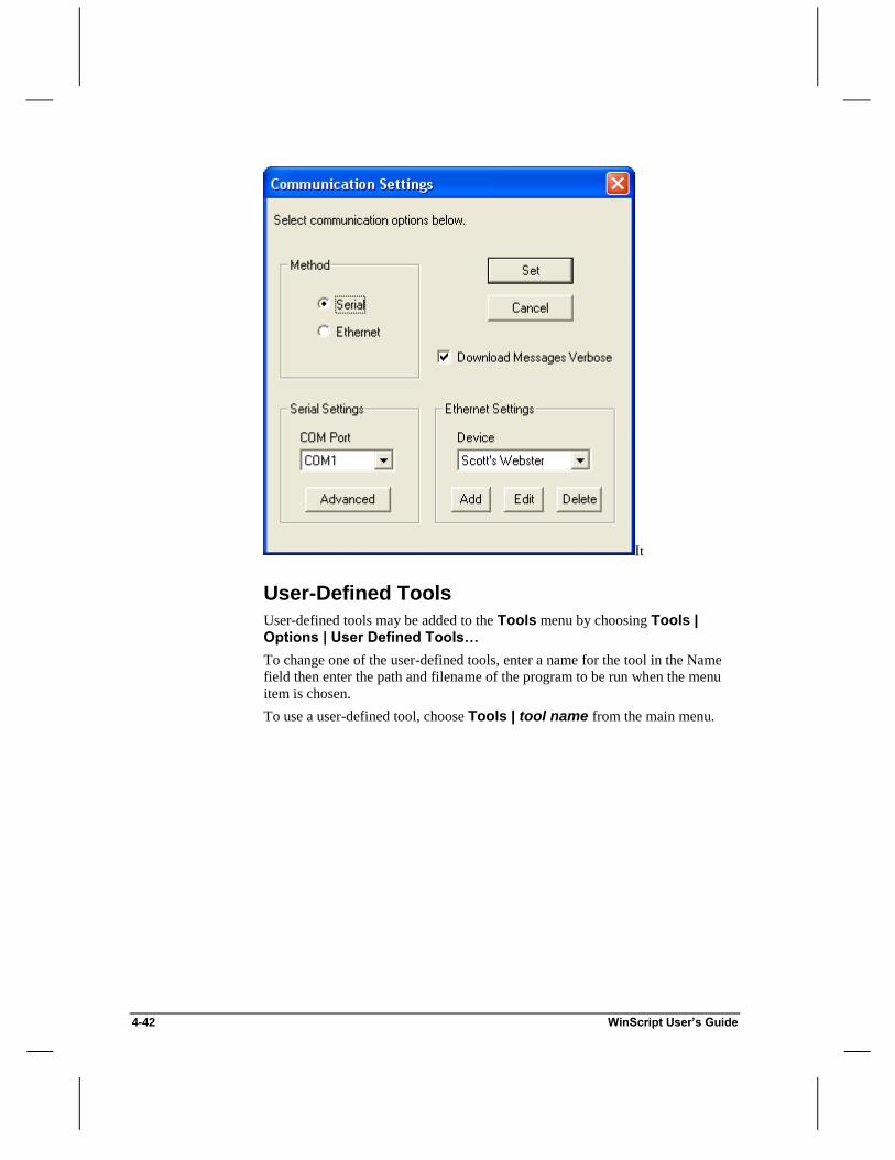
4-42 WinScript User’s Guide
It
User-Defined Tools
User-defined tools may be added to the Tools menu by choosing Tools | Options | User Defined Tools…
To change one of the user-defined tools, enter a name for the tool in the Name
field then enter the path and filename of the program to be run when the menu
item is chosen.
To use a user-defined tool, choose Tools | tool name from the main menu.

WinScript User’s Guide 4-43
Win
Scri
pt
Gu
ide
Tip To create a shortcut for a user-defined tool, place an ampersand (&) before
a letter in the name of the tool. When you wish to use the tool while scripting,
press ALT+T+letter (where letter is the character following the ampersand).

4-44 WinScript User’s Guide

Event Reference 5-1
Even
t
Refe
ren
ce
Event Reference
Sequence events control all of the activities of the Show Controller including
Output states, Serial Ports, the flow of sequences, and even other Show
Controllers. In this chapter you’ll find:
Descriptions, syntax and examples of Discrete, Logical, Program Control,
and LCD Display events.
Descriptions and syntax of common Serial Events for controlling external
serial devices.

5-2 Event Reference
Types of Events There are several "types" of events from which to choose. Events can control
resources internal to the Show Controller (Flags, Sequences, LCD), resources
connected to the Show Controller (Outputs, Serial Ports), or even resources in
another Show Controller.
Discrete Events – Control Outputs in a local or remote Show Controller.
Logical Events – Control Flags and State Variables in a local or remote Show
Controller.
Program Control Events – Control Sequences, and logical "branching"
within sequences.
LCD Display Events – Display custom messages on the LCD.
Built-In Serial Events – Send State Variable values, DMX Ramp commands,
or custom serial messages out a Serial Port.
In addition to these built-in event types, Alcorn McBride Show Controllers are
infinitely extensible as far as Serial Events are concerned. By creating your own
Protocol Files, you can actually expand the language of your Show Controller.
We ship WinScript with a selection of useful Protocol Files. Here are just a few:
MIDI Events – Control MIDI devices from your Show Controller's MIDI port.
SMPTE Events – Serially control an Alcorn McBride SMPTE Machine.
Digital Video Machine Events – Control video playback and drive selection
in an Alcorn McBride Digital Video Machine.
Digital Binloop Events – Control audio/video playback and SMPTE
generation in an Alcorn McBride Digital Binloop.
Internal vs. External Events Events that control resources inside the "local" Show Controller (the one you are
currently scripting) are called Internal Events. Events that control resources
inside a "remote" Show Controller (connected to the local Show Controller via a
serial port) are called External Events.
All Discrete, Logical, LCD Display, and Program Control events can be used as
External events (with the exception of the branching instructions Nop, Goto,
IfOn, IfOff, IfVarEQ, IfVarGE, IfVarGT, IfVarNE, IfVarLT, and IfVarLE).
To change the syntax of an event from Internal to External, move all required
parameters one Data column to the right (e.g. if a parameter is in the Data1
column, move it to the Data2 column) and type the name of the Serial Port
connected to the remote Show Controller in the Data1 column.

Event Reference 5-3
Even
t
Refe
ren
ce
Note For a port to accept External events, it must be configured with AMI Product Wizard as an Alcorn McBride Show Controller (see Communicating
With Alcorn McBride Show Controllers in Chapter 4). Choose Resources | Ports… to configure a port.
Example – Internal Event Syntax
Event Data1 Data2 Data3
On Output1
Turns on Output1 in the local Show Controller.
Example – External Event Syntax
Event Data1 Data2 Data3
On Port2 Output1
Turns on Output1 in a remote Show Controller connected to Port2.
Note If you did not configure the Serial Port connected to the remote Show
Controller using AMI Product Wizard, you will need to replace any remote
resource names with their corresponding Index Numbers.

5-4 Event Reference
Discrete Events Discrete Events utilize discrete relay contact closures (or lamp drivers in some
Show Controllers).
To Do This… Use This Event…
Turn on an Output On
Turn off an Output Off
Toggle the state of an Output Toggle
Continuously blink an Output at a constant rate Blink
Pulse an Output for a user-defined length of time Pulse
Set a group of eight Outputs to a binary value OutPort
Read a group of eight Inputs to a state variable InPort
On Turns on an Output. The Output remains on until another event modifies its
state.
Event Syntax
Event Data1
On Name of Output
Off Turns off an Output. The Output remains off until another event modifies its
state.
Event Syntax
Event Data1
Off Name of Output
Toggle Toggles the state of an Output. If the Output is currently on, it will be turned
off. If the Output is currently off, it will be turned on.
Event Syntax
Event Data1
Toggle Name of Output

Event Reference 5-5
Even
t
Refe
ren
ce
Blink Blinks an Output. Blinking an Output causes it to turn on (for the specified
Blink Time) and off (for the specified Blink Time) continuously until reset by an
Off, On, Pulse, OutPort, or Toggle event.
Event Syntax
Event Data1 Data2
Blink Name of Output Blink Time*
*The Blink Time should be in Seconds.Frames (e.g. 4.15) and can have a maximum value
of 255 frames (8.15 max @ 29.97 and 30 fps; 10.15 max @ 23.976 and 24 fps; 10.05 max @ 25 fps).
Example
Event Data1 Data2
Blink Output1 1.15
Blinks Output1 with a Blink Time of 1.15 (one second, fifteen frames). This
means that if Output1 is currently "off", it will turn on for 1.15 and then off for
1.15 repeatedly until reset by another Discrete Control event.
Pulse Pulses an Output. If the Output is currently on, it will be turned off for the
specified Pulse Length and then on again. If the Output is currently off, it will
be turned on for the specified Pulse Length and then off again.
Event Syntax
Event Data1 Data2
Pulse Name of Output Pulse Length*
*The Pulse Length should be in Seconds.Frames (e.g. 4.15) and can have a maximum
value of 255 frames (8.15 max @ 29.97 and 30 fps; 10.15 max @ 23.976 and 24 fps; 10.05 max @ 25 fps).
Example
Event Data1 Data2
Pulse Output3 2.00
Pulses Output3 (assume it is currently "off") with a Pulse Length of 2.00 (two
seconds). This means that Output3 will turn on for 2.00 and then off again.

5-6 Event Reference
OutPort Sets a group of eight Outputs to a single binary value (0-255). The lowest
number Output becomes the Least Significant Bit (or LSB), the highest becomes
the Most Significant Bit (or MSB).
Event Syntax
Event Data1 Data2
OutPort Output Bank* Desired Literal Value (0-255)
*Bank1 = Outputs 1-8; Bank2 = Outputs 9-16; Bank3 = Outputs 17-24; Bank4 = Outputs 25-32
Example
Event Data1 Data2
OutPort Bank1 157
Sets output bank 1 (Outputs 1-8) to the binary representation of 157 (or
10011101). After the OutPort event is executed, the following outputs are
actuated:
1 2 3 4 5 6 7 8
InPort – (New in version 6.36) Reads a group of eight inputs to a state variable. The lowest number input
becomes the LSB, etc.
Event Syntax
Event Data1 Data2
InPort Input Bank* Name of State Variable
*Bank1 = Inputs 1-8; Bank2 = Inputs 9-16; Bank3 = Inputs 17-24; Bank4 = Inputs 25-32
Example
Event Data1 Data2
InPort Bank1 Var7
Sets var7 to the value of input bank 1 (inputs 1-8). Assuming inputs of
10011101 (where 1 is on), after the InPort event is executed, Var7 will contain
the value 157.

Event Reference 5-7
Even
t
Refe
ren
ce
Logical Events Logical Events utilize Flags and State Variables in a local or remote Show
Controller.
To Do This… Use This Event…
Turn on a flag On
Turn off a flag Off
Toggle the state of a flag Toggle
Add a value to a State Variable AddVar
Subtract a value from a State Variable SubVar
Set the value of a State Variable SetVarEQ
Save a State Variable to non-volatile memory SaveVar
Recover a State Variable from non-volatile memory RestoreVar
On Turns on a Flag. The Flag remains on until another event modifies its state.
Event Syntax
Event Data1
On Name of Flag
Off Turns off a Flag. The Flag remains off until another event modifies its state.
Event Syntax
Event Data1
Off Name of Flag
Toggle Toggles the state of a Flag. If the Flag is currently on, it will be turned off. If
the Flag is currently off, it will be turned on.
Event Syntax
Event Data1
Toggle Name of Flag

5-8 Event Reference
AddVar Adds a value to a State Variable. This value can be a constant value (0-255) or
another State Variable.
Event Syntax
Event Data1 Data2
AddVar Name of State Variable Constant value (0-255) <or>
Name of another State Variable
SubVar Subtracts a value from a State Variable. This value can be a constant value (0-
255) or another State Variable.
Event Syntax
Event Data1 Data2
SubVar Name of State Variable Constant value (0-255) <or>
Name of another State Variable
SetVarEQ Sets the value of a State Variable to a constant value (0-255) or to the value of
another State Variable.
Event Syntax
Event Data1 Data2
SetVarEQ Name of State Variable Constant value (0-255) <or>
Name of another State Variable
SaveVar – (New in version 6.35) Stores the value of a state variable in non-volatile memory so that it can be
recovered, even after power cycling, using RestoreVar.
Event Data1
SaveVar Name of State Variable
RestoreVar – (New in version 6.35) Recovers the value of a state variable from non-volatile memory.
Event Data1
RestoreVar Name of State Variable

Event Reference 5-9
Even
t
Refe
ren
ce
Program Control Events Program Control Events can be used to control the flow of your show. Program
Control Events include events for controlling Sequences in a local or remote
Show Controller. Events are also included for performing conditional branching
within a sequence based on State Variable values and/or Input/Output/Flag
states.
To Do This… Use This Event…
Start a Sequence Start
Stop a Sequence Reset
Pause a Sequence at the current event Stop
Stop a looping Sequence after the last event Pause
Unconditionally jump over events Goto
Jump over events if an Input, Output, or Flag is "on" IfOn
Jump over events if an Input, Output, or Flag is "off" IfOff
Jump over events if a State Variable is equal to a
constant value or the value of another State Variable IfVarEQ
Jump over events if a State Variable is greater than a
constant value or the value of another State Variable IfVarGT
Jump over events if a State Variable is greater than or
equal to a constant value or the value of another State
Variable
IfVarGE
Jump over events if a State Variable is less than a
constant value or the value of another State Variable IfVarLT
Jump over events if a State Variable is less than or
equal to a constant value or the value of another State Variable
IfVarLE
Jump over events if a State Variable is not equal to a
constant value or the value of another State Variable IfVarNE
Set a dummy placeholder for a branch event Nop

5-10 Event Reference
Start Starts a sequence. If the sequence is not currently running and was never paused
in the middle by a Stop event, the sequence will begin execution at the first
event. If the sequence started was running and is now stopped by some other
sequence, the sequence started will resume execution at the event. If the
sequence started is currently running and the setup for the sequence has Restart
Enabled, the sequence will stop event execution and restart execution from the
first event. If the sequence started is currently running and does not have
Restart Enabled, it will continue running as it was and the start event will be
ignored.
Event Syntax
Event Data1
Start Sequence Name
Stop Stops a sequence at the current event. A Start event will cause the sequence to
resume from the point at which it was stopped.
Event Syntax
Event Data1
Stop Sequence Name
Pause Causes a looping sequence to stop looping after the last event. If the sequence is
restarted, it starts execution from the first event.
Event Syntax
Event Data1
Pause Sequence Name
Reset Stops a sequence immediately. If the sequence is restarted, it starts execution
from the first event.
Event Syntax
Event Data1
Reset Sequence Name
Goto Unconditionally jumps over events. Only forward jumps are allowed.

Event Reference 5-11
Even
t
Refe
ren
ce
Note A branch event causes no change in time within the sequence; all events
occur based on time from sequence start.
Event Syntax
Label Time Event Data1 Data2
00:00.00 Goto Event Label
00:00.00 Skipped Events
Event Label 00:00.00 Some Event
Example
Label Time Event Data1 Data2 Data3
00:00.00 IfVarEQ ShowVar 1 RunShow1
00:00.00 IfVarEQ ShowVar 2 RunShow2
00:00.00 Goto End
RunShow1 00:00.00 Start GoShow1
00:00.00 Goto End
RunShow2 00:00.00 Start GoShow2
End 00:00.00 Nop
If ShowVar is not a valid number, the first Goto is reached and the sequence jumps to the
end and performs no action. If ShowVar is equal to 1, "Show 1" is started, then the second Goto event causes the sequence to jump over the "Show 2" events.
IfOn, IfOff Conditionally jumps over events based on the state of an Input, Output, or Flag.
Only forward jumps are allowed.
IfOn -- Jumps over events if an Input, Output, or Flag is "on".
IfOff -- Jumps over events if an Input, Output, or Flag is "off".
Note A branch event causes no change in time within the sequence; all events
occur based on time from sequence start.

5-12 Event Reference
Event Syntax
Label Time Event Data1 Data2
00:00.00 Event Name Name of Input,
Output, or Flag
Event Label
00:00.00 Skipped Events
Event Label 00:00.00 Some Event
Example
Label Time Event Data1 Data2
00:00.00 IfOn NightModeFlag End
00:00.00 Play Ldp1
End 00:00.00 Nop
The Play event is skipped if the system is in Night Mode.
IfVarEQ, IfVarNE, IfVarGT, IfVarGE, IfVarLE, IfVarLT Conditionally jumps over a group of events based on the value of a State
Variable.
IfVarEQ -- Jumps over events if the value of a State Variable is equal to a
constant value (0-255) or the value of another State Variable.
IfVarNE -- Jumps over events if the value of a State Variable is not equal to
a constant value (0-255) or the value of another State Variable.
IfVarGT -- Jumps over events if the value of a State Variable is greater than
a constant value (0-255) or the value of another State Variable.
IfVarGE -- Jumps over events if the value of a State Variable is greater
than or equal to a constant value (0-255) or the value of another State
Variable.
IfVarLE -- Jumps over events if the value of a State Variable is less than or
equal to a constant value (0-255) or the value of another State Variable.
IfVarLT -- Jumps over events if the value of a State Variable is less than
equal to a constant value (0-255) or the value of another State Variable.

Event Reference 5-13
Even
t
Refe
ren
ce
Event Syntax
Label Time Event Data1 Data2 Data3
00:00.00 Event Name State
Variable
Constant value
(0-255) <or>
another State Variable
Event Label
00:00.00 Skipped Events
Event Label 00:00.00 SomeEvent
Example #1
Label Time Event Data1 Data2 Data3
00:00.00 IfVarGE ShowVar 5 End
00:00.00 Play Ldp1
End 00:00.00 Nop
The Play event is skipped if ShowVar 5.
Example #2
Label Time Event Data1 Data2 Data3
00:00.00 AddVar ShowVar 1
00:00.00 IfVarLE ShowVar 100 End
00:00.00 SetVarEQ ShowVar 0
End 00:00.00 Nop
This sequence adds one to ShowVar and then sets it back to 0 if it greater than 100.
Nop Used as a branch placeholder. “Nop” stands for “No Operation”.
Event Syntax
Event Data1
Nop
Example
Label Time Event Data1 Data2 Data3
00:00.00 IfVarEQ ShowVar 5 End
00:00.00 Play Ldp1
End 00:00.00 Nop

5-14 Event Reference
LCD Display Events LCD Display Events display custom text messages as well as Flag and Variable
states on the LCD.
To Do This… Use This Event…
Display a custom message on the LCD Display
Store the currently displayed LCD message StoreLCD
Retrieve and display a previously stored LCD message RecoverLCD
Display the state of a group of flags on the LCD ShowFlags
Display the value of a State Variable on the LCD ShowVar
Display Displays a custom message on the LCD Display.
Note When using the Display event as an External Event, the LCD message
must reside in the local Show Controller.
Event Syntax
Event Data1
Display Name of LCD String <or> Literal Message*
Tip For more information on entering LCD Strings and special syntax for
displaying State Variable values and positioning text within the LCD, see
Chapter 4, pages 6-7.
Example #1
Event Data1
Display DayModeMsg
Displays: My Show: Day Mode
If DayModeMsg is:

Event Reference 5-15
Even
t
Refe
ren
ce
Example #2
Event Data1
Display "My Show: Night Mode ",h0D," "
Displays:
My Show: Night Mode
StoreLCD Stores both lines of text currently displayed on the LCD. Text may be recovered
at any time by using RecoverLCD.
Event Syntax
Event Data1
StoreLCD
RecoverLCD Re-displays both lines of text previously stored by StoreLCD. If no text was
previously stored, the Show Controller version number is displayed.
Event Syntax
Event Data1
RecoverLCD

5-16 Event Reference
ShowFlags Displays the status of one bank of flags on the LCD Display.
Event Syntax
Event Data1
ShowFlags Flag Bank*
* Bank1 = Flags 1-16; Bank2 = Flags 17-32
Example
Event Data1
ShowFlags Bank1
Displays: Flag Bank # 1
1001011000011110
If these flags are "on": 1 2 3 4 5 6 7 8 9 10 11 12 13 14 15 16
ShowVar Displays the value of a State Variable on the LCD Display.
Event Syntax
Event Data1
ShowVar Name of State Variable
Example
Event Data1
ShowVar MainShowVar
Displays: State Variable #
1 = 125
If the index number of MainShowVar is 1, and the current value is 125.

Event Reference 5-17
Even
t
Refe
ren
ce
Built-In Serial Events Built-In Serial Events send a custom message or a specially formatted value of a
State Variable out a Serial Port.
To Do This… Use This Event…
Send a custom serial message out a port MessageOut
Send the value of a State Variable formatted as an
ASCII Decimal out a port SendAsciiDec
Send the value of a State Variable formatted as an
ASCII Hexadecimal out a port SendAsciiHex
Send the value of a State Variable formatted as an
ASCII Octal out a port SendAsciiOct
Send the value of a State Variable out a port as one
binary byte SendVar
Set the value of a State Variable in another Show
Controller equal to the value of a local State Variable PutVar
Ramp a DMX Channel DMXRamp
Generate a Break level on a serial port Break
MessageOut Sends a custom serial message out one of the serial ports. The message is sent
in the protocol defined for that port, but the Show Controller will not wait for an
ACK or other response.
Important Extra bytes may be added by the Show Controller to the front
and/or rear of the message depending on the protocol selected for that port.
Event Syntax
Event Data1 Data2
MessageOut Name of Port Name of Data String or Literal Message*
*See “Entering Data Strings” in Section 4-8.
Example #1
Event Data1 Data2
MessageOut Port3 DataMsg
Sends: h4C h56 h00 h0D
If DataMsg is: h4C h56 h00 h0D

5-18 Event Reference
Example #2
Event Data1 Data2
MessageOut Port3 h4C h56 h00 h0D
Sends: h4C h56 h00 h0D
MessageOutVar MessageOutVar functions just like MessageOut only it has the ability to send
variable values within the custom message. This operates the same way as
displaying variables with LCD Strings, only with a few minor differences.
Simply precede the variable index with an hF3 for an ASCII Value, hF4 for a
right justified value with leading zeros, or hF5 for a Binary byte value. In
instances where you want to send the actual values hF3, hF4, or hF5 simply
double them as in example #4.
Example #1 – ASCII Value
Event Data1 Data2
MessageOutVar Port3 "Executed " hF3 h01 " times" h0D
(Where “4” is the current value of Var1)
Sends (ASCII) : "Executed 4 times" h0D
Example #2 – Leading Zeros
Event Data1 Data2
MessageOut Port3 "Executed " hF4 h01 " times" h0D
(Where “21” is the current value of Var1)
Sends (ASCII) : "Executed 021 times" h0D
Example #3 – Byte Value
Event Data1 Data2
MessageOut Port3 h49 hF5 h01
(Where “37” is the current decimal value of Var1)
Sends: h49 h25

Event Reference 5-19
Even
t
Refe
ren
ce
Example #4 – Actual Value
Event Data1 Data2
MessageOut Port3 h04 hF3 hF3 h80 h0D
Sends: h04 hF3 h80 h0D
Important: This feature can be extremely useful for writing protocol files that
you want to send variable values. If the "Supported" field in the command you
create is at least 6.40 Winscript will automatically implement this new feature.
See the User-Defined Serial Protocols section for more details.
SendAsciiDec, SendAsciiHex, SendAsciiOct Sends an ASCII formatted State Variable out a serial port. The output data can
also be formatted to include leading zeros or spaces (either leading or trailing)
by inserting an optional formatting code in the Data3 column.
SendAsciiDec -- Sends the value of a State Variable formatted as an
ASCII Decimal ("000"-"255"). For example, if the State Variable holds the
Decimal value 23, the Show Controller will send ‘h32 h33’ (or “23”) out
the port. SendAsciiDec sends a maximum of three characters.
SendAsciiHex -- Sends a State Variable out a serial port formatted as an
ASCII Hexadecimal ("00"-"FF"). For example, if the State Variable holds
the Hexadecimal value A5, the Show Controller will send ‘h41 h35’ (or
“A5”) out the port. SendAsciiHex sends a maximum of two characters.
SendAsciiOct -- Sends a State Variable out a serial port formatted as an
ASCII Octal ("000"-"377"). For example, if the State Variable holds the
Octal value 13, the Show Controller will send ‘h31 h33’ (or “13”) out the
port. SendAsciiOct sends a maximum of two characters.
Event Syntax
Event Data1 Data2 Data3
Event Name Name of
Port
Name of State
Variable
Optional Formatting
Code*
*LZ = Leading Zeros; LS = Leading Spaces; TS = Trailing Spaces
Example #1
Event Data1 Data2 Data3
SendAsciiDec Port3 ShowVar
Sends: h31 h32 h33
If the value of ShowVar is decimal 123.

5-20 Event Reference
Example #2
Event Data1 Data2 Data3
SendAsciiHex Port3 ShowVar LZ
Sends: h30 h44
If the value of ShowVar is h0D.
Example #3
Event Data1 Data2 Data3
SendAsciiOct Port3 ShowVar TS
Sends: h31 h33 h20
If the value of ShowVar is octal 13.
SendVar Sends the value of a State Variable out a serial port as one binary byte.
Event Syntax
Event Data1 Data2
SendVar Name of Port Name of State Variable
Example
Event Data1 Data2
SendVar Port3 ShowVar
Sends: h31
If the value of ShowVar is decimal 49.
PutVar Sets the value of a State Variable in another Show Controller equal to the value
of a local State Variable.
Event Syntax
Event Data1 Data2 Data3 Data4
PutVar Name of Port Unit Address of
Remote Show Controller
Name of
Remote State Variable*
Name of
Local State Variable
* To address a remote Show Controller resource by its name, configure the port using
AMI Product Wizard.

Event Reference 5-21
Even
t
Refe
ren
ce
Example
Event Data1 Data2 Data3 Data4
PutVar Port3 2 SlaveShowVar ShowVar
Sets "SlaveShowVar", located in a remote Show Controller connected to Port3, equal to
the value of "ShowVar", a local State Variable.
DMXRamp Sets a DMX dimmer to a given value over a given period of time.
Event Syntax
Event Data1 Data2 Data3
DMXRamp Channel
Number (1-512)
Final Value* Optional Ramp Duration**
*Final Value can be in Percent (0% - 100%), Decimal (0 - 255) or Hex (h00 - hFF).
**The Ramp Duration should be in Minutes:Seconds.Frames (e.g. 03:04.15) and can
have a maximum value of 65535 frames (36:26.20 max @ 29.97 and 30 fps; 45:30.15
max @ 23.976 and 24 fps; 43:41.10 max @ 25 fps). If no ramp duration is entered, the channel is immediately set to the final value.
Example
Event Data1 Data2 Data3
DMXRamp 250 35% 02:06.15
Ramps DMX channel 250 to 35% brightness over a period of two minutes, six seconds,
and fifteen frames.
Break – (New in version 6.35) Sends a Break on the specified serial port. Break is not “queued”, so wait until
all previous data has finished transmitting before it is issued. Special warning:
Since frame 0 and 1 of a sequence are really the same, and since serial messages
are synchronized using a one frame delay, if you put a Msgout at frame 0 and a
Break at frame 1, the break will actually occur first! A standard SMPTE break is
17-21 bits at the current data rate. At 38.4K baud this corresponds to a Data2
value of 2. For 9600 baud use a value of 8.
Event Syntax
Event Data1 Data2 Data3 Data4
Break Name of Port Duration of break in
multiples of 250 usec

5-22 Event Reference
MIDI Events MIDI Events send standard MIDI control messages out a MIDI port (or any
other port configured for the MIDI protocol).
To Do This… Use This Event…
Send a MIDI "Note On" message out a port NoteOn
Send a MIDI "Note Off" message out a port NoteOn
Send a MIDI "Program Change" message out a port ProgramChange
Send a MIDI "Control Change" message out a port ControlChange
NoteOn Sends a MIDI “Note On” message out a MIDI port (or any serial port configured
for the MIDI protocol). To turn off a MIDI note, set the Note Velocity to 0.
Event Syntax
Event Data1 Data2 Data3 Data4
NoteOn Port Name Channel Number
(1-16)
Note Number
(0-127)
Note Velocity
(0-127)*
*A Note Velocity of 0 is equivalent to a “Note Off”.
ControlChange Sends a MIDI “Control Change” message out a serial port.
Event Syntax
Event Data1 Data2 Data3 Data4
ControlChange Port Name
Channel
Number
(1-16)
Control
Change Value
(0-127)
Controller Number (0-127)
ProgramChange Sends a MIDI “Program Change” message out a serial port.
Event Syntax
Event Data1 Data2 Data3
ProgramChange Port Name
Channel Number (1-16)
Program Change Value (0-127)

Event Reference 5-23
Even
t
Refe
ren
ce
SMPTE Serial Events SMPTE events control SMPTE timecode in an Alcorn McBride SMPTE
Machine or Digital Binloop.
Note To use SMPTE Events, you will need to manually configure the protocol
of the port to Alcorn McBride SMPTE Machine or Alcorn McBride Digital Binloop.
To Do This… Use This Event…
Set the current SMPTE time in an Alcorn McBride
SMPTE Machine or Digital Binloop SetSMPTETime
Start Reading/Generating SMPTE in an Alcorn
McBride SMPTE Machine or Digital Binloop EnableSMPTE
Stop Reading/Generating SMPTE in an Alcorn
McBride SMPTE Machine or Digital Binloop DisableSMPTE
Pause SMPTE generation at the current frame in an
Alcorn McBride SMPTE Machine or Digital Binloop PauseSMPTE
SetSMPTETime Sets the current SMPTE time to a new value. If currently generating SMPTE,
the time will immediately jump to the new value, otherwise a subsequent
EnableSMPTE event will start SMPTE generation from the new time. If the
SMPTE Machine or Digital Binloop is configured to read SMPTE, the event is
ignored.
Event Syntax
Event Data1 Data2
SetSMPTETime Name of Port connected
to SMPTE Machine or Digital Binloop
Time to Generate
From*
*Time to Generate From should be in HH:MM:SS.FF, with leading zeros (e.g.
04:23:35.15).
Example
Event Data1 Data2
SetSMPTETime SMPTEPort 12:23:00.00
Sets current SMPTE time to 12:23:00.00

5-24 Event Reference
EnableSMPTE Starts SMPTE reading/generation. Generation begins from the current SMPTE
time in the SMPTE Machine. If the SMPTE Machine is already generating or
reading SMPTE, the event is ignored.
Event Syntax
Event Data1
EnableSMPTE Name of Port connected to SMPTE Machine or
Digital Binloop
DisableSMPTE Stops SMPTE reading/generation. If SMPTE is already stopped, the event is
ignored.
Event Syntax
Event Data1
DisableSMPTE Name of Port connected to SMPTE Machine or
Digital Binloop
PauseSMPTE Pauses SMPTE generation at the next loop point. A subsequent EnableSMPTE
event will resume SMPTE from the start frame.
Event Syntax
Event Data1
PauseSMPTE Name of Port connected to SMPTE Machine or
Digital Binloop
IdleSMPTE Freezes SMPTE generation at the current frame. A subsequent EnableSMPTE
event restarts generation from the start frame.
Event Syntax
Event Data1
IdleSMPTE Name of Port connected to SMPTE Machine or Digital
Binloop

Event Reference 5-25
Even
t
Refe
ren
ce
LightCue Serial Events LightCue events control DMX recording, cue selection, and playback in an
Alcorn McBride LightCue. For more information about these and other
functions of the LightCue, please consult the LightCue User’s Guide.
Note To use LightCue Events, you will need to configure the protocol of the
port to Alcorn McBride LightCue.
To Do This… Use This Event…
Select a cue SelectCue
Play the currently selected cue Play
Play and loop the currently selected cue PlayAndLoop
Begin recording DMX to a cue Record
Play the currently selected cue, jam-syncing to SMPTE ChasePlay
Map DMX input to DMX output, without recording FeedThrough
Pile-on additional cues to the current cue PileOn
Pile-on additional cues to the current cue and loop PileOnAndLoop
Clear a cue in a currently playing pile-on ClearCue
Still the currently playing cue at the current look Still
Stop all currently playing cues and hold the last look Reset
SelectCue Selects which cue should be played when a Play command is received.
Event Syntax
Event Data1 Data2
SelectCue Name of Port connected to
LightCue
Cue Number (1-511)

5-26 Event Reference
Play Plays the currently selected cue. If a crossfade time is entered into Data2, the
current look will crossfade into the currently selected cue during the specified
crossfade time. If no cue is currently selected, an optional cue number may be
placed in Data2, with a corresponding crossfade time placed in Data3. If there
is no currently selected cue and Data2 does not contain a valid cue number, cue
#1 is played immediately without a crossfade.
Event Syntax
Event Data1 Data2 Data3
Play Name of Port
connected to LightCue
Optional Cue
Number <or> Crossfade Time*
Crossfade Time*
* Crossfade Time should be in HH:MM:SS.FF, with leading zeros (e.g. 04:23:35.15).
PlayAndLoop Plays and loops the currently selected cue. If a crossfade time is entered into
Data2 , the current look will crossfade into the currently selected cue during the
specified crossfade time. If no cue is currently selected, an optional cue number
may be placed in Data2 , with a corresponding crossfade time placed in Data3 .
If there is no currently selected cue and Data2 does not contain a valid cue
number, cue #1 is played immediately without a crossfade. When the cue has
finished playing, it loops back to the beginning.
Event Syntax
Event Data1 Data2 Data3
PlayAndLoop Name of Port
connected to LightCue
Optional Cue
Number <or>
Crossfade Time*
Crossfade
Time*
* Crossfade Time should be in HH:MM:SS.FF, with leading zeros (e.g. 04:23:35.15).
Record Begins recording a valid incoming DMX stream to the specified cue.
Event Syntax
Event Data1 Data2
Record Name of Port connected to LightCue
Cue Number

Event Reference 5-27
Even
t
Refe
ren
ce
ChasePlay Plays a cue, jam-synced to SMPTE. If a chase offset is entered into Data2, and
a crossfade time is entered into Data3, the current look will crossfade into the
currently selected cue during the specified crossfade time - when the incoming
SMPTE timecode reaches the specified chase offset. This effectively overrides
the SMPTE start trigger embedded into a cue number when it is recorded. If no
cue is currently selected, an optional cue number may be placed in Data2, with
a corresponding chase offset placed in Data3, and a corresponding crossfade
time placed in Data4. If there is no currently selected cue and Data2 does not
contain a valid cue number or chase offset, cue #1 is selected for SMPTE-
triggered playback without a crossfade.
Event Syntax
Event Data1 Data2 Data3 Data4
ChasePlay Name of Port
connected to
LightCue
Optional Cue
Number <or>
Chase Offset HH:MM:SS.FF*
Chase Offset
HH:MM:SS.FF*
<or> Crossfade
Time HH:MM:SS.FF*
No Parameter <
or> Crossfade
Time HH:MM:SS.FF*
* Crossfade Time and Chase Offset should be in HH:MM:SS.FF, with leading zeros (e.g.
04:23:35.15).
FeedThrough Patches the DMX Input to the DMX Output, without recording to a cue.
Event Syntax
Event Data1 Data2
FeedThrough Name of Port connected to
LightCue
PileOn Causes the LightCue to play a new cue simultaneously with other currently
playing cues. Up to 6 cues may be piled-on at one time. Each of the 512
channel values of each cue that is playing is compared against the corresponding
channel in the other playing cues, and the highest value is output. A separate
PileOn event is needed for each cue. Cues may be removed from a pile-on by
using the ClearCue event.
Event Syntax
Event Data1 Data2
PileOn Name of Port connected to
LightCue
Cue Number

5-28 Event Reference
PileOnAndLoop Causes the LightCue to play a new cue simultaneously with other currently
playing cues. Up to 6 cues may be piled-on at one time. Each of the 512
channel values of each cue that is playing is compared against the corresponding
channel in the other playing cues, and the highest value is output. A separate
PileOn event is needed for each cue. Cues may be removed from a pile-on by
using the ClearCue event. As each cue ends, it is individually looped back to
the beginning.
Event Syntax
Event Data1 Data2
PileOnAndLoop Name of Port connected to
LightCue
Cue Number
ClearCue Clears a cue from a currently playing pile-on.
Event Syntax
Event Data1 Data2
ClearCue Name of Port connected to LightCue
Cue Number
Still Stills playback at the current look. A subsequent Play command will restart
playback from the current look.
Event Syntax
Event Data1 Data2
Still Name of Port connected to
LightCue
Reset Stops playback, holding the current look.
Event Syntax
Event Data1 Data2
Reset Name of Port connected to
LightCue

Event Reference 5-29
Even
t
Refe
ren
ce
Digital Video Machine Serial Events Digital Video Machine events control video playback and clip/drive selection in
an Alcorn McBride Digital Video Machine. For more information about these
and other functions of the Digital Video Machine, please consult the Digital
Video Machine User’s Guide.
Note To use Digital Video Machine Events, you will need to configure the
protocol of the port to Alcorn McBride Digital Video Machine.
To Do This… Use This Event…
Select a clip SelectClip
Select the Internal/Removable drive for playback SelectDrive
Play the currently selected clip Play
Play and loop the currently selected clip PlayAndLoop
Still video playback at the current position Still
SelectClip Selects which clip should be played when a Play command is received.
Event Syntax
Event Data1 Data2
SelectClip Name of Port connected to
Digital Video Machine
Clip Number (1-511)
SelectDrive Selects which drive should play back the currently selected clip when a Play
command is received.
Event Syntax
Event Data1 Data2
SelectDrive Name of Port connected to
Digital Video Machine
Internal <or>
Removable

5-30 Event Reference
Play Plays the currently selected clip (or any other clip) from the currently selected
drive. If no clip is currently selected and Data3 does not contain a valid clip
number, the first clip on the currently selected drive is played.
Event Syntax
Event Data1 Data2
Play Name of Port connected to
Digital Video Machine
Optional Clip
Number
PlayAndLoop Plays the currently selected clip (or any other clip) from the currently selected
drive. When the clip has finished playing, it is restarted. If no clip is currently
selected and Data3 does not contain a valid clip number, the first clip on the
currently selected drive is played and looped.
Event Syntax
Event Data1 Data2
PlayAndLoop Name of Port connected to
Digital Video Machine
Optional Clip
Number
Still Stills playback at the current position. A subsequent Play command will restart
playback from the current position.
Event Syntax
Event Data1 Data2
Still Name of Port connected to
Digital Video Machine

Event Reference 5-31
Even
t
Refe
ren
ce
Digital Binloop Serial Events Digital Binloop events control audio/video playback in an Alcorn McBride
Digital Binloop (SMPTE generate/read events for the Digital Binloop are
discussed in the SMPTE Serial Events section, earlier in this reference). Some
versions of the Digital Binloop support additional events. For more information
about these and other functions of the Digital Binloop, please consult the Digital
Binloop User’s Guide.
Note To use Digital Binloop Events, you will need to configure the protocol of
the port to Alcorn McBride Digital Binloop.
To Do This… Use This Event…
Play a sound/video clip from a reproducer or group of
reproducers Play
Play and loop a sound/video clip from a reproducer or
group of reproducers PlayAndLoop
Pause audio/video playback from a reproducer or group
of reproducers Pause
Mute audio playback from a reproducer or group of
reproducers Mute
Play a SMPTE or Video-synchronized sound/video clip
from a reproducer or group of reproducers SPlay
Play and loop a SMPTE or Video-synchronized
sound/video clip from a reproducer or group of reproducers
SPlayAndLoop
Un-Mute audio playback from a reproducer or group of
reproducers UnMute
Play Plays a sound or video clip from a reproducer or group of reproducers.
Event Syntax
Event Data1 Data2 Data3 Data4
Play Name of Port
connected to
Digital Binloop
Reproducer
Number
(R1-R16)
<or>
Group
Number
(G1-G13) <or> "All"
"Primary"
socket <or>
"Secondary"
socket <or>
"Consecutive" sockets
Sound/Video
Clip Number
(1-511)

5-32 Event Reference
Example
Event Data1 Data2 Data3 Data4
Play Binloop1 R2 Primary 10
Plays clip 10 from Reproducer 2, Primary Socket.
PlayAndLoop Plays a sound or video clip from a reproducer or group of reproducers. When
the clip has finished playing, it is restarted.
Event Syntax
Event Data1 Data2 Data3 Data4
PlayAndLoop Name of
Port
connected
to Digital Binloop
Reproducer
Number
(R1-R16)
<or>
Group
Number
(G1-G13) <or> "All"
"Primary"
socket <or>
"Secondary"
socket <or>
"Consecutive" sockets
Sound/Video
Clip Number
(1-511)
Example
Event Data1 Data2 Data3 Data4
PlayAndLoop Binloop1 All Consecutive 5
Plays and loops clip 5 from all Reproducers, first from Primary then Secondary sockets.
Pause Pauses audio/video playback at the current position. A subsequent Play
command will restart playback from the current position.
Event Syntax
Event Data1 Data2
Pause Name of Port connected to
Digital Binloop
Reproducer Number
(R1-R16) <or> Group
Number (G1-G13)
<or> "All"
Example
Event Data1 Data2 Data3 Data4
Pause Binloop1 G3
Pauses all Reproducers in Group 3.

Event Reference 5-33
Even
t
Refe
ren
ce
Mute Mutes audio playback from a reproducer or group of reproducers.
Event Syntax
Event Data1 Data2
Mute Name of Port connected to
Digital Binloop
Reproducer Number
(R1-R16) <or> Group
Number (G1-G13)
<or> "All"
UnMute Un-Mutes audio playback from a reproducer or group of reproducers.
Event Syntax
Event Data1 Data2
UnMute Name of Port connected to
Digital Binloop
Reproducer Number
(R1-R16) <or>
Group Number (G1-G13) <or> "All"
SPlay Plays a sound or video clip from a reproducer or group of reproducers. Audio
playback is frame-synchronized to a SMPTE or Composite Video Sync signal.
Event Syntax
Event Data1 Data2 Data3 Data4
SPlay Name of Port
connected to
Digital Binloop
Reproducer
Number
(R1-R16)
<or>
Group
Number
(G1-G13) <or> "All"
"Primary"
socket <or>
"Secondary"
socket <or>
"Consecutive"
sockets
Sound/Video
Clip Number (1-511)
Example
Event Data1 Data2 Data3 Data4
SPlay Binloop1 R2 Primary 10
Plays clip 10 from Reproducer 2, Primary Socket synchronized to Video Sync or SMPTE.

5-34 Event Reference
SPlayAndLoop Plays a sound or video clip from a reproducer or group of reproducers. When
the clip has finished playing, it is restarted. Audio playback is frame-
synchronized to a SMPTE signal.
Event Syntax
Event Data1 Data2 Data3 Data4
SPlayAndLoop Name of
Port
connected
to Digital Binloop
Reproducer
Number
(R1-R16)
<or>
Group
Number
(G1-G13) <or> "All"
"Primary"
socket <or>
"Secondary"
socket <or>
"Consecutive"
sockets
Sound/Video
Clip Number (1-511)

Event Reference 5-35
Even
t
Refe
ren
ce
Other Serial Device Events WinScript supports almost any serial device automatically by using a Protocol
(or PCL) file. PCL files contain all the information WinScript needs to create
device-specific events that send command messages to the external device.
When you configure a port for a device’s protocol, WinScript loads the PCL file
and adds the new events to Event Wizard.
WinScript ships with a standard group of PCL files (including the SMPTE,
DVD, Digital Video Machine, and Digital Binloop PCL files described in the
above sections) that support many common devices. You can use these PCL
files as is, customize them, or create your own (for more information, see
Appendix A). As always, you can download new or updated PCL files from our
home page (www.alcorn.com).
For an up-to-date list of all PCL files currently installed on your PC (and
individual listings of all their events and parameters), choose Tools | Protocol Editor from the WinScript main menu.


Advanced WinScript Programming 6-1
Ad
van
ced
Pro
gra
mm
ing
Advanced WinScript Programming
In this section, one of our experienced show programmers takes you through
several common techniques for efficiently scripting a complex show by
combining Show Controller resources and clever algorithms. You’ll find such
tips as:
Synchronized video playback from multiple sources.
Extending the life span of show equipment by using Day and Night Modes.
Creating “randomized” sequences
Creating a real-time clock.
Tight control of show elements.

6-2 Advanced WinScript Programming
Introduction This section is designed to illustrate some advanced techniques of script
programming that we have come to rely upon as the most robust and
straightforward way of utilizing our equipment in shows.
Terms Used
The term “PC or Program Counter” is used to refer to the current event that each
sequence is on. If it is at the top of the sequence, it means that the PC is
pointing to the first event. It could be anywhere between the top of the sequence
and the last event. The PC advances every time the event it is pointing to has
event time equal to (or prior to) the TC, described below. At that time, it
executes the event. The PC can only move forward in the sequence. It will
automatically move to the next event when the last is completed, or it can jump
forward.
The term “TC or Time Counter” is used to refer to the current time in frames
that each sequence is at. The TC always starts at zero when the PC is at the top
of the sequence, meaning that the time is 00:00.00 when each sequence begins
running. The TC increments one frame every time the Show Controller
advances one frame, and does not change based upon the time any event is set
to. Any time that the TC encounters an event that has a time less than or equal
to it, the event is executed on that frame. The TC always moves forward, and
does so as long as the sequence is running. If the event being executed is an
external serial command that takes longer than one frame to execute, the TC
continues to move forward during that time.
Although these techniques apply to all Alcorn McBride Show Controllers, most
of these examples assume that the controller is a V16+, unless indicated
otherwise.
Finally, even though all of the examples in this section are written for
WinScript, the scripting strategy involved is exactly the same for DOS Script.
Most users should be able to reformat these examples for use in any version of
DOS Script or WinScript.

Advanced WinScript Programming 6-3
Ad
van
ced
Pro
gra
mm
ing
Get Control of Your Sequences When scripting a show, the show normally flows from beginning to end in a
straightforward manner, chronologically. However, there are times when the
normal show flow is halted abruptly, and changed to some other condition. If
the change is not handled properly, two problems could occur. The first is when
things start happening when they’re not supposed to, and the second when
things won’t happen when they’re supposed to.
When things happen on their own, it’s usually because sequences are running
that you didn’t know were running. I often get phone calls from people who say
“My show ran fine all day long, but when I put it in Night Mode it started
running again all by itself 20 minutes later”.
When things don’t happen when they’re supposed to, it’s usually because the
sequence you’re trying to run is already running. If Restart is not enabled in the
setup for that sequence, it won’t run if it’s already running. I will hear “My
show is supposed to loop over and over again. It runs fine the first time, but
won’t loop and run again.”
The solution to both problems is to make sure all sequences that could be
running are reset when the abrupt change occurs. This is especially important
for looping sequences, which never stop running until they are reset. What I do
for an absolute guarantee is to have a ResetAllSequences sequence that resets all
sequences (except the one that calls ResetAllSequences of course). Sometimes I
will not reset tiny sequences that are short in time, and don’t run other
sequences, but this can be attributed to laziness. Here is an example of
ResetAllSequences:
After calling ResetAllSequences, it is a good idea to wait a few frames before
doing anything else, to give all events that were running in those sequences time
to settle, especially serial commands to external devices like players. This is
shown in the following sequence, AbruptHaltToShow:
AbruptHaltToShow Label Time Event Data1 Data2 Data3 Comment
00:00.00 Start ResetAllSequences
00:00.02 Still dvm1
00:00.02 Still DVM
00:00.02 Still dvm3
ResetAllSequences Label Time Event Data1 Data2 Data3 Comment
00:00.00 Reset DayMode
00:00.00 Reset NightMode
00:00.00 Reset WaitLdps
00:00.00 Reset StartShow
00:00.00 Reset PreShow
00:00.00 Reset MainShow
00:00.00 Reset PostShow
00:00.00 Reset Maintenance

6-4 Advanced WinScript Programming
Day and Night Mode Most shows that only run during a portion of the day should have a Day and
Night mode of operation. There is no reason to have audio, video, lighting
effects, etc. playing all night long. It can reduce the life of the equipment, be
very annoying, and even be potentially hazardous if there is no operator
supervision.
The best approach for a show that doesn’t have some other computer to tell the
Show Controller when to go to Daymode or Nightmode is to have a button
perform the function. It is better to have one button toggle between Daymode
and Nightmode than to have two buttons because you can potentially confuse
the Show Controller if the two buttons are pushed near the same time, unless
you go to great programming lengths to prevent it. Here are some sequences
that explain how to use one button for both Daymode and Nightmode:
SelectDayorNightMode Label Time Event Data1 Data2 Data3 Comment
00:00.00 Start ResetAllSequences
00:00.02 IfOff GoingDayFlag GoDay
GoNight 00:00.02 Start NightMode Go to
Sleep
00:00.02 Goto End
GoDay 00:00.02 Start DayMode Wake Up
End 00:00.02 Toggle GoingDayFlag Flip Flag
DayMode Label Time Event Data1 Data2 Data3 Comment
00:00.00 Display GoingToDayModeMsg
00:00.00 Start Spinupdvm1
00:00.00 Start SpinupDVM
00:00.00 Start Spinupdvm3
00:00.00 Start TurnLightsOn
00:00.00 Start GoBGM
00:00.00 Display AtDayModeMsg
NightMode Label Time Event Data1 Data2 Data3 Comment
00:00.00 Display GoingToNightModeMsg
00:00.00 Start Spindowndvm1
00:00.00 Start SpindownDVM
00:00.00 Start Spindowndvm3
00:00.00 Start TurnLightsOff
00:00.00 Start OffBGM
00:00.00 Display AtNightModeMsg

Advanced WinScript Programming 6-5
Ad
van
ced
Pro
gra
mm
ing
Synchronized Scripting More often than not, our Show Controllers interface to multiple digital video
players at one time. When these players are commanded to play
unsynchronized, there is little concern with timing. Here is an example of two
unsynchronized video players.
AutoExec (Autostart Enabled) Label Time Event Data1 Data2 Data3 Comment
00:00.00 Search Dvm1 1
00:00.00 Search DVM 2
00:00.00 Start LeftKiosk
00:00.00 Start RightKiosk
LeftKiosk (Looping Enabled) Label Time Event Data1 Data2 Data3 Comment
00:00.00 Play dvm1 Presentation On Chess
02:05.12 Search dvm1 1 Loop Presentation
RightKiosk (Looping Enabled) Label Time Event Data1 Data2 Data3 Comment
00:00.00 Play DVM Presentation on Checkers
01:34.25 Search DVM 2 Loop Presentation
Synchronized Video Playback
When Digital Video Machines are asked to output video and audio together, it is
important that they are commanded to play simultaneously in order to achieve
frame-to-frame synchronization of audio and video.
The following sequence causes the second player to play after the first, which
causes unsynchronized playback. Even though the Play events happen on the
same frame, the first Play event may take a frame or two for the Show
Controller to send out the serial play message. The DVM will begin playing,
return an Acknowledge, and only then can the second Play event begin to occur,
throwing the sync out the window.
UnSynchronized Label Time Event Data1 Data2 Data3 Comment
00:00.00 Play dvm1
00:00.00 Play DVM
The following sequences show the correct way to script this. The serial
messages will go out both ports simultaneously, and the players will begin
playing in synchronization.
Synchronized Label Time Event Data1 Data2 Data3 Comment
00:00.00 Start PlayDVM1
00:00.00 Start PlayDVM
PlayDVM1 Label Time Event Data1 Data2 Data3 Comment
00:00.00 Play dvm1

6-6 Advanced WinScript Programming
PlayDVM Label Time Event Data1 Data2 Data3 Comment
00:00.00 Play DVM
Synchronized Searching
Although synchronized playback is the only required element in order for the
show to perform correctly, synchronized searching is almost always required.
Unsynchronized searching in most show scenarios takes too long. It is much
better for the players to begin and end searching at about the same time. Here is
an example of unsynchronized searching.
Unsynchronized Label Time Event Data1 Data2 Data3 Comment
00:00.00 Search Dvm1 1
00:00.00 Search DVM 2
00:00.00 Search Dvm3 3
00:00.00 Search Dvm4 4
00:00.00 Search Dvm5 5
00:05.00 Start MainShow Go Play ‘Em
Depending on which video player you are using, this could take forever! For
our purposes, let’s say that the searches take one second each. This sequence
will take five seconds to complete. If the audience is in the theatre while these
searches take place, this is unacceptable! Here is an example of synchronous
searching. This sequence will complete in one second. Much better!
Synchronized Label Time Event Data1 Data2 Data3 Comment
00:00.00 Start MainSearch1
00:00.00 Start MainSearch2
00:00.00 Start MainSearch3
00:00.00 Start MainSearch4
00:00.00 Start MainSearch5
00:01.00 Start MainShow Go Play ‘Em
MainSearch1 Label Time Event Data1 Data2 Data3 Comment
00:00.00 Search Dvm1 1
MainSearch2 Label Time Event Data1 Data2 Data3 Comment
00:00.00 Search DVM 2
MainSearch3 Label Time Event Data1 Data2 Data3 Comment
00:00.00 Search Dvm3 3
MainSearch4 Label Time Event Data1 Data2 Data3 Comment
00:00.00 Search Dvm4 4
MainSearch5 Label Time Event Data1 Data2 Data3 Comment
00:00.00 Search Dvm5 5

Advanced WinScript Programming 6-7
Ad
van
ced
Pro
gra
mm
ing
Searching As Quickly As Possible
The above examples show you how to search all players at the same time,
instead of one after the other, to save time. Using that method you still allow
enough time for the searches to take place before issuing the Play commands.
Sometimes you just can’t afford to wait a moment longer than you have to
because you don’t want the audience to see the show lag due to the searches. To
reduce this lag to an absolute minimum, use the following sequences. This
method uses flags to determine when all the searches are done, even if some
take longer than others. These sequences add a lot of code to your script, but
you have to do what you have to do.
SynchronizedAndFast Label Time Event Data1 Data2 Data3 Comment
00:00.00 Off Dvm1Done
00:00.00 Off DVMDone
00:00.00 Off Dvm3Done
00:00.00 Off Dvm4Done
00:00.00 Off Dvm5Done
00:00.00 Start MainSearch1
00:00.00 Start MainSearch2
00:00.00 Start MainSearch3
00:00.00 Start MainSearch4
00:00.00 Start MainSearch5
00:00.00 Start WaitForSearches
MainSearch1 Label Time Event Data1 Data2 Data3 Comment
00:00.00 Search dvm1 1
00:00.00 On DVM1Done
MainSearch2 Label Time Event Data1 Data2 Data3 Comment
00:00.00 Search DVM 2
00:00.00 On DVMDone
MainSearch3 Label Time Event Data1 Data2 Data3 Comment
00:00.00 Search dvm3 3
00:00.00 On DVM3Done
MainSearch4 Label Time Event Data1 Data2 Data3 Comment
00:00.00 Search dvm4 4
00:00.00 On DVM4Done
MainSearch5 Label Time Event Data1 Data2 Data3 Comment
00:00.00 Search dvm5 5
00:00.00 On DVM5Done
WaitForSearches (Looping Enabled) Label Time Event Data1 Data2 Data3 Comment
00:00.00 IfOff DVM1Done TryAgain
00:00.00 IfOff DVMDone TryAgain
00:00.00 IfOff DVM3Done TryAgain

6-8 Advanced WinScript Programming
00:00.00 IfOff DVM4Done TryAgain
00:00.00 IfOff DVM5Done TryAgain
00:00.00 Start MainShow Go Play ‘Em
00:00.02 Pause WaitForSearches Stop Checking
TryAgain 00:00.00 Nop
Modularity Modularity is a word you probably thought you'd only hear in programmers'
circles. Well, in many ways, scripting is in fact programming; many of the same
concepts apply. Modularity is an attempt to place programming code in
appropriate sections that make sense. If you were making a “House” program,
you would have a “Kitchen” module with code in it that applied to kitchen
appliances, and a “Bathroom” module with code that applied to bathroom
appliances. You would not want your “blender” code residing in your Bathroom
module. It makes it hard to read, hard to understand, and most importantly, hard
to change later. That is, unless you make margaritas in your bathroom’s jet spa!
Script programming is much simpler than real computer language programming,
but scripts can become large and unwieldy too, so modularity begins to play a
bigger importance, as your scripts become more complex.
Let’s assume that we are asked to program a script for a "Zoo Animals" pre-
show that has five video segments all coming off the same DVD player, being
shown to an audience on ten different monitors where all the monitors display
the same video. Let’s further assume that the pre-show is started manually by
an operator, after the audience has filled the pre-show area. We will use a V4+
for this job. For simplicity, we’ll also assume a frame rate of 30 frames per
second, even though the players really run at 29.97.
Note When working with a real show such as this one, always use the exact
frame rate of the players, projectors, or whatever media source you are using.
Even miniscule differences in frame rate can have a profound impact on the
quality of your show.

Advanced WinScript Programming 6-9
Ad
van
ced
Pro
gra
mm
ing
Our “Zoo Animals” video segments have the following properties:
Segment Name Length (mm:ss.ff)
1 Monkeys 02:46.20
2 Elephants 00:33.10
3 Tigers 01:40.00
4 Democrats 02:46.20
5 Zoo Summary 05:33.10
Non-Modular Approach
This approach searches and plays the five segments in order in one sequence
called MainShow. MainShow is started by Input9, which is an external button
that is pushed by an operator on an OCC console. The delay between Search
and Play commands is necessary to wait for the searches to take place. If the
delay were not put in, the Play command, which would not start until after the
Search was completed, would occur at the wrong time; effectively ruining the
segment.
Although this sequence works, it has some undesirable qualities. The
mandatory two second wait for searches to take place means that guests will be
forced to watch a two second pause in their show, instead of the minimum time
it takes to actually perform the searches, which could be as low as one frame. In
addition, the programmer had to figure out the playing time of each segment,
and if a segment is added or deleted, or a segment is shortened or lengthened,
the programmer will have to re-calculate those Search and Play times every
time a change is made to the show.
MainShow (Start Trigger: Button 1) Label Time Event Data1 Data2 Data3 Comment
00:00.00 Search dvm1 1 Monkey Segment
00:02.00 Play dvm1 Wait 2 seconds for search
02:48.20 Search dvm1 2 Elephant Segment
02:50.20 Play dvm1 Wait 2 seconds for search
03:24.00 Search dvm1 3 Tiger Segment
03:26.00 Play dvm1 Wait 2 seconds for search
05:06.00 Search dvm1 4 Democrat Segment
05:08.00 Play dvm1 Wait 2 seconds for search
07:54.20 Search dvm1 5 Summary Segment
07:56.20 Play dvm1 Wait 2 seconds for search
13:30.00 Search dvm1 1 Search to Black- Done!
Modular Approach #1
This approach breaks up the show into six sequences, one of which is the trigger
sequence, and the rest are dedicated to individual video segments. It has the
advantage of having search times that occur as fast as possible, without any
delay required. The Start event will happen whenever the search is completed,
but since the sequence it starts resets the event time back to zero, the events
occur at the appropriate time regardless of how long the searches take. The

6-10 Advanced WinScript Programming
programmer has only to enter the play times once, and their the length of each
segment, so no calculation needs to be done. In addition, this approach makes it
easy to add or remove segments by changing the search frames and reconnecting
which sequence starts any other sequence. It does have one disadvantage,
though: The programmer must look through all the sequences to analyze the
flow of the show, whereas the non-modular approach lets the programmer see
the whole show at a glance.
This method is how most Script programmers create their shows.
MainShow (Start Trigger: Input 9) Label Time Event Data1 Data2 Data3 Comment
00:00.00 Search dvm1 1 Monkey Segment
00:00.00 Start Monkey
Monkey Label Time Event Data1 Data2 Data3 Comment
00:00.00 Play dvm1
02:46.20 Search dvm1 2 Elephant Segment
02:46.20 Start Elephant
Elephant Label Time Event Data1 Data2 Data3 Comment
00:00.00 Play dvm1
00:33.10 Search dvm1 3 Tiger Segment
00:33.10 Start Tiger
Tiger Label Time Event Data1 Data2 Data3 Comment
00:00.00 Play dvm1
01:40.00 Search dvm1 4 Democrat Segment
01:40.00 Start Democrat
Democrat Label Time Event Data1 Data2 Data3 Comment
00:00.00 Play dvm1
02:46.20 Search dvm1 5 Summary Segment
02:46.20 Start Summary
Summary Label Time Event Data1 Data2 Data3 Comment
00:00.00 Play dvm1
05:33.10 Search dvm1 1 Video Black-Done!
Modular Approach #2
This approach also breaks up the show into six sequences, one of which is the
trigger sequence, and the rest are dedicated to individual video segments. The
flow of the show can be seen by looking at MainShow, yet all the time
programming still occurs in the individual sequences. The searches are all as
fast as possible. The programmer has only to enter the beginning and ending
frame numbers of each video segment, and adding segments or changing the
order is simply a matter of changing MainShow! The two frame delay
between segments in MainShow allow the individual sequences time to pause
MainShow. Since ScriptOS is a multi-tasking operating system, MainShow
would start all video segments at once if there was no brief delay.

Advanced WinScript Programming 6-11
Ad
van
ced
Pro
gra
mm
ing
This method is how I design shows.
MainShow (Start Trigger: Input 9) Label Time Event Data1 Data2 Data3 Comment
00:00.00 Search dvm1 1 Monkey Segment
00:02.00 Start Monkey
00:02.02 Start Elephant
00:02.04 Start Tiger
00:02.06 Start Democrat
00:02.08 Start Summary
00:02.10 Search dvm1 1 Video Black-Done!
Monkey Label Time Event Data1 Data2 Data3 Comment
00:00.00 Stop MainShow Freezes MainShow time
00:00.00 Search dvm1 1 Monkey Segment
00:00.00 Play dvm1 2
00:00.00 Start MainShow UnFreezes MainShow
Elephant Label Time Event Data1 Data2 Data3 Comment
00:00.00 Stop MainShow Freezes MainShow time
00:00.00 Search dvm1 2 Elephant Segment
00:00.00 Play dvm1 3
00:00.00 Start MainShow UnFreezes MainShow
Tiger Label Time Event Data1 Data2 Data3 Comment
00:00.00 Stop MainShow Freezes MainShow time
00:00.00 Search dvm1 3 Tiger Segment
00:00.00 Play dvm1 4
00:00.00 Start MainShow UnFreezes MainShow
Democrat Label Time Event Data1 Data2 Data3 Comment
00:00.00 Stop MainShow Freezes MainShow time
00:00.00 Search dvm1 4 Democrat Segment
00:00.00 Play dvm1 5
00:00.00 Start MainShow UnFreezes MainShow
Summary Label Time Event Data1 Data2 Data3 Comment
00:00.00 Stop MainShow Freezes MainShow time
00:00.00 Search dvm1 5 Summary Segment
00:00.00 Play dvm1 6
00:00.00 Start MainShow UnFreezes MainShow
Randomization The only reasonable way to do randomization is to increment a state variable
once per frame, letting it wrap at 256, continuously, and then checking the value
when a random number is desired. Since the increment of a state variable once
per frame is predictable when you look at the value at normalized intervals (i.e.
the value is 34 at frame 0, and if you check again at frame 30 it’s 64), you will
only get truly random numbers if you check based upon a non-timed, random
event. For example, if you check the variable when an operator pushes a button,

6-12 Advanced WinScript Programming
that will generate a good random number because the operator could push the
button any time, and will never push it twice at the same time. The following
sequence will generate a random number:
Random (Autostart Enabled; Looping Enabled) Label Time Event Data1 Data2 Data3 Comment
00:00.00 AddVar RandomVar 1 increment RandomVar
The following sequences will get a random number when an operator pushes a
button attached to input9. The desired range of random numbers is 0 - 9, so we
will have to trim it down from 0 - 255.
GetRandom (Start Trigger: Input9) Label Time Event Data1 Data2 Data3 Comment
00:00.00 SetVarEQ MyVar RandomVar
00:00.00 Start ForceRange
ForceRange Forces MyVar to be in range 0-9; (Looping Enabled) Label Time Event Data1 Data2 Data3 Comment
00:00.00 IfVarLE MyVar 9 if <= 9, we’re done
00:00.00 SubVar MyVar 9
00:00.00 Goto End Do it again Sam
Done 00:00.00 Start GotRandom
00:00.02 Nop wait 2 frames here
End 00:00.00 Nop loop here
GotRandom Random number now in range 0-9; (Looping Enabled) Label Time Event Data1 Data2 Data3 Comment
00:00.00 Reset ForceRange Don’t Loop Anymore
00:00.00 Nop Use MyVar Here
Now let's take these sequences, and add them to our Zoo Animals show above to
show an example of randomization. Assume the Art Director wants the first
four video segments to play at random, not allowing any segment to play more
than once, and then play the summary.
We can’t get a random number four times for two reasons. One, only the first
random number will be truly random, because it is based upon an operator
pressing a button, the remaining three random numbers would all be gotten at a
predictable time after the first one was gotten. Second, if we get four random
numbers, we could get a random number to play a segment we’ve already
played. Checking to see if we have already played a segment, and choosing
another one if so would force us to write way too many sequences. The correct
approach is to get one random number when the operator presses the button,
thereby guaranteeing it is a truly random number, and then using that one
number to determine what order all four segments will be shown in. The
maximum combinations of four selections, each with one unique position are 24.
We’ll also use the Modular Approach #2 for this job. This example shows how
useful the approach can be.
Random (Autostart Enabled; Looping Enabled) Label Time Event Data1 Data2 Data3 Comment
00:00.00 AddVar RandomVar 1 increment RandomVar

Advanced WinScript Programming 6-13
Ad
van
ced
Pro
gra
mm
ing
StartShow Takes random number from button push; (Start trigger: Input9) Label Time Event Data1 Data2 Data3 Comment
00:00.00 SetVarEQ MyVar RandomVar
00:00.00 Start ForceRange
ForceRange Forces MyVar to be in range 0-23; (Looping Enabled) Label Time Event Data1 Data2 Data3 Comment
00:00.00 IfVarLE MyVar 23 Done if <= 23, we’re done
00:00.00 SubVar MyVar 23
00:00.00 Goto End Do it again Sam
Done 00:00.00 Start MainShow
00:00.02 Nop wait 2 frames
End 00:00.00 Nop loop here
MainShow Pick order of video segments from random number Label Time Event Data1 Data2 Data3 Comment
00:00.00 Reset ForceRange
00:00.00 IfVarEq MyVar 0 Random1 Decides order
00:00.00 IfVarEq MyVar 1 Random2
00:00.00 IfVarEq MyVar 2 Random3
00:00.00 IfVarEq MyVar 3 Random4
00:00.00 IfVarEq MyVar 4 Random5
00:00.00 IfVarEq MyVar 5 Random6
00:00.00 IfVarEq MyVar 6 Random7
00:00.00 IfVarEq MyVar 7 Random8
00:00.00 IfVarEq MyVar 8 Random9
00:00.00 IfVarEq MyVar 9 Random10
00:00.00 IfVarEq MyVar 10 Random11
00:00.00 IfVarEq MyVar 11 Random12
00:00.00 IfVarEq MyVar 12 Random13
00:00.00 IfVarEq MyVar 13 Random14
00:00.00 IfVarEq MyVar 14 Random15
00:00.00 IfVarEq MyVar 15 Random16
00:00.00 IfVarEq MyVar 16 Random17
00:00.00 IfVarEq MyVar 17 Random18
00:00.00 IfVarEq MyVar 18 Random19
00:00.00 IfVarEq MyVar 19 Random20
00:00.00 IfVarEq MyVar 20 Random21
00:00.00 IfVarEq MyVar 21 Random22
00:00.00 IfVarEq MyVar 22 Random23
00:00.00 IfVarEq MyVar 23 Random24
00:00.00 Display ErrorMsg Never get here
00:00.00 Goto End
Random1 00:00.02 Start Monkey Order 1, 2, 3, 4
00:00.04 Start Elephant
00:00.06 Start Tiger
00:00.08 Start Democrat
00:00.10 Goto Summary
Random2 00:00.02 Start Monkey Order 1, 2, 4, 3
00:00.04 Start Elephant
00:00.06 Start Democrat
00:00.08 Start Tiger
00:00.10 Goto Summary
Random3 00:00.02 Start Monkey Order 1, 3, 2, 4
00:00.04 Start Tiger
00:00.06 Start Elephant

6-14 Advanced WinScript Programming
00:00.08 Start Democrat
00:00.10 Goto Summary
…Etc… Random24 00:00.02 Start Democrat Order 4, 3, 2, 1
00:00.04 Start Tiger
00:00.06 Start Elephant
00:00.08 Start Monkey
Summary 00:00.12 Start Summary Always done here
00:00.14 Search dvm1 1 Video Black-Done!
Monkey Label Time Event Data1 Data2 Data3 Comment
00:00.00 Stop MainShow Freezes MainShow time
00:00.00 Search dvm1 1 Monkey Segment
00:00.00 Play dvm1 2
00:00.00 Start MainShow UnFreezes MainShow
Elephant Label Time Event Data1 Data2 Data3 Comment
00:00.00 Stop MainShow Freezes MainShow time
00:00.00 Search dvm1 2 Elephant Segment
00:00.00 Play dvm1 3
00:00.00 Start MainShow UnFreezes MainShow
Tiger Label Time Event Data1 Data2 Data3 Comment
00:00.00 Stop MainShow Freezes MainShow time
00:00.00 Search dvm1 3 Tiger Segment
00:00.00 Play dvm1 4
00:00.00 Start MainShow UnFreezes MainShow
Democrat Label Time Event Data1 Data2 Data3 Comment
00:00.00 Stop MainShow Freezes MainShow time
00:00.00 Search dvm1 4 Democrat Segment
00:00.00 Play dvm1 5
00:00.00 Start MainShow UnFreezes MainShow
Summary Label Time Event Data1 Data2 Data3 Comment
00:00.00 Stop MainShow Freezes MainShow time
00:00.00 Search dvm1 5 Summary Segment
00:00.00 Play dvm1 6
00:00.00 Start MainShow UnFreezes MainShow
As you can see, randomization can add a lot of sequences and events to your
script, but if you design it properly ahead of time, you can make your code
modular, flexible, and elegant.
Real Time Clock It is often desirable to have events occur at chronological times during the day.
Our Show Controllers do not have internal real time clocks; however, there are
two ways to accomplish this task. The first is to use an external Real Time
Clock module, which transmits the current time to our equipment via serial port
once per second. This device is accurate to a few seconds a year, and doesn’t

Advanced WinScript Programming 6-15
Ad
van
ced
Pro
gra
mm
ing
forget what time it is when the power is turned off in a power outage. The
second solution is to simulate a Real Time Clock in ScriptOS. This solution
does have the advantage of being free, but has the disadvantage of being off by
approximately 1 minute per day and forgetting what time it is if the power goes
out. If a standard UPS is used, and some device (or person) resets the time once
per day, these problems can become negligible.
Both solutions write the hour, minute, second, and frame to four state variables.
I will now show you several examples of using the Real Time Clock (either
external or simulated).
Start Event at 8 p.m.
This sequence is started whenever the HourVar reaches 20.
TimeToTapeFriends (Start trigger: HourVar=20) Label Time Event Data1 Data2 Data3 Comment
00:00.00 Start RecordTV Do Whatever
Start Event at 11:58 p.m.
This sequence is started whenever the MinuteVar state variable reaches 58
minutes, and then checks to see if HourVar is 23. If it is, it starts the event, if
not, it exits.
TwoTilMidnight (Start trigger: MinuteVar=58) Label Time Event Data1 Data2 Data3 Comment
00:00.00 IfVarEQ HourVar 23 11:58 Now!
00:00.00 Goto End
11:58 00:00.00 Start DoIt Do Whatever
End 00:00.00 Nop
Start Event Every Hour.
This sequence is started whenever the HourVar state variable changes.
Because sequences always look for edge-triggered occurrences, every time
HourVar is changed, this sequence will run because HourVar will always be
greater or equal to zero.
AtTheHour1 (Start trigger: HourVar0) Label Time Event Data1 Data2 Data3 Comment
00:00.00 Start DoIt Do Whatever
Start Event Three Frames after Every Minute from Midnight to Six a.m.
This sequence is a little hairier, but is again demonstrative of the power of
ScriptOS.

6-16 Advanced WinScript Programming
AtTheHour2 (Start trigger: FrameVar=3) Label Time Event Data1 Data2 Data3 Comment
00:00.00 IfVarEQ SecondVar 0 Minute 3 frames past minute
00:00.00 Goto End
Minute 00:00.00 IfVarGT VarHour 6 End No Good
00:00.00 Start DoIt Do Whatever
End 00:00.00 Nop
Make Sure Event is Running from 10a.m. to 8:30p.m.
Since sequences are edge triggered, it is possible to miss the time something is
supposed to happen if the power goes out while the trigger time occurs. The
power may come back on, with ScriptOS again knowing what time it is ( if you
have the external RTC),but it won’t know that it was supposed to have triggered
something in the past if you write the sequences as we have been.
This sequence is an example of when you have to make sure something is
running during a specific time. If the power goes out, ScriptOS must re-
determine if the event should be occurring. For this example, we will assume
that back ground music for an entire theme park needs to play between 10 a.m.
and 8:30 p.m. We will further assume that when Output3 is on, the BGM is
also.
BGM (AutoStart Enabled; Looping Enabled) Label Time Event Data1 Data2 Data3 Comment
00:00.00 IfVarLT HourVar 10 NoGood It’s before 10 a.m.
00:00.00 IfVarGT HourVar 21 NoGood It’s after 9 p.m.
00:00.00 IfVarEq HourVar 20 Past8 Between 8 and 9 p.m.
00:00.00 Goto BGM_Ok It’s between 10 a.m. and 8 p.m.
Past8 00:00.00 IfVarGE MinuteVar 30 NoGood It’s past 8:30 p.m.
BGM_Ok 00:00.00 On output3 BGM is on
00:00.00 Goto End
NoGood 00:00.00 Off output3 BGM is off
End 00:00.00 Nop
Communications Between Alcorn McBride Equipment
All of our equipment can talk to each other via serial communications using our
own Alcorn 9 Bit Control protocol. This is useful if, for example, one V16+ is
in charge an entire attraction, including the PreShow, and it communicates
serially with two other V16+s that control two mainshows in two independent
theatres. It is also useful for simply adding expansion capabilities, such as
connecting an IO64 to a V16+, where the V16+ is the main Show Controller. In
this scenario, the IO64 adds 32 inputs and outputs to the V16’s existing 16.
Let’s use the IO64 as an I/O expansion box and see what the best way is to
integrate it into your show. For starters, you need to plug a Null modem cable in
between the V16+ and the IO64, using any available serial port (except the

Advanced WinScript Programming 6-17
Ad
van
ced
Pro
gra
mm
ing
Programmer Port) on each box. You also need to select the Alcorn 9 Bit Control
protocol for both of these ports, as well as the same baud rate for both ports.
Since you have to set the baud rate and protocol in the IO64, this automatically
means you have to have two scripts, one for the V16+ and one for the IO64, but
need not program much else in the IO64 if desired.
There are three ways to divide programming between the two boxes. The first is
to program little or no sequences into the IO64, and directly access the I/O of the
IO64 from the V16+. The second is to program as many sequences as needed to
handle the I/O in the IO64, and simple start sequences back and forth between
the two boxes as needed. The third is to utilize a combination of both.
My recommendation is to keep things modular and place as many sequences as
necessary in the IO64. In other words, any programming that interfaces to I/O
in the IO64 should remain in the IO64, and the V16+ can be the main Show
Controller and just talk to the IO64 when necessary. This means the
programming will be more distributed, causing less show memory to be used up
in the V16+. It also makes it more readable because there are fewer sequences
in the V16+ that have anything to do with the IO64. In general, it’s modular.
Here are two example scripts to illustrate this idea. The first is for the V16+, the
second is for the IO64. The IO64 in this case is connected to the entrance and
exit doors and a PLC, which is controlling pyrotechnics.
The doors are simple output signals of the IO64, and the PLC both receives
output signals from the V16+, and sends input signals to the V16+.
As always, don’t forget to configure the IO64 port of the V16+ using AMI
Product Wizard. This allows you to address the IO64’s sequences by their full
names. See Communicating with Alcorn McBride Show Controllers in Chapter
4 for more information.
V16+ Script
StartShow Checks with PLC to see if it’s OK to start show (Start trigger: StartShowButton (Input1)) Label Time Event Data1 Data2 Data3 Comment
00:00.00 Off PLCOkFlag Assume not OK
00:00.00 Start IO64 OKToStart? Start IO64 Seq
00:01.00 If Off PLCOkFlag NotOk If PLC did not
turn on flag
00:01.00 Start MainShow Ok to start show
00:01.00 Goto End
NotOk 00:01.00 Display ErrorMsg Inform operator
End 00:01.00 Nop
StartShow Started externally by IO64 (from PLC) Label Time Event Data1 Data2 Data3 Comment
00:00.00 On PLCOkFlag Now it’s ok to
start show

6-18 Advanced WinScript Programming
MainShow Label Time Event Data1 Data2 Data3 Comment
00:00.00 Start IO64 OpenEntrDoors
01:00.00 Start IO64 CloseEntrDoors
06:03.15 Start IO64 StartPyro1
08:42.23 Start IO64 StartPyro2
09:00.00 Start IO64 OpenExitDoors
10:00.00 Start IO64 CloseExitDoors
IO64 Script
OKToStart? Started externally by V16+ Label Time Event Data1 Data2 Data3 Comment
00:00.00 IfOff PyroOk End Low signal from PLC
00:00.00 Start V16+ StartShow Go turn on PLCOkFlag
End 00:00.00 Nop
OpenEntrDoors Turns off magnet that holds doors shut; Started externally by V16+ Label Time Event Data1 Data2 Data3 Comment
00:00.00 Off EntrMagnet1 Deactivate Door
Electromagnet
00:00.00 Off EntrMagnet2 Deactivate Door
Electromagnet
00:00.00 Off EntrMagnet3 Deactivate Door
Electromagnet
00:00.00 Off EntrMagnet4 Deactivate Door
Electromagnet
CloseEntrDoors Moves doors to close position; Started externally by V16+ Label Time Event Data1 Data2 Data3 Comment
00:00.00 On EntrMagnet1 Hold Door Closed
00:00.00 On EntrMagnet2 Hold Door Closed
00:00.00 On EntrMagnet3 Hold Door Closed
00:00.00 On EntrMagnet4 Hold Door Closed
00:00.00 Pulse EntrMotor1 01.00 Motor Closes Door
00:00.00 Pulse EntrMotor2 01.00 Motor Closes Door
00:00.00 Pulse EntrMotor3 01.00 Motor Closes Door
00:00.00 Pulse EntrMotor4 01.00 Motor Closes Door
StartPyro1 Started externally by V16+ Label Time Event Data1 Data2 Data3 Comment
00:00.00 IfOff PyroOk End Make darn sure again
00:00.00 Pulse GoPyro1 01.00 Pulse for 1 second
End 00:00.00 Nop
StartPyro2 Started externally by V16+ Label Time Event Data1 Data2 Data3 Comment
00:00.00 IfOff PyroOk End Make darn sure again
00:00.00 Pulse GoPyro2 01.00 Pulse for 1 second
End 00:00.00 Nop

Advanced WinScript Programming 6-19
Ad
van
ced
Pro
gra
mm
ing
OpenExitDoors Turns off magnet that holds doors shut; Started externally by V16+ Label Time Event Data1 Data2 Data3 Comment
00:00.00 Off ExitMagnet1
00:00.00 Off ExitMagnet2
00:00.00 Off ExitMagnet3
00:00.00 Off ExitMagnet4
CloseExitDoors Moves doors to close position; Started externally by V16+ Label Time Event Data1 Data2 Data3 Comment
00:00.00 On ExitMagnet1
00:00.00 On ExitMagnet2
00:00.00 On ExitMagnet3
00:00.00 On ExitMagnet4
00:00.00 Pulse ExitMotor1 01.00
00:00.00 Pulse ExitMotor2 01.00
00:00.00 Pulse ExitMotor3 01.00
00:00.00 Pulse ExitMotor4 01.00
ESTOPs and Fire Alarms Although it is IMPERATIVE that our Show Controllers are not used to control
safety critical equipment, it is very useful to have a Show Controller mute audio,
stop video, open doors, and turn on lights, etc. during an emergency situation.
This response is typically actuated when a PLC or some other device sends an
E-Stop or Fire Alarm signal. Here is an example of such a sequence. Note that
the normal condition of the E-Stop input is high, and the V16 will run this
sequence whenever the input goes low, indicating a true emergency. If the input
went low when there was not an emergency, the V16 indicates a failed signal
that would alert the staff that maintenance needs to fix the problem.
E-Stop (Start trigger: EstopInput goes off) Label Time Event Data1 Data2 Data3 Comment
00:00.00 Start ResetAllSeqs
00:00.02 Start KillAudio
00:00.02 Start KillVideo
00:00.02 Start LightsUp
00:00.02 Start OpenAllDoors
Frame Accuracy There are two reasons why execution of sequences may take longer than
expected, or appear to take longer than expected, even though the box is frame
accurate and will execute hundreds of events in one frame.
Serial Events Take Time
Any event that sends a serial message to a device will take at least a frame to
execute, and in many cases, much longer. A Search event on a Alcorn
McBride DVM takes at most a second. A Play event could last for several
minutes. Any sequence that contains an event like this will be frozen in time
until an Acknowledge is received from the player (or other device). The events

6-20 Advanced WinScript Programming
after the external event will not be able to execute until the external event is
finished processing.
The Processor Scans Events like a PLC
ScriptOS is a multi-tasking operating system. This means that it can do several
things at once. Well, it can’t actually do several things at once, but it can do
many, many things in one frame. The processor executes events one sequence
at a time. This process is similar to how a Programmable Logic Controller
works.
ScriptOS performs the following processes in order, once per frame:
1. Process Incoming Serial Messages
2. Process Input Changes to see if there are any sequences that should be
marked to start
3. Process State Variables to see if there are any sequences that should be
marked to start
4. Parse Through List of Running Sequences
Execute any event that matches the current frame time
5. Process Output Changes
6. Increment the Frame
Let me give you some examples of how this affects you:
If you turn on an output, it won’t actually go on the instant the event is
processed. It actually turns on just before the end of the current frame, along
with any other output changes. This means that if you were to turn on an output
and then turn it back off again on the same frame, the output would never
actually turn on at all. The last commanded state of the output before the end of
the frame is used.
OutputDoesntActivate Label Time Event Data1 Data2 Data3 Comment
00:00.00 On output1
00:00.00 Off output1
00:00.00 On output1
00:00.00 Off output1
00:00.00 On output1
00:00.00 Off output1
00:00.00 On output1
00:00.00 Off output1 Never came on
This example probably is a little more useful. If you have an event that tells
another sequence to start, it does not actually start it, but rather, it marks it for
execution. This means that if you start a sequence that is before the one you call
it from, it will not begin execution until the next frame, whereas if you start a
sequence that is after the one you call it from, it will begin execution on the
same frame.
SequenceA Label Time Event Data1 Data2 Data3 Comment
00:00.00 On output2

Advanced WinScript Programming 6-21
Ad
van
ced
Pro
gra
mm
ing
SequenceB Label Time Event Data1 Data2 Data3 Comment
00:00.00 On Output1
00:00.00 Start SequenceA
00:00.00 Start SequenceC
SequenceC Label Time Event Data1 Data2 Data3 Comment
00:00.00 On output3
The result of running SequenceB is that output3 will turn on one the same
frame as output1, and output2 won’t turn on until a frame later. This happens
because SequenceA has already been determined not to be marked for
execution, so the processor then moves on to SequenceB. SequenceB is
marked for execution because that’s the sequence we told to run, so the
processor attempts to process all events that occur on frame zero. Since both
Start events happen on frame zero, they are both processed. The result of them
being processed is that both SequenceA and SequenceC are marked for
execution. The processor then determines that SequenceC is marked for
execution, and executes it. SequenceA is not processed until the processor
starts all over again at the top of the sequence list on the next frame. Easy,
right?
Power up Conditions If your script has any sequences that are Autostart Enabled and do anything
with DVD players, including spinning them up, you should wait at least 25
seconds before attempting to communicate with them in any way. If the Show
Controller is Autostarting, then that must mean that it was previously deprived
of power, which means that it is likely that the rack of video players was also
deprived of power. Whether or not this condition was intentional is not
important. What is important, is that our Show Controllers power up within a
few frames and DVD players take about 25 seconds to “Wake Up”, so you need
to wait before you try to talk to them.
Restart and Restart Lockout Restart Enabling a sequence allows the sequence to start, even though it is
already running. When it does so, it starts over at the beginning with the PC set
to event1 and the TC set to 00:00.00.
Restart Lockout allows a sequence to be restarted, but prevents it from doing
so for a specified amount of frames after it was originally started.
Let’s say you are programming a kiosk in a museum on the “Life of Frogs”.
The guest presses a button, and the guest sees and hears information about frogs.
Normally, the guest watches the entire presentation, and when the presentation
is over, the guest leaves. The sequence that played the presentation has ended.
But suppose the guest got bored during the middle of the presentation and
walked away. Now someone else walks up and wants to hear about frogs ( little
does he know how bored he will be ). This guest does not want to sit through

6-22 Advanced WinScript Programming
the remainder of the previous guests presentation. He wants to be able to press
the button and have the presentation start over from the beginning. Restart allows this.
This is a nice feature. But let’s say that no-one is watching the presentation (It’s
off), and a thirteen year old boy walks up to the kiosk. He starts the
presentation, gets bored within 0.0000015 of a second and out of curiosity
pushes the button again, to find that the presentation starts over. In fact, if he
pushes the button over and over as fast as he can, he can get the frog
presentation to “rap”. This is oh so much more exciting than the presentation
itself. Now people are staring. Restart Lockout allows you to set a number
of frames that the sequence will not restart in. This allows serious guests to be
able to restart the show when they don’t want to watch the last half of the show
first, and it prevents your and my favorite milk shake globbering, paint chipping
teenager from rapping the frogs.
Preventing Glitches Glitches occur when an input of a Show Controller receives a voltage close
enough to the maximum to turn it on, or low enough to ground to turn it off,
even though no person or device intended the signal to do so. This can be
caused by noisy signals or a noisy device transmitter (people are automatically
noisy transmitters in the case of buttons). There are two ways to reduce the
effects of glitches.
The Purpose of an Input or Button
If it’s possible to do so, make each input signal serve only one purpose. If some
computer or PLC somewhere is sending pulses to an input to tell the Show
Controller what to do, the Show Controller could become confused if one pulse
is supposed to tell it to do one thing, and two pulses another. This is possible,
but confusing and dangerous. Likewise, a button on an OCC panel which the
operator is supposed to press several times to mean different things can cause a
problem because the person could accidentally press it the wrong number of
times, by not pressing it solidly each time. You can afford to buy a few more
$90 Allen-Bradley buttons.
I realize that I recommend using one button for Daymode/Nightmode. This is
due to the way that DVD Players react to being spun up and spun down. I’m not
concerned with glitches for Daymode/Nightmode because this button is pushed
when there are no guests in the theatre and likely the building.
Check the Input Again
Even if your inputs only serve one purpose, they can still glitch and cause
inappropriate behavior. The best way to confirm that your input went on, off, or
pulsed, is to check it again. If there was a glitch, it is unlikely that the signal is
still glitching when you check later. Here is an example that checks 10 frames
into a 15 frame pulse to make sure the input is still on.
StartShowNow Starts show on ½ second Input 3 pulse (Start trigger:

Advanced WinScript Programming 6-23
Ad
van
ced
Pro
gra
mm
ing
Label Time Event Data1 Data2 Data3 Comment
00:00.10 IfOff input3 End It must have glitched!
00:00.11 Start MainShow
End 00:00.00 Nop
Tight Control and Awareness In some cases it is not important if a show goes down for short periods of time.
This is especially the case of exhibits or kiosks in museums and the like where
the electronics may be a small part of the overall show. For example, let’s say
your museum has a Pepper's Ghost effect that transforms a wooden cigar store
Indian into a video still of a Native American, and the effect fails during the day.
One of the janitors at closing may leave a message to the maintenance people
that “Elijah went down sometime today”, and the effect will get fixed by
morning.
Most of the time, however, inactive show elements are just not acceptable;
someone needs to be told immediately when all or part of the show fails, so that
it can be brought back up as soon as possible.
Equipment in most shows consists of a main Show Controller and other devices
connected it. With WinScript, tight control of most peripheral devices is quite
easy. If several of our Show Controllers are connected together, awareness of
what all Show Controllers are doing is just as important. If you send a
command to another box, you want to be sure it was carried out.
For example, let’s say you have a V16+ sending light cue commands to a DMX
Machine. The best way to make sure the cue was carried out (the sequence
executed) is to send a message back to the V16+ to confirm it. There are several
ways to do this, but this one seems to be the easiest.
V16+ Script
SendingLightCue Label Time Event Data1 Data2 Data3 Comment
00:00.00 Off ConfirmFlag
00:00.00 Start Dmx Cue3 Run Cue 3
00:00.05 IfOn ConfirmFlag Confirmed
00:00.05 Start Dmx Cue3 Try Again!
00:00.10 IfOn ConfirmFlag Confirmed
Failed! 00:00.10 Start Cue3Failed No good
00:00.00 Goto End
Confirmed 00:00.00 Start Cue3Success Good
End 00:00.00
ConfirmIt Label Time Event Data1 Data2 Data3 Comment
00:00.00 On ConfirmFlag
DMX Script
Cue3 Label Time Event Data1 Data2 Data3 Comment
00:00.00 Start v16+ ConfirmIt Turn on ConfirmedFlag

6-24 Advanced WinScript Programming
00:00.00 DMXRamp 15 50% 02.00 Do Cue 3 Stuff
00:00.00 DMXRamp 241 FF 01.15
00:00.00 DMXRamp 242 FF 01.15
00:00.00 DMXRamp 243 FF 01.15
00:00.00 DMXRamp 69 75%
In this manner, you can check individual commands sent back and forth between
boxes. Sometimes, where you want to know immediately if a Show Controller
has failed, and not wait until a message is sent between them, you can
implement a “Watch Dog Timer”, which will notify a Show Controller if a
subsystem Show Controller has failed. You can even put a watchdog timer in
the subsystem to watch over the main Show Controller. The procedure is the
same.
Here is such an example. If the subsystem IO64 fails entirely, or the serial port
fails, or the cable fails or falls off, the V16 will know about it, and alert some
theme park wide central computer. The V16 could even flash the lights in the
employee bathroom, or log the time of the failure, if a Real Time Clock is
installed.

Advanced WinScript Programming 6-25
Ad
van
ced
Pro
gra
mm
ing
V16+ Script
WatchDogTimer Increments watchdog timer once a frame (Autostart Enabled, Looping Enabled) Label Time Event Data1 Data2 Data3 Comment
00:00.00 AddVar WatchDogVar 1
WatchDogFailed WatchDogVar has reached 60 frames (Start trigger: WatchDogVar GE 60) Label Time Event Data1 Data2 Data3 Comment
00:00.00 Start AlertDACS Announce Failure
IO64 Script
SendImOK Sets V16+’s WatchDogVar to 0 once per second (Autostart Enabled, Looping Enabled) Label Time Event Data1 Data2 Data3 Comment
00:01.00 SetVarEq v16+ 0 WatchDogVar WatchDogVar = 0

6-26 Advanced WinScript Programming

Application Notes 7-1
Application Notes
Alcorn McBride Show Controllers can be used in very simple and very
complex applications. Here are a few sample applications to get you
started.
The Application Notes available in this section are:
Large Theatre Control
Controlling an Alcorn McBride Digital Video Machine
Controlling Automatic Doors

7-2 Application Notes
Large Theatre Control Many large shows are designed in a theatre format. This design provides
high guest throughput by utilizing a PreShow, where guests gather to watch
a short film or audio-animatronic presentation. As these guests are
watching the PreShow, another group of guests is already in the Theatre
watching the main show. The attraction is timed so that when the Preshow
is over and the operator has given any special instructions to the guests, the
automatic entrance doors open. The previous group will have left the
theatre only moments earlier. As the entrance doors close and the main
show starts again, another group of guests is gathering to watch the
Preshow.
This application note discusses the design of a large theatre just like the one
described above. This design utilizes an Alcorn McBride V16+ and several
generic show elements to create a simple, but powerful theatre experience.
The Theatre In Question
Every show design starts with an attraction description. This is where the
desired guest experience, operator interface and performance requirements
come together to create a show equipment list. For our imaginary theatre
we have selected a multi-channel audio film projection theatre and a multi-
screen video preshow area. As with most shows of this type the preshow
and theatre run in relative synchronization, allowing guests to accumulate in
the preshow during the film presentation in the main theatre.
As we shall see, a single V16+ will provide total control of both theatres,
including operator consoles, projector, doors, audio equipment, and the
DVD Players. For the sake of completeness our application also
incorporates some specialty hardware located in the main theatre. In this
instance the V16+ handshakes with a ride control system which sends
motion data to moving seats located in the theatre. In a more generic
installation this could instead control special effects or other show-
synchronized activities within the main theatre.
You can follow along with this application note in WinScript by opening
MYSHOW.AMW (located in the WinScript\Scripts\Examples\ directory).
Note This application note assumes that the reader possesses rudimentary
scripting skills. New users should take the WinScript Tutorial in Chapter 3
before continuing.
Architecture
The V16+ is the ultimate collector of all operator and status inputs and the
distribution point for commands throughout the attraction.

Application Notes 7-3
Inputs, Outputs, Sync and Serial Ports
To begin configuring our V16+ we need to make a list of the inputs and
outputs to which it will be connected. This information will then be entered
into the configuration menus of WinScript.
Digital inputs consist of contact closures or voltage sources throughout the
building which are used to sense the status of remote equipment and
operator pushbuttons. In addition, switches on the V16+ front panel
provide user-defined initialization, test, and special functions.
Digital outputs provide dry contact closures for switching control voltages
throughout the building. These signals can be used to open doors,
illuminate lights, and handshake with other equipment.
Serial connections provide the RS-232 commands and status that permit the
V16+ to control up to sixteen DVD Players.
A Composite Sync connection provides synchronization from any or all of
the DVD Players. This guarantees that the V16+ remains exactly in frame
sync with all DVD Players.
Front Panel Buttons
Our inputs include the first eight front panel buttons of the V16+. We will
use the first switch as a show startup button. This button will bring all of
the external equipment up to its nominal starting condition. The show
startup button will activate the same sequence which will execute
automatically whenever the V16+ is powered up.
An evening shutdown button could perform much the opposite of the show
Startup sequence. It would provide a means to stop the video players, take
projectors off line, and turn off operator prompting.
The other internal buttons have been left unassigned at this point but could
be used for special test features, a way to select a different show cycle or
combination, or almost any other function, limited only by the designer's
imagination.
Theatre OCC
The Theatre OCC must provide a way to start the show and to request that
the show pause at rollover. (Rollover is the point when the projector has
reached the end of the theatre show material, the theatre audience has exited
and the preshow audience is in the process of entering the theatre.) Our
show will be designed to automatically cycle all day long, thereby
encouraging the operators to maintain maximum throughput. However, for
large audiences the operators may require more load time than that provided
in the automatic recycling. The Theatre OCC Pause button allows the
operator to request a pause during this load cycle prior to the next theatre
presentation. We have also provided a Theatre OCC Stop button. This
button's function is to stop a show during an emergency situation. It will
close the projector douser, mute the theatre audio and bring up the
houselights. The Theatre OCC will also have open/close/auto switches for

7-4 Application Notes
the theatre entrance and exit doors. Inputs from these switches do not need
to go to the V16+ in our simple theatre architecture. Although they
certainly could be processed by the V16+, it is sufficient in our application
that the V16+'s door outputs are wired through these switches to provide
automated door opening when these switches are in the auto position.
The Theatre OCC could also be outfitted with an audio mute switch. This
switch allows the operator to request the V16+ to mute the theatre audio
entirely. This switch is often used by maintenance during the test show in
the morning so that they do not have to listen to the entire theatre audio
program.
The designer could even include a PA talk button that allows the operator to
mute the audio system by a predetermined amount and to mix audio from
the Theatre OCC microphone into the amplifiers so that the operator can
provide theatre loading and unloading direction to guests. In our simple
example, this button is routed directly to the audio equipment, although the
V16+ could easily handle it, and perform logical operations upon it.
Show status at both the Theatre and Preshow OCCs is indicated by the cue
light. This light will be illuminated when the system is Ready to run the
next show. This light can also be blinked to serve as a cue for the Preshow
load spiel, end of show warning, etc.
Preshow OCC
The Preshow OCC is simpler than the Theatre OCC and does not require
any switches with inputs going to the V16+. It does have a theatre entrance
door switch which can manually open or close those doors.
Ride Control Computer
In our imaginary theatre we will be interfacing the V16+ to two other pieces
of equipment located in the projection room. One of these is the Ride
Control Computer. Since the “RCC” will control the moving seats in our
theatre, we will use a standard Allen-Bradley PLC to provide the highest
possible margin of safety for our guests. The RCC must tell the V16+ when
it is ready to reproduce the motion program, and accept a command to start
that program. Several handshaking scenarios are possible. In an even more
safety critical application we could let the theatre operator request motion
playback from the RCC using a keyswitch connected directly to the RCC.
When the RCC is ready, it would advise the V16+ with a ready line. When
the V16+ starts the projector and video players, it would also cue the RCC.
In our application we are going to assume that the RCC is just providing
special effects, and allow the V16+ to start the show. It will still check that
the RCC is ready, but this will allow it to cycle continuously all day unless
the Theatre OCC Pause button is pushed. Note that even with this
architecture the RCC could still be enabled by a momentary keyswitch,
which would prevent the V16+ from starting the show, by removing the
RCC ready line. Regardless of the approach taken our block diagram
remains the same, and only minor changes are involved in the V16+ script.
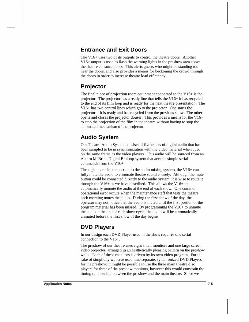
Application Notes 7-5
Entrance and Exit Doors
The V16+ uses two of its outputs to control the theatre doors. Another
V16+ output is used to flash the warning lights in the preshow area above
the theatre entrance doors. This alerts guests who might be standing too
near the doors, and also provides a means for beckoning the crowd through
the doors in order to increase theatre load efficiency.
Projector
The final piece of projection room equipment connected to the V16+ is the
projector. The projector has a ready line that tells the V16+ it has recycled
to the end of its film loop and is ready for the next theatre presentation. The
V16+ has two control lines which go to the projector. One starts the
projector if it is ready and has recycled from the previous show. The other
opens and closes the projector douser. This provides a means for the V16+
to stop the projection of the film in the theatre without having to stop the
automated mechanism of the projector.
Audio System
Our Theatre Audio System consists of five tracks of digital audio that has
been sampled to be in synchronization with the video material when cued
on the same frame as the video players. This audio will be sourced from an
Alcorn McBride Digital Binloop system that accepts simple serial
commands from the V16+.
Through a parallel connection to the audio mixing system, the V16+ can
fully mute the audio to eliminate theatre sound entirely. Although the mute
button could be connected directly to the audio system, it is wise to route it
through the V16+ as we have described. This allows the V16+ to
automatically unmute the audio at the end of each show. One common
operational error occurs when the maintenance staff that tests the theatre
each morning mutes the audio. During the first show of the day, the
operator may not notice that the audio is muted until the first portion of the
program material has been missed. By programming the V16+ to unmute
the audio at the end of each show cycle, the audio will be automatically
unmuted before the first show of the day begins.
DVD Players
In our design each DVD Player used in the show requires one serial
connection to the V16+.
The preshow of our theatre uses eight small monitors and one large screen
video projector, arranged in an aesthetically pleasing pattern on the preshow
walls. Each of these monitors is driven by its own video program. For the
sake of simplicity we have used nine separate, synchronized DVD Players
for the preshow; it might be possible to use the three main theatre disc
players for three of the preshow monitors, however this would constrain the
timing relationship between the preshow and the main theatre. Since we
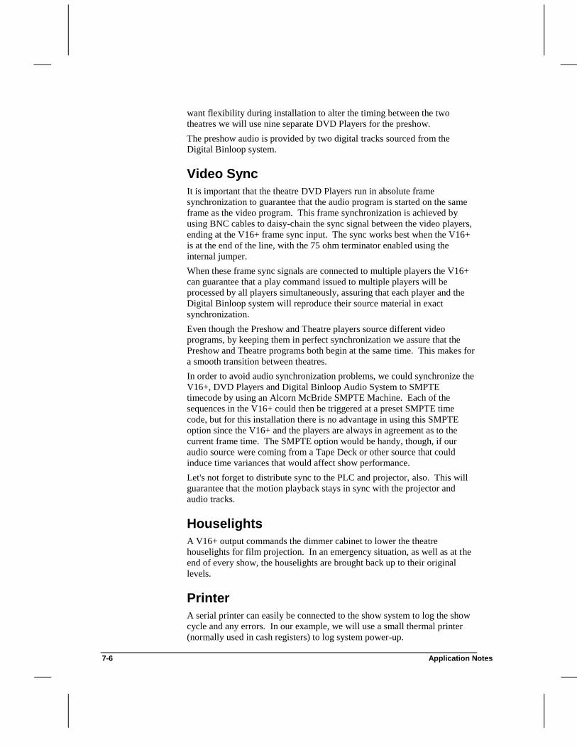
7-6 Application Notes
want flexibility during installation to alter the timing between the two
theatres we will use nine separate DVD Players for the preshow.
The preshow audio is provided by two digital tracks sourced from the
Digital Binloop system.
Video Sync
It is important that the theatre DVD Players run in absolute frame
synchronization to guarantee that the audio program is started on the same
frame as the video program. This frame synchronization is achieved by
using BNC cables to daisy-chain the sync signal between the video players,
ending at the V16+ frame sync input. The sync works best when the V16+
is at the end of the line, with the 75 ohm terminator enabled using the
internal jumper.
When these frame sync signals are connected to multiple players the V16+
can guarantee that a play command issued to multiple players will be
processed by all players simultaneously, assuring that each player and the
Digital Binloop system will reproduce their source material in exact
synchronization.
Even though the Preshow and Theatre players source different video
programs, by keeping them in perfect synchronization we assure that the
Preshow and Theatre programs both begin at the same time. This makes for
a smooth transition between theatres.
In order to avoid audio synchronization problems, we could synchronize the
V16+, DVD Players and Digital Binloop Audio System to SMPTE
timecode by using an Alcorn McBride SMPTE Machine. Each of the
sequences in the V16+ could then be triggered at a preset SMPTE time
code, but for this installation there is no advantage in using this SMPTE
option since the V16+ and the players are always in agreement as to the
current frame time. The SMPTE option would be handy, though, if our
audio source were coming from a Tape Deck or other source that could
induce time variances that would affect show performance.
Let's not forget to distribute sync to the PLC and projector, also. This will
guarantee that the motion playback stays in sync with the projector and
audio tracks.
Houselights
A V16+ output commands the dimmer cabinet to lower the theatre
houselights for film projection. In an emergency situation, as well as at the
end of every show, the houselights are brought back up to their original
levels.
Printer
A serial printer can easily be connected to the show system to log the show
cycle and any errors. In our example, we will use a small thermal printer
(normally used in cash registers) to log system power-up.

Application Notes 7-7
More Outputs?
To keep our sequence examples simple, we have used only eight outputs of
the sixteen available on the V16+. Many other discrete output possibilities
can be added. For example, you could add independent show run, pause,
and stop lights, cue lights for both the Theatre and Preshow OCCs, and
control of special effects within the theatre. Also, the V16+ could control
the OCC microphone mix to the audio equipment. To utilize more than
sixteen inputs or outputs, additional IO64 Discrete I/O Expanders must be
connected to the V16+.
Configuring the V16+
Now that we have designed the architecture of our show we need to
describe it to the V16+. This is done with screens that, to a large extent,
mimic the decisions that we have already made.
We begin from the main menu of the WinScript programming software by
selecting the File | New option and choosing V16+ from the product list.
Next, let’s give our show a name…how about "MYSHOW"?
Let’s continue by selecting the Configuration | Unit… menu item. This
Dialog Box allows us to describe the environment that the script will be
executing in. Information requested here includes the Unit Type (V16+),
Unit Address, and frame rate. The selection of frame rate affects the frame
numbers used while programming our sequences, so this selection should be
made before we do any sequence programming. The V16+ clock can be
sourced from the processor's internal oscillator or from an external clock at
any rate up to 3000Hz. We will be using external frame sync from one of
the DVD Players, so set the Clock Source to External.

7-8 Application Notes
After closing this menu, we choose Resources | Inputs… . This is a
simple menu which lists all of the inputs to the V16+ and allows us to give
them English names which will be used throughout our sequences. Using
the input hardware descriptions we arrived at previously, we assign our
names.
Next we close this screen and move on to Resources | Outputs… . In a
similar fashion we give the outputs names that we wish to use throughout
our sequences.

Application Notes 7-9
Next we choose Resources | Flags…. Flags 1-12 are used as “Ready
Flags” to be turned “ON” when the corresponding DVD Players is “Ready”
to start the show. The exact information to enter into the fields is given in
Figure 11.

7-10 Application Notes
Now we move on to Resources | Ports… . This is where we configure the
V16+ for the number and type of DVD Player to which it is connected. For
each player in use we select a baud rate, data format (parity, length in bits, and
number of stop bits) and a manufacturer's protocol. This protocol can be
specific to Sony or Pioneer disc players, or can be a custom protocol designed
by the user. The Programmer Port is always port 0, and its type is set to Alcorn
9 Bit Control. In our show we will connect the V16+ to the 12 Pioneer disc
players described previously, plus the Digital Binloop Audio System, a serial
printer for data logging, and a Ride Control PLC. This uses 15 of the 16 serial
ports of the V16+.

Application Notes 7-11
Next, we choose the Resources | LCD Strings… menu and create the
display messages that will be seen on the V16+ LCD Display before, during,
and after each show.
Finally, we go to the Resources | Data Strings… menu and create some
serial strings for use in our sequences. This allows us to construct
specialized serial messages that are not constructed by the script compiler.
Do not enter search and play commands here. They are created
automatically. This is the place, however, to define custom messages to be
sent to the printer and RCC.
In a more complex show we could design a custom serial protocol for the
RCC into a Protocol File, but since we will only be sending it one “start”
message, we will keep the message in the Data Strings configuration for
simplicity. In a real show situation, the messaging might be more complex,
so please refer to your specific equipment manuals for information on serial
protocols.

7-12 Application Notes
Now our V16+ is fully configured for its operating environment. The next
step is to create and add events to the sequences of MYSHOW.
Configuring Sequences
We now will edit and configure our sequences by working with the Sequences of MYSHOW window. The V16+ supports up to 256
sequences. Each sequence may be up to 32,767 events long (although our
V16+ can only hold around 8,192 total events since it supports a maximum
of 64KB of show memory), and all sequences execute independently and
simultaneously. Each sequence is started, paused, stopped and reset by its
own unique set of conditions and can interact with other sequences as well.
The logical place to begin our sequence programming is with our auto-
executed sequence, the one that is also initiated by pressing the first button
on the V16+ front panel. This is our show startup function and will bring
all of the equipment in the attraction to a known starting state whenever the
V16+ is first powered up or this first button is pushed.
Each sequence that we write must have its own setup properly filled in, in
order to behave in the way that we expect. Double-click on the name of the
Default sequence in the list and change the sequence name to “Startup”.
For each sequence we can assign dedicated start, stop, pause and reset
functions. These are normally attached to the front panel buttons on the
V16+. In the case of our Startup sequence we have no requirement for a
stop, pause or reset button. We do, however, want to attach the V16+'s first
button to start this sequence by setting the Start Trigger of Startup to
FrontPanelStart. We also want this sequence to be Autostart Enabled so
that it will start immediately at powerup.
Similarly, the sequences Startshow and EStop should be assigned start
triggers of OCCStart and OCCStop, respectively. The rest of our
sequences will be started and reset by other sequences, so they should not
be assigned any triggers.
Programming Sequences
Up to this point we have configured the V16+ environment and given
English names to its input, output and serial ports. We have also defined
some general purpose strings and given them English names. All of this

Application Notes 7-13
configuration information now becomes a tool which we can use to create
the sequences that will make our theatre run.
The sequence entry we are about to perform will result in a completed V16+
script consisting of a few sequences. Obviously with nine unused inputs,
eight unused outputs and 212 unused sequences there is plenty more we can
make this V16+ do. But these sequences will give you an idea of the
V16+'s capabilities and form a rudimentary but complete theatre control
system.
One of the most powerful aspects of the V16+ is the inter-relationship that
sequences can have amongst themselves. Several of our example sequences
will illustrate the flexibility this gives us.
The first sequence for which we will enter events is our Startup sequence.
The function of Startup is to initialize outputs to known states. As you
recall, this sequence is executed automatically when the V16+ and other
equipment is first powered up. It is also executed whenever the first push
button on the V16+ front panel is pressed.
The very first activity in our startup sequence must be to reset other
important sequences. Since many of our sequences operate the same
outputs, allowing some other sequences to run during Startup could cause
interesting and unpredictable interactions. When first powering up the
V16+, of course, the other sequences will not be running, but they may be if
the start button is pushed later during the day.
Startup continues by initializing all of the V16+ outputs to a known state.
When the V16+ is first powered up all of its outputs are initialized to off;
however, since the Startup sequence can be executed at any time, the state
of the outputs is unknown. We therefore initialize all of them. Do this
using the Off and On events in the Event column and the English names of
the outputs in the Data1 column. Using these commands, we turn off the
operator console cue light, close the exit doors, turn off the projector start
and douser lines and turn off the audio mute line.
We also want to set the entrance doors to their normal rollover state, which
in our case is going to be open. Before we do this we should blink the
warning lights for 5 seconds to alert anyone near the doors that they are
going to move. Do this using the Blink event, putting the warning light
name in the Data1 column and a one second blink rate into the Data2
column.

7-14 Application Notes
Now that the rest of the theatre is ready, we start the Recycle sequence
which will get all 12 DVD Players ready. Since we do not know how long
it will be until the first performance, it is necessary to search the DVD
Players as fast as possible. To do this, we start 12 independent search
sequences (SearchTheatre1, SearchTheatre2, SearchTheatre3,
SearchPreshow1, etc.) that turn the corresponding flag “ON” when the
player has been searched. Also, to insure that all outputs will be “OFF”
when the Search sequences begin, we simply turn them all “OFF” before we
start Search sequences 1-12.
If all twelve SelectClip events were put in the same sequence, the time
that it takes for each player to spin-up will accumulate. Even though they
would be scripted to occur on the same frame, the final SelectClip event
could be over 4 minutes late!

Application Notes 7-15
Recycle is used at the end of each show to bring the DVD Players to the
beginning of the file in preparation for show playback. Make sure that there
are no triggers assigned to this sequence. It cannot be activated by any
switch closure. It is only activated by other sequences. This sequence does
not have the ability to be restarted and will not Autostart either. Essentially
the entire configuration has been set to an inactive state.
Just before Recycle ends we start another sequence: DVD PlayerSearched?.
DVD PlayerSearched? constantly checks the status of each DVD Player, so
it should be Loop Enabled. If even one of the players isn’t powered or is not
responding, the show cannot begin, but eventually the SelectClip
commands inside the Search sequences will time-out and the show will
commence, even though a DVD Player may not be spun-up. When all
DVD Players are searched. the ShowReadyFlag is set.

7-16 Application Notes
Our next sequence is StartShow. StartShow is actuated by the start button
on the theatre operator's console. Our theatre presentation is designed so
that it can automatically loop all day long after the first show is manually
started. To run the first show of the day the operator presses the OCC start
button and StartShow begins execution. Configure StartShow to have the
OCCStart input as its start trigger and don’t forget to check the Loop
Enable checkbox to assure that we continually check for the projector
ready-line.
StartShow uses the LCD display command to inform us that it is waiting for
the projector ready line. Next it checks to see if the projector ready line is
active. If it is not, it jumps over the next line to the Nop at the end of the
sequence, labeled loop. As soon as the sequence reaches the end, it begins
again at the beginning. When the projector is ready, StartShow confirms
that the DVD Players have been searched to the correct frame, starts the
main show sequence, Showtime, and resets itself so that it won’t interfere
with other sequences.

Application Notes 7-17
Showtime is the main timekeeping sequence for running the theatre show.
Showtime's 0 starting frame corresponds to the first frame played back from
all of the DVD Players. We define it this way to make it easier to program
the sequence of theatre events: all of the time offsets throughout the
sequence are relative to the show frame being played back. (If events need
to occur after StartShow and before the DVD Players play, these events
should be placed in another sequence started by StartShow. At its
completion that new sequence should start Showtime.)
Showtime immediately issues a play command to all of the DVD Players.
Again we do this by starting multiple parallel sequences to assure that the
commands are all processed in parallel and all the players start on the same
frame. By doing this we have guaranteed that the V16+ will send the serial
commands to all players simultaneously.
Simultaneously with a play command to all of the DVD Players, Showtime
sends a start message to the Digital Binloop system. Next, we send a start
pulse message to the projector. Then, we send a serial message to the RCC
telling it to start its motion control playback.

7-18 Application Notes
Now that we have completed the time critical activities that occur at frame 0
we can perform some lower priority functions. We display "Show
Running" on the LCD and command the house lights, entrance doors, audio
mute, and cue light off. Five seconds after the projector started we open the
douser.
The show is now running. Our imaginary show ends at 2 minutes, 45
seconds. Twenty seconds prior to that we pulse the operator console cue
light for 3 seconds to cue the operators to prepare for their spiels. Now the
show is over. We close the douser, bring up the house lights and open the
exit doors. We also start the Recycle, previously described, to bring the
DVD Players back to their starting positions. Notice that Recycle is
performing this activity while Showtime continues to run.
Now we blink the warning lights for the entrance doors. The preshow
operator provides a fifteen second speil and then we open the entrance doors
and turn off the warning lights. After an additional 25 seconds we close the
exit doors.
Next we check the state of the operator console pause switch. (To simplify
things, we are using a maintained switch. A momentary would work just as
well, but we would need an extra sequence and a flag to hold its state.). If
the switch is in the pause position, then we should not Recycle the show
automatically. We instead jump to the End label. If the switch is not
paused, then we can re-initiate the entire show cycle by starting StartShow.
If we are in pause, we display a status message on the LCD display to that
effect.
The final sequence, EStop, is responsible for handling the operator console
stop button. When pressed it closes the douser, brings up the houselights
and stops the other sequences.
Summary
As you can see, the V16+ provides a wealth of Show Control power and
versatility to even the most complex of shows, providing exact timing and
control over all show systems.

Application Notes 7-19
Digital Video Machine Control The Alcorn McBride Digital Video Machine is the most robust video
playback unit available today; providing near-instantaneous access to up to
9,999 individual video clips.
In this example, we have established a new hotel, the Alcorn Inn, and are
seeking ways to advertise our new hotel to current or would-be tourists. Our
marketing department comes up with an idea for an interactive kiosk that
provides prospective customers with a rich multimedia presentation touting
the great benefits of staying at the Alcorn Inn. Energized by the marketing
pep-talk, we quickly decide to combine an Alcorn McBride V2+ and DVM
to provide both control and audio/video sourcing for our kiosk.
You can follow along with this application note in WinScript by opening
DVM.AMW (located in the WinScript\Scripts\Examples\ directory).
Note This application note assumes that the reader possesses rudimentary
scripting skills. New users should take the WinScript Tutorial in Chapter 3
before continuing.
How Our Kiosk Works
At power-up, our kiosk will run an "Attract Loop". This video sequence will
be a succession of still-images taken at the Alcorn Inn and will loop at the
end (the first and last still images are the same, providing a seamless
transition back to the beginning).
When a guest steps up to the kiosk, the motion sensor is tripped and a short
"welcome" video message is played. The guest is then given the choice to
view one of four clips: Great Rooms, Great Food, Great Rates, and a
Special Offer. Great Rooms, Great Food, and Great Rates are located on the
Internal drive of the DVM, and Special Offer is located on the Removable
drive (this allows us to change our special offer at any time without having
to copy the clip to the Internal drive). If the guest does not select a clip
within ten seconds, it is assumed that they have walked away and the kiosk
returns to the Attract Loop.
If the guest chooses a clip by pressing one of the buttons, the clip is played
and then the Welcome clip is played again. Once the guest views all of the
desired clips and walks away (hopefully to the nearest phone to reserve a
week at the Alcorn Inn), the kiosk will return to the Attract Loop.
Here is a listing of all the clips and playlists on our DVM:
Removable Drive Internal Drive
Clip Name File Name Clip Name File Name
Special Offer VID00001.MPG Attract Loop Playlist PLY00000.LST
Great Rooms Clip VID00001.MPG
Great Food Clip VID00002.MPG

7-20 Application Notes
Great Rates Clip VID00003.MPG
Welcome Clip VID00004.MPG
Attract Loop Clip VID00005.MPG
Creating The Attract Loop Playlist
We want our kiosk to start the Attract Loop as soon as possible after
powerup, so we will use the Attract Loop Playlist located on the Internal
drive to play and loop the Attract Loop clip as soon as the DVM has
powered up. The Playlist is created as follows:
I ;Our Attract Loop is interruptible
L5 ;Loop Attract Loop Clip (VID00005.MPG)
Programming the V2+
First, we configure Port 1 of the V2+ for the Alcorn McBride Digital Video
Machine:
Next, we assign our contact closure inputs: Input 9 of the V2+ is connected
to the motion sensor, Inputs 10-13 are connected to the four external
pushbuttons, and Input 14 is connected to the Playing output of the DVM:

Application Notes 7-21
To prevent the guest from being able to interrupt a clip while it is playing,
we will use two flags to keep track of where we are in the show. This will
allow our sequences to decide whether or not they should accept input from
the guest. PlayingClipFlag will be turned on when one of our four
informational clips is playing, while PlayingWelcomeFlag will be turned
on when the “Welcome” clip is playing.
Next, we want to create the sequences that provide the interactivity of our
kiosk and tightly control the flow of the show. The sequences we will use
are listed in the figure below:

7-22 Application Notes
Our first sequence will be the Attract Loop sequence. Although this
sequence won’t be used at powerup, it will be called on to play the Attract
Loop after a guest has stepped away from the kiosk. AttractLoop selects the
Internal drive of the DVM with the SelectDrive event and then commands
the DVM to continuously play and loop the Attract Loop clip.
Our next sequence is a housekeeping sequence that has become
commonplace in many scripts. This sequence, ResetFlags,
indescriminately resets all of the flags that we are using in this script. We
will use this sequence to return the flags to a known state at certain points in
the show.

Application Notes 7-23
MotionSensor triggers the sequence Welcome. This sequence resets the
flags using ResetFlags to ensure that the show is in a known state, turns
on PlayingWelcomeFlag to alert the other sequences that the Welcome
clip is currently playing, and then plays the Welcome clip.
When PlayInput (the Playing output of the DVM) turns off, we know that
one of the clips has just finished playing - but which one? Using the two
flags we created earlier (PlayingWelcomeFlag and PlayingClipFlag),
we can create a sequence that is triggered when PlayInput turns off. We
can then decide whether it should wait for the guest to push a button (after
Welcome has finished), or immediately play the Welcome clip (after an
informational clip has played).
Our sequence, ClipFinished, first checks the state of PlayingClipFlag.
If it is on, the sequence knows that the DVM has just finished playing one
of the four informational clips. It turns off PlayingClipFlag and starts
Welcome (which plays the Welcome clip again). If PlayingClipFlag is
off, then the sequence checks the state of PlayingWelcomeFlag. If
PlayingWelcomeFlag is on, the sequence knows that the DVM has just
finished playing the Welcome clip and that it should wait for the guest to
push a button. It turns off the flag and starts our "waiting" sequence,
WaitingForSelection. We are only interested in the status of the four
informational clips and the Welcome clip during the show, so if both flags
are off, we do nothing.

7-24 Application Notes
WaitingForSelection waits ten seconds after the Welcome clip finishes
and then restarts the Attract Loop, assuming that the guest has walked
away. If the guest presses a button during the ten-second interval, the
sequence that corresponds with that button will reset
WaitingForSelection so that it does not restart the Attract Loop.
We provide four separate sequences (triggered individually by a
corresponding pushbutton) to play our informational clips: GreatRooms,
GreatRates, GreatFood, and SpecialOffer. These sequences check the
status of both flags. If either flag is on, the sequence knows that another clip
is playing and it should not interrupt it, so it does nothing. This forces the
guest to watch a clip in its entirety before choosing another.

Application Notes 7-25
Each sequence resets WaitingForSelection to prevent it from starting the
Attract Loop ten seconds later. After the informational clip has finished
playing, ClipFinished starts the Welcome clip again. When the guest has
viewed all the desired clips and walks away, the kiosk automatically times
out, starts the Attract Loop and waits for the next guest.
Summary
As you can see, controlling video playback from a Digital Video Machine is
extremely straightforward. Near-instantaneous access times eliminate the
need for independent Spinup, Spindown, or Search sequences. Also, the
Playing output allows us to make our script clip-independent, so we can
change the lengths or content of our clips at any time without reworking the
script. An V2+ / DVM combination is ideal for many applications.

7-26 Application Notes

Application Notes 7-27
Using Cue List in a Live Show
Many live shows use SMPTE timecode to keep the audio, video, lighting and show control in
sync. In some of these shows, the programmer has the luxury of a timecode list. Typically this
list is dictated by the audio program and indicates the timecode locations at which certain events
must happen. When this luxury exists, programming your show with timecode is as simple as
entering in timecode triggers in WinScript in the appropriate sequences, as discussed earlier.
When you do not have the benefit of a timecode listing, you can use Cue List to attach timecode
triggers to your sequences in real time. By running the show with timecode and cueing the show
in real time, you can place your sequences at the exact time that you desire while watching the
entire show with all show elements.
To illustrate the use of Cue List, here is a sample application: a live show on a cruise ship. This
show involves an audio playback source and a lighting console that both track timecode.
Additionally, there are video sources and a router that must function within the show. For this
application, we will use a SMPTE Machine and a V16+.
In live shows, such as this one, the number of times the show is run with all elements is very
small. This is because it is very difficult to run the show multiple times with the cast and the cast
is often critical in adjusting the timing of show control and lighting elements. Therefore, it is
important to use each valuable run of the show as much as possible. In this case, we would like to
trigger as many sequences as possible and fine-tune the show with each successive run.
In this particular instance, we pre-program the sequences to decide which video clip should play at
different phases in the show and what video source should be routed at various times. Once all of
the programming has been done, we can run Cue List. The first step is to arrange the Sequences in
the rough order that they should occur in the show under the “Cues On” window. While it is
possible to re-arrange these Cues while we are running the show by dragging them up and down in
the list, it is easier to do this now while you are not distracted by the show running. Once you are
ready to go, you can set the Start Time, Reset to the Start Time, and Start the Timer. If you are
running a show in which the SMPTE Machine is not the SMPTE generator, you should push the
Start Timer button when the timecode source starts. As the director calls for the sequences to be

7-28 Application Notes
run, it is easy to move the sequences from the “Cues On” window to the “SMPTE Triggers”
window.
After all of the Cues have been placed, the Cue Times can be adjusted by moving the questionable
sequences back to the “Cues On” window and re-running the show. Another option is to modify
the trigger times by right-clicking on the sequence, selecting the SMPTE Trigger, and modifying it
accordingly.
If you would like to program your show off-line, while relaxing on the pool deck, it is easy to run
Cue List with a tape of the audio source (or a video tape of the show). Simply run the source and
start the timer. At the appropriate locations, move the sequences from the “Cues On” window to
the “SMPTE Triggers” window. After this has been completed, you can return to the theatre,
download your script and fine-tune the show on the next run-through. This also works if you are
programming the show in your cabin if it is raining on the pool deck.
With Cue List, it is easy to adjust show control timing while all the other show components are
adjusted and keep the director happy.

Application Notes 7-29
Controlling Automatic Doors There are many applications where an Alcorn McBride Show Controller
can perform non-safety-related duties normally delegated to a PLC. One
application that immediately comes to mind is automatic theatre doors.
These doors open when the main show is loading/unloading (as in the Large
Theatre Control example). The Show Controller should automatically
open/close the doors as dictated in the script except when overridden by an
operator control switch.
This simple example utilizes a three-position maintained switch to provide a
Show Controller with two inputs: Open and Close. The center position is
Auto, and can be deduced by the absence of both Open and Close inputs.
When the switch is in the Open position, the Show Controller should keep
the doors open, regardless of what the show is doing at the moment. The
same is true with the Close position; the doors should remain closed
regardless of the status of the show. In the Auto position, the Show
Controller can dynamically open and close the doors at the appropriate
time. A flag will provide automated control of the doors from within any of
the other sequences: the sequence will turn the flag on to open the doors
and off to close the doors. If a set of doors is in Auto mode, our looping
sequence should open/close them based on the state of the flag. If the doors
are in Open or Close mode, the other sequences may still turn on and off
the flag, but the doors will not be affected.
We will perform this function by using one Loop Enabled sequence that
continuously checks the inputs and opens/closes the doors if necessary.
The figure below shows the events of our sequence, OpenCloseDoors.
This sequence loops every 10 frames and update the state of the doors based
upon the switch inputs (DoorOpenInput and DoorCloseInput) and the script
open/close flag (DoorFlag). The sequence first checks if either input is on.
If the operator has moved the switch to the Open position, the doors should
be opened. Similarly, if the operator has moved the switch to the Close
position, the doors are automatically closed without regard to DoorFlag.
Finally, if the doors are in the Auto position, the status of DoorFlag is
checked. If DoorFlag is "on" the doors are opened, and vice versa.

7-30 Application Notes
Summary
Using flags as "permission" outputs allows a separate sequence to monitor
the status of operator controls, check the flag, and perform the desired
action ("grant permission"), if possible. As you can see, we have saved
considerable Ladder Logic programming (and perhaps an entire PLC) by
utilizing one sequence, one flag, and two inputs to control our automatic
doors.

V16+ Hardware Reference 8-1
V16+
V16+ Hardware Reference
The V16+ is the latest version of our original, and still most powerful, Show
Controller. It is ideally suited for the control of video walls, large theaters, and
multiple kiosks or interactive games. It provides more serial ports than any of
our other controllers, and offers the largest possible show memory capacity.

8-2 V16+ Hardware Reference
Specifications
Size XE "Size" Standard 2U rack mount (3.5” x 19” x 6.5”), 10 lbs
Power: 100 to 250 VAC, 50 to 60 Hz, 25 watts maximum.
UL listed Class 2 power adapter
Environment: 0 to 35 C (32 to 100 F)
0 to 90% relative humidity, non-condensing
Front Panel: 2x40 LCD Display
Power LED
Acknowledge (ACK) LED
Error LED
16 Serial Activity LEDs
16 Input Status LEDs
16 Output Status LEDs
16 Pushbuttons
Rear Panel: Programming Port DB-9M
16 Serial Ports DB-9M
MIDI Input 5-pin DIN Female
MIDI Output 5-pin DIN Female
Discrete Inputs DB-37M
Discrete Outputs DB-37F
NTSC or PAL Sync Input BNC
Power 5-pin DIN Female
Serial Ports: (16) RS-232C
300 baud - 38.4 Kbaud
7, 8, or 9 Data Bits
1 or 2 Stop Bits
All parity types
4 ports can be configured as RS-485/422
1 port can be configured as MIDI
Opto Inputs: (16) 24 VDC, 20 mA maximum
Reconfigurable for voltages down to 5 VDC or for pure
contact-closure operation. Trigger latency < 1 frame.
Relay Outputs: (16) Contact Closures limited internally to 900 mA with
self-restoring polymer fuses.
Show Memory: 32 Kbyte EEPROM, expandable to 64 Kbytes.
Nonvolatile, robust memory retains show data permanently
with no battery backup required.

V16+ Hardware Reference 8-3
V16+
Serial Ports The V16+ provides 16 serial ports which may be configured as shown below:
Port Type Description Connector
0 RS-232 Programmer Port DB9M
1 RS-232* / RS-485 Port 1 DB9M
2 RS-232* / RS-485 Port 2 DB9M
3 RS-232* / RS-485 Port 3 DB9M
4 RS-232* / RS-485 Port 4 DB9M
5 RS-232 Port 5 DB9M
6 RS-232 Port 6 DB9M
7 RS-232 Port 7 DB9M
8 RS-232 Port 8 DB9M
9 RS-232 Port 9 DB9M
10 RS-232 Port 10 DB9M
11 RS-232 Port 11 DB9M
12 RS-232 Port 12 DB9M
13 RS-232 Port 13 DB9M
14 RS-232 Port 14 DB9M
15 RS-232 Port 15 DB9M
16 RS-232* / MIDI Port 16 DB9M / (2) 5 Pin DIN F
Table 1 – V16+ Ports located on the Rear Panel. *Factory Default Setting
Note RS-485 is used throughout this manual to denote ports that may be used
for both RS-422 and RS-485 communication.
Programmer Port
The Programmer Port is an RS-232C serial port used to program the V16+.
Pin Connection
2 RS-232 TXD
3 RS-232 RXD
5 GND
8 +12V Pull Up
Table 2 – Programmer port connections.

8-4 V16+ Hardware Reference
Ports 1-4: RS-232 or RS-485
Ports 1-4 are factory configured as RS-232C, but can be reconfigured as a group
as RS-485. The V16+ includes internal 220 Ohm termination for RS-485, so an
external terminator for the unit is not necessary. To configure ports 1-4 for RS-
485/422 operation, the 1488 and 1499 RS-232 Driver and Receiver chips must
be removed and 75174 and 75175 Driver and Receiver chips installed. (See the
Appendices for manufacturer’s part numbers.)
Pin RS-232 Connection RS-485 Connection
2 RS-232 RXD RS-485 RX+
3 RS-232 TXD RS-485 TX+
4 +12V Pull up +12V Pull up
5 GND GND
6 N/C RS-485 RX-
7 +12V Pull up +12V Pull up
9 N/C RS-485 TX-
Table 3 – Ports 1-4 connections for RS-232 and RS-485 operation.
Configuring Ports 1-4 as RS-485
1. Remove the 1489 chip from U49 and the 1488 chip from U54.
2. Install a 75174 chip in U46 and a 75175 RS-485 chip in U47.
3. Install a 10K R-Pack in RP12 and a 220 Ohm SIP in RP13.
Configuring Ports 1-4 as RS-232
1. Remove the 75174 chip from U46 and the 75175 chip from U47.
2. Install a 1489 chip in U49 and a 1488 chip in U54.
3. Remove the resistor packs located in RP12 and RP13.
Ports 5-15: RS-232
Ports 5-15 are permanently configured as RS-232C serial ports.
Pin Connection
2 RS-232 RXD
3 RS-232 TXD
4 +12V Pull Up
5 GND
7 +12V Pull Up
Table 4 – Ports 1-15 connections for RS-232 operation.

V16+ Hardware Reference 8-5
V16+
Port 16: RS-232 or MIDI
Port 16 is factory configured as an RS-232C serial port, but can be reconfigured
as a MIDI port. When reconfigured, MIDI Input is received by the MIDI IN
port, and MIDI Output is sent out the MIDI OUT port.
Configuring Port 16 as MIDI
1. Set jumpers W1 and W2 to the “MIDI” position.
2. Configure Port 16 in WinScript as “MIDI”.
3. Configure the baud rate of Port 16 in WinScript as 31250 baud.
MIDI IN
Pin Connection
4 MIDI RX+
5 MIDI RX-
Table 5 – MIDI IN connections.
MIDI OUT
Pin Connection
2 GND
4 MIDI TX+
5 MIDI TX-
Table 6 – MIDI OUT connections.
Configuring Port 16 as RS-232
1. Set jumpers W1 and W2 to the “RS-232” position.
LCD Display The V16+ includes a standard 2x40 (80 character) Backlit LCD Display. An
internal potentiometer is used to adjust the contrast (viewing angle) of the LCD.
Adjusting the LCD contrast
1. To make the display lighter, turn “CONTRAST” control R8 clockwise.
2. To make the display darker, turn R8 counter-clockwise.

8-6 V16+ Hardware Reference
Digital Inputs
Input Connector
The V16+ includes 16 Opto-isolated inputs that can control the show operation.
These inputs can be activated by pressing the corresponding front panel button
(button 1 corresponds with input 1, etc.) or by electrically activating the input
through the Parallel Inputs connector located on the rear panel.
Pin Connection Pin Connection
1 Input 1 20 Input 1 Return
2 Input 2 21 Input 2 Return
3 Input 3 22 Input 3 Return
4 Input 4 23 Input 4 Return
5 Input 5 24 Input 5 Return
6 Input 6 25 Input 6 Return
7 Input 7 26 Input 7 Return
8 Input 8 27 Input 8 Return
9 Input 9 28 Input 9 Return
10 Input 10 29 Input 10 Return
11 Input 11 30 Input 11 Return
12 Input 12 31 Input 12 Return
13 Input 13 32 Input 13 Return
14 Input 14 33 Input 14 Return
15 Input 15 34 Input 15 Return
16 Input 16 35 Input 16 Return
17 N/C 36 N/C
18 N/C 37 N/C
19 N/C
Table 7 – Parallel Input connections.
Two forms of input signal can be applied to the Parallel Inputs connector:
Voltage Inputs, and Contact Closures. When a specific input on the V16+ is
configured for Voltage Inputs, power for the connection is provided by an
external source (in-rack power supply etc.), but when the input is configured as
a Contact Closure, power is taken internally from the V16+.

V16+ Hardware Reference 8-7
V16+
Voltage Inputs vs. Contact Closures
There are many advantages to using Voltage Inputs over Contact Closures.
First, a Contact Closure can only be located a short distance from the V16+.
Second, Contact Closures use the V16+’s own power supply, so external wiring
errors can damage the entire unit.
Figure 1 – Contact Closure Schematic.
Figure 2 – Voltage Input Schematic.
Configuration Maximum Distance
Contact Closures 10ft
Voltage Inputs Limited only by wire gauge
Table 8 – Voltage Inputs are advantageous for many reasons, including the distance at
which they are operational.

8-8 V16+ Hardware Reference
Input Configuration
Two sets of DIP switches on the main V16+ circuit board select the type of each
input. Switches SW17 & SW18 configure Inputs 1-8, while switches SW19 &
SW20 configure Inputs 9-16.
Figure 3 – Inputs 1-4 and 9-12 are Voltage Inputs. Inputs 5-9 and 13-16 are Contact
Closures.
Configuring Inputs as Voltage Inputs
1. Install the appropriate Resistor Pack in RP6 and RP8 (see table 9).
2. For each Input that is to be a voltage input, switch both corresponding DIP
switches (one position on SW17 & SW18 for Inputs 1-8 or one position on
SW19 & SW20 for inputs 9-16) to the “OFF” (or down) position. In the
Figure, Inputs 1-4 and 9-12 have been configured as voltage inputs.
Voltage Level Used Resistor Pack Value
5V 180 Ohm
12V 470 Ohm
24V 1.5K Ohm*
Table 9 – Recommended Resistor Pack values for Voltage Inputs.
* Factory Default Setting
Configuring Inputs as Contact Closures
1. For each Input that is to be a contact closure, switch both corresponding
DIP switches (one position on SW17 & SW18 for Inputs 1-8 or one position
on SW19 & SW20 for inputs 9-16) to the “ON” (or up) position. In the
Figure, Inputs 5-8 and 13-16 have been configured as contact closures.

V16+ Hardware Reference 8-9
V16+
Input Wiring
Connecting a Voltage Input
1. Verify that the appropriate Resistor Pack is installed in sockets RP6 and
RP8 (see Table 9).
2. Locate DIP switches SW17, SW18, SW19, and SW20.
3. Verify that the appropriate switches are configured for Voltage Input.
4. Using a Female DB37 connector, attach the appropriate wire from the Input
signal pin (pin 1 for Input1, pin 2 for Input2, etc.) to the positive terminal
of the external power supply.
5. Connect the negative terminal of the external power supply to one of the
terminals of the contact closure or push button.
6. Connect the appropriate Input Return pin to the other terminal of the contact
closure (pin 20 for Input1, Pin 21 for Input2, etc.)
Figure 4 – Sample connection for a Voltage Input to Input1 of the Parallel Inputs
connector. The terminal blocks are used for power bussing and modularization of the
input signals.

8-10 V16+ Hardware Reference
Connecting a Contact Closure
1. Locate DIP switches SW17, SW18, SW19, and SW20.
2. Verify that the appropriate switches are configured for Contact Closures.
3. Using a Female DB37, attach the appropriate wire from the Input signal pin
(pin 1 for Input1, pin 2 for Input2, etc.) to one of the terminals of the
external contact.
4. Connect the appropriate Input Return pin to the other terminal of the
external contact (pin 20 for Input1, Pin 21 for Input2, etc.)
Figure 5 – Sample connection for a Contact Closure Input to Input1 of the Parallel
Inputs connector.
Disabling Front Panel Buttons
The V16 provides 16 front panel buttons which duplicate the function of the 16
external inputs. This is convenient for test purposes, but it is often desirable to
prevent the unintentional activation of these signals by the front panel. Any
signals that should not be allowed front panel control should be assigned to
inputs 9 through 16. These front panel switches may be individually disabled
using DIP switch SW21.
Disabling front panel buttons 9-16
1. For each button to be disabled, move the corresponding switch of SW21 to
the “OFF” position (Switch 1 for Input9, Switch 2 for Input10, etc.)

V16+ Hardware Reference 8-11
V16+
Digital Outputs
Output Connector
In addition to discrete input, the V16+ provides 16 Dry-Contact Relay Outputs
for discrete control.
Note The Relay Outputs are fused at 900mA using self-restoring polymer
fuses. If an overload occurs, the fuse will open until the problem is corrected;
then heal itself.
Pin Connection Pin Connection
1 Output 1 20 Output 1 Return
2 Output 2 21 Output 2 Return
3 Output 3 22 Output 3 Return
4 Output 4 23 Output 4 Return
5 Output 5 24 Output 5 Return
6 Output 6 25 Output 6 Return
7 Output 7 26 Output 7 Return
8 Output 8 27 Output 8 Return
9 Output 9 28 Output 9 Return
10 Output 10 29 Output 10 Return
11 Output 11 30 Output 11 Return
12 Output 12 31 Output 12 Return
13 Output 13 32 Output 13 Return
14 Output 14 33 Output 14 Return
15 Output 15 34 Output 15 Return
16 Output 16 35 Output 16 Return
17 N/C 36 N/C
18 N/C 37 N/C
19 N/C
Table 10 – Parallel Output connections.

8-12 V16+ Hardware Reference
Output Wiring
Connecting an output to a non-inductive load
1. Using a DB37 Male connector, attach the appropriate Output pin (pin 1 for
Output1, pin 2 for Output2, etc.) on the Parallel Outputs connector to the
positive terminal of the external power supply.
2. Using the same DB37 Male connector, connect the corresponding Output
Return pin (pin 20 for Output1, Pin 21 for Output2, etc.) to the positive
terminal of the device that is receiving the output signal.
3. Connect the negative terminal of the device that is receiving the output
signal to the negative terminal of the external power supply.
Figure 6 – An indicator lamp is a common example of a non-inductive load.
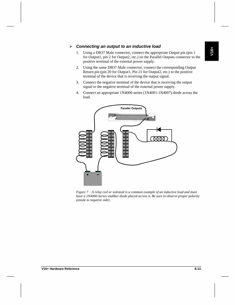
V16+ Hardware Reference 8-13
V16+
Connecting an output to an inductive load
1. Using a DB37 Male connector, connect the appropriate Output pin (pin 1
for Output1, pin 2 for Output2, etc.) on the Parallel Outputs connector to the
positive terminal of the external power supply.
2. Using the same DB37 Male connector, connect the corresponding Output
Return pin (pin 20 for Output1, Pin 21 for Output2, etc.) to the positive
terminal of the device that is receiving the output signal.
3. Connect the negative terminal of the device that is receiving the output
signal to the negative terminal of the external power supply.
4. Connect an appropriate 1N4000-series (1N4001-1N4007) diode across the
load.
Figure 7 – A relay coil or solenoid is a common example of an inductive load and must
have a 1N4000-Series snubber diode placed across it. Be sure to observe proper polarity (anode to negative side).

8-14 V16+ Hardware Reference
Video Synchronization
The V16+ is designed to extract the vertical frame clock from an external video
sync signal. This signal should be NTSC or PAL composite video at the
standard sync level of 4.1 volts peak-to-peak.
The sync signal is connected to the V16+ via a rear panel BNC connector. If
additional devices are to be wired to the same sync signal, a BNC “T” may be
used to daisy-chain the signal. If the V16+ is the last device in the chain, the
internal 75-Ohm terminator should be connected (factory default); otherwise it
should be disconnected.
A common sync connection scheme is to use the “Gen” output of a player to
drive the “C-Sync” inputs of another player, with the second “C-Sync”
connector of that player connecting to a third, and so on. The final player’s
second “C-Sync” connector would go to the V16+, which should have its
terminator enabled.
The V16+ may also work with “Black Burst Sync”, if its level is high enough.
Black burst sync is generally provided not at sync level, but at video level
(approximately 0.7 volts peak-to-peak). Signals at this level should not be
terminated with the 75-Ohm terminator. If you are trying to use a video level
signal, have the terminator disconnected, and still can’t get the sync to work
reliably, it is possible to increase the V16+ input sensitivity by removing R16.
Since this procedure is performed with wire cutters, it should not be undertaken
lightly. It also voids the warranty. But if it’s 3 AM in Abu Dhabi and your
show opens at dawn, what the heck.
Sync Termination
Composite sync signals contain high frequency components. When the signal
reaches the end of the line it has a tendency to reflect back toward the sync
generator. This reflected signal is undesirable because it degrades the “real”
signal. To prevent signal reflection, a terminating resistor is usually placed at
the end of the line.
The V16+ provides an internal 75-Ohm terminating resistor. The unit is shipped
from the factory with termination enabled (jumper installed).
Configuring sync termination
1. If the V16+ is the last unit in the daisy-chain, verify that W3 is present.
2. If the V16+ is NOT the last unit on the daisy-chain, remove W3.

V16+ Hardware Reference 8-15
V16+
Power Supply
The V16+ includes an external universal power supply that allows connection to
many domestic as well as international wall voltages (110VAC, 220VAC,
200VAC) without special configuration.
The power ratings for the V16+ external power supply are as follows:
Input: 100-250VAC; 50-60Hz; 0.7-0.3A
Output: +5V, 4.0A; +12V, 1.0A; -12V, 0.6A
Pin Connection
1 Common
2 N/C
3 +5V
4 -12V
5 +12V
Table 11 – V16+ Power jack connections.
Note When connecting the V16+ to power, DO NOT insert the power
connector into the MIDI In or MIDI Out jacks. This could damage the unit!

8-16 V16+ Hardware Reference
Firmware
The operating system that resides in the V16+ is called the “firmware”. Periodic
firmware upgrades are made in order to add new features, streamline operation,
and fix bugs. For pricing and availability of firmware upgrades, contact Alcorn
McBride.
Instead of purchasing your firmware upgrades, you can program them into
EPROMs yourself. The latest firmware can be downloaded from Alcorn
McBride’s WWW site on the Internet. The address is http://www.alcorn.com/
Upgrading show control firmware
1. Open the V16+ and locate socket U4 (It is labeled
“OPERATING SYSTEM FIRMWARE”).
2. Remove the old firmware EPROM from socket U4.
3. Install the new firmware EPROM into socket U4.
Show Memory When scripts are compiled and downloaded to the V16+, the data is stored in the
Show Memory. The V16+ comes standard with 32K of show memory, but for
larger shows (>4000 events) the memory may be upgraded to 64K. For pricing
and availability of show memory upgrades, contact Alcorn McBride.
Upgrading show memory
Socket U8 contains the standard 32K EEPROM. Socket U15 is available for
expansion memory.
1. Open the V16+ and locate chip sockets U8 and U15 (They are labeled
“SHOW DATA EEPROM 1” and “SHOW DATA EEPROM 2”).
2. To upgrade from 32K to 40K, install an 8K EEPROM (28C64) in U15.
3. To upgrade from 32K to 64K, install a 32K EEPROM (28C256) in U15.

V2+ Hardware Reference 10-1
V2+
V2+ Hardware Reference
The V2+ is the smallest of our “V” series controllers. It offers all of the same
types of resources as our V4+ and V16+, just fewer of them. It is ideally suited
for displays, trade shows and kiosks.

10-2 V2+ Hardware Reference
Specifications
Size XE "Size" Standard 1U rack mount (1.75” x 19” x 6.5”), 8 lbs
Power: 120 or 240 VAC (specify when ordering), 50 to 60 Hz
25 watts maximum.
UL listed Class 2 power adapter
Environment: 0 to 35 C (32 to 100 F)
0 to 90% relative humidity, non-condensing
Front Panel: 2x16 LCD Display
Power LED
Acknowledge (ACK) LED
Error LED
2 Serial Activity LEDs
8 Input Status LEDs
8 Output Status LEDs
8 Pushbuttons
Rear Panel: Programming Port DB-9M
2 Serial Ports DB-9M
MIDI Input 5-pin DIN Female
MIDI Output 5-pin DIN Female
Discrete I/O DB-37F
NTSC or PAL Sync Input BNC
Power Barrel Connector
Serial Ports: (2) RS-232C
300 baud - 38.4 Kbaud
7, 8, or 9 Data Bits
1 or 2 Stop Bits
All parity types
1 port can be configured as MIDI
Opto Inputs: (8) 24 VDC, 20 mA maximum
Reconfigurable for voltages down to 5 VDC or for pure
contact-closure operation. Trigger latency < 1 frame.
Driver Outputs: (8) Lamp drivers rated at 500mA each when used
individually, 150mA each if all in use.
Show Memory: 24 Kbyte EEPROM. Nonvolatile, robust memory retains
show data permanently with no battery backup required.

V2+ Hardware Reference 10-3
V2+
Serial Ports The V2+ provides two serial ports which may be configured as shown below:
Port Type Description Connector
0 RS-232 Programmer Port DB9M
1 RS-232 Port 1 DB9M
2 RS-232* / MIDI Port 2 DB9M / (2) 5 Pin DIN F
Table 1 – V2+ Ports located on the Rear Panel. *Factory Default Setting
Programmer Port
The Programmer Port is an RS-232C serial port used to program the V2+.
Pin Connection
2 RS-232 TXD
3 RS-232 RXD
5 GND
8 +12V Pull Up
Table 2 – Programmer port connections.
Port 1: RS-232
Port 1 is permanently configured as RS-232C.
Pin Connection
2 RS-232 RXD
3 RS-232 TXD
4 +12V Pull Up
5 GND
7 +12V Pull Up
Table 3 – Ports 1-15 connections for RS-232 operation.

10-4 V2+ Hardware Reference
Port 2: RS-232 or MIDI
Port 2 is factory configured as an RS-232C serial port, but can be reconfigured
as a MIDI port. When reconfigured, MIDI Input is received by the MIDI IN
port, and MIDI Output is sent out the MIDI OUT port. The MIDI Thru port
echoes the data received on MIDI IN.
Configuring Port 2 as MIDI
1. Place the jumper on W2 and W3 in the direction toward the “MIDI” text.
2. Configure Port 2 in WinScript as “MIDI”
3. Configure the baud rate of Port 2 in WinScript as 31250 baud
MIDI IN
Pin Connection
4 MIDI RX+
5 MIDI RX-
Table 4 – MIDI IN connections.
MIDI OUT and THRU
Pin Connection
2 GND
4 MIDI TX+
5 MIDI TX-
Table 5 – MIDI OUT and THRU connections.
Configuring Port 2 as RS-232
1. Place the jumpers on W2 and W3 in the direction toward the “RS-232” text.
LCD Display The V2+ includes a standard 2x16 (32 character) Backlit LCD Display. An
internal potentiometer is used to adjust the contrast (viewing angle) of the LCD.
Adjusting the LCD contrast
1. To make the display lighter, turn “CONTRAST” control VR1 clockwise.
2. To make the display darker, turn VR1 counter-clockwise.
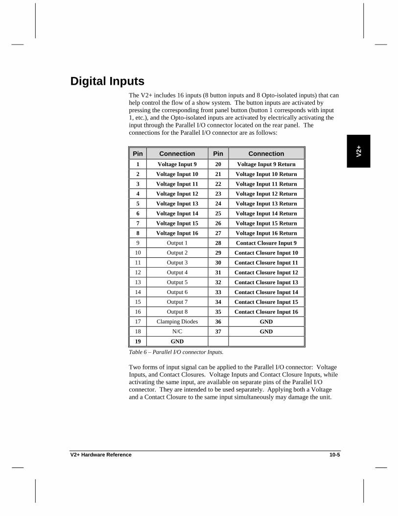
V2+ Hardware Reference 10-5
V2+
Digital Inputs The V2+ includes 16 inputs (8 button inputs and 8 Opto-isolated inputs) that can
help control the flow of a show system. The button inputs are activated by
pressing the corresponding front panel button (button 1 corresponds with input
1, etc.), and the Opto-isolated inputs are activated by electrically activating the
input through the Parallel I/O connector located on the rear panel. The
connections for the Parallel I/O connector are as follows:
Pin Connection Pin Connection
1 Voltage Input 9 20 Voltage Input 9 Return
2 Voltage Input 10 21 Voltage Input 10 Return
3 Voltage Input 11 22 Voltage Input 11 Return
4 Voltage Input 12 23 Voltage Input 12 Return
5 Voltage Input 13 24 Voltage Input 13 Return
6 Voltage Input 14 25 Voltage Input 14 Return
7 Voltage Input 15 26 Voltage Input 15 Return
8 Voltage Input 16 27 Voltage Input 16 Return
9 Output 1 28 Contact Closure Input 9
10 Output 2 29 Contact Closure Input 10
11 Output 3 30 Contact Closure Input 11
12 Output 4 31 Contact Closure Input 12
13 Output 5 32 Contact Closure Input 13
14 Output 6 33 Contact Closure Input 14
15 Output 7 34 Contact Closure Input 15
16 Output 8 35 Contact Closure Input 16
17 Clamping Diodes 36 GND
18 N/C 37 GND
19 GND
Table 6 – Parallel I/O connector Inputs.
Two forms of input signal can be applied to the Parallel I/O connector: Voltage
Inputs, and Contact Closures. Voltage Inputs and Contact Closure Inputs, while
activating the same input, are available on separate pins of the Parallel I/O
connector. They are intended to be used separately. Applying both a Voltage
and a Contact Closure to the same input simultaneously may damage the unit.

10-6 V2+ Hardware Reference
Voltage Inputs vs. Contact Closures
There are many advantages to using Voltage Inputs over Contact Closures.
First, a Contact Closure can only be located a short distance from the V2+.
Second, Contact Closures use the V2+’s own power supply, so external wiring
errors can damage the entire unit.
Figure 1 – Contact Closure Schematic.
Figure 2 – Voltage Input Schematic.
Configuration Maximum Distance
Contact Closures 10ft
Voltage Inputs Limited only by wire gauge
Table 7 – Voltage Inputs are advantageous for many reasons, including the distance at
which they are operational.

V2+ Hardware Reference 10-7
V2+
Input Wiring
Connecting a Voltage Input
1. Open the V2+ and verify that the correct Resistor Pack is installed in RP5
(see table 8)
2. Connect the appropriate wire from the Voltage Input signal pin (pin 1 for
Input9, pin 2 for Input10, etc.) to the positive terminal of the 24 VDC
external power supply.
3. Connect the negative terminal of the external power supply to one of the
terminals of the contact closure.
4. Connect the appropriate Voltage Input Return pin on the Parallel I/O
connector to the other terminal of the contact closure (pin 20 for Input9, Pin
21 for Input10, etc.)
Voltage Level Used Resistor Pack Value
5V 180 Ohm
12V 470 Ohm
24V 1.5K Ohm*
Table 8 – Recommended Resistor Pack values for Voltage Inputs.
* Factory Default Setting
Figure 3 – Sample connection for a Voltage Input to Input9 of the Parallel I/O connector.
The terminal blocks are used for power bussing and modularization of the input signals.

10-8 V2+ Hardware Reference
Connecting a Contact Closure
1. Connect the appropriate wire from the Input signal pin (pin 28 for Input9,
pin 29 for Input10, etc.) on the Parallel I/O connector to one of the
terminals of the external contact.
2. Connect one of the GND pins on the Parallel I/O connector to the other
terminal of the external contact.
Figure 4 – Sample connection for a Contact Closure Input to Input9 of the Parallel I/O
connector.

V2+ Hardware Reference 10-9
V2+
Digital Outputs
Output Connector
In addition to discrete inputs, the V2+ provides 8 transistor outputs (lamp
drivers) for discrete control. These outputs are capable of sinking up to 500 mA
each when used individually. The amount of current that each output can sink
decreases when the number of outputs being used at the same time increases.
For example: if all of the outputs are used at the same time they can only sink
150mA each.
The connections for the Parallel I/O connector are as follows:
Pin Connection Pin Connection
1 Voltage Input 9 20 Voltage Input 9 Return
2 Voltage Input 10 21 Voltage Input 10 Return
3 Voltage Input 11 22 Voltage Input 11 Return
4 Voltage Input 12 23 Voltage Input 12 Return
5 Voltage Input 13 24 Voltage Input 13 Return
6 Voltage Input 14 25 Voltage Input 14 Return
7 Voltage Input 15 26 Voltage Input 15 Return
8 Voltage Input 16 27 Voltage Input 16 Return
9 Output 1 28 Contact Closure Input 9
10 Output 2 29 Contact Closure Input 10
11 Output 3 30 Contact Closure Input 11
12 Output 4 31 Contact Closure Input 12
13 Output 5 32 Contact Closure Input 13
14 Output 6 33 Contact Closure Input 14
15 Output 7 34 Contact Closure Input 15
16 Output 8 35 Contact Closure Input 16
17 Clamping Diodes 36 GND
18 N/C 37 GND
19 GND
Table 9 – Parallel I/O connector Outputs.
Note When the outputs are used to drive inductive loads (relay coils, etc.), pin
17 can be connected to the powered side of the load to provide additional
snubber diode protection.

10-10 V2+ Hardware Reference
External Connection
Connecting an output to a non-inductive load
1. Connect the positive terminal of the external power supply to the positive
terminal of the device that is receiving the signal.
2. Connect the negative terminal of the power supply to one of the GND pins
on the Parallel I/O connector.
3. Connect the appropriate Output pin (pin 9 for Output1, pin 10 for Output2,
etc.) on the Parallel I/O connector to the negative terminal of the device that
is receiving the output signal
Figure 5 – An indicator lamp is a common example of a non-inductive load.

V2+ Hardware Reference 10-11
V2+
Connecting an output to an inductive load
1. Connect the positive terminal of the external power supply to the positive
terminal of the device that is receiving the signal.
2. If external snubber diodes are not used, connect the Clamping Diodes pin
(pin 17) on the Parallel I/O connector to the positive terminal of the external
power supply.
3. Connect the negative terminal of the power supply to one of the GND pins
on the Parallel I/O connector..
4. Connect the appropriate Output pin (pin 9 for Output1, pin 10 for Output2,
etc.) on the Parallel I/O connector to the negative terminal of the device that
is receiving the output signal.
Figure 6 – A relay coil or solenoid is a common example of an inductive load and must
have a 1N4000-Series snubber diode placed across it. Be sure to observe proper polarity (anode to negative side).

10-12 V2+ Hardware Reference
Power Supply
The V2+ includes an external power supply that allows connection to most
domestic wall voltages (110VAC). A 220VAC model is available upon request.
The power ratings for the V2+ external power supply are as follows:
Input: 120 VAC; 60Hz; 15 watts max.
Output: 9 VDC; 1A
Note Make sure that any power supply used with the V2+ is the correct voltage
and is configured correctly.
Firmware
The operating system that resides in the V2+ is called the “firmware”. Periodic
firmware upgrades are made in order to add new features, streamline operation,
and fix bugs. For pricing and availability of firmware upgrades, contact Alcorn
McBride.
Instead of purchasing your firmware upgrades, you can program them into
EPROMs yourself. The latest firmware can be downloaded from Alcorn
McBride’s WWW site on the Internet. The address is http://www.alcorn.com/
Upgrading show control firmware
1. Open the V2+ and locate socket U1.
2. Remove the old firmware EPROM from socket U1.
3. Install the new firmware EPROM into socket U1.

IO64 Hardware Reference 12-1
IO64
IO64 Hardware Reference
The IO64 is an intelligent I/O expansion unit which may also be used as a stand-
alone show controller. It provides a large number of inputs and outputs in a very
small package, and features easy to use rear panel terminal blocks. It is ideal for
I/O intensive applications such as process control.

12-2 IO64 Hardware Reference
Specifications
Size XE "Size" Standard 1U rack mount (1.75” x 19” x 5.5”), 3 lbs
Power: 100 to 250 VAC, 50 to 60 Hz, 25 watts maximum.
UL listed Class 2 power adapter
Environment: 0 to 35 C (32 to 100 F)
0 to 90% relative humidity, non-condensing
Front Panel: Power LED
Acknowledge (ACK) LED
Error LED
1 Serial Activity LED
32 Input Status LEDs
32 Output Status LEDs
Rear Panel: Host (Programmer) Serial Port DB-9M
Remote Serial Port DB-9M
5 Pin DIN MIDI Connector
Discrete I/O Phoenix Type Connectors
(Mating Connectors with Screw Terminals Included)
5 Pin DIN Power Connector
Serial Port: RS-232C
300 baud - 38.4 Kbaud
7, 8, or 9 Data Bits
1 or 2 Stop Bits
All parity types
Port may also be configured for RS-422/485 or MIDI
Opto Inputs: (32) 24 VDC, 20 mA maximum
Reconfigurable for voltages down to 5 operation.
Trigger latency < 1 frame.
Relay Outputs: (32) Contact Closures limited internally to 900 mA with
self-restoring polymer fuses.
Show Memory: 24 Kbyte EEPROM. Nonvolatile, robust memory retains
show data permanently with no battery backup required.

IO64 Hardware Reference 12-3
IO64
Serial Ports When used as an I/O expander, the IO64’s “Host” port connects to one of our
other show controllers (or any other serial port). When used as a show
controller, its “Host” port becomes a programming port.
The remote port may be configured for RS-232, RS-422/485 or MIDI operation.
Port Type Description Connector
0 RS-232 Host Port DB9M
1 RS-232* / 485 / MIDI Remote Port DB9M / 5 Pin DIN F
Table 1 – IO64 Ports located on the Rear Panel. *Factory Default Setting
Note RS-485 is used throughout this manual to denote ports that may be used
for both RS-422 and RS-485 communication.
Host Port
The Host Port is an RS-232C serial port used to program the IO64.
Pin Connection
2 RS-232 TXD
3 RS-232 RXD
5 GND
Table 2 – Programmer port connections

12-4 IO64 Hardware Reference
Remote Port: RS-232, RS-485, MIDI
The Remote Port is factory configured as an RS-232C serial port, but can be
reconfigured as an RS-485 or MIDI port. When reconfigured as a MIDI port,
MIDI Input and Output is received on and sent out the MIDI connector.
Pin RS-232 Connection RS-485 Connection
1 N/C N/C
2 RS-232 RXD N/C
3 RS-232 TXD N/C
4 N/C N/C
5 GND GND
6 N/C RS-485 TX+
7 N/C RS-485 TX-
8 N/C RS-485 RX+
9 N/C RS-485 RX-
Table 3 – Remote Port connections for RS-232 and RS-485 operation
Configuring the Remote Port as RS-485
1. Set jumper W1 to the “RS-485” position.
2. Set Jumper W3 to the RS-232 position. (This selects normal rather than
MIDI baud rates.)
3. It is often desirable to terminate RS-422 and RS-485 signals at the receiving
end. To terminate the line at the IO64 end, connect a 220 Ohm resistor
between pin 8 and pin 9 of Remote Port cable’s connector inside the
housing. To terminate the receiver at the remote end, connect a 220 Ohm
resistor across the RXD pins of the remote equipment.
Configuring the Remote Port as MIDI
1. Set jumper W1 to the “MIDI” position.
2. Set Jumper W3 to the MIDI position.
Configuring the Remote Port as RS-232
1. Set jumper W1 to the “RS-232” position
2. Set Jumper W3 to the RS-232 position.

IO64 Hardware Reference 12-5
IO64
MIDI Input/Output Cable
The IO64’s rear panel MIDI connector may be directly connected to a device
that sends MIDI data. In order to both send and receive MIDI Show Control
messages at the same time, a special MIDI I/O cable must be made to allow
MIDI Input and MIDI Output jacks to be available. The cable should look like
this:
Figure 1 – IO64 MIDI Input/Output Cable.
In addition, jumper W2 should be installed to provide the shield for the MIDI
output cable.

12-6 IO64 Hardware Reference
Digital Inputs The IO64 includes 32 Opto-isolated inputs that can help control the flow of a
show system. These inputs can be activated through the Phoenix Type Input
Connectors located on the rear panel.
Note The Opto-Inputs on the IO64 are polarity-sensitive. For a specific input
to be correctly connected, positive voltage must be connected to the top socket
of the Phoenix connector, and negative voltage must be connected to the bottom
socket.
Connecting an Input
1. Verify that the appropriate Resistor Pack is installed in each of the sockets
(see Tables 4 and 5 below)
2. Using a Male Phoenix connector, connect the appropriate wire from the
Input signal pin (top pin 1 for Input1, top pin 2 for Input2, etc.) to the
positive terminal of the external power supply.
3. Connect the negative terminal of the external power supply to one of the
terminals of the contact closure
4. Connect the appropriate Input Return pin to the other terminal of the contact
closure (bottom pin 1 for Input1, bottom pin 2 for Input2, etc.)
Example: External Switch
Figure 2 – An external switch or button is used to activate Input1.

IO64 Hardware Reference 12-7
IO64
Resistor Pack Inputs
RP8 1-8
RP6 9-16
RP12 17-24
RP10 25-32
Table 4 – Inputs that are affected by particular Resistor Pack values
Voltage Level Used Resistor Pack Value
5V 180 Ohm
12V 470 Ohm
24V 1.5K Ohm*
Table 5 – Recommended Resistor Pack values.
*Factory Default Setting

12-8 IO64 Hardware Reference
Digital Outputs The IO64 provides 32 Dry-Contact Relay Outputs for discrete control.
Note: The Relay Outputs on the IO64 are not polarity-sensitive; therefore,
positive and negative voltages may both be connected to either the top or bottom
socket of the Phoenix connector.
The Relay Outputs are fused at 900mA using self-restoring polymer fuses. If an
overload occurs, the fuse will open until the problem is corrected; then heal
itself.
Connecting an output to a non-inductive load
1. Using a Male Phoenix Connector, connect the appropriate Output pin (top
pin 1 for Output1, top pin 2 for Output2, etc.) on the Outputs Phoenix
Connector to the positive terminal of the external power supply.
2. Using a Phoenix Connector, connect the corresponding Output Return pin
(bottom pin 1 for Output1, bottom pin 2 for Output2, etc.) to the positive
terminal of the device that is receiving the output signal.
3. Connect the negative terminal of the device that is receiving the output
signal to the negative terminal of the external power supply.
Figure 3 – An indicator lamp is a common example of a non-inductive load.

IO64 Hardware Reference 12-9
IO64
Connecting an output to an inductive load
1. Using a Male Phoenix Connector, connect the appropriate Output pin (top
pin 1 for Output1, top pin 2 for Output2, etc.) on the Outputs Phoenix
Connector to the positive terminal of the external power supply.
2. Using a Phoenix Connector, connect the corresponding Output Return pin
(bottom pin 1 for Output1, bottom pin 2 for Output2, etc.) to the positive
terminal of the device that is receiving the output signal.
3. Connect the negative terminal of the device that is receiving the output
signal to the negative terminal of the external power supply.
4. Connect an appropriate 1N4000-series (1N4001-1N4007) diode across the
load.
Figure 4 – A relay or solenoid is a common example of an inductive load and must have
a 1N4000-Series snubber diode placed across it. Be sure to observe proper polarity (anode to negative side).

12-10 IO64 Hardware Reference
Power Supply
The IO64 includes an external universal power supply that allows connection to
many domestic as well as international wall voltages (110VAC, 220VAC,
200VAC) without special configuration.
The power ratings for the IO64 external power supply are as follows:
Input: 100-250VAC; 50-60Hz; 50 watts max
Output: +5V, 4.0A; +12V, 1.0A; -12V, 0.6A
Pin Connection
1 Common
2 N/C
3 +5V
4 -12V
5 +12V
Table 6 – IO64 Power jack connections
Note When connecting the IO64 to power, DO NOT insert the power
connector into the MIDI jack. This could damage the unit!
Firmware
The operating system that resides in the IO64 is called the “firmware”. Periodic
firmware upgrades are made in order to add new features, streamline operation,
and fix bugs. For pricing and availability of firmware upgrades, contact Alcorn
McBride.
Instead of purchasing your firmware upgrades, you can program them into
EPROMs yourself. The latest firmware can be downloaded from Alcorn
McBride’s WWW site on the Internet. The address is http://www.alcorn.com/
Upgrading show control firmware
1. Remove the old firmware EPROM from socket U4.
2. Install the new firmware EPROM into socket U4.
.

DMX Machine Hardware Reference 13-1
DM
X
Mach
ine
DMX Machine Hardware Reference
The DMX Machine™ is a complete stand-alone lighting controller. It is ideal as
a slave to another controller, or can be used by itself for small shows or
elaborate kiosks.

13-2 DMX Machine Hardware Reference
Specifications
Size XE "Size" Standard 1U rack mount (1.75” x 19” x 6.5”), 8 lbs
Power: 120 or 240 VAC (specify when ordering), 50 to 60 Hz
25 watts maximum.
UL listed Class 2 power adapter
Environment: 0 to 35 C (32 to 100 F)
0 to 90% relative humidity, non-condensing
Front Panel: Power LED
Acknowledge (ACK) LED
Error LED
Serial Activity LED
8 Pushbuttons
Rear Panel: Programming Port DB-9M
1 Serial Port DB-9M
1 DMX Output 5-pin XLR Female
Discrete Inputs DB-37F
Power Barrel Connector
Serial Port: RS-232C
300 baud - 38.4 Kbaud
7, 8, or 9 Data Bits
1 or 2 Stop Bits
All parity types
DMX Port: DMX-512 (1990) standard
Inputs: (16) TTL inputs, internally pulled up to +5 VDC, suitable
for contact-closure operation. Trigger latency < 1 frame.
Show Memory: 32 Kbyte EEPROM. Nonvolatile, robust memory retains
show data permanently with no battery backup required.

DMX Machine Hardware Reference 13-3
DM
X
Mach
ine
Serial Ports The DMX Machine provides serial ports which are configured as shown below:
Port Type Description Connector
0 RS-232 Programmer Port DB9M
1 RS-232 Port 1 DB9M
Table 1 – DMX Machine Ports located on the Rear Panel
Programmer Port
The Programmer Port is an RS-232C serial port used to program the
DMX Machine.
Pin Connection
2 RS-232 TXD
3 RS-232 RXD
5 GND
Table 2 – Programmer port connections
Port 1: RS-232
Port 1 is permanently configured as RS-232C.
Pin Connection
2 RS-232 RXD
3 RS-232 TXD
5 GND
Table 3 – Ports 1 connections for RS-232 operation

13-4 DMX Machine Hardware Reference
DMX Output Port The DMX Output port connections are as follows:
Pin Connection
1 Common (Shield)
2 DMX TX-
3 DMX TX+
4 N/C
5 N/C
Table 4 – DMX Out connections
The DMX line is a differential communications signal which conforms to
RS-485 standards. This means that it utilizes both positive and negative lines to
transmit a signal, thereby reducing is susceptibility to external noise. Even
though the DMX signals are well protected from external noise, they must be
protected from INTERNAL noise as well. When the DMX controller sends a
DMX signal down the line, that signal has a tendency to reflect back toward the
DMX unit once it reaches the end of the line. This “reflected” signal is harmful
because it can degrade the quality of real signals.
To prevent signal reflection, a 120 Ohm terminating resistor should be placed
across the positive and negative receive terminals (RXD+ and RXD-) of the
LAST receiver on the line. Placing the resistor across the pins will effectively
terminate the signal at the last unit while still allowing the last dimmer to receive
the signal. Many dimmer packs provide a built in resistor and switch for such
termination. Otherwise you will need a discrete resistor.
Figure 1 – A 120-Ohm Terminating Resistor is placed across the RXD+ and RXD- lines
of the Last Receiver.
Note Some DMX Dimmers provide a switch or jumper to activate internal
termination. If your Dimmers include this feature, do not place the terminating
resistor across the receive terminals.

DMX Machine Hardware Reference 13-5
DM
X
Mach
ine
Digital Inputs The DMX Machine includes 16 contact closure inputs that can help control the
flow of a show system. These inputs are activated by connecting a contact
closure from the input pins on the rear panel Parallel Input connector to ground.
(The eight front panel buttons duplicate the function of the first eight contact
closure inputs – button 1 corresponds with input 1, etc.) The connections for the
Parallel Input connector are as follows:
Pin Connection Pin Connection
1 Contact Closure Input 1 20 GND
2 Contact Closure Input 2 21 GND
3 Contact Closure Input 3 22 GND
4 Contact Closure Input 4 23 GND
5 Contact Closure Input 5 24 GND
6 Contact Closure Input 6 25 GND
7 Contact Closure Input 7 26 GND
8 Contact Closure Input 8 27 GND
9 Contact Closure Input 9 28 GND
10 Contact Closure Input 10 29 GND
11 Contact Closure Input 11 30 GND
12 Contact Closure Input 12 31 GND
13 Contact Closure Input 13 32 GND
14 Contact Closure Input 14 33 GND
15 Contact Closure Input 15 34 GND
16 Contact Closure Input 16 35 GND
17 N/C 36 N/C
18 N/C 37 N/C
19 N/C
Table 5 – Parallel Input connector Inputs

13-6 DMX Machine Hardware Reference
Input Wiring
Connecting a Contact Closure
1. Connect the appropriate wire from the Input signal pin (pin 1 for Input1,
pin 2 for Input2, etc.) on the Parallel I/O connector to one of the terminals
of the contact closure.
2. Connect one of the GND pins on the Parallel I/O connector to the other
terminal of the contact closure.
Figure 2 – Sample connection for a Contact Closure connected to Input1 of the Parallel
Inputs connector

DMX Machine Hardware Reference 13-7
DM
X
Mach
ine
Power Supply
The DMX Machine includes an external power supply that allows connection to
most domestic wall voltages (110VAC). A 220VAC model is available upon
request.
The power ratings for the DMX Machine external power supply are as follows:
Input: 120 VAC; 60Hz; 15 watts max.
Output: 9 VDC; 1A
Note Make sure that any power supply used with the DMX Machine is the
correct voltage and is configured correctly.
Firmware
The operating system that resides in the DMX Machine is called the “firmware”.
Periodic firmware upgrades are made in order to add new features, streamline
operation, and fix bugs. For pricing and availability of firmware upgrades,
contact Alcorn McBride.
Instead of purchasing your firmware upgrades, you can program them into
EPROMs yourself. The latest firmware can be downloaded from Alcorn
McBride’s WWW site on the Internet. The address is http://www.alcorn.com/
Upgrading show control firmware
1. Open the DMX Machine and locate socket U1
2. Remove the old firmware EPROM from socket U1
3. Install the new firmware EPROM into socket U1

13-8 DMX Machine Hardware Reference

SMPTE Machine Hardware Reference 14-1
SM
PT
E
Mach
ine
SMPTE Machine Hardware Reference
The SMPTE Machine™ provides SMPTE reading and generation capabilities to
all Alcorn McBride show controllers. It allows any sequences to be triggered at
predefined timecodes.
The SMPTE Machine is ideal for installations where timecode is used to
synchronize many disparate pieces of equipment.

14-2 SMPTE Machine Hardware Reference
Specifications
Size XE "Size" Standard 1U rack mount (1.75” x 19” x 6.5”), 8 lbs
Power: 120 or 240 VAC (specify when ordering), 50 to 60 Hz
25 watts maximum.
UL listed Class 2 power adapter
Environment: 0 to 35 C (32 to 100 F)
0 to 90% relative humidity, non-condensing
Front Panel: 2x16 LCD Display
Power LED
Fault LED
Lock LED
Generate LED
3 Pushbuttons
Rear Panel: Programming Port DB-9M
2 Serial Ports DB-9M
MIDI Input 5-pin DIN Female
MIDI Output 5-pin DIN Female
MIDI Thru 5-pin DIN Female
Discrete I/O DB-37F
NTSC or PAL Sync Input BNC
Power Barrel Connector
Serial Ports: (2) RS-232C
300 baud - 38.4 Kbaud
7, 8, or 9 Data Bits
1 or 2 Stop Bits
All parity types
1 port can be configured as MIDI
Opto Inputs: (4) 24 VDC, 20 mA maximum
Reconfigurable for voltages down to 5 VDC or for pure
contact-closure operation. Trigger latency < 1 frame.
Driver Outputs: (3) Lamp drivers rated at 500mA each when used
individually, 150mA each if all in use.
SMPTE Output: 4V p-p max into 600 ohms (adjustable).
Trigger Memory: Nonvolatile, robust EEPROM memory retains trigger data
permanently with no battery backup required.

SMPTE Machine Hardware Reference 14-3
SM
PT
E
Mach
ine
Serial Ports The SMPTE Machine provides two serial ports, which may be configured as
shown below:
Port Type Description Connector
0 RS-232 Programmer Port DB9M
1 RS-232 Control Port DB9M
2 RS-232 / MIDI* Control Port DB9M / (2) 5 Pin DIN F
Table 1 – SMPTE Machine Ports located on the Rear Panel. *Factory Default Setting
Programmer Port
The Programmer Port is an RS-232C serial port used to program the SMPTE
Machine.
Pin Connection
2 RS-232 TXD
3 RS-232 RXD
5 GND
8 +12V Pull Up
Table 2 – Programmer port connections.
Port 1: RS-232
Port 1 is factory configured as an RS-232C serial port.
Pin Connection
2 RS-232 RXD
3 RS-232 TXD
4 +12V Pull Up
5 GND
7 +12V Pull Up
Table 3 – Port 2 connections for RS-232 operation.

14-4 SMPTE Machine Hardware Reference
Port 2: RS-232 or MIDI
Port 2 is factory configured as a MIDI port, but can be reconfigured as an RS-
232C serial port. For RS-232 use the connections are provided on a male DB-9
connector. For MIDI, they are provided on three 5-pin DIN connectors. When
configured for MIDI, MIDI Input is received by the MIDI IN port, and MIDI
Output is sent out the MIDI OUT port. The MIDI Thru port echoes the data
received on MIDI IN.
Configuring Port 2 as RS-232
1. Place the jumpers on W2 and W3 in the direction toward the “RS-232” text.
Pin Connection
2 RS-232 RXD
3 RS-232 TXD
4 +12V Pull Up
5 GND
7 +12V Pull Up
Table 4 – Port 2 connections for RS-232 operation.
Configuring Port 2 as MIDI
1. Place the jumper on W2 and W3 in the direction toward the “MIDI” text.
MIDI IN
Pin Connection
4 MIDI RX+
5 MIDI RX-
Table 5 – MIDI IN connections.
MIDI OUT and THRU
Pin Connection
2 GND
4 MIDI TX+
5 MIDI TX-
Table 6 – MIDI OUT and THRU connections.

SMPTE Machine Hardware Reference 14-5
SM
PT
E
Mach
ine
SMPTE The SMPTE Machine reads SMPTE using a 3 pin XLR female connector, and
generates it through a 3 pin XLR male.
SMPTE IN
Pin Connection
1 GND
2 Signal +
3 Signal -
Table 7 – SMPTE IN connections.
SMPTE OUT
Pin Connection
1 GND
2 Signal +
3 Signal -
Table 8 – SMPTE OUT.
SMPTE Output Signal Level
Switch SW9 selects the SMPTE Output Signal Level. Only one position of the
switch should be set to “ON” at a time.
SMPTE OUTPUT LEVEL SW9
Position Output Level (volts peak-to-peak)
1 4.0
2 3.5
3 3.0
4 2.5
5 2.0
Table 9 – SMPTE Output Level Adjustment.
Values shown assume a 600-Ohm balanced load.

14-6 SMPTE Machine Hardware Reference
SMPTE Read/Generate Sync Source
Jumper W1 Selects the SMPTE Sync Source. When reading SMPTE, this
jumper connects the incoming SMPTE signal to the SMPTE Machine. This is
the factory default position for W1. When generating SMPTE this jumper needs
to be changed if the generated SMPTE is to lock to external video sync. If the
generated SMPTE does not need to be video-locked, the position of this jumper
doesn’t matter.
Selecting Incoming SMPTE as a Sync Source (Reading Only)
1. Set Jumper W1 to the “SMPTE” position to read external SMPTE signal.
Selecting Video Sync as a Sync Source (Generating Only)
2. Set Jumper W1 to the “VIDEO” position to lock generated SMPTE to a
composite video sync signal.
LCD Display The SMPTE Machine includes a standard 2x16 (32 character) Backlit LCD
Display. An internal potentiometer is used to adjust the contrast (viewing angle)
of the LCD.
Adjusting the LCD contrast
1. To make the display lighter, turn “CONTRAST” control VR1 clockwise.
2. To make the display darker, turn VR1 counter-clockwise.

SMPTE Machine Hardware Reference 14-7
SM
PT
E
Mach
ine
Digital Inputs The SMPTE Machine includes 3 front panel buttons and 8 Opto-isolated inputs
that control the unit’s behavior. The buttons start, pause and reset the SMPTE
timecode. The Opto-isolated inputs are activated by electrically activating the
input through the Parallel I/O connector located on the rear panel.
The connections for the Parallel I/O connector are as follows:
Pin Connection Pin Connection
1 “Start” Voltage Input 20 “Start” Voltage Input Return
2 “Pause” Voltage Input 21 “Pause” Voltage Input Return
3 “Reset” Voltage Input 22 “Reset” Voltage Input Return
4 Not Used 23 Not Used
5 “Idle” Voltage Input 24 “Idle” Voltage Input 12 Return
6 Not Used 25 Not Used
7 Not Used 26 Not Used
8 Not Used 27 Not Used
9 “Running” Output 28 “Start” Contact Closure Input
10 “Fault” Output 29 “Pause” Contact Closure Input
11 “Ready” Output 30 “Reset” Contact Closure Input
12 Not Used 31 Not Used
13 Not Used 32 “Idle” Contact Closure Input
14 Not Used 33 Not Used
15 Not Used 34 Not Used
16 Not Used 35 Not Used
17 Clamping Diodes 36 GND
18 N/C 37 GND
19 GND
Table 10 – Parallel I/O connector Inputs.
Two forms of input signal can be applied to the Parallel I/O connector: Voltage
Inputs, and contact closures. Voltage Inputs and contact closure inputs, while
activating the same input, are available on separate pins of the Parallel I/O
connector. We do not recommend using both types of input simultaneously.

14-8 SMPTE Machine Hardware Reference
Voltage Inputs vs. Contact Closures
There are many advantages to using Voltage Inputs over Contact Closures.
First, a Contact Closure can only be located a short distance from the SMPTE
Machine. Second, Contact Closures use the SMPTE Machine’s own power
supply, so external wiring errors can damage the entire unit.
Figure 1 – Contact Closure Schematic.
Figure 2 – Voltage Input Schematic.
Configuration Maximum Distance
Contact Closures 10ft
Voltage Inputs Limited only by wire gauge
Table 11 – Voltage Inputs are advantageous for many reasons, including the distance at
which they are operational.

SMPTE Machine Hardware Reference 14-9
SM
PT
E
Mach
ine
Input Wiring
Connecting a Voltage Input
1. Open the SMPTE Machine and verify that the correct Resistor Pack is
installed in RP5 (see table 11).
2. Connect the appropriate wire from the Voltage Input signal pin (pin 1 for
“Start”, pin 3 for “Reset”, etc.) to the positive terminal of the 24 VDC
external power supply.
3. Connect the negative terminal of the external power supply to one of the
terminals of the contact closure.
4. Connect the appropriate Voltage Input Return pin on the Parallel I/O
connector to the other terminal of the contact closure (pin 20 for “Start”, Pin
22 for “Reset”, etc.)
Voltage Level Used Resistor Pack Value
5V 180 Ohm
12V 470 Ohm
24V 1.5K Ohm*
Table 12 – Recommended Resistor Pack values for Voltage Inputs.
* Factory Default Setting
Figure 3 – Sample connection for a Voltage Input to the “Start” input of the Parallel I/O
connector. The terminal blocks are used for power bussing and modularization of the
input signals.

14-10 SMPTE Machine Hardware Reference
Connecting a Contact Closure
1. Connect the appropriate wire from the Input signal pin (pin 28 for “Start”,
pin 30 for “Reset”, etc.) on the Parallel I/O connector to one of the
terminals of the contact closure.
2. Connect one of the GND pins on the Parallel I/O connector to the other
terminal of the contact closure.
Figure 4 – Sample connection for a Contact Closure Input to the “Start” input of the
Parallel I/O connector

SMPTE Machine Hardware Reference 14-11
SM
PT
E
Mach
ine
Digital Outputs
Output Connector
In addition to discrete inputs, the SMPTE Machine provides transistor outputs
(lamp drivers) that indicate the unit’s state. These outputs are capable of sinking
up to 500 mA each.
The connections for the Parallel I/O connector are as follows:
Pin Connection Pin Connection
1 “Start” Voltage Input 20 “Start” Voltage Input Return
2 “Pause” Voltage Input 21 “Pause” Voltage Input Return
3 “Reset” Voltage Input 22 “Reset” Voltage Input Return
4 Not Used 23 Not Used
5 “Idle” Voltage Input 24 “Idle” Voltage Input 12 Return
6 Not Used 25 Not Used
7 Not Used 26 Not Used
8 Not Used 27 Not Used
9 “Running” Output 28 “Start” Contact Closure Input
10 “Fault” Output 29 “Pause” Contact Closure Input
11 “Ready” Output 30 “Reset” Contact Closure Input
12 Not Used 31 Not Used
13 Not Used 32 “Idle” Contact Closure Input
14 Not Used 33 Not Used
15 Not Used 34 Not Used
16 Not Used 35 Not Used
17 Clamping Diodes 36 GND
18 N/C 37 GND
19 GND
Table 13 – Parallel I/O connector Outputs
Note When the outputs are used to drive inductive loads (relay coils, etc.), pin
17 can be connected to the powered side of the load to provide additional
snubber diode protection.

14-12 SMPTE Machine Hardware Reference
External Connection
Connecting an output to a non-inductive load
1. Connect the positive terminal of the external power supply to the positive
terminal of the device that is receiving the signal.
2. Connect the negative terminal of the power supply to one of the GND pins
on the Parallel I/O connector.
3. Connect the appropriate Output pin (pin 9 for “Running”, pin 10 for
“Fault”, etc.) on the Parallel I/O connector to the negative terminal of the
device that is receiving the output signal.
Figure 5 – An indicator lamp is a common example of a non-inductive load. This one is
connected to the “Running” output.

SMPTE Machine Hardware Reference 14-13
SM
PT
E
Mach
ine
Connecting an output to an inductive load
1. Connect the positive terminal of the external power supply to the positive
terminal of the device that is receiving the signal.
2. Connect the negative terminal of the power supply to one of the GND pins
on the Parallel I/O connector.
3. Connect the appropriate Output pin (pin 9 for “Running”, pin 10 for
“Fault”, etc.) on the Parallel I/O connector to the negative terminal of the
device that is receiving the output signal.
Figure 6 – A relay coil or solenoid is a common example of an inductive load and must
have a 1N4000-Series snubber diode placed across it. Be sure to observe proper polarity (anode to negative side).

14-14 SMPTE Machine Hardware Reference
Video Synchronization
The SMPTE Machine is designed to extract the vertical frame clock from an
external video sync signal. This feature is only used when generating SMPTE
and locking the generated signal to Video sync. This signal should be NTSC or
PAL composite video at the standard sync level of 4.1 volts peak-to-peak.
The sync signal is connected to the SMPTE Machine via a rear panel BNC
connector. If additional devices are to be wired to the same sync signal, a BNC
“T” may be used to daisy-chain the signal. If the SMPTE Machine is the last
device in the chain, the internal 75-Ohm terminator should be connected (factory
default); otherwise it should be disconnected.
A common sync connection scheme is to use the “Gen” output of player to
drive the “C-Sync” inputs of another player, with the second “C-Sync”
connector of that player connecting to a third, and so on. The final player’s
second “C-Sync” connector would go to the SMPTE Machine, which needs to
have its terminator enabled.
The SMPTE Machine may also work with “Black Burst Sync”, if its level is
high enough. Black burst sync is generally provided not at sync level, but at
video level (approximately 0.7 volts peak-to-peak). Signals at this level should
not be terminated with the 75-Ohm terminator. If you are trying to use a video
level signal, have the terminator disconnected, and still can’t get the sync to
work reliably, it is possible to increase the SMPTE Machine input sensitivity by
removing R23. Since this procedure is performed with wire cutters, it should
not be undertaken lightly. It also voids the warranty. But if it’s 3 AM in Abu
Dhabi and your show opens at dawn, what the heck.
Sync Termination
Composite sync signals contain high frequency components. When the signal
reaches the end of the line it has a tendency to reflect back toward the sync
generator. This reflected signal is undesirable because it degrades the “real”
signal. To prevent signal reflection, a terminating resistor is usually placed at
the end of the line.
The SMPTE Machine provides an internal 75-Ohm terminating resistor. The
unit is shipped from the factory with termination enabled (jumper installed).
Configuring sync termination
1. If the SMPTE Machine is the last unit in the daisy-chain, verify that W6 is
present.
2. If the SMPTE Machine is NOT the last unit on the daisy-chain, remove W6.

SMPTE Machine Hardware Reference 14-15
SM
PT
E
Mach
ine
Power Supply
The SMPTE Machine includes an external power supply that allows connection
to most domestic wall voltages (110VAC). A 220VAC model is available upon
request.
The power ratings for the SMPTE Machine external power supply are as
follows:
Input: 120 VAC; 60Hz; 15 watts max.
Output: 9 VDC; 1A
Note Make sure that any power supply used with the SMPTE Machine is the
correct voltage and is configured correctly.
Firmware
The operating system that resides in the SMPTE Machine is called the
“firmware”. Periodic firmware upgrades are made in order to add new features,
streamline operation, and fix bugs. For pricing and availability of firmware
upgrades, contact Alcorn McBride.
Instead of purchasing your firmware upgrades, you can program them into
EPROMs yourself. The latest firmware can be downloaded from Alcorn
McBride’s WWW site on the Internet. The address is http://www.alcorn.com/
Upgrading show control firmware
1. Open the SMPTE Machine and locate socket U1.
2. Remove the old firmware EPROM from socket U1.
3. Install the new firmware EPROM into socket U1.

14-16 SMPTE Machine Hardware Reference

15-1 Appendix A – Adding User-Defined Serial Protocols
Ap
pen
dic
es
A
Appendix A – Adding User-Defined Serial Protocols
Alcorn McBride Show Controllers can communicate with countless types of
serial devices. Information on how these devices communicate is located in
“Protocol Files”.
Protocol Files for many devices are included with WinScript and allow you to
program your show quickly and easily by using device-specific events that are
built into serial messages and sent to the device at the specified time.
The real power of Protocol Files is that you can create your own. You can
create events with up to four parameters that are automatically built into a valid
serial message by WinScript and sent by your Show Controller.
If you come up with a great new Protocol File, send it to us! Users are
constantly raising the bar on Alcorn McBride Show Controllers, so your
Protocol File could be valuable to other users. Good Luck!
In this section you will find:
Instructions for creating your own Protocol File
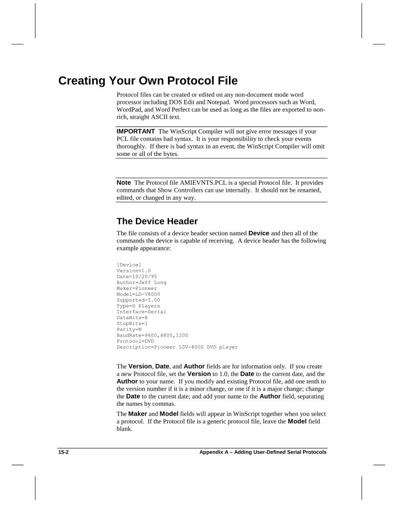
15-2 Appendix A – Adding User-Defined Serial Protocols
Creating Your Own Protocol File Protocol files can be created or edited on any non-document mode word
processor including DOS Edit and Notepad. Word processors such as Word,
WordPad, and Word Perfect can be used as long as the files are exported to non-
rich, straight ASCII text.
IMPORTANT The WinScript Compiler will not give error messages if your
PCL file contains bad syntax. It is your responsibility to check your events
thoroughly. If there is bad syntax in an event, the WinScript Compiler will omit
some or all of the bytes.
Note The Protocol file AMIEVNTS.PCL is a special Protocol file. It provides
commands that Show Controllers can use internally. It should not be renamed,
edited, or changed in any way.
The Device Header
The file consists of a device header section named Device and then all of the
commands the device is capable of receiving. A device header has the following
example appearance:
[Device]
Version=1.0
Date=10/20/95
Author=Jeff Long
Maker=Pioneer
Model=LD-V8000
Supported=5.00
Type=D Players
Interface=Serial
DataBits=8
StopBits=1
Parity=N
BaudRate=9600,4800,1200
Protocol=DVD
Description=Pioneer LDV-8000 DVD player
The Version, Date, and Author fields are for information only. If you create
a new Protocol file, set the Version to 1.0, the Date to the current date, and the
Author to your name. If you modify and existing Protocol file, add one tenth to
the version number if it is a minor change, or one if it is a major change; change
the Date to the current date; and add your name to the Author field, separating
the names by commas.
The Maker and Model fields will appear in WinScript together when you select
a protocol. If the Protocol file is a generic protocol file, leave the Model field
blank.

15-3 Appendix A – Adding User-Defined Serial Protocols
Ap
pen
dic
es
A
The Supported field indicates what firmware revision this protocol will work
under. Most protocols, especially straight ASCII ones intended for DVD or CD
players will work since rev 5.00. If the device requires firmware modification to
work, the Protocol field will be changed to that new type, and the rev number
of the Supported field will indicate that version of firmware. If a user
attempts to use this protocol, and downloads to a Show Controller with firmware
prior to this field, a compile/download error will alert the user that this unit will
not support these commands.
The Type field is currently for information only, but will eventually be used as
a description when a user right clicks on a protocol and selects "Properties". Try
to match this field with other similar devices in other Protocol files. There is no
right or wrong text to put here.
The Interface field determines what kind of device it is, and what kinds of
fields will follow. The two current possible choices for Interface are Serial
and SCSI. If the Interface is Serial, then the DataBits, StopBits, Parity, and
BaudRate fields should follow. If the interface is SCSI, then the Address
field should follow.
The DataBits field ( for Serial only ) determines the number of bits in the serial
data frame used for data. The three possible choices for DataBits are 7, 8, and
9. If the device supports multiple types, then separate them by commas.
The StopBits field ( for Serial only ) determines the number of bits in the serial
data frame used as an end-of-frame marker. The two possible choices for
StopBits are 1 and 2. . If the device supports both types, then separate them
by commas.
The Parity field ( for Serial only ) determines whether or not a parity bit exists
in the serial data frame used for parity checking, and if so, whether it is even or
odd parity. The three possible choices for Parity are N, E, and O. If the device
supports multiple types, then separate them by commas.
The BaudRate field ( for Serial only ) determines the speed of transmission of
the serial frame bits in bits per second. The possible choices for BaudRate are
300, 1200, 2400, 4800, 9600, 19200, and 38400. In the case of a MIDI serial
port, the only possible choice is 31250. If the device supports multiple types,
then separate them by commas.
The Address field ( for SCSI only ) determines what address the SCSI device
is set to. The possible choices for Address are 0, 1, 2, 3, 4, 5, 6, and 7. If the
device supports multiple types, then separate them by commas.
The Protocol field determines what method the Show Controller uses to send
out the bytes. For example,
the Alcorn9 protocol type tells the Show Controller to turn on the ninth bit on
the first and last bytes of each message. The possible choices for Protocol are
Alcorn9, Alcorn8, Custom, ReproBus, DVD, MIDI, ESERTC, and SonyCDROM.
Only one of these should be selected here. In general, most users will choose
the DVD, Custom, or MIDI protocol type. The only difference between DVD
and Custom is that the Show Controller expects to have tight communication
with the device, and often expect Acknowledges back from the device.

15-4 Appendix A – Adding User-Defined Serial Protocols
Device-Specific Events
Device-specific events are the meat of the Protocol file and can be quite
complicated. These events take what the user entered in WinScript's event
editor and convert the entered "Data" column information into data the protocol
will send out the port to the device. The MessageOut event is the only event
that is generally found in all Protocol files. This event ensures that the user
can—without changing the Protocol file—at least send out bytes to the device.
Here is the MessageOut event exactly as it could appear in your Protocol File:
[MessageOut]
description=Sends a user-defined message out the port
param1=port, "A valid Port"
param2=datastring|string, "A valid Data or local String"
message=@string(param2)
Making Events Efficient and Compact
Other than learning how to create each event using correct syntax, there are a
few basic guidelines that you should follow in creating events.
Create event names that comply or are similar to existing WinScript events.
The events that are used for most media players are Spinup, Spindown,
Search, Play, Still, Mute, etc. If you have some other device like a
matrix switcher, a Patch event name is appropriate. If your device is
unique, and no other Protocol file exists with a similar device/event set,
then you can choose your own name.
Choose event names that are short, to the point, and fit into context. A
DoYourStuff event name leaves much to be desired.
Try to orchestrate parameters of events so that their order makes logical
sense and requires the fewest events.
Create multiple variations of the same event if the arguments for the same
operation are mutually exclusive. Also create multiple variations of the
same event if some parameters are optional.
Creating New Events
Here is a simple Play event:
[Play:UntilFrame]
description=Plays from the current location to a frame number
supported=5.00
param1=port, "A valid Port"
param2=framestring, "A valid Frame number"
message=h02 "OPL:F" @string(param2) h03
retries=1
timeout=18000
completionack=h06
The name of the event is in brackets [Play:UntilFrame]. The sub-name is the
optional name following the colon in the brackets [Play:UntilFrame]. This

15-5 Appendix A – Adding User-Defined Serial Protocols
Ap
pen
dic
es
A
sub-name is required only when you have several versions of the same event.
This sub-name should be unique from other sub-names of this same event, and
should also be as meaningful as possible. In this case [Play:UntilFrame]
means play the disc until a certain frame is reached ( which is an argument to the
event ). The colon is only required when a sub-name is included.
The Description field becomes the explanatory text that is displayed in Event
Wizard.
The Supported field has the same purpose as it does in the [Device] header
except for it applies to the event itself. Therefore it is possible to have a
Protocol file that is defined to be supported under firmware revision 5.30, but
some of the events only work under revision 5.50 and later. The compiler first
checks the Protocol, and then the individual event. Under most circumstances,
the Supported field is not needed in each event for user defined protocols, and
can be omitted.
The Param fields of the event have four purposes:
Qualify the data, making sure it conforms to the requested type
Translate the actual data the user entered into a particular format in the
compiler's temporary buffer.
Describe an error message to display if the data does not qualify correctly
Describe the correct parameter to enter in the field (used by Event Wizard)
param1=port, "A valid Port"
param2=framestring, "A valid Frame number"
In this case, the first parameter must be a valid port name. The compiler looks
up the text put into the first parameter and verifies that there is a valid port with
that name in the Configuration | Ports window. If there is no port with that
name, the compiler will display the error following the qualifier. If there is, the
compiler will stuff one byte into the compiler's temporary buffer—which will be
the index of the port in question. The second parameter must be a valid frame
number-- the compiler confirms that the text entered is all digits, and less than
the maximum number of frames. If it is, it stuffs the frame number in ASCII
into the compiler's temporary buffer. If it isn't, the error message will be
displayed.

15-6 Appendix A – Adding User-Defined Serial Protocols
Note WinScript does not require parameters to be in specific column numbers,
as long as multiple parameters are placed in order. If the event requires two
parameters for example, the data can be put into column 2 and 4 ( leaving 1 and
3 blank ) as long as the data in column 1 matches the first parameter, and
column 4 matches the second parameter.
Param fields are important because of the fact that they perform an operation
as well as qualify the data. They take the data the user enters and puts it in a
format the message field can take and perform another operation on. The
combination of the param and message field processes are what make the
serial messages come out correctly.
Here are the possible param field choices: input, output, flag, var, port,
datastring, lcdstring, string, seq, byte, word, bytelabel, bytetime, framestring,
timestring, trackstring, and contains. In all cases, if the compiler does not
qualify the data, then the corresponding message is displayed if it exists. If the
compiler does qualify the data, the compiler performs different operations on the
parameter, depending on what the param field is. The following is a
description of each of the following param types:
input – Must match the name of an input in the Configuration | Inputs
window. Puts one byte in the compiler buffer which is the index of that
input.
output – Must match the name of an output in the Configuration | Outputs
window. Puts one byte in the compiler buffer which is the index of that
output.
flag – Must match the name of a flag in the Configuration | Flags window.
Puts one byte in the compiler buffer which is the index of that flag.
var – Must match the name of a variable in the Configuration | Variables
window. Puts one byte in the compiler buffer which is the index of that
variable.
port – Must match the name of a port in the Configuration | Ports window.
Puts one byte in the compiler buffer which is the index of that port.
sequence – Must match the name of a sequence in the Sequence List
window. Puts one byte in the compiler buffer which is the index of that
sequence.
remoteinput – Must match the name of an input in the Configuration |
Inputs window of the remote script connected to a porttyperemote as
param1. Puts one byte in the compiler buffer which is the index of that
input.
remoteoutput – Must match the name of an output in the Configuration |
Outputs window of the remote script connected to a porttyperemote as
param1. Puts one byte in the compiler buffer which is the index of that
output.

15-7 Appendix A – Adding User-Defined Serial Protocols
Ap
pen
dic
es
A
remoteflag – Must match the name of a flag in the in the Configuration |
Flags window of the remote script connected to a porttyperemote as
param1. Puts one byte in the compiler buffer which is the index of that flag.
remotevar – Must match the name of a variable in the Configuration |
Variables window of the remote script connected to a porttyperemote as
param1. Puts one byte in the compiler buffer which is the index of that
variable.
remoteport – Must match the name of a port in the Configuration | Ports
window of the remote script connected to a porttyperemote as param1. Puts
one byte in the compiler buffer which is the index of that port.
remotesequence – Must match the name of a sequence in the Sequence
List window of the remote script connected to a porttyperemote as param1.
Puts one byte in the compiler buffer which is the index of that sequence.
porttyperemote – Must be a valid local Alcorn 9 Bit Control port with a
valid Script attached to it.
bytelabel – Must match the name of a label in the Events window, and fit
into a single byte. The label must be less than 128 events away from the
current event. Puts one byte in the compiler buffer which is the offset in
bytes to that label.
bytetime – Must be a valid time that fits into one byte. Any time (
whether entered in absolute frames FFF, or time SS.FF ) is acceptable, up to
255 frames. The maximum time varies depending on the frame rate
selected in the Show Controller. For example, with a running frame rate of
30fps, the maximum time is 8 seconds, 15 frames. Puts one byte in the
compiler buffer which is the number of frames specified.
byte – Must be a valid number between 0 and 255 inclusive. The number
can be entered in decimal, hexadecimal, or percentage. For example, the
number 128 could be entered as 128 for decimal, 0x80, h80, or 80h for
hexadecimal, or 50% for percentage. Puts one byte in the compiler buffer
which is the number entered.
Note The param byte may have an optional argument which is a tighter
specification on the number. For example, paramX=byte(15,32) would
require the number entered to be larger than 14 and smaller than 33 to be valid.
word– Must be a valid number between 0 and 65535 inclusive. The
number can be entered in decimal, hexadecimal, or percentage. For
example, the number 49152 could be entered as 49152 for decimal,
0xC000, hC000, or EC000h for hexadecimal, or 75% for percentage.
Puts two bytes in the compiler buffer which is the number entered.
Note As in byte, the param word may have an optional argument which is a
tighter specification on the number.
string – Accepts any correctly formatted string. The string can consist of
any combination of decimal, hex, or percentage numbers, and text data. For

15-8 Appendix A – Adding User-Defined Serial Protocols
example, the string "HELLO" 0xAA 50 0 "GOODBYE" h2E is perfectly
valid. The compiler changes all the characters in quotes into ASCII bytes,
and puts the entire string into the compiler buffer.
“literal” – Accepts a string which is exactly what is specified, non-case
sensitive. For example, if the user entered "bAnK1" for the parameter, and
the param field is ParamX="bank1" the parameter will validate. The
compiler changes all the characters in quotes into ASCII bytes, and puts the
entire string into the compiler buffer.
datastring – Must match the name of a data string in the Configuration | Data Strings window. The data string must conform to the same
restrictions as string. Puts the entire string into the compiler buffer.
lcdstring – Must match the name of an LCD string in the Configuration | LCD Strings window. The LCD string must conform to the same
restrictions as string. Puts the entire string into the compiler buffer.
framestring – Must be a number between 0 and 999999 inclusive. Puts
the entire string into the compiler buffer.
timestring – Must be a valid time in the form HH:MM:SS.FF. HH must
be a number between 0 and 23 inclusive. MM must be a number between 0
and 59 inclusive. SS must be a number between 0 and 59 inclusive. FF
must be a number between 0 and 29 inclusive. Puts the entire string without
the colons or period into the compiler buffer. If the hour, minute, second,
or frame values are less than 10, a leading zero is put into the message for
that byte. For example, a time of 2:04:16.09 would get put into the buffer
as 02041609.
trackstring – Must be a valid track and index in the form TT-II. TT must
be a number between 0 and 99 inclusive, and II must be a number between
0 and 99 inclusive. Puts the entire string without the hyphen into the
compiler buffer. If the track or index values are less than 10, a leading zero
is put into the message for that byte. For example, a track index of 1-3
would get put into the buffer as 0103.
contains – This param has a required argument which is the byte that the
text must contain to be valid. For example, paramX=contains(Q) means
that the parameter must contain the letter 'Q' ( not case sensitive ) in order to
be valid. The compiler removes the argument from the parameter, and puts
the entire string without it into the compiler buffer. For example, the
parameter equipment would result in the string equipment being put into the
compiler buffer.
The contains param has an optional argument, which is designed to replace the
found byte. The required argument and optional argument are separated by a
colon.
ParamX=contains(Q:h41)
In this example, the parameter is validated if a 'Q' was found in the parameter.
If it was, the compiler removes the 'Q', but since the optional argument is in

15-9 Appendix A – Adding User-Defined Serial Protocols
Ap
pen
dic
es
A
place, instead of just removing the 'Q', the compiler replaces it with the optional
byte h41 ( "A" ). For example, the parameter equipment would result in the
string equipment being put into the compiler buffer.
Since validation of a parameter is key to compiling what is truly desired, several
different types of validation can be performed on a parameter. To facilitate this,
allowing different types of data to validate is possible using the OR operator |,
and forcing multiple validations on the same data is possible using the AND
operator &.
This is an example of the OR operator. In this case, if either an output or a flag
was found as parameter 1 the validation for this event passes:
param1=output|flag,"A valid Output or Flag was not found as parameter 1"
Whichever type of validation succeeds, that is the validation type that is used to
process the parameter, and to put the data into the compilers buffer. If multiple
validations would pass, the first one to pass is the one that's used.
This is an example of the AND operator. If both validations pass, the validation
for the overall event passes. Both validation processes are performed, in order,
from left to right. In this case, the parameter must contain the letter 'R" and the
data that remains after the letter "R" is removed must be a byte in size, no
smaller than 1 and no larger than 16.
param2=contains(r) & byte(1,16), "No valid reproducer card
number was found as parameter 2"
OR and AND operators can be combined. There can be up to 5 OR operators.
For each OR operator, there can be up to 3 AND operators. The following is a
generic example:
paramX= validationA1 & validationA2 & validationA3 |
validationB1 & validateionB2 & validationB3 |
validationC1 & validationC2 & validationC3, "error message"
The first OR operator that passes validation is used. In order for OR validation
B to pass, validationB1, validationB2, and validationB3 all have to pass, and
remember that validationB1 uses the actual parameter as data, validationB2 uses
the result of validationB1 as data, and validationB3 uses the result of
validationB2 as data. The result, what is put into the compiler buffer, would be
the result of validationB3.
The Message field specifies what bytes are sent out the port for this event.
The message can range from very easy to very complex. Our PlayUntil event
has a very simple message field, but still illustrates two of the three different
concepts that can help make up the message field. Possible types of data that
can be put into a message field are literal data, parameters, and functions.
Literal data are bytes that are specified in the message field directly, and can be
a decimal number, hexadecimal number, or string.

15-10 Appendix A – Adding User-Defined Serial Protocols
Here are four different ways of representing the same three literal bytes:
Type Representation
String "ABC"
Decimal 65 66 67
Hex h41 h42 h43
Combination "A" h42 67
The bolded text below is literal data:
message=h02 "OPL:F" @string(param2) h03
Parameters specify a parameter to be directly entered into the message. the
bolded text below is parameter data:
message=h00 h02 param1
Parameters take the first byte out of the compiler buffer and put it into the
message. The following bolded text uses a byte function to exactly duplicate the
functionality of a parameter:
message=h00 h02 @byte(param1)
Functions allow many different operations which allow data to be put into the
message. Typically these functions take data from what the user entered and
convert it into a usable format for the message.
The bolded text below is function data
message=h02 "OPL:F" @string(param2) h03
Functions
All functions begin with an @ sign, and have parenthesis around their
arguments. Functions can have multiple arguments, separated by commas, but
typically only have one. In this case this function takes whatever data is in the
compilers temporary buffer, and puts it into the message, regardless of it's
length, and does not convert it whatsoever.
It is important to realize that param fields take whatever the user entered,
qualify it, and then place it into the compilers buffer in a pre-parsed format.
Functions take that pre-parsed and convert it into a useful format in the actual
message. The combination of these two processes is what allows a message
field to work. For example, a timestring param field takes a valid time in the

15-11 Appendix A – Adding User-Defined Serial Protocols
Ap
pen
dic
es
A
format HH:MM:SS.FF, and converts it to the format HHMMSSFF when
putting it into the compiler buffer. The function @string takes whatever is in
the buffer and puts it into the message to be sent out. This technique
successfully works for several DVD players. If an @byte function was used by
mistake, only the tens place of the hours of the time HH would get put into the
message.
Here are all of the possible function types, and their descriptions.
@byte – Takes the first byte of the compiler buffer and puts it into the
message.
@word – Takes the first two bytes of the compiler buffer and puts them
into the message.
@length – Takes the length ( how many bytes there are ) in the compiler
buffer and puts the byte into the message.
@string – Takes however many bytes there are in the compiler buffer and
puts them all into the message.
@decstring – Takes the first two bytes of the compiler buffer ( a word )
and puts them in the message as three decimal ASCII bytes. If the number
is less than three digits in size, the message has leading zeros.
For example, if the two bytes in the buffer are h9D h03, which yield the word
h039D, which is the number 925 in decimal, @decstring will put "925" ( or in
hex h39 h32 h35 ) in the message.
If the two bytes in the buffer are h62 h00 ( the word h0062 ), which is 98 in
decimal, "098" ( or h30 h39 h38 ) will be put in the buffer.
@hextring – Takes the first two bytes of the compiler buffer ( a word )
and puts them in the message as two hexadecimal ASCII bytes. If the
number is less than two digits in size, the message has leading zeros.
For example, if the two bytes in the buffer are hFA h00, which yield the word
h00FA, which is the number FA in hex, @hexstring will put "FA" ( or in hex
h46 h41 ) in the message.
If the two bytes in the buffer are h0D h00 ( the word h000D ), which is 0D in
hex, "0D" ( or h30 h0D ) will be put in the buffer.
@index – Takes the first byte of the compiler buffer, subtracts one from it,
and puts it into the message. This provides zero-indexed data to be entered.
In other words, when you want the user to put in a number, say 1 to 10, but
the device you're sending to requires 0 to 9, this function will allow that
without much effort.
@hour – This function takes the first two bytes of the compiler buffer as
an ASCII representation of one byte ( the hour of a time ), and puts it in the
message as one byte. This function assumes you had a param field of
timestring, which stores HHMMSSFF in the compiler buffer.
@minute – This function takes the third and fourth bytes of the compiler
buffer as an ASCII representation of one byte ( the minute of a time ), and
puts it in the message as one byte. This function assumes you had a param
field of timestring, which stores HHMMSSFF in the compiler buffer.
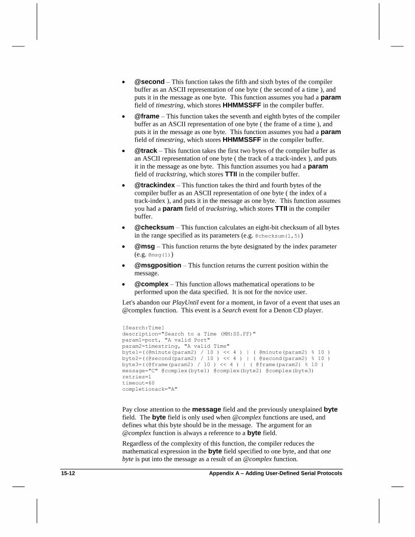
15-12 Appendix A – Adding User-Defined Serial Protocols
@second – This function takes the fifth and sixth bytes of the compiler
buffer as an ASCII representation of one byte ( the second of a time ), and
puts it in the message as one byte. This function assumes you had a param
field of timestring, which stores HHMMSSFF in the compiler buffer.
@frame – This function takes the seventh and eighth bytes of the compiler
buffer as an ASCII representation of one byte ( the frame of a time ), and
puts it in the message as one byte. This function assumes you had a param
field of timestring, which stores HHMMSSFF in the compiler buffer.
@track – This function takes the first two bytes of the compiler buffer as
an ASCII representation of one byte ( the track of a track-index ), and puts
it in the message as one byte. This function assumes you had a param
field of trackstring, which stores TTII in the compiler buffer.
@trackindex – This function takes the third and fourth bytes of the
compiler buffer as an ASCII representation of one byte ( the index of a
track-index ), and puts it in the message as one byte. This function assumes
you had a param field of trackstring, which stores TTII in the compiler
buffer.
@checksum – This function calculates an eight-bit checksum of all bytes
in the range specified as its parameters (e.g. @checksum(1,5))
@msg – This function returns the byte designated by the index parameter
(e.g. @msg(1))
@msgposition – This function returns the current position within the
message.
@complex – This function allows mathematical operations to be
performed upon the data specified. It is not for the novice user.
Let's abandon our PlayUntil event for a moment, in favor of a event that uses an
@complex function. This event is a Search event for a Denon CD player.
[Search:Time]
description="Search to a Time (MM:SS.FF)"
param1=port, "A valid Port"
param2=timestring, "A valid Time"
byte1=((@minute(param2) / 10 ) << 4 ) | ( @minute(param2) % 10 )
byte2=((@second(param2) / 10 ) << 4 ) | ( @second(param2) % 10 )
byte3=((@frame(param2) / 10 ) << 4 ) | ( @frame(param2) % 10 )
message="C" @complex(byte1) @complex(byte2) @complex(byte3)
retries=1
timeout=60
completionack="A"
Pay close attention to the message field and the previously unexplained byte
field. The byte field is only used when @complex functions are used, and
defines what this byte should be in the message. The argument for an
@complex function is always a reference to a byte field.
Regardless of the complexity of this function, the compiler reduces the
mathematical expression in the byte field specified to one byte, and that one
byte is put into the message as a result of an @complex function.

15-13 Appendix A – Adding User-Defined Serial Protocols
Ap
pen
dic
es
A
The Byte field specifies how the byte will be created. There can be up to 20
byte fields. Literal decimal and hex values can be used, as well as functions
that result in a byte or word. The @complex function can not be used.
Currently, 11 operators can be used on the data. They are the following:
Operator Function
+ Add
- Subtract
* Multiply
/ Divide
% Mod (returns remainder from division)
>> Shift Right
<< Shift Left
& Bitwise AND
| Bitwise OR
~ Bitwise NOT
Note Unlike C language or other ways of expressing mathematical algorithms,
there is no operator precedence. Operations are performed from left to right. If
you wish to specify what operand an operator is to work on, use parenthesis to
group the operand.
Let's look at our complex Search:Time event as an example. Here is the
pertinent information:
param2=timestring, "A valid Time"
byte1=((@minute(param2) / 10 ) << 4 ) | ( @minute(param2) % 10 )
byte2=((@second(param2) / 10 ) << 4 ) | ( @second(param2) % 10 )
byte3=((@frame(param2) / 10 ) << 4 ) | ( @frame(param2) % 10 )
message="C" @complex(byte1) @complex(byte2) @complex(byte3)
The Search to a Time event for a Denon player sends the ASCII byte "C"
followed by a BCD ( binary coded decimal ) representation of the minute, then
the second, then the frame to be searched to.
First, the timestring param field takes what the user entered ( let's say
23:12.15 ), and puts 00231215 in the compiler buffer. The message field
directly puts a "C" ( h43 ) into the message, followed by three bytes which are
defined by byte1, byte2, and byte3.
Byte1 takes the third and fourth byte of the compiler buffer, retrieves the
number 23, and puts that into one byte. It then divides that number by 10 and
gets 2. It then shifts left four bits and gets 32 ( h20 ). It then takes that same
minute byte 23, and divides by 10, saving the remainder, not the quotient, which

15-14 Appendix A – Adding User-Defined Serial Protocols
is 3. It then ORs the two results together h20 and h03, to get h23, which is the
binary coded decimal equivalent of 23 decimal.
Byte2 and Byte3 work similarly, except they work on the fifth and sixth bytes,
and the seventh and eighth bytes respectively.
Note The compiler uses a word size for the result of each operation, and then
finally put the LSB byte into the message as the final result. This is to help
produce accurate answers in intermediate stages of math operations.
Byte fields allow for 128 operands and 32 total sets of parenthesis. Not thirty-
two levels deep, but thirty-two total sets.
retries=1
timeout=60
completionack="A"
The Retries field allows for how many times a message will be sent out if the
correct acknowledgment is not received back, specified by the Messageack
and Completionack fields. If the Show Controller receives nothing, or the
incorrect response for a given event, then the Show Controller will try to send
the message again. For example, if retries is 1, the Show Controller will try
one more time to send the event. If the correct response is not received the
second time, the Sequence specified in Configuration | Ports for an Error
Sequence is executed, and the Show Controller does not attempt the event again.
The range for the retries field is 0 to 255. If retries is not specified, the Show
Controller assumes 0 retries, and will start the Error Sequence after the timeout period after the message is sent out the first time.
The Timeout field specifies how long the Show Controller is to wait for an
acknowledge for a message sent out. It is specified in frames. For example, if
timeout is set to 60, the Show Controller will send out the message, and then
wait 60 frames before assuming that there was no response. The timeout should be long enough to allow for both the messageack and the
completionack data to come back in a worst case ( longest ) scenario, is a
normally operating device. The range for the timeout field is 0 to 65535. If
timeout is not specified, the Show Controller assumes 0 timeout, and will
retry or start the Error Sequence immediately after the message is sent out,
without waiting for a response.
The Messageack field specifies what the device should send back to the Show
Controller immediately after receiving the message. This is used to say "Yes I
received what you just sent, and I understood it". Messageack is defined
exactly as the message field, and can use functions, including @complex. If
the messageack field is not specified, the Show Controller assumes there is
no response immediately after the message is sent.
The Completionack field specifies what the device should send back to the
Show Controller when it is finished executing the event it just received. This is
used to say "Ok, the event you requested is completed". Completionack is
defined exactly as the message field, and can use functions, including

15-15 Appendix A – Adding User-Defined Serial Protocols
Ap
pen
dic
es
A
@complex. If the completionack field is not specified, the Show Controller
assumes there is no response after the event is completed.
If the messageack and completionack fields are both not specified, the
Show Controller assumes there is no response whatsoever from the device, and
it ignores both the retries and timeout fields. The message is simply sent out,
and that's it.
Multiple Variations of the Same Event
In many cases the same operation could take several different arguments. For
example, the Search event often has multiple variations, because many devices
support multiple ways of searching. On most DVDs, you can search to a
specific time or a specific frame number. Rather than make two different events,
like SearchTime and SearchFrame, it makes more sense to overlap the two
events. The following two events are an example of this:
[Search:Frame]
param1=port, "A valid Port"
param2=framestring, "A valid Frame number"
message="FR" @string(param2) "SE" h0d
retries=1
timeout=120
completionack="R" h0d
[Search:Time]
param1=port, "A valid Port"
param2=timestring, "A valid Time"
message="TM" @string(param2) "SE" h0d
retries=1
timeout=120
completionack="R" h0d
The compiler will attempt to compiler all variations of the same event before
giving an error. The first event that successfully validates all parameters is used.
Using the above two events, if a user enters a frame number as the second
parameter, the first event validates, and compilation continues. If the user enters
a time as the second parameter, the first event does not validate, but the second
one does, so compilation continues. If the user enters the Date as parameter 2,
both events do not validate, and compilation fails on this event.
Multiple variations can also be used when a event has optional parameters.
[Play:UntilFrame]
param1=port, "A valid Port"
param2=framestring, "A valid Frame number"
message="FR" @string(param2) "PL" h0D
retries=1
timeout=65534
completionack="R" h0d

15-16 Appendix A – Adding User-Defined Serial Protocols
[Play:Continuous]
param1=port, "A valid Port"
message="PL" h0d
retries=1
timeout=60
completionack="R" h0d
In this case, the Play event has an optional parameter, which is the frame to stop
at when reached. If the user enters a frame number as parameter 2, the first
event is compiled. If the user enters nothing as parameter 2, or something that is
not a frame number, the second event will compile, yielding a play forever. If it
is important that the parameter is empty, and not that the user entered invalid
information, this parameter validation could be used in the second event.
param2="", "The PlayContinuous event does not have a parameter 2"
This validation compares what the user entered to an empty string. This forces
the user to leave parameter 2 blank in order to compile.
The important thing to remember with multiple variations of the same event is
that the compiler chooses the first event to pass validation, so you should choose
which variation goes before which variation. In the Play event variations
above, it would not work for the Play:Continuous variation to come first.
This variation would always be chosen, even if the user entered a valid frame
number in parameter 2. This would not be the case if the comparison to an
empty string validation was put into the Play:Continuous variation, but you
should always be careful of the ordering regardless.
Using Variables in your protocol messages
If your show controller has the latest firmware installed you have the ability to
include variable values in your serial messages. Here are some good examples
that show how to implement this feature for a DVM:
[SelectClip:ByNumber]
description=Stops playback and preloads new clip
supported=5.00
retries=1
timeout=60
completionack="R" h0d
param1=port, "A valid Port"
param2=framestring, "A valid clip number (1-99999)"
message=@string(param2) "SE" h0d
[SelectClip:ByVariable]
description=Stops playback and preloads new clip using a variable
supported=6.40
retries=1
timeout=60
completionack="R" h0d

15-17 Appendix A – Adding User-Defined Serial Protocols
Ap
pen
dic
es
A
param1=port, "A valid Port"
param2=var, "A valid variable representing a clip number"
byte1=(@byte(param2) + 1)
message=hF3 @complex(Byte1) "SE" h0d
First you must make sure that the "Supported" field is set to 6.40. WinScript
uses this information to determine whether variables can be sent, and then
compiles the command accordingly. As you can see, the message field in the
Variable version contains an hF3 and a @complex function. The hF3 signifies
that an ASCII representation will be transmitted. There are other modifiers like
hF3 and you can learn how they function in the Built-In Serial Events section.
The @complex function is required since the variable is zero-indexed (starts at 0
rather than 1). Since the show controller expecting a number that is not zero-
indexed, 1 must be added in the previous byte command. Overall, the
[SelectClip:ByVariable] command sends out the same basic result as
[SelectClip:ByNumber], only that data does not have to be hard-coded into your
script. As you can see, this is a very powerful feature as it gives you more
flexibility in your scripts.

15-18 Appendix A – Adding User-Defined Serial Protocols

16-1 Appendix B – Alcorn McBride Serial Control Protocols
Ap
pen
dic
es
B
Appendix B – Alcorn McBride Serial Control Protocols
Any device can serially control an Alcorn McBride Show Controller by using
one of three protocols: Alcorn 9 Bit Control, Alcorn 8 Bit Control, or MIDI.
PCs and other Show Controllers that can support Mark or Space parity over an
RS-232 serial connection can use either Alcorn 8 or 9 Bit Control. Other
devices, such as MIDI based show systems, can use the MIDI protocol.
There are several pluses and minuses to each protocol, but each provides great
flexibility by allowing sequence starts, output activation, and more.
In this section you will find:
Examples of Start Sequence and On/Off Output messages in any of the
three supported Show Control Protocols.
A complete AMI Protocol reference

16-2 Appendix B – Alcorn McBride Serial Control Protocols
The Basics of Alcorn Control Alcorn Control protocols use a very basic message structure consisting of
several similar components: source address, target address, command byte, and
data bytes.
Note This appendix uses the prefix 0x to indicate a hexadecimal number.
Source and Target Address
The Source and Target addresses are derived from the Show Controller’s “Unit
Address” which is a one byte address from 0x00 – 0x79. The source address is
the address of the unit where the message originated. The target address is the
address of the unit that should receive and process the message.
Note The source address of an external device, such as a PC, that is controlling
a Show Controller or group of Show Controllers should be 0xFF.
Command and Data Bytes
A “command opcode” is a term used by programmers to describe a single byte
in a serial message that stands for what is to be done. Alcorn Control messages
can turn on and off Outputs and Flags, start Sequences change Variables, and
even remotely display messages on the LCD Display. Each of these functions
requires a different command.
Some command opcodes require additional “data” bytes that further describe
what is to be done in the Show Controller. These data bytes can take the form of
an Output, Flag, Sequence, Port, or State Variable index; DMX or Analog
values; or a message to display on the LCD or send out a Serial Port. The
following table lists the indices of Show Controller resources:
Resource Index
Output 0x00 – 0x3F
Flag 0x40 – 0x7F
State Variable 0x00 – 0x1F
Serial Port 0x00 – 0x11
Sequence 0x00 – 0xFF
Output or Flag Bank 0x00 – 0x01
Note All resource indices in a Show Controller are zero-based.

16-3 Appendix B – Alcorn McBride Serial Control Protocols
Ap
pen
dic
es
B
The following table lists all Alcorn Control command opcodes (and
corresponding data bytes) that can be used to control resources in an Alcorn
McBride Show Controller.
Note For a full description of each command, see Chapter 6.
Command Op-code
Data Byte 1 Data Byte 2 Data Byte 3 Data Byte 4
Nop 0x01 N/A N/A N/A N/A
On 0x02 <output or flag
index>
N/A N/A N/A
Off 0x03 <output or flag
index>
N/A N/A N/A
Blink 0x04 <output index> <blink period>** N/A N/A
Pulse 0x05 <output index> <pulse duration>** N/A N/A
Toggle 0x06 <output or flag
index>
N/A N/A N/A
AnalogSet 0x07 <analog channel> <value to attain> N/A N/A
DMXSet
(1-256)
0x07 <DMX channel> <value to attain> N/A N/A
DMXRamp
(1-256)
0x08 <DMX channel> <value to attain> <ramp duration,
low byte>***
<ramp duration,
high byte>***
DMXRamp
(1-256)
0x09 <DMX channel> <value to attain> <ramp duration>** N/A
AnalogRamp 0x09 <analog channel> <value to attain> <ramp duration>** N/A
Display 0x0C <message length>* <bytes 1..n to display> N/A N/A
MessageOut 0x0D <serial port index> <message length> <bytes 1..n of message> N/A
SendVar 0x13 <serial port index> <var index> N/A N/A
SendVarEx 0x14 <serial port index> <var index> <formatting>**** N/A
PutVar 0x15 <remote unit address>
<remote var index> <local var index> N/A
Start 0x18 <sequence index> N/A N/A N/A
Stop 0x19 <sequence index> N/A N/A N/A
Pause 0x1A <sequence index> N/A N/A N/A
Reset 0x1B <sequence index> N/A N/A N/A
ShowFlags 0x1C <flag bank index> N/A N/A N/A
DMXSet
(257-512)
0x1D <DMX channel> <value to attain> N/A N/A
DMXRamp
(257-512)
0x1E <DMX channel> <value to attain> <ramp duration, low byte>***
<ramp duration, high byte>***

16-4 Appendix B – Alcorn McBride Serial Control Protocols
Command Op-code
Data Byte 1 Data Byte 2 Data Byte 3 Data Byte 4
DMXRamp
(257-512)
0x1F <DMX channel> <value to attain> <ramp duration>** N/A
Outport 0x20 <output bank index> <value to attain> N/A N/A
SetVarEQ 0x28 <variable index> <value> N/A N/A
AddVar 0x2F <variable index> <value> N/A N/A
SubVar 0x30 <variable index> <value> N/A N/A
SetVarEQ 0x31 <variable index> <variable index> N/A N/A
AddVar 0x38 <variable index> <variable index> N/A N/A
SubVar 0x39 <variable index> <variable index> N/A N/A
ShowVar 0x3A <variable index> N/A N/A N/A
SendVersion 0x42 N/A N/A N/A N/A
DMXSet
(1-256)
0x51 <variable index,
for channel>
<variable index,
for value to attain>
N/A N/A
DMXSet
(257-512)
0x52 <variable index,
for channel>
<variable index,
for value to attain>
N/A N/A
DMXRamp
(1-256)
0x53 <variable index,
for channel>
<variable index,
for value to attain>
<variable index,
for ramp duration>
N/A
DMXRamp
(257-512)
0x54 <variable index,
for channel>
<variable index,
for value to attain>
<variable index,
for ramp duration>
N/A
DMXRamp
(1-256)
0x55 <variable index,
for channel>
<variable index,
for value to attain>
<ramp duration,
low byte>***
<ramp duration,
high byte>***
DMXRamp
(257-512)
0x56 <variable index, for channel>
<variable index, for value to attain>
<ramp duration, low byte>***
<ramp duration, high byte>***
DMXRampSec
(1-256)
0x57 <variable index,
for channel>
<variable index,
for value to attain>
< variable index, for
ramp duration in seconds
N/A
DMXRampSec
(257-512)
0x58 <variable index,
for channel>
<variable index,
for value to attain>
< variable index, for
ramp duration in seconds
N/A
DMXSet
(1-256)
0x59 <DMX channel> <variable index, for value to attain>
N/A N/A
DMXSet
(257-512)
0x5A <DMX channel> <variable index,
for value to attain>
N/A N/A
DMXRamp
(1-256)
0x5B <DMX channel> <variable index,
for value to attain>
<variable index, for
ramp duration>
N/A
DMXRamp
(257-512)
0x5C <DMX channel> <variable index,
for value to attain>
<variable index,
for ramp duration>
N/A
DMXRamp
(1-256)
0x5D <DMX channel> <variable index,
for value to attain>
<ramp duration,
low byte>***
<ramp duration,
high byte>***

16-5 Appendix B – Alcorn McBride Serial Control Protocols
Ap
pen
dic
es
B
Command Op-code
Data Byte 1 Data Byte 2 Data Byte 3 Data Byte 4
DMXRamp
(257-512)
0x5E <DMX channel> <variable index,
for value to attain>
<ramp duration,
low byte>***
<ramp duration,
high byte>***
DMXRampSec
(1-256)
0x5F <DMX channel> <variable index,
for value to attain>
< variable index,
for ramp duration, in seconds
N/A
DMXRampSec
(257-512)
0x61 <DMX channel> <variable index, for value to attain>
< variable index,
for ramp duration,
in seconds
N/A
* In Bytes (0x00-0xFF)
** In Frames (0x00-0xFF)
*** In Frames (0x0000-0xFFFF)
**** Byte takes the following form:
Bits Definition
7 and 6 Not Used
5, 4, and 3 Text Formatting Code:
000 – Send only significant characters (“7”)
001 – Send leading zeros (“007”)
010 – Send leading spaces (“ 7”)
011 – Send trailing spaces (“7 ”)
2, 1, and 0 Numerical Type Code:
000 – ASCII Decimal (“000” thru “255”)
001 – ASCII Hexadecimal (“00” thru “FF”)
010 – ASCII Octal (“000 thru “377”)
011 – Straight binary
Alcorn 9 Bit Control Advantage: Bullet-proof messaging
Disadvantage: Difficult to program
Resources: C++ Programming Library available free to developers.
Alcorn 9 Bit Control uses Mark and Space parity bits to create a start of message
and end of message delimiter. When Mark parity is used, we say that the byte
has its ninth bit set. When Space parity is used, we say that the byte does not
have its ninth bit set.
Note An asterisk (*) indicates that a byte has its ninth bit set (Mark Parity), and
two asterisks (**) indicate that a byte has both the eighth and ninth bits set.

16-6 Appendix B – Alcorn McBride Serial Control Protocols
The Show Controller sends a response byte of 0xAA to indicate that it received
a valid command or 0x55 to indicate that it received an invalid command.
Here is the general form of an Alcorn 9 Bit Control message:
<source address>** <target address> <command opcode> <data bytes 1..n> <checksum>*
The <checksum> byte is the 8-bit sum of all previous bytes in the message
shifted right once. For example, if the sum of all bytes in the message is 0x5D
(or 01011101 in binary), shifting it right once will produce 0x2E (or 00101110
in binary). This byte is used for error detection and will cause the entire
message to be ignored if it is incorrect.
Here is an example Start Sequence #2 message sent from a PC (address 0xFF) to
a Show Controller whose address is 0x00:
0xFF* 0x00 0x18 0x01 0x0C*
Alcorn 8 Bit Control Advantage: Easy to program
Disadvantage: Not bullet-proof
Resources: C++ Programming Library available free to developers.
Alcorn 8 Bit Control uses the byte 0xF5 as a start of message delimiter. There is
no Mark or Space parity and any byte could have bit eight set high or low.
Here is the general form of an Alcorn 8 Bit Control message:
0xF5 <target address> <response> <length> <command opcode> <data bytes 1..n> <checksum>
The <response> byte tells the Show Controller what kind of response to send
back to the originating device. The response byte can take the following forms:
0x00 – Send no response back to the sender.
0x01 – Send a 0xAA (ACK) or 0x55 (NACK).
0x02 – Send the entire message back to the sender followed by an ACK or
NACK.
The <length> byte tells the Show Controller how many command and data
bytes are in the message.
The <checksum> byte is the 8-bit sum of all previous bytes in the message
(except the 0xF5).
Here is an example Start Sequence #2 message (no response) sent from a PC
(address 0xFF) to a Show Controller whose address is 0x00:
0xF5 0x00 0x00 0x02 0x18 0x01 0x1B
Note: Alcorn 8-bit control cannot be operated at a baud rate greater than 19,200
baud.

16-7 Appendix B – Alcorn McBride Serial Control Protocols
Ap
pen
dic
es
B
MIDI Control Advantage: Supported by most MIDI devices
Disadvantage: Not bullet-proof
Alcorn McBride Show Controllers with a MIDI IN port can also be controlled
by the MIDI Control messages SYSEX, NOTE ON, and NOTE OFF.
Start a Sequence with SYSEX “GO CUE”
The SYSEX “GO CUE” message can be used to start a sequence. Here is the
general form:
0xF0 0x7F <target address> 0x02 0x7F 0x01 <data #1> <data #2> <data #3> 0xF7
The <data #1> byte is the ASCII hundreds digit of the sequence number
(sequence index + 1). For example, if you were starting sequence #104, the
<data #1> byte is 0x31 (or “1”).
The <data #2> byte is the ASCII tens digit of the sequence number (sequence
index + 1). For example, if you were starting sequence #104, the <data #2>
byte is 0x30 (or “0”).
The <data #3> byte is the ASCII ones digit of the sequence number (sequence
index + 1). For example, if you were starting sequence #104, the <data #3>
byte is 0x34 (or “4”).
Here is an example Start Sequence #4 message sent from an Amiga (address
0xFF) to a Show Controller whose address is 0x00:
0xF0 0x7F 0x00 0x02 0x7F 0x01 0x30 0x30 0x34 0xF7
Set a State Variable with SYSEX “SET”
The SYSEX “SET” message can be used to set the value of a State Variable.
Here is the general form:
0xF0 0x7F <target address> 0x02 0x7F 0x06 <data #1> 0x00 <data #2> <data #3> 0xF7
The <data #1> byte is the state variable index number. For example, if you
were setting variable #3, the <data #1> byte would be 0x03.
The <data #2> byte represents bits 0-6 of the desired value. For example, if the
desired value were 0x8E, <data #2> would be 0x0E.
The <data #3> byte represents the MSB (or bit 7) of the desired value. For
example, if the desired value were 0x8E, <data #3> would be 0x01.
Here is an example “Set Var #3 to 8E” message sent from an Amiga (address
0xFF) to a Show Controller whose address is 0x00:
0xF0 0x7F 0x00 0x02 0x7F 0x06 0x03 0x00 0x0E 0x01 0xF7

16-8 Appendix B – Alcorn McBride Serial Control Protocols
Turn on an Output with NOTE ON
The NOTE ON message can be used to turn on an output:
<target address + 0x90> <output index + 0x3C> 0x40
Here is an example “On Output #1” message sent from an Amiga (address
0xFF) to a Show Controller whose address is 0x00:
0x90 0x3C 0x40
Turn off an Output with NOTE OFF
The NOTE OFF message can be used to turn off an output:
<target address + 0x80> <output index + 0x3C> 0x40
Here is an example “Off Output #5” message sent from an Amiga (address
0xFF) to a Show Controller whose address is 0x00:
0x80 0x3C 0x40

17-1 Appendix C – Cable Reference
Ap
pen
dic
es
C
Appendix C – Cable Reference
Common Show Control Cable Pinouts This appendix gives the pinouts for many common show control cables. You
can make these cables yourself, or you may purchase them from Alcorn
McBride by contacting our Sales Department at (407) 296-5800.
Programming Cable
DB9F #1 Pin DB9F #2 Pin
2 2
3 3
5 (shield) 5 (shield)
Also used to connect a master controller’s serial port to a slave’s programming port.
Show Control I/O Expansion (Null Modem)
DB9F #1 Pin DB9F #2 Pin
2 3
3 2
5 (shield) 5 (shield)
Used to interconnect two serial ports.


Appendix D – Available Accessories 18-1
Ap
pen
dic
es
D
Appendix D – Available Accessories
Components The following table lists commonly used Alcorn McBride Show Controller
accessories, their manufacturers’ part numbers, and our stock number. All parts
are available from Alcorn McBride by next day FedEx shipment.
Part Description Mfg Part No. Stock No.
DB37 Female, Solder Cup Amp 747917-2 642-000166
DB37 Male, Solder Cup Amp 747916-2 642-000151
DB37 Housing Assembly Amp 748676-4 642-000631
DB9 Female, Solder Cup Amp 747905-2 642-000167
DB9 Male, Solder Cup Amp 747904-2 642-000168
DB9 Housing Assembly Amp 748676-1 642-000630
5 Pin DIN (MIDI) Connector, Male Switchcraft 05GM5M 643-000632
BNC (Sync) Connector (RG-59 coax) Amp 413589-2/3 641-000628
1488 RS-232 Driver National DS1488AN 720-000364
1489 RS-232 Receiver National DS1489AN 720-000356
75174 RS-422 Driver TI SN75174N 720-000359
75175 RS-422 Receiver TI SN75175N 720-000360
DIP Resistor, 16 Pin Discrete, 180 Ohm Bourns 4116R-001-181 635-000126
DIP Resistor, 16 Pin Discrete, 1.5K Bourns 4116R-001-152 635-000125
DIP Resistor, 16 Pin Discrete, 10K Bourns 4116R-001-103 635-000625
SIP Resistor, 10 Pin Discrete, 220 Ohm Bourns 4610X-002-221 634-000624
EEPROM, Show Memory, 32K Atmel AT28C256-20PC 731-000374
Alcorn McBride Field Kit 1
An assortment of the above, plus spare
screws, labels, markers, and a screwdriver, all in a carrying case.
Alcorn 230-100435

18-2 Appendix D – Available Accessories
Manufactured Cables The following table lists commonly used Alcorn McBride Show Controller
cables. All cables are available from Alcorn McBride by next day Fedex
shipment.
Part Description Stock Number
Cable, DB9F/DB9F, Program, 10 foot 699-000288
Cable, DB9F/DB9F, Program, 25 foot 699-000294
Cable, DB9F/DB9F, Null Modem, 2 foot 699-000295
Cable, Pioneer/Panasonic, 10 foot 699-000286
Cable, Pioneer/Panasonic, 25 foot 699-000293
Cable, Sony, 10 foot 699-000287
Cable, Sony, 25 foot 699-000292

Appendix D – Available Accessories 18-3
Ap
pen
dic
es
D
Third Party Equipment
Serial Countdown Clocks
Applied Technical Systems manufactures a line of serially-controlled
countdown clocks that are useful for preshows and queue lines.
Applied Technical Systems Contact: Jim Reccelli Tel: (800) 444-7161 Fax: (318) 631-7613
Real Time Clocks
Sometimes it is desirable to trigger a show or activity at a preset time of day.
ESE makes several Real Time Clock modules that may be connected directly to
Alcorn McBride Show Controllers using a serial cable. Their models ES-225
and 194A are a frequently used combination.
ESE Web: www.ese-web.com Tel: (310) 322-2136 Fax: (310) 322-8127
Chrontrol makes Real Time Clocks used to automate radio stations using contact
closure outputs.
Chrontrol Corp Contact: Jim Durham Tel: (619) 566-5656 Fax: (619) 566-0140

18-4 Appendix D – Available Accessories

Index 1
Index
A Accessories .......................................................................................................................................................... 18-1 Alcorn 8 Bit Control ...................................................................................................................................... 16-1, 16-6 Alcorn 9 Bit Control .....................................................................................................6-16, 6-17, 7-9, 15-7, 16-1, 16-5
B Buttons
DMX Machine ................................................................................................................................................... 13-5 SMPTE Machine ............................................................................................................................................... 14-7 V16+ ................................................................................................................................................................. 8-10
C Cable Pinouts ....................................................................................................................................................... 17-1 cables .......................................................................................................................................................... 17-1, 18-2 Chasing Timecode
Dropout Tolerance ............................................................................................................................................ 4-26 Jam Sync Mode ................................................................................................................................................ 4-27 Reset Mode ...................................................................................................................................................... 4-27
Communication Options ........................................................................................................................................ 4-41 Compiler Options .................................................................................................................................................. 4-40 Contact Closures
IO64 .................................................................................................................................................................. 12-2 SMPTE Machine ...................................................................................................................................... 14-7–14-8 V16+ ............................................................................................................................................ 8-2, 8-6–8-8, 8-10 V2+ .......................................................................................................................................................... 10-5–10-6
D Digital Video Machine ..........................................................................................5-2, 5-29, 5-30, 5-35, 7-1, 7-18, 7-19 dimmer
DMX Machine ................................................................................................................................................... 13-4 diode
IO64 .................................................................................................................................................................. 12-9 SMPTE Machine ................................................................................................................................... 14-11, 14-13 V16+ ................................................................................................................................................................. 8-13 V2+ .........................................................................................................................................................10-9, 10-11
DMX 5-2, 5-17, 5-21, 6-23, 16-2, 16-3, 16-4, 16-5 DMX Machine ................................................................................................................................................ 2-4, 12-1
E EBU 2-4 EEPROM

19-2 Index
Accessories ....................................................................................................................................................... 18-1 DMX Machine .................................................................................................................................................... 13-2 IO64 .................................................................................................................................................................. 12-2 SMPTE Machine ................................................................................................................................................ 14-2 V16+ ...........................................................................................................................................................8-2, 8-16 V2+ .................................................................................................................................................................... 10-2
Environment DMX Machine .................................................................................................................................................... 13-2 IO64 .................................................................................................................................................................. 12-2 SMPTE Machine ................................................................................................................................................ 14-2 V16+ ....................................................................................................................................................................8-2 V2+ .................................................................................................................................................................... 10-2
Event Editing Copying, Cutting, and Pasting Events ................................................................................................................ 4-21 Data Fields ........................................................................................................................................................ 4-22 Event Parameters .............................................................................................................................................. 4-24 Event Wizard .......................................................................................................... 4-5, 4-22, 4-23, 4-39, 5-35, 15-5 Inserting and Deleting Events ............................................................................................................................ 4-21 Label....................................................................................................................................... 4-22, 5-11, 7-17, 15-7 Time ................................................................................................................................... 4-22, 4-38, 15-12, 15-13
Events AddVar ..................................................................................................................... 5-7, 5-8, 5-13, 6-12, 6-25, 16-4 Blink ............................................................................................................................................ 4-3, 5-4, 5-5, 16-3 Break ................................................................................................................................................................. 5-21 ChasePlay ......................................................................................................................................................... 5-27 ClearCue ........................................................................................................................................................... 5-28 ControlChange................................................................................................................................................... 5-22 DisableSMPTE ................................................................................................................................ 4-13, 5-23, 5-24 Display ............................................................................................................. 4-8, 5-14, 5-15, 6-4, 6-13, 6-17, 16-3 DMXRamp ..................................................................................................................... 5-17, 5-21, 6-24, 16-3, 16-4 EnableSMPTE ................................................................................................................................. 4-13, 5-23, 5-24 External Events............................................................................................................................................ 5-2, 5-3 FeedThrough ..................................................................................................................................................... 5-27 Goto .............................................................................. 5-2, 5-9, 5-10, 6-4, 6-12, 6-13, 6-14, 6-15, 6-16, 6-17, 6-23 IfOff .....................................................................................................................5-2, 5-9, 5-11, 6-4, 6-7, 6-18, 6-23 IfOn ................................................................................................................................... 5-2, 5-9, 5-11, 5-12, 6-23 IfVarEQ ................................................................................................... 5-2, 5-9, 5-11, 5-12, 5-13, 6-13, 6-15, 6-16 IfVarGE .............................................................................................................................. 5-2, 5-9, 5-12, 5-13, 6-16 IfVarGT .......................................................................................................................................5-2, 5-9, 5-12, 6-16 IfVarLE ..................................................................................................................... 5-2, 5-9, 5-12, 5-13, 6-12, 6-13 IfVarLT ........................................................................................................................................5-2, 5-9, 5-12, 6-16 IfVarNE ................................................................................................................................................5-2, 5-9, 5-12 InPort ...................................................................................................................................................................5-6 Internal Events .....................................................................................................................................................5-2 MessageOut ........................................................................................................... 4-9, 5-17, 5-18, 5-19, 15-4, 16-3 MessageOutVar ................................................................................................................................................. 5-18 Mute ................................................................................................................................................ 5-31, 5-33, 15-4 Nop ................................... 4-22, 5-2, 5-9, 5-11, 5-12, 5-13, 6-8, 6-12, 6-13, 6-15, 6-16, 6-17, 6-18, 6-23, 7-15, 16-3 NoteOn .............................................................................................................................................................. 5-22 Off ..................................................................................................................................... 5-4, 5-7, 6-16, 6-17, 16-3 On ..............................................................................................................................5-3, 5-4, 5-7, 6-21, 6-23, 16-3 OutPort ........................................................................................................................................ 5-4, 5-5, 5-6, 16-4 Pause ..................................................................................................... 5-9, 5-10, 5-31, 5-32, 6-8, 7-11, 7-17, 16-3 PauseSMPTE ........................................................................................................................................... 5-23, 5-24 PileOn ................................................................................................................................................................ 5-27 PileOnAndLoop.................................................................................................................................................. 5-28 Play ........................................... 5-12, 5-13, 5-25, 5-26, 5-29, 5-30, 5-31, 5-32, 6-6, 6-7, 6-9, 6-11, 6-14, 6-19, 15-4 PlayAndLoop ................................................................................................................. 5-25, 5-29, 5-30, 5-31, 5-32 PlayUntil ................................................................................................................................................. 15-9, 15-12 Program Control Events ............................................................................................................................... 5-2, 5-9 ProgramChange ................................................................................................................................................ 5-22 Pulse ..........................................................................................................................4-3, 5-4, 5-5, 6-18, 6-19, 16-3

Index 3
PutVar .............................................................................................................................................5-17, 5-20, 16-3 Record .............................................................................................................................................................. 5-26 RecoverLCD ....................................................................................................................................3-22, 5-14, 5-15 Reset ......................................................................................................................5-9, 5-10, 5-28, 6-12, 6-13, 16-3 RestoreVar ......................................................................................................................................................... 5-8 SaveVar .............................................................................................................................................................. 5-8 Search .............................................................. 6-5, 6-6, 6-7, 6-9, 6-10, 6-11, 6-14, 6-19, 15-4, 15-12, 15-13, 15-15 SelectClip ................................................................................................................................................ 5-25, 5-29 SelectCue ......................................................................................................................................................... 5-25 SelectDrive ....................................................................................................................................................... 5-29 SendAsciiDec ..................................................................................................................................5-17, 5-19, 5-20 SendAsciiHex ..................................................................................................................................5-17, 5-19, 5-20 SendAsciiOct ........................................................................................................................................... 5-17, 5-19 SendVar ...........................................................................................................................................5-17, 5-20, 16-3 SetSMPTETime ....................................................................................................................................... 4-12, 5-23 SetVarEQ ........................................................................................................5-7, 5-8, 5-13, 6-12, 6-13, 6-25, 16-4 ShowFlags .......................................................................................................................................5-14, 5-16, 16-3 ShowVar ...................................................................................................... 5-11, 5-13, 5-14, 5-16, 5-19, 5-20, 16-4 SMPTE Events ................................................................................................................................................. 5-23 Spindown .......................................................................................................................................................... 15-4 Spinup .............................................................................................................................................................. 15-4 SPlay ....................................................................................................................................................... 5-31, 5-33 SPlayAndLoop ......................................................................................................................................... 5-31, 5-34 Start .................................................................... 5-9, 5-10, 6-4, 6-5, 6-6, 6-7, 6-8, 6-9, 6-10, 6-15, 6-21, 6-23, 16-3 Still ................................................................................................................................. 5-25, 5-28, 5-29, 5-30, 15-4 Still ...................................................................................................................................................................... 6-3 Stop ........................................................................................................................4-19, 5-9, 5-10, 6-11, 6-14, 16-3 StoreLCD ................................................................................................................................3-21, 3-22, 5-14, 5-15 SubVar.............................................................................................................................. 5-7, 5-8, 6-12, 6-13, 16-4 Toggle ................................................................................................................................................ 5-4, 5-7, 16-3 UnMute .................................................................................................................................................... 5-31, 5-33
F Firmware
DMX Machine ................................................................................................................................................... 13-7 IO64 ................................................................................................................................................................ 12-10 SMPTE Machine ............................................................................................................................................. 14-15 V16+ ................................................................................................................................................................. 8-16 V2+ ................................................................................................................................................................. 10-12
Flags ....................................................................................................3-10, 4-4, 5-7, 5-14, 5-16, 6-7, 15-6, 15-7, 16-2 Front Panel
DMX Machine .......................................................................................................................................... 13-2, 13-5 IO64 .................................................................................................................................................................. 12-2 SMPTE Machine ...................................................................................................................................... 14-2, 14-7 V16+ .......................................................................................................................................................... 8-2, 8-10 V2+ .......................................................................................................................................................... 10-2, 10-5
fuses IO64 ......................................................................................................................................................... 12-2, 12-8 V16+ .......................................................................................................................................................... 8-2, 8-11
I indicator lamp
IO64 .................................................................................................................................................................. 12-8 SMPTE Machine ............................................................................................................................................. 14-12 V16+ ................................................................................................................................................................. 8-12 V2+ ................................................................................................................................................................. 10-10
inductive load IO64 ......................................................................................................................................................... 12-8–12-9 SMPTE Machine ................................................................................................................................... 14-12–14-13

19-4 Index
V16+ ......................................................................................................................................................... 8-12–8-13 V2+ ....................................................................................................................................................... 10-10–10-11
Inputs ...............................................................................3-9, 4-3, 4-4, 6-22, 7-2, 7-3, 7-4, 7-7, 7-12, 7-27, 7-28, 15-6 IO64 2-4, 12-1
L LCD contrast
SMPTE Machine ................................................................................................................................................ 14-6 V16+ ....................................................................................................................................................................8-5 V2+ .................................................................................................................................................................... 10-4
LCD Display......................................................................................... 4-6, 5-1, 5-2, 5-14, 5-16, 7-10, 7-15, 7-17, 16-2 SMPTE Machine ....................................................................................................................................... 14-2, 14-6 V16+ ............................................................................................................................................................ 8-2, 8-5 V2+ ........................................................................................................................................................... 10-2, 10-4
LED IO64 .................................................................................................................................................................. 12-2 SMPTE Machine ................................................................................................................................................ 14-2 V16+ ....................................................................................................................................................................8-2 V2+ .................................................................................................................................................................... 10-2
M MIDI 4-3, 4-11, 5-2, 5-22, 8-2, 8-3, 8-5, 8-15, 10-2–10-4, 12-2–12-5, 12-10, 14-2–14-4, 15-3, 16-1, 16-7, 18-1
N NTSC
SMPTE Machine ..................................................................................................................................... 14-2, 14-14 V16+ ...........................................................................................................................................................8-2, 8-14 V2+ .................................................................................................................................................................... 10-2
Null Modem ........................................................................................................................................................... 17-1 cables ................................................................................................................................................................ 18-2
O Opto Inputs
DMX Machine .................................................................................................................................................... 13-2 IO64 .................................................................................................................................................................. 12-2 SMPTE Machine ................................................................................................................................................ 14-2 V16+ ....................................................................................................................................................................8-2 V2+ .................................................................................................................................................................... 10-2
Outputs .............................................................. 4-3, 4-4, 5-4, 5-6, 7-2, 7-3, 7-4, 7-6, 7-8, 7-12, 7-13, 7-28, 15-6, 16-2
P PAL
SMPTE Machine ..................................................................................................................................... 14-2, 14-14 V16+ ...........................................................................................................................................................8-2, 8-14 V2+ .................................................................................................................................................................... 10-2
Panasonic cables ................................................................................................................................................................ 18-2
Pioneer cables ................................................................................................................................................................ 18-2
Power DMX Machine .................................................................................................................................................... 13-2 IO64 .................................................................................................................................................................. 12-2 SMPTE Machine ................................................................................................................................................ 14-2 V16+ ....................................................................................................................................................................8-2 V2+ .................................................................................................................................................................... 10-2

Index 5
Power Supply DMX Machine ................................................................................................................................................... 13-7 IO64 ................................................................................................................................................................ 12-10 SMPTE Machine ............................................................................................................................................. 14-15 V16+ ................................................................................................................................................................. 8-15 V2+ ................................................................................................................................................................. 10-12
Program Counter .................................................................................................................................................... 6-2 Programmer Port
DMX Machine ................................................................................................................................................... 13-3 IO64 .................................................................................................................................................................. 12-3 SMPTE Machine ............................................................................................................................................... 14-3 V16+ ................................................................................................................................................................... 8-3 V2+ ................................................................................................................................................................... 10-3
Programming Cable .............................................................................................................................................. 17-1 Protocol Files
@byte ................................................................................................................................................... 15-10, 15-11 @checksum .................................................................................................................................................... 15-12 @complex ....................................................................................................................... 15-12, 15-13, 15-14, 15-15 @decstring ..................................................................................................................................................... 15-11 @frame ................................................................................................................................................. 15-12, 15-13 @hextring ....................................................................................................................................................... 15-11 @hour ............................................................................................................................................................. 15-11 @index ........................................................................................................................................................... 15-11 @length .......................................................................................................................................................... 15-11 @minute .................................................................................................................................... 15-11, 15-12, 15-13 @msg ............................................................................................................................................................. 15-12 @msgposition ................................................................................................................................................. 15-12 @second .............................................................................................................................................. 15-12, 15-13 @string ............................................................................................................................. 15-4, 15-10, 15-11, 15-15 @track ............................................................................................................................................................ 15-12 @trackindex .................................................................................................................................................... 15-12 @word ............................................................................................................................................................ 15-11 Author ............................................................................................................................................................... 15-2 BaudRate ................................................................................................................................................. 15-2, 15-3 byte .................................................................................. 15-6, 15-7, 15-8, 15-9, 15-10, 15-11, 15-12, 15-13, 15-14 bytelabel .................................................................................................................................................. 15-6, 15-7 bytetime ................................................................................................................................................... 15-6, 15-7 Completionack ....................................................................................................... 15-4, 15-12, 15-14, 15-15, 15-16 contains ...........................................................................................................................................15-6, 15-8, 15-9 DataBits ................................................................................................................................................... 15-2, 15-3 datastring .........................................................................................................................................15-4, 15-6, 15-8 flag ...................................................................................................................................................15-6, 15-7, 15-9 framestring ................................................................................................................... 15-4, 15-5, 15-6, 15-8, 15-15 input .................................................................................................................................................................. 15-6 lcdstring ................................................................................................................................................... 15-6, 15-8 Maker ............................................................................................................................................................... 15-2 Message field ................................................................................................ 15-6, 15-9, 15-10, 15-12, 15-13, 15-14 messageack.......................................................................................................................................... 15-14, 15-15 output ...................................................................................................................................................... 15-6, 15-9 param field .................................................................................................... 15-6, 15-8, 15-10, 15-11, 15-12, 15-13 Parity ....................................................................................................................................................... 15-2, 15-3 port ............................................................................................... 15-4, 15-5, 15-6, 15-7, 15-9, 15-12, 15-15, 15-16 porttyperemote ......................................................................................................................................... 15-6, 15-7 Protocol Editor .................................................................................................................................................. 5-35 Protocol Viewer ................................................................................................................................................... 4-1 remoteflag ......................................................................................................................................................... 15-7 remoteinput ....................................................................................................................................................... 15-6 remoteoutput..................................................................................................................................................... 15-6 remoteport ........................................................................................................................................................ 15-7 remotesequence ............................................................................................................................................... 15-7 remotevar ......................................................................................................................................................... 15-7 sequence ....................................................................................................................................... 15-6, 15-7, 15-14

19-6 Index
StopBits .................................................................................................................................................... 15-2, 15-3 string....................................................................................................................................... 15-6, 15-7, 15-8, 15-9 Supported ............................................................................................................................... 15-2, 15-3, 15-4, 15-5 timestring ........................................................................................... 15-6, 15-8, 15-10, 15-11, 15-12, 15-13, 15-15 trackstring ...................................................................................................................................... 15-6, 15-8, 15-12 var ..................................................................................................................................................................... 15-6 Version .............................................................................................................................................................. 15-2 word ............................................................................................................................................ 15-7, 15-11, 15-13
R Rear Panel
DMX Machine .................................................................................................................................. 13-2–13-3, 13-5 IO64 ....................................................................................................................................... 12-1–12-3, 12-5–12-6 SMPTE Machine .............................................................................................................................. 14-2–14-3, 14-7 V16+ ............................................................................................................................................ 8-2–8-3, 8-6, 8-14 V2+ .................................................................................................................................................. 10-2–10-3, 10-5
relay coil SMPTE Machine .............................................................................................................................................. 14-13 V16+ .................................................................................................................................................................. 8-13 V2+ .................................................................................................................................................................. 10-11
Relay Outputs IO64 ......................................................................................................................................................... 12-2, 12-8 V16+ ...........................................................................................................................................................8-2, 8-11
REMed Events ....................................................................................................................................................... 4-22 RS-232 ...........................................................................................................................................................7-3, 16-1 RS-422
Accessories ....................................................................................................................................................... 18-1 IO64 ......................................................................................................................................................... 12-2–12-4 V16+ ....................................................................................................................................................................8-3
RS-485 ....................................................................................................................................................................4-3 DMX Machine .................................................................................................................................................... 13-4 IO64 ......................................................................................................................................................... 12-3–12-4 V16+ ..................................................................................................................................................... 8-2, 8-3–8-4
S Script Wizard ..................................................................................................................................................4-1, 4-36 Scripts
Chasing Timecode ............................................................................................................................................. 4-26 Compiling................................................................................................................................ 3-22, 4-28, 4-40, 15-9 Downloading ........................................................................................................................... 3-22, 4-28, 4-29, 4-31 Port Configuration ................................................................................................................................................4-5 Sequences................................................................................................................ 3-16, 3-18, 4-14, 4-20, 5-9, 6-3 Unit Address ...............................................................................................................................4-3, 7-7, 16-2, 16-3 Unit Type .............................................................................................................................................4-3, 4-36, 7-7
Sequence Editing Copying, Cutting, and Pasting Sequences ......................................................................................................... 4-15 Indentation ......................................................................................................................................................... 4-16 Index Number ........................................................................................................... 4-6, 4-7, 4-14, 4-20, 4-21, 5-16 Inserting and Deleting Sequences ..................................................................................................................... 4-15 Looping Enabled/Disabled ................................................................................................................................. 4-17 Pause Trigger .................................................................................................................................................... 4-20 Reset Trigger ..................................................................................................................................................... 4-20 Restart Enabled/Disabled .................................................................................................................................. 4-17 Restart Lockout................................................................................................................................ 3-18, 4-17, 6-21 Start Trigger ............................................................. 3-17, 4-18, 4-20, 6-15, 6-16, 6-17, 6-19, 6-22, 6-25, 7-11, 7-15 Stop Trigger ....................................................................................................................................................... 4-19 Timecode Trigger/Chase ................................................................................................................................... 4-17
Serial Ports .......................................................................................3-11, 4-3, 5-1, 5-17, 7-2, 7-9, 7-11, 8-1–8-2, 17-1 DMX Machine .................................................................................................................................................... 13-3

Index 7
IO64 .................................................................................................................................................................. 12-3 SMPTE Machine ...................................................................................................................................... 14-2–14-3 V16+ ............................................................................................................................................................ 8-3–8-4 V2+ .......................................................................................................................................................... 10-2–10-3
Show Memory .................................................................................................................................................. 8-1–8-2 Accessories ...................................................................................................................................................... 18-1 DMX Machine ................................................................................................................................................... 13-2 IO64 .................................................................................................................................................................. 12-2 V16+ ................................................................................................................................................................. 8-16 V2+ ................................................................................................................................................................... 10-2
Size and Weight IO64 .................................................................................................................................................................. 12-2 SMPTE Machine ............................................................................................................................................... 14-2 V16+ ................................................................................................................................................................... 8-2 V2+ ................................................................................................................................................................... 10-2
SMPTE ................................. 4-1, 4-11, 4-12, 4-16, 4-17, 4-29, 4-31, 4-38, 5-2, 5-23, 5-24, 5-31, 5-33, 5-34, 5-35, 7-6 Frame Rate ....................................................................................................................................................... 4-10 Generate/Read Options .................................................................................................................................... 4-10 Generation .......................................................................................................................4-11, 4-13, 5-2, 5-23, 5-24 Triggering .......................................................................................................................................................... 4-9
SMPTE Machine ................................ 2-4, 4-1, 4-9, 4-10, 4-11, 4-12, 4-17, 4-29, 4-31, 4-32, 5-2, 5-23, 7-6, 13-1, 14-1 snubber
IO64 .................................................................................................................................................................. 12-9 SMPTE Machine ................................................................................................................................... 14-11, 14-13 V16+ ................................................................................................................................................................. 8-13 V2+ .........................................................................................................................................................10-9, 10-11
solenoid IO64 .................................................................................................................................................................. 12-9 SMPTE Machine ............................................................................................................................................. 14-13 V16+ ................................................................................................................................................................. 8-13 V2+ ................................................................................................................................................................. 10-11
Sony cables ............................................................................................................................................................... 18-2
Sync Termination SMPTE Machine ............................................................................................................................................. 14-14 V16+ ................................................................................................................................................................. 8-14
T Technical Support
E-Mail ................................................................................................................................................................. 1-3 Software/Firmware Updates ................................................................................................................................ 1-3 Telephone ........................................................................................................................................................... 1-3
terminating resistor DMX Machine ................................................................................................................................................... 13-4 SMPTE Machine ............................................................................................................................................. 14-14 V16+ ................................................................................................................................................................. 8-14
terminator ........................................................................................................................................................... 14-14 V16+ .......................................................................................................................................................... 8-4, 8-14
Time Calculator .............................................................................................................................................. 4-1, 4-38 Time Counter .......................................................................................................................................................... 6-2 Timecode .............................................................................................................................................................. 4-17
U User-Defined Tools ............................................................................................................................................... 4-42
V video sync
SMPTE Machine .....................................................................................................................................14-6, 14-14

19-8 Index
V16+ .................................................................................................................................................................. 8-14 Video Sync .....................................................................................................................................................5-33, 7-5 Voltage Inputs
SMPTE Machine ....................................................................................................................................... 14-7–14-9 V16+ ............................................................................................................................................................ 8-6–8-8 V2+ ........................................................................................................................................................... 10-5–10-7
W Weight ................................................................................................................................. 8-2, 10-2, 12-2, 13-2, 14-2 WinScript .................................................................................................................................................................1-2