
Short circuiting a battery demo… Dangerous ? High current?
17
Internal Resistance, r Short circuiting a battery demo… Dangerous ? High current?
-
Upload
cody-mcdowell -
Category
Documents
-
view
235 -
download
2
Transcript of Short circuiting a battery demo… Dangerous ? High current?
Internal Resistance, r
Short circuiting a battery demo…
Dangerous ?
High current?


The internal resistance of a battery is dependent on the specific battery's size, chemical properties, age, temperature
and the discharge current
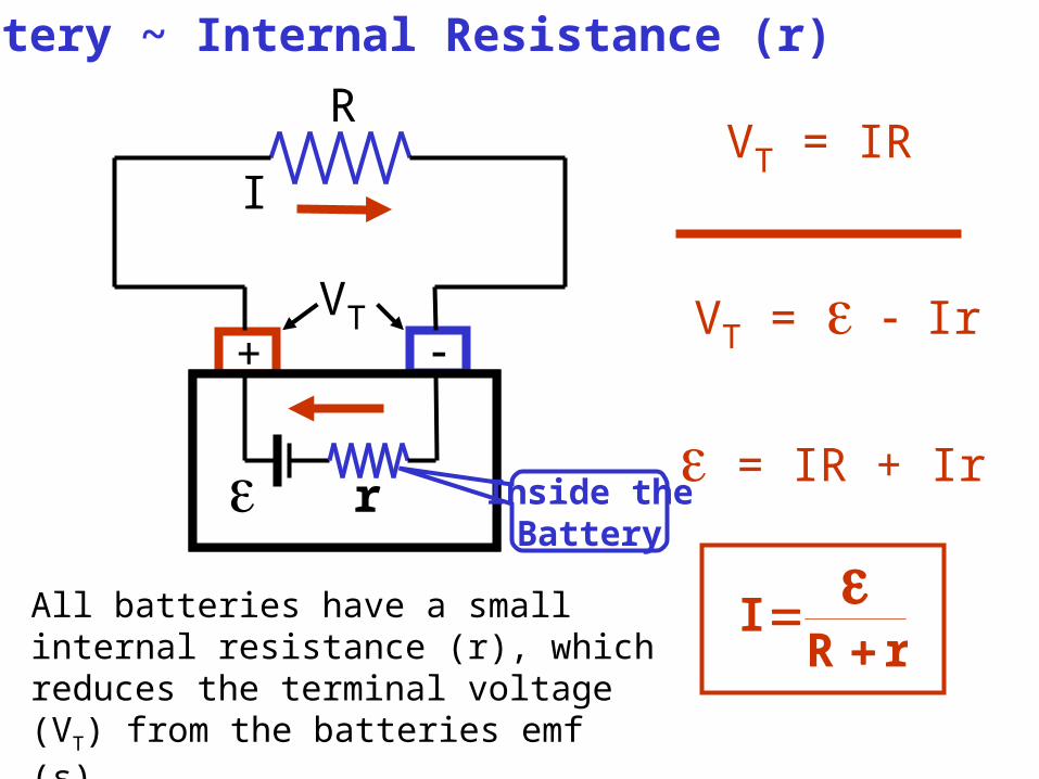
Battery ~ Internal Resistance (r)
+ -
R
VT
e r
VT = IR
VT = e - Ir
e = IR + Ir
rRI
I
Inside theBattery
All batteries have a small internal resistance (r), which reduces the terminal voltage (VT) from the batteries emf (ε).

• Terminal voltage (VT or Vab) is the voltage a battery delivered to the circuit. Define as the voltage between the battery terminals.
• Electromotive force (emf, ε) is the voltage produced by the chemical reaction of the battery.
• When no current is drawn from the battery, the terminal voltage is equal to the emf ε. IrVT
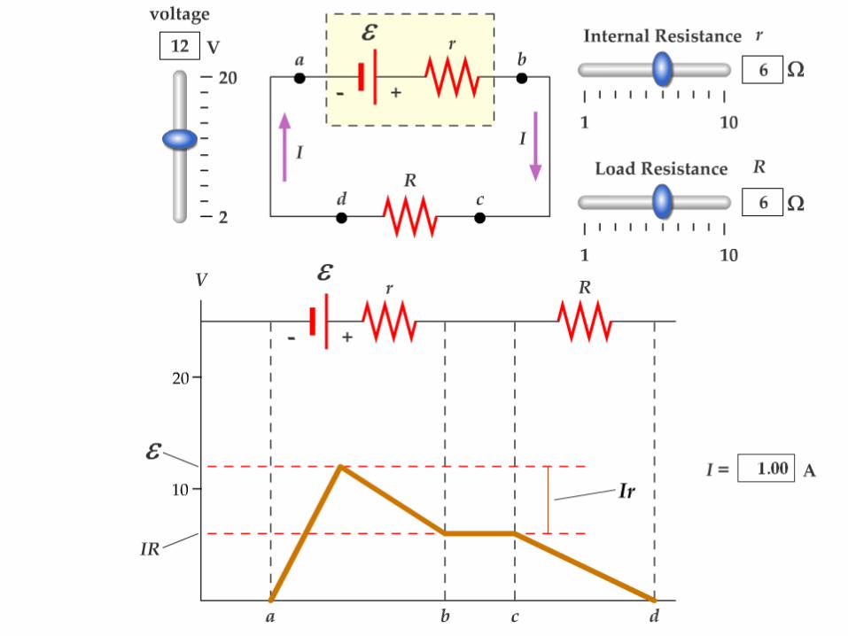
Battery ~ Internal Resistance (r)
• When a current is drawn in a circuit the actual terminal voltage delivered to the circuit is
• When a current is drawn from a battery, the terminal voltage delivered to the circuit by the battery will over time drop below its listed ε due to increasing internal resistance r.
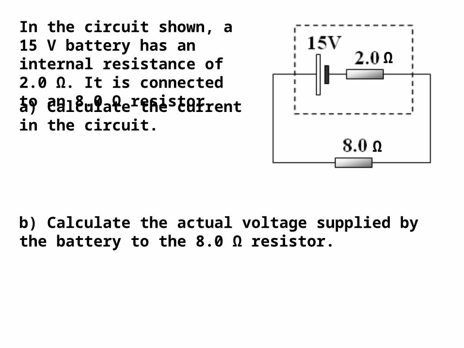
In the circuit shown, a 15 V battery has an internal resistance of 2.0 Ω. It is connected to an 8.0 Ω resistor.
a) Calculate the current in the circuit.
b) Calculate the actual voltage supplied by the battery to the 8.0 Ω resistor.
Ω
Ω
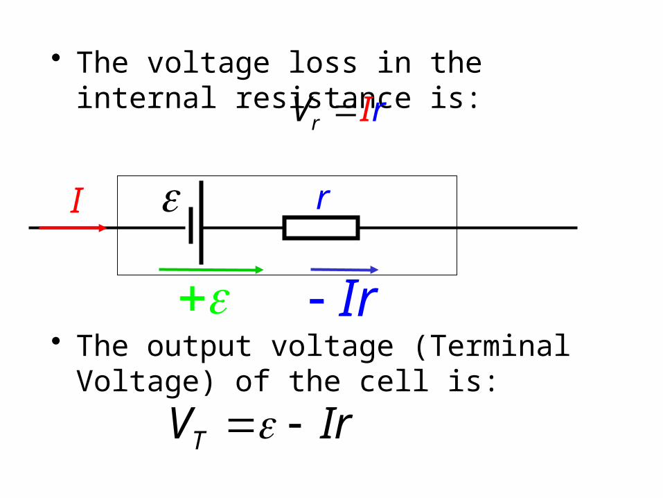
• The voltage loss in the internal resistance is:
• The output voltage (Terminal Voltage) of the cell is:
rV rI
I r
Ir
IrVT

• Notice that when the current is zero, the output voltage is the EMF.
• So the EMF can be thought of as the output voltage when the current is zero
• i.e. if an AA cell is 1.5V, this is the EMF
IrVT
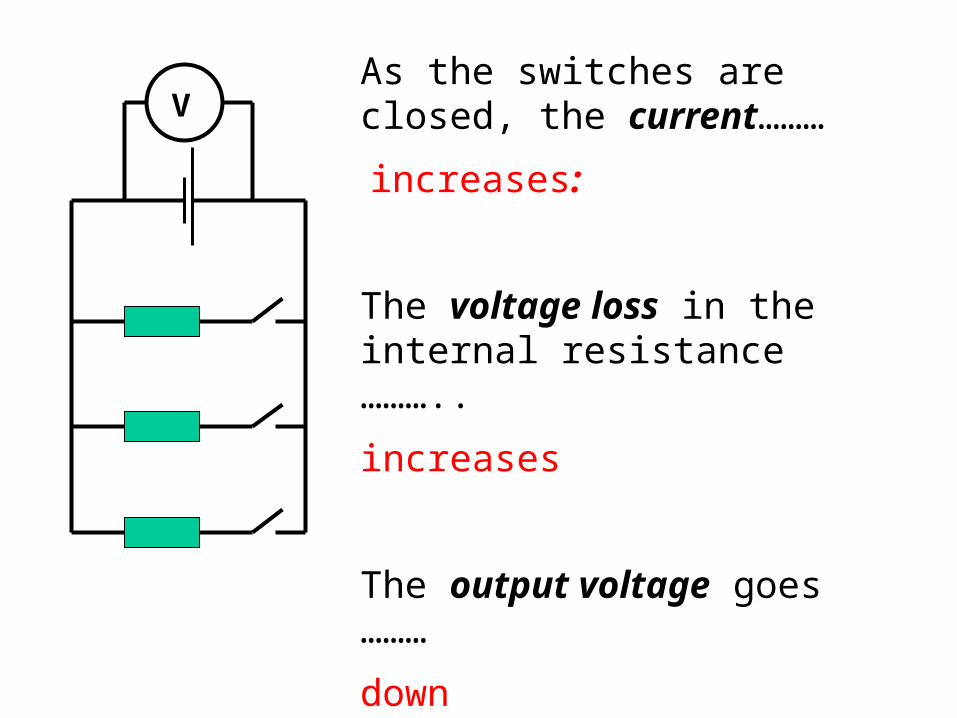
VAs the switches are closed, the current………
increases:
The voltage loss in the internal resistance ………..
increases
The output voltage goes ………
down
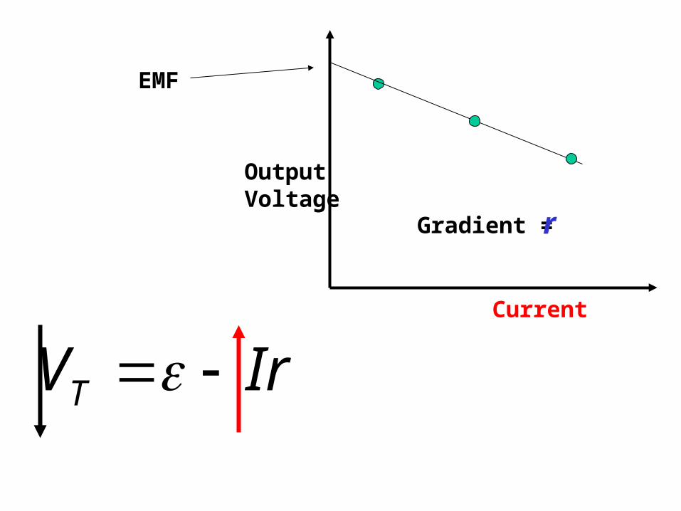
Output Voltage
Current
EMF
Gradient =r
IrVT
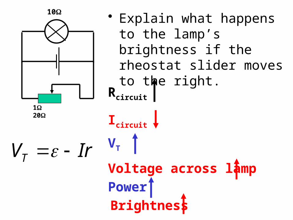
• Explain what happens to the lamp’s brightness if the rheostat slider moves to the right.
Rcircuit
Icircuit
VT
Voltage across lampPowerBrightness
1 20
10
IrVT
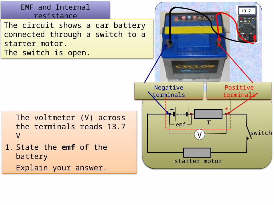
13.7EMF and Internal
resistanceThe circuit shows a car battery connected through a switch to a starter motor. The switch is open.
The voltmeter (V) across the terminals reads 13.7 V
1. State the emf of the battery
Explain your answer.
Positive terminals
Negative terminals
emf
switch
starter motor
+-r
V

13.7 EMF and Internal
resistanceThe circuit shows a car battery connected through a switch to a starter motor. The switch is open. The voltmeter (V) across the
terminals reads 13.7 V
1. State the emf of the battery
Explain your answer.• With the switch open, there is only a negligible current (mA) flowing through the voltmeter circuit.
• Negligible electrical energy is transformed into heat by the internal resistance.
• The voltmeter reads all the energy per unit of charge (V = JC-1) that is available in the battery.
• emf = Terminal voltage + Vr
• now Vr = Ir and I = 0
• emf = Terminal voltage = 13.7 V
Positive terminals
Negative terminals
emf
switch
starter motor
+
r
V
The emf = 13.7 V
-
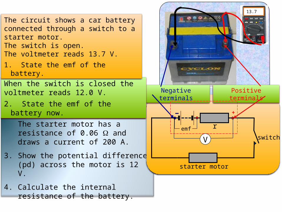
The starter motor has a resistance of 0.06 W and draws a current of 200 A.
3. Show the potential difference (pd) across the motor is 12 V.
4. Calculate the internal resistance of the battery.
13.7
Positive terminals
Negative terminals
emf
switch
starter motor
+-r
V
When the switch is closed the voltmeter reads 12.0 V.
2. State the emf of the battery now.
The circuit shows a car battery connected through a switch to a starter motor. The switch is open. The voltmeter reads 13.7 V.
1. State the emf of the battery.

When the switch is closed the voltmeter reads 12.0 V.
2. State the emf of the battery now.
emf
switch
starter motor
+-r
12
The circuit shows a car battery connected through a switch to a starter motor. The switch is open. The voltmeter reads 13.7 V.
1. State the emf of the battery.
The starter motor has a resistance of 0.06 W and draws a current of 200 A.
3. Show the potential difference (pd) across the motor is 12 V.
4. Calculate the internal resistance of the battery.
1. emf = 13.7 V
2. emf = 13.7 V
3. V = RIV = 0.06 x 200V = 12 V
4. S ΔVr = S ΔVd
ε = ΔVmotor + ΔVr
13.7 V = 12 + 1.7 V
r = V/I r = 1.7/200r = 0.009 W
CORRECT SIGNIFICANT
FIGURE
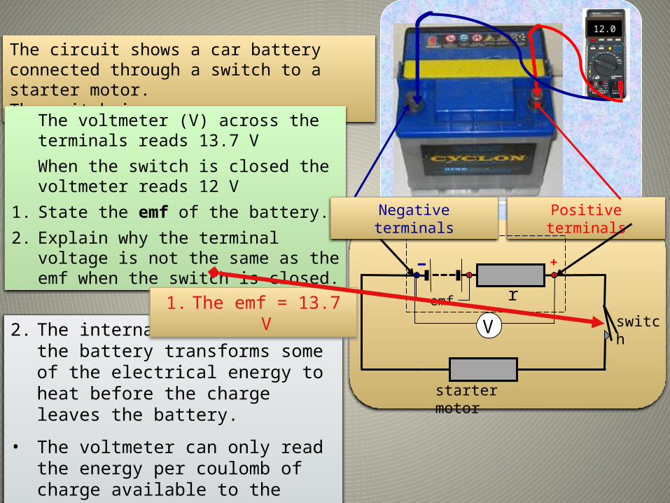
The circuit shows a car battery connected through a switch to a starter motor. The switch is open.
The voltmeter (V) across the terminals reads 13.7 V
When the switch is closed the voltmeter reads 12 V
1. State the emf of the battery.
2. Explain why the terminal voltage is not the same as the emf when the switch is closed.
2. The internal resistance of the battery transforms some of the electrical energy to heat before the charge leaves the battery.
• The voltmeter can only read the energy per coulomb of charge available to the external circuit.
Positive terminals
emf
switch
starter motor
+-r
V
Negative terminals
1. The emf = 13.7 V
13.7 12.0