ShipRight Design and construction - · PDF fileShipRight Design and construction ... D1.1 This...
16
ShipRight Design and construction Procedure for Ship Units July 2014 Appendix D Fatigue assessment of ship units adopting IMO Type B independent tanks constructed primarily of plane surfaces for the storage of liquefied gases
Transcript of ShipRight Design and construction - · PDF fileShipRight Design and construction ... D1.1 This...

ShipRight Design and construction
Procedure for Ship Units
July 2014
Appendix D Fatigue assessment of ship units adopting IMO Type B independent tanks constructed primarily of plane surfaces for the storage of liquefied gases


ShipRight Procedure for Ship Units, July 2014 - Appendix D
Lloyd’s Register
Contents
GUIDANCE ON CALCULATIONS 1
Section D1 Application 1
D2 Methodology 2
D3 Screening assessment 2
D4 Fine mesh analysis 2
D5 Fine mesh analysis 2
D6 Fatigue damage calculations for crack initiation 3
D7 Crack propagation 4
D8 Leak rates 6
D9 Weld preparation and treatment 6
D10 Construction monitoring 7
D11 Weld toe stress concentration factor for crack propagation assessment
8
D12 Stress concentration due to construction tolerances 9
D13 Newman-Raju equations 9
D14 References 11
CONTENTS


ShipRight Procedure for Ship Units, July 2014 - Appendix D
Lloyd’s Register
SECTION D1
Guidance on calculations
Section D1: ApplicationSection D2: Methodology
Section D3: Screening assessmentSection D4: Fine mesh analysis
Section D5: Construction tolerancesSection D6: Fatigue damage calculations for crack initiation
Section D7: Crack propagationSection D8: Leak rates
Section D9: Weld preparation and treatmentSection D10: Construction monitoring
Section D11: Weld toe stress concentration factor for crack propagation assessment
Section D12: Stress concentration due to construction tolerances
Section D13: Newman-Raju equationsSection D14: References
■ Section D1: Application
D1.1 This Appendix is applicable to ship units adopting IMO Type B independent tanks constructed primarily of plane surfaces for the storage of liquefied gases.
D1.2 A fatigue design assessment of the hull and the independent cargo tanks and their supporting structure is to be carried out in accordance with the ShipRight Procedure for Ship Units. This Appendix outlines additional requirements for the fatigue design
assessment of the independent cargo tanks and their supporting structure.
D1.3 Fatigue, crack propagation and leakage calculations are to be carried out for the most severely loaded tank. This may be considered representative for the remaining tanks. However, additional calculations may be required for the other tanks if they are of a different size, configuration or scantlings, or if they experience distinct loads due to their position or arrangement in the hull or loading pattern.
1

Lloyd’s Register
ShipRight Procedure for Ship Units, July 2014 - Appendix D
■ Section D2: Methodology
D2.1 A stochastic spectral fatigue approach in accordance with the ShipRight FDA Level 3 procedure [1] is required for the independent tanks. Fatigue damage from wave-induced motions (vertical, transverse and longitudinal acceleration) is to be calculated at each sea state of the long-term wave history.
D2.2 A stochastic spectral approach along the lines of the ShipRight FDA Level 3 procedure is recommended for the seats and chocks of independent tanks. In lieu of a full stochastic spectral fatigue assessment, a simplified approach based on [2] is proposed as follows:
(a) Determine the RAO’s of vertical, transverse and longitudinal accelerations at the cargo tank centroid.
(b) Determine the RAO of maximum roll angle.(c) Determine the RAO of maximum external bottom pressure
under the tank supports.(d) Select the relative wave heading and wave length giving peak
response for each of the vertical, transverse and longitudinal accelerations, maximum roll angle and external bottom pressure.
(e) Obtain design wave amplitude by scaling maximum lifetime response value with response value from unit regular wave.
(f) For each equivalent design wave condition with unique relative wave heading, wave length and wave amplitude, apply internal and external loads to full length FE model at discrete time steps over one wave cycle. At each checkpoint, determine the stress range for each design wave condition from the stress-time history. The maximum stress range from all design wave conditions is to be selected for the fatigue calculation.
D2.3 In any case, the approach for determining the long-term stress range history should be submitted to LR for approval.
D2.4 The values of principal stress in way of the weld or detail under consideration are to be amplified by concentration factors due to shape, where appropriate, and due to the maximum constructional tolerances defined by the builders.
D2.5 For initial tank scantlings estimate, the design wave approach described in D2.2 above may be employed in lieu of a full stochastic spectral approach. This approach may also be employed for selection of critical locations for subsequent verification using the full stochastic approach.
■ Section D3: Screening assessment
D3.1 Due to the numerous welded joints and hence potential crack initiation locations in a prismatic tank, a screening approach is advocated.
D3.2 In the screening analysis, the fatigue lives for the following locations: (a) Primary and secondary member face plate in way of
attachments e.g. brackets or web stiffener heel/toe boxing fillet weld connections;
(b) Tank skin fillet weld toes in way of Tee joints with primary and secondary members;
(c) Primary and secondary member face plate and tank skin butt joints
can be determined based on nominal stress and suitable design S-N curves with geometric stress concentration factor as necessary. The most critical locations identified in the screening analysis can then be chosen for further fine mesh modelling and hot spot stress assessment.
■ Section D4: Fine mesh analysis
D4.1 In way of locations identified in the screening assessment including:
(a) cruciform joints, (b) tank corner skin butts, (c) seats and chocks, (d) primary member butt joints and (e) bracket toes, hot spot stress is to be determined from fine mesh FE models.
D4.2 Four-noded shell elements of a size approximately equal to the plate thickness are acceptable.
D4.3 Surface principal stress at weld toes within +/–60 degrees of the crack plane normal should be used.
D4.4 Hot spot stress at the weld toe should be obtained by a recognised procedure commensurate with the analysis procedure and the S-N curves being used, for example, in accordance with the FDA Level 3 procedure or IIW recommendations [3].
D4.5 Edge stress may be determined using dummy rod elements.
D4.6 Stress correction due to thickness should be applied, e.g. in accordance with [1], [3] or other recognised sources, unless the S-N curves have been derived based on specific range of thickness and applied accordingly in the design. Stress correction may be omitted for moderate thicknesses up to 25 mm.
■ Section D5: Construction tolerances
D5.1 Stress concentration due to construction tolerances, (i.e. axial and angular misalignment) at butt and cruciform joints should be taken into account when determining the hot spot stress. This may be taken from [3] or other recognised sources. For the hot
SECTIONS D2, D3, D4 & D5
2

ShipRight Procedure for Ship Units, July 2014 - Appendix D
Lloyd’s Register
spot stress approach, stress concentration due to construction tolerances may be applied to the membrane component only. Additional stress concentration due to construction tolerances are generally not applicable in way of ’non-load carrying‘ joints, e.g. stiffener face crack at end connections. Lapped connections are generally to be avoided, but additional stress concentrations are to be applied where they are adopted.
D5.2 The maximum constructional tolerances for the butt and cruciform welds as proposed by the builder are to be used to determine the weld stress concentration factor caused by misalignment and angular distortion.
D5.3 Where it can be demonstrated that actual construction tolerances for panel sub-assembly welds are consistently better than those for assembly welds, for example by virtue of robotised welding assembly line, the stress concentration may be determined based on reduced misalignment and distortion at these locations.
D5.4 To obtain the total stress concentration factor, KTOTAL , for design purposes using the maximum construction tolerances the following formula is used:
KTOTAL = 1 + KM + KD
As an example, the stress concentration factors for misalignment KM, and KD for angular distortion are taken from reference [3] and reproduced in Section D12.
Alternatively, stress concentration factors due to construction tolerances may be computed using two-dimensional fine mesh finite element models. Three-dimensional models employing solid elements may be necessary in way of complex joints.
D5.5 Procedures for deriving stress concentrations due to effects of constructional tolerances should be submitted to LR for consideration at an early stage in the project and the values are to be mutually agreed before they may be applied to the design assessment of the tanks.
D5.6 The construction tolerances are required to be documented and approved by LR, preferably as part of the Construction Monitoring plan [4] or CTI plan (see D10.2).
■ Section D6: Fatigue calculations for crack initiation
D6.1 The fatigue S-N curves used for crack initiation should be derived from experimental data obtained from tests performed with parent material and configurations of welded joints with the associated consumable, welding method, welding position and post weld improvements, as applicable, for the tank material considered.
The extent of the test program and method of determining the S-N curves from the experimental data are to be agreed with LR before the start of the test programme. These results are then plotted as linear curves on logarithmic scales of stress range SR, and the number of cycles N, such that
log10 N = log10 Kd – m log10 SR or Kd = SRmN
Where, m defines the slope of the curve, and Kd is a constant appropriate to the type of detail and the survival probability, which is defined in Part 11, Chapter 4 of the Rules for Offshore Units paragraph 4.18.2.4 as 97,6 per cent. This probability level is representative of the usual assumption of the mean minus two standard deviations, signified as Kd2.
D6.2 Recognising that an extensive fatigue testing programme is costly and time consuming, for initial design purposes, reference can be made to recognised fatigue design guidelines such as [3] which contains extensive guidance on the selection of S-N curves suitable for the nominal stress and hot spot stress approach for steel and aluminium. LR will give special consideration to accepting these S-N curves for approval purposes where their application has been widely recognised.
For austenitic stainless steel and nickel steel, adjustment of these S-N curves may be made in accordance with BS 5500 [5] practice, taking into account the Young’s Modulus as given below:
whereE is the Young’s Modulus of the considered material, in N/mm2
D6.3 Cumulative fatigue damage is to be calculated in accordance with the Rules for Offshore Units, Part 11, Chapter 4, Section 4.18.2 and Section 10 of the ShipRight Procedure for Ship Units.
D6.4 Fatigue damage CW for the independent tanks and their supports should be in accordance with the Rules for Offshore Units, Part 11, Chapter 4, paragraphs 4.18.2.7 to 4.18.2.9 expanded as follows:
Primary member, CW ≤0,1, see also D6.5(a) Face butts.(b) In way of stiffener slots and other openings.(c) Face plate in way of bracket toes.(d) Cruciform joints.
Secondary members, CW ≤0,5(a) Face butts.(b) In way of end connections.(c) Bearing seats and chocks, see also D6.6 and D6.7
SECTIONS D5 & D6
3

Lloyd’s Register
ShipRight Procedure for Ship Units, July 2014 - Appendix D
Tank boundary, CW ≤0,5(a) Butt joints.(b) Tee joints.(c) In way of stud welds.(d) In way of bearing seats and chocks, see also D6.6 and D6.7
D6.5 The fatigue damage for the primary members of Type B independent cargo tanks primarily constructed of plane surfaces should not exceed 0,1. However, a larger factor up to 0,5 may be specially considered on a case-by-case basis subject to satisfactory demonstration that a crack developing on an internal primary member can be detected before it has the potential to compromise significantly the integrity of the cargo containment system.
D6.6 Fatigue design loads for individual bearing seats should be suitably increased to reflect the permissible gap size. Translational loads may be considered, assuming no sliding between the tank and its supports.
D6.7 Anti-pitch chocks may generally be omitted from fatigue assessments, assuming only collision loads will be sufficient to cause the tanks to slide. In way of anti-roll chocks, the transverse acceleration sufficient to overcome the friction between the tank and its support and cause the tank to slide is to be determined.
D6.8 The low cycle fatigue effect of differential fill on the centreline bulkhead in the independent tank (if present) and the adjacent structure is also to be assessed.
■ Section D7: Crack propagation
D7.1 Using the same stress spectra and concentration factors as for the crack iniation analysis, the propagation of an initial surface defect is computed according to the Paris law:
Where a = crack size (depth for a surface defect), and
= rate of crack growth (mm per cycle).
C and m are material constants, and ΔK is the stress intensity range which is defined as,
whereΔσ is the applied stress range and Y is a geometric factor based on the crack type and dimensions. D7.2 An initial surface weld defect, which is generally considered as the most severe defect type, is assumed for the crack propagation analysis. This is to be as specified in the yards’ QA procedures.
Typically a surface crack depth is specified based on the smallest identifiable size by the yards’ NDE capability. The design assumption is therefore that any larger defect would be found and rectified.
D7.3 The following minimum values of initial surface crack depth are proposed, based on the maximum weld toe undercut depth of 0,5 mm for primary members and 0,8 mm for secondary members permissible in JSQS [6] and defect length extracted from references [7], [8] and [9]:
• 1,0 mm deep by 5 mm length for surface crack.• 1,0 mm deep for edge crack.
Smaller values may be accepted subject to satisfactory demonstration of the yards’ quality control and NDE capability. In any case the procedure for verifying and recording the weld toe condition, as well as remedial measures in case these are exceeded, is to be agreed with LR and preferably incorporated in the Construction Monitoring plan.
D7.4 The stress intensity factor Y should be computed according to the Newman and Raju equations [10], which consider an elliptical surface defect subjected to a combination of membrane and bending stresses. These equations are included in Section D13.
D7.5 At low values of stress intensity range, propagation of a given crack does not occur. This effect can be introduced by defining a threshold value ΔKth, which depends on applied stress and crack size. All values below this level are then omitted from the integration of crack growth.
D7.6 As well as the stress concentration factors due to geometry, misalignment and angular distortion, the stress concentration Mk due to the weld toe is to be considered. This factor is a maximum on the surface at the toe, and reduces to unity at a certain distance into the thickness. A simple model is to use Mk = 3 at the surface, reducing linearly to 1,0 at 0,15t below the surface. Where it is known that the welding is to be of a high standard and is subject to 100 per cent NDE, the weld toe stress concentration factors as defined in Section D11 may be used. For example, sub-assembly panel welds should normally be of this standard.
D7.7 Where dressing of the weld toe is applied, a reduced crack depth of 40 per cent of the original is suggested and Mk may be taken as unity.
D7.8 Various values have been proposed for the material constants C and m, and for the threshold stress intensity ΔKth. The combination of these parameters may be taken from recognised standards. Lower bound values taken from [3] are given as follows for reference (in N, mm units):
SECTIONS D6 & D7
dadN
dadN
4

ShipRight Procedure for Ship Units, July 2014 - Appendix D
Lloyd’s Register
C = 5,21E-13, m = 3 and ΔKth = 63 for steel; andC = 1,41E-11, m = 3 and ΔKth = 21 for aluminium;
C and ΔKth for nickel and austenitic stainless steels may be adjusted for material elastic modulus as per BS 7910 [11] extracted below:
D7.9 Where propagation of a crack over the second half of the thickness is predicted to proceed at a much faster rate than for the first half thickness, improvement in scantlings and/or weld treatment should be considered.
D7.10 Acceptable crack depth and length should be consistent with the ‘leak before failure’ assumption behind the Type B concept. For reference only, nominal acceptance criteria for crack propagation assessment that have been accepted by LR for previous Approval in Principle of Prismatic Type B tanks for application in trading LNG ships are provided in Table D1. These criteria are largely based on references [7] and [8].
Table D1 Nominal acceptance criteria for crack propagation assessment
Primary members (girder/transverses/stringers)
Butt Up to 5 per cent of face area
Slot Up to tank plate or 25 per cent to next opening/slot
Web stiffener Full depth
Face in a way of bracket toe Up to 5 per cent of face area
Bracket toe 25 mm
Cruciform joint Penetration
Web in way of face plate termination 10 per cent of web depth
Secondary members
Stiffener 25 per cent web depth
Chock Face thickness
Seat 25 per cent web depth
Tank boundary
Plate 80 per cent plate thickness.
SECTION D7
5
Lloyd’s Register
ShipRight Procedure for Ship Units, July 2014 - Appendix D
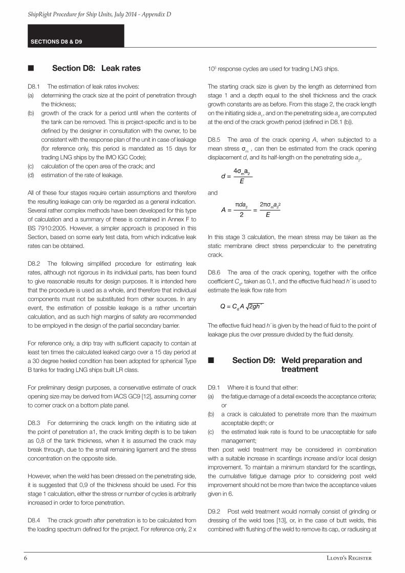
■ Section D8: Leak rates
D8.1 The estimation of leak rates involves: (a) determining the crack size at the point of penetration through
the thickness;(b) growth of the crack for a period until when the contents of
the tank can be removed. This is project-specific and is to be defined by the designer in consultation with the owner, to be consistent with the response plan of the unit in case of leakage (for reference only, this period is mandated as 15 days for trading LNG ships by the IMO IGC Code);
(c) calculation of the open area of the crack; and (d) estimation of the rate of leakage.
All of these four stages require certain assumptions and therefore the resulting leakage can only be regarded as a general indication. Several rather complex methods have been developed for this type of calculation and a summary of these is contained in Annex F to BS 7910:2005. However, a simpler approach is proposed in this Section, based on some early test data, from which indicative leak rates can be obtained.
D8.2 The following simplified procedure for estimating leak rates, although not rigorous in its individual parts, has been found to give reasonable results for design purposes. It is intended here that the procedure is used as a whole, and therefore that individual components must not be substituted from other sources. In any event, the estimation of possible leakage is a rather uncertain calculation, and as such high margins of safety are recommended to be employed in the design of the partial secondary barrier.
For reference only, a drip tray with sufficient capacity to contain at least ten times the calculated leaked cargo over a 15 day period at a 30 degree heeled condition has been adopted for spherical Type B tanks for trading LNG ships built LR class.
For preliminary design purposes, a conservative estimate of crack opening size may be derived from IACS GC9 [12], assuming corner to corner crack on a bottom plate panel.
D8.3 For determining the crack length on the initiating side at the point of penetration a1, the crack limiting depth is to be taken as 0,8 of the tank thickness, when it is assumed the crack may break through, due to the small remaining ligament and the stress concentration on the opposite side.
However, when the weld has been dressed on the penetrating side, it is suggested that 0,9 of the thickness should be used. For this stage 1 calculation, either the stress or number of cycles is arbitrarily increased in order to force penetration.
D8.4 The crack growth after penetration is to be calculated from the loading spectrum defined for the project. For reference only, 2 x
105 response cycles are used for trading LNG ships.
The starting crack size is given by the length as determined from stage 1 and a depth equal to the shell thickness and the crack growth constants are as before. From this stage 2, the crack length on the initiating side a1, and on the penetrating side a2 are computed at the end of the crack growth period (defined in D8.1 (b)).
D8.5 The area of the crack opening A, when subjected to a mean stress σm , can then be estimated from the crack opening displacement d, and its half-length on the penetrating side a2,
and
In this stage 3 calculation, the mean stress may be taken as the static membrane direct stress perpendicular to the penetrating crack.
D8.6 The area of the crack opening, together with the orifice coefficient Cd, taken as 0,1, and the effective fluid head h´ is used to estimate the leak flow rate from
The effective fluid head h´ is given by the head of fluid to the point of leakage plus the over pressure divided by the fluid density.
■ Section D9: Weld preparation and treatment
D9.1 Where it is found that either:(a) the fatigue damage of a detail exceeds the acceptance criteria;
or(b) a crack is calculated to penetrate more than the maximum
acceptable depth; or(c) the estimated leak rate is found to be unacceptable for safe
management;then post weld treatment may be considered in combination with a suitable increase in scantlings increase and/or local design improvement. To maintain a minimum standard for the scantlings, the cumulative fatigue damage prior to considering post weld improvement should not be more than twice the acceptance values given in 6.
D9.2 Post weld treatment would normally consist of grinding or dressing of the weld toes [13], or, in the case of butt welds, this combined with flushing of the weld to remove its cap, or radiusing at
SECTIONS D8 & D9
d = E
A = =
2
2
Eπda2 2πσma2
6

ShipRight Procedure for Ship Units, July 2014 - Appendix D
Lloyd’s Register
a tee junction. These methods have been determined to be effective in reducing the stress concentration caused by the weld profile, and hence increase its fatigue life.
D9.3 The first objective of the treatments discussed in 9.2 is to remove the sharp notch at the weld toe, together with all possible undercut. It would normally be recommended therefore that the toe be ground to a smooth radius extending into the parent material by a requisite depth sufficient to remove the toe flaw, but also ensuring no overgrinding. Sharp notches formed between adjacent beads of a multi-run weld should be similarly treated.
The second objective is to improve the weld surface shape, either by flushing or by radiusing. Radiusing is usually more frequently used, being normally recommended at tee junctions to avoid severe stress concentrations. Additional detailed recommendations are available from IIW recommendations [14] and Lloyd’s Register’s Fatigue Design Assessment Level 1 procedure document [15].
D9.4 Where fatigue life improvement by post weld improvement methods as described in LR’s Fatigue Design Assessment Level 1 procedure are considered, the improvement factors given therein may generally be applied. Other weld improvement methods may be specially considered. However, post weld fatigue life improvement is not accepted where root cracks may develop and generally not accepted at the design stage in way of the following locations:(a) boxing fillet welds in way of the toe and heel of web stiffener and
bracket connections between primary members and secondary stiffeners;
(b) primary member bracket toes and termination of primary member face plate.
D9.5 For reference, a builder with proven experience building prismatic Type B LNG/LPG cargo tanks has utilised weld parameter control, e.g. flank angle and toe radius, as a means to achieve acceptable notch stress concentration factors necessary to satisfy the crack initiation and propagation criteria and enhance the overall reliability of the containment system [16] and [17].
D9.6 It is considered admissible to take into consideration improved weld notch parameters in the crack initiation and growth calculations, for example by introduction of enhanced welding processes. Where weld parameter control is introduced into the design process, the consistency and repeatability of the improved weld parameters is to be adequately demonstrated to the satisfaction of LR.
D9.7 If weld grinding and/or weld profile control are specified as a fatigue design feature, the details and method of verification and recording are required to be documented and approved by LR, preferably as part of the Construction Monitoring plan or CTI plan.
■ Section D10: Construction monitoring
D10.1 The accuracy of the crack initiation and crack propagation calculations for any independent tank will depend to a large extent on the assumptions employed with respect to the construction tolerances used to determine the stress concentration factors. To ensure the integrity of the cargo tanks in service, it is important that a systematic approach be adopted during construction of the tanks to ensure that the tolerances stay within the maximum allowed for in the calculations.
D10.2 The ShipRight Construction Monitoring procedure [4] has been well established amongst Shipbuilders as a means for the enhanced monitoring in way of fatigue critical locations for the hull structure. It is considered that the CM procedure may be employed for the cargo tank structure with suitable adaptation which may form part of the tanks’ Construction, Testing and Inspection (CTI) Plan.
D10.3 The ShipRight CM (Construction Monitoring) class notation complements the strength and fatigue assessments and is mandatory. Enhanced controls in construction tolerances are to be applied and verified in accordance with the Construction Monitoring plan.
D10.4 A construction monitoring plan is required to be submitted to LR together with the supporting strength and fatigue calculations. The CM plan is required to identify the alignment method for all critical joints and the allowable construction misalignment for these joints, with remedial measures where appropriate. Where remedial measures are proposed, e.g. weld build-up and smooth dressing to compensate for larger than expected out of tolerance, its effectiveness is to be verified at the design assessment stage.
D10.5 If weld grinding and/or weld profile control are specified as a fatigue design feature, these are also to be clearly specified in the CM plan. Specification for weld grinding is to include the allowable over-grinding to remove weld toe undercuts, required weld profile shape, grinding tool burr radius, etc. If weld profile control is specified, the weld flank angle and toe radius is to be specified, and the means and extent of verification is to be suitably defined.
D10.6 Extended controls on structural alignment fit up and workmanship standards will be applied to areas of high stress concentration and fatigue criticality identified by the structural design assessment and fatigue design assessment procedures. The CM procedure is to be applied on a mandatory basis in accordance with the ShipRight Procedure for Ship Units.
SECTIONS D9 & D10
7

Lloyd’s Register
ShipRight Procedure for Ship Units, July 2014 - Appendix D
■ Section D11: Weld toe stress concentration factor for crack propagation assessment
Guidance notes for liquefied gas carriers adopting IMO TypeB independent tanks primarily constructed of plane surfaces
Guidance notes for liquefied gas carriers, Octob er 2012
Chapter 1APPENDIX 1
LLOYD’S REGISTER16
� Appendix 1: Weld toe stressconcentration factorfor crack propagationassessment
Mk = νw
, but not less than 1,0( )
whereL = width of weldt = plate thicknessa = distance from weld toe into plate
at
Loading mode
Membrane, for Mkm
Bending, for Mkb
≤2,0
>2,0
<1,0
>1,0
≤0,05 0,55( )
>0,05 0,55( )
≤0,073
≤0,073
≤0,03 0,55( )
>0,03 0,55( )
≤0,03
≤0,03
ν
0,51 0,27( )
0,83
0,615
0,83
0,45 0,21( )
0,68
0,45
0,68
w
–0,31
–0,15 0,46( )
–0,31
–0,20
–0,31
–0,19 0,21( )
–0,31
–0,19
Lt
Lt
Lt
Lt
Lt
Lt
Lt
Lt
at
Lt
a
L
t
aLt
SECTION D11
8

ShipRight Procedure for Ship Units, July 2014 - Appendix D
Lloyd’s Register
■ Section D12: Stress concentration due to construction tolerances
■ Section D13: Newman-Raju equations
Guidance notes for liquefied gas carriers adopting IMO TypeB independent tanks primarily constructed of plane surfaces
LLOYD’S REGISTER 17
Guidance notes for liquefied gas carriers, Octob er 2012
Chapter 1APPENDIX 2 & 3
� Appendix 2: Stress concentrationsdue to constructiontolerances
For misalignment between two plates of thickness t1 and t2of which t2 is the thinner, the stress concentration isobtained from:
KM = ( )where the eccentricity e is defined as
e = 0,5 (t1 – t2) + δm
It may be noted that when t1 = t1, the above reduces to
KM =
Similarly, for angular distortion
KD = + ( ) ( )where
A2 = x2 + y2
B2 = y2 – x2
x2 = 3 (1 – ν2) 2( )
y2 =
G = gauge lengthσA = mean tensile membrane stressE = modulus of elasticityν = Poisson’s ratio.
3 (1 – ν2)2G2
Dt
Gt
σA
E
6δdt
1coshA + cosB
sinBB
sinhAA
3et
t21,5
t11,5 + t21,5
6et2
� Appendix 3: Newman-Rajuequations
For an elliptical surface crack of depth a, and half length c,the following equations apply:where
∆K = ∆σ.Y.
∆σ.Y =
in which∆σm is the membrane stress range, including the
stress concentration factor due to shape∆σb is the additional bending stress range at the
surface, including stress concentration factorsdue to both shape and construction tolerances
Mkm and Mkb are the weld toe stress concentration factors for
membrane and bending stress componentsφ is the elliptic function approximated by the
expressions below, and
F = M1 + M2
2+ M3
4fφ g fw[ ( ) ( ) ]
here for 0,0 ≤ ≤0,5:
M1 = 1,13 – 0,09
M2 = –0,54 +
M3 = 0,5 – + 14,0 1,0 – 24[ ( )]
g = 1,0 + 0,1 + 0,35 2 (1,0 – sinθ)2[ ( ) ]
fθ = sin2 θ + cos2 θ0,25[ ( ) ]
ϕ = 1,0 + 1,464 1,65 0,5[ ( ) ]
and for 0,5 < ≤1,0:
M1 =0,5
1 + 0,04 ( ) [ ( )]
M2 = 0,2 4( )
π a
ca
ca
ca
a2c
ac
ac
at
ac
1,0
0,65 +a[ (c)]
0,89
0,2 +a(c)
ac
a2c
at
at
[Mkm ∆ σm + H Mkb ∆ σb] Fφ
SECTIONS D12 & D13
9

Lloyd’s Register
ShipRight Procedure for Ship Units, July 2014 - Appendix D
Guidance notes for liquefied gas carriers adopting IMO TypeB independent tanks primarily constructed of plane surfaces
Guidance notes for liquefied gas carriers, Octob er 2012
Chapter 1APPENDIX 3
LLOYD’S REGISTER18
M3 = –0,11 4( )
g = 1 + 0,1 + 0,35 2
(1,0 – sinθ)2[ ( )( ) ]
fθ = cos2 θ + 2
sin2 θ0,25[ ( ) ]
ϕ = 1 + 1,464 1,65 0,5[ ( ) ]
alsoH = H1 + (H2 – H1) sinq θ
where for 0,0 ≤ ≤0,5:
q = 0,2 + + 0,6 ( ) ( )
H1 = 1 – 0,34 – 0,11 ( ) ( )( )
H2 = 1 + G1 + G22( ) ( )
G1 = –1,22 – 0,12 ( )
G2 = 0,55 – 1,05 0,75
+ 0,47 1,5( ) ( )
and for 0,5 < ≤1,0:
q = 0,2 + + 0,6 ( ) ( )
H1 = 1,0 – 0,04 + 0,41 + 0,55 – 1,93 [ ( )]( ) [0,75
+ 1,38 1,5 2( ) ( ) ]( )
H2 = 1,0 + G1 + G22( ) ( )
G1 = 2,11 + 0,77 ( )
G2 = 0,55 – 0,72 0,75
+ 0,14 1,5( ) ( )
The plate width correction factor is defined as
fw = sec 0,5[ (( ) )]a
tπcw
ca
ca
ca
at
at
ca
ca
at
ca
at
ca
at
a2c
ac
ac
ac
at
at
at
ac
at
ac
at
a2c
ca
ca
at
ca
ca
The above expressions are normally calculated for θ = 90° atthe bottom of the elliptical crack, for propagation throughthe thickness, and at θ = 0° for lengthwise propagationalong the surface.
SECTION D13
10

ShipRight Procedure for Ship Units, July 2014 - Appendix D
Lloyd’s Register
■ Section D14: References
[1] ShipRight Fatigue – Design Assessment Level 3 Procedure, September 2009.
[2] Results of ship-motion and stress measurement on SPB LNG carrier Polar Eagle. Nakajima, Y.; Shimizu, Y.; Abe, A.; Ito, A.; Ushirokawa, O. IHI Engineering Review (Ishikawajima-Harima Heavy Industries Company); VOL. 28 ; ISSUE: 4 ; PBD: 1 Oct 1995
[3] Recommendations on fatigue design of welded joints and components, A. Hobbacher, IIW May 2009.
[4] ShipRight Construction Monitoring Procedure, May 2004.
[5] BS 5500: 1997 Specification for unfired fusion welded pressure vessels, British Standards Institute.
[6] Japanese Shipbuilding Quality Standards.
[7] The Shipbuilding Research Association of Japan; Committee RR3M, Report of studies on independent prismatic tank type B, research data no.68R, March 1978.
[8] The Shipbuilding Research Association of Japan; Committee RR3M, Report of studies on independent prismatic tank type B, research data No.78R, March 1979.
[9] Fracture mechanics analysis of independent prismatic tank of low temperature LPG carrier for verification of IMCO type B, Mitsubishi Heavy Industries Technical Journal Vo.17 No.3. 1980.
[10] Analyses of surface cracks in finite plates under tension or bending loads, J.C.Newman Jr, I.S Raju, NASA technical paper 1578, 1979.
[11] BS 7910: 2005 Guide to methods for assessing the acceptability of flaws in metallic structures, British Standards Institute.
[12] Interpretations of the IMCO code for the Construction and Equipment of Ships carrying Liquefied Gases in Bulk, International Association of Classification Societies, 2008.
[13] Improving fatigue life for aluminium cruciform joints by weld toe grinding, Naiquan Ye, Torgeir Moan,10th PRADS conference 2007 Houston USA.
[14] IIW Recommendations on post weld improvement of steel and aluminium structures, P. J. Haagensen and S. J. Maddox, XIII-2200r1-07, revised July 2008.
[15] ShipRight Fatigue – Design Assessment Level 1 Procedure – Structural Detail Design Guide, September 2009.
[16] Production process of aluminum alloy tank of SPB LNG carrier, Baba, O. Okumoto, Y. Abe, A., Journal of Light Metal Welding and Construction. 2007, VOL 45; PART 9, pages 26-35
[17] Fatigue design applied to a 5083-O/A 5183 stiffened plate structure, Japanese Society of Naval Architects spring lectures, May 1983.
SECTION D14
11

Lloyd’s Register EMEA71 Fenchurch StreetLondon EC3M 4BS, UK
T +44 (0)20 7709 9166F +44 (0)20 7488 4796E [email protected]
Lloyd’s Register ASIA22nd Floor, Dah SingFinancial Centre108 Gloucester RoadWanchai, Hong KongSAR of PR China
T +852 2287 9333F +852 2845 2616E [email protected]
www.lr.org
Lloyd’s Register Americas, Inc1330 Enclave Parkway, Suite 200HoustonTexas 77077USA
T +1 (1)281 675 3100F +1 (1)281 675 3138E [email protected]
www.lr.org
Lloyd’s Register is a trading name of Lloyd’s Register Group Limited and its subsidiaries. For further details please see http://www.lr.org/entities
Lloyd’s Register Group Limited, its affiliates and subsidiaries and their respective officers, employees or agents are, individually and collectively, referred toin this clause as ‘Lloyd’s Register’. Lloyd’s Register assumes no responsibility and shall not be liable to any person for any loss, damage or expense caused by reliance on the information or advice in this document or howsoever provided, unless that person has signed a contract with the relevant Lloyd’s Register entity for the provision of this information or advice and in that case any responsibility or liability is exclusively on the terms and conditions set out in that contract.
© Lloyd’s Register, 2014
Working togetherfor a safer world