ShipRight - Lloyd's Register · • summaries and plots of global and local ... directional and...
15
ShipRight Design and Construction Additional Design Procedures Verification of Primary Structure for Forward Holds of Container Ships September 2016 Working together for a safer world
Transcript of ShipRight - Lloyd's Register · • summaries and plots of global and local ... directional and...
ShipRight Design and Construction Additional Design Procedures Verification of Primary Structure for Forward Holds of Container Ships September 2016
Working together for a safer world

© Lloyd's Register Group Limited 2016. All rights reserved. Except as permitted under current legislation no part of this work may be photocopied, stored in a retrieval system, published, performed in public, adapted, broadcast, transmitted, recorded or reproduced in any form or by any means, without the prior permission of the copyright owner. Enquiries should be addressed to Lloyd's Register Group Limited, 71 Fenchurch Street, London, EC3M 4BS.

CONTENTS Chapter 1: .......................................................................................................................................................... 1
Introduction ........................................................................................................................................................ 1
■ Section 1: Application ........................................................................................................................................ 1
■ Section 2: Symbols ............................................................................................................................................ 1
■ Section 3: Direct calculation procedures report ................................................................................................. 2
Chapter 2: .......................................................................................................................................................... 3
Direct Calculation Procedure ............................................................................................................................. 3
■ Section 1: Objectives ......................................................................................................................................... 3
■ Section 2: Structural modelling .......................................................................................................................... 3
■ Section 3: Loading conditions ............................................................................................................................ 5
■ Section 4: Boundary conditions ......................................................................................................................... 8
■ Section 5: Acceptance criteria ......................................................................................................................... 10
Lloyd’s Register is a trading name of Lloyd’s Register Group Limited and its subsidiaries. For further details please see http://www.lr.org/entities Lloyd's Register Group Limited, its subsidiaries and affiliates and their respective officers, employees or agents are, individually and collectively, referred to in this clause as ‘Lloyd's Register’. Lloyd's Register assumes no responsibility and shall not be liable to any person for any loss, damage or expense caused by reliance on the information or advice in this document or howsoever provided, unless that person has signed a contract with the relevant Lloyd's Register entity for the provision of this information or advice and in that case any responsibility or liability is exclusively on the terms and conditions set out in that contract.

ShipRight ADP – Verification of Primary Structure for Forward Holds of Container Ships, September 2016
1
Chapter 1: Introduction
Section 1: Application Section 2: Symbols Section 3: Direct calculation procedure report
■ Section 1 Application 1.1 General 1.1.1 This ShipRight Procedure Additional Design and Construction Procedure (ADP) is optional and is
recommended to be applied to container ships with a beam greater than 32 metres and for other container ships of abnormal hull form, or of unusual structural configuration or complexity, see Pt 4, Ch 8, 1.3 of Lloyd’s Register’s Rules and Regulations for the Classification of Ships (commonly referred to as the Rules for Ships).
1.1.2 The ADP procedure requires the analysis of the primary structures of forward cargo holds under maximum bow pitching acceleration and bow immersion in a wave condition. The analysis of the ship’s structural response is to be based on a full ship three-dimensional (3-D) shell Finite Element (FE) model in accordance with the guidance given in this procedure.
1.1.3 A detailed report of the calculations is to be submitted and must include the information detailed in Section 3. The report must show compliance with the specified structural design criteria detailed in Ch 2 of this procedure.
1.1.4 If the computer programs employed are not recognised by Lloyd’s Register (LR), full particulars of the programs will also require to be submitted, see Pt 3, Ch 1, 3.1 of the Rules for Ships.
1.1.5 LR may, in certain circumstances, require the submission of computer input and output to further verify the calculations carried out.
1.1.6 Where alternative procedures are proposed, these are to be agreed with LR before commencement.
1.1.7 Container ships of unusual form or structural arrangements may need special consideration and additional calculations to those contained in this procedure may be required.
1.1.8 It is recommended that the designer discusses the analysis requirements with LR early on in the design cycle, in particular, the extent of the forward region to be analysed, see Ch 2, 1.
■ Section 2 Symbols 2.1 Symbol list 2.1.1 The symbols used in these guidance notes are defined as follows:
asurge is the longitudinal acceleration due to surge, in m/s2, given in Pt 3, Ch 14, 1.5.1 of the Rules for Ships
aheave is the vertical acceleration due to heave, in m/s2, given in Pt 3, Ch 14, 1.5.1 of the Rules for Ships
apitch is the acceleration due to pitch, in rad/s2, given in Pt 3, Ch 14, 1.5.1 of the Rules for Ships

ShipRight ADP – Verification of Primary Structure for Forward Holds of Container Ships, September 2016
2
ψ is the maximum pitch angle, in degrees, for motion case MC1 given in Pt 3, Ch 14, 1.5.1 of the Rules for Ships
φ is the maximum roll angle, in degrees, for motion case MC1 given in Pt 3, Ch 14, 1.5.1 of the Rules for Ships
xi is the longitudinal distance of the mass from the longitudinal centre of motion, as defined in Pt 3, Ch 14, 1.5.1 of the Rules for Ships
zi is the vertical distance of the mass from the vertical centre of motion, as defined in Pt 3, Ch 14, 1.5.1 of the Rules for Ships
g is the acceleration due to gravity equal to 9,81 m/s2 fap hull form coefficient given in Pt 3, Ch 14, 1.5.1 of the Rules for Ships Cp1 hull whipping factor given in Pt 3, Ch 14, 1.5.1 of the Rules for Ships
σ0 specified minimum yield stress of material
σL 235 / kL kL higher tensile steel factor given in Pt 3, Ch 2, 1.2 of the Rules for Ships
σc elastic critical buckling stress
σcr critical buckling stress corrected for plasticity effects.
2.1.2 Consistent units are to be used throughout the analysis.
2.1.3 Units used in all Rule equations are as defined in the Rules for Ships.
■ Section 3 Direct calculation procedures report 3.1 Report 3.1.1 A report is to be submitted to LR for the approval of the primary structure of the ship and is to
contain:
• list of plans used, including dates and versions;
• detailed description of structural modelling, including all modelling assumptions;
• plots to demonstrate correct structural modelling and assigned properties;
• details of material properties used;
• details of displacement boundary conditions;
• details of all still water and dynamic loading conditions reviewed with calculated shear force (SF) and bending moment (BM) distributions;
• details of the calculations for the waterlines used for the dynamic loading conditions;
• details of the acceleration factors for each loading condition;
• details of applied loadings and confirmation that individual and total applied loads are correct;
• details of boundary support forces and moments;
• plots and results that demonstrate the correct behaviour of the structural model in response to the applied loads;
• summaries and plots of global and local deflections;
• summaries and sufficient plots of von Mises, directional and shear stresses to demonstrate that the design criteria are not exceeded in any member;
• plate buckling analysis and results;
ShipRight ADP – Verification of Primary Structure for Forward Holds of Container Ships, September 2016
3
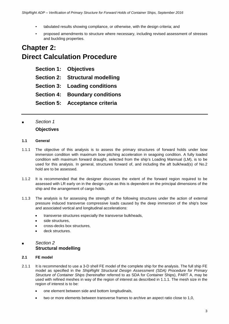
• tabulated results showing compliance, or otherwise, with the design criteria; and
• proposed amendments to structure where necessary, including revised assessment of stresses and buckling properties.
Chapter 2: Direct Calculation Procedure
Section 1: Objectives Section 2: Structural modelling Section 3: Loading conditions Section 4: Boundary conditions Section 5: Acceptance criteria
■ Section 1 Objectives 1.1 General 1.1.1 The objective of this analysis is to assess the primary structures of forward holds under bow
immersion condition with maximum bow pitching acceleration in seagoing condition. A fully loaded condition with maximum forward draught, selected from the ship’s Loading Mannual (LM), is to be used for this analysis. In general, structures forward of, and including the aft bulkhead(s) of No.2 hold are to be assessed.
1.1.2 It is recommended that the designer discusses the extent of the forward region required to be assessed with LR early on in the design cycle as this is dependent on the principal dimensions of the ship and the arrangement of cargo holds.
1.1.3 The analysis is for assessing the strength of the following structures under the action of external pressure induced transverse compressive loads caused by the deep immersion of the ship's bow and associated vertical and longitudinal accelerations:
• transverse structures especially the transverse bulkheads, • side structures, • cross-decks box structures, • deck structures.
■ Section 2 Structural modelling 2.1 FE model 2.1.1 It is recommended to use a 3-D shell FE model of the complete ship for the analysis. The full ship FE
model as specified in the ShipRight Structural Design Assessment (SDA) Procedure for Primary Structure of Container Ships (hereinafter referred to as SDA for Container Ships), PART A, may be used with refined meshes in way of the region of interest as described in 1.1.1. The mesh size in the region of interest is to be:
• one element between side and bottom longitudinals,
• two or more elements between transverse frames to archive an aspect ratio close to 1,0,

ShipRight ADP – Verification of Primary Structure for Forward Holds of Container Ships, September 2016
4
• three elements within the depth of primary stiffening.
A typical FE model with refined meshes is shown in Figure 2.2.1 A typical full ship model with finer mesh in way of the forward region.
2.1.2 Alternately, the full ship FE model specified in SDA for Container Ships, PART A, can be used with
the reduced acceptance stress criteria and increased buckling factor of safety, see Table 2.5.1 Acceptance criteria. A typical FE model is shown in Figure 2.2.2 A typical full ship model with mesh sizes specified in SDA for Container Ships.
2.1.3 A different set of stress and buckling criteria is applied to the FE model with mesh density specified
in 2.1.1 and 2.1.2. The structures is to comply with the appropriate allowable criteria given in Table 2.5.1 Acceptance criteria.
Figure 2.2.1
A typical full ship model with finer mesh in way of the forward region, see 2.1.1

ShipRight ADP – Verification of Primary Structure for Forward Holds of Container Ships, September 2016
5
Figure 2.2.2
A typical full ship model with mesh sizes specified in SDA for Container Ships, PART A, see 2.1.2 ■ Section 3 Loading conditions 3.1 Motion load case 3.1.1 A fully loaded condition with a mean draught at or equal to the scantling draught and with maximum
design container weight is to be selected from the ship’s Loading Manual for the analysis and should have the deepest forward draught. The loading condition to be considered for the analysis should be discussed and agreed with LR at the earliest opportunity.
3.1.2 The accelerations for motion case, MC3, given in Table 2.3.1 Motion load cases to be analysed are to be analysed. The stresses and buckling factors of safety are to be assessed against the criteria given in Section 5.
3.1.3 The generated loading conditions reflect the ship at:
• maximum pitch acceleration, • maximum bow pitched down associated with the deepest forward draught, • maximum upward acceleration (i.e. maximum downward inertial forces) over the ship’s forward
end.
The static and dynamic loads to be applied are summarised in Table 2.3.2 Description of load components.
Table 2.3.1 Motion load cases to be analysed
Motion load case
Longitudinal acceleration Transverse acceleration Vertical acceleration
asurge apitch g×sinψ asway aroll g×sinφ aheave aroll apitch
CxS CxP CxG CyS CyR CyG CzH CzR CzP
MC3 -0,43 1,00 -0,86 – – – -0,29 – 1,00
Note: Transverse accelerations and roll motion are omitted in this analysis.

ShipRight ADP – Verification of Primary Structure for Forward Holds of Container Ships, September 2016
6
Table 2.3.2 Description of load components
Description Remarks
Lightship • All lightweight items are to be applied with the vertical and longitudinal accelerations specified in 3.1.4.
Deadweights
• All deadweight items are to be applied with the vertical and longitudinal accelerations specified in 3.1.4.
• Pressure acting on the tank boundary of ballast and fuel oil tanks resulting from the vertical and longitudinal accelerations specified in 3.1.4. See also 3.1.8.
• Inertia forces of containers and hatch covers due to the vertical and longitudinal accelerations specified in 3.1.4. See also 3.1.6 and 3.1.7.
External pressure • External hydrostatic pressure resulting from the balanced ship on a quasi-static sinusoidal wave is to be applied, see 3.2.
Vertical hull girder bending moment • Bending moment due to the applied loads. No additional bending moment is to be applied.
3.1.4 The instantaneous accelerations, including gravitational effect, are to be obtained as follow (see Pt 3, Ch 14, 8.2.5 of the Rules for Ships):
• Longitudinal acceleration (parallel to deck, positive forward) ax = CxS asurge + CxP apitch zi - g sin(CxG ψ) m/s2
• Vertical acceleration (normal to deck, positive upwards)
az = Cp1 (CzH aheave - fap CzP apitch xi ) - g cos(CxG ψ) m/s2
where the coefficients CxS, CxP, CxG, CzH and CzP, are defined in Table 2.3.1 Motion load cases to be analysed. Other symbols in the equations are defined in Ch 1, 2.1. Note that a positive vertical acceleration generates upward inertia force and a positive longitudinal acceleration generates forward force acting on the transverse bulkhead and hatch coaming.
3.1.5 Alternatively, direct calculation procedures using an appropriate ship motion program can be used to derive the design value of the vertical and longitudinal accelerations. The applied procedure is to be agreed by LR.
3.1.6 For the containers mass above deck (on hatch covers) and the mass of the hatch covers, the inertia forces due to vertical acceleration are to be applied evenly distributed to the hatch coamings. The inertia forces due to vertical acceleration of the containers in holds (and above deck in hatchless ships) are to be applied at the stack base. To simplify the application of these loads, the containers and large equipment items should be represented by mass elements. If the FE package does not support the application of varying acceleration values, alternative methods should be discussed with LR.
3.1.7 Longitudinal inertia forces of containers, and hatch covers where fitted, are to be applied on the transverse bulkhead and cross-deck structures as described in SDA for Container Ships, PART C, Ch 2, 3.
3.1.8 For large volume tanks, the inertia loads due to the vertical and longitudinal accelerations are to be applied as pressure acting on the tank boundary, based on the accelerations calculated at the centre of gravity position of the tank. The pressure is to be calculated as follows:
P = ρc hz az + ρc lx ax where lx = is the horizontal distance from the aft end of tank to centre of the element (for a positive
longitudinal acceleration given by 3.1.4), or = is the horizontal distance from the fore end of tank to centre of the element (for a negative

ShipRight ADP – Verification of Primary Structure for Forward Holds of Container Ships, September 2016
7
longitudinal acceleration given by 3.1.4) hz = is the vertical distance from the highest point of a tank to centre of element ρc = is the density of the fluid in tank.
Other smaller tanks, such as freshwater tanks, daily-use tanks, lubricating oil tanks, the inertia loads may be represented by applying the accelerations to masses.
3.1.9 The load cases are to be evaluated using quasi-static techniques with the ship bow pitched down and balanced on a sinusoidal wave, see 3.2.
3.2 Procedure to derive external pressure
3.2.1 The longitudinal mass distribution is to be divided into convenient longitudinal sections for all lightship and deadweight items in a similar way to that required for a still water loads analysis. All components of a loading condition are to be included in the analysis. Where necessary, adjustment to the FE model is to be made to match the required lightship and Longitudinal Centre of Gravity (LCG) position of the ship.
3.2.2 The vertical acceleration at the longitudinal centre of gravity of each section is to be calculated in accordance with 3.1.4.
3.2.3 Each section of lightship and deadweight is to be multiplied by its corresponding vertical acceleration to give the combined static and dynamic load distribution.
3.2.4 The load cases are evaluated using quasi-static techniques. The ship under combined static and dynamic vertical accelerations are to be balanced, with bow pitched down, on a sinusoidal wave with a wave height of C1 (in metre), wave length of Lpp and a wave trough position at 0,65 Lpp, where C1 is defined in Pt 3, Ch 4, 5.2.1 of the Rules of Ships.
3.2.5 The effect of longitudinal acceleration may be ignored in the determination of the ship balanced position.
3.2.6 The resulting quasi-static balanced position, as illustrated in Figure 2.3.1 Quasi-static balanced position of ship on a sinusoidal wave, is to be used to apply the external hydrostatic pressures to shell plating elements. The external pressure applied to the wetted shell elements may be considered to be static and calculated as a ρwgh, where h is the vertical distance from the wave surface to the centre of the element and is ρw the density of sea-water, in tonne/m3 (specific gravity to be taken as 1,025). Figure 2.3.2 External pressure distribution resulting from balanced position shows the external pressure distribution applied.
Figure 2.3.1 Quasi-static balanced position of ship on a sinusoidal wave, see 3.2.4

ShipRight ADP – Verification of Primary Structure for Forward Holds of Container Ships, September 2016
8
Figure 2.3.2 External pressure distribution resulting from balanced position
■ Section 4 Boundary conditions 4.1 General 4.1.1 The full ship model is to be constrained at the stern in x-direction. Inertia relief is to be applied to all
other degrees of freedom. The boundary conditions are shown in Figure 2.4.1 Boundary conditions for full ship FE model.
4.1.2 Alternately, the boundary conditions specified in SDA for Container Ships, PART A, Ch 1, Sec 5, Table 1.5.1 and Figure 1.5.1, case (1) for still water load cases may be used. These boundary conditions are shown in Figure 2.4.2 Alternate boundary conditions for full ship FE model.
4.1.3 The boundary conditions described in this Section are preferred. However, other equivalent boundary conditions may be considered.
At the A.P. on the centreline: δx = 0 Inertia relief to be applied in δy, δz, θx, θy and θz
Figure 2.4.1 Boundary conditions for full ship FE model, see 4.1.1

ShipRight ADP – Verification of Primary Structure for Forward Holds of Container Ships, September 2016
9
At the F.P. on the centreline: δy = δz = 0
At the A.P. on the centreline: δx = δy = δz = 0
At the deck on the centreline at the AP: δy = 0
NOTES: (a) Care is to be taken to ensure that, within practicable limits, there is no net imbalance of load or moment in any of the six
degrees of freedom.
(b) Care is to be taken to ensure that the FE model is not over constrained.
Figure 2.4.2 Alternate boundary conditions for full ship FE model, see 4.1.2

ShipRight ADP – Verification of Primary Structure for Forward Holds of Container Ships, September 2016
10
■ Section 5 Acceptance criteria 5.1 Criteria 5.1.1 The structure is to comply with the acceptance criteria given in Table 2.5.1 Acceptance criteria.
5.1.2 The buckling capacity of plate panels is to be assessed using a plate thickness reduced by the standard thickness deduction, tc, given in Table 2.5.2 Standard thickness deductions to be used to derive critical buckling stresses.
5.1.3 The buckling factors of safety of plate panels are to be derived using the procedure that taking into account all relevant direct and shear stress components, such as Lloyd’s Register ShipRight Software’s buckling module. The average stress acting within a single plate panel may be used to assess the buckling capability.
5.1.4 The local stresses are to be increased in the ratio of of t / (t – tc), where t is the thickness used in the FE model. These local stresses may be obtained by deducting the stresses due to global bending moment generated in the FE model from the FE stresses.
5.1.5 When the calculated elastic critical buckling stress exceeds 50 per cent of the specified minimum yield stress, then the critical buckling stress is to be adjusted for the effects of plasticity using the Johnson–Ostenfeld correction formula, given below (symbols are defined in Ch 1, 2.1):
−=
ccr σ4
σ1σσ 0
0
5.1.6 In calculating the buckling factors of safety, the edge restraint factor, c, defined in Pt 3, Ch 4, 7 of the Rules for Ships, may be taken into account in calculating the critical buckling stress of wide panels subjected to compressive loading on the long edge of the panel. The edge restraint factor, c, is not to be used in the calculation of critical buckling stress for compression applied on the short edges.
5.1.7 Buckling assessment based on first principle direct calculation method may be specially considered.

ShipRight ADP – Verification of Primary Structure for Forward Holds of Container Ships, September 2016
11
Table 2.5.1 Acceptance criteria
Allowable stress (N/mm2) (see Notes 1 and 2) Buckling factor of
safety, λ Von Mises, σe
Shear stress, τ (see Note 3)
FE model with a finer mesh size as specified in 2.1.1
All members 0,75σ0 0,35σ0 1,1
FE model with a coarser mesh size as specified in SDA for Container Ships, PART A, see 2.1.2
Hatch coamings Upper decks Horizontal stringers Longitudinal bulkheads
0,63σ0 0,30σ0 1,3 (see Note 4)
Others 0,57σ0 0,30σ0 1,3 (see Note 4)
NOTES
1. For shell elements, the specified allowable stresses are to be compared with the membrane stress in the relevant structural item.
2. In areas where the openings have not been modelled, the resulting shear stress and von Mises stress are to be corrected according to the ratio of the actual to the modelled shear area. If the resulting stress level exceeds 90% of the specified allowable value, further study by means of fine mesh follow-up models may be required.
3. The specified values related to the mean shear stress over the depth of the member. The peak stress is not to exceed 1.1 × allowable value.
4. The buckling capability of the panel is to be calculated based on actual stiffening arrangement.
Table 2.5.2 Standard thickness deductions to be used to derive critical buckling stresses
Structural item Thickness deduction (mm)
Weather deck 1,0 Boundaries and internal structure of liquid tanks 1,0 Other areas 0,0

© Lloyd’s Register Group Limited 2016 Published by Lloyd’s Register Group Limited
Registered office (Reg. no. 08126909) 71 Fenchurch Street, London, EC3M 4BS
United Kingdom