
Shark-skin surfaces for fluid-drag reduction in turbulent...
33
Phil. Trans. R. Soc. A (2010) 368, 4775–4806 doi:10.1098/rsta.2010.0201 R EVIEW Shark-skin surfaces for fluid-drag reduction in turbulent flow: a review B Y B RIAN D EAN AND B HARAT B HUSHAN* Nanoprobe Laboratory for Bio- and Nanotechnology and Biomimetics (NLBB), Ohio State University, 201 West 19th Avenue, Columbus, OH 43210-1142, USA The skin of fast-swimming sharks exhibits riblet structures aligned in the direction of flow that are known to reduce skin friction drag in the turbulent-flow regime. Structures have been fabricated for study and application that replicate and improve upon the natural shape of the shark-skin riblets, providing a maximum drag reduction of nearly 10 per cent. Mechanisms of fluid drag in turbulent flow and riblet-drag reduction theories from experiment and simulation are discussed. A review of riblet-performance studies is given, and optimal riblet geometries are defined. A survey of studies experimenting with riblet- topped shark-scale replicas is also given. A method for selecting optimal riblet dimensions based on fluid-flow characteristics is detailed, and current manufacturing techniques are outlined. Due to the presence of small amounts of mucus on the skin of a shark, it is expected that the localized application of hydrophobic materials will alter the flow field around the riblets in some way beneficial to the goals of increased drag reduction. Keywords: shark skin; drag reduction; riblets; biomimetics; turbulent flow; hydrophobicity 1. Introduction Nature is full of examples of structures, materials and surfaces whose traits can be exploited for commercial application. Biomimetics, meaning to mimic biology, is the study of naturally occurring properties of plants and animals for the purpose of inspired design. By studying and understanding the mechanisms of natural phenomena, we may be able to reproduce these phenomena on demand (Bhushan 2009). Efficient design is a common trait in nature, and many structures serve multiple purposes. Lotus leaves, one example of a surface with natural traits desirable in other applications, possess a hierarchical surface structure that causes superhydrophobic behaviour (Bhushan 2008, 2010; Nosonovsky & Bhushan 2008). This allows water that comes in contact with the surface to roll off easily, picking up dirt particles and cleaning the surface along the way. Rose petals are found with superhydrophobicity and either low or high adhesion (Bhushan & Her 2010). Geckos, which can walk up walls and hang upside down, *Author for correspondence ([email protected]). One contribution of 11 to a Theme Issue ‘Green tribology’. This journal is © 2010 The Royal Society 4775 on August 30, 2018 http://rsta.royalsocietypublishing.org/ Downloaded from on August 30, 2018 http://rsta.royalsocietypublishing.org/ Downloaded from on August 30, 2018 http://rsta.royalsocietypublishing.org/ Downloaded from
Transcript of Shark-skin surfaces for fluid-drag reduction in turbulent...
Phil. Trans. R. Soc. A (2010) 368, 4775–4806doi:10.1098/rsta.2010.0201
REVIEW
Shark-skin surfaces for fluid-drag reduction inturbulent flow: a review
BY BRIAN DEAN AND BHARAT BHUSHAN*
Nanoprobe Laboratory for Bio- and Nanotechnology and Biomimetics (NLBB),Ohio State University, 201 West 19th Avenue, Columbus,
OH 43210-1142, USA
The skin of fast-swimming sharks exhibits riblet structures aligned in the direction of flowthat are known to reduce skin friction drag in the turbulent-flow regime. Structures havebeen fabricated for study and application that replicate and improve upon the naturalshape of the shark-skin riblets, providing a maximum drag reduction of nearly 10 percent. Mechanisms of fluid drag in turbulent flow and riblet-drag reduction theories fromexperiment and simulation are discussed. A review of riblet-performance studies is given,and optimal riblet geometries are defined. A survey of studies experimenting with riblet-topped shark-scale replicas is also given. A method for selecting optimal riblet dimensionsbased on fluid-flow characteristics is detailed, and current manufacturing techniques areoutlined. Due to the presence of small amounts of mucus on the skin of a shark, it isexpected that the localized application of hydrophobic materials will alter the flow fieldaround the riblets in some way beneficial to the goals of increased drag reduction.
Keywords: shark skin; drag reduction; riblets; biomimetics; turbulent flow; hydrophobicity
1. Introduction
Nature is full of examples of structures, materials and surfaces whose traits canbe exploited for commercial application. Biomimetics, meaning to mimic biology,is the study of naturally occurring properties of plants and animals for thepurpose of inspired design. By studying and understanding the mechanisms ofnatural phenomena, we may be able to reproduce these phenomena on demand(Bhushan 2009). Efficient design is a common trait in nature, and many structuresserve multiple purposes. Lotus leaves, one example of a surface with naturaltraits desirable in other applications, possess a hierarchical surface structurethat causes superhydrophobic behaviour (Bhushan 2008, 2010; Nosonovsky &Bhushan 2008). This allows water that comes in contact with the surface toroll off easily, picking up dirt particles and cleaning the surface along the way.Rose petals are found with superhydrophobicity and either low or high adhesion(Bhushan & Her 2010). Geckos, which can walk up walls and hang upside down,
*Author for correspondence ([email protected]).
One contribution of 11 to a Theme Issue ‘Green tribology’.
This journal is © 2010 The Royal Society4775
on August 30, 2018http://rsta.royalsocietypublishing.org/Downloaded from on August 30, 2018http://rsta.royalsocietypublishing.org/Downloaded from on August 30, 2018http://rsta.royalsocietypublishing.org/Downloaded from
4776 B. Dean and B. Bhushan
also possess a hierarchical structure giving them controllable super-adhesion ontheir feet (Gorb 2001; Bhushan 2007, 2010). By creating these directional super-adhesive surfaces on legs of a robot, it is possible to create a robot that can climbwalls like a gecko (Cutkosky & Kim 2009).
Nature has also created ways of reducing drag in fluid flow, evident in theefficient movement of fish, dolphins and sharks. The mucus secreted by fish causesa reduction in drag as they move through water, and also protects the fish fromabrasion, by making the fish slide across objects rather than scrape, and disease,by making the surface of the fish difficult for microscopic organisms to adhere to(Shephard 1994). It has been known for many years that by adding as little as afew hundred parts per million guar, a naturally occurring polymer, friction in pipeflow can be reduced by up to two-thirds. Other synthetic polymers provide aneven larger benefit (Hoyt 1975). The compliant skin of the dolphin has also beenstudied for drag-reducing properties. By responding to the pressure fluctuationsacross the surface, a compliant material on the surface of an object in a fluid flowhas been shown to be beneficial. Though early studies showed dramatic drag-reduction benefits, later studies have only been able to confirm 7 per cent dragreduction (Choi et al. 1997).
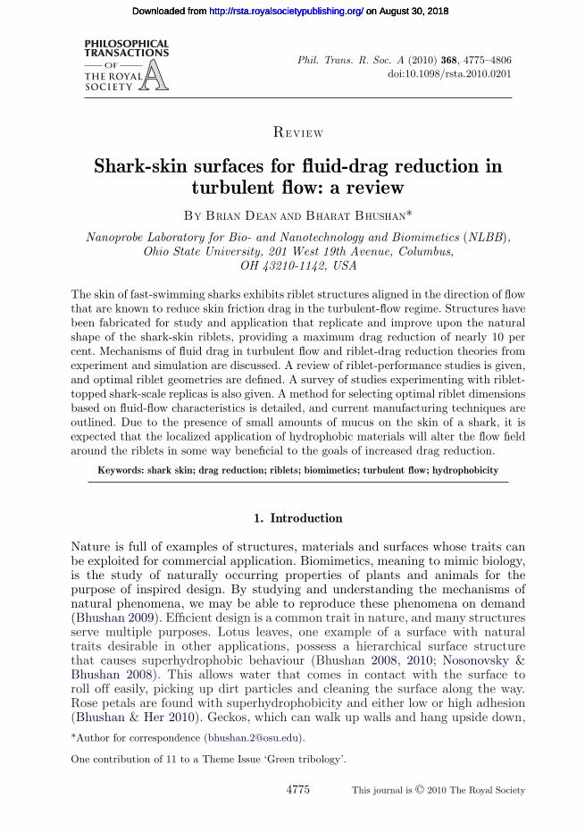
Another set of aquatic animals that possesses multi-purpose skin is fast-swimming sharks. The skin of fast-swimming sharks protects against biofoulingand reduces the drag experienced by sharks as they swim through water. Thetiny scales covering the skin of fast-swimming sharks, known as dermal denticles(skin teeth), are shaped like small riblets and aligned in the direction of fluidflow (figure 1). Shark-skin-inspired riblets have been shown to provide a drag-reduction benefit up to 9.9 per cent (Bechert et al. 1997b). The spacing betweenthese dermal denticles is such that microscopic aquatic organisms have difficultyadhering to the surface. Slower sharks are covered in dermal denticles as well, butnot those that are shaped like riblets or provide any drag-reduction benefit.
The effect of riblet structures on the behaviour of fluid flow, as well as theoptimization of their morphology, is the focus of this paper. To understandthe mechanism of shark-skin drag reduction, it is first important to understandthe nature of fluid flow over an effective shark-skin surface. Flow characteristicsand the mechanism of fluid drag will be discussed for fluid flowing over a flatplate. Mechanisms of drag reduction by riblet geometries will then be discussed,followed by a review of experimental riblet studies that have been performed, adiscussion of optimization data for common riblet geometries and other factorsin riblet selection. Large-scale and commercial applications of riblets will then beexplored, and an outlook on future research in the field will be presented.
2. Mechanisms of fluid drag
Fluid drag comes in several forms, the most basic of which are pressure dragand friction drag. Pressure or form drag is the drag associated with the energyrequired to move fluid out from in front of an object in the flow, and then backin place behind the object. Much of the drag associated with walking throughwater is pressure drag, as the water directly in front of a body must be movedout and around the body before the body can move forward. The magnitude ofpressure drag can be reduced by creating streamlined shapes. Friction or viscous
Phil. Trans. R. Soc. A (2010)
on August 30, 2018http://rsta.royalsocietypublishing.org/Downloaded from
Review. Shark-skin surfaces 4777
MakoIsurus oxyrinchus
Great hammerheadSphyrna tudes
Dusky sharkCarcharhinus obscurus
MakoIsurus oxyrinchus
Smooth hammerheadSphyrna zygena
Galapagos sharkCarcharhinus Galapagensis
Figure 1. Scale patterns on fast-swimming sharks (adapted from Reif 1985; Bechert et al. 2000a;scale bar, 0.5 mm).
drag is caused by the interactions between the fluid and a surface parallel tothe flow, as well as the attraction between molecules of the fluid. Friction dragis similar to the motion of a deck of cards sliding across a table. The frictionalinteractions between the table and the bottom card, as well as between eachsuccessive card, mimic the viscous interactions between molecules of fluid. Movingaway from the surface of an object in a fluid flow, each fluid layer has highervelocity until a layer is reached where the fluid has velocity equal to the meanflow. Fluids of higher viscosity—the attraction between molecules—have higherapparent friction between fluid layers, which increases the thickness of the fluidlayer distorted by an object in a fluid flow. For this reason, more viscous fluidshave relatively higher drag than less viscous fluids. A similar increase in dragoccurs as fluid velocity increases. The drag on an object is, in fact, a measure ofthe energy required to transfer momentum between the fluid and the object tocreate a velocity gradient in the fluid layer between the object and undisturbedfluid away from the object’s surface.
Phil. Trans. R. Soc. A (2010)
on August 30, 2018http://rsta.royalsocietypublishing.org/Downloaded from
4778 B. Dean and B. Bhushan
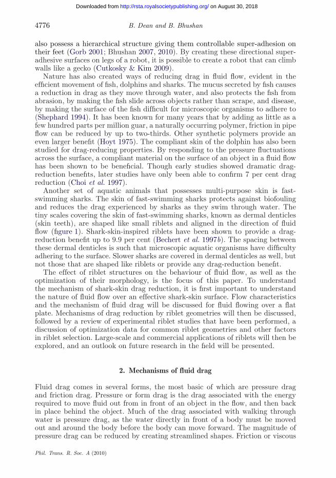
laminar turbulentflow direction
Figure 2. Transition between laminar and turbulent flow in fluid over a flat plate (adapted fromMunson et al. 2005).
The above discussion of friction drag assumes all neighbouring fluid moleculesmove in the same relative direction and momentum transfer occurs between layersof fluid flowing at different velocities. Figure 2 shows an image of the transitionbetween laminar flow and turbulent flow, in which molecules move in swirling andcross-stream motions such that an average velocity is maintained in the directionof flow. The inclusion of cross-flow and non-parallel relative velocities betweenmolecules in turbulent flow causes a dramatic increase in momentum transfer.The cross-flow momentum transfer is of particular interest, as all momentumtransferred parallel to the surface of an object results in a corresponding increasein drag. Natural transition occurs from laminar- to turbulent-flow regimes neara Reynolds number around 4000 for pipe flow and 500 000 for flow over a flatplate. The Reynolds number, Re, is a ratio of the inertial forces to viscous forcesin a given flow. For pipe flow, Re = rVD/m, where r is the fluid density, V is thevelocity, D is the pipe diameter and m is the dynamic viscosity. For flow over aflat plate, Re = rVL/m, where L is the length. For values of Re much less than thetransition values above, flow is laminar—dominated by viscous forces between themolecules. For larger values of Re, the flow is turbulent—dominated by inertialforces of the system (Munson et al. 2005).
Fully developed turbulent flow is commonly said to exhibit completerandomness in its velocity distribution, but there exist distinct regions within fullydeveloped turbulent flow that exhibit different patterns and flow characteristics(Kline et al. 1967). While organization is evident in the viscous sublayer, thelayer closest to the surface, the outer layers of the turbulent boundary layer arechaotic and disorganized. Much of this chaotic motion above the viscous sublayeris caused by the outward bursting of the streamwise vortices that form at thesurface in the viscous sublayer. Streamwise vortices (vortices that rotate aboutaxes in the direction of mean velocity) dominate the viscous sublayer. As thesevortices rotate and flow along the surface, they naturally translate across thesurface in the cross-flow direction. The interaction between the vortices and thesurface, as well as between neighbouring vortices that collide during translation
Phil. Trans. R. Soc. A (2010)
on August 30, 2018http://rsta.royalsocietypublishing.org/Downloaded from

Review. Shark-skin surfaces 4779
flat plate
riblet
h+ = 12.6
s+ = 25.2
h+ = 20.3
s+ = 40.6
(a) (b)
(c) (d)
Figure 3. Turbulent-flow visualization of streamwise vortices in a vertical cross section over aflat plate: (a) drag decreasing case (V = 3 m s−1) and (b) drag increasing case (V = 5 m s−1).Riblet surfaces: (c) drag decreasing case (V = 3 m s−1) and (d) drag increasing case (V = 5 m s−1).Adapted from Lee & Lee (2001).
initiate bursting motions where vortices are rapidly ejected from the surface andinto the outer boundary layers. As vortices are ejected, they tangle with othervortices and twist such that transient velocity vectors in the cross-stream directioncan become as large as those in the average flow direction (Kline et al. 1967). Thetranslation, bursting of vortices out of the viscous sublayer and chaotic flow inthe outer layers of the turbulent boundary-layer flow are all forms of momentumtransfer and are large factors in fluid drag. Reducing the bursting behaviour ofthe streamwise vortices is a critical goal of drag-reduction, as the drag-reductionpossibilities presented by this are sizable.
The vortices were first visualized from a horizontal cross section and wereseen as high- and low-speed streaks aligned in the mean-flow direction (Coles1978). Later, a full Navier–Stokes simulation was used to replicate the high-and low-speed streaks (Robinson 1991), and more recently flow-visualizationtechniques were used to capture cross-sectional images, shown in figure 3, of the
Phil. Trans. R. Soc. A (2010)
on August 30, 2018http://rsta.royalsocietypublishing.org/Downloaded from
4780 B. Dean and B. Bhushan
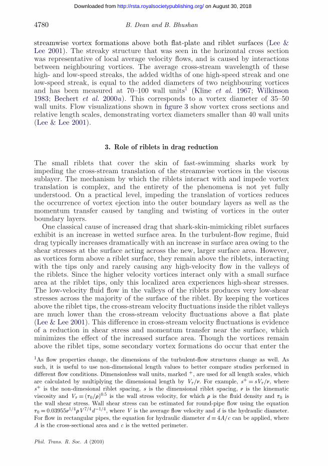
streamwise vortex formations above both flat-plate and riblet surfaces (Lee &Lee 2001). The streaky structure that was seen in the horizontal cross sectionwas representative of local average velocity flows, and is caused by interactionsbetween neighbouring vortices. The average cross-stream wavelength of thesehigh- and low-speed streaks, the added widths of one high-speed streak and onelow-speed streak, is equal to the added diameters of two neighbouring vorticesand has been measured at 70–100 wall units1 (Kline et al. 1967; Wilkinson1983; Bechert et al. 2000a). This corresponds to a vortex diameter of 35–50wall units. Flow visualizations shown in figure 3 show vortex cross sections andrelative length scales, demonstrating vortex diameters smaller than 40 wall units(Lee & Lee 2001).
3. Role of riblets in drag reduction
The small riblets that cover the skin of fast-swimming sharks work byimpeding the cross-stream translation of the streamwise vortices in the viscoussublayer. The mechanism by which the riblets interact with and impede vortextranslation is complex, and the entirety of the phenomena is not yet fullyunderstood. On a practical level, impeding the translation of vortices reducesthe occurrence of vortex ejection into the outer boundary layers as well as themomentum transfer caused by tangling and twisting of vortices in the outerboundary layers.
One classical cause of increased drag that shark-skin-mimicking riblet surfacesexhibit is an increase in wetted surface area. In the turbulent-flow regime, fluiddrag typically increases dramatically with an increase in surface area owing to theshear stresses at the surface acting across the new, larger surface area. However,as vortices form above a riblet surface, they remain above the riblets, interactingwith the tips only and rarely causing any high-velocity flow in the valleys ofthe riblets. Since the higher velocity vortices interact only with a small surfacearea at the riblet tips, only this localized area experiences high-shear stresses.The low-velocity fluid flow in the valleys of the riblets produces very low-shearstresses across the majority of the surface of the riblet. By keeping the vorticesabove the riblet tips, the cross-stream velocity fluctuations inside the riblet valleysare much lower than the cross-stream velocity fluctuations above a flat plate(Lee & Lee 2001). This difference in cross-stream velocity fluctuations is evidenceof a reduction in shear stress and momentum transfer near the surface, whichminimizes the effect of the increased surface area. Though the vortices remainabove the riblet tips, some secondary vortex formations do occur that enter the
1As flow properties change, the dimensions of the turbulent-flow structures change as well. Assuch, it is useful to use non-dimensional length values to better compare studies performed indifferent flow conditions. Dimensionless wall units, marked +, are used for all length scales, whichare calculated by multiplying the dimensional length by Vt/n. For example, s+ = sVt/n, wheres+ is the non-dimesional riblet spacing, s is the dimensional riblet spacing, n is the kinematicviscosity and Vt = (t0/r)0.5 is the wall stress velocity, for which r is the fluid density and t0 isthe wall shear stress. Wall shear stress can be estimated for round-pipe flow using the equationt0 = 0.03955n1/4rV 7/4d−1/4, where V is the average flow velocity and d is the hydraulic diameter.For flow in rectangular pipes, the equation for hydraulic diameter d = 4A/c can be applied, whereA is the cross-sectional area and c is the wetted perimeter.
Phil. Trans. R. Soc. A (2010)
on August 30, 2018http://rsta.royalsocietypublishing.org/Downloaded from
Review. Shark-skin surfaces 4781
apparent flow origins
mean velocity profiles
hps
hpc
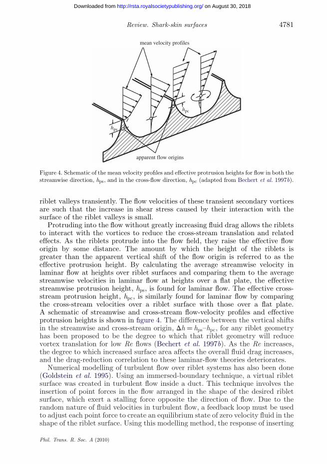
Figure 4. Schematic of the mean velocity profiles and effective protrusion heights for flow in both thestreamwise direction, hps, and in the cross-flow direction, hpc (adapted from Bechert et al. 1997b).
riblet valleys transiently. The flow velocities of these transient secondary vorticesare such that the increase in shear stress caused by their interaction with thesurface of the riblet valleys is small.
Protruding into the flow without greatly increasing fluid drag allows the ribletsto interact with the vortices to reduce the cross-stream translation and relatedeffects. As the riblets protrude into the flow field, they raise the effective floworigin by some distance. The amount by which the height of the riblets isgreater than the apparent vertical shift of the flow origin is referred to as theeffective protrusion height. By calculating the average streamwise velocity inlaminar flow at heights over riblet surfaces and comparing them to the averagestreamwise velocities in laminar flow at heights over a flat plate, the effectivestreamwise protrusion height, hps, is found for laminar flow. The effective cross-stream protrusion height, hpc, is similarly found for laminar flow by comparingthe cross-stream velocities over a riblet surface with those over a flat plate.A schematic of streamwise and cross-stream flow-velocity profiles and effectiveprotrusion heights is shown in figure 4. The difference between the vertical shiftsin the streamwise and cross-stream origin, Dh = hps–hpc, for any riblet geometryhas been proposed to be the degree to which that riblet geometry will reducevortex translation for low Re flows (Bechert et al. 1997b). As the Re increases,the degree to which increased surface area affects the overall fluid drag increases,and the drag-reduction correlation to these laminar-flow theories deteriorates.
Numerical modelling of turbulent flow over riblet systems has also been done(Goldstein et al. 1995). Using an immersed-boundary technique, a virtual ribletsurface was created in turbulent flow inside a duct. This technique involves theinsertion of point forces in the flow arranged in the shape of the desired ribletsurface, which exert a stalling force opposite the direction of flow. Due to therandom nature of fluid velocities in turbulent flow, a feedback loop must be usedto adjust each point force to create an equilibrium state of zero velocity fluid in theshape of the riblet surface. Using this modelling method, the response of inserting
Phil. Trans. R. Soc. A (2010)
on August 30, 2018http://rsta.royalsocietypublishing.org/Downloaded from

4782 B. Dean and B. Bhushan
100(a)
(b)
50
0y+
y+
–50
–60
–80
–100
–120
240 260 280 300 320 340
–100
0 100 200 300
1.8583.7165.5747.4329.29011.14913.00714.86516.723
VVτ
1.8583.7165.5747.4329.29011.14913.00714.86516.723
z+
z+
VVτ
Figure 5. Plots showing numerically simulated flow through a duct with a virtual riblet surfaceon the bottom and a flat surface on the top. A magnified view of a region of interest from theduct in (a) is shown in (b). Virtual riblets have a sawtooth cross section with h/s ∼ 0.29. Non-dimensionalized length scales used for dimensions parallel and normal to the surfaces are z+ andy+, respectively. Lines of constant velocity are shown, as well as velocity vectors. Regions of similarflow velocity are plotted using a ratio of velocity, V , to wall stress velocity Vt = (t0/r)0.5 (adaptedfrom Goldstein et al. 1995).
a riblet surface into a turbulent flow can be monitored to better understandthe mechanisms of drag reduction. In their study, Goldstein et al. (1995) firstinserted virtual flat-plate boundaries in laminar and turbulent flow over a flatplate. These tests benchmarked the capability of the point forces to accuratelyrepresent a stagnant boundary in steady flow and the capability of the feedbackloop to accurately model a boundary in unsteady flow, respectively. Building fromthese platforms, two virtual riblet surfaces were tested in turbulent flow. Velocitycontours from one of these virtual riblet surfaces can be seen in figure 5. Thesesurfaces performed similarly to similar physical riblet surfaces, and showed up to
Phil. Trans. R. Soc. A (2010)
on August 30, 2018http://rsta.royalsocietypublishing.org/Downloaded from
Review. Shark-skin surfaces 4783
3.3 per cent drag reduction when compared with a flat surface. Analysis of themodelled flow fields over the riblet surfaces is in consensus with existing theoriesof drag-reduction mechanisms. As vortices form on the surface, they remain abovethe riblet tips, which creates a low-velocity channel in the riblet valleys. The low-velocity channel between riblet tips has a lower velocity gradient than flow overa flat plate, which reduces shear stresses over most of the riblet surface. Velocitygradients are higher at the riblet tips, and shear stresses are correspondinglyhigher. The net result of this shear-stress distribution is a favourable decrease inoverall drag. Also, vortex translation across the riblet surface during animationswas noticeably damped in comparison to flow over a flat plate. Damped vortextranslation serves to reduce the occurrence of vortex bursting, tangling and outer-layer turbulence.
4. Optimization of riblet geometry
The cross-sectional shape of riblets on fast-swimming sharks varies greatly,even at different locations on the same shark. Figure 1 shows the differencebetween the separated blade riblets on the tail of a Shortfin Mako shark, Isurusoxyrinchus, with the scale-grouped riblets on its front section, as well as themorphology that exists on various other fast-swimming sharks. Many types ofriblets have been studied, the shapes of which have been chosen for severalreasons. Riblet shapes have been chosen for their similarity to natural riblets,for their ease of fabrication and for purposes of drag-reduction optimization.Two-dimensional riblets, which have a continuous extrusion of a simple crosssection in the streamwise direction, have been most extensively characterized.The most thorough characterization has been completed for symmetrical two-dimensional riblets with sawtooth, scalloped and blade cross sections, as shownin figure 6 (Walsh 1980, 1982; Walsh & Lindemann 1984; Bechert & Hoppe 1985;Bechert et al. 1986, 1997a, 2000a,b; Wilkinson & Lazos 1987; Wilkinson et al.1988; Walsh & Anders 1989). Alternative riblet geometries have, in general, shownno increased benefit. These riblets, including asymmetrical riblets, hierarchicalriblets and riblets with rounded or notched peaks have been studied in detailand do not improve upon the benefit of standard driblet geometries (Walsh 1980,1982; Walsh & Lindemann 1984). Other two-dimensional riblet shapes that havebeen studied include alternating brother–sister type riblets (Bechert et al. 1997a)and hierarchical riblets with small riblets on top of larger riblets (Wilkinson &Lazos 1987). Three-dimensional riblets, which include segmented two-dimensionalriblets as well as shark-skin mouldings and replicas have also been studied.Riblet types characterized include aligned segmented-blade riblets (Wilkinson &Lazos 1987), offset segmented-blade riblets (Bechert et al. 2000a), offset-three-dimensional blade riblets (Bechert et al. 2000a) and three-dimensional shark-skinreplicas (Bechert et al. 2000b; Lang et al. 2008; Jung & Bhushan 2010).
Most studies are done by changing the non-dimensionalized spacing, s+,by varying only fluid velocity and collecting shear-stress data from a shear-stress balance in a wind tunnel or fluid-flow channel. Pipe-flow tests will bediscussed as well. Measured shear stress is compared with shear stress over aflat plate and plotted against the calculated s+ value for the flow conditions.In this manner, a performance curve is created for a riblet array with a
Phil. Trans. R. Soc. A (2010)
on August 30, 2018http://rsta.royalsocietypublishing.org/Downloaded from
4784 B. Dean and B. Bhushan
a
s
h
4(a)
(b)
2
0
–2
Dt/t
o (%
)
–4
–6
–8
–105 10 15 20 25 30 35
s+
5 10 15 20 25 30 35s+
t
h
s
4
2
0
–2
Dt/t
o (%
)
–4
–6
–8
–10
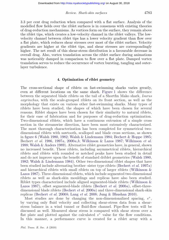
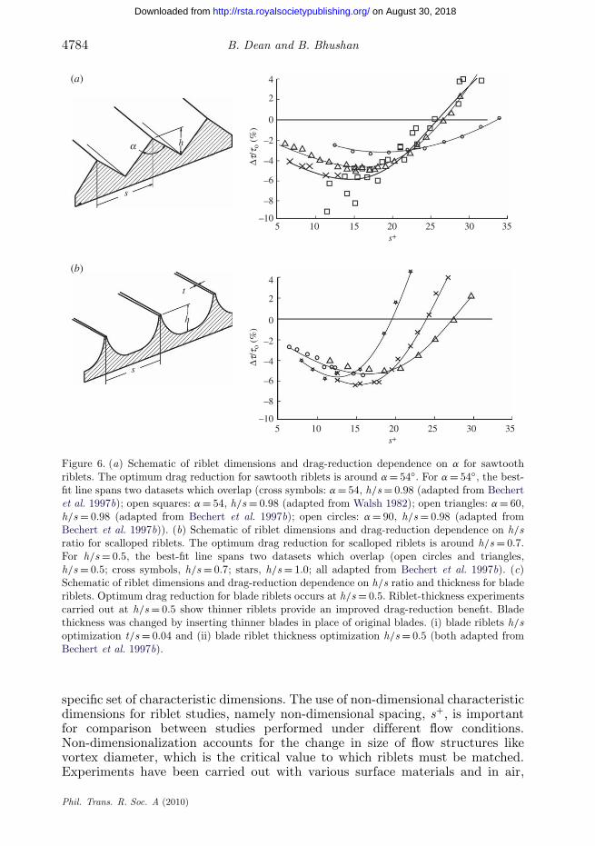
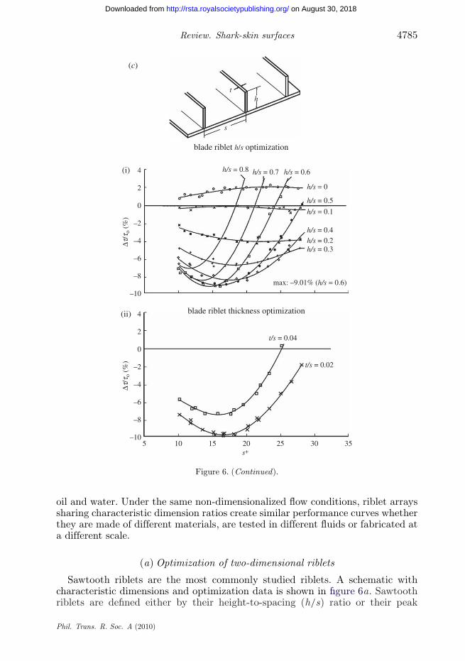
Figure 6. (a) Schematic of riblet dimensions and drag-reduction dependence on a for sawtoothriblets. The optimum drag reduction for sawtooth riblets is around a = 54◦. For a = 54◦, the best-fit line spans two datasets which overlap (cross symbols: a = 54, h/s = 0.98 (adapted from Bechertet al. 1997b); open squares: a = 54, h/s = 0.98 (adapted from Walsh 1982); open triangles: a = 60,h/s = 0.98 (adapted from Bechert et al. 1997b); open circles: a = 90, h/s = 0.98 (adapted fromBechert et al. 1997b)). (b) Schematic of riblet dimensions and drag-reduction dependence on h/sratio for scalloped riblets. The optimum drag reduction for scalloped riblets is around h/s = 0.7.For h/s = 0.5, the best-fit line spans two datasets which overlap (open circles and triangles,h/s = 0.5; cross symbols, h/s = 0.7; stars, h/s = 1.0; all adapted from Bechert et al. 1997b). (c)Schematic of riblet dimensions and drag-reduction dependence on h/s ratio and thickness for bladeriblets. Optimum drag reduction for blade riblets occurs at h/s = 0.5. Riblet-thickness experimentscarried out at h/s = 0.5 show thinner riblets provide an improved drag-reduction benefit. Bladethickness was changed by inserting thinner blades in place of original blades. (i) blade riblets h/soptimization t/s = 0.04 and (ii) blade riblet thickness optimization h/s = 0.5 (both adapted fromBechert et al. 1997b).
specific set of characteristic dimensions. The use of non-dimensional characteristicdimensions for riblet studies, namely non-dimensional spacing, s+, is importantfor comparison between studies performed under different flow conditions.Non-dimensionalization accounts for the change in size of flow structures likevortex diameter, which is the critical value to which riblets must be matched.Experiments have been carried out with various surface materials and in air,
Phil. Trans. R. Soc. A (2010)
on August 30, 2018http://rsta.royalsocietypublishing.org/Downloaded from
Review. Shark-skin surfaces 4785
(c)
blade riblet h/s optimization
blade riblet thickness optimization
th
s
4(i)
(ii)
2
0
–2
Dt/t
o (%
)
–4
–6
–8
–10
4
2
0
–2
Dt/t
o (%
)
–4
–6
–8
–10
max: –9.01% (h/s = 0.6)
5 10 15 20 25 30 35s+
h/s = 0.8
t/s = 0.04
t/s = 0.02
h/s = 0.7 h/s = 0.6
h/s = 0
h/s = 0.5
h/s = 0.1
h/s = 0.4h/s = 0.2h/s = 0.3
Figure 6. (Continued).
oil and water. Under the same non-dimensionalized flow conditions, riblet arrayssharing characteristic dimension ratios create similar performance curves whetherthey are made of different materials, are tested in different fluids or fabricated ata different scale.
(a) Optimization of two-dimensional riblets
Sawtooth riblets are the most commonly studied riblets. A schematic withcharacteristic dimensions and optimization data is shown in figure 6a. Sawtoothriblets are defined either by their height-to-spacing (h/s) ratio or their peak
Phil. Trans. R. Soc. A (2010)
on August 30, 2018http://rsta.royalsocietypublishing.org/Downloaded from
4786 B. Dean and B. Bhushan
4
2
0
–2
Dt/t
o (%
)–4
–6
–8
–105 10 15 20 25 30 35
s+
(a)
sawtooth riblets with h/s = 0.5
scalloped riblets with h/s = 0.5
blade riblets with h/s = 0.5
s
h
hps ≈ 0.14 s
hps ≈ 0.19 s
DO
hDO
hps ≈ 0.21 s
hDO
s
s
lines of constant velocityflat-plate flowforce lines
(b)
Figure 7. (Caption opposite.)
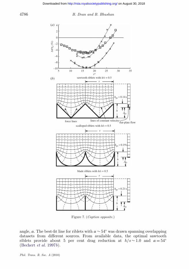
angle, a. The best-fit line for riblets with a ∼ 54◦ was drawn spanning overlappingdatasets from different sources. From available data, the optimal sawtoothriblets provide about 5 per cent drag reduction at h/s ∼ 1.0 and a = 54◦(Bechert et al. 1997b).
Phil. Trans. R. Soc. A (2010)
on August 30, 2018http://rsta.royalsocietypublishing.org/Downloaded from
Review. Shark-skin surfaces 4787
Figure 7. (Opposite.) (a) Drag-reduction comparison for sawtooth, scalloped and blade riblets withh/s = 0.5 (open square: sawtooth, h/s = 0.86, a = 60; cross symbols: scalloped, h/s = 0.7; filledcircle: blade, h/s = 0.5, t/s = 0.02; data from Bechert et al. (1997b)). (b) Schematic of lines ofconstant velocity above riblet and flat-plate surfaces in laminar flow allow for a comparison ofeffective protrusion height, hp, of sawtooth, scalloped and blade riblets. The effective protrusionheight, which is favourable for the reduction of vortex-translation reduction, is the differencebetween the riblet height, h, and the upward shift in the effective flow origin, DO; hp = DO– h. Tofind the upward shift in the effective flow origin, the height and velocity of the lowest undisturbedline of constant velocity above a riblet surface are determined. Next, the height at which flow overa flat plate reaches the same velocity is determined. The difference between these two heights isthe upward shift in the effective flow origin. Blade riblets have the largest effective protrusionheight. Scalloped riblets have the second largest, and sawtooth riblets have the lowest of the three(adapted from Bechert et al. 1986, 1997b).
Scalloped riblets are most commonly defined by their h/s ratio, but test shapeshave varied between research groups. While the basic shapes are similar, noconsensus has been formed about a standard scalloped profile. Generally, anyconcave shape may be referred to as scalloped and comparing data betweensawtooth-, scalloped- and blade-riblet optimizations will support a generalizationof comparable shapes. Ideally, the tip of the riblet is thin and sharp, butscalloped riblets with measurable tip thicknesses have also produced favourableresults. Figure 6b shows optimization data for scalloped riblets. A maximum dragreduction of 6.5 per cent has been achieved for scalloped riblets with h/s ∼ 0.7(Bechert et al. 1997b).
Blade riblets have been rigorously studied in their characteristic dimensionratios. A schematic with characteristic dimensions and optimization data forblade riblets is in figure 6c. By fabricating an adjustable blade-riblet test stand,a 9.9 per cent drag reduction was achieved with optimized dimensions of h/s ∼0.5 and t/s = 0.02 was found (Bechert et al. 1997b). Due to their inherentweak structure, optimal blade riblet thickness is limited by strength, not fluiddynamics. Blades that are too thin will warp in fluid flow and allow vortices totranslate as a result.
When comparing the optimal drag-reduction geometries for sawtooth,scalloped and blade riblets shown in figure 7a, it is clear that blade riblets providethe highest level of drag reduction, scalloped riblets provide the second most, andsawtooth riblets provide the least benefit. A summary of comparison features forsawtooth, scalloped and blade riblets is given in table 1. In general, it can beseen in figure 6 that each type of riblet is most beneficial near s+ ∼ 15, which isbetween one-third and one-half of the width of the streamwise vortices. Largers+ will cause vortices to begin falling into the gap between the riblets, whichincreases the shear stress at the surface between riblets. As s+ decreases belowoptimum, the overall size of the riblets decreases to a point below which theycannot adequately impede vortex translation.
Comparing drag-reduction benefit potential to effective protrusion height inthe streamwise direction, it is apparent that increased protrusion height iscorrelated to drag-reduction potential. Figure 7b shows the effective streamwiseprotrusion height for sawtooth, scalloped and blade riblets. For the same h/s,blade riblets have the smallest shift in the effective flow origin owing to their smallcross-sectional area, and sawtooth riblets have the largest shift in the effective
Phil. Trans. R. Soc. A (2010)
on August 30, 2018http://rsta.royalsocietypublishing.org/Downloaded from
4788 B. Dean and B. Bhushan
30 flow direction riblets
b25
20
15
10
Dt/t
o (%
)
5
0
–5
–105 10 15 20 25 30 35
s+
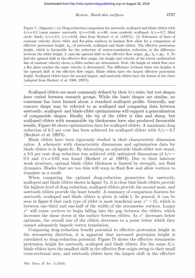
Figure 8. Drag-reduction dependence on yaw angle, b, of sawtooth riblets in free stream forh/s ≈ 0.62 (adapted from Walsh & Lindemann 1984). Open circles, b = 0; open squares; b = 15,open triangles, b = 30.
Table 1. Summary and comparison of optimum riblet geometry for various riblet shapes.
relative maximum drag optimumriblet shape ranka reduction (%)b geometryb comments
sawtooth 3 5 h/s ∼ 1, a ∼ 60◦ most durablescalloped 2 6.5 h/s ∼ 0.7blade 1 9.9 h/s ∼ 0.5 drag reduction increases as riblet
thickness decreases; durability isan issue
a1 corresponds to greatest drag reduction.bBased on the published data in Bechert et al. (1997b).
flow origin. Though all three profiles share a calculated maximum streamwiseprotrusion height of 0.2206 s at separate values of h/s, an increase in overall dragis experienced at these values owing to the increased drag contributions of surfaceshear-stress effects on the increased surface area in the turbulent regime (Bechertet al. 1986). The height at which hp is maximized causes such an increase ineffective flow origin shift that the drag-reduction benefits are outweighed.
An additional concern to the application of riblets is the sensitivity of dragreduction to yaw angle. Yaw angle, the angle between the average flow directionand the riblet orientation, has a deleterious effect on the drag-reduction benefitsof riblet surfaces. Riblet surfaces become drag inducing above b = 30◦, but smalldrag reductions can still be seen up to b = 15◦ (Walsh & Lindemann 1984).Figure 8 shows the effects of yaw angle on riblet performance for flow oversawtooth riblets.
(b) Studies with three-dimensional riblets
Riblets on shark skin exist in short segments and groups, not as continuousstructures. Riblets with three-dimensional features have been created to betterapproximate the performance of actual shark skin and to determine whether
Phil. Trans. R. Soc. A (2010)
on August 30, 2018http://rsta.royalsocietypublishing.org/Downloaded from
Review. Shark-skin surfaces 4789
8.3 4.6
2.7545°45°1.6 r 1.6 r
4
(a)
(b)
continuous blade
t/s ~ 0.02
staggered
2
0
–2
Dt/t
o (%
)
–4
–6
–8
–105 10 15 20 25 30 35
s+
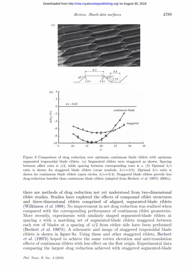
Figure 9. Comparison of drag reduction over optimum continuous blade riblets with optimumsegmented trapezoidal blade riblets. (a) Segmented riblets were staggered as shown. Spacingbetween offset rows is s/2, while spacing between corresponding rows is s. (b) Optimal h/sratio is shown for staggered blade riblets (cross symbols, h/s = 0.5). Optimal h/s ratio isshown for continuous blade riblets (open circles, h/s = 0.4). Staggered blade riblets provide lessdrag-reduction benefits than continuous blade riblets (adapted from Bechert et al. 1997b, 2000a).
there are methods of drag reduction not yet understood from two-dimensionalriblet studies. Studies have explored the effects of compound riblet structuresand three-dimensional riblets comprised of aligned, segmented-blade riblets(Wilkinson et al. 1988). No improvement in net drag reduction was realized whencompared with the corresponding performance of continuous riblet geometries.More recently, experiments with similarly shaped segmented-blade riblets atspacing s with a matching set of segmented-blade riblets staggered betweeneach row of blades at a spacing of s/2 from either side have been performed(Bechert et al. 1997b). A schematic and image of staggered trapezoidal bladeriblets is shown in figure 9a. Using these and other staggered riblets, Bechertet al. (1997b) hoped to achieve the same vortex elevation and anti-translationeffects of continuous riblets with less effect on the flow origin. Experimental datacomparing the largest drag reduction achieved with staggered segmented-blade
Phil. Trans. R. Soc. A (2010)
on August 30, 2018http://rsta.royalsocietypublishing.org/Downloaded from

4790 B. Dean and B. Bhushan
riblets to optimum continuous blade riblets can be seen in figure 9b. Again,no net benefit in drag reduction was achieved, and after comparison ofdata, the conclusion was made that it is unlikely that three-dimensionalriblets comprised of segmented two-dimensional riblets will greatly outperformcontinuous two-dimensional riblets.
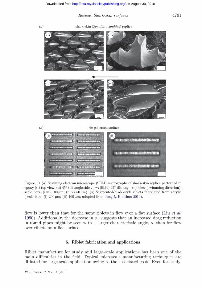
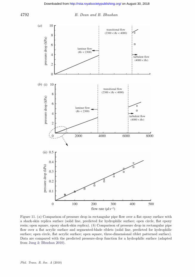
In the true three-dimensional realm, it has been theorized for some timethat scales on which shark-skin riblets are commonly grouped contribute to theperformance of some shark-skin varieties. By creating a pressure-exchange systembelow the scale surface, it was theorized that injection methods may have apressure-streak cancellation effect in the viscous sublayer, but concluded that theincreased momentum exchange created would have deleterious effects (Wilkinson1983; Bechert & Hoppe 1985; Bechert et al. 1986). More recently, there havebeen studies that have investigated the drag-reduction properties of riblet-toppedshark scales as both a static structure (Jung & Bhushan 2010) and a flexible—possibly controllable—member (Lang et al. 2008). Using the scales mouldedin epoxy resin from the skin of the Spiny dogfish (Squalus acanthias), shownin figure 10a, Jung & Bhushan (2010) have achieved a decrease in pressuredrop—corresponding to a decrease in fluid drag—versus a smooth surface in arectangular flow-cell flow experiment. Pressure drop from inlet to outlet of apipe is a measure of drag, with a large pressure drop occurring as a result ofhigh drag. In addition to the first study, a minimal decrease in pressure dropwas realized in a similar experiment using segmented aligned riblets fabricatedon acrylic (figure 10b) compared with a smooth acrylic test section. Resultsof the moulded epoxy scale study are shown in figure 11a, and results fromthe segmented-blade riblet study are shown in figure 11b. Certain sharks areknown to exhibit riblet-topped scales that are attached somewhat flexibly tothe underlying surface of the shark skin. These scales are able to change theirpitch angle by bristling. As the pressure beneath the scale attachments changes,the flexible member changes position, and the trailing edge of the scales canlift up. Alternatively, the scales may bristle at concave skin locations that occurduring the natural swimming. In an experiment simulating the bristling of flexibleriblet covered scales into the boundary layer as a possible mechanism of controland drag reduction, no drag-reduction benefit was achieved through extremescale bristling. However, notable flow phenomena were found to occur as aresult of scale bristling, including the formation of three distinct vortex shapes(Lang et al. 2008).
(c) Riblet trends in pipe flow
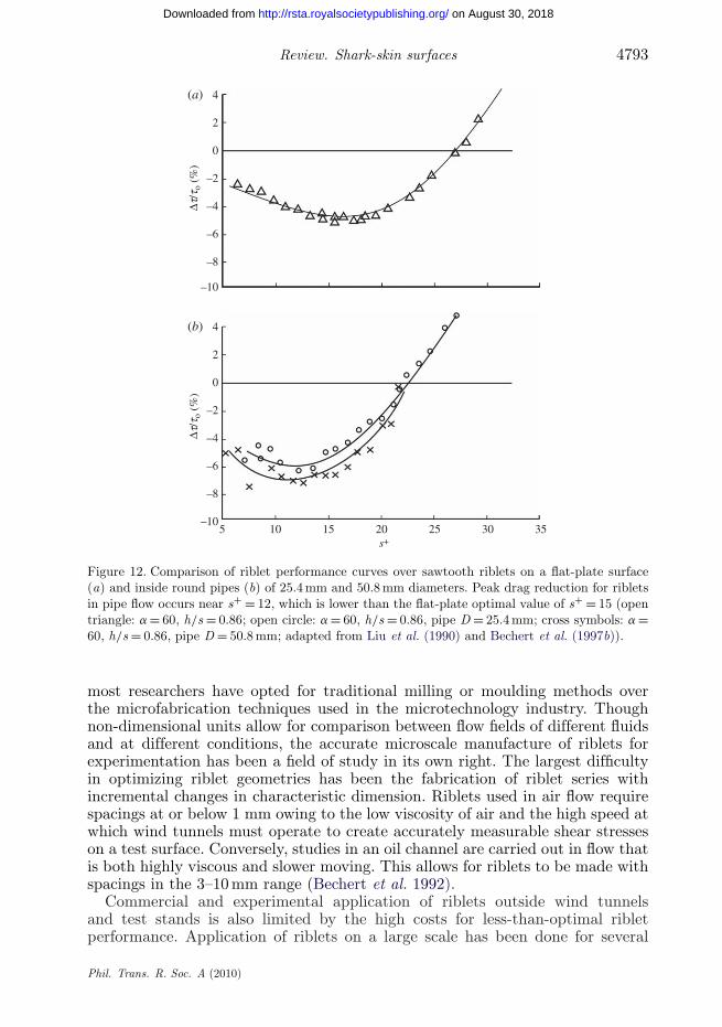
Riblet effects in pipe flow have been studied as well, and general patterns existin the drag-reduction benefit of sawtooth riblets. Due to the difficulty of ribletapplication in pipes, data are generally limited to applications of sawtooth-ribletfilm produced by 3M (Liu et al. 1990; Rohr et al. 1992). Drag-reduction tests inpipe flow are carried out by comparing the pressure drop in a riblet-lined pipe withthat of a similar pipe with a smooth surface. Drag-reduction data for sawtoothriblets on a flat plate are shown in figure 12a, and drag-reduction data for waterflow in sawtooth-riblet-lined pipes are shown in figure 12b. As riblets are appliedto the inside surface of a pipe, the riblet tips are shifted together owing to thecurve of the pipe wall. Consequently, the optimized s+ range for riblets in pipe
Phil. Trans. R. Soc. A (2010)
on August 30, 2018http://rsta.royalsocietypublishing.org/Downloaded from
Review. Shark-skin surfaces 4791
shark-skin (Squalus acanthias) replica
rib-patterned surface
(a)
(b)
(i) (ii)
(i) (ii)
(iii) (iv)
Figure 10. (a) Scanning electron microscope (SEM) micrographs of shark-skin replica patterned inepoxy ((i) top view; (ii) 45◦ tilt-angle side view; (iii,iv) 45◦ tilt-angle top view (swimming direction);scale bars, (i,iii) 100 mm; (ii,iv) 50 mm). (b) Segmented-blade-style riblets fabricated from acrylic(scale bars, (i) 200 mm; (ii) 100 mm; adapted from Jung & Bhushan 2010).
flow is lower than that for the same riblets in flow over a flat surface (Liu et al.1990). Additionally, the decrease in s+ suggests that an increased drag reductionin round pipes might be seen with a larger characteristic angle, a, than for flowover riblets on a flat surface.
5. Riblet fabrication and applications
Riblet manufacture for study and large-scale applications has been one of themain difficulties in the field. Typical microscale manufacturing techniques areill-fitted for large-scale application owing to the associated costs. Even for study,
Phil. Trans. R. Soc. A (2010)
on August 30, 2018http://rsta.royalsocietypublishing.org/Downloaded from
4792 B. Dean and B. Bhushan
10
(i)
(ii)
(a)
(b)
8
6pr
essu
re d
rop
(kPa
)
4
2
0
10
8
6
pres
sure
dro
p (k
Pa)
pres
sure
dro
p (k
Pa)
4
2
0
0.5
0.4
0.3
0.2
0.1
0 100 200 300 400 500
transitional flow(2300 < Re < 4000)
transitional flow(2300 < Re < 4000)
turbulent flow(4000 < Re)
turbulent flow(4000 < Re)
laminar flow(Re < 2300)
laminar flow(Re < 2300)
2000 4000 6000 8000
flow rate (µl s–1)
Figure 11. (a) Comparison of pressure drop in rectangular pipe flow over a flat epoxy surface witha shark-skin replica surface (solid line, predicted for hydrophilic surface; open circle, flat epoxyresin; open square, epoxy shark-skin replica). (b) Comparison of pressure drop in rectangular pipeflow over a flat acrylic surface and segmented-blade riblets (solid line, predicted for hydrophilicsurface; open circle, flat acrylic surface; open square, three-dimensional riblet patterned surface).Data are compared with the predicted pressure-drop function for a hydrophilic surface (adaptedfrom Jung & Bhushan 2010).
Phil. Trans. R. Soc. A (2010)
on August 30, 2018http://rsta.royalsocietypublishing.org/Downloaded from
Review. Shark-skin surfaces 4793
4
2
0
–2
Dt/t
o (%
)
–4
–6
–8
–10
4(a)
(b)
2
0
–2Dt
/to
(%)
–4
–6
–8
–10
5 10 15 20 25 30 35s+
Figure 12. Comparison of riblet performance curves over sawtooth riblets on a flat-plate surface(a) and inside round pipes (b) of 25.4 mm and 50.8 mm diameters. Peak drag reduction for ribletsin pipe flow occurs near s+ = 12, which is lower than the flat-plate optimal value of s+ = 15 (opentriangle: a = 60, h/s = 0.86; open circle: a = 60, h/s = 0.86, pipe D = 25.4 mm; cross symbols: a =60, h/s = 0.86, pipe D = 50.8 mm; adapted from Liu et al. (1990) and Bechert et al. (1997b)).
most researchers have opted for traditional milling or moulding methods overthe microfabrication techniques used in the microtechnology industry. Thoughnon-dimensional units allow for comparison between flow fields of different fluidsand at different conditions, the accurate microscale manufacture of riblets forexperimentation has been a field of study in its own right. The largest difficultyin optimizing riblet geometries has been the fabrication of riblet series withincremental changes in characteristic dimension. Riblets used in air flow requirespacings at or below 1 mm owing to the low viscosity of air and the high speed atwhich wind tunnels must operate to create accurately measurable shear stresseson a test surface. Conversely, studies in an oil channel are carried out in flow thatis both highly viscous and slower moving. This allows for riblets to be made withspacings in the 3–10 mm range (Bechert et al. 1992).
Commercial and experimental application of riblets outside wind tunnelsand test stands is also limited by the high costs for less-than-optimal ribletperformance. Application of riblets on a large scale has been done for several
Phil. Trans. R. Soc. A (2010)
on August 30, 2018http://rsta.royalsocietypublishing.org/Downloaded from
4794 B. Dean and B. Bhushan
studies, as well as for competition and retail purposes. Sawtooth riblets on vinylfilms produced by 3M riblets have been applied on surfaces ranging from boathulls to airplanes. Racing swimsuits produced by Speedo and others also employ ariblet pattern on the surface to reduce drag during the streamline portion of eachlap of a race (Krieger 2004). Additionally, a novel surface-scratching techniquehas been applied to the inside surface of pipelines to create a faux-riblet surface(Weiss 1997).
(a) Riblet-dimension selection
Though the turbulent-flow regime is characterized by completely randomflow, the thickness of the viscous sublayer and the width of the streamwisevortices—and therefore the optimal riblet spacing—is dependent on propertiesof the fluid flow. Riblet spacing is the basis of other riblet dimensions, so thecalculation of proper spacing is critical in riblet design. To calculate ribletspacing, wall shear stress must be known. Approximation of wall shear stressin rectangular channels can be done by combining the Blasius law for the frictioncoefficient with the Fanning friction factor and solving for wall shear stress.The Blasius law for the friction coefficient is defined as cf = 0.0791(Vd/n)−1/4,where n is the kinematic viscosity and d = 4A/p the hydraulic diameter ofthe channel, where A is the cross-sectional area and p the wetted perimeter.The Fanning friction factor is a dimensionless number defined as cf = 2t0/rV 2,where t0 is the wall shear stress, r the fluid density and V the averageflow velocity. Combining equations, wall shear stress can be approximatedby t0 = 0.03955 n1/4rV 7/4d−1/4.
Using the optimization comparison data in figure 7a, we know that a non-dimensionalized spacing should be chosen in the range 15 < s+ < 18. It is ourrecommendation that s+ values for pipe flow be chosen slightly low, in the range12 < s+ < 14, as shown in figure 12. To calculate physical spacing, s, from s+, thenon-dimensionalization factor, is used such that s = s+n/Vt, where Vt = (t0/r)0.5
is the wall stress velocity. Using the optimization curves for each riblet shape infigure 6, the optimal spacing-based characteristic dimensions can be used to solvefor optimal physical riblet dimensions.
(b) Application of riblets for drag reduction
The transition between research and application of technologies is often slow,and riblet surfaces have been no different. Because of the limitations of pastriblet technologies, both benefit in commercial applications and the methodsof application have been limited. Because riblets provide drag reduction onobjects where the dominant form of drag is caused by turbulent flow at thesurface, only objects of a certain form factor will show any measurable benefit.A large portion of the total drag on long objects with relatively flat sidesusually comes from turbulence at the wall, so riblets will have an appreciableeffect. However, for objects like automobiles, where pressure drag or flowseparation is the dominant form of drag, application of riblets would haveminimal effect.
Beginning in the mid-1980s, vinyl-film sawtooth riblets have been applied toboat hulls for racing. Both an Olympic rowing boat and an Americas Cup sailingyacht have been covered with riblets during competition. Riblets have also been
Phil. Trans. R. Soc. A (2010)
on August 30, 2018http://rsta.royalsocietypublishing.org/Downloaded from
Review. Shark-skin surfaces 4795
used on hulls of ships. Because skin friction of an aeroplane accounts for as muchas 48 per cent of total drag, various studies to incorporate riblet structureson aircraft surfaces have been carried out at the National Aeronautics andSpace Administration’s Langley Research Center (USA) in the 1970s (Walsh &Anders 1989) and later at the German Aerospace Center (Bechert et al. 1997a).Vinyl-film riblets have also been applied to test planes of both Boeing andAirbus. These films have not seen use on standard commercial flights yet, butthe benefits seen in testing should not go unmentioned. Application of ribletsto an aeroplane requires that several concessions are made. Several locationsthat would be covered by riblets must be left uncovered owing to environmentalfactors; windows are not covered for the sake of visibility, several locations wheredust and debris contacts the airplane during flight are left bare because the ribletswould be eroded during flight, and locations where de-icing, fuel or hydraulicfluid would come in contact with the riblets are left bare. After these concessions,the riblets covering the remaining 70 per cent of the aircraft have provided 3per cent total drag reduction. This 3 per cent drag reduction correlates to asimilar 3 per cent savings in fuel costs (Bechert et al. 1997a). Another potentialapplication of riblet structures in aeroplanes is on jet-engine blades to reduceskin friction.
Another large commercial application for riblet technologies is drag reductionin pipe flow. Machining the surface or applying vinyl-film riblets proves difficult inthe confines of most pipes, and an alternate solution must be used. Experimentalapplication of a scratching technique to the inside surface of pipes has createda riblet-like roughness that has provided more than 5 per cent drag-reductionbenefit (Weiss 1997). Stemming from an old sailors’ belief that ships sail fasterwhen their hulls are sanded in the longitudinal direction, Weiss fabricated theseriblets by using a steel brush moved through the pipeline to create a ridgedsurface. Studies have shown as much as a 10 per cent reduction in fluid flowwith the combined effect of cleaning the pipe and ridging the surface. Testson a 16 km gas-pipeline section have confirmed this benefit during commercialoperation (Bechert et al. 1997a).
The dominant and perhaps only commercial market where riblet technology fordrag reduction is commercially sold is competitive swimwear (Matthews 2008).The general population became aware of shark-skin’s drag-reduction benefitswith the introduction of the Fastskin suits by Speedo in 2004. Speedo claimed adrag reduction of several percent in a static test compared with other race suits.However, given the compromises of riblet geometry made during manufacturing,it is hard to believe the full extent of the drag reduction.
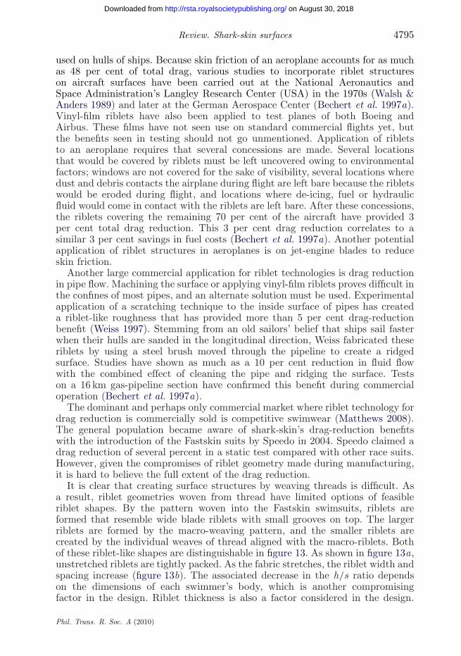
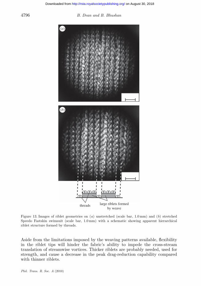
It is clear that creating surface structures by weaving threads is difficult. Asa result, riblet geometries woven from thread have limited options of feasibleriblet shapes. By the pattern woven into the Fastskin swimsuits, riblets areformed that resemble wide blade riblets with small grooves on top. The largerriblets are formed by the macro-weaving pattern, and the smaller riblets arecreated by the individual weaves of thread aligned with the macro-riblets. Bothof these riblet-like shapes are distinguishable in figure 13. As shown in figure 13a,unstretched riblets are tightly packed. As the fabric stretches, the riblet width andspacing increase (figure 13b). The associated decrease in the h/s ratio dependson the dimensions of each swimmer’s body, which is another compromisingfactor in the design. Riblet thickness is also a factor considered in the design.
Phil. Trans. R. Soc. A (2010)
on August 30, 2018http://rsta.royalsocietypublishing.org/Downloaded from
4796 B. Dean and B. Bhushan
threads large riblets formedby weave
(a)
(b)
Figure 13. Images of riblet geometries on (a) unstretched (scale bar, 1.0 mm) and (b) stretchedSpeedo Fastskin swimsuit (scale bar, 1.0 mm) with a schematic showing apparent hierarchicalriblet structure formed by threads.
Aside from the limitations imposed by the weaving patterns available, flexibilityin the riblet tips will hinder the fabric’s ability to impede the cross-streamtranslation of streamwise vortices. Thicker riblets are probably needed, used forstrength, and cause a decrease in the peak drag-reduction capability comparedwith thinner riblets.
Phil. Trans. R. Soc. A (2010)
on August 30, 2018http://rsta.royalsocietypublishing.org/Downloaded from
Review. Shark-skin surfaces 4797
(c) Riblet-fabrication methods for study and applications
For experimentation, many riblet geometries have been made through carefulmachining of riblets from stock, but standard machining techniques lack theprecision required to make riblets for use in high-speed air flow. Additionally,machining lacks the flexibility to fabricate small-scale riblets with enoughresolution to create incrementally different samples for true optimization ofsawtooth and scalloped riblets. Using a small-scale computer numericallycontrolled (CNC) mill, segmented-blade riblets have been fabricated in acrylicwith a thickness of only 38 mm and a height of 90 mm (Jung & Bhushan 2010).Scalloped and sawtooth riblets have been machined in aluminium at spacings inthe sub-millimetre range (Walsh & Lindemann 1984).
Another method used to construct blade riblets is to assemble separatelyfabricated parts. By fabricating thin element blades and spacers, stackedassemblies with adjustable geometry were created (Bechert et al. 1997b). Bymanufacturing blades in this separate manner, thinner blades can be fabricatedusing rolling techniques that eliminate the concern of milling errors ruining testplates. Riblet spacing is controlled by the added tolerances of each blade andspacer, which allows for an increase in overall fabrication tolerance. The majoradvantages of this method of assembly are ease of adjustment and less danger ofmilling errors destroying test plates. Optical images of assembled riblets can beseen in figure 9a.
For scale replicas and three-dimensional riblets, the complex shapes requiredusually afford moulding as the fabrication method. Micro-moulding and micro-embossing have been evaluated using polymethyl methacrylate (PMMA) as themould material and a silicone rubber as the replica material (Xin & Zhang 2008).Replicas were shown to lack resolution by 2.2 and 5.5 per cent of the groovespacing and 8.3 and 5.9 per cent of the height, respectively. Alternatively, epoxyreplicas of shark skin have been moulded in dental-wax reliefs taken from sharkskin and studied in flow-cell experiments in a rectangular pipe section (Jung &Bhushan 2010). Scanning electron microscope (SEM) images of these replicas canbe seen in figure 10a.
Many of these fabrication methods are not suitable for use outside laboratorysettings. The wear experienced in a physical environment where riblets wouldprovide measurable drag benefits would quickly render many of the above modelsnon-beneficial. Additionally, fabrication for application on a large scale is aconcern with most of these methods. Other methods of riblet manufacturinghave been studied for use in production environments. 3M vinyl-film ribletshave been used in myriad riblet-performance studies, and the fabricationof riblets by micro-profile grinding and incremental rolling processes havebeen investigated.
3M vinyl-film riblets (Marentic & Morris 1992) have been applied to manytest surfaces, including the inner sides of various pipes for pipe-flow studies(Koury & Virk 1995), flat plates in flow channels and wind tunnels, boat hulls intowing tanks (Choi et al. 1989), aeroplane wings (Han et al. 2002) and aeroplanefuselages. Similar riblet films have been fabricated using bulk micro-machiningof silicon to create a master for moulding of polydimethylsiloxane (PDMS) tocreate a thin, flexible riblet film. This film has been used in flow-visualizationtests (Lee & Choi 2008).
Phil. Trans. R. Soc. A (2010)
on August 30, 2018http://rsta.royalsocietypublishing.org/Downloaded from
4798 B. Dean and B. Bhushan
Grinding and rolling methods of riblet fabrication have been studied forapplication in both research and large-scale application. A profiled grinding wheelhas been used to fabricate several riblet geometries based on sawtooth ribletswith h = 20 mm and s = 50 mm (Denkena et al. 2009). Dressing of the grindingwheel was done with a diamond-profile roller used in a two-step process in whichthe profile roller dresses every second tooth on the first pass, shifts axially thedistance of one riblet spacing and dresses the remaining teeth on a second pass.One downside of the grinding process is the lack of hardening on the final ribletsurface. Alternatively, rolling methods can be used to strain harden the ribletsduring fabrication. Using a roller with the profile of two riblets on its outer face,a linearly patterned rolling process has been used to fabricate scalloped ribletsin a titanium alloy with h = 162 mm and s = 340 mm (Klocke et al. 2007). Thestrain hardening, favourable grain patterns and residual compressive stressesin the riblet surface after fabrication provide advantages in riblet strength forproduction applications.
6. Effect of slip length and polymer additives on fluid drag
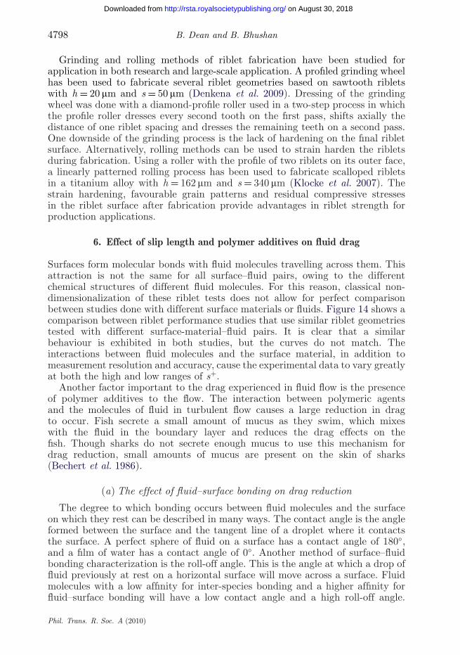
Surfaces form molecular bonds with fluid molecules travelling across them. Thisattraction is not the same for all surface–fluid pairs, owing to the differentchemical structures of different fluid molecules. For this reason, classical non-dimensionalization of these riblet tests does not allow for perfect comparisonbetween studies done with different surface materials or fluids. Figure 14 shows acomparison between riblet performance studies that use similar riblet geometriestested with different surface-material–fluid pairs. It is clear that a similarbehaviour is exhibited in both studies, but the curves do not match. Theinteractions between fluid molecules and the surface material, in addition tomeasurement resolution and accuracy, cause the experimental data to vary greatlyat both the high and low ranges of s+.
Another factor important to the drag experienced in fluid flow is the presenceof polymer additives to the flow. The interaction between polymeric agentsand the molecules of fluid in turbulent flow causes a large reduction in dragto occur. Fish secrete a small amount of mucus as they swim, which mixeswith the fluid in the boundary layer and reduces the drag effects on thefish. Though sharks do not secrete enough mucus to use this mechanism fordrag reduction, small amounts of mucus are present on the skin of sharks(Bechert et al. 1986).
(a) The effect of fluid–surface bonding on drag reduction
The degree to which bonding occurs between fluid molecules and the surfaceon which they rest can be described in many ways. The contact angle is the angleformed between the surface and the tangent line of a droplet where it contactsthe surface. A perfect sphere of fluid on a surface has a contact angle of 180◦,and a film of water has a contact angle of 0◦. Another method of surface–fluidbonding characterization is the roll-off angle. This is the angle at which a drop offluid previously at rest on a horizontal surface will move across a surface. Fluidmolecules with a low affinity for inter-species bonding and a higher affinity forfluid–surface bonding will have a low contact angle and a high roll-off angle.
Phil. Trans. R. Soc. A (2010)
on August 30, 2018http://rsta.royalsocietypublishing.org/Downloaded from
Review. Shark-skin surfaces 4799
Dt/t
o (%
)
–10
–5
0
5
10
15
5 10 15 20 25 30 35
s+
Figure 14. Comparison of drag reduction with oil (open squares) and air (open circles) on similarscalloped surfaces with h/s = 0.5 (adapted from Walsh (1982) and Bechert et al. (1997b)).
Fluids that have higher strength inter-species bonds than fluid–surface bondswill have high contact angles and low roll-off angles. The differences between thesurface energy of the fluid molecules and the surface material alter the bondingtendencies. A surface that has lower surface energy than the fluid flowing over itwill be less likely to bond with the fluid than a surface that has higher surfaceenergy than the fluid above it. Two common fluids whose surface attractionproperties are studied are water and oil. A surface that forms a contact angle withwater less than 90◦ is said to be hydrophilic (water loving). If the same interfacehas a contact angle greater than 90◦, it is said to be hydrophobic (water fearing).Surfaces with a contact angle greater than 150◦ are said to be superhydrophobic.To achieve superhydrophobicity, surface roughness must be applied in additionto typical material coatings. Surfaces that have the same contact-angle regimeswhen exposed to oil are said to be oleophilic, oleophobic or superoleophobic.
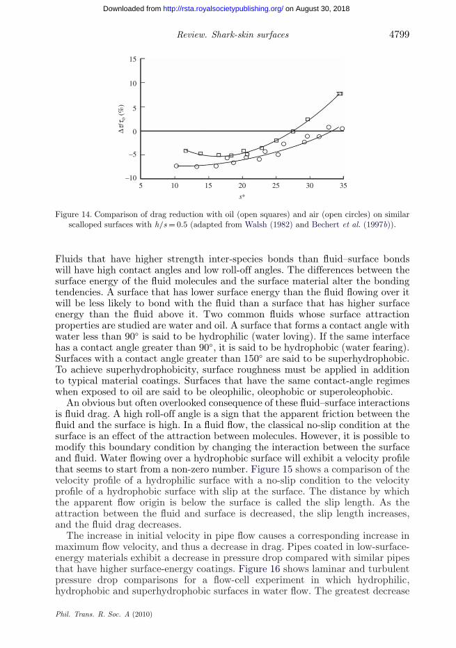
An obvious but often overlooked consequence of these fluid–surface interactionsis fluid drag. A high roll-off angle is a sign that the apparent friction between thefluid and the surface is high. In a fluid flow, the classical no-slip condition at thesurface is an effect of the attraction between molecules. However, it is possible tomodify this boundary condition by changing the interaction between the surfaceand fluid. Water flowing over a hydrophobic surface will exhibit a velocity profilethat seems to start from a non-zero number. Figure 15 shows a comparison of thevelocity profile of a hydrophilic surface with a no-slip condition to the velocityprofile of a hydrophobic surface with slip at the surface. The distance by whichthe apparent flow origin is below the surface is called the slip length. As theattraction between the fluid and surface is decreased, the slip length increases,and the fluid drag decreases.
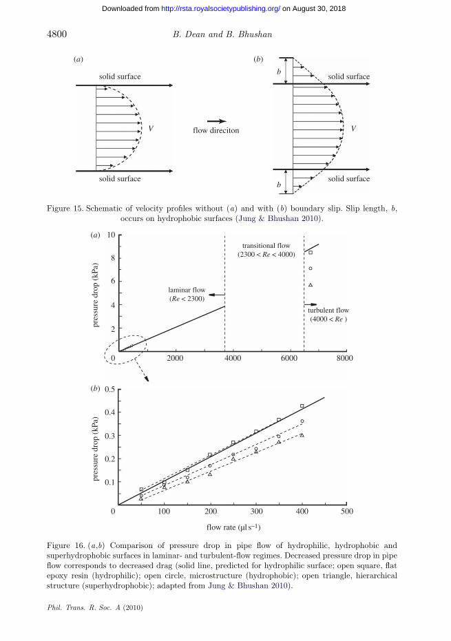
The increase in initial velocity in pipe flow causes a corresponding increase inmaximum flow velocity, and thus a decrease in drag. Pipes coated in low-surface-energy materials exhibit a decrease in pressure drop compared with similar pipesthat have higher surface-energy coatings. Figure 16 shows laminar and turbulentpressure drop comparisons for a flow-cell experiment in which hydrophilic,hydrophobic and superhydrophobic surfaces in water flow. The greatest decrease
Phil. Trans. R. Soc. A (2010)
on August 30, 2018http://rsta.royalsocietypublishing.org/Downloaded from
4800 B. Dean and B. Bhushan
flow direciton
solid surface
(a) (b)
V
b
b
V
solid surface solid surface
solid surface
Figure 15. Schematic of velocity profiles without (a) and with (b) boundary slip. Slip length, b,occurs on hydrophobic surfaces (Jung & Bhushan 2010).
4
6
8
pres
sure
dro
p (k
Pa)
pres
sure
dro
p (k
Pa)
10(a)
(b)
2
0.5
0.4
0.3
0.2
0.1
0 100 200 300 400 500
0 2000
laminar flow(Re < 2300)
transitional flow(2300 < Re < 4000)
turbulent flow(4000 < Re )
4000 6000
flow rate (µl s–1)
8000
Figure 16. (a,b) Comparison of pressure drop in pipe flow of hydrophilic, hydrophobic andsuperhydrophobic surfaces in laminar- and turbulent-flow regimes. Decreased pressure drop in pipeflow corresponds to decreased drag (solid line, predicted for hydrophilic surface; open square, flatepoxy resin (hydrophilic); open circle, microstructure (hydrophobic); open triangle, hierarchicalstructure (superhydrophobic); adapted from Jung & Bhushan 2010).
Phil. Trans. R. Soc. A (2010)
on August 30, 2018http://rsta.royalsocietypublishing.org/Downloaded from
Review. Shark-skin surfaces 4801
in pressure drop and fluid drag happens for the superhydrophobic surface,on which a slip length of up to 100 mm was calculated (Ou et al. 2004;Jung & Bhushan 2010). This behaviour is similar for interactions between otherfluid–surface pairs. Reducing the strength of bonding between the fluid moleculesand the surface causes a corresponding reduction in fluid drag in both the laminarand turbulent regimes.
(b) Effect of fish mucus and polymers on fluid drag
Fish are known to secrete mucus during swimming. Though it is not knownwhether the mucus is present at all times, it is known that certain environmentalfactors cause, alter or enhance the production of mucus. These environmentalstressors may present a need for increased swimming speed to catch or avoidbecoming prey, protection against non-predatory threats such as micro-organisms,or resist abrasion while swimming near rocky surfaces. Regardless of whichevents cause fish to secrete mucus, the drag-reduction benefits during mucus-assisted swimming are known. Numerous experiments have demonstrated thedrag reduction possible with fish-covered mucus compared with non-mucus-covered shapes (Hoyt 1975). In an experiment comparing the drag on wax modelsto a mucus-covered fish, a reduction in skin friction drag of 50 per cent was seen(Daniel 1981).
Similar to these fish-mucus experiments, polymer additives in pipe flowshave been known for many years to reduce the drag in fluid flows by extremeamounts. In a pipe-flow study comparing various injection techniques of polymersolutions into water, drag reductions of up to 80 per cent were achieved (Frings1988). Additionally, the drag-reduction benefit increases with increased Reynoldsnumber. While this works well for pipe flows, in which the polymer remains mixedand active throughout the length of the pipe, its application to external flows ismuch more difficult. Mucus on fish does not mix well with water in static contact,but does mix and provide drag reduction during dynamic contact. By this feature,the mucus use of fish is minimized. Unfortunately, for any long-range applicationof polymer drag reduction on an external flow, the polymer solution must becontinuously injected. This would cause large quantities of the solution to beused and probably render the strategy inefficient in terms of overall energy use.
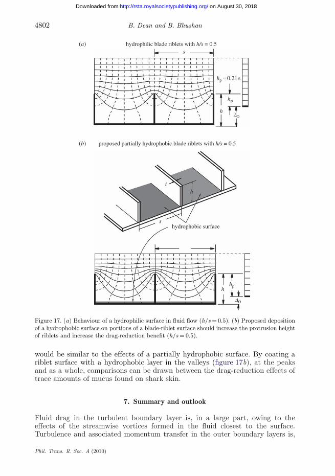
Though sharks do not secrete enough mucus to use this mechanism for dragreduction, small amounts of mucus are present on the skin of sharks (Bechertet al. 1986). It is possible that shark-skin mucus secretion is similar to fish, whereonly environmental stressors or swimming cause an increase in output, but thetotal quantity of mucus on the surface at any given time is probably quite low.One possible mechanism by which this trace quantity of mucus could be usefulis in changing the flow characteristics in the riblet valleys or at the riblet peaks,where shear stresses are highest. In the riblet valleys, a trace secretion of mucuscould increase flow velocity and decrease the overall momentum transfer from theshark to the surrounding water by condensing the overall structure of the velocitygradient. Alternatively, injection at the riblet peaks may cause a reduction inshear stresses where they are at their maximum and again cause a reduction indrag. These small effects near the surface may propagate into a larger benefit asthe lines of constant velocity in the flow shift and condense, as shown speculativelyin figure 17. The localized effect of mucus secretion in the valleys or at the peaks
Phil. Trans. R. Soc. A (2010)
on August 30, 2018http://rsta.royalsocietypublishing.org/Downloaded from
4802 B. Dean and B. Bhushan
hydrophilic blade riblets with h/s = 0.5
proposed partially hydrophobic blade riblets with h/s = 0.5
hydrophobic surface
s
hp ≈ 0.21 s
hp
hDO
hph
s
t
h
DO
(a)
(b)
Figure 17. (a) Behaviour of a hydrophilic surface in fluid flow (h/s = 0.5). (b) Proposed depositionof a hydrophobic surface on portions of a blade-riblet surface should increase the protrusion heightof riblets and increase the drag-reduction benefit (h/s = 0.5).
would be similar to the effects of a partially hydrophobic surface. By coating ariblet surface with a hydrophobic layer in the valleys (figure 17b), at the peaksand as a whole, comparisons can be drawn between the drag-reduction effects oftrace amounts of mucus found on shark skin.
7. Summary and outlook
Fluid drag in the turbulent boundary layer is, in a large part, owing to theeffects of the streamwise vortices formed in the fluid closest to the surface.Turbulence and associated momentum transfer in the outer boundary layers is,
Phil. Trans. R. Soc. A (2010)
on August 30, 2018http://rsta.royalsocietypublishing.org/Downloaded from
Review. Shark-skin surfaces 4803
in a large part, owing to the translation, ejection and twisting of these vortices.Additionally, the vortices also cause high velocities at the surface that create largeshear stresses on the surface. Numerical simulation has supported riblet drag-reduction theories by showing two mechanisms of riblet drag reduction. First,riblets impede the translation of the streamwise vortices, which causes a reductionin vortex ejection and outer-layer turbulence. Second, riblets lift the vortices offthe surface and reduce the amount of surface area exposed to the high-velocityflow. By modifying the velocity distribution, riblets facilitate a net reduction inshear stress at the surface.
Various riblet shapes have been studied for their drag-reducing capabilities,but sawtooth, scalloped and blade riblets are most common. By varying flowproperties or riblet geometries, optimization studies have been performed. Dragreduction by riblet surfaces has been shown to be as high as nearly 10 percent given an optimal geometry of h/s ∼ 0.5 for blade riblets with a no-slipcondition. The maximum reliable drag reduction provided by scalloped ribletsand sawtooth riblets is about 6 per cent at h/s ∼ 0.7 and 5 per cent at a ∼ 60◦,respectively. Experimentation of other shapes has provided similar benefits ofaround 5 per cent drag reduction. Additional experimentation with simplethree-dimensional shapes, such as offset segmented-blade riblets, has shown acomparable performance to standard-blade riblets, but hierarchical structuresand complex three-dimensional shapes have yet to show improved benefits. Thebehaviour of static and dynamic versions of complex three-dimensional replicashas been minimally investigated, and much work remains in understanding thecomplexities that are involved. To date, no improved drag reduction has beenaccomplished using replica models, but hypothesized control mechanisms fordynamic replicas have been proposed. Though the optimum shape for drag-reduction performance is blade riblets, the fragile nature of these blades makestheir commercial application of little use. Scalloped and sawtooth riblets, whichprovide considerably less drag-reduction benefits, are much stronger shapesmechanically speaking and should be used for application in environments wherecontact may occur with non-fluid materials.
Commercial applications of riblets include competition swimsuits, whichuse a thread-based riblet geometry, as well as experimental applications toaeroplanes. Drag reductions in riblet application have been accomplished, andflight applications have seen a fuel saving of as much as 3 per cent. Manufacturingtechniques for riblets must also be chosen specific to their application. Vinyl-filmriblets are the easiest method, as application of a film to a surface requires lessfor work small-scale application than other methods. Rolling or grinding methodsof riblet application should be investigated for turbine blades or high-volumecommercially sold pieces. Machining methods are unfavourable in most instances,and should be avoided in most instances of non-research riblet application.
The future of riblet research is two-fold. The investigation of both static anddynamic riblet-topped scales, as well as partially-to-fully fluid-bond-resistantriblet surfaces must be investigated. Application of superhydrophobic surfacesto riblet geometries should be investigated in a flow-cell experiment usingwater to study the effects of localized hydrophobicity on water flow overriblets. We expect that a notable increase in drag reduction will be seenusing a biomimetic application of hydrophobic surfaces at the riblet valleys,the riblet peaks, or alternatively across the entire surface. Additionally, atomic
Phil. Trans. R. Soc. A (2010)
on August 30, 2018http://rsta.royalsocietypublishing.org/Downloaded from
4804 B. Dean and B. Bhushan
force microscope studies of the nanoscale surface characteristics on shark skinshould be done to investigate the possibility of nano-roughness improving theoverall hydrophobicity of the shark-skin surface. We expect that in combinationand separate, the mucus and surface-roughness characteristics of the sharkskin will provide increased drag-reduction benefits compared with currentfabricated surfaces.
References
Bechert, D. W. & Hoppe, G., 1985 On the drag reduction of the shark skin. In AIAA Shear FlowControl Conf., Boulder, CO, 12–14 March, paper no. AIAA-85-0564.
Bechert, D. W., Bartenwerfer, M., Hoppe, G. & Reif, W.-E. 1986 Drag reduction mechanismsderived from shark skin. In Proc. 15th Int. Council of Aeronautical Sciences Congress, London,UK, 7–12 September, vol. 2, pp. 1044–1068, paper no. ICAS-86-1.8.3.
Bechert, D. W., Hoppe, G., van der Hoven, J. G. Th. & Makris, R. 1992 The Berlin oil channelfor drag reduction research. Exp. Fluids 12, 251–260. (doi:10.1007/BF00187303)
Bechert, D. W., Bruse, M., Hage, W. & Meyer, R. 1997a Biological surfaces and their technologicalapplication—laboratory and flight experiments on drag reduction and separation control. InAIAA 28th Fluid Dynamics Conference, Snowmass Village, CO, 29 June–2 August, paper no.AIAA-1997-1960.
Bechert, D. W., Bruse, M., Hage, W., van der Hoeven, J. G. T. & Hoppe, G. 1997b Experimentson drag reducing surfaces and their optimization with an adjustable geometry. J. Fluid Mech.338, 59–87. (doi:10.1017/S0022112096004673)
Bechert, D. W., Bruse, M. & Hage, W. 2000a Experiments with three-dimensional riblets as anidealized model of shark skin. Exp. Fluids 28, 403–412. (doi:10.1007/s003480050400)
Bechert, D. W., Bruse, M., Hage, W. & Meyer, R. 2000b Fluid mechanics of biological surfaces andtheir technological application. Naturwissenschaften 87, 157–171. (doi:10.1007/s001140050696)
Bhushan, B. 2007 Adhesion of multi-level hierarchical attachment systems in gecko feet. J. AdhesionSci. Technol. 21, 1213–1258. (doi:10.1163/156856107782328353)
Bhushan, B. 2008 Nanotribology and nanomechanics—an introduction, 2nd edn. Heidelberg,Germany: Springer.
Bhushan, B. 2009 Biomimetics: lessons from nature—an overview. Phil. Trans. R. Soc. A 367,1445–1486. (doi:10.1098/rsta.2009.0011)
Bhushan, B. 2010 Springer handbook of nanotechnology, 3rd edn. Heidelberg, Germany: Springer.(doi:10.1007/978-3-642-02525-9)
Bhushan, B. & Her, E. K. 2010 Fabrication of superhydrophobic surfaces with high and lowadhesion inspired from rose petal. Langmuir 26, 8207–8217. (doi:10.1021/la904585j)
Choi, K. S., Gadd, G. E., Pearcey, H. H., Savill, A. M. & Svensson, S. 1989 Tests of drag-reducingpolymer coated on a riblet surface. Appl. Sci. Res. 46, 209–216. (doi:10.1007/BF00404818)
Choi, K. S., Yang, X., Clayton, B. R., Glover, E. J., Altar, M., Semenov, B. N. & Kulik, V. M.1997 Turbulent drag reduction using compliant surfaces. Proc. R. Soc. A 453, 2229–2240.(doi:10.1098/rspa.1997.0119)
Coles, D. 1978 A model for flow in the viscous sublayer. In Proc. Workshop on Coherent Structureof Turbulent Boundary Layers, Bethlehem, PA, pp. 462–475.
Cutkosky, M. R. & Kim, S. 2009 Design and fabrication of multi-material structures for bioinspiredrobots. Phil. Trans. R. Soc. A 367, 1799–1813. (doi:10.1098/rsta.2009.0013)
Daniel, T. L. 1981 Fish mucus: in situ measurements of polymer drag reduction. Biol. Bull. 160,376–382. (doi:10.2307/1540846)
Denkena, B., de Leon, L. & Wang, B. 2009 Grinding of microstructured functional surfaces: a novelstrategy for dressing of microprofiles. Prod. Eng. 3, 41–48. (doi:10.1007/s11740-008-0134-0)
Frings, B. 1988 Heterogeneous drag reduction in turbulent pipe flows using various injectiontechniques. Rheologica Acta 27, 92–10. (doi:10.1007/BF01372455)
Phil. Trans. R. Soc. A (2010)
on August 30, 2018http://rsta.royalsocietypublishing.org/Downloaded from
Review. Shark-skin surfaces 4805
Goldstein, D., Handler, R. & Sirovich, L. 1995 Direct numerical simulation of turbulent flow over amodeled riblet covered surface. J. Fluid Mech. 302, 333–376. (doi:10.1017/S0022112095004125)
Gorb, S. 2001 Attachment devices of insect cuticles. Dordrecht, The Netherlands: Kluwer.Han, M., Huh, J. K., Lee, S. S. & Lee, S. 2002 Micro-riblet film for drag reduction. In Proc. Pacific
Rim Workshop on Transducers and Micro/Nano Technologies, Xiamen, China.Hoyt, J. W. 1975 Hydrodynamic drag reduction due to fish slimes. Swimming and Flying in
Nature 2, 653–672.Jung, Y. C. & Bhushan, B. 2010 Biomimetic structures for fluid drag reduction in laminar
and turbulent flows. J. Phys.: Condens. Matter 22, 035104. (doi:10.1088/0953-8984/22/3/035104)
Kline, S. J., Reynolds, W. C., Schraub, F. A. & Runstadler, P. W. 1967 The structure of turbulentboundary layers. J. Fluid Mech. 30, 741–773. (doi:10.1017/S0022112067001740)
Klocke, F., Feldhaus, B. & Mader, S. 2007 Development of an incremental rolling process forthe production of defined riblet surface structures. Prod. Eng. 1, 233–237. (doi:10.1007/s11740-007-0031-y)
Koury, E. & Virk, P. S. 1995 Drag reduction by polymer solutions in a riblet-lined pipe. Appl. Sci.Res. 54, 323–347. (doi:10.1007/BF00863517)
Krieger, K. 2004 Do pool sharks really swim faster? Science 305, 636–637. (doi:10.1126/science.305.5684.636)
Lang, A. W., Motta, P., Hidalgo, P. & Westcott, M. 2008 Bristled shark skin: a microgeometry forboundary layer control? Bioinspir. Biomim. 3, 1–9. (doi:10.1088/1748-3182/3/4/046005)
Lee, S. J. & Choi, Y. S. 2008 Decrement of spanwise vortices by a drag-reducing riblet surface. J.Turbul. 9, 1–15. (doi:10.1080/14685240802251517)
Lee, S.-J. & Lee, S.-H. 2001 Flow field analysis of a turbulent boundary layer over a riblet surface.Exp. Fluids 30, 153–166. (doi:10.1007/s003480000150)
Liu, K. N., Christodoulou, C., Riccius, O. & Joseph, D. D. 1990 Drag reduction in pipes lined withriblets. AIAA J. 28, 1697–1699. (doi:10.2514/3.10459)
Matthews, J. N. A. 2008 Low-drag suit propels swimmers. Physics Today, August, pp. 32–33.Marentic, F. J. & Morris, T. L. 1992 Drag reduction article. United States Patent no. 5 133 516.Munson, B., Young, D. & Okiishi, T. 2005 Fundamentals of fluid mechanics, 5th edn. New York,
NY: Wiley.Nosonovsky, M. & Bhushan, B. 2008 Multiscale dissipative mechanisms and hierarchical surfaces:
friction, superhydrophobicity, and biomimetics. Heidelberg, Germany: Springer.Ou, J., Perot, B. & Rothstein, J. P. 2004 Laminar drag reduction in microchannels using
ultrahydrophobic surfaces. Phys. Fluids 16, 4635–4643. (doi:10.1063/1.1812011)Reif, W.-E. 1985 Squamation and ecology of sharks, vol. 78, pp. 1–255. Frankfurt, Germany: Courier
Forschungsinstitut Senckenberg.Robinson, S. K. 1991 The kinematics of turbulent boundary layer structure. NASA TM 103859,
NASA, Washington, DC.Rohr, J. J., Anderson, G. W., Reidy, L. W. & Hendricks, E. W. 1992 A comparison of the drag-
reducing benefits of riblets in internal and external flows. Exp. Fluids 13, 361–368. (doi:10.1007/BF00223243)
Shephard, K. L. 1994 Functions for fish mucus. Rev. Fish Biol. Fish. 4, 401–429. (doi:10.1007/BF00042888)
Walsh, M. J. 1980 Drag characteristics of v-groove and transverse curvature riblets. Viscous FlowDrag Reduction 72, 169–184.
Walsh, M. J. 1982 Turbulent boundary layer drag reduction using riblets. In AIAA 20th AerospaceSciences Meeting, Orlando, FL, 11–14 January, paper no. AIAA-82-0169.
Walsh, M. J. & Anders, J. B. 1989 Riblet/LEBU research at NASA Langley. Appl. Sci. Res. 46,255–262. (doi:10.1007/BF00404822)
Walsh, M. J. & Lindemann, A. M. 1984 Optimization and application of riblets for turbulentdrag reduction. In AIAA 22nd Aerospace Sciences Meeting, Reno, NV, 9–12 January, paper no.AIAA-84-0347.
Weiss, M. H. 1997 Implementation of drag reduction techniques in natural gas pipelines. In 10thEuropean Drag Reduction Working Meeting, Berlin, Germany, 19–21 March.
Phil. Trans. R. Soc. A (2010)
on August 30, 2018http://rsta.royalsocietypublishing.org/Downloaded from

4806 B. Dean and B. Bhushan
Wilkinson, S. P. 1983 Influence of wall permeability on turbulent boundary-layer properties. In 21stAerospace Sciences Meeting of the American Institute of Aeronautics and Astronautics, Reno,NV, 10–13 January, paper no. AIAA 83-0294.
Wilkinson, S. P. & Lazos, B. S. 1987 Direct drag and hot-wire measurements on thin-element ribletarrays. In IUTAM Symposium on Turbulence Management and Relaminarization, Bangalore,India, 19–23 January.
Wilkinson, S. P., Anders, J. B., Lazos, B. S. & Bushnell, D. M. 1988 Turbulent drag reductionresearch at NASA Langley: progress and plans. Inter. J. Heat Fluid Flow 9, 266–277.(doi:10.1016/0142-727X(88)90037-9)
Xin, H. & Zhang, D. 2008 Study on the micro-replication of shark skin. Sci. China Ser. E: Technol.Sci. 51, 890–896. (doi:10.1007/s11431-008-0080-2)
Phil. Trans. R. Soc. A (2010)
on August 30, 2018http://rsta.royalsocietypublishing.org/Downloaded from
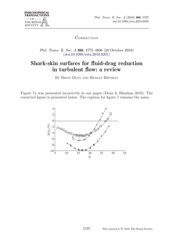
Phil. Trans. R. Soc. A (2010) 368, 5737doi:10.1098/rsta.2010.0294
CORRECTION
Phil. Trans. R. Soc. A 368, 4775–4806 (28 October 2010)(doi:10.1098/rsta.2010.0201)
Shark-skin surfaces for fluid-drag reductionin turbulent flow: a review
BY BRIAN DEAN AND BHARAT BHUSHAN
Figure 7a was presented incorrectly in our paper (Dean & Bhushan 2010). Thecorrected figure is presented below. The caption for figure 7 remains the same.
5–10
–8
–6
–4
–2
0
2
4
10 15 20S+
Dt/t
o (%
)
25 30 35
This journal is © 2010 The Royal Society5737


![[R1] Shark Skin Surfaces for Fluid Drag Reduction in Turbulent Flow](https://static.fdocuments.us/doc/165x107/577cc18e1a28aba71193594f/r1-shark-skin-surfaces-for-fluid-drag-reduction-in-turbulent-flow.jpg)