SМ_FTXS20-50G RXS20-50G_2008
320
SiBE04 - 808 [Applied Models] Inverter Pair : Cooling Only Inverter Pair : Heat Pump Inverter Pair Wall Mounted Type G-Series
-
Upload
emil-tashev -
Category
Documents
-
view
207 -
download
5
Transcript of SМ_FTXS20-50G RXS20-50G_2008
SiBE04 - 808
[Applied Models] Inverter Pair : Cooling Only Inverter Pair : Heat Pump
Inverter PairWall Mounted Type G-Series
SiBE04-808
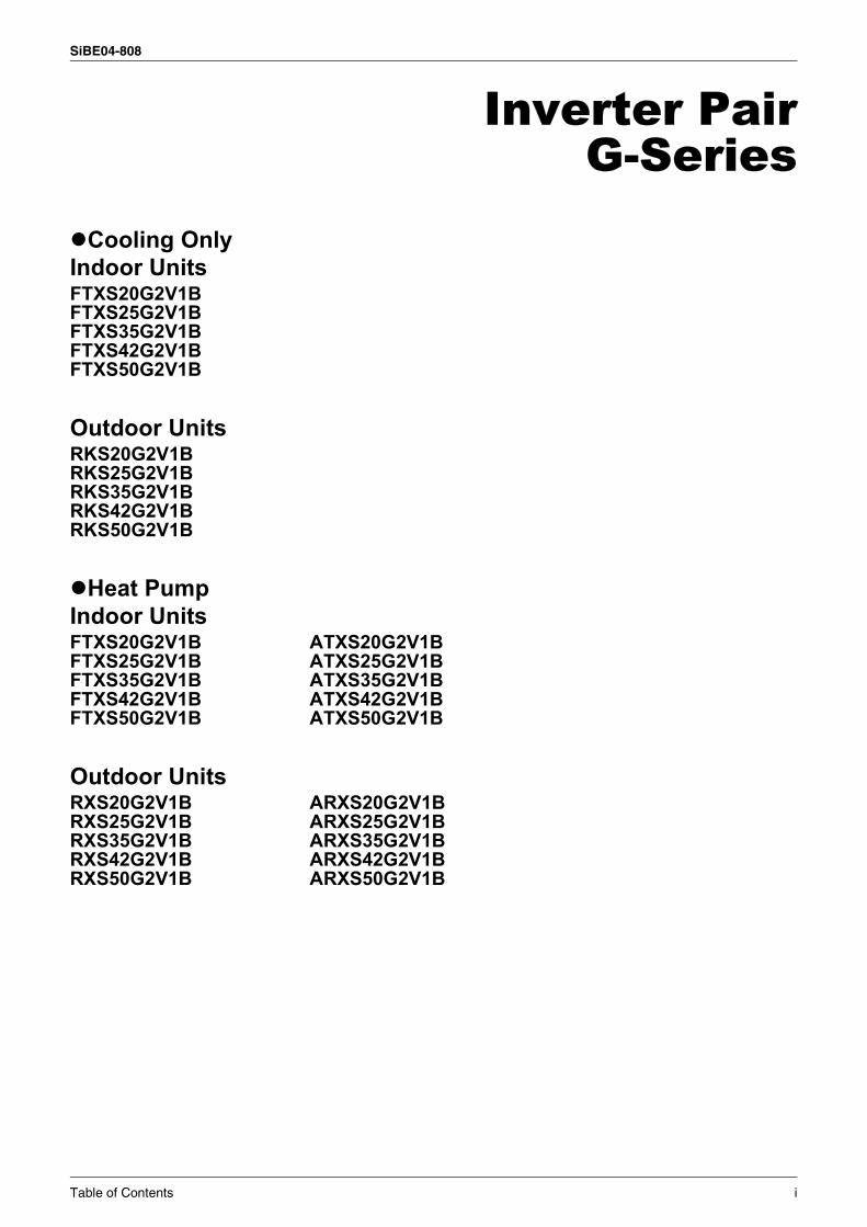
Inverter PairG-Series
Cooling OnlyIndoor UnitsFTXS20G2V1BFTXS25G2V1BFTXS35G2V1BFTXS42G2V1BFTXS50G2V1B
Outdoor UnitsRKS20G2V1BRKS25G2V1BRKS35G2V1BRKS42G2V1BRKS50G2V1B
Heat PumpIndoor UnitsFTXS20G2V1B ATXS20G2V1BFTXS25G2V1B ATXS25G2V1BFTXS35G2V1B ATXS35G2V1BFTXS42G2V1B ATXS42G2V1BFTXS50G2V1B ATXS50G2V1B
Outdoor UnitsRXS20G2V1B ARXS20G2V1BRXS25G2V1B ARXS25G2V1BRXS35G2V1B ARXS35G2V1BRXS42G2V1B ARXS42G2V1BRXS50G2V1B ARXS50G2V1B
Table of Contents i
SiBE04-808
1. Introduction .............................................................................................v1.1 Safety Cautions ........................................................................................v1.2 Used Icons .............................................................................................. ix
Part 1 List of Functions ................................................................11. List of Functions ......................................................................................2
Part 2 Specifications ....................................................................51. Specifications ..........................................................................................6
1.1 Cooling Only.............................................................................................61.2 Heat Pump ...............................................................................................8
Part 3 Printed Circuit Board Connector Wiring Diagram ...........151. Printed Circuit Board Connector Wiring Diagram..................................16
1.1 Indoor Unit..............................................................................................161.2 Outdoor Unit ...........................................................................................18
Part 4 Function and Control........................................................251. Main Functions......................................................................................26
1.1 Frequency Principle................................................................................261.2 Airflow Direction Control.........................................................................281.3 Fan Speed Control for Indoor Units........................................................291.4 Programme Dry Function .......................................................................301.5 Automatic Operation...............................................................................311.6 Thermostat Control.................................................................................321.7 NIGHT SET Mode ..................................................................................331.8 ECONO Mode ........................................................................................341.9 2 AREA INTELLIGENT EYE ..................................................................351.10 Inverter POWERFUL Operation .............................................................371.11 Other Functions......................................................................................38
2. Function of Thermistor ..........................................................................402.1 Heat Pump Model...................................................................................402.2 Cooling Only Model ................................................................................41
3. Control Specification .............................................................................423.1 Mode Hierarchy ......................................................................................423.2 Frequency Control..................................................................................433.3 Controls at Mode Changing / Start-up....................................................453.4 Discharge Pipe Temperature Control.....................................................483.5 Input Current Control..............................................................................493.6 Freeze-up Protection Control .................................................................503.7 Heating Peak-cut Control .......................................................................513.8 Fan Control.............................................................................................523.9 Liquid Compression Protection Function 2.............................................523.10 Defrost Control .......................................................................................523.11 Electronic Expansion Valve Control .......................................................553.12 Malfunctions ...........................................................................................583.13 Forced Operation Mode .........................................................................593.14 Additional Function.................................................................................603.15 Facility Setting Switch (cooling at low outdoor temperature)..................61
ii Table of Contents
SiBE04-808
Part 5 Operation Manual .............................................................631. System Configuration............................................................................642. Instruction..............................................................................................65
2.1 Safety Precautions .................................................................................652.2 FTXS20/25/35/42/50G2V1B...................................................................672.3 ATXS20/25/35/42/50G2V1B ..................................................................96
Part 6 Service Diagnosis...........................................................1211. Caution for Diagnosis..........................................................................1222. Problem Symptoms and Measures .....................................................1233. Service Check Function ......................................................................1244. Troubleshooting ..................................................................................127
4.1 Error Codes and Description ................................................................1274.2 Indoor Unit PCB Abnormality ...............................................................1284.3 Freeze-up Protection Control or High Pressure Control.......................1294.4 Fan Motor (DC Motor) or Related Abnormality.....................................1314.5 Thermistor or Related Abnormality (Indoor Unit)..................................1334.6 Signal Transmission Error (between Indoor and Outdoor Unit) ...........1344.7 Unspecified Voltage (between Indoor and Outdoor Units) ...................1354.8 Outdoor Unit PCB Abnormality.............................................................1364.9 OL Activation (Compressor Overload) .................................................1384.10 Compressor Lock .................................................................................1394.11 DC Fan Lock ........................................................................................1404.12 Input Over Current Detection ...............................................................1414.13 Four Way Valve Abnormality................................................................1444.14 Discharge Pipe Temperature Control...................................................1484.15 High Pressure Control in Cooling .........................................................1504.16 Compressor System Sensor Abnormality ............................................1524.17 Position Sensor Abnormality ................................................................1554.18 DC Voltage / Current Sensor Abnormality (20/25/35/42 Class) ...........1574.19 CT or Related Abnormality (50 Class)..................................................1584.20 Thermistor or Related Abnormality (Outdoor Unit)...............................1604.21 Electrical Box Temperature Rise..........................................................1624.22 Radiation Fin Temperature Rise ..........................................................1654.23 Output Over Current Detection.............................................................1714.24 Insufficient Gas.....................................................................................1734.25 Low-voltage Detection or Over-voltage Detection................................1774.26 Signal Transmission Error on Outdoor Unit PCB .................................179
5. Check ..................................................................................................1805.1 How to Check .......................................................................................180
Part 7 Removal Procedure ........................................................1911. Indoor Unit...........................................................................................192
1.1 Removal of Air filter ..............................................................................1921.2 Removal of Front Panel........................................................................1941.3 Removal of Front Grille ........................................................................1961.4 Removal of Horizontal Blades and Vertical Blades ..............................1991.5 Removal of Electrical Box ....................................................................2021.6 Removal of PCB...................................................................................205
Table of Contents iii
SiBE04-808
1.7 Removal of Heat Exchanger ................................................................2101.8 Removal of Fan Rotor ..........................................................................213
2. Outdoor Unit........................................................................................2192.1 20/25/35 Class .....................................................................................2192.2 42 Class ...............................................................................................2442.3 50 Class ...............................................................................................266
Part 8 Others .............................................................................2891. Others .................................................................................................290
1.1 Test Run from the Remote Controller ..................................................2901.2 Jumper Settings ...................................................................................2911.3 Application of Silicon Grease to a Power Transistor and
a Diode Bridge......................................................................................292
Part 9 Appendix.........................................................................2931. Piping Diagrams..................................................................................294
1.1 Indoor Units ..........................................................................................2941.2 Outdoor Units .......................................................................................295
2. Wiring Diagrams..................................................................................2992.1 Indoor Units ..........................................................................................2992.2 Outdoor Units .......................................................................................299
Index ............................................................................................. i
Drawings & Flow Charts ................................................................ v
iv Table of Contents
SiBE04-808 Introduction
1. Introduction1.1 Safety Cautions
Cautions and Warnings
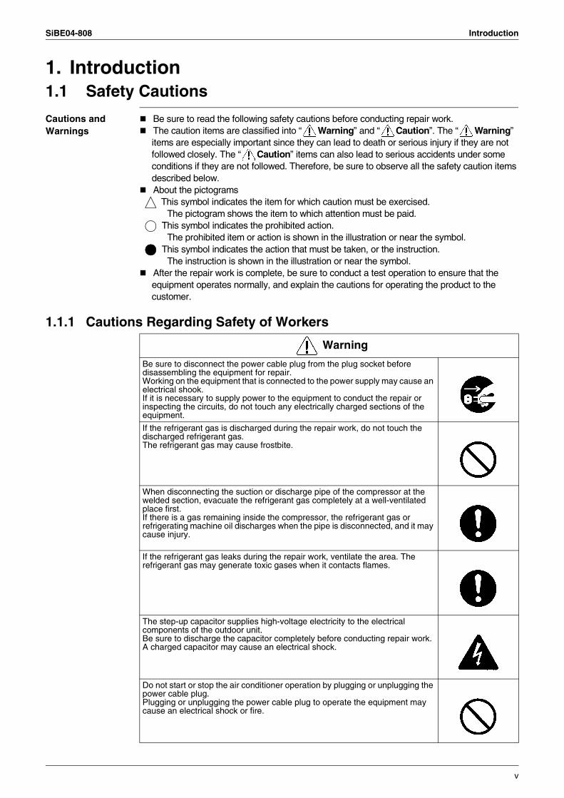
Be sure to read the following safety cautions before conducting repair work.The caution items are classified into “ Warning” and “ Caution”. The “ Warning” items are especially important since they can lead to death or serious injury if they are not followed closely. The “ Caution” items can also lead to serious accidents under some conditions if they are not followed. Therefore, be sure to observe all the safety caution items described below.About the pictograms
This symbol indicates the item for which caution must be exercised. The pictogram shows the item to which attention must be paid.
This symbol indicates the prohibited action. The prohibited item or action is shown in the illustration or near the symbol.
This symbol indicates the action that must be taken, or the instruction. The instruction is shown in the illustration or near the symbol.
After the repair work is complete, be sure to conduct a test operation to ensure that the equipment operates normally, and explain the cautions for operating the product to the customer.
1.1.1 Cautions Regarding Safety of Workers
Warning
Be sure to disconnect the power cable plug from the plug socket before disassembling the equipment for repair.Working on the equipment that is connected to the power supply may cause an electrical shook.If it is necessary to supply power to the equipment to conduct the repair or inspecting the circuits, do not touch any electrically charged sections of the equipment.
If the refrigerant gas is discharged during the repair work, do not touch the discharged refrigerant gas.The refrigerant gas may cause frostbite.
When disconnecting the suction or discharge pipe of the compressor at the welded section, evacuate the refrigerant gas completely at a well-ventilated place first.If there is a gas remaining inside the compressor, the refrigerant gas or refrigerating machine oil discharges when the pipe is disconnected, and it may cause injury.
If the refrigerant gas leaks during the repair work, ventilate the area. The refrigerant gas may generate toxic gases when it contacts flames.
The step-up capacitor supplies high-voltage electricity to the electrical components of the outdoor unit.Be sure to discharge the capacitor completely before conducting repair work.A charged capacitor may cause an electrical shock.
Do not start or stop the air conditioner operation by plugging or unplugging the power cable plug.Plugging or unplugging the power cable plug to operate the equipment may cause an electrical shock or fire.
v
Introduction SiBE04-808
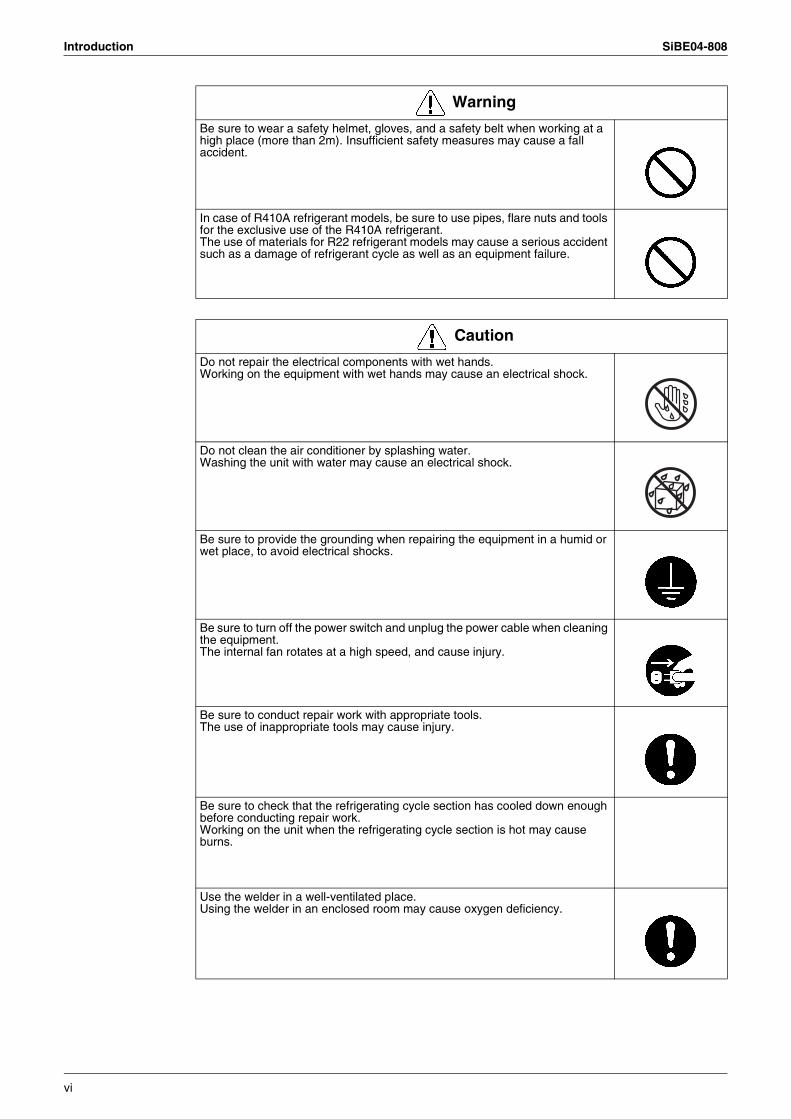
Be sure to wear a safety helmet, gloves, and a safety belt when working at a high place (more than 2m). Insufficient safety measures may cause a fall accident.
In case of R410A refrigerant models, be sure to use pipes, flare nuts and tools for the exclusive use of the R410A refrigerant.The use of materials for R22 refrigerant models may cause a serious accident such as a damage of refrigerant cycle as well as an equipment failure.
Warning
Caution
Do not repair the electrical components with wet hands.Working on the equipment with wet hands may cause an electrical shock.
Do not clean the air conditioner by splashing water.Washing the unit with water may cause an electrical shock.
Be sure to provide the grounding when repairing the equipment in a humid or wet place, to avoid electrical shocks.
Be sure to turn off the power switch and unplug the power cable when cleaning the equipment.The internal fan rotates at a high speed, and cause injury.
Be sure to conduct repair work with appropriate tools.The use of inappropriate tools may cause injury.
Be sure to check that the refrigerating cycle section has cooled down enough before conducting repair work.Working on the unit when the refrigerating cycle section is hot may cause burns.
Use the welder in a well-ventilated place.Using the welder in an enclosed room may cause oxygen deficiency.
vi
SiBE04-808 Introduction
1.1.2 Cautions Regarding Safety of Users
Warning
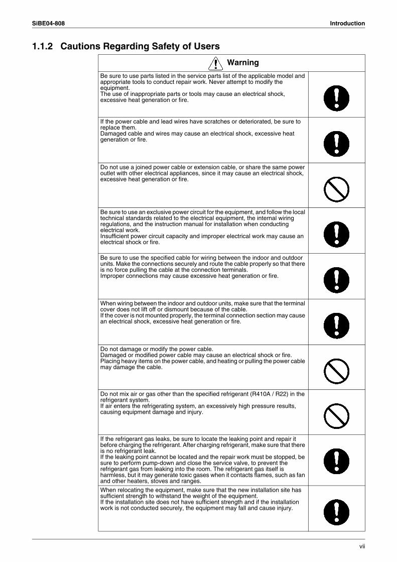
Be sure to use parts listed in the service parts list of the applicable model and appropriate tools to conduct repair work. Never attempt to modify the equipment.The use of inappropriate parts or tools may cause an electrical shock, excessive heat generation or fire.
If the power cable and lead wires have scratches or deteriorated, be sure to replace them.Damaged cable and wires may cause an electrical shock, excessive heat generation or fire.
Do not use a joined power cable or extension cable, or share the same power outlet with other electrical appliances, since it may cause an electrical shock, excessive heat generation or fire.
Be sure to use an exclusive power circuit for the equipment, and follow the local technical standards related to the electrical equipment, the internal wiring regulations, and the instruction manual for installation when conducting electrical work.Insufficient power circuit capacity and improper electrical work may cause an electrical shock or fire.
Be sure to use the specified cable for wiring between the indoor and outdoor units. Make the connections securely and route the cable properly so that there is no force pulling the cable at the connection terminals.Improper connections may cause excessive heat generation or fire.
When wiring between the indoor and outdoor units, make sure that the terminal cover does not lift off or dismount because of the cable.If the cover is not mounted properly, the terminal connection section may cause an electrical shock, excessive heat generation or fire.
Do not damage or modify the power cable.Damaged or modified power cable may cause an electrical shock or fire.Placing heavy items on the power cable, and heating or pulling the power cable may damage the cable.
Do not mix air or gas other than the specified refrigerant (R410A / R22) in the refrigerant system.If air enters the refrigerating system, an excessively high pressure results, causing equipment damage and injury.
If the refrigerant gas leaks, be sure to locate the leaking point and repair it before charging the refrigerant. After charging refrigerant, make sure that there is no refrigerant leak.If the leaking point cannot be located and the repair work must be stopped, be sure to perform pump-down and close the service valve, to prevent the refrigerant gas from leaking into the room. The refrigerant gas itself is harmless, but it may generate toxic gases when it contacts flames, such as fan and other heaters, stoves and ranges.
When relocating the equipment, make sure that the new installation site has sufficient strength to withstand the weight of the equipment.If the installation site does not have sufficient strength and if the installation work is not conducted securely, the equipment may fall and cause injury.
vii
Introduction SiBE04-808
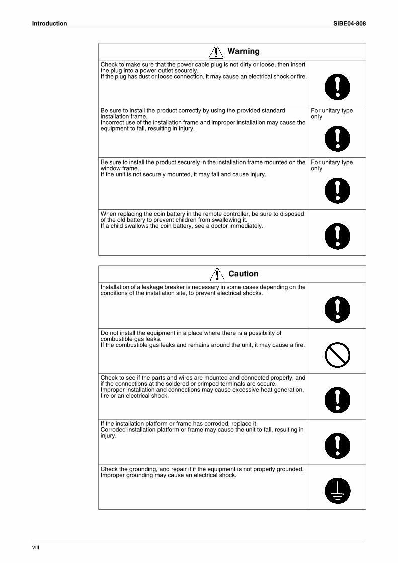
Check to make sure that the power cable plug is not dirty or loose, then insert the plug into a power outlet securely.If the plug has dust or loose connection, it may cause an electrical shock or fire.
Be sure to install the product correctly by using the provided standard installation frame.Incorrect use of the installation frame and improper installation may cause the equipment to fall, resulting in injury.
For unitary type only
Be sure to install the product securely in the installation frame mounted on the window frame.If the unit is not securely mounted, it may fall and cause injury.
For unitary type only
When replacing the coin battery in the remote controller, be sure to disposed of the old battery to prevent children from swallowing it.If a child swallows the coin battery, see a doctor immediately.
Warning
Caution
Installation of a leakage breaker is necessary in some cases depending on the conditions of the installation site, to prevent electrical shocks.
Do not install the equipment in a place where there is a possibility of combustible gas leaks.If the combustible gas leaks and remains around the unit, it may cause a fire.
Check to see if the parts and wires are mounted and connected properly, and if the connections at the soldered or crimped terminals are secure.Improper installation and connections may cause excessive heat generation, fire or an electrical shock.
If the installation platform or frame has corroded, replace it.Corroded installation platform or frame may cause the unit to fall, resulting in injury.
Check the grounding, and repair it if the equipment is not properly grounded.Improper grounding may cause an electrical shock.
viii
SiBE04-808 Introduction
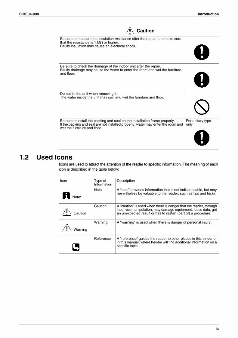
1.2 Used IconsIcons are used to attract the attention of the reader to specific information. The meaning of each icon is described in the table below:
Be sure to measure the insulation resistance after the repair, and make sure that the resistance is 1 MΩ or higher.Faulty insulation may cause an electrical shock.
Be sure to check the drainage of the indoor unit after the repair.Faulty drainage may cause the water to enter the room and wet the furniture and floor.
Do not tilt the unit when removing it.The water inside the unit may spill and wet the furniture and floor.
Be sure to install the packing and seal on the installation frame properly.If the packing and seal are not installed properly, water may enter the room and wet the furniture and floor.
For unitary type only
Caution
Icon Type of Information
Description
Note:
Note A “note” provides information that is not indispensable, but may nevertheless be valuable to the reader, such as tips and tricks.
Caution
Caution A “caution” is used when there is danger that the reader, through incorrect manipulation, may damage equipment, loose data, get an unexpected result or has to restart (part of) a procedure.
Warning
Warning A “warning” is used when there is danger of personal injury.
Reference A “reference” guides the reader to other places in this binder or in this manual, where he/she will find additional information on a specific topic.
ix
Introduction SiBE04-808
x
SiBE04-808
List of Functions 1
Part 1List of Functions
1. List of Functions ......................................................................................2
List of Functions SiBE04-808
1. List of Functions
Category Functions
FT
XS
20/2
5/35
/42G
2V1B
RK
S20
/25/
35/4
2G2V
1B
FT
XS
50G
2V1B
RK
S50
G2V
1B Category Functions
FT
XS
20/2
5/35
/42G
2V1B
RK
S20
/25/
35/4
2G2V
1B
FT
XS
50G
2V1B
RK
S50
G2V
1B
Basic Function
Inverter (with Inverter Power Control)
Health & Clean Air Purifying Filter — —
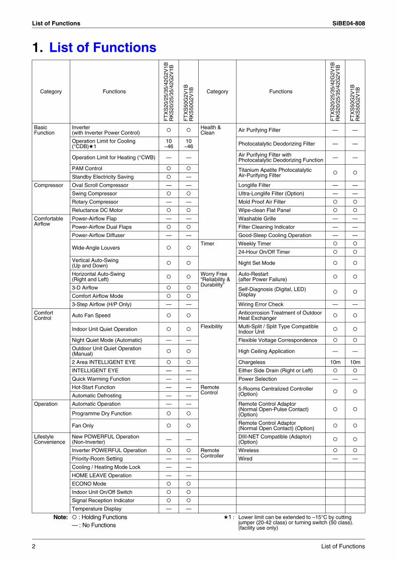
Operation Limit for Cooling (°CDB)1
10~46
10~46 Photocatalytic Deodorizing Filter — —
Operation Limit for Heating (°CWB) — — Air Purifying Filter with Photocatalytic Deodorizing Function — —
PAM Control Titanium Apatite PhotocatalyticAir-Purifying FilterStandby Electricity Saving —
Compressor Oval Scroll Compressor — — Longlife Filter — —
Swing Compressor Ultra-Longlife Filter (Option) — —
Rotary Compressor — — Mold Proof Air Filter
Reluctance DC Motor Wipe-clean Flat Panel
Comfortable Airflow
Power-Airflow Flap — — Washable Grille — —
Power-Airflow Dual Flaps Filter Cleaning Indicator — —
Power-Airflow Diffuser — — Good-Sleep Cooling Operation — —
Wide-Angle LouversTimer Weekly Timer
24-Hour On/Off Timer
Vertical Auto-Swing(Up and Down) Night Set Mode
Horizontal Auto-Swing(Right and Left)
Worry Free “Reliability & Durability”
Auto-Restart(after Power Failure)
3-D Airflow Self-Diagnosis (Digital, LED) DisplayComfort Airflow Mode
3-Step Airflow (H/P Only) — — Wiring Error Check — —
Comfort Control Auto Fan Speed Anticorrosion Treatment of Outdoor
Heat Exchanger
Indoor Unit Quiet Operation Flexibility Multi-Split / Split Type Compatible Indoor Unit
Night Quiet Mode (Automatic) — — Flexible Voltage Correspondence
Outdoor Unit Quiet Operation (Manual) High Ceiling Application — —
2 Area INTELLIGENT EYE Chargeless 10m 10m
INTELLIGENT EYE — — Either Side Drain (Right or Left)
Quick Warming Function — — Power Selection — —
Hot-Start Function — — Remote Control
5-Rooms Centralized Controller(Option)Automatic Defrosting — —
Operation Automatic Operation — — Remote Control Adaptor(Normal Open-Pulse Contact)(Option)Programme Dry Function
Fan Only Remote Control Adaptor (Normal Open Contact) (Option)
Lifestyle Convenience
New POWERFUL Operation(Non-Inverter) — — DIII-NET Compatible (Adaptor)
(Option)
Inverter POWERFUL Operation Remote Controller
Wireless
Priority-Room Setting — — Wired — —
Cooling / Heating Mode Lock — —
HOME LEAVE Operation — —
ECONO Mode
Indoor Unit On/Off Switch
Signal Reception Indicator
Temperature Display — —
Note: : Holding Functions— : No Functions
1 : Lower limit can be extended to –15°C by cutting jumper (20-42 class) or turning switch (50 class). (facility use only)
2 List of Functions
SiBE04-808 List of Functions
Category Functions
FT
XS
20/2
5/35
/42G
2V1B
RX
S20
/25/
35/4
2G2V
1B
FT
XS
50G
2V1B
RX
S50
G2V
1B Category Functions
FT
XS
20/2
5/35
/42G
2V1B
RX
S20
/25/
35/4
2G2V
1B
FT
XS
50G
2V1B
RX
S50
G2V
1B
Basic Function
Inverter (with Inverter Power Control)
Health & Clean Air Purifying Filter — —
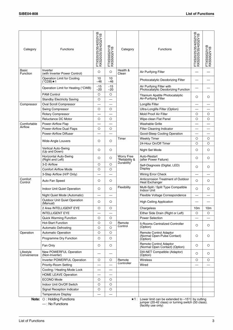
Operation Limit for Cooling (°CDB)1
10~46
10~46 Photocatalytic Deodorizing Filter — —
Operation Limit for Heating (°CWB) –15~20
–15~20
Air Purifying Filter with Photocatalytic Deodorizing Function — —
PAM Control Titanium Apatite PhotocatalyticAir-Purifying FilterStandby Electricity Saving —
Compressor Oval Scroll Compressor — — Longlife Filter — —
Swing Compressor Ultra-Longlife Filter (Option) — —
Rotary Compressor — — Mold Proof Air Filter
Reluctance DC Motor Wipe-clean Flat Panel
Comfortable Airflow
Power-Airflow Flap — — Washable Grille — —
Power-Airflow Dual Flaps Filter Cleaning Indicator — —
Power-Airflow Diffuser — — Good-Sleep Cooling Operation — —
Wide-Angle LouversTimer Weekly Timer
24-Hour On/Off Timer
Vertical Auto-Swing(Up and Down) Night Set Mode
Horizontal Auto-Swing(Right and Left)
Worry Free “Reliability & Durability”
Auto-Restart(after Power Failure)
3-D Airflow Self-Diagnosis (Digital, LED) DisplayComfort Airflow Mode
3-Step Airflow (H/P Only) — — Wiring Error Check — —
Comfort Control Auto Fan Speed Anticorrosion Treatment of Outdoor
Heat Exchanger
Indoor Unit Quiet Operation Flexibility Multi-Split / Split Type Compatible Indoor Unit
Night Quiet Mode (Automatic) — — Flexible Voltage Correspondence — —
Outdoor Unit Quiet Operation (Manual) High Ceiling Application — —
2 Area INTELLIGENT EYE Chargeless 10m 10m
INTELLIGENT EYE — — Either Side Drain (Right or Left)
Quick Warming Function Power Selection — —
Hot-Start Function Remote Control
5-Rooms Centralized Controller(Option)Automatic Defrosting
Operation Automatic Operation Remote Control Adaptor(Normal Open-Pulse Contact)(Option)Programme Dry Function
Fan Only Remote Control Adaptor (Normal Open Contact) (Option)
Lifestyle Convenience
New POWERFUL Operation(Non-Inverter) — — DIII-NET Compatible (Adaptor)
(Option)
Inverter POWERFUL Operation Remote Controller
Wireless
Priority-Room Setting — — Wired — —
Cooling / Heating Mode Lock — —
HOME LEAVE Operation — —
ECONO Mode
Indoor Unit On/Off Switch
Signal Reception Indicator
Temperature Display — —
Note: : Holding Functions— : No Functions
1 : Lower limit can be extended to –15°C by cutting jumper (20-42 class) or turning switch (50 class). (facility use only)
List of Functions 3
List of Functions SiBE04-808
Category Functions
AT
XS
20/2
5/35
/42G
2V1B
AR
XS
20/2
5/35
/42G
2V1B
AT
XS
50G
2V1B
AR
XS
50G
2V1B Category Functions
AT
XS
20/2
5/35
/42G
2V1B
AR
XS
20/2
5/35
/42G
2V1B
AT
XS
50G
2V1B
AR
XS
50G
2V1B
Basic Function
Inverter (with Inverter Power Control)
Health & Clean Air Purifying Filter — —
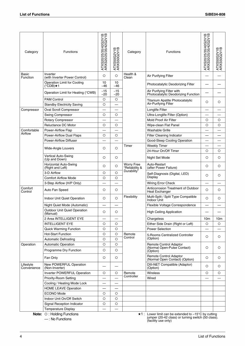
Operation Limit for Cooling (°CDB)1
10~46
10~46 Photocatalytic Deodorizing Filter — —
Operation Limit for Heating (°CWB) –15~20
–15~20
Air Purifying Filter with Photocatalytic Deodorizing Function — —
PAM Control Titanium Apatite PhotocatalyticAir-Purifying FilterStandby Electricity Saving —
Compressor Oval Scroll Compressor — — Longlife Filter — —
Swing Compressor Ultra-Longlife Filter (Option) — —
Rotary Compressor — — Mold Proof Air Filter
Reluctance DC Motor Wipe-clean Flat Panel
Comfortable Airflow
Power-Airflow Flap — — Washable Grille — —
Power-Airflow Dual Flaps Filter Cleaning Indicator — —
Power-Airflow Diffuser — — Good-Sleep Cooling Operation — —
Wide-Angle LouversTimer Weekly Timer — —
24-Hour On/Off Timer
Vertical Auto-Swing(Up and Down) Night Set Mode
Horizontal Auto-Swing(Right and Left)
Worry Free “Reliability & Durability”
Auto-Restart(after Power Failure)
3-D Airflow Self-Diagnosis (Digital, LED) DisplayComfort Airflow Mode
3-Step Airflow (H/P Only) — — Wiring Error Check — —
Comfort Control Auto Fan Speed Anticorrosion Treatment of Outdoor
Heat Exchanger
Indoor Unit Quiet Operation Flexibility Multi-Split / Split Type Compatible Indoor Unit
Night Quiet Mode (Automatic) — — Flexible Voltage Correspondence — —
Outdoor Unit Quiet Operation (Manual) High Ceiling Application — —
2 Area INTELLIGENT EYE — — Chargeless 10m 10m
INTELLIGENT EYE Either Side Drain (Right or Left)
Quick Warming Function Power Selection — —
Hot-Start Function Remote Control
5-Rooms Centralized Controller(Option)Automatic Defrosting
Operation Automatic Operation Remote Control Adaptor(Normal Open-Pulse Contact)(Option)Programme Dry Function
Fan Only Remote Control Adaptor (Normal Open Contact) (Option)
Lifestyle Convenience
New POWERFUL Operation(Non-Inverter) — — DIII-NET Compatible (Adaptor)
(Option)
Inverter POWERFUL Operation Remote Controller
Wireless
Priority-Room Setting — — Wired — —
Cooling / Heating Mode Lock — —
HOME LEAVE Operation — —
ECONO Mode
Indoor Unit On/Off Switch
Signal Reception Indicator
Temperature Display — —
Note: : Holding Functions— : No Functions
1 : Lower limit can be extended to –15°C by cutting jumper (20-42 class) or turning switch (50 class). (facility use only)
4 List of Functions
SiBE04-808
Specifications 5
Part 2Specifications
1. Specifications ..........................................................................................61.1 Cooling Only.............................................................................................61.2 Heat Pump ...............................................................................................8
Specifications SiBE04-808
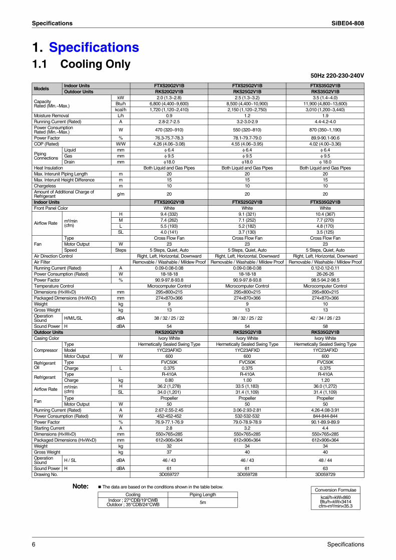
1. Specifications1.1 Cooling Only
50Hz 220-230-240V
Note: The data are based on the conditions shown in the table below.
ModelsIndoor Units FTXS20G2V1B FTXS25G2V1B FTXS35G2V1BOutdoor Units RKS20G2V1B RKS25G2V1B RKS35G2V1B
Capacity Rated (Min.~Max.)
kW 2.0 (1.3~2.8) 2.5 (1.3~3.2) 3.5 (1.4~4.0)Btu/h 6,800 (4,400~9,600) 8,500 (4,400~10,900) 11,900 (4,800~13,600)kcal/h 1,720 (1,120~2,410) 2,150 (1,120~2,750) 3,010 (1,200~3,440)
Moisture Removal L/h 0.9 1.2 1.9Running Current (Rated) A 2.8-2.7-2.5 3.2-3.0-2.9 4.4-4.2-4.0Power Consumption Rated (Min.~Max.) W 470 (320~910) 550 (320~810) 870 (350~1,190)
Power Factor % 76.3-75.7-78.3 78.1-79.7-79.0 89.9-90.1-90.6COP (Rated) W/W 4.26 (4.06~3.08) 4.55 (4.06~3.95) 4.02 (4.00~3.36)
Piping Connections
Liquid mm φ 6.4 φ 6.4 φ 6.4Gas mm φ 9.5 φ 9.5 φ 9.5Drain mm φ18.0 φ18.0 φ 18.0
Heat Insulation Both Liquid and Gas Pipes Both Liquid and Gas Pipes Both Liquid and Gas PipesMax. lnterunit Piping Length m 20 20 20Max. lnterunit Height Difference m 15 15 15Chargeless m 10 10 10Amount of Additional Charge of Refrigerant g/m 20 20 20
Indoor Units FTXS20G2V1B FTXS25G2V1B FTXS35G2V1BFront Panel Color White White White
Airflow Rate m³/min (cfm)
H 9.4 (332) 9.1 (321) 10.4 (367)M 7.4 (262) 7.1 (252) 7.7 (270)L 5.5 (193) 5.2 (182) 4.8 (170)
SL 4.0 (141) 3.7 (130) 3.5 (125)
FanType Cross Flow Fan Cross Flow Fan Cross Flow FanMotor Output W 23 23 23Speed Steps 5 Steps, Quiet, Auto 5 Steps, Quiet, Auto 5 Steps, Quiet, Auto
Air Direction Control Right, Left, Horizontal, Downward Right, Left, Horizontal, Downward Right, Left, Horizontal, DownwardAir Filter Removable / Washable / Mildew Proof Removable / Washable / Mildew Proof Removable / Washable / Mildew ProofRunning Current (Rated) A 0.09-0.08-0.08 0.09-0.08-0.08 0.12-0.12-0.11Power Consumption (Rated) W 18-18-18 18-18-18 26-26-26Power Factor % 90.9-97.8-93.8 90.9-97.8-93.8 98.5-94.2-98.5Temperature Control Microcomputer Control Microcomputer Control Microcomputer ControlDimensions (H×W×D) mm 295×800×215 295×800×215 295×800×215Packaged Dimensions (H×W×D) mm 274×870×366 274×870×366 274×870×366Weight kg 9 9 10Gross Weight kg 13 13 13Operation Sound H/M/L/SL dBA 38 / 32 / 25 / 22 38 / 32 / 25 / 22 42 / 34 / 26 / 23
Sound Power H dBA 54 54 58Outdoor Units RKS20G2V1B RKS25G2V1B RKS35G2V1BCasing Color Ivory White Ivory White Ivory White
CompressorType Hermetically Sealed Swing Type Hermetically Sealed Swing Type Hermetically Sealed Swing TypeModel 1YC23AFXD 1YC23AFXD 1YC23AFXDMotor Output W 600 600 600
Refrigerant Oil
Type FVC50K FVC50K FVC50KCharge L 0.375 0.375 0.375
RefrigerantType R-410A R-410A R-410ACharge kg 0.80 1.00 1.20
Airflow Rate m³/min (cfm)
H 36.2 (1,278) 33.5 (1,183) 36.0 (1,272)SL 34.0 (1,201) 31.4 (1,109) 31.4 (1,109)
FanType Propeller Propeller PropellerMotor Output W 50 50 50
Running Current (Rated) A 2.67-2.55-2.45 3.06-2.93-2.81 4.26-4.08-3.91Power Consumption (Rated) W 452-452-452 532-532-532 844-844-844Power Factor % 76.9-77.1-76.9 79.0-78.9-78.9 90.1-89.9-89.9Starting Current A 2.8 3.2 4.4Dimensions (H×W×D) mm 550×765×285 550×765×285 550×765×285Packaged Dimensions (H×W×D) mm 612×906×364 612×906×364 612×906×364Weight kg 32 34 34Gross Weight kg 37 40 40Operation Sound H / SL dBA 46 / 43 46 / 43 48 / 44
Sound Power H dBA 61 61 63Drawing No. 3D059727 3D059728 3D059729
Conversion Formulae
kcal/h=kW×860Btu/h=kW×3414
cfm=m³/min×35.3
Cooling Piping LengthIndoor ; 27°CDB/19°CWB
Outdoor ; 35°CDB/24°CWB 5m
6 Specifications
SiBE04-808 Specifications
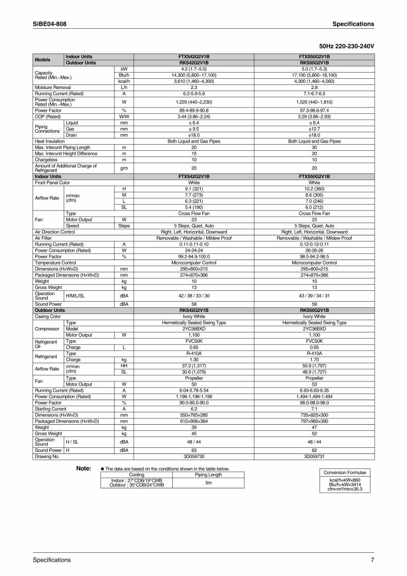
50Hz 220-230-240V
Note: The data are based on the conditions shown in the table below.
ModelsIndoor Units FTXS42G2V1B FTXS50G2V1BOutdoor Units RKS42G2V1B RKS50G2V1B
Capacity Rated (Min.~Max.)
kW 4.2 (1.7~5.0) 5.0 (1.7~5.3)Btu/h 14,300 (5,800~17,100) 17,100 (5,800~18,100)kcal/h 3,610 (1,460~4,300) 4,300 (1,460~4,560)
Moisture Removal L/h 2.3 2.8Running Current (Rated) A 6.2-5.9-5.6 7.1-6.7-6.5Power Consumption Rated (Min.~Max.) W 1,220 (440~2,230) 1,520 (440~1,810)
Power Factor % 89.4-89.9-90.8 97.3-98.6-97.4COP (Rated) W/W 3.44 (3.86~2.24) 3.29 (3.86~2.93)
Piping Connections
Liquid mm φ 6.4 φ 6.4Gas mm φ 9.5 φ12.7Drain mm φ18.0 φ18.0
Heat Insulation Both Liquid and Gas Pipes Both Liquid and Gas PipesMax. Interunit Piping Length m 20 30Max. Interunit Height Difference m 15 20Chargeless m 10 10Amount of Additional Charge of Refrigerant g/m 20 20
Indoor Units FTXS42G2V1B FTXS50G2V1BFront Panel Color White White
Airflow Rate m³/min (cfm)
H 9.1 (321) 10.2 (360)M 7.7 (273) 8.6 (305)L 6.3 (221) 7.0 (246)
SL 5.4 (190) 6.0 (212)
FanType Cross Flow Fan Cross Flow FanMotor Output W 23 23Speed Steps 5 Steps, Quiet, Auto 5 Steps, Quiet, Auto
Air Direction Control Right, Left, Horizontal, Downward Right, Left, Horizontal, DownwardAir Filter Removable / Washable / Mildew Proof Removable / Washable / Mildew ProofRunning Current (Rated) A 0.11-0.11-0.10 0.12-0.12-0.11Power Consumption (Rated) W 24-24-24 26-26-26Power Factor % 99.2-94.9-100.0 98.5-94.2-98.5Temperature Control Microcomputer Control Microcomputer ControlDimensions (H×W×D) mm 295×800×215 295×800×215Packaged Dimensions (H×W×D) mm 274×870×366 274×870×366Weight kg 10 10Gross Weight kg 13 13Operation Sound H/M/L/SL dBA 42 / 38 / 33 / 30 43 / 39 / 34 / 31
Sound Power dBA 58 59Outdoor Units RKS42G2V1B RKS50G2V1BCasing Color Ivory White Ivory White
CompressorType Hermetically Sealed Swing Type Hermetically Sealed Swing TypeModel 2YC36BXD 2YC36BXDMotor Output W 1,100 1,100
Refrigerant Oil
Type FVC50K FVC50KCharge L 0.65 0.65
RefrigerantType R-410A R-410ACharge kg 1.30 1.70
Airflow Rate m³/min (cfm)
HH 37.3 (1,317) 50.9 (1,797)SL 30.6 (1,079) 48.9 (1,727)
FanType Propeller PropellerMotor Output W 50 53
Running Current (Rated) A 6.04-5.78-5.54 6.93-6.63-6.35Power Consumption (Rated) W 1,196-1,196-1,196 1,494-1,494-1,494Power Factor % 90.0-90.0-90.0 98.0-98.0-98.0Starting Current A 6.2 7.1Dimensions (H×W×D) mm 550×765×285 735×825×300Packaged Dimensions (H×W×D) mm 612×906×364 797×960×390Weight kg 39 47Gross Weight kg 45 52Operation Sound H / SL dBA 48 / 44 48 / 44
Sound Power H dBA 63 62Drawing No. 3D059730 3D059731
Conversion Formulae
kcal/h=kW×860Btu/h=kW×3414
cfm=m³/min×35.3
Cooling Piping LengthIndoor ; 27°CDB/19°CWB
Outdoor ; 35°CDB/24°CWB 5m
Specifications 7
Specifications SiBE04-808
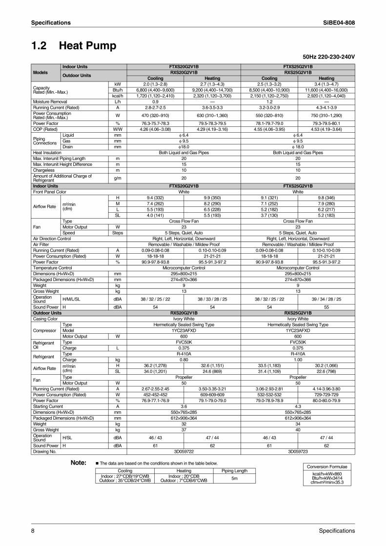
1.2 Heat Pump50Hz 220-230-240V
Note: The data are based on the conditions shown in the table below.
ModelsIndoor Units FTXS20G2V1B FTXS25G2V1B
Outdoor UnitsRXS20G2V1B RXS25G2V1B
Cooling Heating Cooling Heating
Capacity Rated (Min.~Max.)
kW 2.0 (1.3~2.8) 2.7 (1.3~4.3) 2.5 (1.3~3.2) 3.4 (1.3~4.7)Btu/h 6,800 (4,400~9,600) 9,200 (4,400~14,700) 8,500 (4,400~10,900) 11,600 (4,400~16,000)kcal/h 1,720 (1,120~2,410) 2,320 (1,120~3,700) 2,150 (1,120~2,750) 2,920 (1,120~4,040)
Moisture Removal L/h 0.9 — 1.2 —Running Current (Rated) A 2.8-2.7-2.5 3.6-3.5-3.3 3.2-3.0-2.9 4.3-4.1-3.9Power Consumption Rated (Min.~Max.) W 470 (320~910) 630 (310~1,360) 550 (320~810) 750 (310~1,290)
Power Factor % 76.3-75.7-78.3 79.5-78.3-79.5 78.1-79.7-79.0 79.3-79.5-80.1COP (Rated) W/W 4.26 (4.06~3.08) 4.29 (4.19~3.16) 4.55 (4.06~3.95) 4.53 (4.19~3.64)
Piping Connections
Liquid mm φ 6.4 φ 6.4Gas mm φ 9.5 φ 9.5Drain mm φ18.0 φ 18.0
Heat Insulation Both Liquid and Gas Pipes Both Liquid and Gas PipesMax. lnterunit Piping Length m 20 20Max. lnterunit Height Difference m 15 15Chargeless m 10 10Amount of Additional Charge of Refrigerant g/m 20 20
Indoor Units FTXS20G2V1B FTXS25G2V1BFront Panel Color White White
Airflow Rate m³/min (cfm)
H 9.4 (332) 9.9 (350) 9.1 (321) 9.8 (346)M 7.4 (262) 8.2 (290) 7.1 (252) 7.9 (280)L 5.5 (193) 6.5 (228) 5.2 (182) 6.2 (217)
SL 4.0 (141) 5.5 (193) 3.7 (130) 5.2 (183)
FanType Cross Flow Fan Cross Flow FanMotor Output W 23 23Speed Steps 5 Steps, Quiet, Auto 5 Steps, Quiet, Auto
Air Direction Control Right, Left, Horizontal, Downward Right, Left, Horizontal, DownwardAir Filter Removable / Washable / Mildew Proof Removable / Washable / Mildew ProofRunning Current (Rated) A 0.09-0.08-0.08 0.10-0.10-0.09 0.09-0.08-0.08 0.10-0.10-0.09Power Consumption (Rated) W 18-18-18 21-21-21 18-18-18 21-21-21Power Factor % 90.9-97.8-93.8 95.5-91.3-97.2 90.9-97.8-93.8 95.5-91.3-97.2Temperature Control Microcomputer Control Microcomputer ControlDimensions (H×W×D) mm 295×800×215 295×800×215Packaged Dimensions (H×W×D) mm 274×870×366 274×870×366Weight kg 9 9Gross Weight kg 13 13Operation Sound H/M/L/SL dBA 38 / 32 / 25 / 22 38 / 33 / 28 / 25 38 / 32 / 25 / 22 39 / 34 / 28 / 25
Sound Power H dBA 54 54 54 55Outdoor Units RXS20G2V1B RXS25G2V1BCasing Color Ivory White Ivory White
CompressorType Hermetically Sealed Swing Type Hermetically Sealed Swing TypeModel 1YC23AFXD 1YC23AFXDMotor Output W 600 600
Refrigerant Oil
Type FVC50K FVC50KCharge L 0.375 0.375
RefrigerantType R-410A R-410ACharge kg 0.80 1.00
Airflow Rate m³/min(cfm)
H 36.2 (1,278) 32.6 (1,151) 33.5 (1,183) 30.2 (1,066)SL 34.0 (1,201) 24.6 (869) 31.4 (1,109) 22.6 (798)
FanType Propeller PropellerMotor Output W 50 50
Running Current (Rated) A 2.67-2.55-2.45 3.50-3.35-3.21 3.06-2.93-2.81 4.14-3.96-3.80Power Consumption (Rated) W 452-452-452 609-609-609 532-532-532 729-729-729Power Factor % 76.9-77.1-76.9 79.1-79.0-79.0 79.0-78.9-78.9 80.0-80.0-79.9Starting Current A 3.6 4.3Dimensions (H×W×D) mm 550×765×285 550×765×285Packaged Dimensions (H×W×D) mm 612×906×364 612×906×364Weight kg 32 34Gross Weight kg 37 40Operation Sound H/SL dBA 46 / 43 47 / 44 46 / 43 47 / 44
Sound Power H dBA 61 62 61 62Drawing No. 3D059722 3D059723
Conversion Formulae
kcal/h=kW×860Btu/h=kW×3414
cfm=m³/min×35.3
Cooling Heating Piping LengthIndoor ; 27°CDB/19°CWB
Outdoor ; 35°CDB/24°CWBIndoor ; 20°CDB
Outdoor ; 7°CDB/6°CWB 5m
8 Specifications

SiBE04-808 Specifications
50Hz 220-230-240V
Note: The data are based on the conditions shown in the table below.
ModelsIndoor Units FTXS35G2V1B FTXS42G2V1B
Outdoor UnitsRXS35G2V1B RXS42G2V1B
Cooling Heating Cooling Heating
Capacity Rated (Min.~Max.)
kW 3.5 (1.4~4.0) 4.0 (1.4~5.2) 4.2 (1.7~5.0) 5.4 (1.7~6.0)Btu/h 11,900 (4,800~13,600) 13,600 (4,800~17,700) 14,300 (5,800~17,100) 18,400 (5,800~20,500)kcal/h 3,010 (1,200~3,440) 3,440 (1,200~4,470) 3,610 (1,460~4,300) 4,640 (1,460~5,160)
Moisture Removal L/h 1.9 — 2.3 —Running Current (Rated) A 4.4-4.2-4.0 4.8-4.6-4.4 6.2-5.9-5.6 7.4-7.1-6.8Power Consumption Rated (Min.~Max.) W 870 (350~1,190) 960 (340~1,460) 1,220 (440~2,230) 1,470 (400~1,980)
Power Factor % 89.9-90.1-90.6 90.9-90.7-90.9 89.4-89.9-90.8 90.3-90.0-90.1COP (Rated) W/W 4.02 (4.00~3.96) 4.17 (4.12~3.56) 3.44 (3.86~2.24) 3.67 (4.25~3.03)
Piping Connections
Liquid mm φ 6.4 φ 6.4Gas mm φ 9.5 φ 9.5Drain mm φ 18.0 φ18.0
Heat Insulation Both Liquid and Gas Pipes Both Liquid and Gas PipesMax. lnterunit Piping Length m 20 20Max. lnterunit Height Difference m 15 15Chargeless m 10 10Amount of Additional Charge of Refrigerant g/m 20 20
Indoor Units FTXS35G2V1B FTXS42G2V1BFront Panel Color White White
Airflow Rate m³/min (cfm)
H 10.4 (367) 10.6 (374) 9.1 (321) 11.2 (395)M 7.7 (270) 8.5 (302) 7.7 (273) 9.4 (333)L 4.8 (170) 6.4 (226) 6.3 (221) 7.7 (271)
SL 3.5 (125) 5.4 (191) 5.4 (190) 6.8 (240)
FanType Cross Flow Fan Cross Flow FanMotor Output W 23 23Speed Steps 5 Steps, Quiet, Auto 5 Steps, Quiet, Auto
Air Direction Control Right, Left, Horizontal, Downward Right, Left, Horizontal, DownwardAir Filter Removable / Washable / Mildew Proof Removable / Washable / Mildew ProofRunning Current (Rated) A 0.12-0.12-0.11 0.13-0.13-0.12 0.11-0.11-0.10 0.14-0.14-0.13Power Consumption (Rated) W 26-26-26 28-28-28 24-24-24 30-30-30Power Factor % 98.5-94.2-98.5 97.9-93.6-97.2 99.2-94.9-100.0 97.4-93.2-96.2Temperature Control Microcomputer Control Microcomputer ControlDimensions (H×W×D) mm 295×800×215 295×800×215Packaged Dimensions (H×W×D) mm 274×870×366 274×870×366Weight kg 10 10Gross Weight kg 13 13Operation Sound H/M/L/SL dBA 42 / 34 / 26 / 23 42 / 36 / 29 / 26 42 / 38 / 33 / 30 42 / 38 / 33 / 30
Sound Power H dBA 58 58 58 58Outdoor Units RXS35G2V1B RXS42G2V1BCasing Color Ivory White Ivory White
CompressorType Hermetically Sealed Swing Type Hermetically Sealed Swing TypeModel 1YC23AFXD 2YC36BXDMotor Output W 600 1,100
Refrigerant Oil
Type FVC50K FVC50KCharge L 0.375 0.65
RefrigerantType R-410A R-410ACharge kg 1.20 1.30
Airflow Rate m³/min(cfm)
H 36.0 (1,272) 30.2 (1,066) 37.3 (1,317) 31.3 (1,107)SL 31.4 (1,109) 22.6 (798) 30.6 (1,079) 27.2 (959)
FanType Propeller PropellerMotor Output W 50 50
Running Current (Rated) A 4.26-4.08-3.91 4.71-4.50-4.31 6.04-5.78-5.54 7.27-6.96-6.67Power Consumption (Rated) W 844-844-844 932-932-932 1,196-1,196-1,196 1,440-1,440-1,440Power Factor % 90.1-89.9-89.9 89.9-90.0-90.1 90.0-90.0-90.0 90.0-90.0-90.0Starting Current A 4.8 7.4Dimensions (H×W×D) mm 550×765×285 550×765×285Packaged Dimensions (H×W×D) mm 612×906×364 612×906×364Weight kg 34 39Gross Weight kg 40 45Operation Sound H/SL dBA 48 / 44 48 / 45 48 / 44 48 / 45
Sound Power dBA 63 63 63 63Drawing No. 3D059724 3D059725
Conversion Formulae
kcal/h=kW×860Btu/h=kW×3414
cfm=m³/min×35.3
Cooling Heating Piping LengthIndoor ; 27°CDB/19°CWB
Outdoor ; 35°CDB/24°CWBIndoor ; 20°CDB
Outdoor ; 7°CDB/6°CWB 5m
Specifications 9
Specifications SiBE04-808
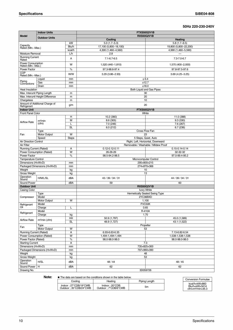
50Hz 220-230-240V
Note: The data are based on the conditions shown in the table below.
ModelIndoor Units FTXS50G2V1B
Outdoor UnitsRXS50G2V1B
Cooling Heating
Capacity Rated (Min.~Max.)
kW 5.0 (1.7~5.3) 5.8 (1.7~6.5)Btu/h 17,100 (5,800~18,100) 19,800 (5,800~22,200)kcal/h 4,300 (1,460~4,560) 4,990 (1,460~5,590)
Moisture Removal L/h 2.8 —Running CurrentRated A 7.1-6.7-6.5 7.3-7.0-6.7
Power Consumption Rated (Min.~Max.) W 1,520 (440~1,810) 1,570 (400~2,000)
Power Factor % 97.3-98.6-97.4 97.8-97.5-97.6COPRated (Min.~Max.) W/W 3.29 (3.86~2.93) 3.69 (4.25~3.25)
Piping Connections
Liquid mm φ 6.4Gas mm φ12.7Drain mm φ18.0
Heat Insulation Both Liquid and Gas PipesMax. Interunit Piping Length m 30Max. Interunit Height Difference m 20Chargeless m 10Amount of Additional Charge of Refrigerant g/m 20
Indoor Unit FTXS50G2V1BFront Panel Color White
Airflow Rate m³/min (cfm)
H 10.2 (360) 11.0 (388)M 8.6 (305) 9.3 (330)L 7.0 (246) 7.6 (267)
SL 6.0 (212) 6.7 (236)
FanType Cross Flow FanMotor Output W 23Speed Steps 5 Steps, Quiet, Auto
Air Direction Control Right, Left, Horizontal, DownwardAir Filter Removable / Washable / Mildew ProofRunning Current (Rated) A 0.12-0.12-0.11 0.15-0.14-0.14Power Consumption (Rated) W 26-26-26 32-32-32Power Factor % 98.5-94.2-98.5 97.0-99.4-95.2Temperature Control Microcomputer ControlDimensions (H×W×D) mm 295×800×215Packaged Dimensions (H×W×D) mm 274×870×366Weight kg 10Gross Weight kg 13Operation Sound H/M/L/SL dBA 43 / 39 / 34 / 31 44 / 39 / 34 / 31
Sound Power dBA 59 60Outdoor Unit RXS50G2V1BCasing Color Ivory White
CompressorType Hermetically Sealed Swing TypeModel 2YC36BXDMotor Output W 1,100
Refrigerant Oil
Model FVC50KCharge L 0.65
RefrigerantModel R-410ACharge kg 1.70
Airflow Rate m³/min (cfm)HH 50.9 (1,797) 45.0 (1,589)SL 48.9 (1,727) 43.1 (1,522)
FanType PropellerMotor Output W 53
Running Current (Rated) A 6.93-6.63-6.35 7.13-6.82-6.54Power Consumption (Rated) W 1,494-1,494-1,494 1,538-1,538-1,538Power Factor (Rated) % 98.0-98.0-98.0 98.0-98.0-98.0Starting Current A 7.3Dimensions (H×W×D) mm 735×825×300Packaged Dimensions (H×W×D) mm 797×960×390Weight kg 48Gross Weight kg 53Operation Sound H/SL dBA 48 / 44 48 / 45
Sound Power H dBA 62 62Drawing No. 3D059726
Conversion Formulae
kcal/h=kW×860Btu/h=kW×3414
cfm=m³/min×35.3
Cooling Heating Piping Length
Indoor ; 27°CDB/19°CWB Outdoor ; 35°CDB/24°CWB
Indoor ; 20°CDBOutdoor ; 7°CDB/6°CWB 5m
10 Specifications
SiBE04-808 Specifications
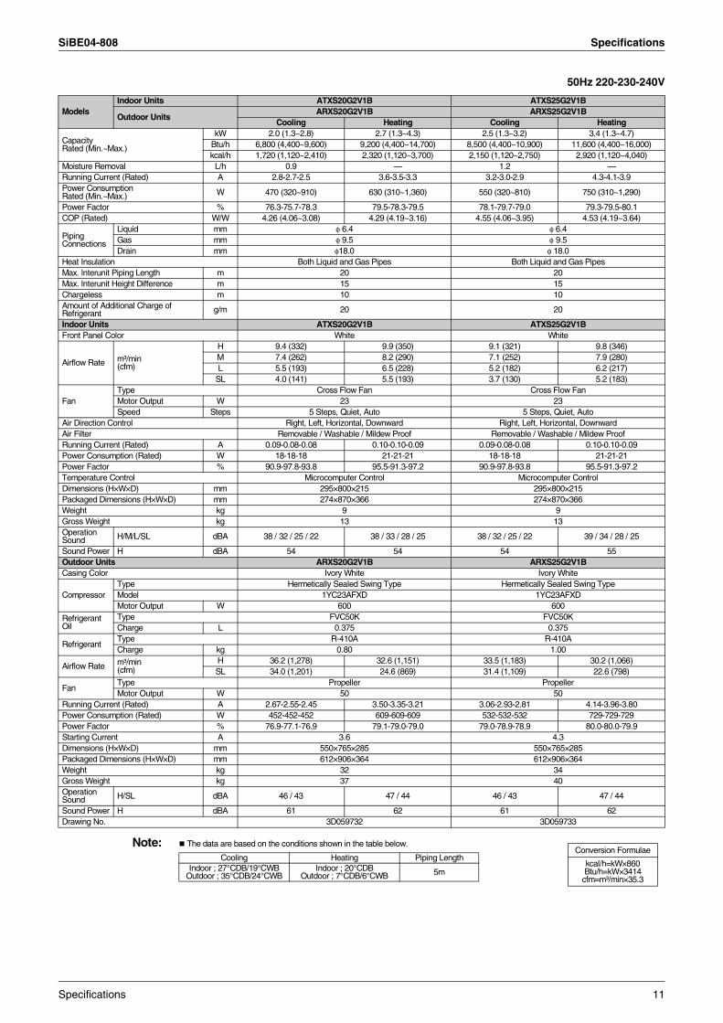
50Hz 220-230-240V
Note: The data are based on the conditions shown in the table below.
ModelsIndoor Units ATXS20G2V1B ATXS25G2V1B
Outdoor UnitsARXS20G2V1B ARXS25G2V1B
Cooling Heating Cooling Heating
Capacity Rated (Min.~Max.)
kW 2.0 (1.3~2.8) 2.7 (1.3~4.3) 2.5 (1.3~3.2) 3.4 (1.3~4.7)Btu/h 6,800 (4,400~9,600) 9,200 (4,400~14,700) 8,500 (4,400~10,900) 11,600 (4,400~16,000)kcal/h 1,720 (1,120~2,410) 2,320 (1,120~3,700) 2,150 (1,120~2,750) 2,920 (1,120~4,040)
Moisture Removal L/h 0.9 — 1.2 —Running Current (Rated) A 2.8-2.7-2.5 3.6-3.5-3.3 3.2-3.0-2.9 4.3-4.1-3.9Power Consumption Rated (Min.~Max.) W 470 (320~910) 630 (310~1,360) 550 (320~810) 750 (310~1,290)
Power Factor % 76.3-75.7-78.3 79.5-78.3-79.5 78.1-79.7-79.0 79.3-79.5-80.1COP (Rated) W/W 4.26 (4.06~3.08) 4.29 (4.19~3.16) 4.55 (4.06~3.95) 4.53 (4.19~3.64)
Piping Connections
Liquid mm φ 6.4 φ 6.4Gas mm φ 9.5 φ 9.5Drain mm φ18.0 φ 18.0
Heat Insulation Both Liquid and Gas Pipes Both Liquid and Gas PipesMax. lnterunit Piping Length m 20 20Max. lnterunit Height Difference m 15 15Chargeless m 10 10Amount of Additional Charge of Refrigerant g/m 20 20
Indoor Units ATXS20G2V1B ATXS25G2V1BFront Panel Color White White
Airflow Rate m³/min (cfm)
H 9.4 (332) 9.9 (350) 9.1 (321) 9.8 (346)M 7.4 (262) 8.2 (290) 7.1 (252) 7.9 (280)L 5.5 (193) 6.5 (228) 5.2 (182) 6.2 (217)
SL 4.0 (141) 5.5 (193) 3.7 (130) 5.2 (183)
FanType Cross Flow Fan Cross Flow FanMotor Output W 23 23Speed Steps 5 Steps, Quiet, Auto 5 Steps, Quiet, Auto
Air Direction Control Right, Left, Horizontal, Downward Right, Left, Horizontal, DownwardAir Filter Removable / Washable / Mildew Proof Removable / Washable / Mildew ProofRunning Current (Rated) A 0.09-0.08-0.08 0.10-0.10-0.09 0.09-0.08-0.08 0.10-0.10-0.09Power Consumption (Rated) W 18-18-18 21-21-21 18-18-18 21-21-21Power Factor % 90.9-97.8-93.8 95.5-91.3-97.2 90.9-97.8-93.8 95.5-91.3-97.2Temperature Control Microcomputer Control Microcomputer ControlDimensions (H×W×D) mm 295×800×215 295×800×215Packaged Dimensions (H×W×D) mm 274×870×366 274×870×366Weight kg 9 9Gross Weight kg 13 13Operation Sound H/M/L/SL dBA 38 / 32 / 25 / 22 38 / 33 / 28 / 25 38 / 32 / 25 / 22 39 / 34 / 28 / 25
Sound Power H dBA 54 54 54 55Outdoor Units ARXS20G2V1B ARXS25G2V1BCasing Color Ivory White Ivory White
CompressorType Hermetically Sealed Swing Type Hermetically Sealed Swing TypeModel 1YC23AFXD 1YC23AFXDMotor Output W 600 600
Refrigerant Oil
Type FVC50K FVC50KCharge L 0.375 0.375
RefrigerantType R-410A R-410ACharge kg 0.80 1.00
Airflow Rate m³/min(cfm)
H 36.2 (1,278) 32.6 (1,151) 33.5 (1,183) 30.2 (1,066)SL 34.0 (1,201) 24.6 (869) 31.4 (1,109) 22.6 (798)
FanType Propeller PropellerMotor Output W 50 50
Running Current (Rated) A 2.67-2.55-2.45 3.50-3.35-3.21 3.06-2.93-2.81 4.14-3.96-3.80Power Consumption (Rated) W 452-452-452 609-609-609 532-532-532 729-729-729Power Factor % 76.9-77.1-76.9 79.1-79.0-79.0 79.0-78.9-78.9 80.0-80.0-79.9Starting Current A 3.6 4.3Dimensions (H×W×D) mm 550×765×285 550×765×285Packaged Dimensions (H×W×D) mm 612×906×364 612×906×364Weight kg 32 34Gross Weight kg 37 40Operation Sound H/SL dBA 46 / 43 47 / 44 46 / 43 47 / 44
Sound Power H dBA 61 62 61 62Drawing No. 3D059732 3D059733
Conversion Formulae
kcal/h=kW×860Btu/h=kW×3414
cfm=m³/min×35.3
Cooling Heating Piping LengthIndoor ; 27°CDB/19°CWB
Outdoor ; 35°CDB/24°CWBIndoor ; 20°CDB
Outdoor ; 7°CDB/6°CWB 5m
Specifications 11
Specifications SiBE04-808
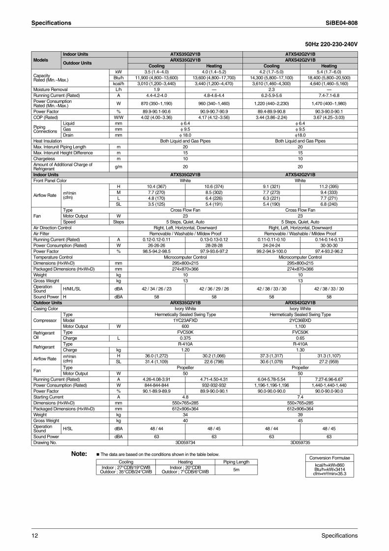
50Hz 220-230-240V
Note: The data are based on the conditions shown in the table below.
ModelsIndoor Units ATXS35G2V1B ATXS42G2V1B
Outdoor UnitsARXS35G2V1B ARXS42G2V1B
Cooling Heating Cooling Heating
Capacity Rated (Min.~Max.)
kW 3.5 (1.4~4.0) 4.0 (1.4~5.2) 4.2 (1.7~5.0) 5.4 (1.7~6.0)Btu/h 11,900 (4,800~13,600) 13,600 (4,800~17,700) 14,300 (5,800~17,100) 18,400 (5,800~20,500)kcal/h 3,010 (1,200~3,440) 3,440 (1,200~4,470) 3,610 (1,460~4,300) 4,640 (1,460~5,160)
Moisture Removal L/h 1.9 — 2.3 —Running Current (Rated) A 4.4-4.2-4.0 4.8-4.6-4.4 6.2-5.9-5.6 7.4-7.1-6.8Power Consumption Rated (Min.~Max.) W 870 (350~1,190) 960 (340~1,460) 1,220 (440~2,230) 1,470 (400~1,980)
Power Factor % 89.9-90.1-90.6 90.9-90.7-90.9 89.4-89.9-90.8 90.3-90.0-90.1COP (Rated) W/W 4.02 (4.00~3.36) 4.17 (4.12~3.56) 3.44 (3.86~2.24) 3.67 (4.25~3.03)
Piping Connections
Liquid mm φ 6.4 φ 6.4Gas mm φ 9.5 φ 9.5Drain mm φ 18.0 φ18.0
Heat Insulation Both Liquid and Gas Pipes Both Liquid and Gas PipesMax. lnterunit Piping Length m 20 20Max. lnterunit Height Difference m 15 15Chargeless m 10 10Amount of Additional Charge of Refrigerant g/m 20 20
Indoor Units ATXS35G2V1B ATXS42G2V1BFront Panel Color White White
Airflow Rate m³/min (cfm)
H 10.4 (367) 10.6 (374) 9.1 (321) 11.2 (395)M 7.7 (270) 8.5 (302) 7.7 (273) 9.4 (333)L 4.8 (170) 6.4 (226) 6.3 (221) 7.7 (271)
SL 3.5 (125) 5.4 (191) 5.4 (190) 6.8 (240)
FanType Cross Flow Fan Cross Flow FanMotor Output W 23 23Speed Steps 5 Steps, Quiet, Auto 5 Steps, Quiet, Auto
Air Direction Control Right, Left, Horizontal, Downward Right, Left, Horizontal, DownwardAir Filter Removable / Washable / Mildew Proof Removable / Washable / Mildew ProofRunning Current (Rated) A 0.12-0.12-0.11 0.13-0.13-0.12 0.11-0.11-0.10 0.14-0.14-0.13Power Consumption (Rated) W 26-26-26 28-28-28 24-24-24 30-30-30Power Factor % 98.5-94.2-98.5 97.9-93.6-97.2 99.2-94.9-100.0 97.4-93.2-96.2Temperature Control Microcomputer Control Microcomputer ControlDimensions (H×W×D) mm 295×800×215 295×800×215Packaged Dimensions (H×W×D) mm 274×870×366 274×870×366Weight kg 10 10Gross Weight kg 13 13Operation Sound H/M/L/SL dBA 42 / 34 / 26 / 23 42 / 36 / 29 / 26 42 / 38 / 33 / 30 42 / 38 / 33 / 30
Sound Power H dBA 58 58 58 58Outdoor Units ARXS35G2V1B ARXS42G2V1BCasing Color Ivory White Ivory White
CompressorType Hermetically Sealed Swing Type Hermetically Sealed Swing TypeModel 1YC23AFXD 2YC36BXDMotor Output W 600 1,100
Refrigerant Oil
Type FVC50K FVC50KCharge L 0.375 0.65
RefrigerantType R-410A R-410ACharge kg 1.20 1.30
Airflow Rate m³/min(cfm)
H 36.0 (1,272) 30.2 (1,066) 37.3 (1,317) 31.3 (1,107)SL 31.4 (1,109) 22.6 (798) 30.6 (1,079) 27.2 (959)
FanType Propeller PropellerMotor Output W 50 50
Running Current (Rated) A 4.26-4.08-3.91 4.71-4.50-4.31 6.04-5.78-5.54 7.27-6.96-6.67Power Consumption (Rated) W 844-844-844 932-932-932 1,196-1,196-1,196 1,440-1,440-1,440Power Factor % 90.1-89.9-89.9 89.9-90.0-90.1 90.0-90.0-90.0 90.0-90.0-90.0Starting Current A 4.8 7.4Dimensions (H×W×D) mm 550×765×285 550×765×285Packaged Dimensions (H×W×D) mm 612×906×364 612×906×364Weight kg 34 39Gross Weight kg 40 45Operation Sound H/SL dBA 48 / 44 48 / 45 48 / 44 48 / 45
Sound Power dBA 63 63 63 63Drawing No. 3D059734 3D059735
Conversion Formulae
kcal/h=kW×860Btu/h=kW×3414
cfm=m³/min×35.3
Cooling Heating Piping LengthIndoor ; 27°CDB/19°CWB
Outdoor ; 35°CDB/24°CWBIndoor ; 20°CDB
Outdoor ; 7°CDB/6°CWB 5m
12 Specifications
SiBE04-808 Specifications
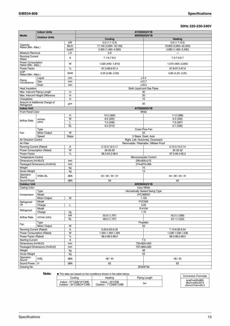
50Hz 220-230-240V
Note: The data are based on the conditions shown in the table below.
ModelIndoor Units ATXS50G2V1B
Outdoor UnitsARXS50G2V1B
Cooling Heating
Capacity Rated (Min.~Max.)
kW 5.0 (1.7~5.3) 5.8 (1.7~6.5)Btu/h 17,100 (5,800~18,100) 19,800 (5,800~22,200)kcal/h 4,300 (1,460~4,560) 4,990 (1,460~5,590)
Moisture Removal L/h 2.8 —Running CurrentRated A 7.1-6.7-6.5 7.3-7.0-6.7
Power Consumption Rated (Min.~Max.) W 1,520 (440~1,810) 1,570 (400~2,000)
Power Factor % 97.3-98.6-97.4 97.8-97.5-97.6COPRated (Min.~Max.) W/W 3.29 (3.86~2.93) 3.69 (4.25~3.25)
Piping Connections
Liquid mm φ 6.4Gas mm φ12.7Drain mm φ18.0
Heat Insulation Both Liquid and Gas PipesMax. Interunit Piping Length m 30Max. Interunit Height Difference m 20Chargeless m 10Amount of Additional Charge of Refrigerant g/m 20
Indoor Unit ATXS50G2V1BFront Panel Color White
Airflow Rate m³/min (cfm)
H 10.2 (360) 11.0 (388)M 8.6 (305) 9.3 (330)L 7.0 (246) 7.6 (267)
SL 6.0 (212) 6.7 (236)
FanType Cross Flow FanMotor Output W 23Speed Steps 5 Steps, Quiet, Auto
Air Direction Control Right, Left, Horizontal, DownwardAir Filter Removable / Washable / Mildew ProofRunning Current (Rated) A 0.12-0.12-0.11 0.15-0.14-0.14Power Consumption (Rated) W 26-26-26 32-32-32Power Factor % 98.5-94.2-98.5 97.0-99.4-95.2Temperature Control Microcomputer ControlDimensions (H×W×D) mm 295×800×215Packaged Dimensions (H×W×D) mm 274×870×366Weight kg 10Gross Weight kg 13Operation Sound H/M/L/SL dBA 43 / 39 / 34 / 31 44 / 39 / 34 / 31
Sound Power dBA 59 60Outdoor Unit ARXS50G2V1BCasing Color Ivory White
CompressorType Hermetically Sealed Swing TypeModel 2YC36BXDMotor Output W 1,100
Refrigerant Oil
Model FVC50KCharge L 0.65
RefrigerantModel R-410ACharge kg 1.70
Airflow Rate m³/min (cfm)HH 50.9 (1,797) 45.0 (1,589)SL 48.9 (1,727) 43.1 (1,522)
FanType PropellerMotor Output W 53
Running Current (Rated) A 6.93-6.63-6.35 7.13-6.82-6.54Power Consumption (Rated) W 1,494-1,494-1,494 1,538-1,538-1,538Power Factor (Rated) % 98.0-98.0-98.0 98.0-98.0-98.0Starting Current A 7.3Dimensions (H×W×D) mm 735×825×300Packaged Dimensions (H×W×D) mm 797×960×390Weight kg 48Gross Weight kg 53Operation Sound H/SL dBA 48 / 44 48 / 45
Sound Power H dBA 62 62Drawing No. 3D059736
Conversion Formulae
kcal/h=kW×860Btu/h=kW×3414
cfm=m³/min×35.3
Cooling Heating Piping Length
Indoor ; 27°CDB/19°CWB Outdoor ; 35°CDB/24°CWB
Indoor ; 20°CDBOutdoor ; 7°CDB/6°CWB 5m
Specifications 13
Specifications SiBE04-808
14 Specifications
SiBE04-808
Printed Circuit Board Connector Wiring Diagram 15
Part 3Printed Circuit Board
Connector Wiring Diagram
1. Printed Circuit Board Connector Wiring Diagram..................................161.1 Indoor Unit..............................................................................................161.2 Outdoor Unit ...........................................................................................18
Printed Circuit Board Connector Wiring Diagram SiBE04-808
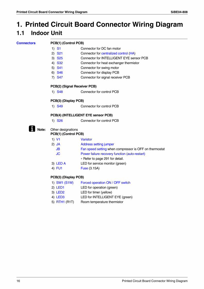
1. Printed Circuit Board Connector Wiring Diagram1.1 Indoor Unit
Connectors PCB(1) (Control PCB)
PCB(2) (Signal Receiver PCB)
PCB(3) (Display PCB)
PCB(4) (INTELLIGENT EYE sensor PCB)
Note: Other designationsPCB(1) (Control PCB)
PCB(3) (Display PCB)
1) S1 Connector for DC fan motor2) S21 Connector for centralized control (HA)3) S25 Connector for INTELLIGENT EYE sensor PCB4) S32 Connector for heat exchanger thermistor5) S41 Connector for swing motor6) S46 Connector for display PCB7) S47 Connector for signal receiver PCB
1) S48 Connector for control PCB
1) S49 Connector for control PCB
1) S26 Connector for control PCB
1) V1 Varistor2) JA Address setting jumper JB Fan speed setting when compressor is OFF on thermostat JC Power failure recovery function (auto-restart) ∗ Refer to page 291 for detail.3) LED A LED for service monitor (green)4) FU1 Fuse (3.15A)
1) SW1 (S1W) Forced operation ON / OFF switch2) LED1 LED for operation (green)3) LED2 LED for timer (yellow)4) LED3 LED for INTELLIGENT EYE (green)5) RTH1 (R1T) Room temperature thermistor
16 Printed Circuit Board Connector Wiring Diagram
SiBE04-808 Printed Circuit Board Connector Wiring Diagram
1
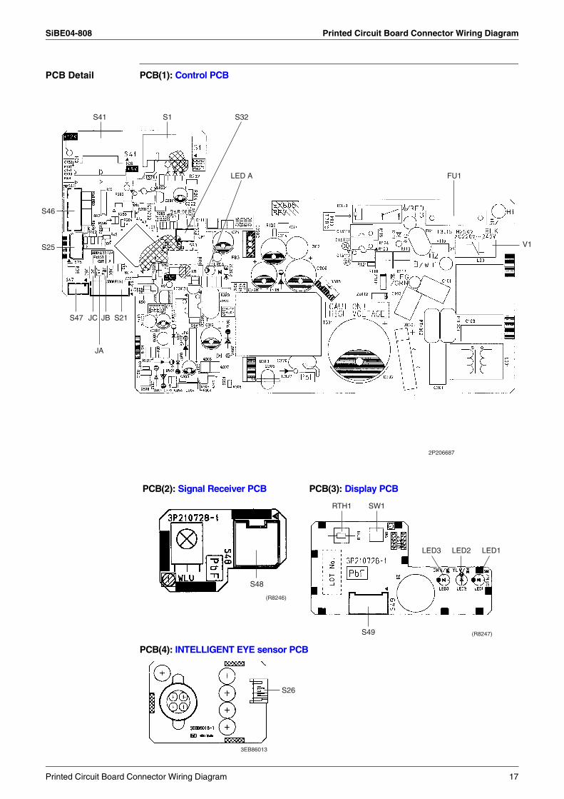
PCB Detail PCB(1): Control PCB
PCB(4): INTELLIGENT EYE sensor PCB
2P206687
S41
S47 JC JB S21
JA
S46
S25
S1 S32
LED A FU1
V
PCB(2): Signal Receiver PCB PCB(3): Display PCB
(R8246)
S48
(R8247)
RTH1 SW1
LED3 LED2 LED1
S49
3EB86013
S26
Printed Circuit Board Connector Wiring Diagram 17
Printed Circuit Board Connector Wiring Diagram SiBE04-808
1.2 Outdoor Unit1.2.1 RK(X)S 20-35 G, ARXS 20-35 G
ConnectorsPCB (1) (Filter PCB)
PCB (2) (Control PCB)
Note: Other designationsPCB (1) (Filter PCB)
PCB (2) (Control PCB)
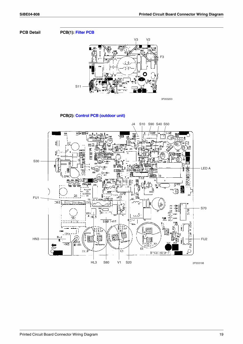
1) S11 Connector for control PCB
1) S10, S50 Connector for filter PCB2) S20 Connector for electronic expansion valve coil3) S30 Connector for compressor motor4) S40 Connector for overload protector5) S70 Connector for fan motor6) S80 Connector for four way valve coil7) S90 Connector for thermistors
(outdoor air, heat exchanger, discharge pipe)8) HL3, HN3 Connector for filter PCB
1) FU3 Fuse (20A)2) V2, V3 Varistor
1) FU1, FU2 Fuse (3.15A)2) LED A Service monitor LED3) V1 Varistor4) J4 Facility setting jumper
∗Refer to page 61 for detail.
18 Printed Circuit Board Connector Wiring Diagram
SiBE04-808 Printed Circuit Board Connector Wiring Diagram
PCB Detail PCB(1): Filter PCB
PCB(2): Control PCB (outdoor unit)
F3
S11
3P203203
V3 V2
S70
S30
HN3
FU1
LED A
FU2
2P203198
S40S90 S50
S20S80 V1HL3
S10J4
Printed Circuit Board Connector Wiring Diagram 19
Printed Circuit Board Connector Wiring Diagram SiBE04-808
1.2.2 RK(X)S 42 G, ARXS 42 G
Connectors PCB (1) (Control PCB)
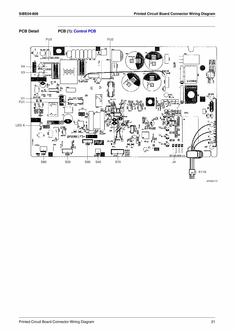
Note: Other DesignationsPCB (1) (Control PCB)
1) S20 Connector for electronic expansion valve coil2) S40 Connector for overload protector3) S70 Connector for fan motor4) S80 Connector for four way valve coil5) S90 Connector for thermistor
(outdoor air, heat exchanger, and discharge pipe)6) X11A Connector for compressor motor
1) LED A Service Monitor LED (Green)2) FU1, FU2 Fuse (3.15A/250V)3) FU3 Fuse (30A/250V)4) J4 Facility setting jumper
*Refer to page 61 for detail.5) V1, V3, V4 Varistor
20 Printed Circuit Board Connector Wiring Diagram
SiBE04-808 Printed Circuit Board Connector Wiring Diagram
PCB Detail PCB (1): Control PCB
FU2FU3
V4
S80 S20 S90 S40 S70 J4
X11A
V3
V1FU1
LED A
2P208173
Printed Circuit Board Connector Wiring Diagram 21
Printed Circuit Board Connector Wiring Diagram SiBE04-808
1.2.3 RK(X)S 50 G, ARXS 50 G
Connectors PCB(1)(Main PCB)
PCB(2)(Service Monitor PCB)
Note: Other DesignationsPCB(1)(Main PCB)
PCB(2)(Service Monitor PCB)
1) S10 Connector for terminal strip (indoor-outdoor transmission)2) S20 Connector for electronic expansion valve coil3) S40 Connector for overload protector4) S51, S101 Connector for service monitor PCB5) S70 Connector for fan motor6) S80 Connector for four way valve coil7) S90 Connector for thermistors
(outdoor air, heat exchanger, and discharge pipe)8) AC1, AC2 Connector for terminal strip (power supply)9) HR1, HR2 Connector for reactor
1) S52, S102 Connector for control PCB
1) FU1 Fuse (30A)2) FU2, FU3 Fuse (3.15A)3) V2, V3, V5
V6, V11Varistor
1) LED A Service monitor LED (green)2) SW1 Forced operation ON/OFF switch3) SW4 Switch A : No function
Switch B : Facility setting switch*Refer to page 61 for detail
Switch C : Defrost operation gets powerful
22 Printed Circuit Board Connector Wiring Diagram
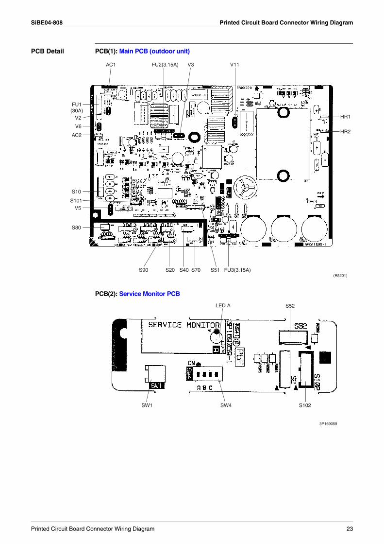
SiBE04-808 Printed Circuit Board Connector Wiring Diagram
PCB Detail PCB(1): Main PCB (outdoor unit)
PCB(2): Service Monitor PCB
V3 V11AC1 FU2(3.15A)
HR1
HR2
FU3(3.15A)(R5201)
S40S20 S70S90 S51
S10
AC2
S101V5
S80
V6
V2
FU1(30A)
S102SW1 SW4
3P169059
LED A S52
Printed Circuit Board Connector Wiring Diagram 23
Printed Circuit Board Connector Wiring Diagram SiBE04-808
24 Printed Circuit Board Connector Wiring Diagram
SiBE04-808
Function and Control 25
Part 4Function and Control
1. Main Functions......................................................................................261.1 Frequency Principle................................................................................261.2 Airflow Direction Control.........................................................................281.3 Fan Speed Control for Indoor Units........................................................291.4 Programme Dry Function .......................................................................301.5 Automatic Operation...............................................................................311.6 Thermostat Control.................................................................................321.7 NIGHT SET Mode ..................................................................................331.8 ECONO Mode ........................................................................................341.9 2 AREA INTELLIGENT EYE ..................................................................351.10 Inverter POWERFUL Operation .............................................................371.11 Other Functions......................................................................................38
2. Function of Thermistor ..........................................................................402.1 Heat Pump Model...................................................................................402.2 Cooling Only Model ................................................................................41
3. Control Specification .............................................................................423.1 Mode Hierarchy ......................................................................................423.2 Frequency Control..................................................................................433.3 Controls at Mode Changing / Start-up....................................................453.4 Discharge Pipe Temperature Control.....................................................483.5 Input Current Control..............................................................................493.6 Freeze-up Protection Control .................................................................503.7 Heating Peak-cut Control .......................................................................513.8 Fan Control.............................................................................................523.9 Liquid Compression Protection Function 2.............................................523.10 Defrost Control .......................................................................................523.11 Electronic Expansion Valve Control .......................................................553.12 Malfunctions ...........................................................................................583.13 Forced Operation Mode .........................................................................593.14 Additional Function.................................................................................603.15 Facility Setting Switch (cooling at low outdoor temperature)..................61
Main Functions SiBE04-808
1. Main FunctionsNote: See the list of functions for the functions applicable to different models.
1.1 Frequency Principle
Main Control Parameters
The compressor is frequency-controlled during normal operation. The target frequency is set by the following 2 parameters coming from the operating indoor unit:
The load condition of the operating indoor unitThe difference between the room temperature and the set temperature
Additional Control Parameters
The target frequency is adapted by additional parameters in the following cases:Frequency restrictionsInitial settingsForced cooling operation
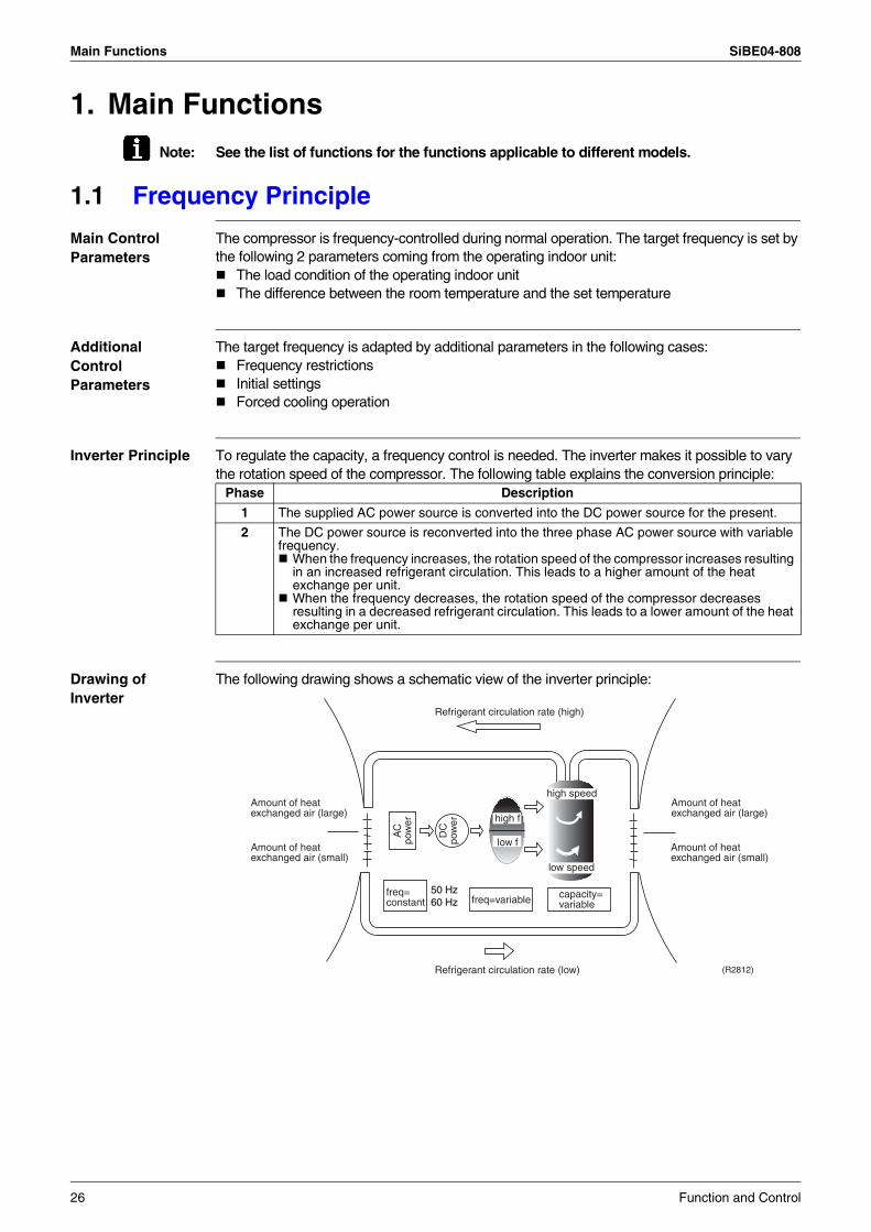
Inverter Principle To regulate the capacity, a frequency control is needed. The inverter makes it possible to vary the rotation speed of the compressor. The following table explains the conversion principle:
Drawing of Inverter
The following drawing shows a schematic view of the inverter principle:
Phase Description
1 The supplied AC power source is converted into the DC power source for the present.
2 The DC power source is reconverted into the three phase AC power source with variable frequency.
When the frequency increases, the rotation speed of the compressor increases resulting in an increased refrigerant circulation. This leads to a higher amount of the heat exchange per unit.When the frequency decreases, the rotation speed of the compressor decreases resulting in a decreased refrigerant circulation. This leads to a lower amount of the heat exchange per unit.
50 Hz60 Hz
Refrigerant circulation rate (high)
Amount of heatexchanged air (large)
Amount of heatexchanged air (small)
AC
pow
er
freq=constant
DC
pow
er
Amount of heatexchanged air (large)
Amount of heatexchanged air (small)
high f
low f
freq=variable capacity=variable
Refrigerant circulation rate (low)
high speed
low speed
(R2812)
26 Function and Control
SiBE04-808 Main Functions
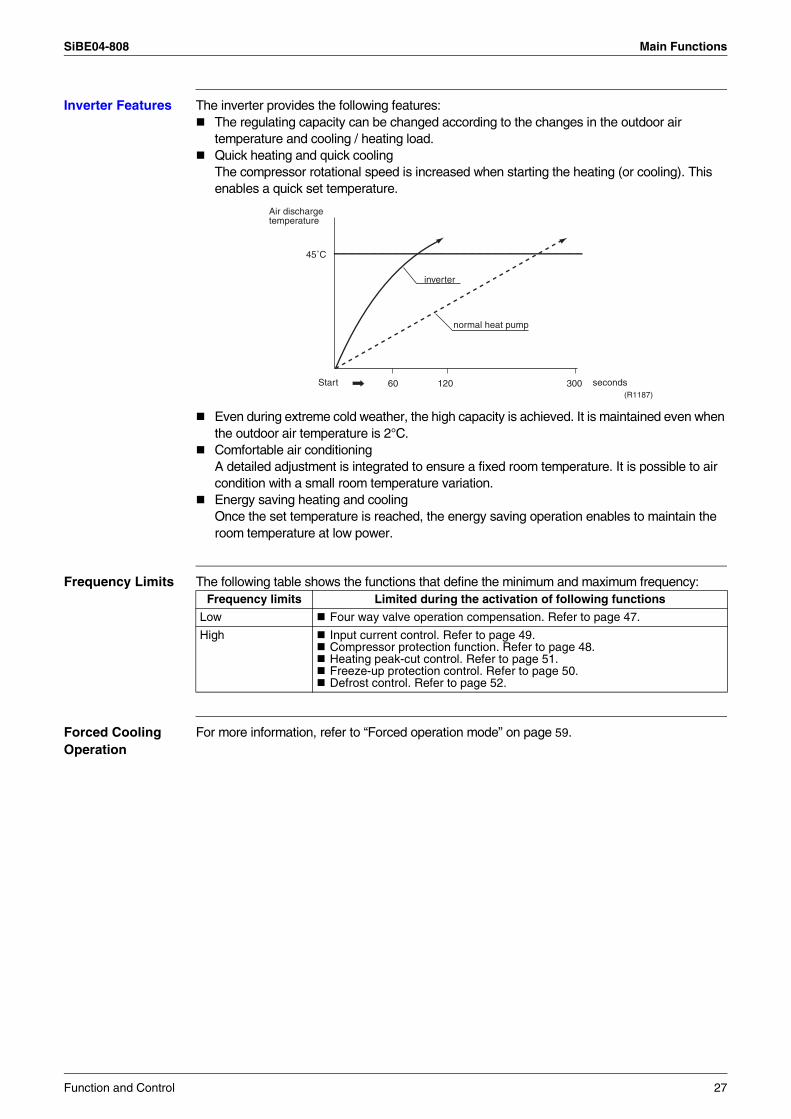
Inverter Features The inverter provides the following features:The regulating capacity can be changed according to the changes in the outdoor air temperature and cooling / heating load.Quick heating and quick coolingThe compressor rotational speed is increased when starting the heating (or cooling). This enables a quick set temperature.
Even during extreme cold weather, the high capacity is achieved. It is maintained even when the outdoor air temperature is 2°C.Comfortable air conditioning A detailed adjustment is integrated to ensure a fixed room temperature. It is possible to air condition with a small room temperature variation.Energy saving heating and coolingOnce the set temperature is reached, the energy saving operation enables to maintain the room temperature at low power.
Frequency Limits The following table shows the functions that define the minimum and maximum frequency:
Forced Cooling Operation
For more information, refer to “Forced operation mode” on page 59.
60 120 300
45˚C
Air dischargetemperature
inverter
normal heat pump
Start seconds(R1187)
Frequency limits Limited during the activation of following functions
Low Four way valve operation compensation. Refer to page 47.
High Input current control. Refer to page 49.Compressor protection function. Refer to page 48.Heating peak-cut control. Refer to page 51.Freeze-up protection control. Refer to page 50.Defrost control. Refer to page 52.
Function and Control 27
Main Functions SiBE04-808
1.2 Airflow Direction Control
Power-Airflow Dual Flaps
The large flaps send a large volume of air downwards to the floor. The flap provides an optimum control area in cooling, heating and dry mode.
Heating ModeDuring heating mode, the large flap enables direct warm air straight downwards. The flap presses the warm air above the floor to reach the entire room.
Cooling ModeDuring cooling mode, the flap retracts into the indoor unit. Then, cool air can be blown far and pervaded all over the room.
Wide-Angle Louvres
The louvres, made of elastic synthetic resin, provide a wide range of airflow that guarantees a comfortable air distribution.
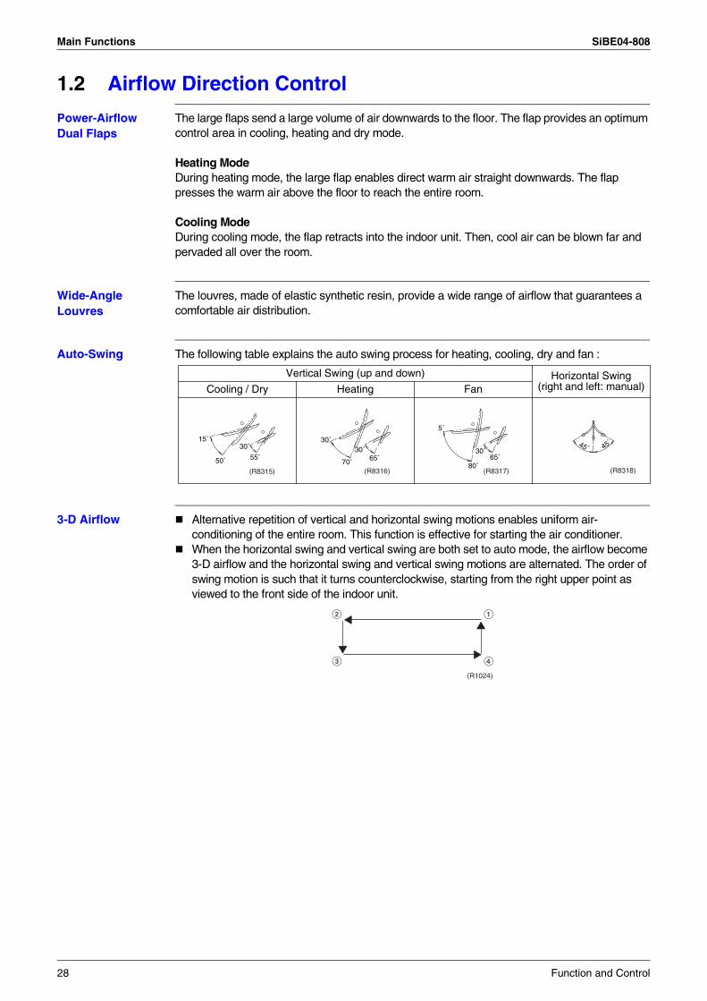
Auto-Swing The following table explains the auto swing process for heating, cooling, dry and fan :
3-D Airflow Alternative repetition of vertical and horizontal swing motions enables uniform air-conditioning of the entire room. This function is effective for starting the air conditioner.When the horizontal swing and vertical swing are both set to auto mode, the airflow become 3-D airflow and the horizontal swing and vertical swing motions are alternated. The order of swing motion is such that it turns counterclockwise, starting from the right upper point as viewed to the front side of the indoor unit.
Vertical Swing (up and down) Horizontal Swing (right and left: manual)Cooling / Dry Heating Fan
15˚
50˚
30˚
55˚
(R8315) (R8316)
30˚
70˚
30˚65˚
(R8317)
5˚
80˚
30˚65˚
(R8318)
45˚45˚
(R1024)
28 Function and Control
SiBE04-808 Main Functions
1.3 Fan Speed Control for Indoor Units
Control Mode The airflow rate can be automatically controlled depending on the difference between the set temperature and the room temperature. This is done through phase control and Hall IC control.
For more information about Hall IC, refer to the troubleshooting for fan motor on page 131.
Phase Steps Phase control and fan speed control contains 9 steps: LLL, LL, SL, L, ML, M, MH, H and HH.In automatic fan speed operation, the step “SL” is not available.
= The airflow rate is automatically controlled within this range when the FAN setting button is set to automatic.
Note: 1. During POWERFUL operation, fan operates H tap + 50 rpm.2. Fan stops during defrost operation.3. In time of thermostat OFF, the fan rotates at the following speed.
Cooling: The fan keeps rotating at the set tap.Heating: The fan keeps rotating at LLL tap.Dry: The fan will stop after keeps rotating for a few minutes at LL tap.
Automatic Airflow Control for Heating
On heating mode, the indoor fan speed will be regulated according to the indoor heat exchanger temperature and the difference between the room temperature and the required set point.
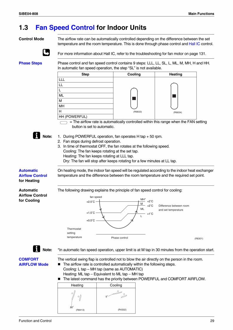
Automatic Airflow Control for Cooling
The following drawing explains the principle of fan speed control for cooling:
Note: *In automatic fan speed operation, upper limit is at M tap in 30 minutes from the operation start.
COMFORT AIRFLOW Mode
The vertical swing flap is controlled not to blow the air directly on the person in the room.The airflow rate is controlled automatically within the following steps.Cooling: L tap – MH tap (same as AUTOMATIC)Heating: ML tap – Equivalent to ML tap – MH tapThe latest command has the priority between POWERFUL and COMFORT AIRFLOW.
Step Cooling Heating
LLL
LL
L
ML
M
MH
H
HH (POWERFUL)
(R6833) (R6834)
+1.5˚C
+2.5˚C
+0.5˚C
+2˚C
+1˚C
M+2˚C
MH*
ML
L
fan speed
Difference between room
and set temperature
Phase control
Thermostat
setting
temperature (R8301)
Heating Cooling
(R8413)80°
(R4302)
5°
Function and Control 29
Main Functions SiBE04-808
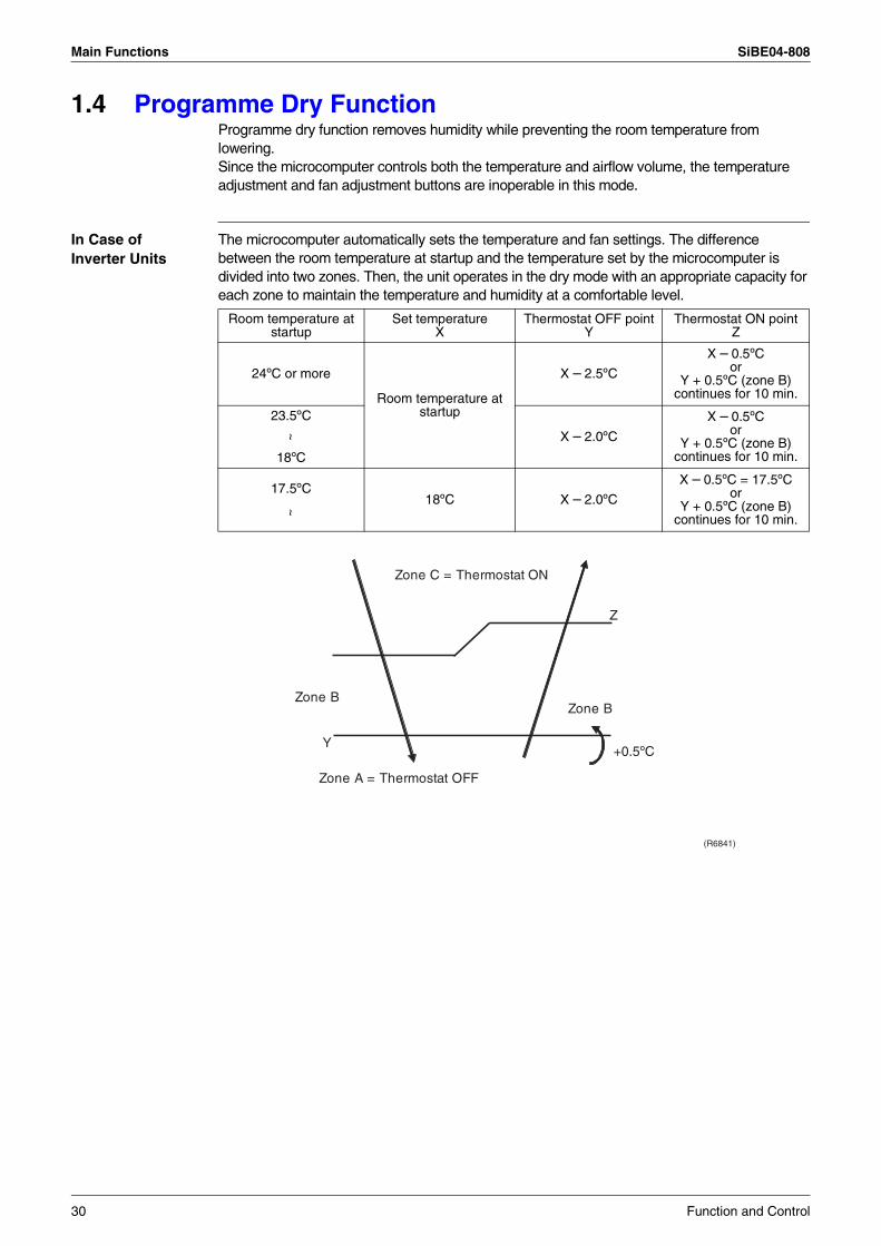
1.4 Programme Dry FunctionProgramme dry function removes humidity while preventing the room temperature from lowering.Since the microcomputer controls both the temperature and airflow volume, the temperature adjustment and fan adjustment buttons are inoperable in this mode.
In Case of Inverter Units
The microcomputer automatically sets the temperature and fan settings. The difference between the room temperature at startup and the temperature set by the microcomputer is divided into two zones. Then, the unit operates in the dry mode with an appropriate capacity for each zone to maintain the temperature and humidity at a comfortable level.
Room temperature at startup
Set temperature X
Thermostat OFF pointY
Thermostat ON pointZ
24ºC or more
Room temperature at startup
X – 2.5ºC
X – 0.5ºCor
Y + 0.5ºC (zone B) continues for 10 min.
23.5ºC
X – 2.0ºC
X – 0.5ºCor
Y + 0.5ºC (zone B) continues for 10 min.
~
18ºC
18ºC X – 2.0ºC
X – 0.5ºC = 17.5ºCor
Y + 0.5ºC (zone B) continues for 10 min.
17.5ºC
~
Z
Y
Zone BZone B
Zone A = Thermostat OFF
Zone C = Thermostat ON
+0.5ºC
(R6841)
30 Function and Control
SiBE04-808 Main Functions
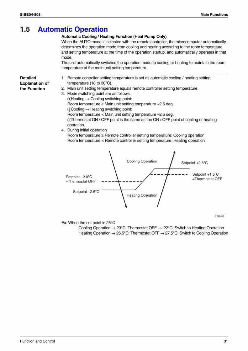
1.5 Automatic OperationAutomatic Cooling / Heating Function (Heat Pump Only)When the AUTO mode is selected with the remote controller, the microcomputer automatically determines the operation mode from cooling and heating according to the room temperature and setting temperature at the time of the operation startup, and automatically operates in that mode.The unit automatically switches the operation mode to cooling or heating to maintain the room temperature at the main unit setting temperature.
Detailed Explanation of the Function
1. Remote controller setting temperature is set as automatic cooling / heating setting temperature (18 to 30°C).
2. Main unit setting temperature equals remote controller setting temperature.3. Mode switching point are as follows.
Heating → Cooling switching point: Room temperature ≥ Main unit setting temperature +2.5 deg. Cooling → Heating switching point: Room temperature < Main unit setting temperature –2.5 deg. Thermostat ON / OFF point is the same as the ON / OFF point of cooling or heating operation.
4. During initial operationRoom temperature ≥ Remote controller setting temperature: Cooling operationRoom temperature < Remote controller setting temperature: Heating operation
Ex: When the set point is 25°CCooling Operation → 23°C: Thermostat OFF → 22°C: Switch to Heating OperationHeating Operation → 26.5°C: Thermostat OFF → 27.5°C: Switch to Cooling Operation
(R6842)
Setpoint +2.5ºC
Setpoint –2.0ºC=Thermostat OFF
Setpoint +1.5ºC=Thermostat OFF
Heating OperationSetpoint –2.5ºC
Cooling Operation
Function and Control 31
Main Functions SiBE04-808
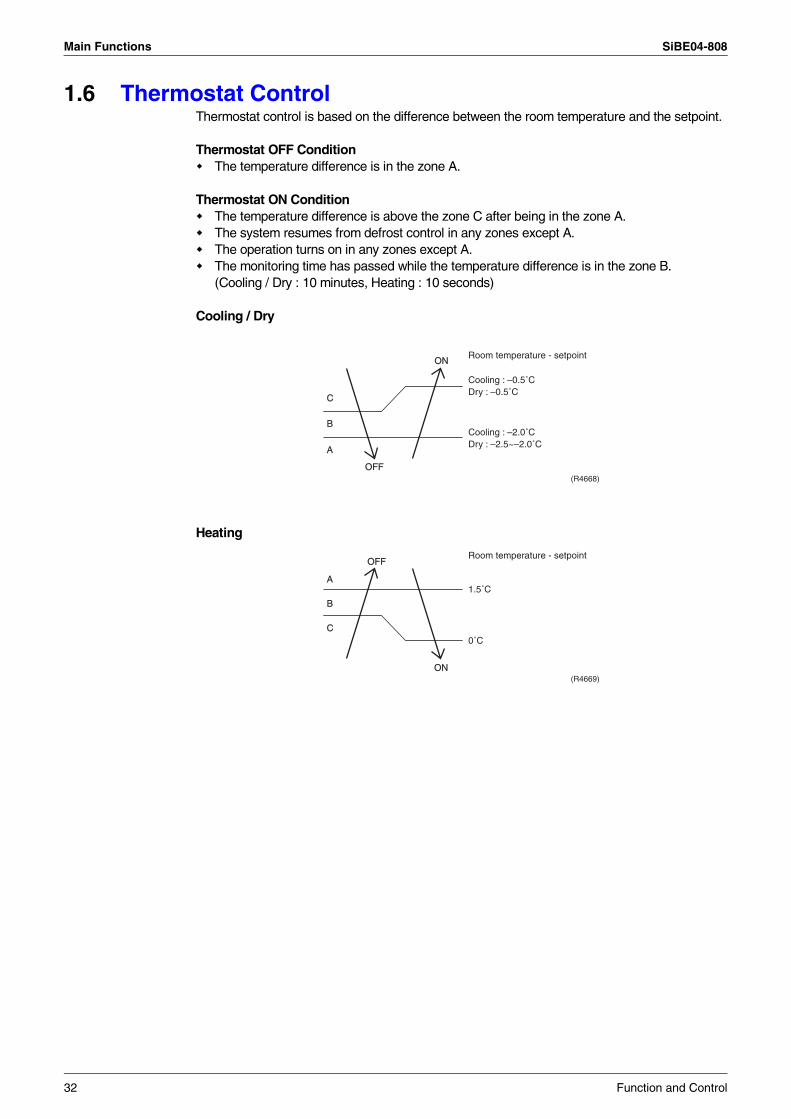
1.6 Thermostat ControlThermostat control is based on the difference between the room temperature and the setpoint.
Thermostat OFF ConditionThe temperature difference is in the zone A.
Thermostat ON ConditionThe temperature difference is above the zone C after being in the zone A.The system resumes from defrost control in any zones except A.The operation turns on in any zones except A.The monitoring time has passed while the temperature difference is in the zone B.(Cooling / Dry : 10 minutes, Heating : 10 seconds)
Cooling / Dry
Heating
B
A
OFF
ON
C
Cooling : –0.5˚CDry : –0.5˚C
Room temperature - setpoint
Cooling : –2.0˚CDry : –2.5~–2.0˚C
(R4668)
B
A
OFF
ON
C
1.5˚C
Room temperature - setpoint
0˚C
(R4669)
32 Function and Control
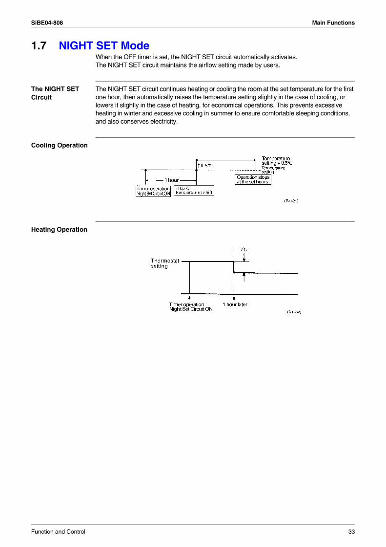
SiBE04-808 Main Functions
1.7 NIGHT SET ModeWhen the OFF timer is set, the NIGHT SET circuit automatically activates.The NIGHT SET circuit maintains the airflow setting made by users.
The NIGHT SET Circuit
The NIGHT SET circuit continues heating or cooling the room at the set temperature for the first one hour, then automatically raises the temperature setting slightly in the case of cooling, or lowers it slightly in the case of heating, for economical operations. This prevents excessive heating in winter and excessive cooling in summer to ensure comfortable sleeping conditions, and also conserves electricity.
Cooling Operation
Heating Operation
Function and Control 33
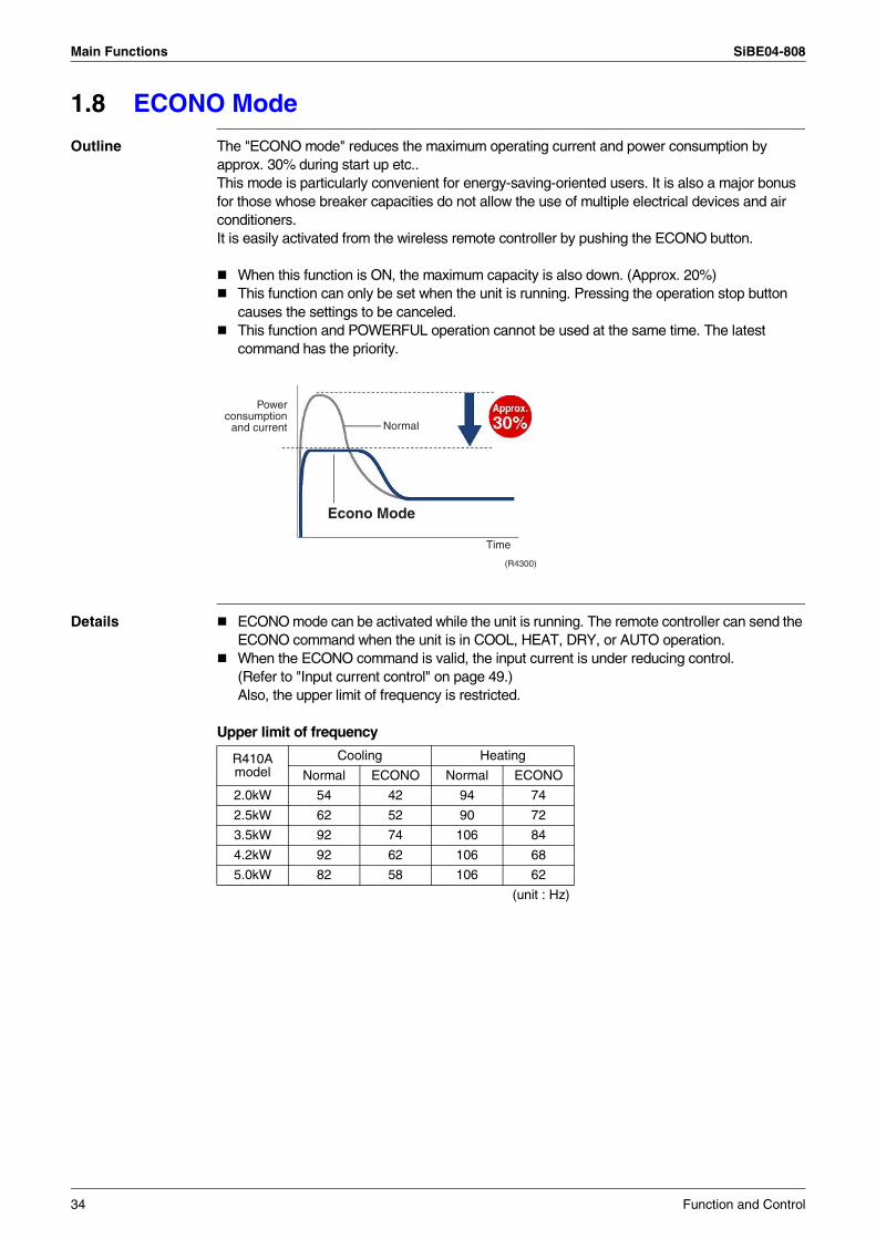
Main Functions SiBE04-808
1.8 ECONO Mode
Outline The "ECONO mode" reduces the maximum operating current and power consumption by approx. 30% during start up etc..This mode is particularly convenient for energy-saving-oriented users. It is also a major bonus for those whose breaker capacities do not allow the use of multiple electrical devices and air conditioners.It is easily activated from the wireless remote controller by pushing the ECONO button.
When this function is ON, the maximum capacity is also down. (Approx. 20%)This function can only be set when the unit is running. Pressing the operation stop button causes the settings to be canceled.This function and POWERFUL operation cannot be used at the same time. The latest command has the priority.
Details ECONO mode can be activated while the unit is running. The remote controller can send the ECONO command when the unit is in COOL, HEAT, DRY, or AUTO operation.When the ECONO command is valid, the input current is under reducing control.(Refer to "Input current control" on page 49.)Also, the upper limit of frequency is restricted.
Upper limit of frequency
Econo Mode
(R4300)
Powerconsumption
and current Normal
Time
R410Amodel
Cooling Heating
Normal ECONO Normal ECONO
2.0kW 54 42 94 74
2.5kW 62 52 90 72
3.5kW 92 74 106 84
4.2kW 92 62 106 68
5.0kW 82 58 106 62
(unit : Hz)
34 Function and Control
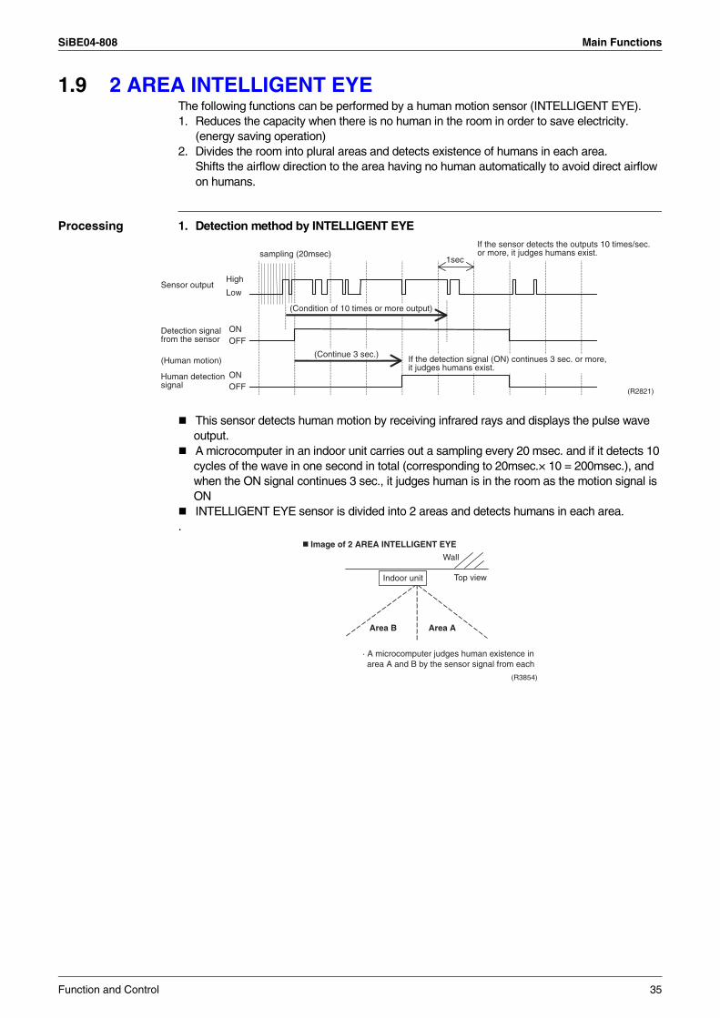
SiBE04-808 Main Functions
1.9 2 AREA INTELLIGENT EYEThe following functions can be performed by a human motion sensor (INTELLIGENT EYE).1. Reduces the capacity when there is no human in the room in order to save electricity.
(energy saving operation)2. Divides the room into plural areas and detects existence of humans in each area.
Shifts the airflow direction to the area having no human automatically to avoid direct airflow on humans.
Processing 1. Detection method by INTELLIGENT EYE
This sensor detects human motion by receiving infrared rays and displays the pulse wave output.A microcomputer in an indoor unit carries out a sampling every 20 msec. and if it detects 10 cycles of the wave in one second in total (corresponding to 20msec.× 10 = 200msec.), and when the ON signal continues 3 sec., it judges human is in the room as the motion signal is ONINTELLIGENT EYE sensor is divided into 2 areas and detects humans in each area.
.
If the sensor detects the outputs 10 times/sec. or more, it judges humans exist.
1secsampling (20msec)
High
Low
ONOFF
Sensor output
(Human motion)
Human detectionsignal
ONOFF
Detection signal from the sensor
(R2821)
(Condition of 10 times or more output)
(Continue 3 sec.)If the detection signal (ON) continues 3 sec. or more, it judges humans exist.
Image of 2 AREA INTELLIGENT EYE
Top view
(R3854)
Indoor unit
Wall
Area AArea B
· A microcomputer judges human existence inarea A and B by the sensor signal from each
Function and Control 35
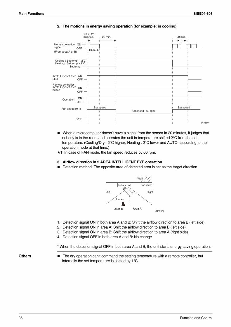
Main Functions SiBE04-808
2. The motions in energy saving operation (for example: in cooling)
When a microcomputer doesn’t have a signal from the sensor in 20 minutes, it judges that nobody is in the room and operates the unit in temperature shifted 2°C from the set temperature. (Cooling/Dry : 2°C higher, Heating : 2°C lower and AUTO : according to the operation mode at that time.)
1 In case of FAN mode, the fan speed reduces by 60 rpm.
3. Airflow direction in 2 AREA INTELLIGENT EYE operationDetection method: The opposite area of detected area is set as the target direction.
1. Detection signal ON in both area A and B: Shift the airflow direction to area B (left side)2. Detection signal ON in area A: Shift the airflow direction to area B (left side)3. Detection signal ON in area B: Shift the airflow direction to area A (right side)4. Detection signal OFF in both area A and B: No change
* When the detection signal OFF in both area A and B, the unit starts energy saving operation.
Others The dry operation can’t command the setting temperature with a remote controller, but internally the set temperature is shifted by 1°C.
ONOFF RESET.
Cooling : Set temp. + 2˚CHeating : Set temp. - 2˚C
Human detectionsignal
(From area A or B)
20 min. 20 min.within 20minutes.
ONOFF
ONOFF
Operation
OFF
Fan speed ( 1)Set speed - 60 rpm
Set speed Set speed
Set temp.
(R8350)
Remote controller INTELLIGENT EYE button
ONOFF
INTELLIGENT EYE LED
Top view
Wall
Indoor unit
Area AArea B
Left Right
Human
(R3853)
36 Function and Control
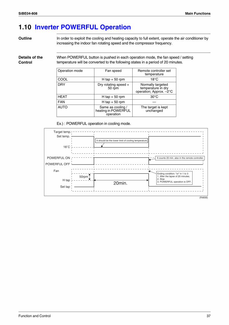
SiBE04-808 Main Functions
1.10 Inverter POWERFUL Operation
Outline In order to exploit the cooling and heating capacity to full extent, operate the air conditioner by increasing the indoor fan rotating speed and the compressor frequency.
Details of the Control
When POWERFUL button is pushed in each operation mode, the fan speed / setting temperature will be converted to the following states in a period of 20 minutes.
Ex.) : POWERFUL operation in cooling mode.
Operation mode Fan speed Remote controller set temperature
COOL H tap + 50 rpm 18°C
DRY Dry rotating speed + 50 rpm
Normally targeted temperature in dry
operation; Approx. –2°C
HEAT H tap + 50 rpm 30°C
FAN H tap + 50 rpm —
AUTO Same as cooling /heating in POWERFUL
operation
The target is kept unchanged
(R4606)
Target temp.
Fan
50rpm
Set temp.
18˚C
POWERFUL ON
POWERFUL OFF
H tap
Set tap
It should be the lower limit of cooling temperature.
It counts 20 min. also in the remote controller.
20min.
Ending condition: "or" in 1 to 31. After the lapse of 20 minutes.2. Stop3. POWERFUL operation is OFF.
Function and Control 37
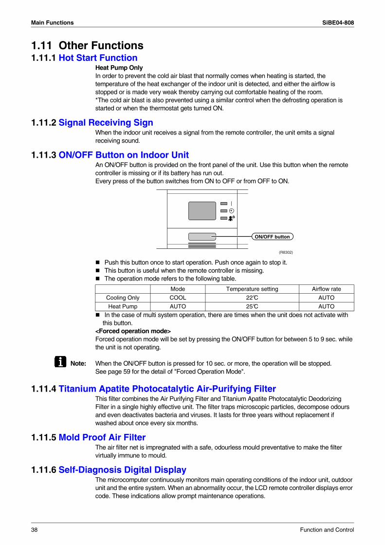
Main Functions SiBE04-808
1.11 Other Functions1.11.1 Hot Start Function
Heat Pump OnlyIn order to prevent the cold air blast that normally comes when heating is started, the temperature of the heat exchanger of the indoor unit is detected, and either the airflow is stopped or is made very weak thereby carrying out comfortable heating of the room.*The cold air blast is also prevented using a similar control when the defrosting operation is started or when the thermostat gets turned ON.
1.11.2 Signal Receiving SignWhen the indoor unit receives a signal from the remote controller, the unit emits a signal receiving sound.
1.11.3 ON/OFF Button on Indoor UnitAn ON/OFF button is provided on the front panel of the unit. Use this button when the remote controller is missing or if its battery has run out. Every press of the button switches from ON to OFF or from OFF to ON.
Push this button once to start operation. Push once again to stop it.This button is useful when the remote controller is missing.The operation mode refers to the following table.
In the case of multi system operation, there are times when the unit does not activate with this button.
<Forced operation mode>Forced operation mode will be set by pressing the ON/OFF button for between 5 to 9 sec. while the unit is not operating.
Note: When the ON/OFF button is pressed for 10 sec. or more, the operation will be stopped.See page 59 for the detail of "Forced Operation Mode".
1.11.4 Titanium Apatite Photocatalytic Air-Purifying FilterThis filter combines the Air Purifying Filter and Titanium Apatite Photocatalytic Deodorizing Filter in a single highly effective unit. The filter traps microscopic particles, decompose odours and even deactivates bacteria and viruses. It lasts for three years without replacement if washed about once every six months.
1.11.5 Mold Proof Air FilterThe air filter net is impregnated with a safe, odourless mould preventative to make the filter virtually immune to mould.
1.11.6 Self-Diagnosis Digital DisplayThe microcomputer continuously monitors main operating conditions of the indoor unit, outdoor unit and the entire system. When an abnormality occur, the LCD remote controller displays error code. These indications allow prompt maintenance operations.
(R8302)
ON/OFF button
Mode Temperature setting Airflow rate
Cooling Only COOL 22°C AUTO
Heat Pump AUTO 25°C AUTO
38 Function and Control
SiBE04-808 Main Functions
1.11.7 Auto-restart FunctionEven if a power failure (including one for just a moment) occurs during the operation, the operation restarts in the condition before power failure automatically when power is restored.(Note) It takes 3 minutes to restart the operation because the 3-minutes standby function is activated.
1.11.8 WEEKLY TIMER OperationUp to 4 timer settings can be saved for each day of the week (up to 28 settings in total). Those 3 items of “ON / OFF”, “temperature” and “time” can be set.
Refer to “WEEKLY TIMER Operation” on page 85 for detail.
Function and Control 39
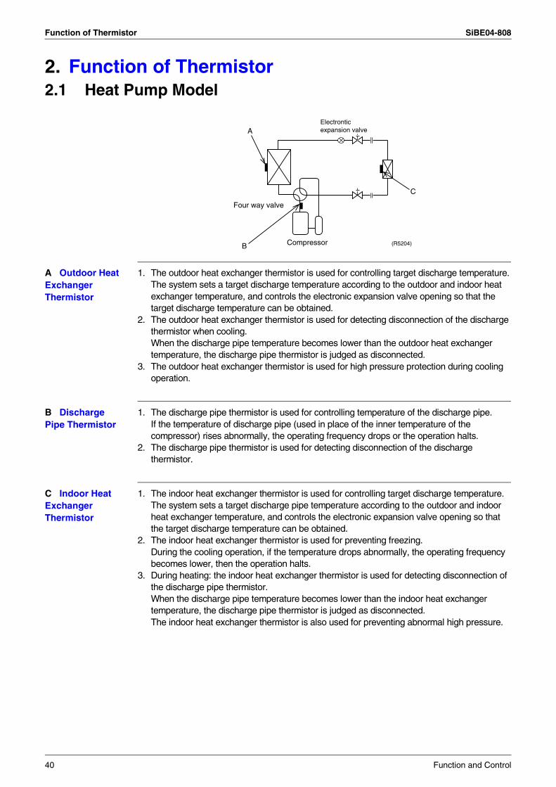
Function of Thermistor SiBE04-808
2. Function of Thermistor2.1 Heat Pump Model
A Outdoor Heat Exchanger Thermistor
1. The outdoor heat exchanger thermistor is used for controlling target discharge temperature.The system sets a target discharge temperature according to the outdoor and indoor heat exchanger temperature, and controls the electronic expansion valve opening so that the target discharge temperature can be obtained.
2. The outdoor heat exchanger thermistor is used for detecting disconnection of the discharge thermistor when cooling.When the discharge pipe temperature becomes lower than the outdoor heat exchanger temperature, the discharge pipe thermistor is judged as disconnected.
3. The outdoor heat exchanger thermistor is used for high pressure protection during cooling operation.
B Discharge Pipe Thermistor
1. The discharge pipe thermistor is used for controlling temperature of the discharge pipe.If the temperature of discharge pipe (used in place of the inner temperature of the compressor) rises abnormally, the operating frequency drops or the operation halts.
2. The discharge pipe thermistor is used for detecting disconnection of the discharge thermistor.
C Indoor Heat Exchanger Thermistor
1. The indoor heat exchanger thermistor is used for controlling target discharge temperature.The system sets a target discharge pipe temperature according to the outdoor and indoor heat exchanger temperature, and controls the electronic expansion valve opening so that the target discharge temperature can be obtained.
2. The indoor heat exchanger thermistor is used for preventing freezing.During the cooling operation, if the temperature drops abnormally, the operating frequency becomes lower, then the operation halts.
3. During heating: the indoor heat exchanger thermistor is used for detecting disconnection of the discharge pipe thermistor.When the discharge pipe temperature becomes lower than the indoor heat exchanger temperature, the discharge pipe thermistor is judged as disconnected.The indoor heat exchanger thermistor is also used for preventing abnormal high pressure.
Four way valve
Compressor (R5204)
A
C
B
Electronticexpansion valve
40 Function and Control
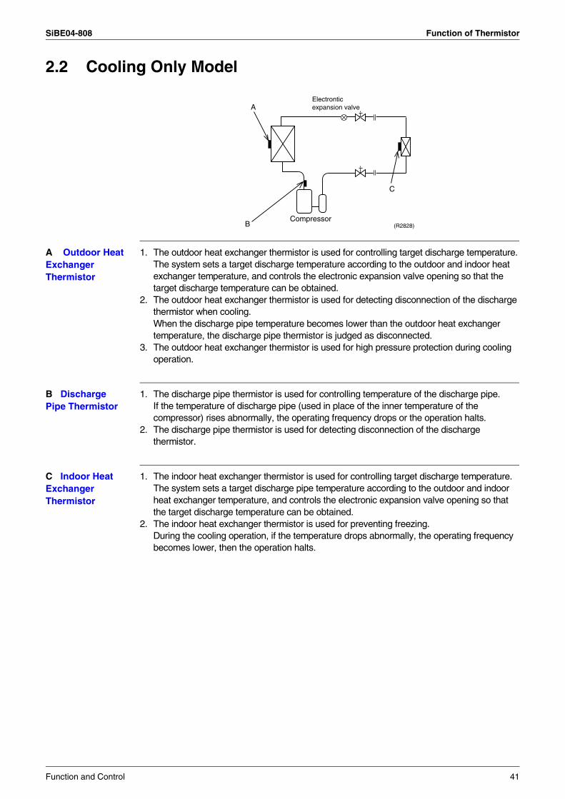
SiBE04-808 Function of Thermistor
2.2 Cooling Only Model
A Outdoor Heat Exchanger Thermistor
1. The outdoor heat exchanger thermistor is used for controlling target discharge temperature.The system sets a target discharge temperature according to the outdoor and indoor heat exchanger temperature, and controls the electronic expansion valve opening so that the target discharge temperature can be obtained.
2. The outdoor heat exchanger thermistor is used for detecting disconnection of the discharge thermistor when cooling.When the discharge pipe temperature becomes lower than the outdoor heat exchanger temperature, the discharge pipe thermistor is judged as disconnected.
3. The outdoor heat exchanger thermistor is used for high pressure protection during cooling operation.
B Discharge Pipe Thermistor
1. The discharge pipe thermistor is used for controlling temperature of the discharge pipe.If the temperature of discharge pipe (used in place of the inner temperature of the compressor) rises abnormally, the operating frequency drops or the operation halts.
2. The discharge pipe thermistor is used for detecting disconnection of the discharge thermistor.
C Indoor Heat Exchanger Thermistor
1. The indoor heat exchanger thermistor is used for controlling target discharge temperature.The system sets a target discharge pipe temperature according to the outdoor and indoor heat exchanger temperature, and controls the electronic expansion valve opening so that the target discharge temperature can be obtained.
2. The indoor heat exchanger thermistor is used for preventing freezing.During the cooling operation, if the temperature drops abnormally, the operating frequency becomes lower, then the operation halts.
A
C
BCompressor
(R2828)
Electronticexpansion valve
Function and Control 41
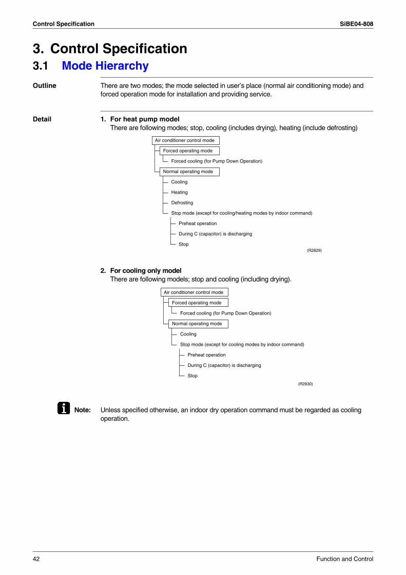
Control Specification SiBE04-808
3. Control Specification3.1 Mode Hierarchy
Outline There are two modes; the mode selected in user’s place (normal air conditioning mode) and forced operation mode for installation and providing service.
Detail 1. For heat pump modelThere are following modes; stop, cooling (includes drying), heating (include defrosting)
2. For cooling only model There are following models; stop and cooling (including drying).
Note: Unless specified otherwise, an indoor dry operation command must be regarded as cooling operation.
Air conditioner control mode
Forced operating mode
Forced cooling (for Pump Down Operation)
Normal operating mode
Cooling
Heating
Defrosting
Stop mode (except for cooling/heating modes by indoor command)
Preheat operation
During C (capacitor) is discharging
Stop(R2829)
Air conditioner control mode
Forced operating mode
Forced cooling (for Pump Down Operation)
Normal operating mode
Cooling
Stop mode (except for cooling modes by indoor command)
Preheat operation
During C (capacitor) is discharging
Stop
(R2830)
42 Function and Control
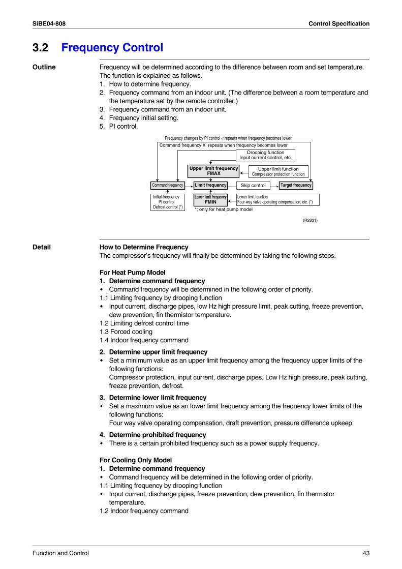
SiBE04-808 Control Specification
3.2 Frequency Control
Outline Frequency will be determined according to the difference between room and set temperature. The function is explained as follows.1. How to determine frequency.2. Frequency command from an indoor unit. (The difference between a room temperature and
the temperature set by the remote controller.)3. Frequency command from an indoor unit.4. Frequency initial setting.5. PI control.
Detail How to Determine FrequencyThe compressor’s frequency will finally be determined by taking the following steps.
For Heat Pump Model1. Determine command frequency
Command frequency will be determined in the following order of priority.1.1 Limiting frequency by drooping function
Input current, discharge pipes, low Hz high pressure limit, peak cutting, freeze prevention, dew prevention, fin thermistor temperature.
1.2 Limiting defrost control time1.3 Forced cooling1.4 Indoor frequency command
2. Determine upper limit frequencySet a minimum value as an upper limit frequency among the frequency upper limits of the following functions: Compressor protection, input current, discharge pipes, Low Hz high pressure, peak cutting, freeze prevention, defrost.
3. Determine lower limit frequencySet a maximum value as an lower limit frequency among the frequency lower limits of the following functions: Four way valve operating compensation, draft prevention, pressure difference upkeep.
4. Determine prohibited frequencyThere is a certain prohibited frequency such as a power supply frequency.
For Cooling Only Model1. Determine command frequency
Command frequency will be determined in the following order of priority.1.1 Limiting frequency by drooping function
Input current, discharge pipes, freeze prevention, dew prevention, fin thermistor temperature.
1.2 Indoor frequency command
Command frequency Limit frequency Skip control
Upper limit functionCompressor protection function
Lower limit functionFour-way valve operating compensation, etc. (*)
Initial frequency PI control
Defrost control (*)
Drooping functionInput current control, etc.
Upper limit frequencyFMAX
Lower limit frequencyFMIN
Target frequency
Command frequency X repeats when frequency becomes lower
Frequency changes by PI control < repeats when frequency becomes lower
*; only for heat pump model
(R2831)
Function and Control 43
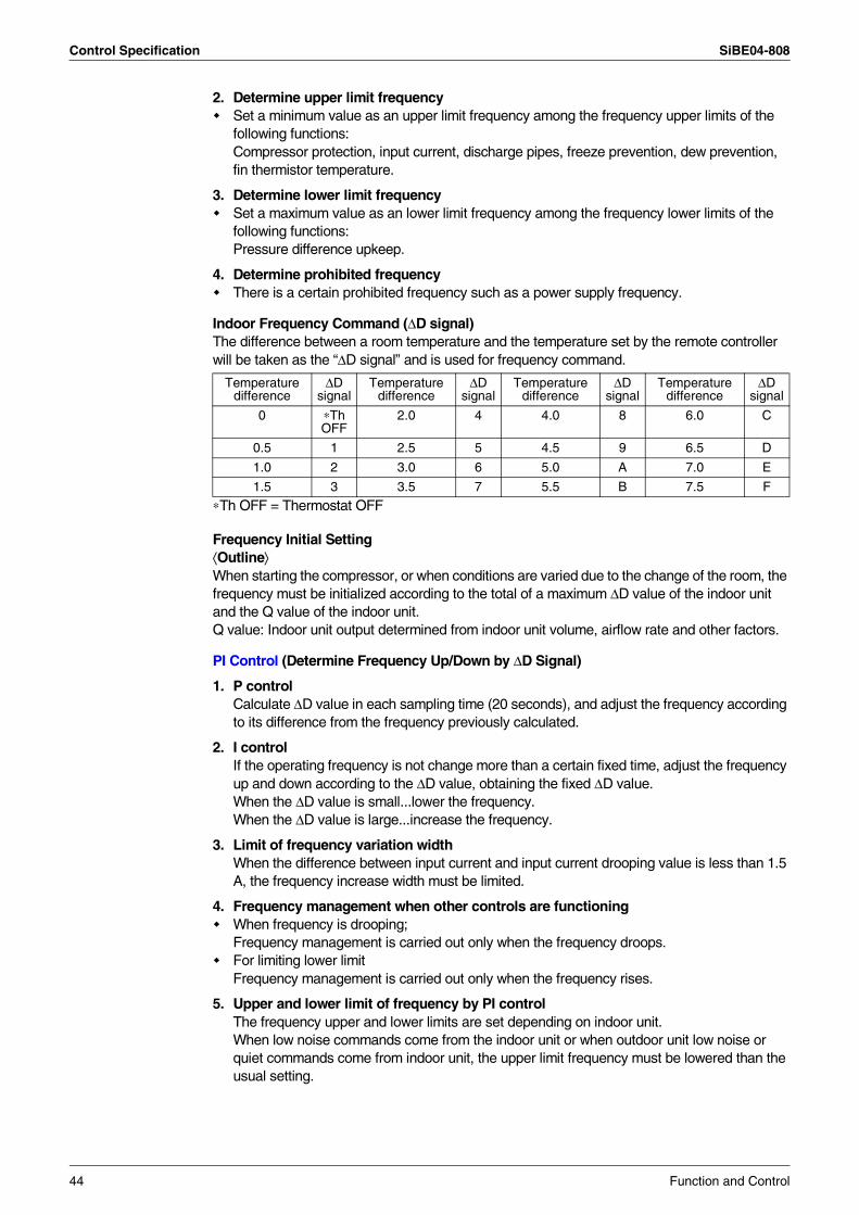
Control Specification SiBE04-808
2. Determine upper limit frequencySet a minimum value as an upper limit frequency among the frequency upper limits of the following functions: Compressor protection, input current, discharge pipes, freeze prevention, dew prevention, fin thermistor temperature.
3. Determine lower limit frequencySet a maximum value as an lower limit frequency among the frequency lower limits of the following functions: Pressure difference upkeep.
4. Determine prohibited frequencyThere is a certain prohibited frequency such as a power supply frequency.
Indoor Frequency Command (∆D signal)The difference between a room temperature and the temperature set by the remote controller will be taken as the “∆D signal” and is used for frequency command.
∗Th OFF = Thermostat OFF
Frequency Initial Setting⟨Outline⟩When starting the compressor, or when conditions are varied due to the change of the room, the frequency must be initialized according to the total of a maximum ∆D value of the indoor unit and the Q value of the indoor unit.Q value: Indoor unit output determined from indoor unit volume, airflow rate and other factors.
PI Control (Determine Frequency Up/Down by ∆D Signal)
1. P controlCalculate ∆D value in each sampling time (20 seconds), and adjust the frequency according to its difference from the frequency previously calculated.
2. I controlIf the operating frequency is not change more than a certain fixed time, adjust the frequency up and down according to the ∆D value, obtaining the fixed ∆D value.When the ∆D value is small...lower the frequency.When the ∆D value is large...increase the frequency.
3. Limit of frequency variation widthWhen the difference between input current and input current drooping value is less than 1.5 A, the frequency increase width must be limited.
4. Frequency management when other controls are functioningWhen frequency is drooping; Frequency management is carried out only when the frequency droops.For limiting lower limit Frequency management is carried out only when the frequency rises.
5. Upper and lower limit of frequency by PI control The frequency upper and lower limits are set depending on indoor unit.When low noise commands come from the indoor unit or when outdoor unit low noise or quiet commands come from indoor unit, the upper limit frequency must be lowered than the usual setting.
Temperature difference
∆D signal
Temperature difference
∆D signal
Temperature difference
∆D signal
Temperature difference
∆D signal
0 ∗Th OFF
2.0 4 4.0 8 6.0 C
0.5 1 2.5 5 4.5 9 6.5 D
1.0 2 3.0 6 5.0 A 7.0 E
1.5 3 3.5 7 5.5 B 7.5 F
44 Function and Control
SiBE04-808 Control Specification
3.3 Controls at Mode Changing / Start-up3.3.1 Preheating Operation
Outline Operate the inverter in the open phase operation with the conditions including the preheating command, outdoor air temperature and discharge pipe temperature from the indoor side.
Detail 20/25/35 classOutside temperature ≥ 10°C → Control A (preheating for normal state)Outside temperature < 10°C → Control B (preheating of increased capacity)
Control AON condition
Discharge pipe temperature < 10°CFin temperature < 85°C
OFF conditionDischarge pipe temperature > 12°CFin temperature ≥ 90°C
Control BON condition
Discharge pipe temperature < 20°CFin temperature < 85°C
OFF conditionDischarge pipe temperature > 22°CFin temperature ≥ 90°C
42 classPreheating ON Condition
When the discharge pipe temperature is below 10ºC, inverter in open phase operation starts.
OFF ConditionWhen the discharge pipe temperature is higher than 12ºC, inverter in open phase operation stops.
50 classOutside temperature ≥ 10°C → Control A (preheating for normal state)Outside temperature < 10°C → Control B (preheating of increased capacity)
Control AON condition
Discharge pipe temperature < 6°CFin temperature < 85°C
OFF conditionDischarge pipe temperature > 8°CFin temperature ≥ 90°C
Control BON condition
Discharge pipe temperature < 10.5°CFin temperature < 85°C
OFF conditionDischarge pipe temperature > 12°CFin temperature ≥ 90°C
Note: The power consumption of compressor during preheat operation is 35 W.
Function and Control 45
Control Specification SiBE04-808
3.3.2 Four Way Valve Switching
Outline During the heating operation current must be conducted and during cooling and defrosting current must not be conducted. In order to eliminate the switching sound (as the four way valve coil switches from ON to OFF) when the heating is stopped, the delay switch of the four way valve must be carried out after the operation stopped.
Detail The OFF delay of four way valve Energize the coil for 160 sec (20/25/35 class) or 150 sec (42/50 class) after unit operation is stopped.
46 Function and Control
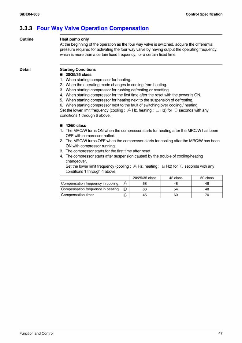
SiBE04-808 Control Specification
3.3.3 Four Way Valve Operation Compensation
Outline Heat pump onlyAt the beginning of the operation as the four way valve is switched, acquire the differential pressure required for activating the four way valve by having output the operating frequency, which is more than a certain fixed frequency, for a certain fixed time.
Detail Starting Conditions20/25/35 class
1. When starting compressor for heating.2. When the operating mode changes to cooling from heating.3. When starting compressor for rushing defrosting or resetting.4. When starting compressor for the first time after the reset with the power is ON.5. When starting compressor for heating next to the suspension of defrosting.6. When starting compressor next to the fault of switching over cooling / heating.Set the lower limit frequency (cooling : Hz, heating : Hz) for seconds with any conditions 1 through 6 above.
42/50 class1. The MRC/W turns ON when the compressor starts for heating after the MRC/W has been
OFF with compressor halted.2. The MRC/W turns OFF when the compressor starts for cooling after the MRC/W has been
ON with compressor running.3. The compressor starts for the first time after reset.4. The compressor starts after suspension caused by the trouble of cooling/heating
changeover.Set the lower limit frequency (cooling : Hz, heating : Hz) for seconds with any conditions 1 through 4 above.
20/25/35 class 42 class 50 class
Compensation frequency in cooling 68 48 48
Compensation frequency in heating 66 54 48
Compensation timer 45 60 70
Function and Control 47
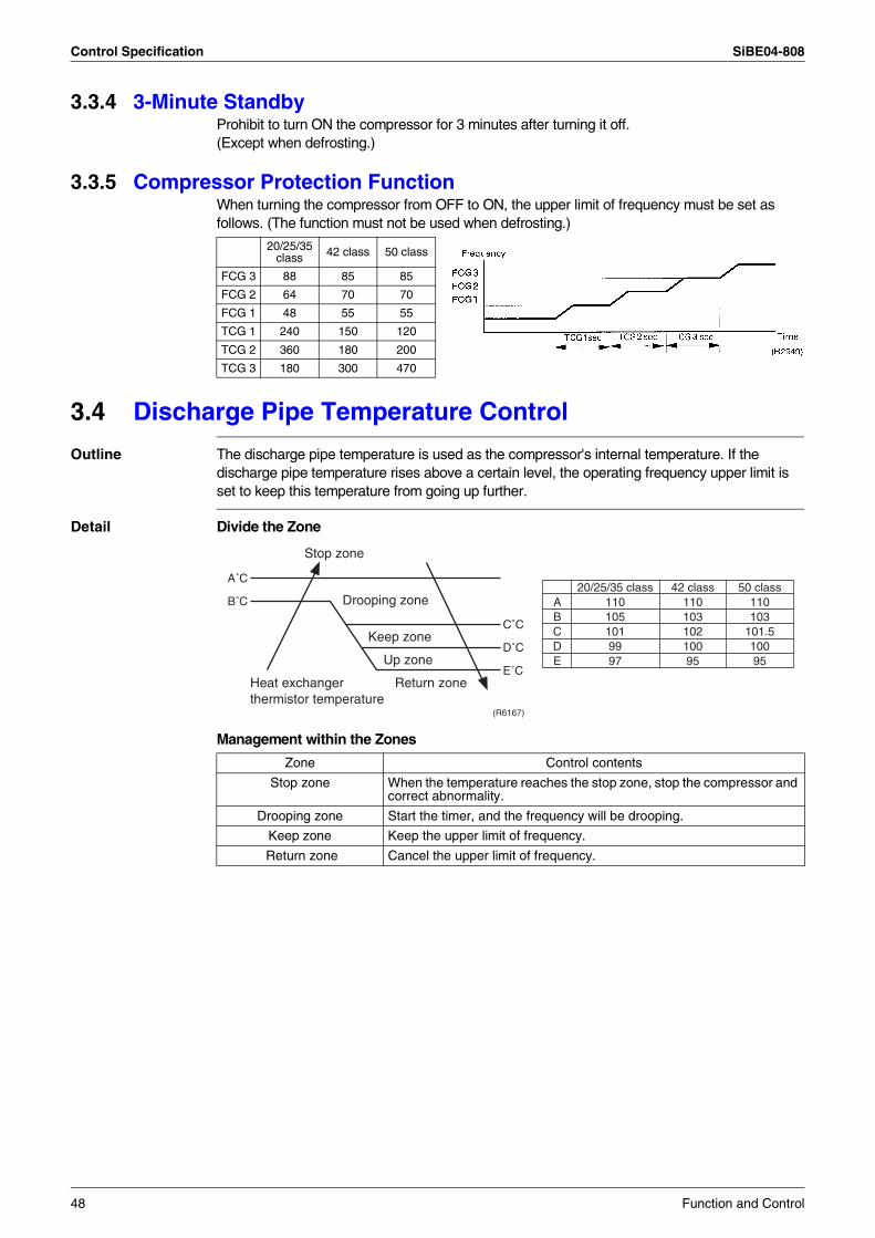
Control Specification SiBE04-808
3.3.4 3-Minute StandbyProhibit to turn ON the compressor for 3 minutes after turning it off.(Except when defrosting.)
3.3.5 Compressor Protection FunctionWhen turning the compressor from OFF to ON, the upper limit of frequency must be set as follows. (The function must not be used when defrosting.)
3.4 Discharge Pipe Temperature Control
Outline The discharge pipe temperature is used as the compressor's internal temperature. If the discharge pipe temperature rises above a certain level, the operating frequency upper limit is set to keep this temperature from going up further.
Detail Divide the Zone
Management within the Zones
20/25/35 class 42 class 50 class
FCG 3 88 85 85
FCG 2 64 70 70
FCG 1 48 55 55
TCG 1 240 150 120
TCG 2 360 180 200
TCG 3 180 300 470
Zone Control contents
Stop zone When the temperature reaches the stop zone, stop the compressor and correct abnormality.
Drooping zone Start the timer, and the frequency will be drooping.
Keep zone Keep the upper limit of frequency.
Return zone Cancel the upper limit of frequency.
A˚C
B˚C
C˚C
D˚C
E˚C
(R6167)
ABCDE
20/25/35 class1101051019997
42 class11010310210095
50 class110103
101.510095
Stop zone
Drooping zone
Keep zone
Up zone
Return zoneHeat exchanger thermistor temperature
48 Function and Control
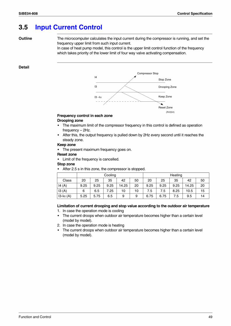
SiBE04-808 Control Specification
3.5 Input Current Control
Outline The microcomputer calculates the input current during the compressor is running, and set the frequency upper limit from such input current.In case of heat pump model, this control is the upper limit control function of the frequency which takes priority of the lower limit of four way valve activating compensation.
Detail
Frequency control in each zoneDrooping zone
The maximum limit of the compressor frequency in this control is defined as operation frequency – 2Hz.After this, the output frequency is pulled down by 2Hz every second until it reaches the steady zone.
Keep zoneThe present maximum frequency goes on.
Reset zoneLimit of the frequency is cancelled.
Stop zoneAfter 2.5 s in this zone, the compressor is stopped.
Limitation of current drooping and stop value according to the outdoor air temperature1. In case the operation mode is cooling
The current droops when outdoor air temperature becomes higher than a certain level (model by model).
2. In case the operation mode is heatingThe current droops when outdoor air temperature becomes higher than a certain level (model by model).
Cooling Heating
Class 20 25 35 42 50 20 25 35 42 50
I4 (A) 9.25 9.25 9.25 14.25 20 9.25 9.25 9.25 14.25 20
I3 (A) 6 6.5 7.25 10 10 7.5 7.5 8.25 10.5 15
I3-Iα (A) 5.25 5.75 6.5 9 9 6.75 6.75 7.5 9.5 14
Compressor Stop
Drooping Zone
Stop Zone
Keep Zone
Reset Zone
I4
I3
I3 –Iα
(R4304)
Function and Control 49
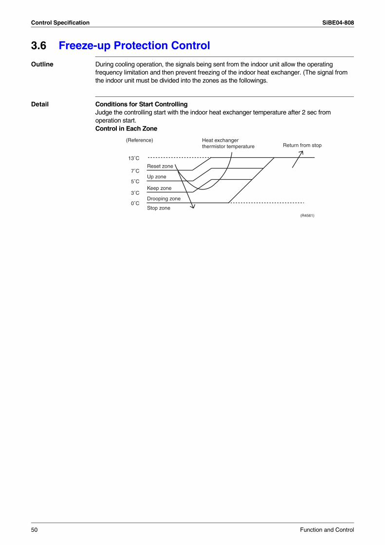
Control Specification SiBE04-808
3.6 Freeze-up Protection Control
Outline During cooling operation, the signals being sent from the indoor unit allow the operating frequency limitation and then prevent freezing of the indoor heat exchanger. (The signal from the indoor unit must be divided into the zones as the followings.
Detail Conditions for Start ControllingJudge the controlling start with the indoor heat exchanger temperature after 2 sec from operation start.Control in Each Zone
(R4561)
Return from stop(Reference)
Reset zone
Heat exchangerthermistor temperature
Up zone
Keep zone
Drooping zone
Stop zone0˚C
3˚C
5˚C
7˚C
13˚C
50 Function and Control
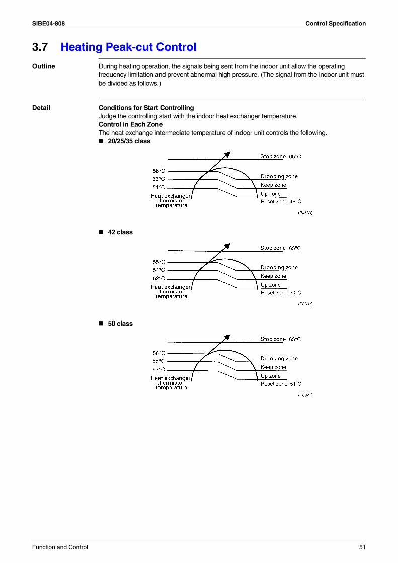
SiBE04-808 Control Specification
3.7 Heating Peak-cut Control
Outline During heating operation, the signals being sent from the indoor unit allow the operating frequency limitation and prevent abnormal high pressure. (The signal from the indoor unit must be divided as follows.)
Detail Conditions for Start ControllingJudge the controlling start with the indoor heat exchanger temperature.Control in Each ZoneThe heat exchange intermediate temperature of indoor unit controls the following.
20/25/35 class
42 class
50 class
Function and Control 51
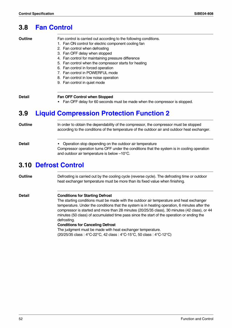
Control Specification SiBE04-808
3.8 Fan Control
Outline Fan control is carried out according to the following conditions.1. Fan ON control for electric component cooling fan2. Fan control when defrosting3. Fan OFF delay when stopped 4. Fan control for maintaining pressure difference5. Fan control when the compressor starts for heating 6. Fan control in forced operation 7. Fan control in POWERFUL mode8. Fan control in low noise operation9. Fan control in quiet mode
Detail Fan OFF Control when StoppedFan OFF delay for 60 seconds must be made when the compressor is stopped.
3.9 Liquid Compression Protection Function 2
Outline In order to obtain the dependability of the compressor, the compressor must be stopped according to the conditions of the temperature of the outdoor air and outdoor heat exchanger.
Detail Operation stop depending on the outdoor air temperatureCompressor operation turns OFF under the conditions that the system is in cooling operation and outdoor air temperature is below –10°C.
3.10 Defrost Control
Outline Defrosting is carried out by the cooling cycle (reverse cycle). The defrosting time or outdoor heat exchanger temperature must be more than its fixed value when finishing.
Detail Conditions for Starting DefrostThe starting conditions must be made with the outdoor air temperature and heat exchanger temperature. Under the conditions that the system is in heating operation, 6 minutes after the compressor is started and more than 28 minutes (20/25/35 class), 30 minutes (42 class), or 44 minutes (50 class) of accumulated time pass since the start of the operation or ending the defrosting.Conditions for Canceling DefrostThe judgment must be made with heat exchanger temperature. (20/25/35 class : 4°C-22°C, 42 class : 4°C-15°C, 50 class : 4°C-12°C)
52 Function and Control
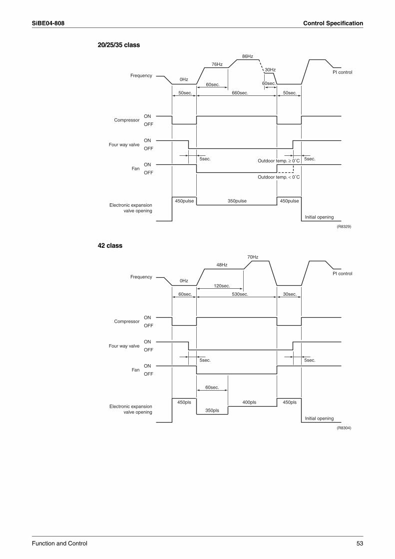
SiBE04-808 Control Specification
20/25/35 class
42 class
Frequency
Compressor
Four way valve
Fan
Electronic expansionvalve opening
ON
OFF
ON
OFF
ON
OFF
0Hz
5sec.
350pulse 450pulse450pulse
Initial opening
PI control
5sec.
50sec.50sec. 660sec.
60sec.
76Hz
86Hz
30Hz
(R8329)
60sec.
Outdoor temp. < 0˚C
Outdoor temp. ≥ 0˚C
Frequency
Compressor
Four way valve
Fan
Electronic expansionvalve opening
ON
OFF
ON
OFF
ON
OFF
0Hz
5sec.
400pls
350pls
450pls450pls
Initial opening
PI control
5sec.
30sec.60sec. 530sec.
120sec.
48Hz
70Hz
60sec.
(R8304)
Function and Control 53
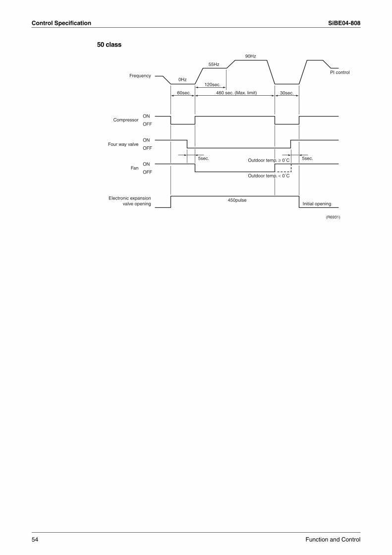
Control Specification SiBE04-808
50 class
Frequency
Compressor
Four way valve
Fan
Electronic expansionvalve opening
ON
OFF
ON
OFF
ON
OFF
0Hz
55Hz
90Hz
5sec.
450pulseInitial opening
PI control
5sec.
30sec.60sec. 460 sec. (Max. limit)
120sec.
(R6931)
Outdoor temp. ≥ 0˚C
Outdoor temp. < 0˚C
54 Function and Control
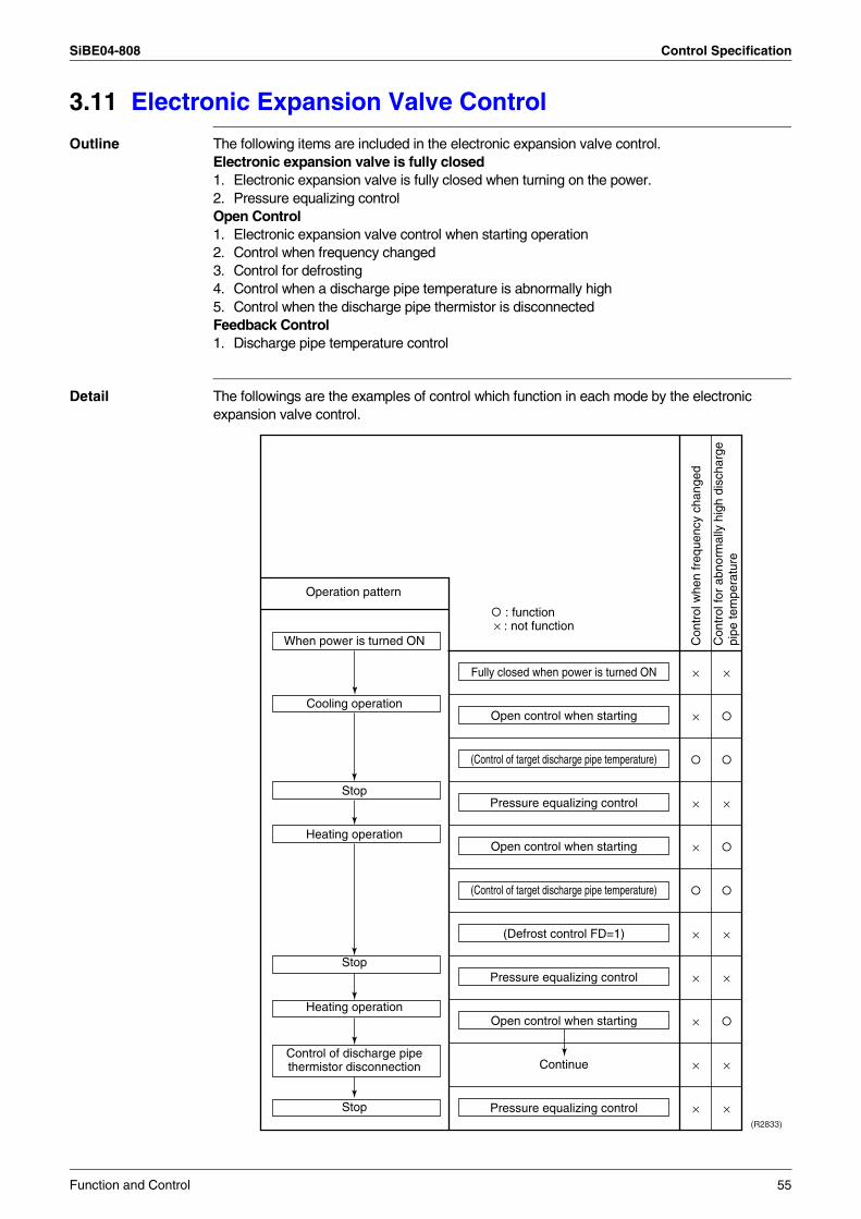
SiBE04-808 Control Specification
3.11 Electronic Expansion Valve Control
Outline The following items are included in the electronic expansion valve control.Electronic expansion valve is fully closed1. Electronic expansion valve is fully closed when turning on the power.2. Pressure equalizing controlOpen Control1. Electronic expansion valve control when starting operation2. Control when frequency changed3. Control for defrosting4. Control when a discharge pipe temperature is abnormally high5. Control when the discharge pipe thermistor is disconnectedFeedback Control1. Discharge pipe temperature control
Detail The followings are the examples of control which function in each mode by the electronic expansion valve control.
(R2833)
×
×
×
×
×
×
×
×
×
×
×
×
×
×
×
Fully closed when power is turned ON
Open control when starting
(Control of target discharge pipe temperature)
Pressure equalizing control
Open control when starting
(Control of target discharge pipe temperature)
(Defrost control FD=1)
Pressure equalizing control
Open control when starting
Continue
Pressure equalizing control
Con
trol
whe
n fr
eque
ncy
chan
ged
Con
trol
for
abno
rmal
ly h
igh
disc
harg
e pi
pe te
mpe
ratu
re
When power is turned ON
Cooling operation
Stop
Heating operation
Stop
Heating operation
Control of discharge pipe thermistor disconnection
Stop
Operation pattern
: function × : not function
Function and Control 55
Control Specification SiBE04-808
3.11.1 Fully Closing with Power ONInitialize the electronic expansion valve when turning on the power, set the opening position and develop pressure equalizing.
3.11.2 Pressure Equalization ControlWhen the compressor is stopped, open and close the electronic expansion valve and develop pressure equalization.
3.11.3 Opening Limit
Outline Limit a maximum and minimum opening of the electronic expansion valve.
Detail Maximum opening : 480 pulses (20/25/35/50 class), 450 pulses (42 class)Minimum opening : 52 pulses (20/25/35 class), 54 pulses (42/50 class)
The electronic expansion valve is fully closed in the room where cooling is stopped and is opened with fixed opening during defrosting.
3.11.4 Starting Operation ControlControl the electronic expansion valve opening when the system is starting, and prevent the system to be super heated or moistened.
3.11.5 High Temperature of the Discharge PipeWhen the compressor is operating, if the discharge pipe temperature exceeds a certain value, open the electronic expansion valve and remove the refrigerant to the low pressure side and lower discharge temperature.
3.11.6 Disconnection of the Discharge Pipe Thermistor
Outline Disconnection of the discharge pipe thermistor is detected by comparing the discharge pipe temperature with the heat exchanger temperature. If any is disconnected, open the electronic expansion valve according to the outdoor air temperature and the operating frequency, and operate for 9 minutes, and then stop.After 3 minutes of waiting, the compressor restarts and the same process is carried out again. If the disconnection is detected 5 times (20/25/35 class) or 4 times (42/50 class) in succession, then the system will be down.When the compressor runs for 60 minutes without any error, the error counter will reset itself.
Detail Detect DisconnectionWhen the timer for open control (20/25/35 class : 810 sec., 42/50 class : 630 sec.) is over, and the 9-minute timer for the compressor operation continuation is not counting time, the following adjustment must be made.1. When the operation mode is cooling
When the following condition is fulfilled, the discharge pipe thermistor disconnection is ascertained.Discharge pipe temperature +6°C < outdoor heat exchanger temperature
2. When the operation mode is heatingWhen the following condition is fulfilled, the discharge pipe thermistor disconnection is ascertained.Discharge pipe temperature +6°C < indoor heat exchanger temperature
56 Function and Control
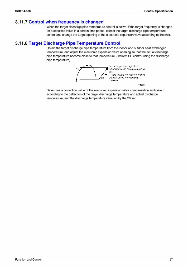
SiBE04-808 Control Specification
3.11.7 Control when frequency is changedWhen the target discharge pipe temperature control is active, if the target frequency is changed for a specified value in a certain time period, cancel the target discharge pipe temperature control and change the target opening of the electronic expansion valve according to the shift.
3.11.8 Target Discharge Pipe Temperature ControlObtain the target discharge pipe temperature from the indoor and outdoor heat exchanger temperature, and adjust the electronic expansion valve opening so that the actual discharge pipe temperature become close to that temperature. (Indirect SH control using the discharge pipe temperature)
Determine a correction value of the electronic expansion valve compensation and drive it according to the deflection of the target discharge temperature and actual discharge temperature, and the discharge temperature variation by the 20 sec.
Function and Control 57
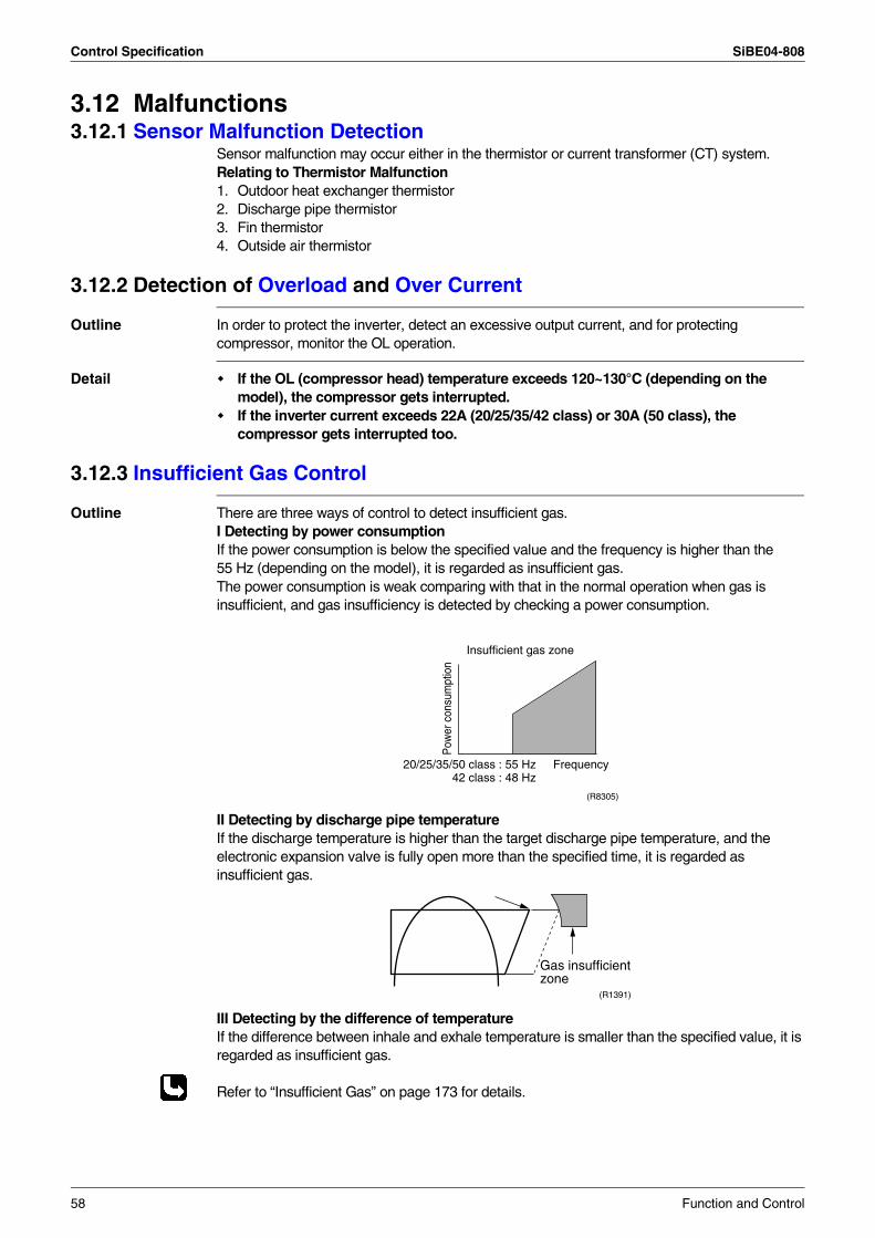
Control Specification SiBE04-808
3.12 Malfunctions3.12.1 Sensor Malfunction Detection
Sensor malfunction may occur either in the thermistor or current transformer (CT) system.Relating to Thermistor Malfunction1. Outdoor heat exchanger thermistor2. Discharge pipe thermistor3. Fin thermistor4. Outside air thermistor
3.12.2 Detection of Overload and Over Current
Outline In order to protect the inverter, detect an excessive output current, and for protecting compressor, monitor the OL operation.
Detail If the OL (compressor head) temperature exceeds 120~130°C (depending on the model), the compressor gets interrupted.If the inverter current exceeds 22A (20/25/35/42 class) or 30A (50 class), the compressor gets interrupted too.
3.12.3 Insufficient Gas Control
Outline There are three ways of control to detect insufficient gas.I Detecting by power consumptionIf the power consumption is below the specified value and the frequency is higher than the 55 Hz (depending on the model), it is regarded as insufficient gas.The power consumption is weak comparing with that in the normal operation when gas is insufficient, and gas insufficiency is detected by checking a power consumption.
II Detecting by discharge pipe temperatureIf the discharge temperature is higher than the target discharge pipe temperature, and the electronic expansion valve is fully open more than the specified time, it is regarded as insufficient gas.
III Detecting by the difference of temperatureIf the difference between inhale and exhale temperature is smaller than the specified value, it is regarded as insufficient gas.
Refer to “Insufficient Gas” on page 173 for details.
Frequency
Pow
er c
onsu
mpt
ion
Insufficient gas zone
20/25/35/50 class : 55 Hz42 class : 48 Hz
(R8305)
Gas insufficientzone
(R1391)
58 Function and Control
SiBE04-808 Control Specification
3.13 Forced Operation Mode
Outline Forced operating mode includes only forced cooling.
Detail Forced Cooling
Item Forced Cooling
Forced operation allowing conditions
1) The outdoor unit is not abnormal and not in the 3-minute stand-by mode.
2) The operating mode of the outdoor unit is the stop mode.
3) The forced operation is ON. The forced operation is allowed when the above “and” conditions are met.
Starting/adjustment If the forced operation switch is pressed as the above conditions are met.
1) Command frequency
20/25/35 class : 68Hz42 class : 47Hz50 class : 66Hz
2) Electronic expansion valve opening
It depends on the capacity of the operating indoor unit.
3) Outdoor unit adjustment
Compressor is in operation
4) Indoor unit adjustment
The command of forced operation is transmitted to the indoor unit.
End 1) When the forced operation switch is pressed again.
2) The operation is to end automatically after 15 min.
Others The protect functions are prior to all others in the forced operation.
Function and Control 59
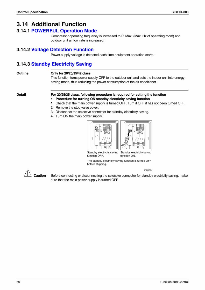
Control Specification SiBE04-808
3.14 Additional Function3.14.1 POWERFUL Operation Mode
Compressor operating frequency is increased to PI Max. (Max. Hz of operating room) and outdoor unit airflow rate is increased.
3.14.2 Voltage Detection Function Power supply voltage is detected each time equipment operation starts.
3.14.3 Standby Electricity Saving
Outline Only for 20/25/35/42 classThis function turns power supply OFF to the outdoor unit and sets the indoor unit into energy-saving mode, thus reducing the power consumption of the air conditioner.
Detail For 20/25/35 class, following procedure is required for setting the functionProcedure for turning ON standby electricity saving function
1. Check that the main power supply is turned OFF. Turn it OFF if has not been turned OFF.2. Remove the stop valve cover.3. Disconnect the selective connector for standby electricity saving.4. Turn ON the main power supply.
Caution Before connecting or disconnecting the selective connector for standby electricity saving, make sure that the main power supply is turned OFF.
Standby electricity saving function OFF.
Standby electricity saving function ON.
The standby electricity saving function is turned OFF before shipping.
(R8328)
1 2 3 1 2 3
60 Function and Control
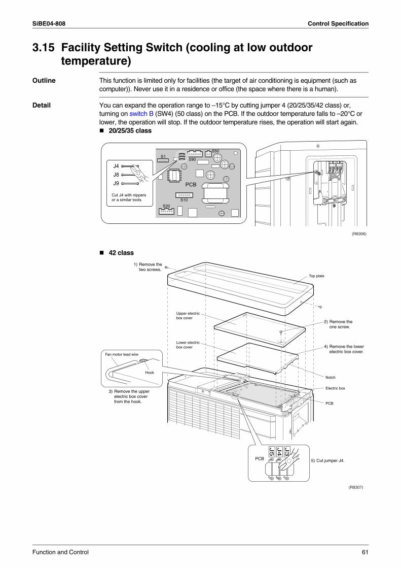
SiBE04-808 Control Specification
3.15 Facility Setting Switch (cooling at low outdoor temperature)
Outline This function is limited only for facilities (the target of air conditioning is equipment (such as computer)). Never use it in a residence or office (the space where there is a human).
Detail You can expand the operation range to –15°C by cutting jumper 4 (20/25/35/42 class) or, turning on switch B (SW4) (50 class) on the PCB. If the outdoor temperature falls to –20°C or lower, the operation will stop. If the outdoor temperature rises, the operation will start again.
20/25/35 class
42 class
(R8306)
1 2 3
S90
PCB
S50
S20S10
S1
J4J8J9
Cut J4 with nippers or a similar tools.
Top plate
Upper electric box cover
Notch
PCB
Lower electric box cover
1) Remove the two screws.
2) Remove the one screw.
4) Remove the lower electric box cover.
3) Remove the upper electric box cover from the hook.
J3
J4
J5
PCB 5) Cut jumper J4.
Hook
Fan motor lead wire
Electric box
(R8307)
Function and Control 61
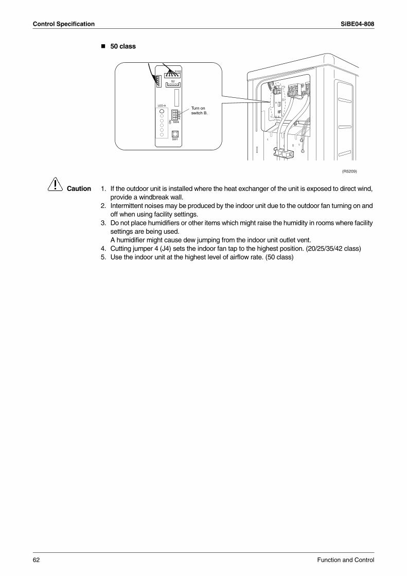
Control Specification SiBE04-808
50 class
Caution 1. If the outdoor unit is installed where the heat exchanger of the unit is exposed to direct wind, provide a windbreak wall.
2. Intermittent noises may be produced by the indoor unit due to the outdoor fan turning on and off when using facility settings.
3. Do not place humidifiers or other items which might raise the humidity in rooms where facility settings are being used.A humidifier might cause dew jumping from the indoor unit outlet vent.
4. Cutting jumper 4 (J4) sets the indoor fan tap to the highest position. (20/25/35/42 class)5. Use the indoor unit at the highest level of airflow rate. (50 class)
LED-A
SW4ON
AB
CD
S102
SW1
S2
Turn on switch B.
(R5209)
62 Function and Control
SiBE04-808
Operation Manual 63
Part 5Operation Manual
1. System Configuration............................................................................642. Instruction..............................................................................................65
2.1 Safety Precautions .................................................................................652.2 FTXS20/25/35/42/50G2V1B...................................................................672.3 ATXS20/25/35/42/50G2V1B ..................................................................96
System Configuration SiBE04-808
1. System ConfigurationAfter the installation and test operation of the room air conditioner have been completed, it should be operated and handled as described below. Every user would like to know the correct method of operation of the room air conditioner, to check if it is capable of cooling (or heating) well, and to know a clever method of using it.In order to meet this expectation of the users, giving sufficient explanations taking enough time can be said to reduce about 80% of the requests for servicing. However good the installation work is and however good the functions are, the customer may blame either the room air conditioner or its installation work because of improper handling. The installation work and handing over of the unit can only be considered to have been completed when its handling has been explained to the user without using technical terms but giving full knowledge of the equipment.
64 Operation Manual
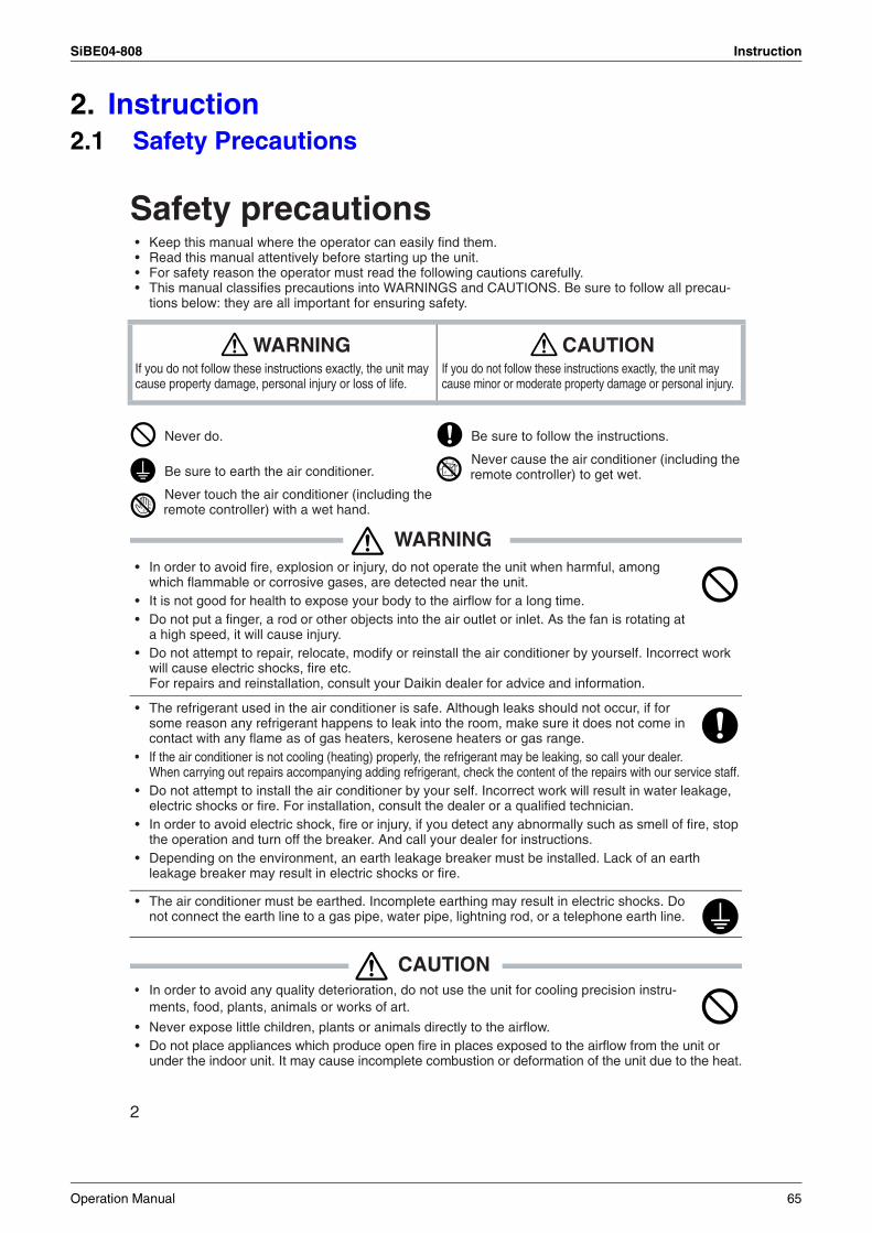
SiBE04-808 Instruction
2. Instruction2.1 Safety Precautions
2
Safety precautions• Keep this manual where the operator can easily find them.• Read this manual attentively before starting up the unit.• For safety reason the operator must read the following cautions carefully.• This manual classifies precautions into WARNINGS and CAUTIONS. Be sure to follow all precau-
tions below: they are all important for ensuring safety.
WARNING• In order to avoid fire, explosion or injury, do not operate the unit when harmful, among
which flammable or corrosive gases, are detected near the unit.• It is not good for health to expose your body to the airflow for a long time.• Do not put a finger, a rod or other objects into the air outlet or inlet. As the fan is rotating at
a high speed, it will cause injury.• Do not attempt to repair, relocate, modify or reinstall the air conditioner by yourself. Incorrect work
will cause electric shocks, fire etc. For repairs and reinstallation, consult your Daikin dealer for advice and information.
• The refrigerant used in the air conditioner is safe. Although leaks should not occur, if for some reason any refrigerant happens to leak into the room, make sure it does not come in contact with any flame as of gas heaters, kerosene heaters or gas range.
• If the air conditioner is not cooling (heating) properly, the refrigerant may be leaking, so call your dealer. When carrying out repairs accompanying adding refrigerant, check the content of the repairs with our service staff.
• Do not attempt to install the air conditioner by your self. Incorrect work will result in water leakage, electric shocks or fire. For installation, consult the dealer or a qualified technician.
• In order to avoid electric shock, fire or injury, if you detect any abnormally such as smell of fire, stop the operation and turn off the breaker. And call your dealer for instructions.
• Depending on the environment, an earth leakage breaker must be installed. Lack of an earth leakage breaker may result in electric shocks or fire.
• The air conditioner must be earthed. Incomplete earthing may result in electric shocks. Do not connect the earth line to a gas pipe, water pipe, lightning rod, or a telephone earth line.
CAUTION• In order to avoid any quality deterioration, do not use the unit for cooling precision instru-
ments, food, plants, animals or works of art.
• Never expose little children, plants or animals directly to the airflow.• Do not place appliances which produce open fire in places exposed to the airflow from the unit or
under the indoor unit. It may cause incomplete combustion or deformation of the unit due to the heat.
WARNINGIf you do not follow these instructions exactly, the unit may cause property damage, personal injury or loss of life.
CAUTIONIf you do not follow these instructions exactly, the unit may cause minor or moderate property damage or personal injury.
Never do. Be sure to follow the instructions.
Be sure to earth the air conditioner.Never cause the air conditioner (including the remote controller) to get wet.
Never touch the air conditioner (including the remote controller) with a wet hand.
Operation Manual 65
Instruction SiBE04-808
3
• Do not block air inlets nor outlets. Impaired airflow may result in insufficient performance or trouble.• Do not stand or sit on the outdoor unit. Do not place any object on the unit to avoid injury, do not
remove the fan guard.• Do not place anything under the indoor or outdoor unit that must be kept away from moisture. In
certain conditions, moisture in the air may condense and drip.• After a long use, check the unit stand and fittings for damage.• Do not touch the air inlet and alminum fins of outdoor unit. It may cause injury.• The appliance is not intended for use by young children or infirm persons without supervision.• Young children should be supervised to ensure that they do not play with the appliance.
• To avoid oxygen deficiency, ventilate the room sufficiently if equipment with burner is used together with the air conditioner.
• Before cleaning, be sure to stop the operation, turn the breaker off or pull out the supply cord.• Do not connect the air conditioner to a power supply different from the one as specified. It
may cause trouble or fire.• Arrange the drain hose to ensure smooth drainage. Incomplete draining may cause wetting of the
building, furniture etc.• Do not place objects in direct proximity of the outdoor unit and do not let leaves and other debris
accumulate around the unit.Leaves are a hotbed for small animals which can enter the unit. Once in the unit, such animals can cause malfunctions, smoke or fire when making contact with electrical parts.
• Do not operate the air conditioner with wet hands.
• Do not wash the indoor unit with excessive water, only use a slightly wet cloth.• Do not place things such as vessels containing water or anything else on top of the unit. Water
may penetrate into the unit and degrade electrical insulations, resulting in an electric shock.
To install the air conditioner in the following types of environments, consult the dealer.• Places with an oily ambient or where steam or soot occurs.• Salty environment such as coastal areas.• Places where sulfide gas occurs such as hot springs.• Places where snow may block the outdoor unit.
The drain from the outdoor unit must be discharged to a place of good drainage.
For installation, choose a place as described below.• A place solid enough to bear the weight of the unit which does not amplify the operation noise or vibration.• A place from where the air discharged from the outdoor unit or the operation noise will not annoy
your neighbours.
• For power supply, be sure to use a separate power circuit dedicated to the air conditioner.
• Relocating the air conditioner requires specialized knowledge and skills. Please consult the dealer if relocation is necessary for moving or remodeling.
Installation site.
Consider nuisance to your neighbours from noises.
Electrical work.
System relocation.
66 Operation Manual
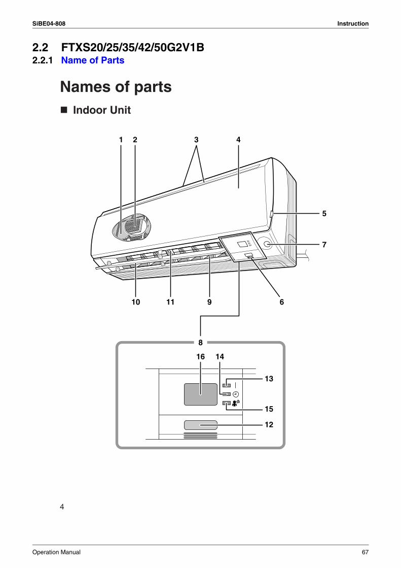
SiBE04-808 Instruction
2.2 FTXS20/25/35/42/50G2V1B2.2.1 Name of Parts
4
Names of partsIndoor Unit
16 14
13
15
12
1 3 4
5
7
91110
8
6
2
Operation Manual 67
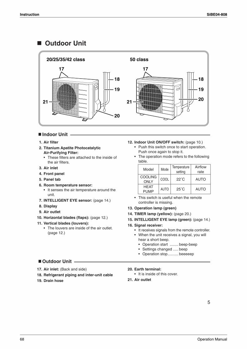
Instruction SiBE04-808
5
Outdoor Unit
Indoor Unit
1. Air filter
2. Titanium Apatite Photocatalytic Air-Purifying Filter:• These filters are attached to the inside of
the air filters.
3. Air inlet
4. Front panel
5. Panel tab
6. Room temperature sensor:• It senses the air temperature around the
unit.
7. INTELLIGENT EYE sensor: (page 14.)
8. Display
9. Air outlet
10. Horizontal blades (flaps): (page 12.)
11. Vertical blades (louvers):• The louvers are inside of the air outlet.
(page 12.)
12. Indoor Unit ON/OFF switch: (page 10.)• Push this switch once to start operation.
Push once again to stop it.• The operation mode refers to the following
table.
• This switch is useful when the remote controller is missing.
13. Operation lamp (green)
14. TIMER lamp (yellow): (page 20.)
15. INTELLIGENT EYE lamp (green): (page 14.)
16. Signal receiver:• It receives signals from the remote controller.• When the unit receives a signal, you will
hear a short beep.• Operation start ........ beep-beep• Settings changed ..... beep• Operation stop.......... beeeeep
Outdoor Unit
17. Air inlet: (Back and side)
18. Refrigerant piping and inter-unit cable
19. Drain hose
20. Earth terminal:• It is inside of this cover.
21. Air outlet
20/25/35/42 class 50 class
18
19
2021
17
18
19
20
21
17
Model ModeTemperature
settingAirflow
rateCOOLING
ONLYCOOL 22˚C AUTO
HEAT PUMP
AUTO 25˚C AUTO
68 Operation Manual
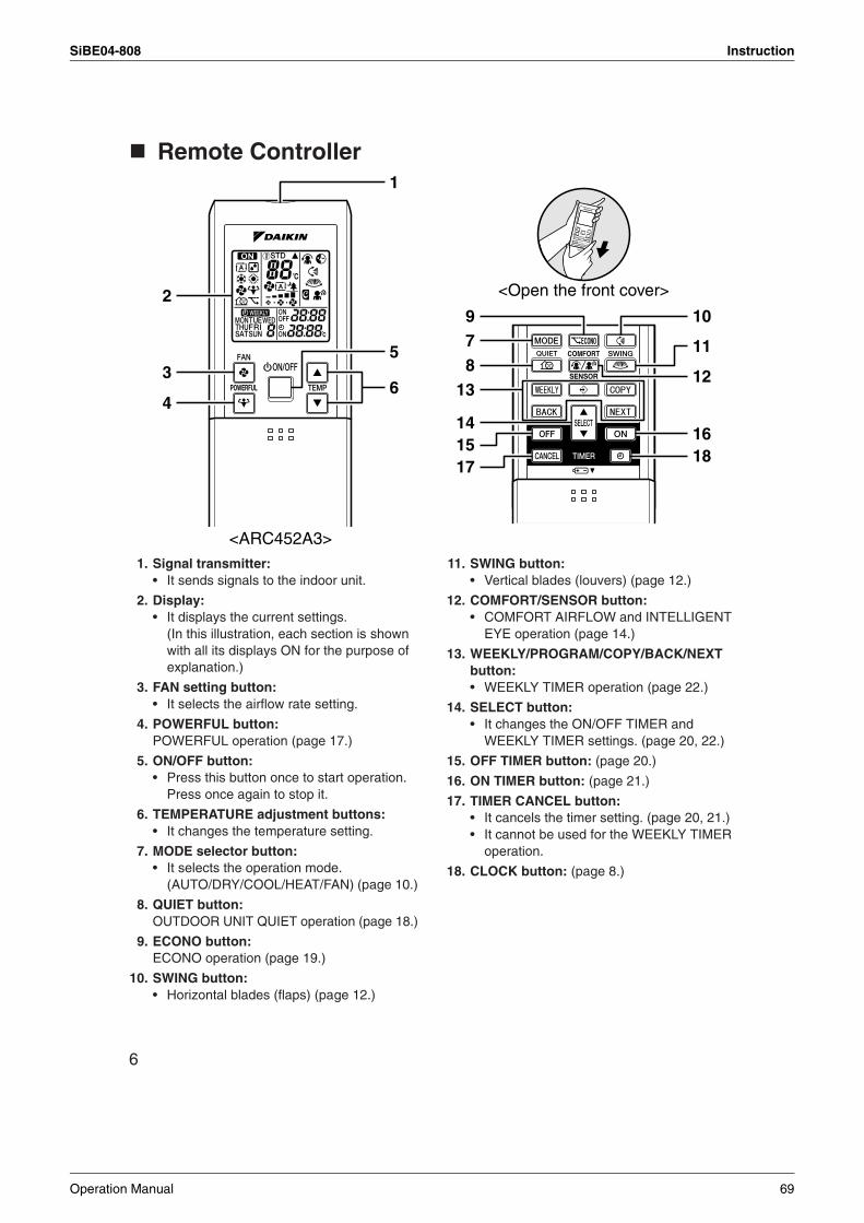
SiBE04-808 Instruction
6
Remote Controller
1. Signal transmitter:• It sends signals to the indoor unit.
2. Display:• It displays the current settings.
(In this illustration, each section is shown with all its displays ON for the purpose of explanation.)
3. FAN setting button: • It selects the airflow rate setting.
4. POWERFUL button: POWERFUL operation (page 17.)
5. ON/OFF button:• Press this button once to start operation.
Press once again to stop it.
6. TEMPERATURE adjustment buttons:• It changes the temperature setting.
7. MODE selector button:• It selects the operation mode.
(AUTO/DRY/COOL/HEAT/FAN) (page 10.)
8. QUIET button: OUTDOOR UNIT QUIET operation (page 18.)
9. ECONO button: ECONO operation (page 19.)
10. SWING button:• Horizontal blades (flaps) (page 12.)
11. SWING button:• Vertical blades (louvers) (page 12.)
12. COMFORT/SENSOR button: • COMFORT AIRFLOW and INTELLIGENT
EYE operation (page 14.)
13. WEEKLY/PROGRAM/COPY/BACK/NEXT button: • WEEKLY TIMER operation (page 22.)
14. SELECT button: • It changes the ON/OFF TIMER and
WEEKLY TIMER settings. (page 20, 22.)
15. OFF TIMER button: (page 20.)
16. ON TIMER button: (page 21.)
17. TIMER CANCEL button:• It cancels the timer setting. (page 20, 21.)• It cannot be used for the WEEKLY TIMER
operation.
18. CLOCK button: (page 8.)
1
5
6
2
3
4
<ARC452A3>
78
13
141517
<Open the front cover>
109
11
12
1618
Operation Manual 69
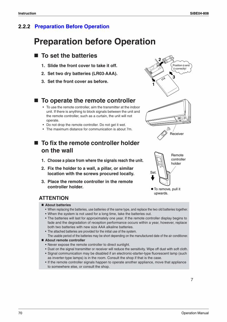
Instruction SiBE04-808
2.2.2 Preparation Before Operation
7
Preparation before Operation
To set the batteries
1. Slide the front cover to take it off.
2. Set two dry batteries (LR03·AAA).
3. Set the front cover as before.
To operate the remote controller • To use the remote controller, aim the transmitter at the indoor
unit. If there is anything to block signals between the unit and the remote controller, such as a curtain, the unit will not operate.
• Do not drop the remote controller. Do not get it wet.• The maximum distance for communication is about 7m.
To fix the remote controller holder on the wall
1. Choose a place from where the signals reach the unit.
2. Fix the holder to a wall, a pillar, or similar location with the screws procured locally.
3. Place the remote controller in the remote controller holder.
ATTENTION About batteries• When replacing the batteries, use batteries of the same type, and replace the two old batteries together.• When the system is not used for a long time, take the batteries out.• The batteries will last for approximately one year. If the remote controller display begins to
fade and the degradation of reception performance occurs within a year, however, replace both two batteries with new size AAA alkaline batteries.
• The attached batteries are provided for the initial use of the system.The usable period of the batteries may be short depending on the manufactured date of the air conditioner.
About remote controller• Never expose the remote controller to direct sunlight.• Dust on the signal transmitter or receiver will reduce the sensitivity. Wipe off dust with soft cloth.• Signal communication may be disabled if an electronic-starter-type fluorescent lamp (such
as inverter-type lamps) is in the room. Consult the shop if that is the case.• If the remote controller signals happen to operate another appliance, move that appliance
to somewhere else, or consult the shop.
2
3
1
Position + and – correctly!
Receiver
Remote controller holder
Set.
To remove, pull it upwards.
70 Operation Manual
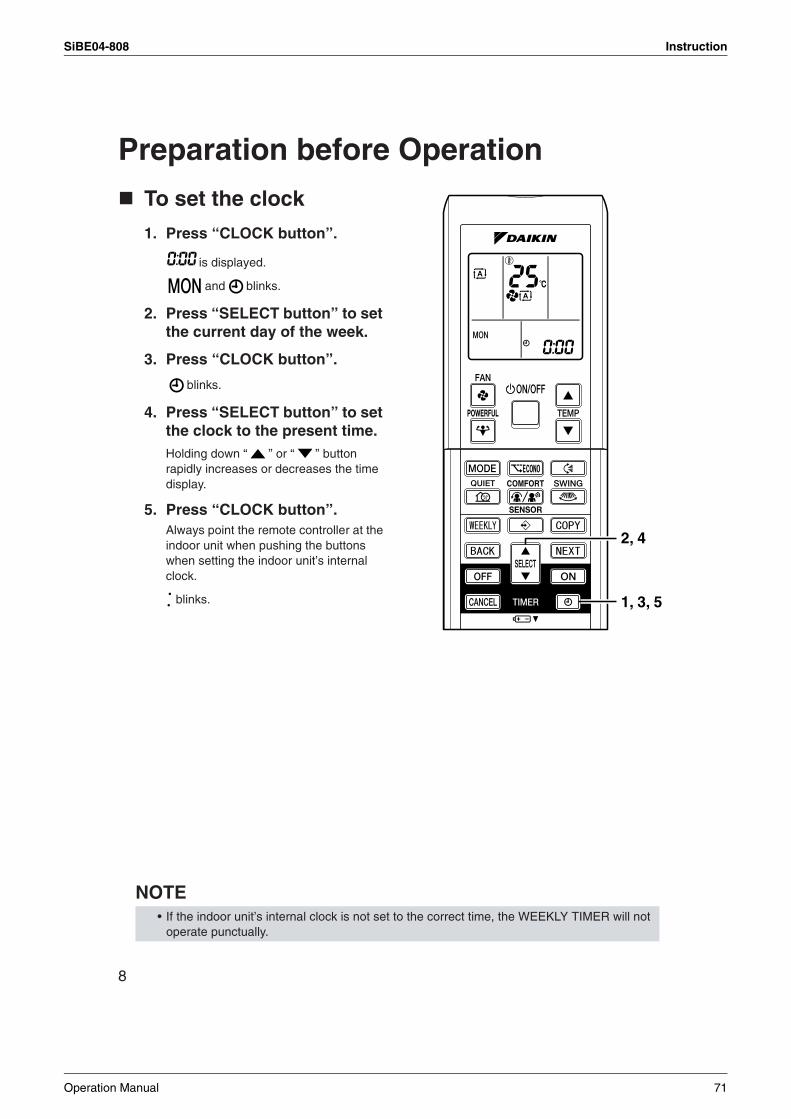
SiBE04-808 Instruction
8
Preparation before Operation
To set the clock
1. Press “CLOCK button”.
is displayed.
and blinks.
2. Press “SELECT button” to set the current day of the week.
3. Press “CLOCK button”.
blinks.
4. Press “SELECT button” to set the clock to the present time.Holding down “ ” or “ ” button rapidly increases or decreases the time display.
5. Press “CLOCK button”.Always point the remote controller at the indoor unit when pushing the buttons when setting the indoor unit’s internal clock.
blinks.
NOTE • If the indoor unit’s internal clock is not set to the correct time, the WEEKLY TIMER will not
operate punctually.
1, 3, 5
2, 4
Operation Manual 71
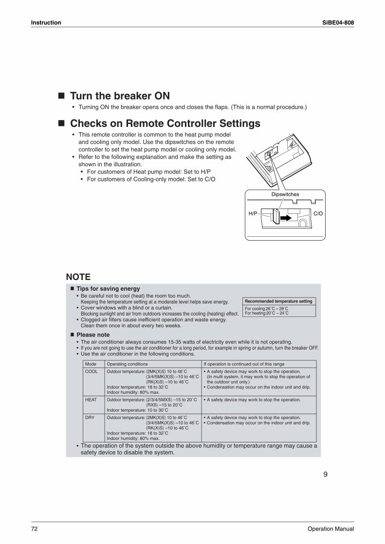
Instruction SiBE04-808
9
Turn the breaker ON• Turning ON the breaker opens once and closes the flaps. (This is a normal procedure.)
Checks on Remote Controller Settings• This remote controller is common to the heat pump model
and cooling only model. Use the dipswitches on the remote controller to set the heat pump model or cooling only model.
• Refer to the following explanation and make the setting as shown in the illustration.• For customers of Heat pump model: Set to H/P• For customers of Cooling-only model: Set to C/O
NOTETips for saving energy• Be careful not to cool (heat) the room too much.
Keeping the temperature setting at a moderate level helps save energy.• Cover windows with a blind or a curtain.
Blocking sunlight and air from outdoors increases the cooling (heating) effect.• Clogged air filters cause inefficient operation and waste energy.
Clean them once in about every two weeks.
Please note• The air conditioner always consumes 15-35 watts of electricity even while it is not operating.• If you are not going to use the air conditioner for a long period, for example in spring or autumn, turn the breaker OFF.• Use the air conditioner in the following conditions.
• The operation of the system outside the above humidity or temperature range may cause a safety device to disable the system.
H/P C/O
Dipswitches
Recommended temperature setting
For cooling:26˚C – 28˚CFor heating:20˚C – 24˚C
Mode Operating conditions If operation is continued out of this range
COOL Outdoor temperature: ⟨2MK(X)S⟩ 10 to 46˚C⟨3/4/5MK(X)S⟩ –10 to 46˚C⟨RK(X)S⟩ –10 to 46˚C
Indoor temperature: 18 to 32˚CIndoor humidity: 80% max.
• A safety device may work to stop the operation.(In multi system, it may work to stop the operation of the outdoor unit only.)
• Condensation may occur on the indoor unit and drip.
HEAT Outdoor temperature: ⟨2/3/4/5MXS⟩ –15 to 20˚C⟨RXS⟩ –15 to 20˚C
Indoor temperature: 10 to 30˚C
• A safety device may work to stop the operation.
DRY Outdoor temperature: ⟨2MK(X)S⟩ 10 to 46˚C⟨3/4/5MK(X)S⟩ –10 to 46˚C⟨RK(X)S⟩ –10 to 46˚C
Indoor temperature: 18 to 32˚CIndoor humidity: 80% max.
• A safety device may work to stop the operation.• Condensation may occur on the indoor unit and drip.
72 Operation Manual
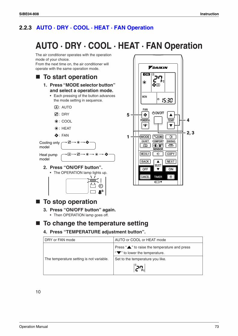
SiBE04-808 Instruction
2.2.3 AUTO · DRY · COOL · HEAT · FAN Operation
10
AUTO · DRY · COOL · HEAT · FAN OperationThe air conditioner operates with the operation mode of your choice. From the next time on, the air conditioner will operate with the same operation mode.
To start operation1. Press “MODE selector button”
and select a operation mode.• Each pressing of the button advances
the mode setting in sequence.
: AUTO
: DRY
: COOL
: HEAT
: FAN
2. Press “ON/OFF button”.• The OPERATION lamp lights up.
To stop operation3. Press “ON/OFF button” again.
• Then OPERATION lamp goes off.
To change the temperature setting4. Press “TEMPERATURE adjustment button”.
DRY or FAN mode AUTO or COOL or HEAT mode
The temperature setting is not variable.
Press “ ” to raise the temperature and press
“ ” to lower the temperature.
Set to the temperature you like.
1
5
2, 3
4
Cooling only model
Heat pump model
Operation Manual 73
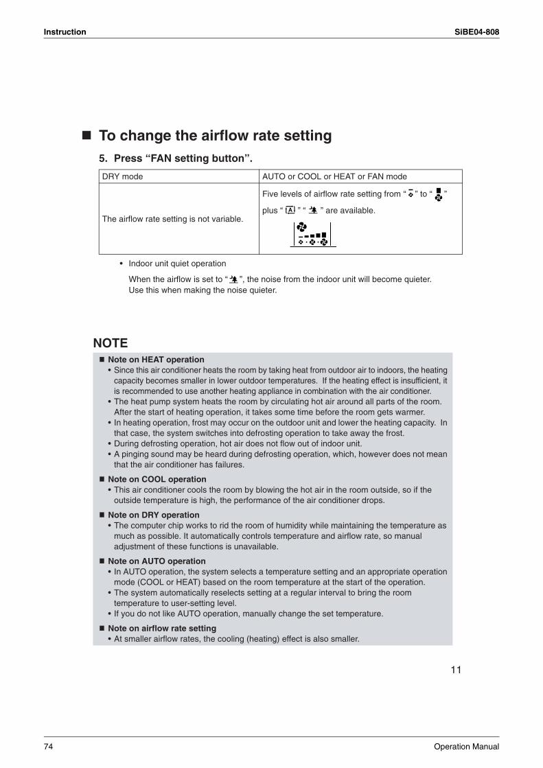
Instruction SiBE04-808
11
To change the airflow rate setting5. Press “FAN setting button”.
• Indoor unit quiet operation
When the airflow is set to “ ”, the noise from the indoor unit will become quieter. Use this when making the noise quieter.
NOTE
DRY mode AUTO or COOL or HEAT or FAN mode
The airflow rate setting is not variable.
Five levels of airflow rate setting from “ ” to “ ”
plus “ ” “ ” are available.
Note on HEAT operation• Since this air conditioner heats the room by taking heat from outdoor air to indoors, the heating
capacity becomes smaller in lower outdoor temperatures. If the heating effect is insufficient, it is recommended to use another heating appliance in combination with the air conditioner.
• The heat pump system heats the room by circulating hot air around all parts of the room. After the start of heating operation, it takes some time before the room gets warmer.
• In heating operation, frost may occur on the outdoor unit and lower the heating capacity. In that case, the system switches into defrosting operation to take away the frost.
• During defrosting operation, hot air does not flow out of indoor unit.• A pinging sound may be heard during defrosting operation, which, however does not mean
that the air conditioner has failures.
Note on COOL operation• This air conditioner cools the room by blowing the hot air in the room outside, so if the
outside temperature is high, the performance of the air conditioner drops.
Note on DRY operation• The computer chip works to rid the room of humidity while maintaining the temperature as
much as possible. It automatically controls temperature and airflow rate, so manual adjustment of these functions is unavailable.
Note on AUTO operation• In AUTO operation, the system selects a temperature setting and an appropriate operation
mode (COOL or HEAT) based on the room temperature at the start of the operation.• The system automatically reselects setting at a regular interval to bring the room
temperature to user-setting level.• If you do not like AUTO operation, manually change the set temperature.
Note on airflow rate setting• At smaller airflow rates, the cooling (heating) effect is also smaller.
74 Operation Manual
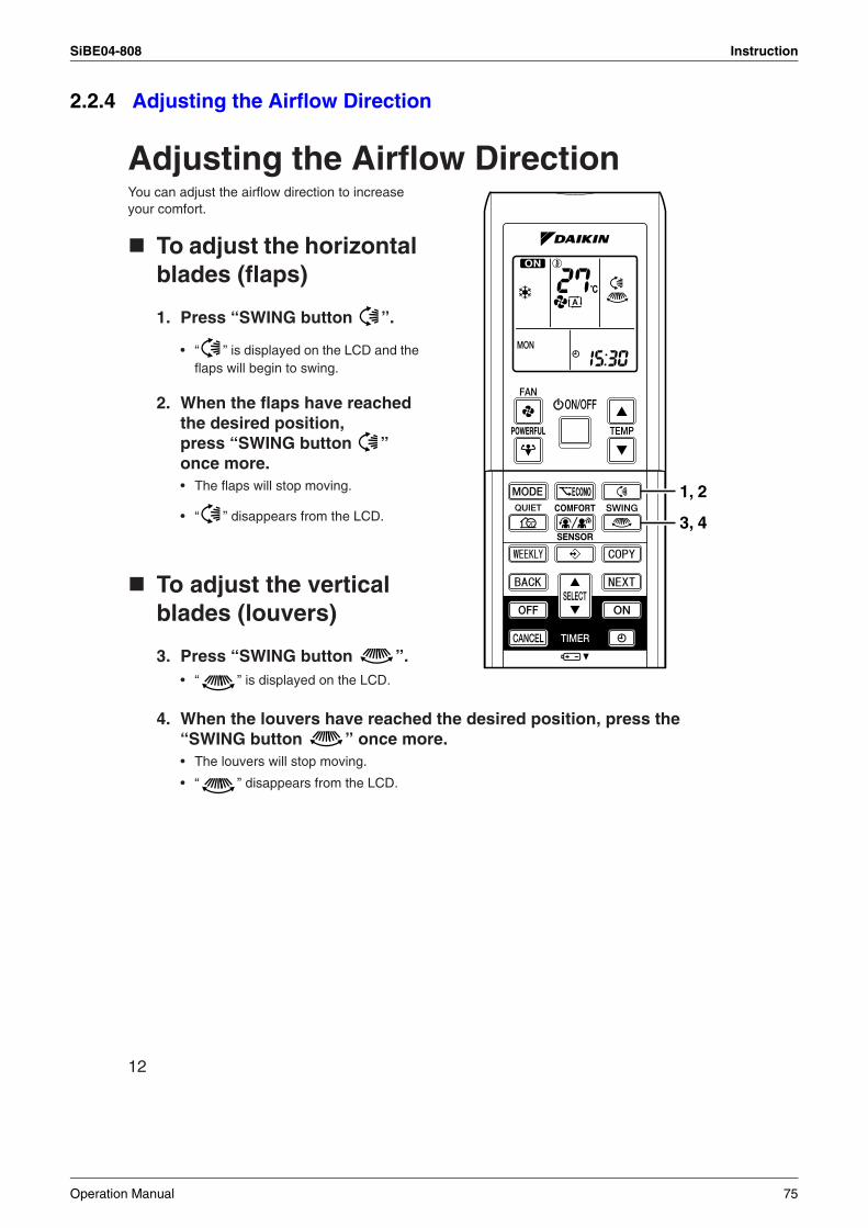
SiBE04-808 Instruction
2.2.4 Adjusting the Airflow Direction
12
Adjusting the Airflow DirectionYou can adjust the airflow direction to increase your comfort.
To adjust the horizontal blades (flaps)
1. Press “SWING button ”.
• “ ” is displayed on the LCD and the flaps will begin to swing.
2. When the flaps have reached the desired position, press “SWING button ” once more.• The flaps will stop moving.
• “ ” disappears from the LCD.
To adjust the vertical blades (louvers)
3. Press “SWING button ”.• “ ” is displayed on the LCD.
4. When the louvers have reached the desired position, press the “SWING button ” once more.• The louvers will stop moving.
• “ ” disappears from the LCD.
1, 2
3, 4
Operation Manual 75
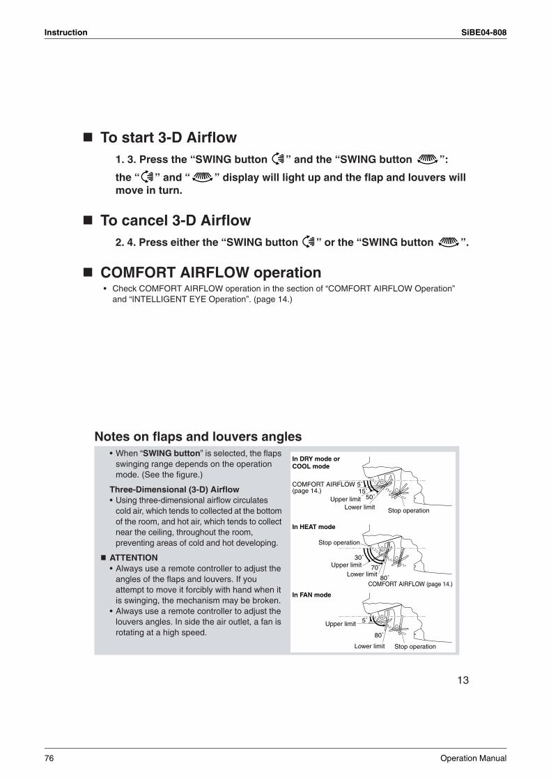
Instruction SiBE04-808
13
To start 3-D Airflow1. 3. Press the “SWING button ” and the “SWING button ”:
the “ ” and “ ” display will light up and the flap and louvers will move in turn.
To cancel 3-D Airflow2. 4. Press either the “SWING button ” or the “SWING button ”.
COMFORT AIRFLOW operation• Check COMFORT AIRFLOW operation in the section of “COMFORT AIRFLOW Operation”
and “INTELLIGENT EYE Operation”. (page 14.)
Notes on flaps and louvers angles • When “SWING button” is selected, the flaps
swinging range depends on the operation mode. (See the figure.)
Three-Dimensional (3-D) Airflow• Using three-dimensional airflow circulates
cold air, which tends to collected at the bottom of the room, and hot air, which tends to collect near the ceiling, throughout the room, preventing areas of cold and hot developing.
ATTENTION• Always use a remote controller to adjust the
angles of the flaps and louvers. If you attempt to move it forcibly with hand when it is swinging, the mechanism may be broken.
• Always use a remote controller to adjust the louvers angles. In side the air outlet, a fan is rotating at a high speed.
5˚
80˚
5˚15˚
50˚
80˚
30˚
70˚
In DRY mode or COOL mode
Upper limit
COMFORT AIRFLOW(page 14.)
COMFORT AIRFLOW (page 14.)
Lower limit
Stop operation
Upper limitLower limit
Upper limit
Lower limit
In HEAT mode
In FAN mode
Stop operation
Stop operation
76 Operation Manual
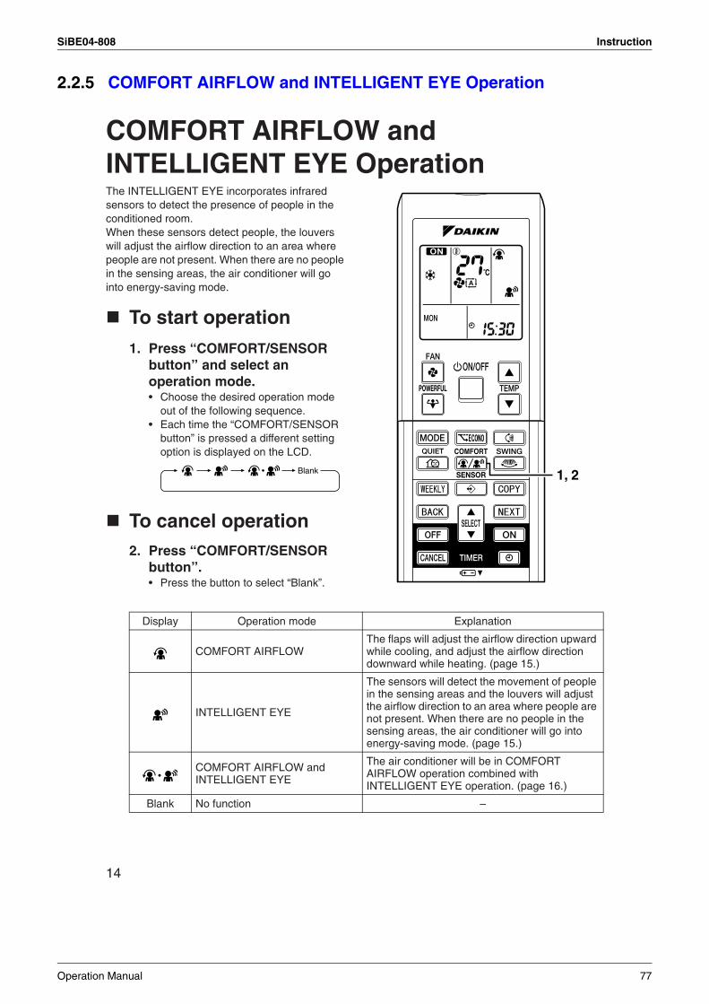
SiBE04-808 Instruction
2.2.5 COMFORT AIRFLOW and INTELLIGENT EYE Operation
14
COMFORT AIRFLOW and INTELLIGENT EYE OperationThe INTELLIGENT EYE incorporates infrared sensors to detect the presence of people in the conditioned room. When these sensors detect people, the louvers will adjust the airflow direction to an area where people are not present. When there are no people in the sensing areas, the air conditioner will go into energy-saving mode.
To start operation
1. Press “COMFORT/SENSOR button” and select an operation mode.• Choose the desired operation mode
out of the following sequence.• Each time the “COMFORT/SENSOR
button” is pressed a different setting option is displayed on the LCD.
To cancel operation2. Press “COMFORT/SENSOR
button”.• Press the button to select “Blank”.
Display Operation mode Explanation
COMFORT AIRFLOWThe flaps will adjust the airflow direction upward while cooling, and adjust the airflow direction downward while heating. (page 15.)
INTELLIGENT EYE
The sensors will detect the movement of people in the sensing areas and the louvers will adjust the airflow direction to an area where people are not present. When there are no people in the sensing areas, the air conditioner will go into energy-saving mode. (page 15.)
COMFORT AIRFLOW and INTELLIGENT EYE
The air conditioner will be in COMFORT AIRFLOW operation combined with INTELLIGENT EYE operation. (page 16.)
Blank No function –
1, 2Blank
Operation Manual 77
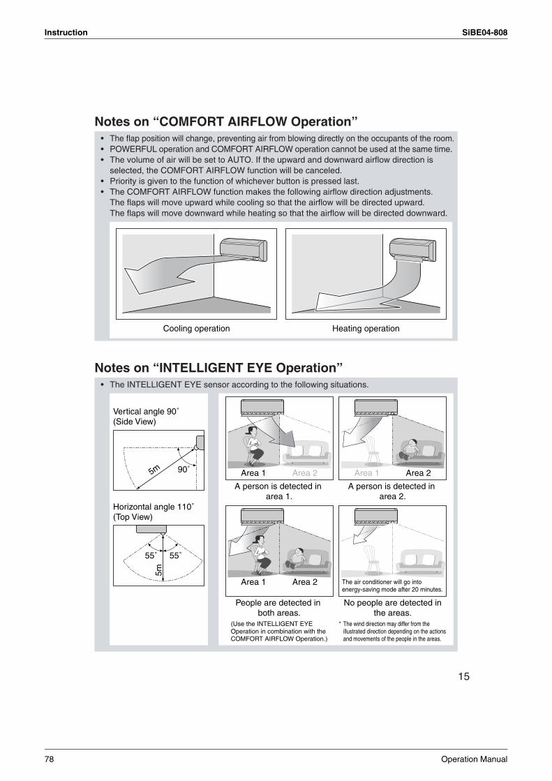
Instruction SiBE04-808
15
Notes on “COMFORT AIRFLOW Operation”
Notes on “INTELLIGENT EYE Operation”
• The flap position will change, preventing air from blowing directly on the occupants of the room.• POWERFUL operation and COMFORT AIRFLOW operation cannot be used at the same time. • The volume of air will be set to AUTO. If the upward and downward airflow direction is
selected, the COMFORT AIRFLOW function will be canceled.• Priority is given to the function of whichever button is pressed last. • The COMFORT AIRFLOW function makes the following airflow direction adjustments.
The flaps will move upward while cooling so that the airflow will be directed upward. The flaps will move downward while heating so that the airflow will be directed downward.
• The INTELLIGENT EYE sensor according to the following situations.
Cooling operation Heating operation
90˚
55˚ 55˚
Horizontal angle 110˚(Top View)
Vertical angle 90˚(Side View)
5m
5m
A person is detected in area 1.
A person is detected in area 2.
No people are detected in the areas.
People are detected in both areas.
* The wind direction may differ from the illustrated direction depending on the actions and movements of the people in the areas.
(Use the INTELLIGENT EYE Operation in combination with the COMFORT AIRFLOW Operation.)
The air conditioner will go into energy-saving mode after 20 minutes.
Area 1 Area 2
Area 1 Area 2
Area 1 Area 2
78 Operation Manual
SiBE04-808 Instruction
16
COMFORT AIRFLOW and INTELLIGENT EYE Operation
Notes on “INTELLIGENT EYE Operation”
“INTELLIGENT EYE” is useful for Energy Saving
To combine “COMFORT AIRFLOW Operation” and “INTELLIGENT EYE Operation”
CAUTION
• While the air conditioner is in INTELLIGENT EYE operation, the louvers will adjust the airflow direction if there are people in the sensing areas of the INTELLIGENT EYE so that the leftward or rightward airflow will not be directed to the people. If no people are detected in either area 1 or 2 in 20 minutes, the air conditioner will go into energy-saving mode with the set temperature shifted by 2˚C. The air conditioner may go into energy-saving operation even if there are people in the areas. This may occur depending on the clothes the people are wearing if there are no movements of the people in the areas.
• The airflow direction from the louvers will be leftward if there are people in both areas 1 and 2 or if there is a person right in front of the sensors because the sensors on the both sides will detect the person.
• Due to the position of the sensor, people might be exposed to the airflow of the indoor unit if they are close to the front side of the indoor unit. If there are people close to the front side of the indoor unit or in both areas, it is recommended to use the COMFORT AIRFLOW and INTELLIGENT EYE functions simultaneously. When both of them are in use, the air conditioner will not direct the airflow towards the people.
• Sensor may not detect moving objects further than 5m away. (Check the application range)• Sensor detection sensitivity changes according to indoor unit location, the speed of
passersby, temperature range, etc.• The sensor also mistakenly detects pets, sunlight, fluttering curtains and light reflected off of
mirrors as passersby.• NIGHT SET MODE (page 20.) will not go on during use of INTELLIGENT EYE operation.
Energy saving operation• Change the temperature –2˚C in heating / +2˚C in cooling / +2˚C in dry mode from set temperature.• Decrease the airflow rate slightly in FAN mode only. If no presence detected in the room
during 20 minutes.
• The air conditioner can go into operation with the COMFORT AIRFLOW and INTELLIGENT EYE functions combined. The flaps adjust the airflow direction upward (while in cooling operation) and downward (while in heating operation), during which the sensors of the INTELLIGENT EYE are working to detect the movement of people. When the sensors detect people, the louvers will direct the airflow in such way that it will not be blown directly on them. If there are no people, the air conditioner will go into energy-saving operation after 20 minutes.
• Do not place large objects near the sensor.Also keep heating units or humidifiers outside the sensor’s detection area. This sensor can detect undesirable objects.
• Do not hit or violently push the INTELLIGENT EYE sensor. This can lead to damage and malfunction.
Operation Manual 79
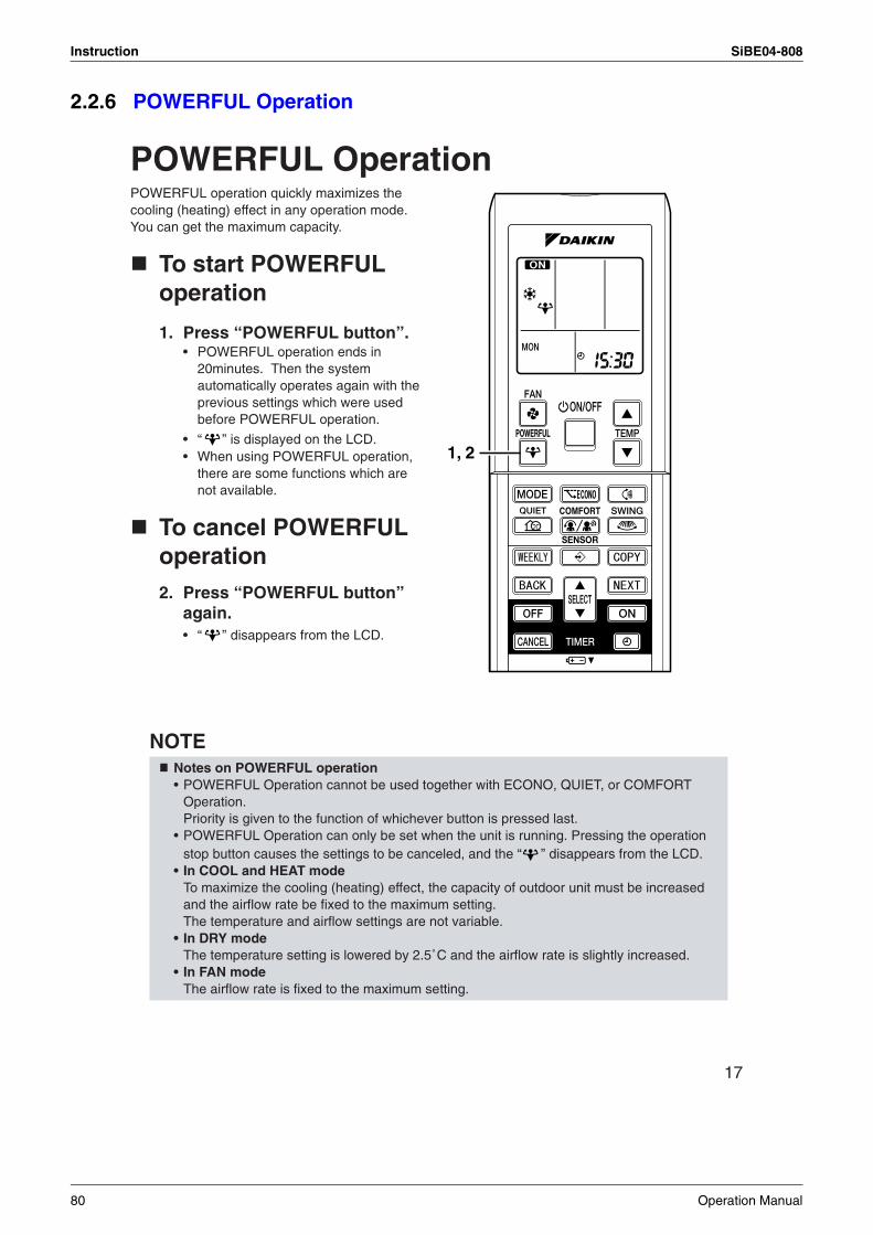
Instruction SiBE04-808
2.2.6 POWERFUL Operation
17
POWERFUL OperationPOWERFUL operation quickly maximizes the cooling (heating) effect in any operation mode. You can get the maximum capacity.
To start POWERFUL operation
1. Press “POWERFUL button”.• POWERFUL operation ends in
20minutes. Then the system automatically operates again with the previous settings which were used before POWERFUL operation.
• “ ” is displayed on the LCD.• When using POWERFUL operation,
there are some functions which are not available.
To cancel POWERFUL operation2. Press “POWERFUL button”
again.• “ ” disappears from the LCD.
NOTE Notes on POWERFUL operation• POWERFUL Operation cannot be used together with ECONO, QUIET, or COMFORT
Operation. Priority is given to the function of whichever button is pressed last.
• POWERFUL Operation can only be set when the unit is running. Pressing the operation stop button causes the settings to be canceled, and the “ ” disappears from the LCD.
• In COOL and HEAT modeTo maximize the cooling (heating) effect, the capacity of outdoor unit must be increased and the airflow rate be fixed to the maximum setting.The temperature and airflow settings are not variable.
• In DRY modeThe temperature setting is lowered by 2.5˚C and the airflow rate is slightly increased.
• In FAN modeThe airflow rate is fixed to the maximum setting.
1, 2
80 Operation Manual
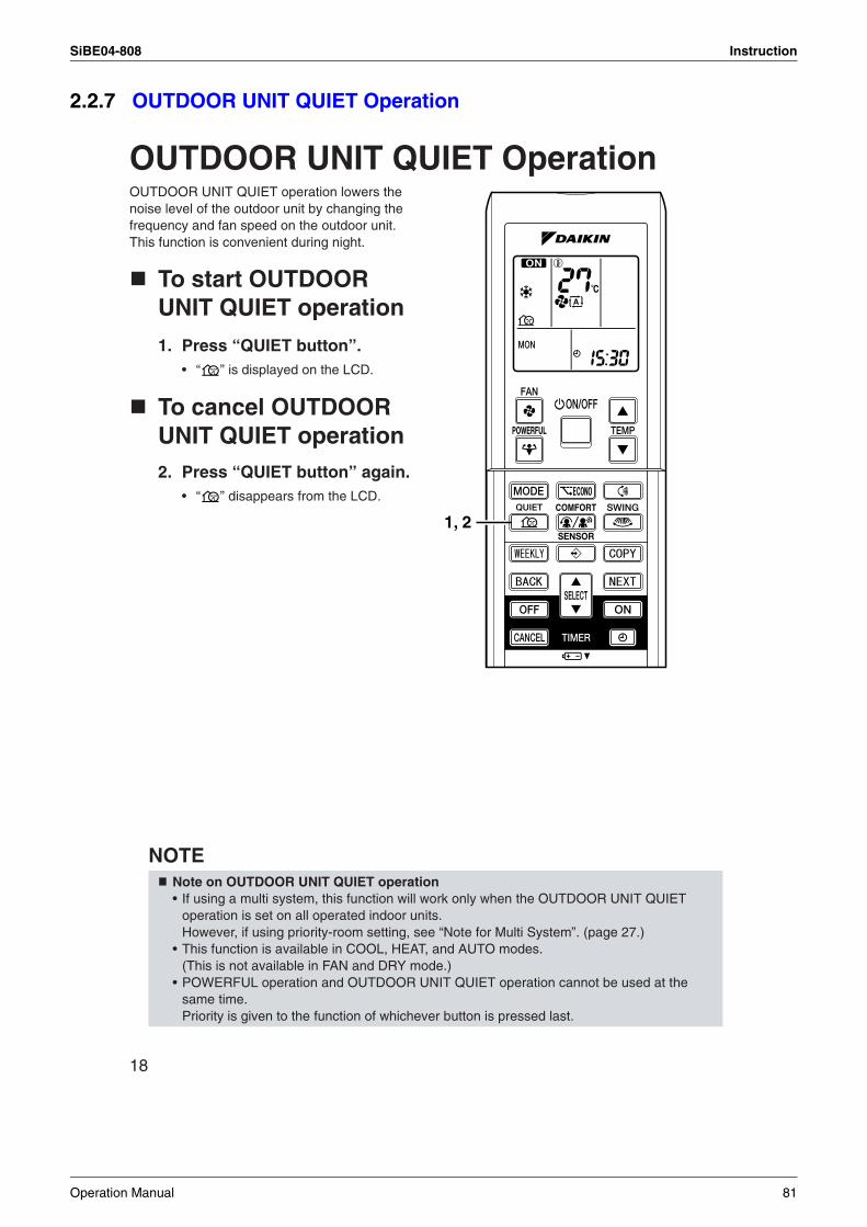
SiBE04-808 Instruction
2.2.7 OUTDOOR UNIT QUIET Operation
18
OUTDOOR UNIT QUIET OperationOUTDOOR UNIT QUIET operation lowers the noise level of the outdoor unit by changing the frequency and fan speed on the outdoor unit. This function is convenient during night.
To start OUTDOOR UNIT QUIET operation
1. Press “QUIET button”.• “ ” is displayed on the LCD.
To cancel OUTDOOR UNIT QUIET operation2. Press “QUIET button” again.
• “ ” disappears from the LCD.
NOTE Note on OUTDOOR UNIT QUIET operation• If using a multi system, this function will work only when the OUTDOOR UNIT QUIET
operation is set on all operated indoor units.However, if using priority-room setting, see “Note for Multi System”. (page 27.)
• This function is available in COOL, HEAT, and AUTO modes.(This is not available in FAN and DRY mode.)
• POWERFUL operation and OUTDOOR UNIT QUIET operation cannot be used at the same time. Priority is given to the function of whichever button is pressed last.
1, 2
Operation Manual 81
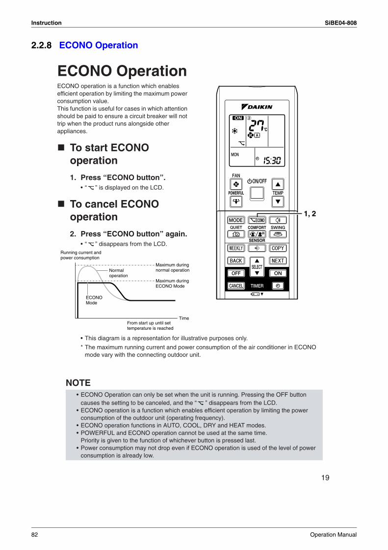
Instruction SiBE04-808
2.2.8 ECONO Operation
19
ECONO OperationECONO operation is a function which enables efficient operation by limiting the maximum power consumption value. This function is useful for cases in which attention should be paid to ensure a circuit breaker will not trip when the product runs alongside other appliances.
To start ECONO operation
1. Press “ECONO button”.• “ ” is displayed on the LCD.
To cancel ECONO operation
2. Press “ECONO button” again.• “ ” disappears from the LCD.
• This diagram is a representation for illustrative purposes only.
* The maximum running current and power consumption of the air conditioner in ECONO mode vary with the connecting outdoor unit.
NOTE • ECONO Operation can only be set when the unit is running. Pressing the OFF button
causes the setting to be canceled, and the “ ” disappears from the LCD.• ECONO operation is a function which enables efficient operation by limiting the power
consumption of the outdoor unit (operating frequency).• ECONO operation functions in AUTO, COOL, DRY and HEAT modes. • POWERFUL and ECONO operation cannot be used at the same time.
Priority is given to the function of whichever button is pressed last. • Power consumption may not drop even if ECONO operation is used of the level of power
consumption is already low.
1, 2
Running current and power consumption
From start up until set temperature is reached
Time
Maximum during normal operation
Maximum during ECONO Mode
Normal operation
ECONO Mode
82 Operation Manual
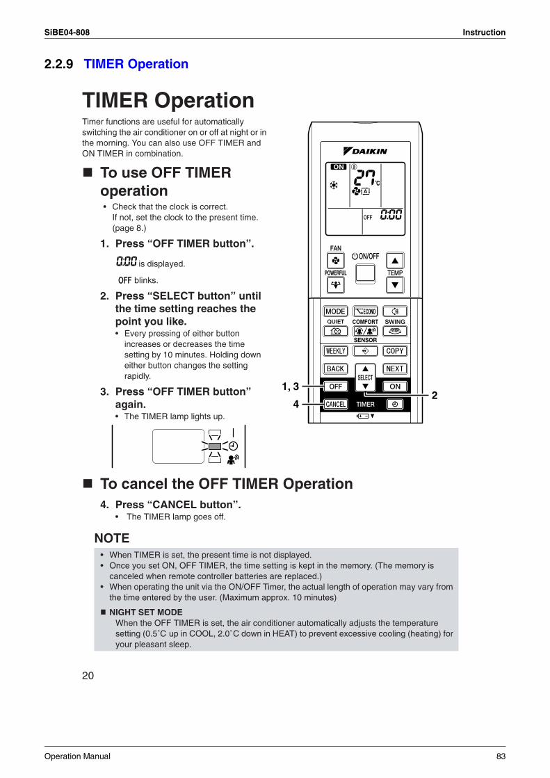
SiBE04-808 Instruction
2.2.9 TIMER Operation
20
TIMER OperationTimer functions are useful for automatically switching the air conditioner on or off at night or in the morning. You can also use OFF TIMER and ON TIMER in combination.
To use OFF TIMER operation• Check that the clock is correct.
If not, set the clock to the present time. (page 8.)
1. Press “OFF TIMER button”.
is displayed.
blinks.
2. Press “SELECT button” until the time setting reaches the point you like.• Every pressing of either button
increases or decreases the time setting by 10 minutes. Holding down either button changes the setting rapidly.
3. Press “OFF TIMER button” again.• The TIMER lamp lights up.
To cancel the OFF TIMER Operation4. Press “CANCEL button”.
• The TIMER lamp goes off.
NOTE • When TIMER is set, the present time is not displayed.• Once you set ON, OFF TIMER, the time setting is kept in the memory. (The memory is
canceled when remote controller batteries are replaced.)• When operating the unit via the ON/OFF Timer, the actual length of operation may vary from
the time entered by the user. (Maximum approx. 10 minutes)
NIGHT SET MODEWhen the OFF TIMER is set, the air conditioner automatically adjusts the temperature setting (0.5˚C up in COOL, 2.0˚C down in HEAT) to prevent excessive cooling (heating) for your pleasant sleep.
1, 3
42
Operation Manual 83
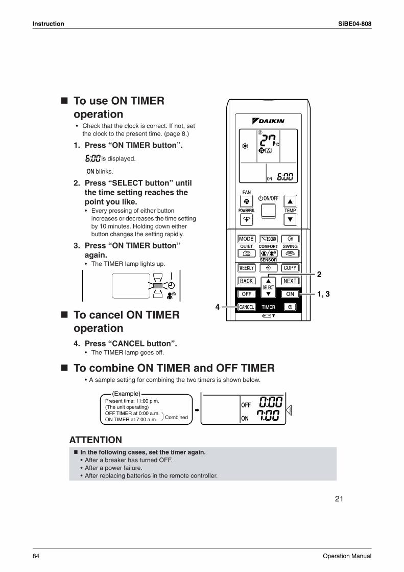
Instruction SiBE04-808
21
To use ON TIMER operation • Check that the clock is correct. If not, set
the clock to the present time. (page 8.)
1. Press “ON TIMER button”.
is displayed.
blinks.
2. Press “SELECT button” until the time setting reaches the point you like.• Every pressing of either button
increases or decreases the time setting by 10 minutes. Holding down either button changes the setting rapidly.
3. Press “ON TIMER button” again.• The TIMER lamp lights up.
To cancel ON TIMER operation4. Press “CANCEL button”.
• The TIMER lamp goes off.
To combine ON TIMER and OFF TIMER• A sample setting for combining the two timers is shown below.
ATTENTION In the following cases, set the timer again.• After a breaker has turned OFF.• After a power failure.• After replacing batteries in the remote controller.
1, 3
4
2
(Example)Present time: 11:00 p.m. (The unit operating)OFF TIMER at 0:00 a.m.ON TIMER at 7:00 a.m. Combined
Dis
play
84 Operation Manual
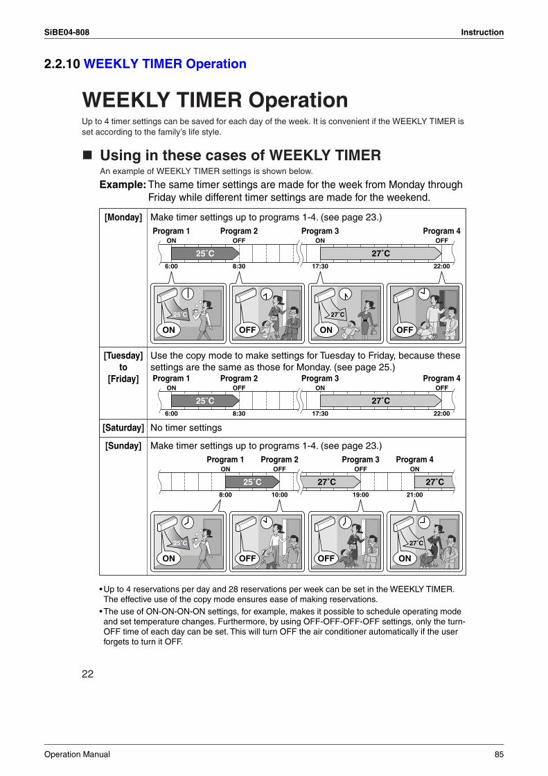
SiBE04-808 Instruction
2.2.10 WEEKLY TIMER Operation
22
WEEKLY TIMER OperationUp to 4 timer settings can be saved for each day of the week. It is convenient if the WEEKLY TIMER is set according to the family’s life style.
Using in these cases of WEEKLY TIMERAn example of WEEKLY TIMER settings is shown below.
6:00 8:30 17:30 22:00
25˚C 27˚C
6:00 8:30 17:30 22:00
25˚C 27˚C
8:00 10:00 19:00 21:00
27˚C 27˚C25˚C
27˚C
27˚C
25˚C
25˚C
Example: The same timer settings are made for the week from Monday through Friday while different timer settings are made for the weekend.
• Up to 4 reservations per day and 28 reservations per week can be set in the WEEKLY TIMER. The effective use of the copy mode ensures ease of making reservations.
• The use of ON-ON-ON-ON settings, for example, makes it possible to schedule operating mode and set temperature changes. Furthermore, by using OFF-OFF-OFF-OFF settings, only the turn-OFF time of each day can be set. This will turn OFF the air conditioner automatically if the user forgets to turn it OFF.
Make timer settings up to programs 1-4. (see page 23.)[Monday]
No timer settings[Saturday]
Make timer settings up to programs 1-4. (see page 23.)[Sunday]
Use the copy mode to make settings for Tuesday to Friday, because these settings are the same as those for Monday. (see page 25.)
[Tuesday]to
[Friday]
Program 1 Program 2 Program 3 Program 4ON OFF ON OFF
Program 1 Program 2 Program 3 Program 4ON OFF ON OFF
ON OFF OFF ONProgram 1 Program 2 Program 3 Program 4
ON
ON
ON
ON
OFFOFF
OFFOFF
Operation Manual 85
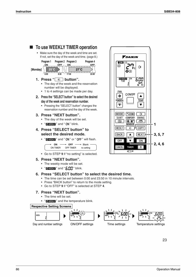
Instruction SiBE04-808
23
To use WEEKLY TIMER operation • Make sure the day of the week and time are set.
If not, set the day of the week and time. (page 8.)
1. Press “ button”. • The day of the week and the reservation
number will be displayed.• 1 to 4 settings can be made per day.
2. Press the “SELECT button” to select the desired day of the week and reservation number.• Pressing the “SELECT button” changes the
reservation number and the day of the week.
3. Press “NEXT button”.• The day of the week will be set.
• “ ” and “ ” blink.
4. Press “SELECT button” to select the desired mode.• “ ” and “ ” or “ ” will flash.
• Go to STEP 9 if “no setting” is selected.
5. Press “NEXT button”.• The weekly mode will be set.
• “ ” and “ ” blink.
6. Press “SELECT button” to select the desired time.• The time can be set between 0:00 and 23:50 in 10 minute intervals. • Press “BACK button” to return to the mode setting.• Go to STEP 9 if “OFF” is selected at STEP 4.
7. Press “NEXT button”. • The time will be set.
• “ ” and the temperature blink.
3, 5, 7
1
2, 4, 6
6:00 8:30 17:30 22:00
25˚C 27˚C
Program 1 Program 2 Program 3 Program 4ON OFF ON OFF
[Monday]
ON OFF BlankON TIMER OFF TIMER no setting
Respective Setting Screens
Day and number settings ON/OFF settings Time settings Temperature settings
86 Operation Manual
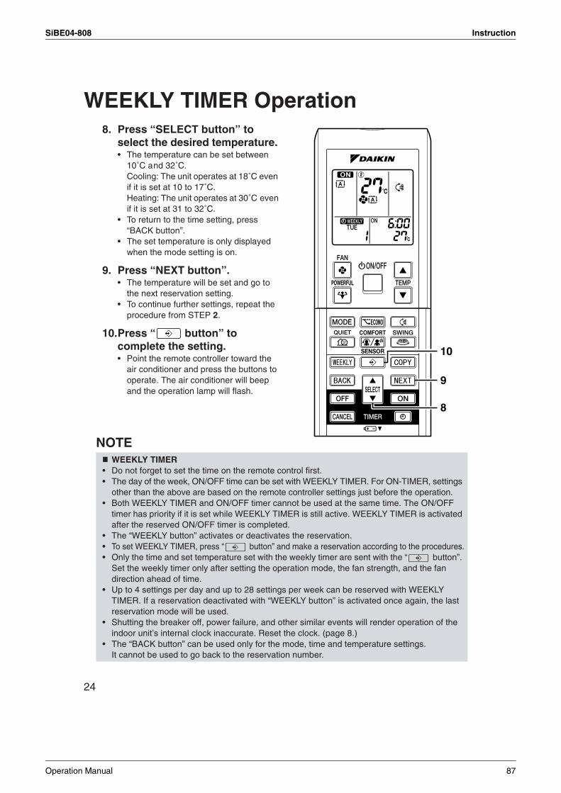
SiBE04-808 Instruction
24
WEEKLY TIMER Operation8. Press “SELECT button” to
select the desired temperature. • The temperature can be set between
10˚C and 32˚C. Cooling: The unit operates at 18˚C even if it is set at 10 to 17˚C. Heating: The unit operates at 30˚C even if it is set at 31 to 32˚C.
• To return to the time setting, press “BACK button”.
• The set temperature is only displayed when the mode setting is on.
9. Press “NEXT button”.• The temperature will be set and go to
the next reservation setting.• To continue further settings, repeat the
procedure from STEP 2.
10.Press “ button” to complete the setting. • Point the remote controller toward the
air conditioner and press the buttons to operate. The air conditioner will beep and the operation lamp will flash.
NOTE WEEKLY TIMER
• Do not forget to set the time on the remote control first.• The day of the week, ON/OFF time can be set with WEEKLY TIMER. For ON-TIMER, settings
other than the above are based on the remote controller settings just before the operation.• Both WEEKLY TIMER and ON/OFF timer cannot be used at the same time. The ON/OFF
timer has priority if it is set while WEEKLY TIMER is still active. WEEKLY TIMER is activated after the reserved ON/OFF timer is completed.
• The “WEEKLY button” activates or deactivates the reservation.• To set WEEKLY TIMER, press “ button” and make a reservation according to the procedures.• Only the time and set temperature set with the weekly timer are sent with the “ button”.
Set the weekly timer only after setting the operation mode, the fan strength, and the fan direction ahead of time.
• Up to 4 settings per day and up to 28 settings per week can be reserved with WEEKLY TIMER. If a reservation deactivated with “WEEKLY button” is activated once again, the last reservation mode will be used.
• Shutting the breaker off, power failure, and other similar events will render operation of the indoor unit’s internal clock inaccurate. Reset the clock. (page 8.)
• The “BACK button” can be used only for the mode, time and temperature settings. It cannot be used to go back to the reservation number.
10
9
8
Operation Manual 87
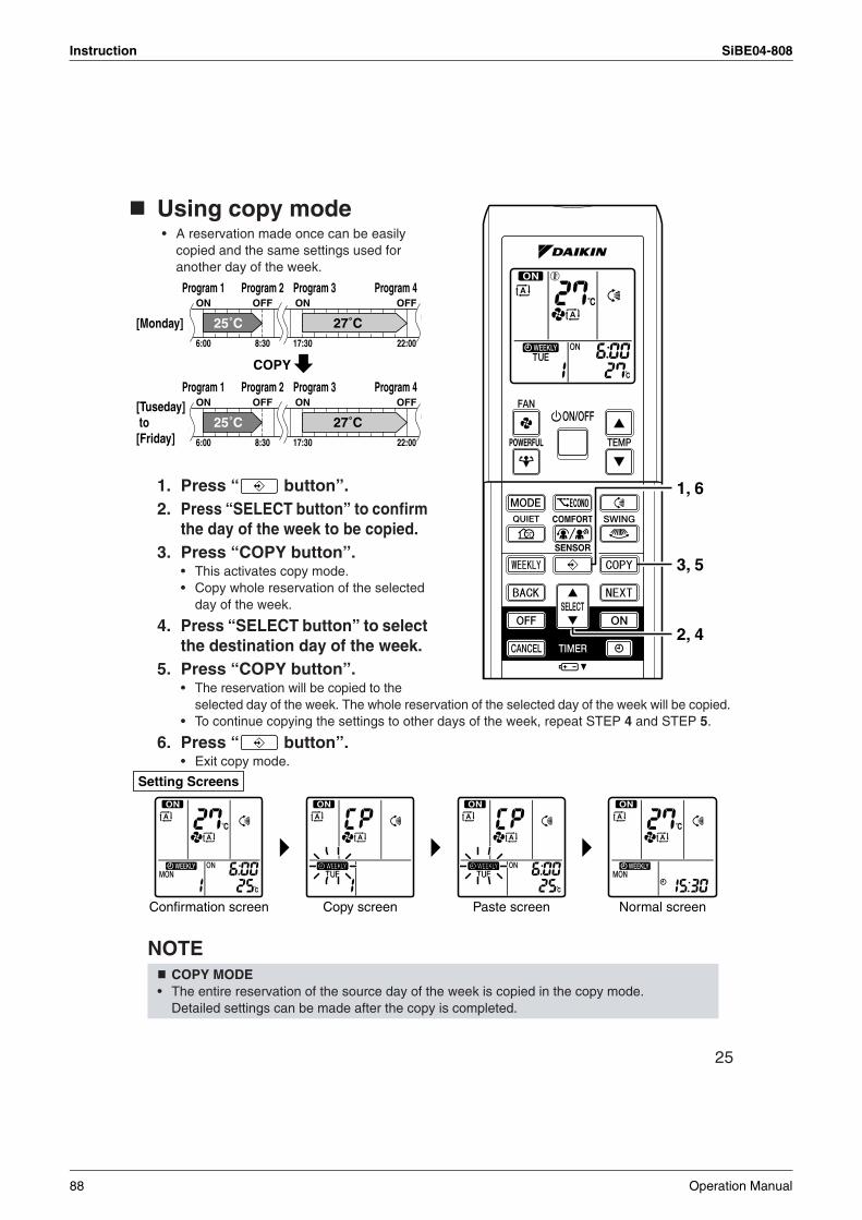
Instruction SiBE04-808
25
Using copy mode • A reservation made once can be easily
copied and the same settings used for another day of the week.
1. Press “ button”.2. Press “SELECT button” to confirm
the day of the week to be copied. 3. Press “COPY button”.
• This activates copy mode. • Copy whole reservation of the selected
day of the week.
4. Press “SELECT button” to select the destination day of the week.
5. Press “COPY button”.• The reservation will be copied to the
selected day of the week. The whole reservation of the selected day of the week will be copied. • To continue copying the settings to other days of the week, repeat STEP 4 and STEP 5.
6. Press “ button”.• Exit copy mode.
NOTE COPY MODE
• The entire reservation of the source day of the week is copied in the copy mode. Detailed settings can be made after the copy is completed.
1, 6
3, 5
2, 4
6:00 8:30 17:30 22:00
25˚C 27˚C
6:00 8:30 17:30 22:00
25˚C 27˚C
Program 1 Program 2 Program 3 Program 4ON OFF ON OFF
[Monday]
COPY
Program 1 Program 2 Program 3 Program 4ON OFF ON OFF[Tuseday]
to [Friday]
Setting Screens
Confirmation screen Copy screen Paste screen Normal screen
88 Operation Manual
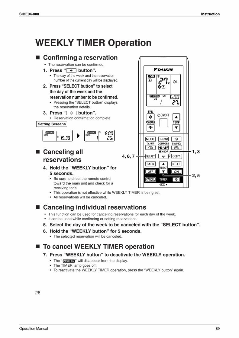
SiBE04-808 Instruction
26
WEEKLY TIMER Operation
Confirming a reservation • The reservation can be confirmed.
1. Press “ button”.• The day of the week and the reservation
number of the current day will be displayed.
2. Press “SELECT button” to select the day of the week and the reservation number to be confirmed. • Pressing the “SELECT button” displays
the reservation details.
3. Press “ button”.• Reservation confirmation complete.
Canceling all reservations4. Hold the “WEEKLY button” for
5 seconds. • Be sure to direct the remote control
toward the main unit and check for a receiving tone.
• This operation is not effective while WEEKLY TIMER is being set.• All reservations will be canceled.
Canceling individual reservations• This function can be used for canceling reservations for each day of the week. • It can be used while confirming or setting reservations.
5. Select the day of the week to be canceled with the “SELECT button”.6. Hold the “WEEKLY button” for 5 seconds.
• The selected reservation will be canceled.
To cancel WEEKLY TIMER operation 7. Press “WEEKLY button” to deactivate the WEEKLY operation.
• The “ ” will disappear from the display.• The TIMER lamp goes off.• To reactivate the WEEKLY TIMER operation, press the “WEEKLY button” again.
1, 3
2, 5
4, 6, 7
Setting Screens
Operation Manual 89
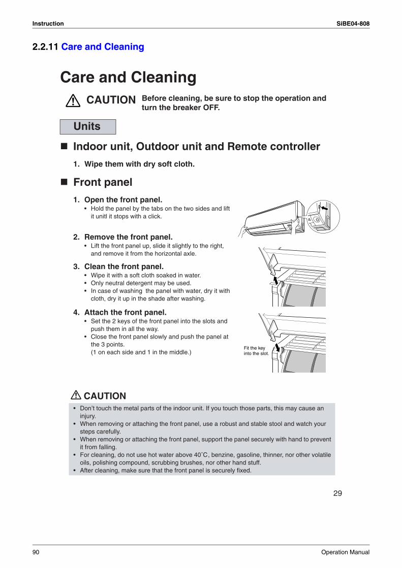
Instruction SiBE04-808
2.2.11 Care and Cleaning
29
Care and CleaningCAUTION
Indoor unit, Outdoor unit and Remote controller
1. Wipe them with dry soft cloth.
Front panel
1. Open the front panel. • Hold the panel by the tabs on the two sides and lift
it unitl it stops with a click.
2. Remove the front panel.• Lift the front panel up, slide it slightly to the right,
and remove it from the horizontal axle.
3. Clean the front panel.• Wipe it with a soft cloth soaked in water.• Only neutral detergent may be used.• In case of washing the panel with water, dry it with
cloth, dry it up in the shade after washing.
4. Attach the front panel. • Set the 2 keys of the front panel into the slots and
push them in all the way.• Close the front panel slowly and push the panel at
the 3 points. (1 on each side and 1 in the middle.)
CAUTION
Units
• Don’t touch the metal parts of the indoor unit. If you touch those parts, this may cause an injury.
• When removing or attaching the front panel, use a robust and stable stool and watch your steps carefully.
• When removing or attaching the front panel, support the panel securely with hand to prevent it from falling.
• For cleaning, do not use hot water above 40˚C, benzine, gasoline, thinner, nor other volatile oils, polishing compound, scrubbing brushes, nor other hand stuff.
• After cleaning, make sure that the front panel is securely fixed.
Before cleaning, be sure to stop the operation and turn the breaker OFF.
Fit the key into the slot.
90 Operation Manual
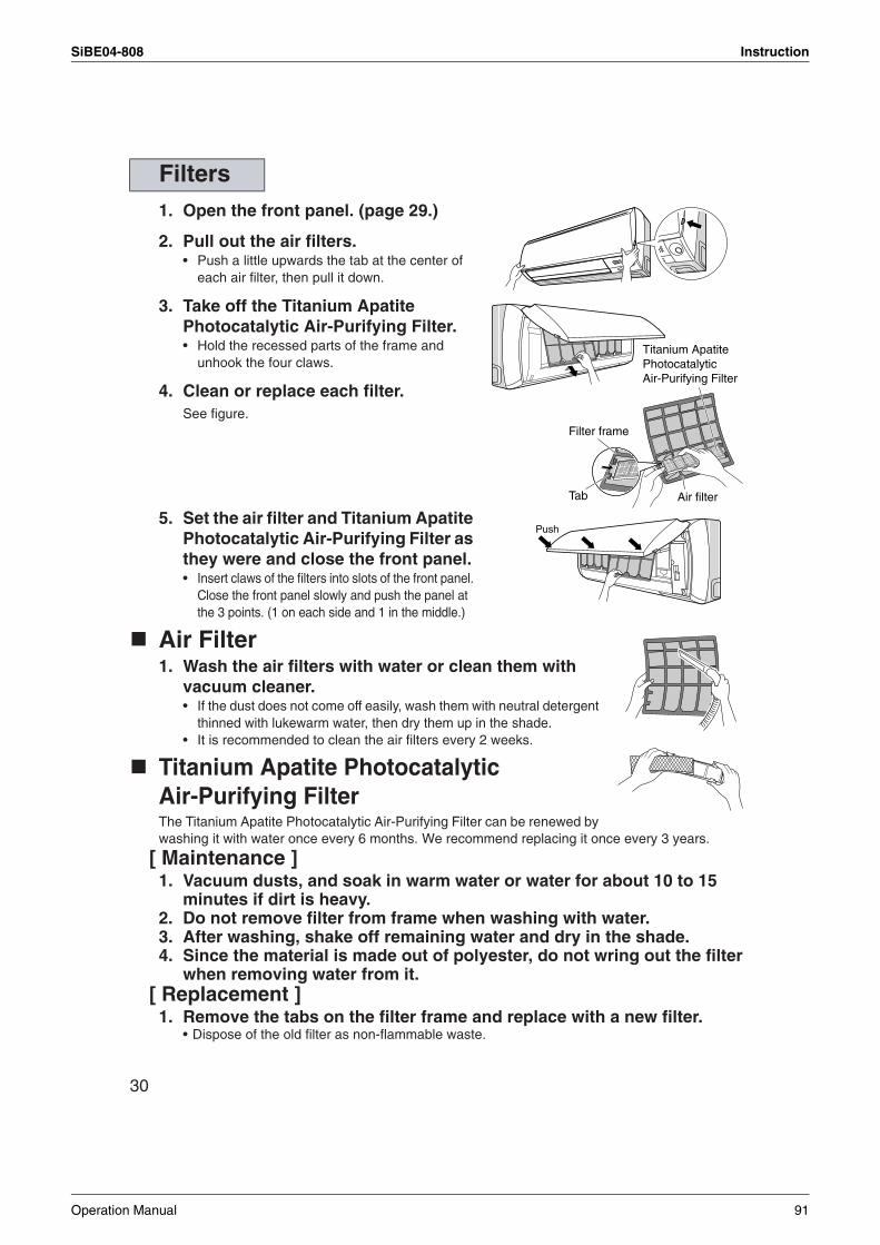
SiBE04-808 Instruction
30
1. Open the front panel. (page 29.)
2. Pull out the air filters. • Push a little upwards the tab at the center of
each air filter, then pull it down.
3. Take off the Titanium Apatite Photocatalytic Air-Purifying Filter. • Hold the recessed parts of the frame and
unhook the four claws.
4. Clean or replace each filter.See figure.
5. Set the air filter and Titanium Apatite Photocatalytic Air-Purifying Filter as they were and close the front panel. • Insert claws of the filters into slots of the front panel.
Close the front panel slowly and push the panel at the 3 points. (1 on each side and 1 in the middle.)
Air Filter 1. Wash the air filters with water or clean them with
vacuum cleaner.• If the dust does not come off easily, wash them with neutral detergent
thinned with lukewarm water, then dry them up in the shade.• It is recommended to clean the air filters every 2 weeks.
Titanium Apatite Photocatalytic Air-Purifying Filter The Titanium Apatite Photocatalytic Air-Purifying Filter can be renewed by washing it with water once every 6 months. We recommend replacing it once every 3 years.
[ Maintenance ]1. Vacuum dusts, and soak in warm water or water for about 10 to 15
minutes if dirt is heavy.2. Do not remove filter from frame when washing with water.3. After washing, shake off remaining water and dry in the shade.4. Since the material is made out of polyester, do not wring out the filter
when removing water from it.[ Replacement ]
1. Remove the tabs on the filter frame and replace with a new filter.• Dispose of the old filter as non-flammable waste.
Filters
Titanium Apatite Photocatalytic Air-Purifying Filter
Filter frame
Air filterTab
Push
Operation Manual 91
Instruction SiBE04-808
31
NOTE
Check
Before a long idle period
1. Operate the “FAN only” for several hours on a fine day to dry out the inside.• Press “MODE” button and select “FAN” operation.
• Press “ON/OFF” button and start operation.
2. After operation stops, turn off the breaker for the room air conditioner.
3. Clean the air filters and set them again.
4. Take out batteries from the remote controller.
• Operation with dirty filters: (1) cannot deodorize the air. (2) cannot clean the air. (3) results in poor heating or cooling. (4) may cause odour.
• To order Titanium Apatite Photocatalytic Air-Purifying Filter contact to the service shop there you bought the air conditioner.
• Dispose of the old filter as non-flammable waste.
Check that the base, stand and other fittings of the outdoor unit are not decayed or corroded.
Check that nothing blocks the air inlets and the outlets of the indoor unit and the outdoor unit.
Check that the drain comes smoothly out of the drain hose during COOL or DRY operation.• If no drain water is seen, water may be leaking from the indoor unit. Stop operation and
consult the service shop if this is the case.
Item Part No.
Titanium Apatite Photocatalytic Air-Purifying Filter (without frame) 1 set KAF970A46
92 Operation Manual
SiBE04-808 Instruction
2.2.12 Troubleshooting
32
Trouble Shooting
The following cases are not air conditioner troubles but have some reasons. You may just continue using it.
These cases are not troubles.
Case ExplanationOperation does not start soon.• When ON/OFF button was pressed
soon after operation was stopped.• When the mode was reselected.
• This is to protect the air conditioner.You should wait for about 3 minutes.
Hot air does not flow out soon after the start of heating operation.
• The air conditioner is warming up. You should wait for 1 to 4 minutes.(The system is designed to start discharging air only after it has reached a certain temperature.)
The heating operation stops suddenly and a flowing sound is heard.
• The system is taking away the frost on the outdoor unit.You should wait for about 4 to 12 minutes.
The outdoor unit emits water or steam.
In HEAT mode• The frost on the outdoor unit melts into water or steam
when the air conditioner is in defrost operation.In COOL or DRY mode• Moisture in the air condenses into water on the cool
surface of outdoor unit piping and drips.
Mist comes out of the indoor unit.
This happens when the air in the room is cooled into mist by the cold airflow during cooling operation.This is because the air in the room is cooled by the heat exchanger and becomes mist during defrost operation.
The indoor unit gives out odour. This happens when smells of the room, furniture, or cigarettes are absorbed into the unit and discharged with the airflow.(If this happens, we recommend you to have the indoor unit washed by a technician. Consult the service shop where you bought the air conditioner.)
The outdoor fan rotates while the air conditioner is not in operation.
After operation is stopped:• The outdoor fan continues rotating for another 60 seconds
for system protection.While the air conditioner is not in operation:• When the outdoor temperature is very high, the outdoor
fan starts rotating for system protection.
The operation stopped suddenly.(OPERATION lamp is on.)
For system protection, the air conditioner may stop operating on a sudden large voltage fluctuation.It automatically resumes operation in about 3 minutes.
No remote controller signals are displayed.The remote controller sensitivity is low.The display is low in contrast or blacked out.The display runs out of control.
• The batteries are dying and the remote controller is malfunc-tioning. Replace all the batteries with new size AAA alkaline batteries. For details, refer to “To set the batteries” of this manual. (page 7.)
* If the reset button is provided, press the reset button after the batteries are replaced.
The ON/OFF TIMER does not operate according to the settings.
• Check if the ON/OFF TIMER and the WEEKLY TIMER are set to the same time. Change or disable the settings in the WEEKLY TIMER. (page 23.)
Operation Manual 93
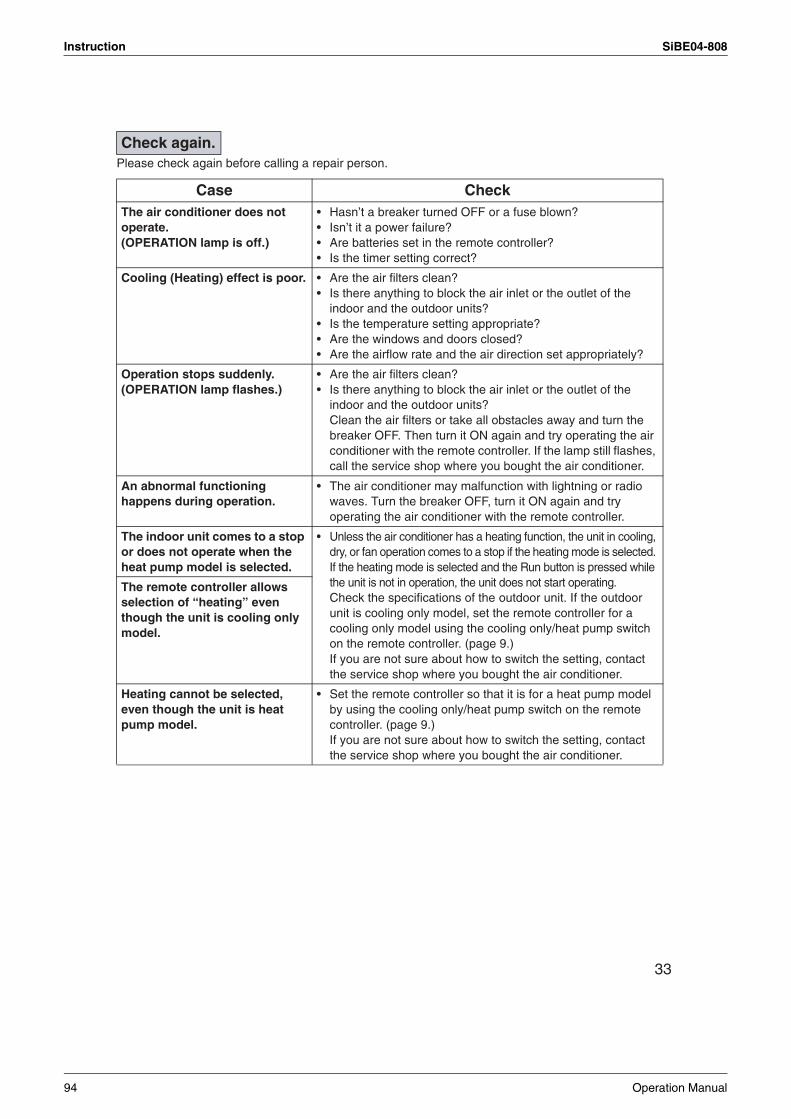
Instruction SiBE04-808
33
Please check again before calling a repair person.
Check again.
Case CheckThe air conditioner does not operate.(OPERATION lamp is off.)
• Hasn’t a breaker turned OFF or a fuse blown?• Isn’t it a power failure?• Are batteries set in the remote controller?• Is the timer setting correct?
Cooling (Heating) effect is poor. • Are the air filters clean?• Is there anything to block the air inlet or the outlet of the
indoor and the outdoor units?• Is the temperature setting appropriate?• Are the windows and doors closed?• Are the airflow rate and the air direction set appropriately?
Operation stops suddenly.(OPERATION lamp flashes.)
• Are the air filters clean?• Is there anything to block the air inlet or the outlet of the
indoor and the outdoor units?Clean the air filters or take all obstacles away and turn the breaker OFF. Then turn it ON again and try operating the air conditioner with the remote controller. If the lamp still flashes, call the service shop where you bought the air conditioner.
An abnormal functioning happens during operation.
• The air conditioner may malfunction with lightning or radio waves. Turn the breaker OFF, turn it ON again and try operating the air conditioner with the remote controller.
The indoor unit comes to a stop or does not operate when the heat pump model is selected.
• Unless the air conditioner has a heating function, the unit in cooling, dry, or fan operation comes to a stop if the heating mode is selected. If the heating mode is selected and the Run button is pressed while the unit is not in operation, the unit does not start operating.Check the specifications of the outdoor unit. If the outdoor unit is cooling only model, set the remote controller for a cooling only model using the cooling only/heat pump switch on the remote controller. (page 9.)If you are not sure about how to switch the setting, contact the service shop where you bought the air conditioner.
The remote controller allows selection of “heating” even though the unit is cooling only model.
Heating cannot be selected, even though the unit is heat pump model.
• Set the remote controller so that it is for a heat pump model by using the cooling only/heat pump switch on the remote controller. (page 9.)If you are not sure about how to switch the setting, contact the service shop where you bought the air conditioner.
94 Operation Manual
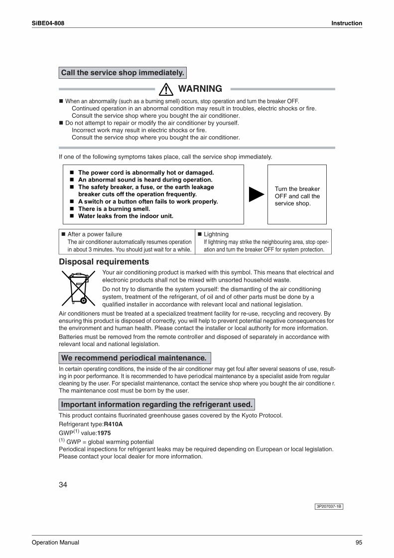
SiBE04-808 Instruction
34
WARNINGWhen an abnormality (such as a burning smell) occurs, stop operation and turn the breaker OFF.
Continued operation in an abnormal condition may result in troubles, electric shocks or fire.Consult the service shop where you bought the air conditioner.
Do not attempt to repair or modify the air conditioner by yourself.Incorrect work may result in electric shocks or fire.Consult the service shop where you bought the air conditioner.
If one of the following symptoms takes place, call the service shop immediately.
Disposal requirementsYour air conditioning product is marked with this symbol. This means that electrical and electronic products shall not be mixed with unsorted household waste.
Do not try to dismantle the system yourself: the dismantling of the air conditioning system, treatment of the refrigerant, of oil and of other parts must be done by a qualified installer in accordance with relevant local and national legislation.
Air conditioners must be treated at a specialized treatment facility for re-use, recycling and recovery. By ensuring this product is disposed of correctly, you will help to prevent potential negative consequences for the environment and human health. Please contact the installer or local authority for more information. Batteries must be removed from the remote controller and disposed of separately in accordance with relevant local and national legislation.
In certain operating conditions, the inside of the air conditioner may get foul after several seasons of use, result-ing in poor performance. It is recommended to have periodical maintenance by a specialist aside from regular cleaning by the user. For specialist maintenance, contact the service shop where you bought the air conditione r.The maintenance cost must be born by the user.
This product contains fluorinated greenhouse gases covered by the Kyoto Protocol.Refrigerant type:R410AGWP(1) value:1975(1) GWP = global warming potentialPeriodical inspections for refrigerant leaks may be required depending on European or local legislation. Please contact your local dealer for more information.
Call the service shop immediately.
After a power failureThe air conditioner automatically resumes operation in about 3 minutes. You should just wait for a while.
LightningIf lightning may strike the neighbouring area, stop oper-ation and turn the breaker OFF for system protection.
We recommend periodical maintenance.
Important information regarding the refrigerant used.
3P207037-1B
Operation Manual 95
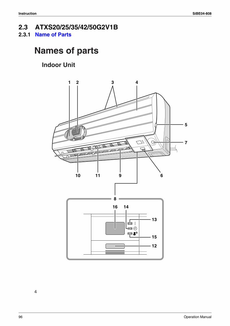
Instruction SiBE04-808
2.3 ATXS20/25/35/42/50G2V1B2.3.1 Name of Parts
4
Names of parts
Indoor Unit
16 14
13
15
12
1 3 4
5
7
91110
8
6
2
96 Operation Manual
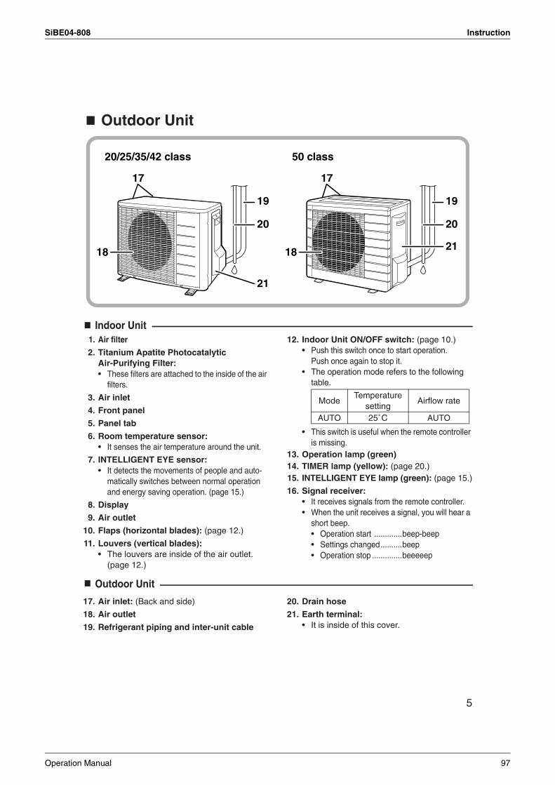
SiBE04-808 Instruction
5
Outdoor Unit
Indoor Unit1. Air filter
2. Titanium Apatite Photocatalytic Air-Purifying Filter:• These filters are attached to the inside of the air
filters.
3. Air inlet
4. Front panel
5. Panel tab
6. Room temperature sensor:• It senses the air temperature around the unit.
7. INTELLIGENT EYE sensor:• It detects the movements of people and auto-
matically switches between normal operation and energy saving operation. (page 15.)
8. Display
9. Air outlet
10. Flaps (horizontal blades): (page 12.)
11. Louvers (vertical blades):• The louvers are inside of the air outlet.
(page 12.)
12. Indoor Unit ON/OFF switch: (page 10.)• Push this switch once to start operation.
Push once again to stop it.• The operation mode refers to the following
table.
• This switch is useful when the remote controller is missing.
13. Operation lamp (green)14. TIMER lamp (yellow): (page 20.)15. INTELLIGENT EYE lamp (green): (page 15.)
16. Signal receiver:• It receives signals from the remote controller.• When the unit receives a signal, you will hear a
short beep.• Operation start .............beep-beep• Settings changed..........beep• Operation stop ..............beeeeep
Outdoor Unit
17. Air inlet: (Back and side)
18. Air outlet
19. Refrigerant piping and inter-unit cable
20. Drain hose
21. Earth terminal:• It is inside of this cover.
20/25/35/42 class 50 class
19
20
2118
17
19
20
21
18
17
ModeTemperature
settingAirflow rate
AUTO 25˚C AUTO
Operation Manual 97
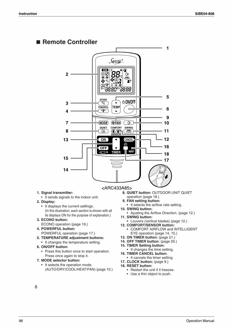
Instruction SiBE04-808
6
Remote Controller
1. Signal transmitter:• It sends signals to the indoor unit.
2. Display:• It displays the current settings.
(In this illustration, each section is shown with all its displays ON for the purpose of explanation.)
3. ECONO button:ECONO operation (page 19.)
4. POWERFUL button:POWERFUL operation (page 17.)
5. TEMPERATURE adjustment buttons:• It changes the temperature setting.
6. ON/OFF button:• Press this button once to start operation.
Press once again to stop it.7. MODE selector button:
• It selects the operation mode.(AUTO/DRY/COOL/HEAT/FAN) (page 10.)
8. QUIET button: OUTDOOR UNIT QUIET operation (page 18.)
9. FAN setting button:• It selects the airflow rate setting.
10. SWING button:• Ajusting the Airflow Direction. (page 12.)
11. SWING button: • Louvers (vertical blades) (page 12.)
12. COMFORT/SENSOR button:• COMFORT AIRFLOW and INTELLIGENT
EYE operation (page 14, 15.)13. ON TIMER button: (page 21.)14. OFF TIMER button: (page 20.)15. TIMER Setting button:
• It changes the time setting.16. TIMER CANCEL button:
• It cancels the timer setting.17. CLOCK button: (page 9.)18. RESET button:
• Restart the unit if it freezes.• Use a thin object to push.
TEMPON/OFF
POWERFUL
MODE FANQUIET SWING
SENSOR
ECONO
COMFORT
TIMER
ON CANCEL
OFF
R
1
2
5
6
910
11
12
16
1817
13
15
14
3
4
7
8
<ARC433A85>
98 Operation Manual
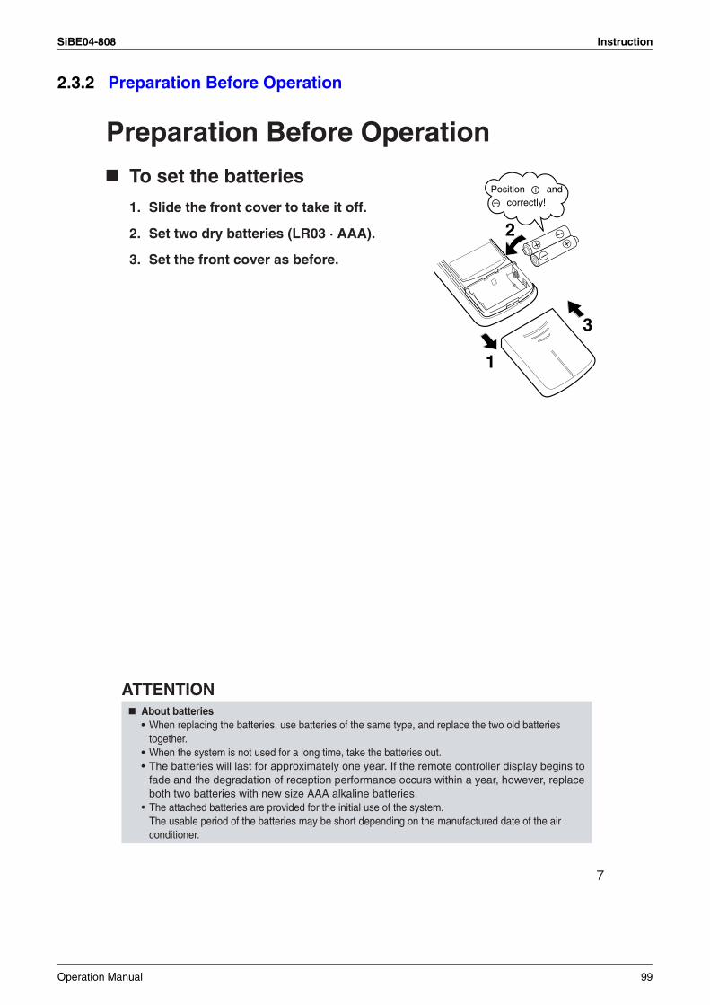
SiBE04-808 Instruction
2.3.2 Preparation Before Operation
7
Preparation Before Operation
To set the batteries
1. Slide the front cover to take it off.
2. Set two dry batteries (LR03 · AAA).
3. Set the front cover as before.
ATTENTIONAbout batteries• When replacing the batteries, use batteries of the same type, and replace the two old batteries
together.• When the system is not used for a long time, take the batteries out.• The batteries will last for approximately one year. If the remote controller display begins to
fade and the degradation of reception performance occurs within a year, however, replace both two batteries with new size AAA alkaline batteries.
• The attached batteries are provided for the initial use of the system.The usable period of the batteries may be short depending on the manufactured date of the air conditioner.
+–
–+
2
3
1
Position + and – correctly!
Operation Manual 99
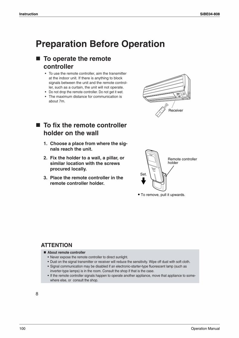
Instruction SiBE04-808
8
Preparation Before Operation
To operate the remote controller• To use the remote controller, aim the transmitter
at the indoor unit. If there is anything to block signals between the unit and the remote control-ler, such as a curtain, the unit will not operate.
• Do not drop the remote controller. Do not get it wet.• The maximum distance for communication is
about 7m.
To fix the remote controller holder on the wall
1. Choose a place from where the sig-nals reach the unit.
2. Fix the holder to a wall, a pillar, or similar location with the screws procured locally.
3. Place the remote controller in the remote controller holder.
ATTENTIONAbout remote controller• Never expose the remote controller to direct sunlight.• Dust on the signal transmitter or receiver will reduce the sensitivity. Wipe off dust with soft cloth.• Signal communication may be disabled if an electronic-starter-type fluorescent lamp (such as
inverter-type lamps) is in the room. Consult the shop if that is the case.• If the remote controller signals happen to operate another appliance, move that appliance to some-
where else, or consult the shop.
Receiver
Remote controller holder
Set.
To remove, pull it upwards.
RR
100 Operation Manual
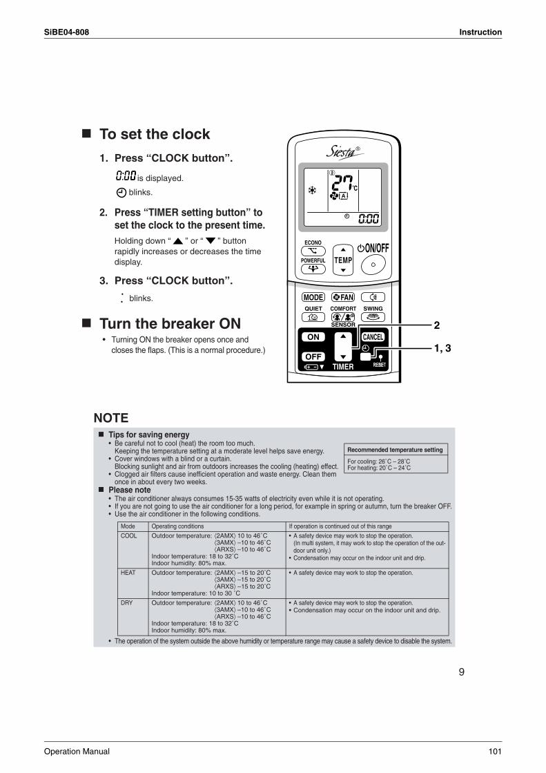
SiBE04-808 Instruction
9
To set the clock
1. Press “CLOCK button”.
is displayed.
blinks.
2. Press “TIMER setting button” to set the clock to the present time.Holding down “ ” or “ ” button rapidly increases or decreases the time display.
3. Press “CLOCK button”.
blinks.
Turn the breaker ON• Turning ON the breaker opens once and
closes the flaps. (This is a normal procedure.)
NOTETips for saving energy• Be careful not to cool (heat) the room too much.
Keeping the temperature setting at a moderate level helps save energy.• Cover windows with a blind or a curtain.
Blocking sunlight and air from outdoors increases the cooling (heating) effect.• Clogged air filters cause inefficient operation and waste energy. Clean them
once in about every two weeks.Please note• The air conditioner always consumes 15-35 watts of electricity even while it is not operating.• If you are not going to use the air conditioner for a long period, for example in spring or autumn, turn the breaker OFF.• Use the air conditioner in the following conditions.
• The operation of the system outside the above humidity or temperature range may cause a safety device to disable the system.
TEMPON/OFF
POWERFUL
MODE FANQUIET SWING
SENSOR
COMFORT
ECONO
TIMER
ON CANCEL
OFF
R
1, 3
2
Recommended temperature setting
For cooling: 26˚C – 28˚CFor heating: 20˚C – 24˚C
Mode Operating conditions If operation is continued out of this range
COOL Outdoor temperature: ⟨2AMX⟩ 10 to 46˚C⟨3AMX⟩ –10 to 46˚C⟨ARXS⟩ –10 to 46˚C
Indoor temperature: 18 to 32˚CIndoor humidity: 80% max.
• A safety device may work to stop the operation.(In multi system, it may work to stop the operation of the out-door unit only.)
• Condensation may occur on the indoor unit and drip.
HEAT Outdoor temperature: ⟨2AMX⟩ –15 to 20˚C⟨3AMX⟩ –15 to 20˚C⟨ARXS⟩ –15 to 20˚C
Indoor temperature: 10 to 30 ˚C
• A safety device may work to stop the operation.
DRY Outdoor temperature: ⟨2AMX⟩ 10 to 46˚C⟨3AMX⟩ –10 to 46˚C⟨ARXS⟩ –10 to 46˚C
Indoor temperature: 18 to 32˚CIndoor humidity: 80% max.
• A safety device may work to stop the operation.• Condensation may occur on the indoor unit and drip.
Operation Manual 101
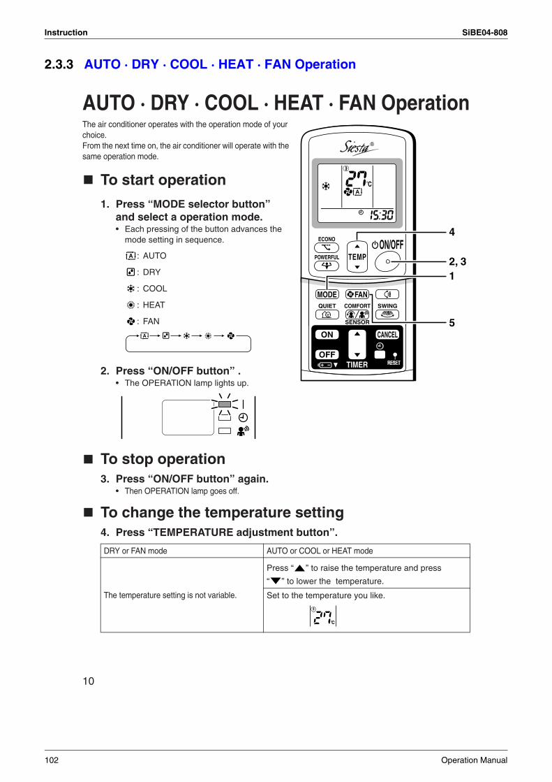
Instruction SiBE04-808
2.3.3 AUTO · DRY · COOL · HEAT · FAN Operation
10
AUTO · DRY · COOL · HEAT · FAN OperationThe air conditioner operates with the operation mode of your choice.From the next time on, the air conditioner will operate with the same operation mode.
To start operation
1. Press “MODE selector button” and select a operation mode.• Each pressing of the button advances the
mode setting in sequence.
: AUTO
: DRY
: COOL
: HEAT
: FAN
2. Press “ON/OFF button” .• The OPERATION lamp lights up.
To stop operation3. Press “ON/OFF button” again.
• Then OPERATION lamp goes off.
To change the temperature setting4. Press “TEMPERATURE adjustment button”.
DRY or FAN mode AUTO or COOL or HEAT mode
The temperature setting is not variable.
Press “ ” to raise the temperature and press
“ ” to lower the temperature.
Set to the temperature you like.
TEMPON/OFF
POWERFUL
MODE FAN
ECONO
QUIET SWING
SENSOR
COMFORT
TIMER
ON CANCEL
OFF
R
2, 31
4
5
C
102 Operation Manual
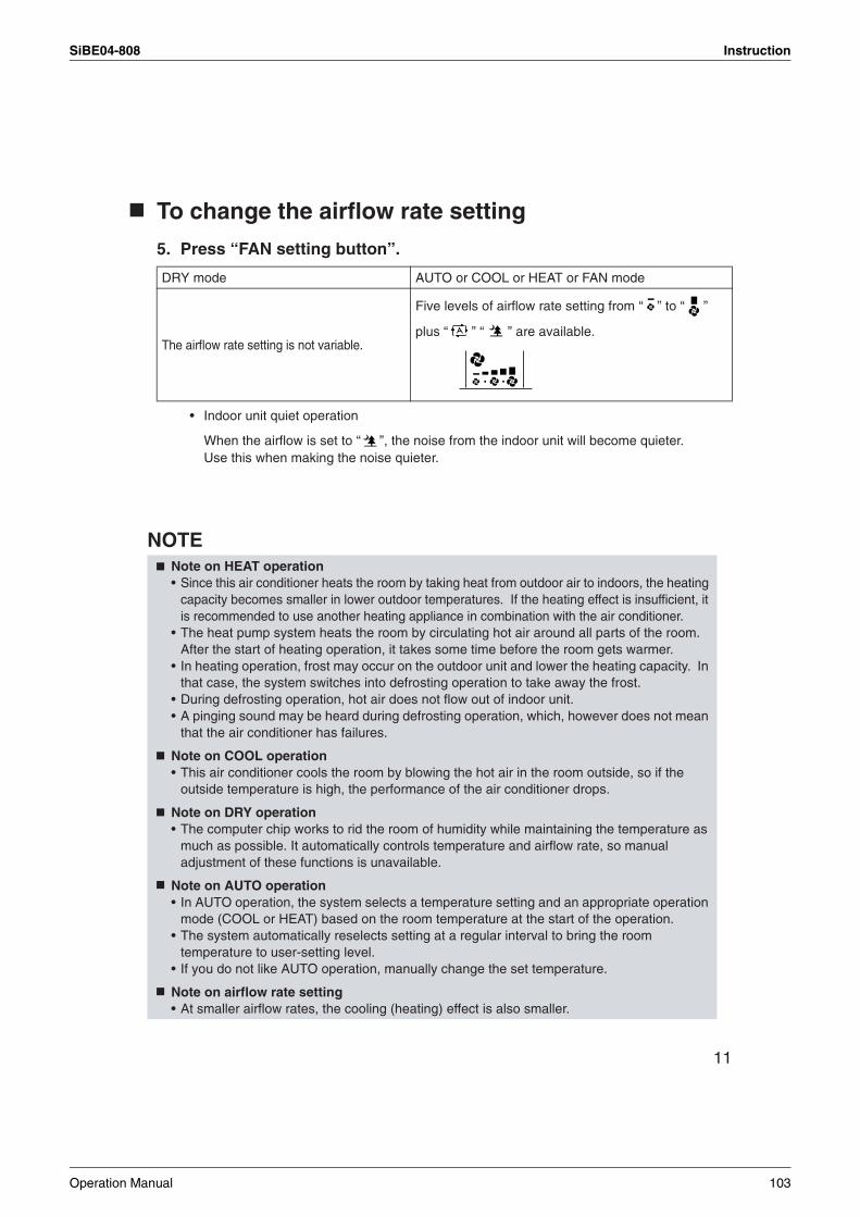
SiBE04-808 Instruction
11
To change the airflow rate setting
5. Press “FAN setting button”.
• Indoor unit quiet operation
When the airflow is set to “ ”, the noise from the indoor unit will become quieter. Use this when making the noise quieter.
NOTE
DRY mode AUTO or COOL or HEAT or FAN mode
The airflow rate setting is not variable.
Five levels of airflow rate setting from “ ” to “ ”
plus “ ” “ ” are available.
Note on HEAT operation• Since this air conditioner heats the room by taking heat from outdoor air to indoors, the heating
capacity becomes smaller in lower outdoor temperatures. If the heating effect is insufficient, it is recommended to use another heating appliance in combination with the air conditioner.
• The heat pump system heats the room by circulating hot air around all parts of the room. After the start of heating operation, it takes some time before the room gets warmer.
• In heating operation, frost may occur on the outdoor unit and lower the heating capacity. In that case, the system switches into defrosting operation to take away the frost.
• During defrosting operation, hot air does not flow out of indoor unit.• A pinging sound may be heard during defrosting operation, which, however does not mean
that the air conditioner has failures.
Note on COOL operation• This air conditioner cools the room by blowing the hot air in the room outside, so if the
outside temperature is high, the performance of the air conditioner drops.
Note on DRY operation• The computer chip works to rid the room of humidity while maintaining the temperature as
much as possible. It automatically controls temperature and airflow rate, so manual adjustment of these functions is unavailable.
Note on AUTO operation• In AUTO operation, the system selects a temperature setting and an appropriate operation
mode (COOL or HEAT) based on the room temperature at the start of the operation.• The system automatically reselects setting at a regular interval to bring the room
temperature to user-setting level.• If you do not like AUTO operation, manually change the set temperature.
Note on airflow rate setting• At smaller airflow rates, the cooling (heating) effect is also smaller.
Operation Manual 103
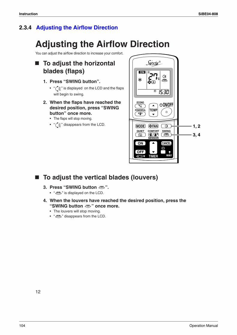
Instruction SiBE04-808
2.3.4 Adjusting the Airflow Direction
12
Adjusting the Airflow DirectionYou can adjust the airflow direction to increase your comfort.
To adjust the horizontal blades (flaps)
1. Press “SWING button”.• “ ” is displayed on the LCD and the flaps
will begin to swing.
2. When the flaps have reached the desired position, press “SWING button” once more.• The flaps will stop moving.
• “ ” disappears from the LCD.
To adjust the vertical blades (louvers) 3. Press “SWING button ”.
• “ ” is displayed on the LCD.
4. When the louvers have reached the desired position, press the “SWING button ” once more.• The louvers will stop moving.• “ ” disappears from the LCD.
TEMPON/OFF
POWERFUL
MODE FANQUIET SWING
SENSOR
COMFORT
ECONO
TIMER
ON CANCEL
OFF
R
1, 2
3, 4
104 Operation Manual
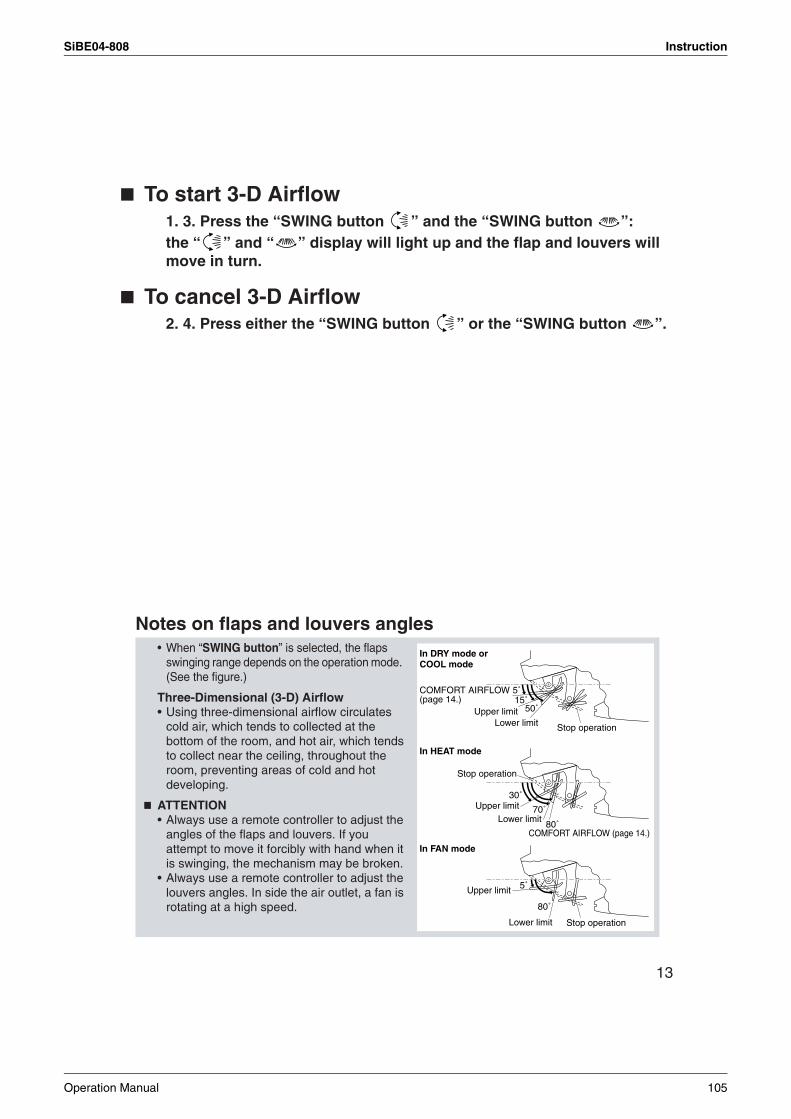
SiBE04-808 Instruction
13
To start 3-D Airflow1. 3. Press the “SWING button ” and the “SWING button ”:the “ ” and “ ” display will light up and the flap and louvers will move in turn.
To cancel 3-D Airflow2. 4. Press either the “SWING button ” or the “SWING button ”.
Notes on flaps and louvers angles• When “SWING button” is selected, the flaps
swinging range depends on the operation mode. (See the figure.)
Three-Dimensional (3-D) Airflow• Using three-dimensional airflow circulates
cold air, which tends to collected at the bottom of the room, and hot air, which tends to collect near the ceiling, throughout the room, preventing areas of cold and hot developing.
ATTENTION• Always use a remote controller to adjust the
angles of the flaps and louvers. If you attempt to move it forcibly with hand when it is swinging, the mechanism may be broken.
• Always use a remote controller to adjust the louvers angles. In side the air outlet, a fan is rotating at a high speed.
5˚
80˚
5˚15˚
50˚
80˚
30˚
70˚
In DRY mode or COOL mode
Upper limit
COMFORT AIRFLOW(page 14.)
COMFORT AIRFLOW (page 14.)
Lower limit
Stop operation
Upper limitLower limit
Upper limit
Lower limit
In HEAT mode
In FAN mode
Stop operation
Stop operation
Operation Manual 105
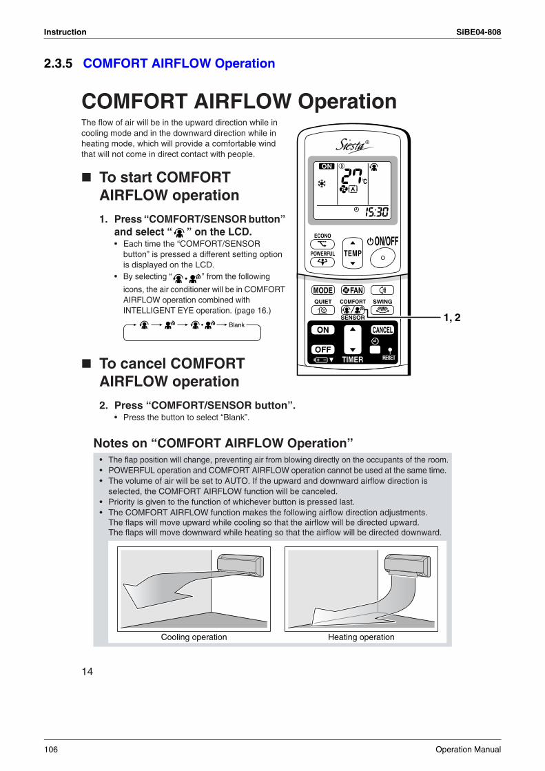
Instruction SiBE04-808
2.3.5 COMFORT AIRFLOW Operation
14
COMFORT AIRFLOW OperationThe flow of air will be in the upward direction while in cooling mode and in the downward direction while in heating mode, which will provide a comfortable wind that will not come in direct contact with people.
To start COMFORT AIRFLOW operation
1. Press “COMFORT/SENSOR button” and select “ ” on the LCD. • Each time the “COMFORT/SENSOR
button” is pressed a different setting option is displayed on the LCD.
• By selecting “ ” from the following
icons, the air conditioner will be in COMFORT AIRFLOW operation combined with INTELLIGENT EYE operation. (page 16.)
To cancel COMFORT AIRFLOW operation
2. Press “COMFORT/SENSOR button”.• Press the button to select “Blank”.
Notes on “COMFORT AIRFLOW Operation” • The flap position will change, preventing air from blowing directly on the occupants of the room.• POWERFUL operation and COMFORT AIRFLOW operation cannot be used at the same time. • The volume of air will be set to AUTO. If the upward and downward airflow direction is
selected, the COMFORT AIRFLOW function will be canceled.• Priority is given to the function of whichever button is pressed last. • The COMFORT AIRFLOW function makes the following airflow direction adjustments.
The flaps will move upward while cooling so that the airflow will be directed upward. The flaps will move downward while heating so that the airflow will be directed downward.
TEMPON/OFF
POWERFUL
MODE FANQUIET SWING
SENSOR
COMFORT
ECONO
TIMER
ON CANCEL
OFF
R
1, 2Blank
Cooling operation Heating operation
106 Operation Manual
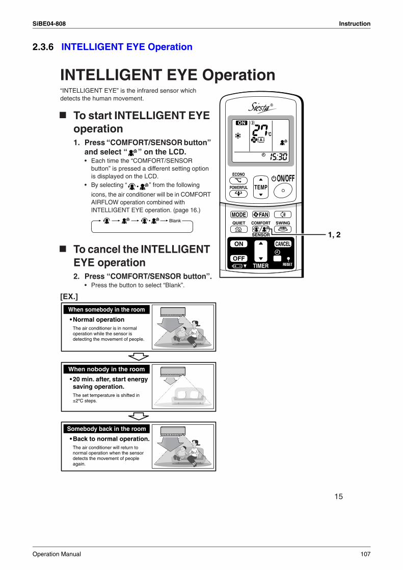
SiBE04-808 Instruction
2.3.6 INTELLIGENT EYE Operation
15
INTELLIGENT EYE Operation“INTELLIGENT EYE” is the infrared sensor which detects the human movement.
To start INTELLIGENT EYE operation1. Press “COMFORT/SENSOR button”
and select “ ” on the LCD. • Each time the “COMFORT/SENSOR
button” is pressed a different setting option is displayed on the LCD.
• By selecting “ ” from the following
icons, the air conditioner will be in COMFORT AIRFLOW operation combined with INTELLIGENT EYE operation. (page 16.)
To cancel the INTELLIGENT EYE operation2. Press “COMFORT/SENSOR button”.
• Press the button to select “Blank”.
[EX.]
TEMPON/OFF
POWERFUL
MODE FANQUIET SWING
SENSOR
COMFORT
ECONO
TIMER
ON CANCEL
OFF
R
1, 2
Blank
Somebody back in the room
• Back to normal operation.The air conditioner will return to normal operation when the sensor detects the movement of people again.
When somebody in the room
• Normal operationThe air conditioner is in normal operation while the sensor is detecting the movement of people.
When nobody in the room
• 20 min. after, start energy saving operation.The set temperature is shifted in ±2ºC steps.
Operation Manual 107
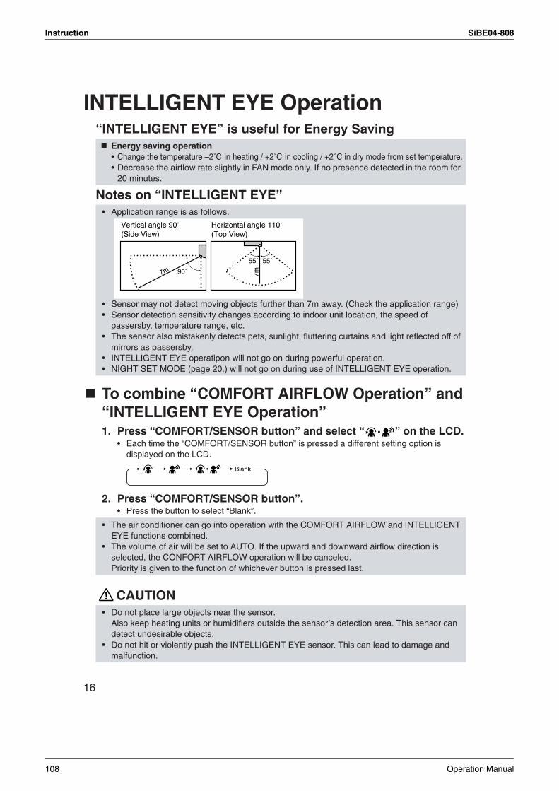
Instruction SiBE04-808
16
INTELLIGENT EYE Operation“INTELLIGENT EYE” is useful for Energy Saving
Notes on “INTELLIGENT EYE”
To combine “COMFORT AIRFLOW Operation” and “INTELLIGENT EYE Operation”1. Press “COMFORT/SENSOR button” and select “ ” on the LCD.
• Each time the “COMFORT/SENSOR button” is pressed a different setting option is displayed on the LCD.
2. Press “COMFORT/SENSOR button”.• Press the button to select “Blank”.
CAUTION
Energy saving operation• Change the temperature –2˚C in heating / +2˚C in cooling / +2˚C in dry mode from set temperature.• Decrease the airflow rate slightly in FAN mode only. If no presence detected in the room for
20 minutes.
• Application range is as follows.
• Sensor may not detect moving objects further than 7m away. (Check the application range)• Sensor detection sensitivity changes according to indoor unit location, the speed of
passersby, temperature range, etc.• The sensor also mistakenly detects pets, sunlight, fluttering curtains and light reflected off of
mirrors as passersby.• INTELLIGENT EYE operatipon will not go on during powerful operation.• NIGHT SET MODE (page 20.) will not go on during use of INTELLIGENT EYE operation.
• The air conditioner can go into operation with the COMFORT AIRFLOW and INTELLIGENT EYE functions combined.
• The volume of air will be set to AUTO. If the upward and downward airflow direction is selected, the CONFORT AIRFLOW operation will be canceled. Priority is given to the function of whichever button is pressed last.
• Do not place large objects near the sensor.Also keep heating units or humidifiers outside the sensor’s detection area. This sensor can detect undesirable objects.
• Do not hit or violently push the INTELLIGENT EYE sensor. This can lead to damage and malfunction.
90˚
55˚7m
55˚
7m
Vertical angle 90˚(Side View)
Horizontal angle 110˚(Top View)
Blank
108 Operation Manual
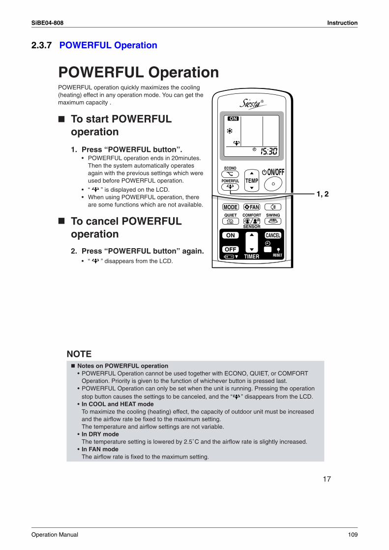
SiBE04-808 Instruction
2.3.7 POWERFUL Operation
17
POWERFUL OperationPOWERFUL operation quickly maximizes the cooling (heating) effect in any operation mode. You can get the maximum capacity .
To start POWERFUL operation
1. Press “POWERFUL button”.• POWERFUL operation ends in 20minutes.
Then the system automatically operates again with the previous settings which were used before POWERFUL operation.
• “ ” is displayed on the LCD.• When using POWERFUL operation, there
are some functions which are not available.
To cancel POWERFUL operation
2. Press “POWERFUL button” again.• “ ” disappears from the LCD.
NOTENotes on POWERFUL operation• POWERFUL Operation cannot be used together with ECONO, QUIET, or COMFORT
Operation. Priority is given to the function of whichever button is pressed last.• POWERFUL Operation can only be set when the unit is running. Pressing the operation
stop button causes the settings to be canceled, and the “ ” disappears from the LCD.• In COOL and HEAT mode
To maximize the cooling (heating) effect, the capacity of outdoor unit must be increased and the airflow rate be fixed to the maximum setting.The temperature and airflow settings are not variable.
• In DRY modeThe temperature setting is lowered by 2.5˚C and the airflow rate is slightly increased.
• In FAN modeThe airflow rate is fixed to the maximum setting.
TEMPON/OFF
POWERFUL
MODE FANQUIET SWING
SENSOR
COMFORT
ECONO
TIMER
ON CANCEL
OFF
R
1, 2
Operation Manual 109
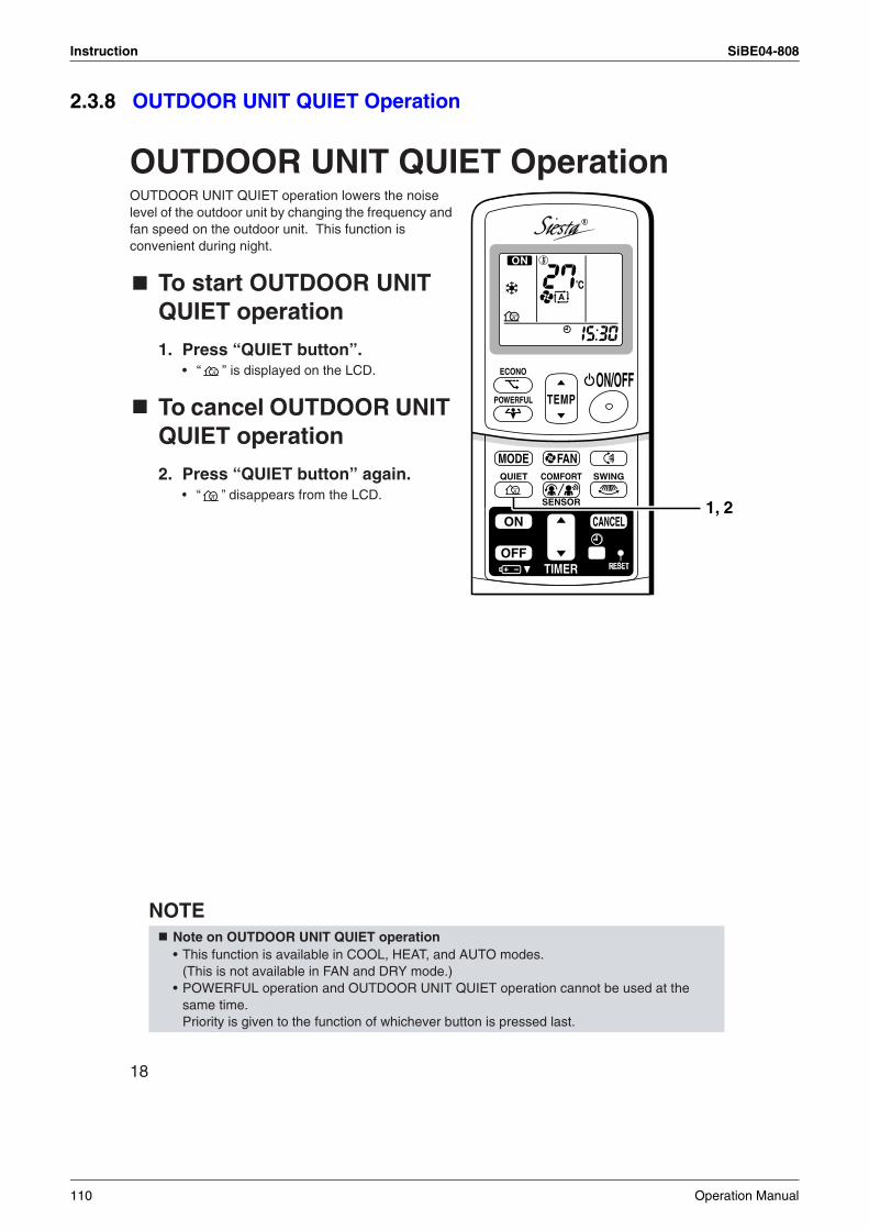
Instruction SiBE04-808
2.3.8 OUTDOOR UNIT QUIET Operation
18
OUTDOOR UNIT QUIET OperationOUTDOOR UNIT QUIET operation lowers the noise level of the outdoor unit by changing the frequency and fan speed on the outdoor unit. This function is convenient during night.
To start OUTDOOR UNIT QUIET operation
1. Press “QUIET button”.• “ ” is displayed on the LCD.
To cancel OUTDOOR UNIT QUIET operation
2. Press “QUIET button” again.• “ ” disappears from the LCD.
NOTENote on OUTDOOR UNIT QUIET operation• This function is available in COOL, HEAT, and AUTO modes.
(This is not available in FAN and DRY mode.)• POWERFUL operation and OUTDOOR UNIT QUIET operation cannot be used at the
same time. Priority is given to the function of whichever button is pressed last.
TEMPON/OFF
POWERFUL
MODE FANQUIET SWING
SENSOR
COMFORT
ECONO
TIMER
ON CANCEL
OFF
R
1, 2
110 Operation Manual
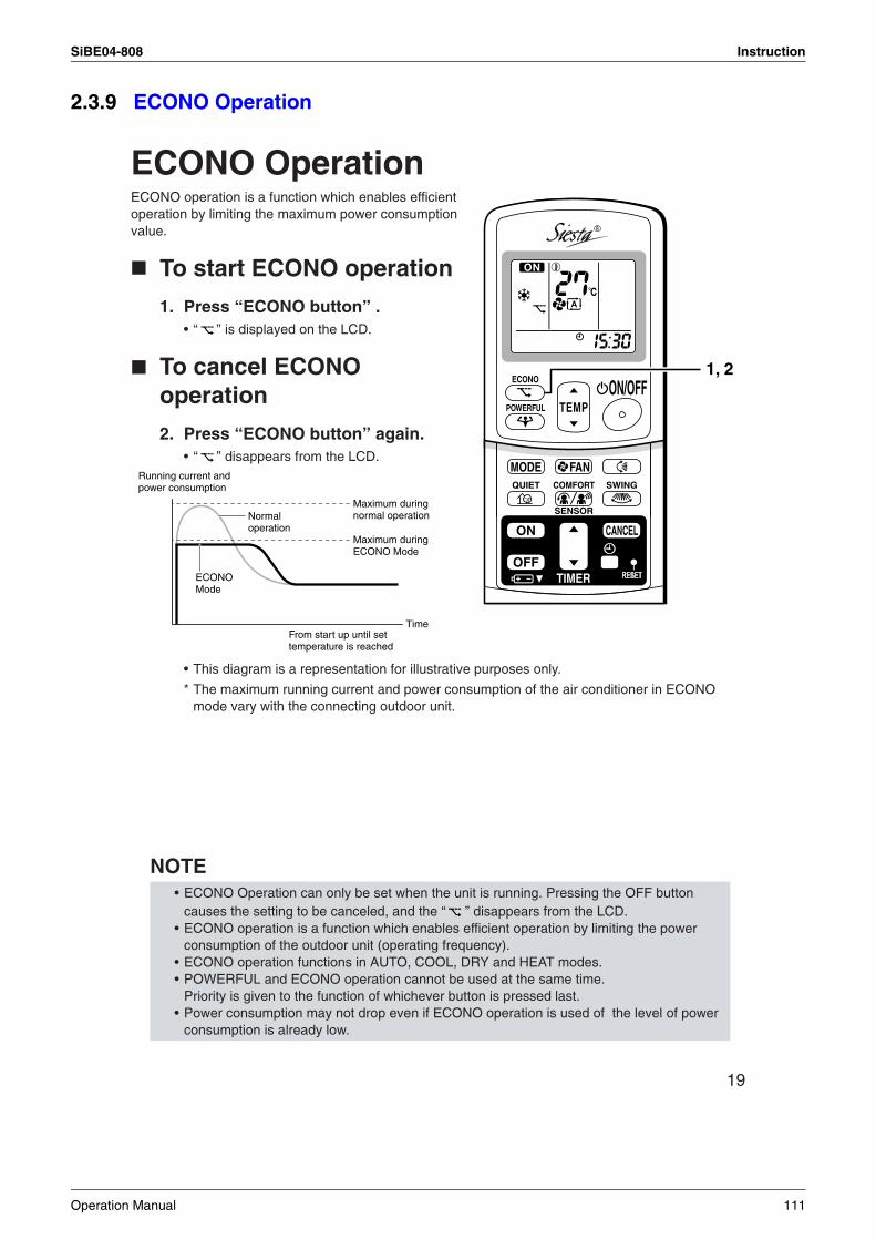
SiBE04-808 Instruction
2.3.9 ECONO Operation
19
ECONO OperationECONO operation is a function which enables efficient operation by limiting the maximum power consumption value.
To start ECONO operation
1. Press “ECONO button” .• “ ” is displayed on the LCD.
To cancel ECONO operation
2. Press “ECONO button” again.• “ ” disappears from the LCD.
• This diagram is a representation for illustrative purposes only.
* The maximum running current and power consumption of the air conditioner in ECONO mode vary with the connecting outdoor unit.
NOTE • ECONO Operation can only be set when the unit is running. Pressing the OFF button
causes the setting to be canceled, and the “ ” disappears from the LCD.• ECONO operation is a function which enables efficient operation by limiting the power
consumption of the outdoor unit (operating frequency).• ECONO operation functions in AUTO, COOL, DRY and HEAT modes. • POWERFUL and ECONO operation cannot be used at the same time.
Priority is given to the function of whichever button is pressed last.• Power consumption may not drop even if ECONO operation is used of the level of power
consumption is already low.
TEMPON/OFF
POWERFUL
MODE FANQUIET SWING
SENSOR
COMFORT
ECONO
TIMER
ON CANCEL
OFF
R
1, 2
Running current and power consumption
From start up until set temperature is reached
Time
Maximum during normal operation
Maximum during ECONO Mode
Normal operation
ECONO Mode
Operation Manual 111
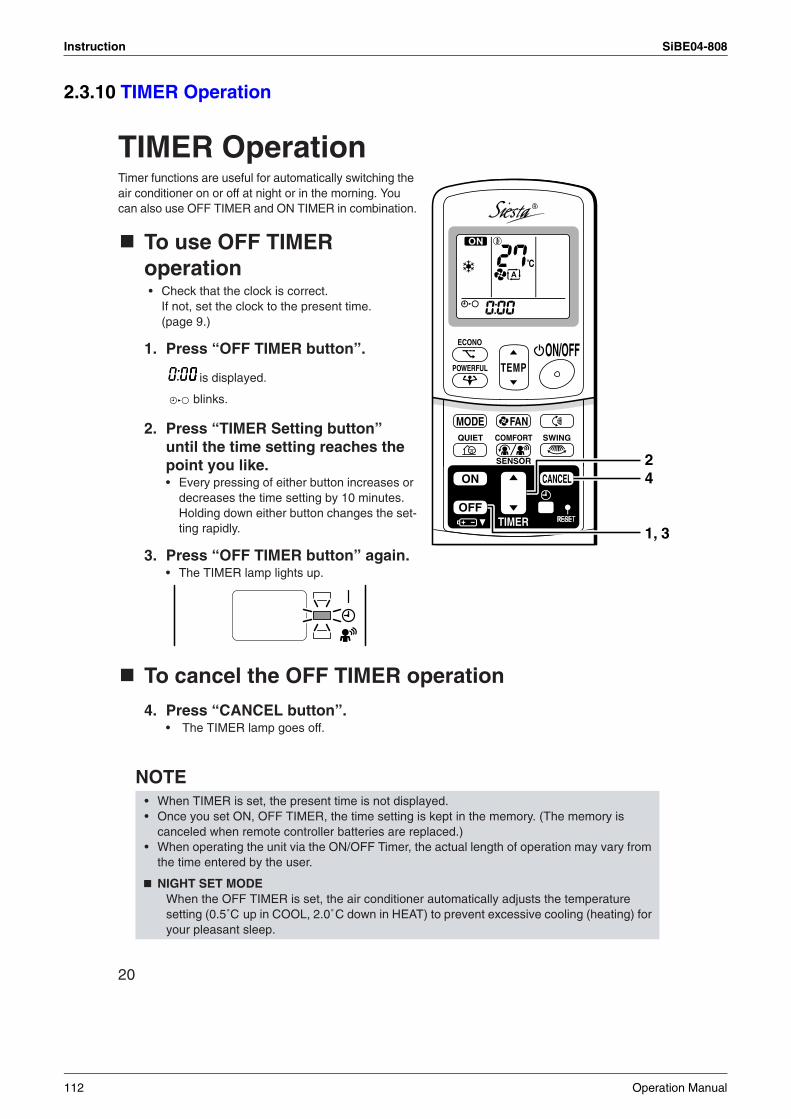
Instruction SiBE04-808
2.3.10 TIMER Operation
20
TIMER OperationTimer functions are useful for automatically switching the air conditioner on or off at night or in the morning. You can also use OFF TIMER and ON TIMER in combination.
To use OFF TIMER operation• Check that the clock is correct.
If not, set the clock to the present time. (page 9.)
1. Press “OFF TIMER button”.
is displayed.
blinks.
2. Press “TIMER Setting button” until the time setting reaches the point you like.• Every pressing of either button increases or
decreases the time setting by 10 minutes. Holding down either button changes the set-ting rapidly.
3. Press “OFF TIMER button” again.• The TIMER lamp lights up.
To cancel the OFF TIMER operation
4. Press “CANCEL button”.• The TIMER lamp goes off.
NOTE • When TIMER is set, the present time is not displayed.• Once you set ON, OFF TIMER, the time setting is kept in the memory. (The memory is
canceled when remote controller batteries are replaced.)• When operating the unit via the ON/OFF Timer, the actual length of operation may vary from
the time entered by the user.
NIGHT SET MODEWhen the OFF TIMER is set, the air conditioner automatically adjusts the temperature setting (0.5˚C up in COOL, 2.0˚C down in HEAT) to prevent excessive cooling (heating) for your pleasant sleep.
TEMPON/OFF
POWERFUL
MODE FANQUIET SWING
SENSOR
COMFORT
ECONO
TIMER
ON CANCEL
OFF
R
42
1, 3
112 Operation Manual
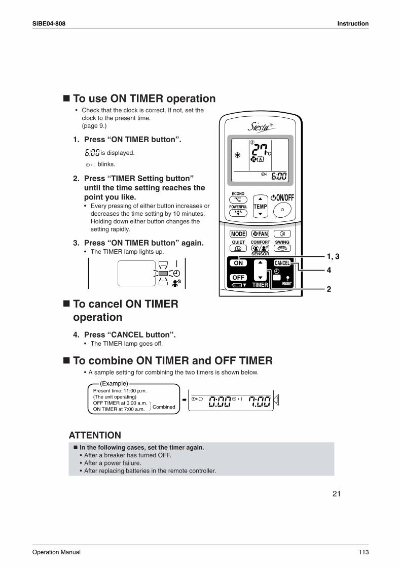
SiBE04-808 Instruction
21
To use ON TIMER operation• Check that the clock is correct. If not, set the
clock to the present time.(page 9.)
1. Press “ON TIMER button”.
is displayed.
blinks.
2. Press “TIMER Setting button” until the time setting reaches the point you like.• Every pressing of either button increases or
decreases the time setting by 10 minutes. Holding down either button changes the setting rapidly.
3. Press “ON TIMER button” again.• The TIMER lamp lights up.
To cancel ON TIMER operation
4. Press “CANCEL button”.• The TIMER lamp goes off.
To combine ON TIMER and OFF TIMER• A sample setting for combining the two timers is shown below.
ATTENTION In the following cases, set the timer again.• After a breaker has turned OFF.• After a power failure.• After replacing batteries in the remote controller.
TEMPON/OFF
POWERFUL
MODE FANQUIET SWING
SENSOR
COMFORT
ECONO
TIMER
ON CANCEL
OFF
R
2
1, 3
4D
ispl
ay
(Example)Present time: 11:00 p.m. (The unit operating)OFF TIMER at 0:00 a.m.ON TIMER at 7:00 a.m. Combined
Operation Manual 113
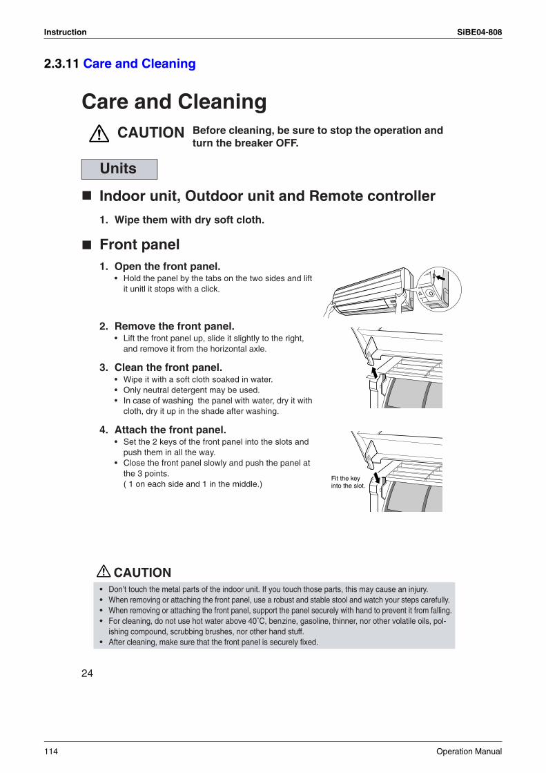
Instruction SiBE04-808
2.3.11 Care and Cleaning
24
Care and CleaningCAUTION
Indoor unit, Outdoor unit and Remote controller
1. Wipe them with dry soft cloth.
Front panel1. Open the front panel.
• Hold the panel by the tabs on the two sides and lift it unitl it stops with a click.
2. Remove the front panel. • Lift the front panel up, slide it slightly to the right,
and remove it from the horizontal axle.
3. Clean the front panel.• Wipe it with a soft cloth soaked in water.• Only neutral detergent may be used.• In case of washing the panel with water, dry it with
cloth, dry it up in the shade after washing.
4. Attach the front panel. • Set the 2 keys of the front panel into the slots and
push them in all the way.• Close the front panel slowly and push the panel at
the 3 points.( 1 on each side and 1 in the middle.)
CAUTION
Units
• Don’t touch the metal parts of the indoor unit. If you touch those parts, this may cause an injury.• When removing or attaching the front panel, use a robust and stable stool and watch your steps carefully. • When removing or attaching the front panel, support the panel securely with hand to prevent it from falling.• For cleaning, do not use hot water above 40˚C, benzine, gasoline, thinner, nor other volatile oils, pol-
ishing compound, scrubbing brushes, nor other hand stuff.• After cleaning, make sure that the front panel is securely fixed.
Before cleaning, be sure to stop the operation and turn the breaker OFF.
Fit the key into the slot.
114 Operation Manual
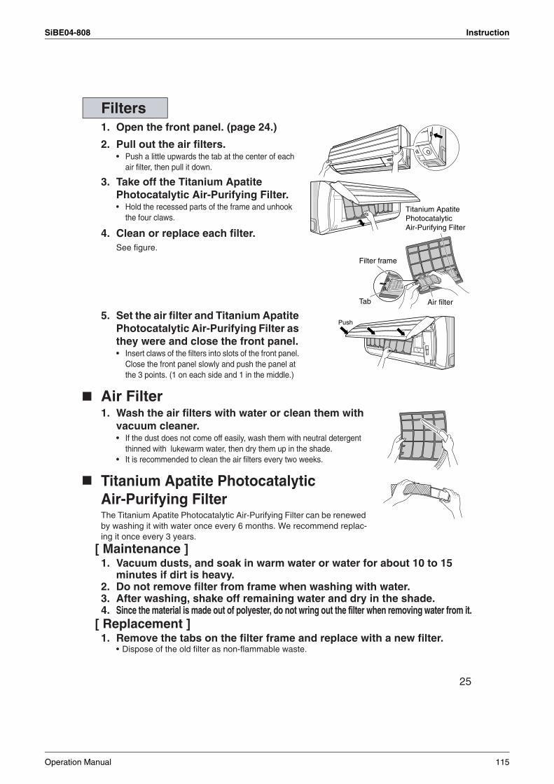
SiBE04-808 Instruction
25
1. Open the front panel. (page 24.)
2. Pull out the air filters.• Push a little upwards the tab at the center of each
air filter, then pull it down.
3. Take off the Titanium Apatite Photocatalytic Air-Purifying Filter.• Hold the recessed parts of the frame and unhook
the four claws.
4. Clean or replace each filter.See figure.
5. Set the air filter and Titanium Apatite Photocatalytic Air-Purifying Filter as they were and close the front panel.• Insert claws of the filters into slots of the front panel.
Close the front panel slowly and push the panel at the 3 points. (1 on each side and 1 in the middle.)
Air Filter1. Wash the air filters with water or clean them with
vacuum cleaner. • If the dust does not come off easily, wash them with neutral detergent
thinned with lukewarm water, then dry them up in the shade.• It is recommended to clean the air filters every two weeks.
Titanium Apatite Photocatalytic Air-Purifying Filter The Titanium Apatite Photocatalytic Air-Purifying Filter can be renewed by washing it with water once every 6 months. We recommend replac-ing it once every 3 years.
[ Maintenance ]1. Vacuum dusts, and soak in warm water or water for about 10 to 15
minutes if dirt is heavy.2. Do not remove filter from frame when washing with water.3. After washing, shake off remaining water and dry in the shade.4. Since the material is made out of polyester, do not wring out the filter when removing water from it.
[ Replacement ]1. Remove the tabs on the filter frame and replace with a new filter.
• Dispose of the old filter as non-flammable waste.
Filters
Titanium Apatite Photocatalytic Air-Purifying Filter
Filter frame
Air filterTab
Push
Operation Manual 115
Instruction SiBE04-808
26
NOTE
Check
Before a long idle period
1. Operate the “FAN only” for several hours on a fine day to dry out the inside.• Press “MODE selector button” and select “FAN” operation.
• Press “ON/OFF button” and start operation.
2. After operation stops, turn off the breaker for the room air conditioner.
3. Clean the air filters and set them again.
4. Take out batteries from the remote controller.
• Operation with dirty filters: (1) cannot deodorize the air. (2) cannot clean the air. (3) results in poor heating or cooling. (4) may cause odour.
• To order Titanium Apatite Photocatalytic Air-Purifying Filter contact to the service shop there you bought the air conditioner.
• Dispose of the old filter as non-flammable waste.
Check that the base, stand and other fittings of the outdoor unit are not decayed or corroded.
Check that nothing blocks the air inlets and the outlets of the indoor unit and the outdoor unit.
Check that the drain comes smoothly out of the drain hose during COOL or DRY operation.• If no drain water is seen, water may be leaking from the indoor unit. Stop operation and consult the ser-
vice shop if this is the case.
Item Part No.
Titanium Apatite Photocatalytic Air-Purifying Filter (without frame) 1 set KAF970A46
116 Operation Manual
SiBE04-808 Instruction
2.3.12 Troubleshooting
27
Trouble Shooting
The following cases are not air conditioner troubles but have some reasons. You may just continue using it.
These cases are not troubles.
Case ExplanationOperation does not start soon.• When ON/OFF button was
pressed soon after operation was stopped.
• When the mode was reselected.
• This is to protect the air conditioner.You should wait for about 3 minutes.
Hot air does not flow out soon after the start of heating operation.
• The air conditioner is warming up. You should wait for 1 to 4 minutes.(The system is designed to start discharging air only after it has reached a certain temperature.)
The heating operation stops suddenly and a flowing sound is heard.
• The system is taking away the frost on the outdoor unit.You should wait for about 3 to 8 minutes.
The outdoor unit emits water or steam.
In HEAT mode• The frost on the outdoor unit melts into water or steam
when the air conditioner is in defrost operation.In COOL or DRY mode• Moisture in the air condenses into water on the cool
surface of outdoor unit piping and drips.
Mist comes out of the indoor unit.
This happens when the air in the room is cooled into mist by the cold airflow during cooling operation.
The indoor unit gives out odour. This happens when smells of the room, furniture, or cigarettes are absorbed into the unit and discharged with the airflow.(If this happens, we recommend you to have the indoor unit washed by a technician. Consult the service shop where you bought the air conditioner.)
The outdoor fan rotates while the air conditioner is not in operation.
After operation is stopped:• The outdoor fan continues rotating for another 60
seconds for system protection.While the air conditioner is not in operation:• When the outdoor temperature is very high, the outdoor
fan starts rotating for system protection.
The operation stopped suddenly.(OPERATION lamp is on.)
For system protection, the air conditioner may stop operating on a sudden large voltage fluctuation.It automatically resumes operation in about 3 minutes.
No remote controller signals are displayed.The remote controller sensitivity is low.The display is low in contrast or blacked out.The display runs out of control.
• The batteries are dying and the remote controller is malfunc-tioning. Replace all the batteries with new size AAA alkaline batteries. For details, refer to “To set the batteries” of this manual. (page 7.)
* If the reset button is provided, press the reset button after the batteries are replaced.
Operation Manual 117
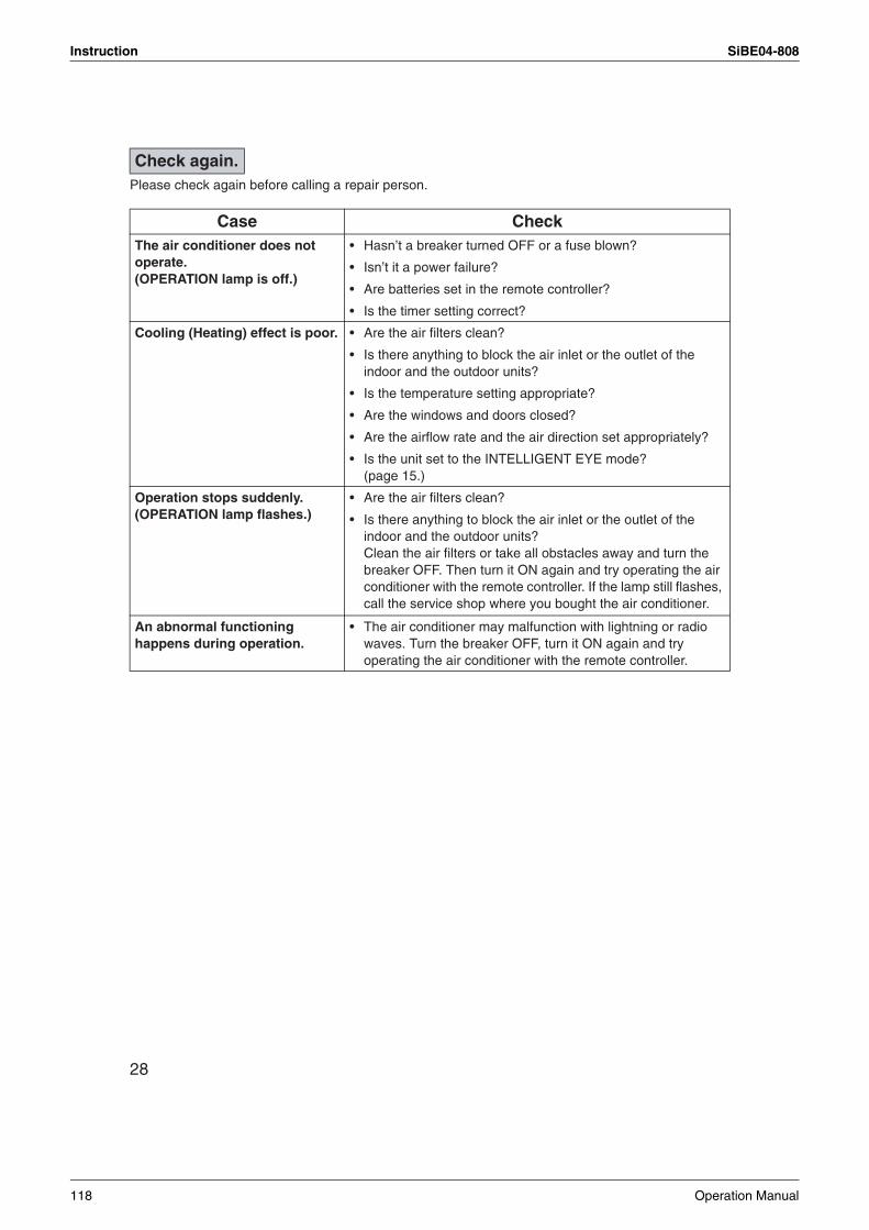
Instruction SiBE04-808
28
Please check again before calling a repair person.
Check again.
Case CheckThe air conditioner does not operate.(OPERATION lamp is off.)
• Hasn’t a breaker turned OFF or a fuse blown?
• Isn’t it a power failure?
• Are batteries set in the remote controller?
• Is the timer setting correct?
Cooling (Heating) effect is poor. • Are the air filters clean?
• Is there anything to block the air inlet or the outlet of the indoor and the outdoor units?
• Is the temperature setting appropriate?
• Are the windows and doors closed?
• Are the airflow rate and the air direction set appropriately?
• Is the unit set to the INTELLIGENT EYE mode?(page 15.)
Operation stops suddenly.(OPERATION lamp flashes.)
• Are the air filters clean?
• Is there anything to block the air inlet or the outlet of the indoor and the outdoor units?Clean the air filters or take all obstacles away and turn the breaker OFF. Then turn it ON again and try operating the air conditioner with the remote controller. If the lamp still flashes, call the service shop where you bought the air conditioner.
An abnormal functioninghappens during operation.
• The air conditioner may malfunction with lightning or radio waves. Turn the breaker OFF, turn it ON again and try operating the air conditioner with the remote controller.
118 Operation Manual
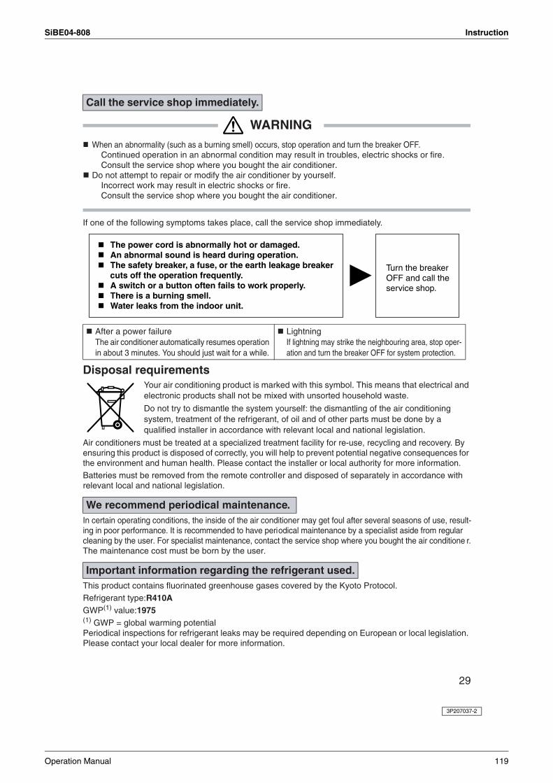
SiBE04-808 Instruction
29
WARNINGWhen an abnormality (such as a burning smell) occurs, stop operation and turn the breaker OFF.
Continued operation in an abnormal condition may result in troubles, electric shocks or fire.Consult the service shop where you bought the air conditioner.
Do not attempt to repair or modify the air conditioner by yourself.Incorrect work may result in electric shocks or fire.Consult the service shop where you bought the air conditioner.
If one of the following symptoms takes place, call the service shop immediately.
Disposal requirementsYour air conditioning product is marked with this symbol. This means that electrical and electronic products shall not be mixed with unsorted household waste.
Do not try to dismantle the system yourself: the dismantling of the air conditioning system, treatment of the refrigerant, of oil and of other parts must be done by a qualified installer in accordance with relevant local and national legislation.
Air conditioners must be treated at a specialized treatment facility for re-use, recycling and recovery. By ensuring this product is disposed of correctly, you will help to prevent potential negative consequences for the environment and human health. Please contact the installer or local authority for more information. Batteries must be removed from the remote controller and disposed of separately in accordance with relevant local and national legislation.
In certain operating conditions, the inside of the air conditioner may get foul after several seasons of use, result-ing in poor performance. It is recommended to have periodical maintenance by a specialist aside from regular cleaning by the user. For specialist maintenance, contact the service shop where you bought the air conditione r.The maintenance cost must be born by the user.
This product contains fluorinated greenhouse gases covered by the Kyoto Protocol.Refrigerant type:R410AGWP(1) value:1975(1) GWP = global warming potentialPeriodical inspections for refrigerant leaks may be required depending on European or local legislation. Please contact your local dealer for more information.
Call the service shop immediately.
After a power failureThe air conditioner automatically resumes operation in about 3 minutes. You should just wait for a while.
LightningIf lightning may strike the neighbouring area, stop oper-ation and turn the breaker OFF for system protection.
We recommend periodical maintenance.
Important information regarding the refrigerant used.
The power cord is abnormally hot or damaged.An abnormal sound is heard during operation.The safety breaker, a fuse, or the earth leakage breaker cuts off the operation frequently. A switch or a button often fails to work properly.There is a burning smell.Water leaks from the indoor unit.
Turn the breaker OFF and call the service shop.
3P207037-2
Operation Manual 119

Instruction SiBE04-808
120 Operation Manual
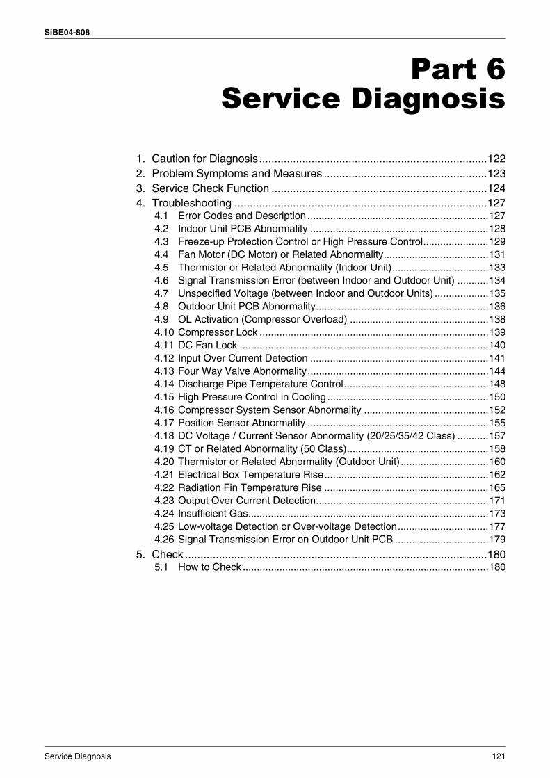
SiBE04-808
Service Diagnosis 121
Part 6Service Diagnosis
1. Caution for Diagnosis..........................................................................1222. Problem Symptoms and Measures .....................................................1233. Service Check Function ......................................................................1244. Troubleshooting ..................................................................................127
4.1 Error Codes and Description ................................................................1274.2 Indoor Unit PCB Abnormality ...............................................................1284.3 Freeze-up Protection Control or High Pressure Control.......................1294.4 Fan Motor (DC Motor) or Related Abnormality.....................................1314.5 Thermistor or Related Abnormality (Indoor Unit)..................................1334.6 Signal Transmission Error (between Indoor and Outdoor Unit) ...........1344.7 Unspecified Voltage (between Indoor and Outdoor Units) ...................1354.8 Outdoor Unit PCB Abnormality.............................................................1364.9 OL Activation (Compressor Overload) .................................................1384.10 Compressor Lock .................................................................................1394.11 DC Fan Lock ........................................................................................1404.12 Input Over Current Detection ...............................................................1414.13 Four Way Valve Abnormality................................................................1444.14 Discharge Pipe Temperature Control...................................................1484.15 High Pressure Control in Cooling .........................................................1504.16 Compressor System Sensor Abnormality ............................................1524.17 Position Sensor Abnormality ................................................................1554.18 DC Voltage / Current Sensor Abnormality (20/25/35/42 Class) ...........1574.19 CT or Related Abnormality (50 Class)..................................................1584.20 Thermistor or Related Abnormality (Outdoor Unit)...............................1604.21 Electrical Box Temperature Rise..........................................................1624.22 Radiation Fin Temperature Rise ..........................................................1654.23 Output Over Current Detection.............................................................1714.24 Insufficient Gas.....................................................................................1734.25 Low-voltage Detection or Over-voltage Detection................................1774.26 Signal Transmission Error on Outdoor Unit PCB .................................179
5. Check ..................................................................................................1805.1 How to Check .......................................................................................180
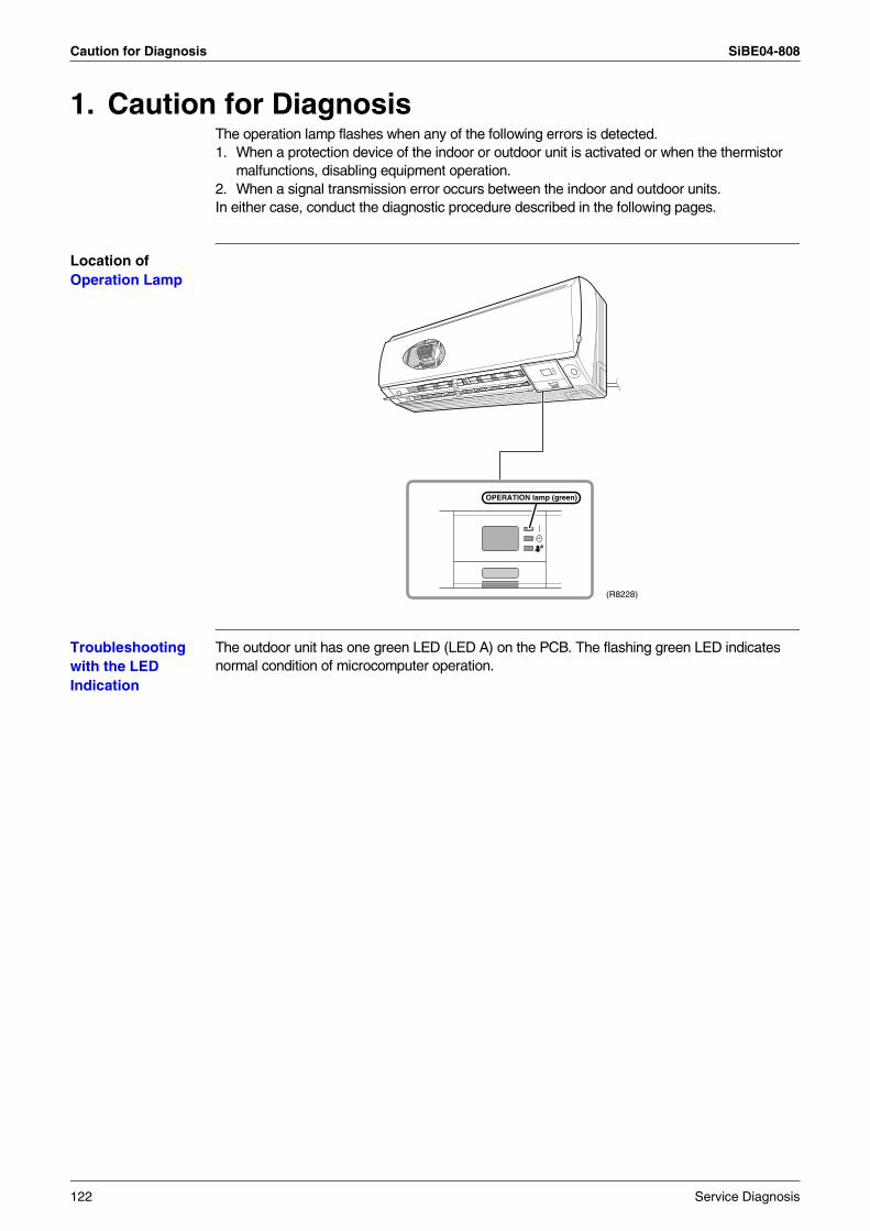
Caution for Diagnosis SiBE04-808
1. Caution for DiagnosisThe operation lamp flashes when any of the following errors is detected.1. When a protection device of the indoor or outdoor unit is activated or when the thermistor
malfunctions, disabling equipment operation.2. When a signal transmission error occurs between the indoor and outdoor units.In either case, conduct the diagnostic procedure described in the following pages.
Location of Operation Lamp
Troubleshooting with the LED Indication
The outdoor unit has one green LED (LED A) on the PCB. The flashing green LED indicates normal condition of microcomputer operation.
(R8228)
OPERATION lamp (green)
122 Service Diagnosis
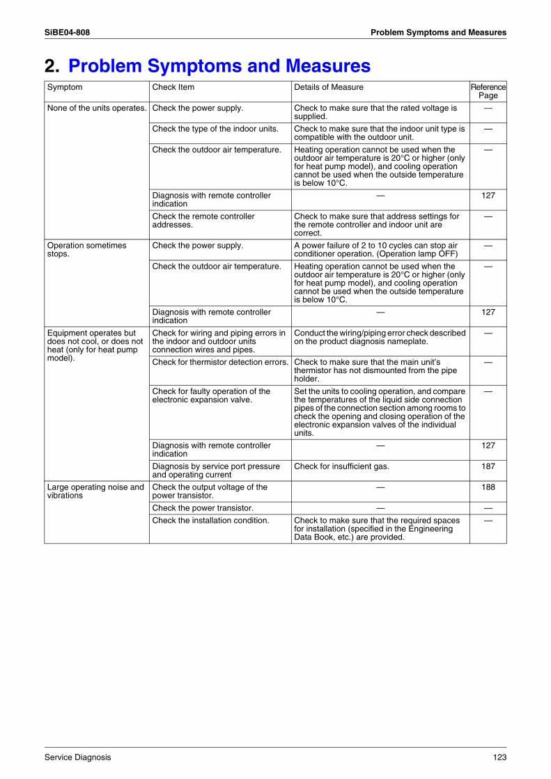
SiBE04-808 Problem Symptoms and Measures
2. Problem Symptoms and MeasuresSymptom Check Item Details of Measure Reference
Page
None of the units operates. Check the power supply. Check to make sure that the rated voltage is supplied.
—
Check the type of the indoor units. Check to make sure that the indoor unit type is compatible with the outdoor unit.
—
Check the outdoor air temperature. Heating operation cannot be used when the outdoor air temperature is 20°C or higher (only for heat pump model), and cooling operation cannot be used when the outside temperature is below 10°C.
—
Diagnosis with remote controller indication
— 127
Check the remote controller addresses.
Check to make sure that address settings for the remote controller and indoor unit are correct.
—
Operation sometimes stops.
Check the power supply. A power failure of 2 to 10 cycles can stop air conditioner operation. (Operation lamp OFF)
—
Check the outdoor air temperature. Heating operation cannot be used when the outdoor air temperature is 20°C or higher (only for heat pump model), and cooling operation cannot be used when the outside temperature is below 10°C.
—
Diagnosis with remote controller indication
— 127
Equipment operates but does not cool, or does not heat (only for heat pump model).
Check for wiring and piping errors in the indoor and outdoor units connection wires and pipes.
Conduct the wiring/piping error check described on the product diagnosis nameplate.
—
Check for thermistor detection errors. Check to make sure that the main unit’s thermistor has not dismounted from the pipe holder.
—
Check for faulty operation of the electronic expansion valve.
Set the units to cooling operation, and compare the temperatures of the liquid side connection pipes of the connection section among rooms to check the opening and closing operation of the electronic expansion valves of the individual units.
—
Diagnosis with remote controller indication
— 127
Diagnosis by service port pressure and operating current
Check for insufficient gas. 187
Large operating noise and vibrations
Check the output voltage of the power transistor.
— 188
Check the power transistor. — —
Check the installation condition. Check to make sure that the required spaces for installation (specified in the Engineering Data Book, etc.) are provided.
—
Service Diagnosis 123
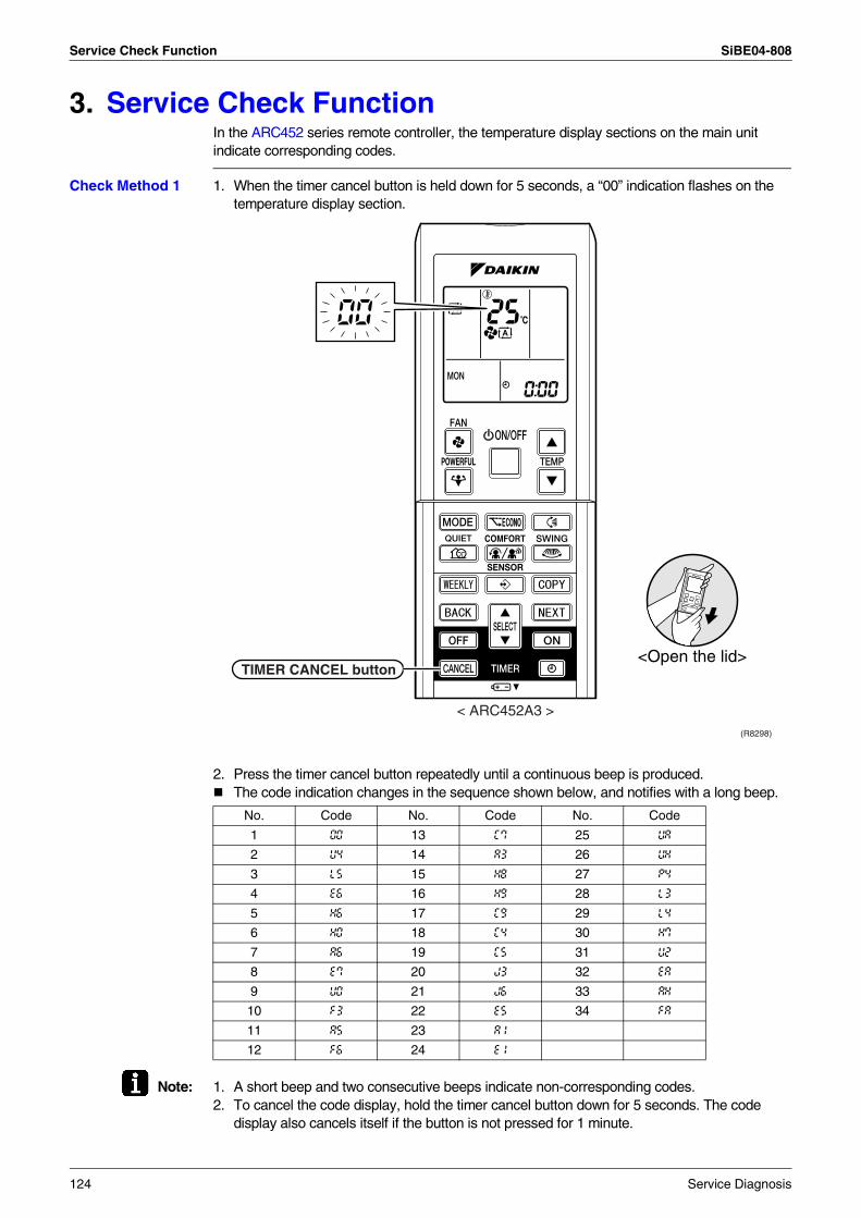
Service Check Function SiBE04-808
3. Service Check FunctionIn the ARC452 series remote controller, the temperature display sections on the main unit indicate corresponding codes.
Check Method 1 1. When the timer cancel button is held down for 5 seconds, a “00” indication flashes on the temperature display section.
2. Press the timer cancel button repeatedly until a continuous beep is produced.The code indication changes in the sequence shown below, and notifies with a long beep.
Note: 1. A short beep and two consecutive beeps indicate non-corresponding codes.2. To cancel the code display, hold the timer cancel button down for 5 seconds. The code
display also cancels itself if the button is not pressed for 1 minute.
No. Code No. Code No. Code
1 00 13 C7 25 UA
2 U4 14 A3 26 UH
3 L5 15 H8 27 P4
4 E6 16 H9 28 L3
5 H6 17 C9 29 L4
6 H0 18 C4 30 H7
7 A6 19 C5 31 U2
8 E7 20 J3 32 EA
9 U0 21 J6 33 AH
10 F3 22 E5 34 FA
11 A5 23 A1
12 F6 24 E1
< ARC452A3 >
(R8298)
TIMER CANCEL button<Open the lid>
124 Service Diagnosis
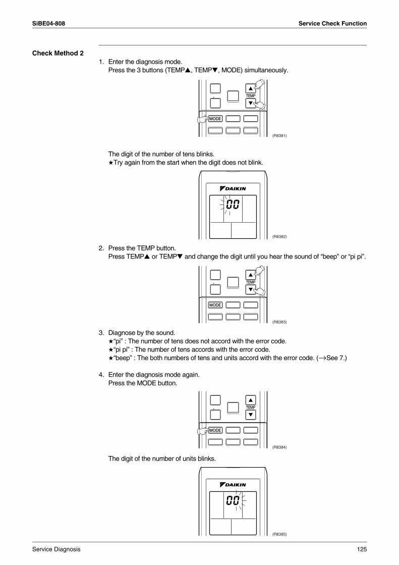
SiBE04-808 Service Check Function
Check Method 21. Enter the diagnosis mode.
Press the 3 buttons (TEMP, TEMP, MODE) simultaneously.
The digit of the number of tens blinks.Try again from the start when the digit does not blink.
2. Press the TEMP button.Press TEMP or TEMP and change the digit until you hear the sound of “beep” or “pi pi”.
3. Diagnose by the sound.“pi” : The number of tens does not accord with the error code.“pi pi” : The number of tens accords with the error code.“beep” : The both numbers of tens and units accord with the error code. (→See 7.)
4. Enter the diagnosis mode again.Press the MODE button.
The digit of the number of units blinks.
(R8381)
(R8382)
(R8383)
(R8384)
(R8385)
Service Diagnosis 125
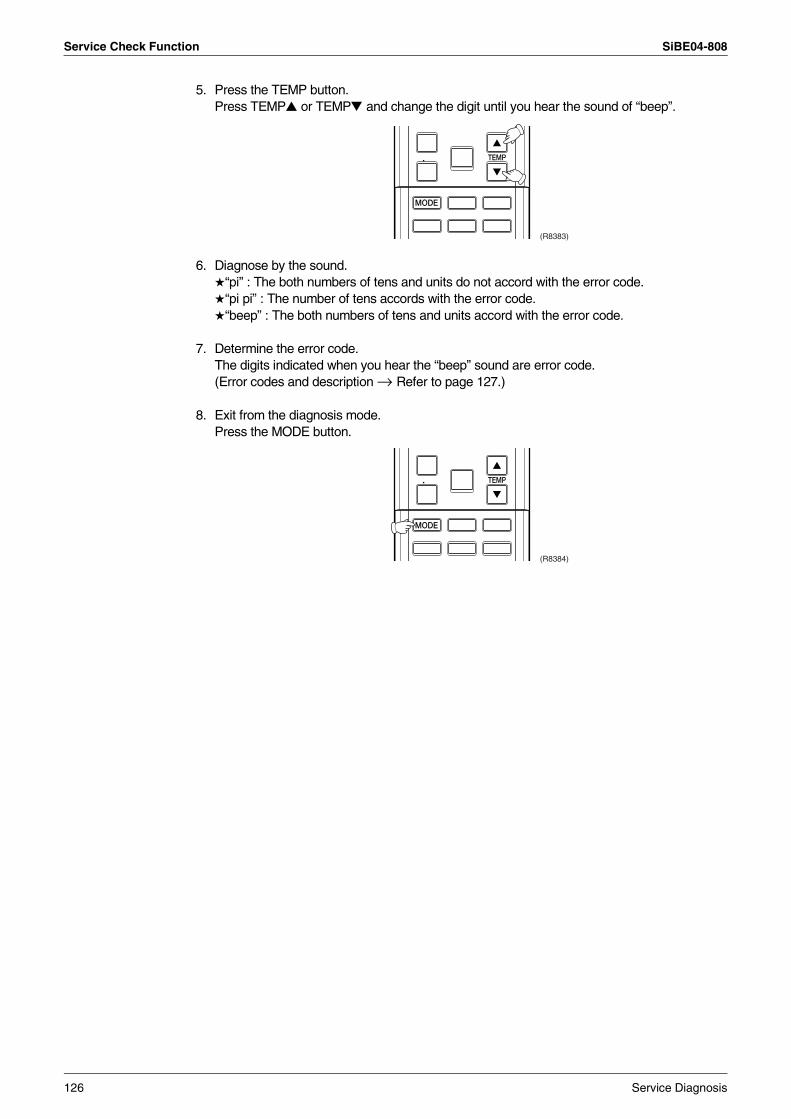
Service Check Function SiBE04-808
5. Press the TEMP button.Press TEMP or TEMP and change the digit until you hear the sound of “beep”.
6. Diagnose by the sound.“pi” : The both numbers of tens and units do not accord with the error code.“pi pi” : The number of tens accords with the error code.“beep” : The both numbers of tens and units accord with the error code.
7. Determine the error code.The digits indicated when you hear the “beep” sound are error code.(Error codes and description → Refer to page 127.)
8. Exit from the diagnosis mode.Press the MODE button.
(R8383)
(R8384)
126 Service Diagnosis
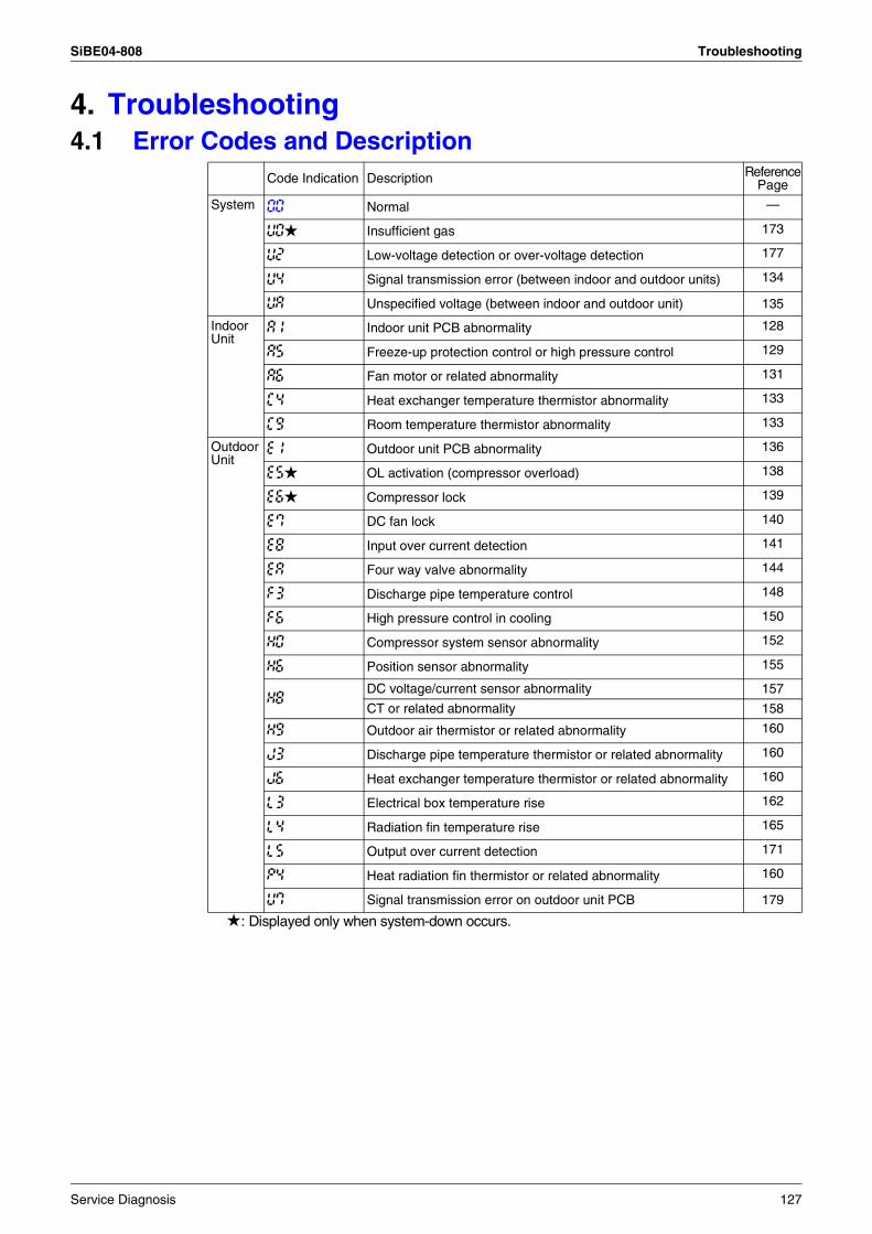
SiBE04-808 Troubleshooting
4. Troubleshooting4.1 Error Codes and Description
: Displayed only when system-down occurs.
Code Indication Description ReferencePage
System 00 Normal —
U0 Insufficient gas 173
U2 Low-voltage detection or over-voltage detection 177
U4 Signal transmission error (between indoor and outdoor units) 134
UA Unspecified voltage (between indoor and outdoor unit) 135
IndoorUnit
A1 Indoor unit PCB abnormality 128
A5 Freeze-up protection control or high pressure control 129
A6 Fan motor or related abnormality 131
C4 Heat exchanger temperature thermistor abnormality 133
C9 Room temperature thermistor abnormality 133
OutdoorUnit
E1 Outdoor unit PCB abnormality 136
E5 OL activation (compressor overload) 138
E6 Compressor lock 139
E7 DC fan lock 140
E8 Input over current detection 141
EA Four way valve abnormality 144
F3 Discharge pipe temperature control 148
F6 High pressure control in cooling 150
H0 Compressor system sensor abnormality 152
H6 Position sensor abnormality 155
H8DC voltage/current sensor abnormality 157
CT or related abnormality 158
H9 Outdoor air thermistor or related abnormality 160
J3 Discharge pipe temperature thermistor or related abnormality 160
J6 Heat exchanger temperature thermistor or related abnormality 160
L3 Electrical box temperature rise 162
L4 Radiation fin temperature rise 165
L5 Output over current detection 171
P4 Heat radiation fin thermistor or related abnormality 160
U7 Signal transmission error on outdoor unit PCB 179
Service Diagnosis 127
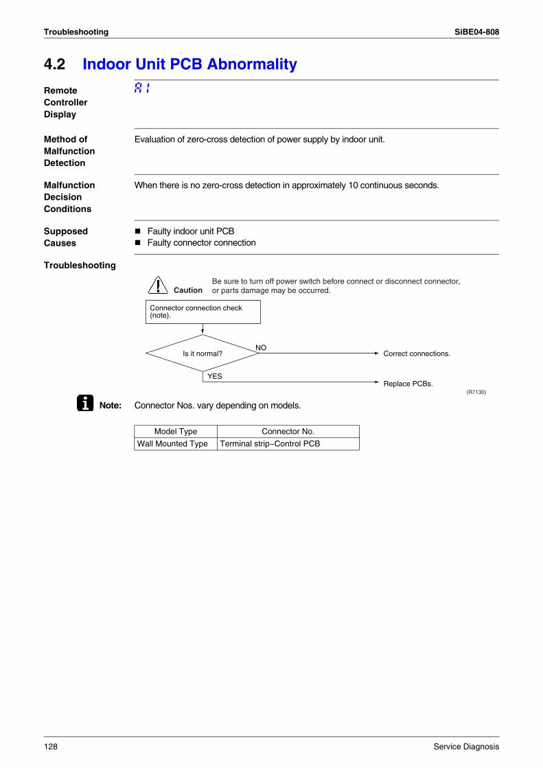
Troubleshooting SiBE04-808
4.2 Indoor Unit PCB Abnormality
Remote Controller Display
A1
Method of Malfunction Detection
Evaluation of zero-cross detection of power supply by indoor unit.
Malfunction Decision Conditions
When there is no zero-cross detection in approximately 10 continuous seconds.
Supposed Causes
Faulty indoor unit PCBFaulty connector connection
Troubleshooting
Note: Connector Nos. vary depending on models.
Connector connection check (note).
Is it normal?
YES
NO
(R7130)
CautionBe sure to turn off power switch before connect or disconnect connector, or parts damage may be occurred.
Correct connections.
Replace PCBs.
Model Type Connector No.
Wall Mounted Type Terminal strip~Control PCB
128 Service Diagnosis
SiBE04-808 Troubleshooting
4.3 Freeze-up Protection Control or High Pressure Control
Remote Controller Display
A5
Method of Malfunction Detection
High pressure control (heat pump model only)During heating operations, the temperature detected by the indoor heat exchanger thermistor is used for the high pressure control (stop, outdoor fan stop, etc.) Freeze-up protection control (operation halt) is activated during cooling operation according to the temperature detected by the indoor unit heat exchanger thermistor.
Malfunction Decision Conditions
High pressure controlDuring heating operations, the temperature detected by the indoor heat exchanger thermistor is above 65°CFreeze-up protection
When the indoor unit heat exchanger temperature is below 0°C during cooling operation.
Supposed Causes
Operation halt due to clogged air filter of the indoor unit.Operation halt due to dust accumulation on the indoor unit heat exchanger.Operation halt due to short-circuit.Detection error due to faulty indoor unit heat exchanger thermistor.Detection error due to faulty indoor unit PCB.
Service Diagnosis 129
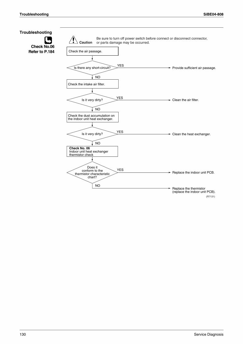
Troubleshooting SiBE04-808
Troubleshooting
Check No.06Refer to P.184
NO
NO
NO
Check No. 06Indoor unit heat exchanger thermistor check
YES
YES
(R7131)
YES
YES
NO
CautionBe sure to turn off power switch before connect or disconnect connector, or parts damage may be occurred.
Provide sufficient air passage.
Clean the air filter.
Clean the heat exchanger.
Replace the indoor unit PCB.
Replace the thermistor (replace the indoor unit PCB).
Does it conform to the
thermistor characteristic chart?
Check the intake air filter.
Check the dust accumulation on the indoor unit heat exchanger.
Is there any short-circuit?
Is it very dirty?
Is it very dirty?
Check the air passage.
130 Service Diagnosis
SiBE04-808 Troubleshooting
4.4 Fan Motor (DC Motor) or Related Abnormality
Remote Controller Display
A6
Method of Malfunction Detection
The rotation speed detected by the Hall IC during fan motor operation is used to determine abnormal fan motor operation.
Malfunction Decision Conditions
When the detected rotation speed does not reach the demanded rotation speed of the target tap, and is less than 50% of the maximum fan motor rotation speed.
Supposed Causes
Operation halt due to short circuit inside the fan motor winding.Operation halt due to breaking of wire inside the fan motor.Operation halt due to breaking of the fan motor lead wires.Operation halt due to faulty capacitor of the fan motor.Detection error due to faulty indoor unit PCB.
Service Diagnosis 131
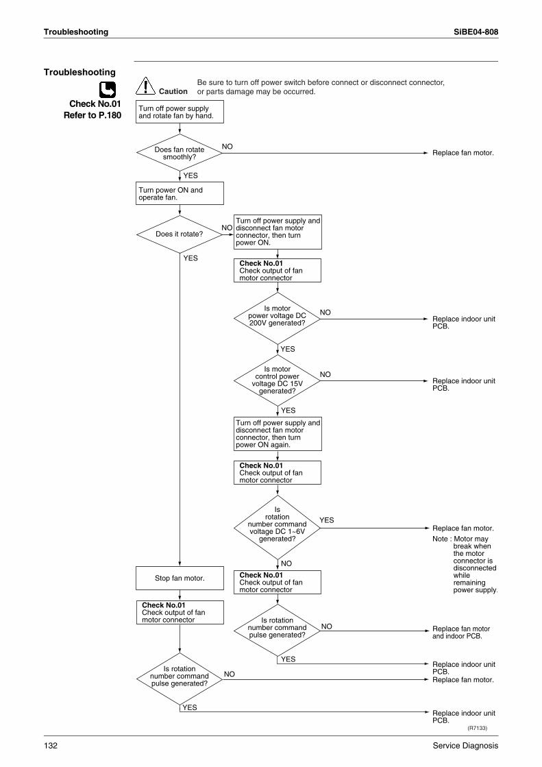
Troubleshooting SiBE04-808
Troubleshooting
Check No.01Refer to P.180
Turn off power supply and disconnect fan motor connector, then turn power ON.
Turn off power supply and disconnect fan motor connector, then turn power ON again.
Check No.01Check output of fan motor connector
Check No.01Check output of fan motor connector
Check No.01Check output of fan motor connector
Check No.01Check output of fan motor connector
(R7133)
YES
YES
NO
YES
YES
NO
YES
NO
NO
YES
NO
YES
NO
NO
CautionBe sure to turn off power switch before connect or disconnect connector, or parts damage may be occurred.
Replace fan motor.
Replace indoor unit PCB.
Replace indoor unit PCB.
Note : Motor may break when the motor connector is disconnected while remaining power supply.
Replace fan motor.
Replace indoor unit PCB.
Replace indoor unit PCB.
Replace fan motor.
Replace fan motor and indoor PCB.
Does fan rotate smoothly?
Does it rotate?
Is rotation number command pulse generated?
Is motor power voltage DC 200V generated?
Is motor control power
voltage DC 15V generated?
Is rotation
number command voltage DC 1~6V
generated?
Is rotation number command pulse generated?
Turn off power supply and rotate fan by hand.
Turn power ON and operate fan.
Stop fan motor.
132 Service Diagnosis
SiBE04-808 Troubleshooting
4.5 Thermistor or Related Abnormality (Indoor Unit)
Remote Controller Display
C4, C9
Method of Malfunction Detection
The temperatures detected by the thermistors are used to determine thermistor errors.
Malfunction Decision Conditions
When the thermistor input is more than 4.96 V or less than 0.04 V during compressor operation∗.∗ (reference)When above about 212°C (less than 120 ohms) or below about -50°C (more than 1,860 kohms).
Note: The values vary slightly in some models.
Supposed Causes
Faulty connector connectionFaulty thermistorFaulty PCB
Troubleshooting
Check No.06Refer to P.184
C4 : Heat exchanger thermistorC9 : Room temperature thermistor
YES
(R7134)
NO
Check No. 06Check the thermistor resistance value.
YES
NO
CautionBe sure to turn off power switch before connect or disconnect connector, or parts damage may be occurred.
Correct the connection.
Replace the thermistor. (Replace the indoor unit PCB.)
Replace the indoor unit PCB.
Is it normal?
Is it normal?
Check the connector connection.
Service Diagnosis 133
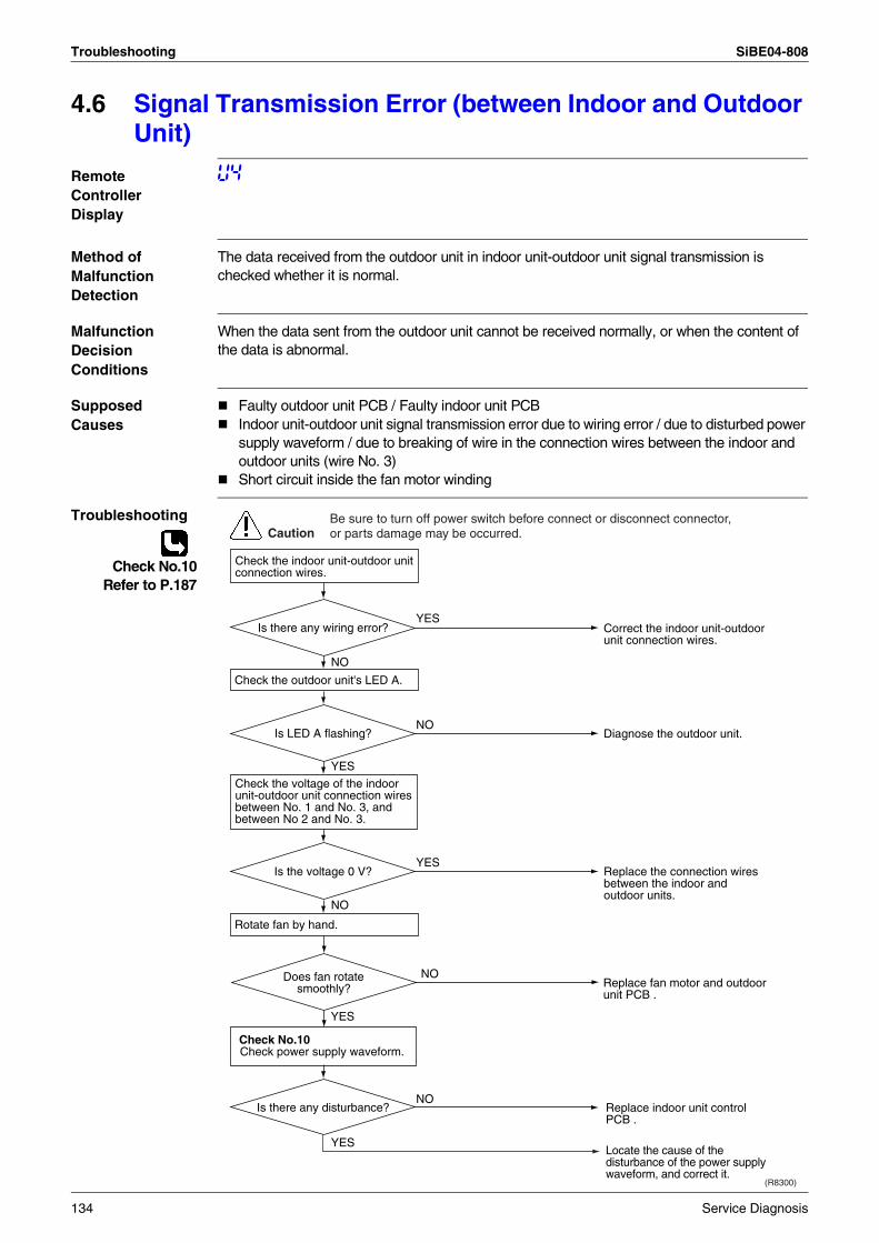
Troubleshooting SiBE04-808
4.6 Signal Transmission Error (between Indoor and Outdoor Unit)
Remote Controller Display
U4
Method of Malfunction Detection
The data received from the outdoor unit in indoor unit-outdoor unit signal transmission is checked whether it is normal.
Malfunction Decision Conditions
When the data sent from the outdoor unit cannot be received normally, or when the content of the data is abnormal.
Supposed Causes
Faulty outdoor unit PCB / Faulty indoor unit PCBIndoor unit-outdoor unit signal transmission error due to wiring error / due to disturbed power supply waveform / due to breaking of wire in the connection wires between the indoor and outdoor units (wire No. 3)Short circuit inside the fan motor winding
Troubleshooting
Check No.10Refer to P.187
Check the voltage of the indoor unit-outdoor unit connection wires between No. 1 and No. 3, and between No 2 and No. 3.
Check No.10Check power supply waveform.
YES
YES
Replace indoor unit control PCB .
Locate the cause of the disturbance of the power supply waveform, and correct it.
NO
(R8300)
NO
YES
YES
NO
NO
CautionBe sure to turn off power switch before connect or disconnect connector, or parts damage may be occurred.
YES
NO
Correct the indoor unit-outdoor unit connection wires.
Diagnose the outdoor unit.
Replace the connection wires between the indoor and outdoor units.
Replace fan motor and outdoor unit PCB .
Does fan rotate smoothly?
Is LED A flashing?
Is the voltage 0 V?
Is there any disturbance?
Is there any wiring error?
Check the indoor unit-outdoor unit connection wires.
Check the outdoor unit's LED A.
Rotate fan by hand.
134 Service Diagnosis
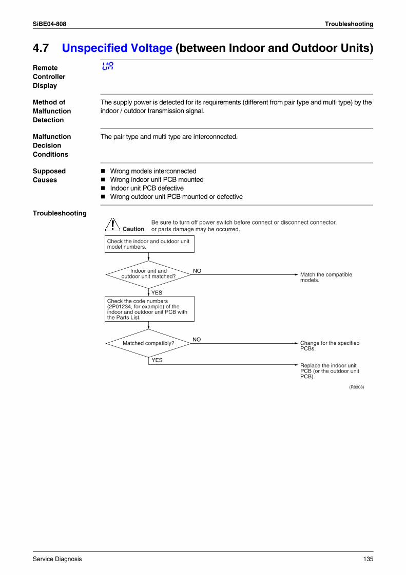
SiBE04-808 Troubleshooting
4.7 Unspecified Voltage (between Indoor and Outdoor Units)
Remote Controller Display
UA
Method of Malfunction Detection
The supply power is detected for its requirements (different from pair type and multi type) by the indoor / outdoor transmission signal.
Malfunction Decision Conditions
The pair type and multi type are interconnected.
Supposed Causes
Wrong models interconnectedWrong indoor unit PCB mountedIndoor unit PCB defectiveWrong outdoor unit PCB mounted or defective
Troubleshooting
CautionBe sure to turn off power switch before connect or disconnect connector, or parts damage may be occurred.
Check the indoor and outdoor unit model numbers.
(R8308)
YES
NO
NO
YES
Check the code numbers (2P01234, for example) of the indoor and outdoor unit PCB with the Parts List.
Match the compatible models.
Replace the indoor unit PCB (or the outdoor unit PCB).
Change for the specified PCBs.
Matched compatibly?
Indoor unit and outdoor unit matched?
Service Diagnosis 135
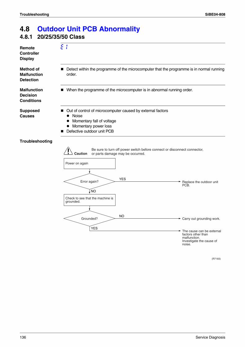
Troubleshooting SiBE04-808
4.8 Outdoor Unit PCB Abnormality4.8.1 20/25/35/50 Class
Remote Controller Display
E1
Method of Malfunction Detection
Detect within the programme of the microcomputer that the programme is in normal running order.
Malfunction Decision Conditions
When the programme of the microcomputer is in abnormal running order.
Supposed Causes
Out of control of microcomputer caused by external factors NoiseMomentary fall of voltageMomentary power loss
Defective outdoor unit PCB
Troubleshooting
(R7183)
CautionBe sure to turn off power switch before connect or disconnect connector, or parts damage may be occurred.
YES
NO
NO
YES
Power on again
Check to see that the machine is grounded.
Replace the outdoor unit PCB.
Carry out grounding work.
The cause can be external factors other than malfunction.Investigate the cause of noise.
Error again?
Grounded?
136 Service Diagnosis
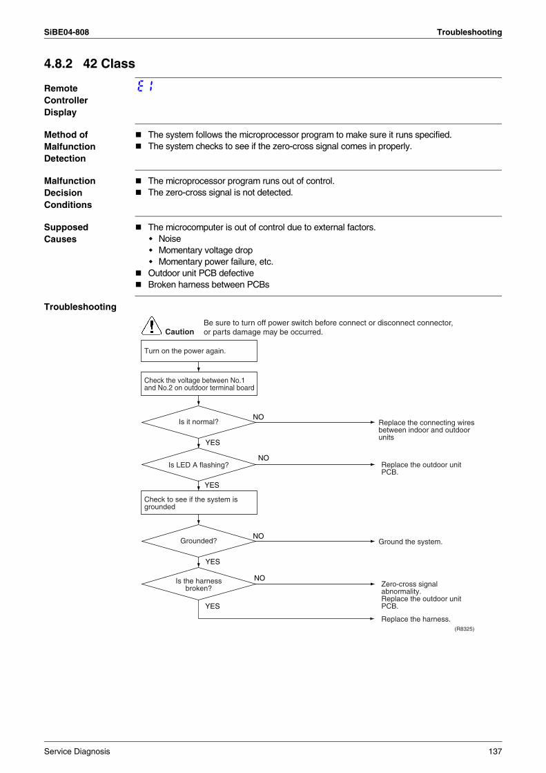
SiBE04-808 Troubleshooting
4.8.2 42 Class
Remote Controller Display
E1
Method of Malfunction Detection
The system follows the microprocessor program to make sure it runs specified.The system checks to see if the zero-cross signal comes in properly.
Malfunction Decision Conditions
The microprocessor program runs out of control.The zero-cross signal is not detected.
Supposed Causes
The microcomputer is out of control due to external factors.NoiseMomentary voltage dropMomentary power failure, etc.
Outdoor unit PCB defectiveBroken harness between PCBs
Troubleshooting
CautionBe sure to turn off power switch before connect or disconnect connector, or parts damage may be occurred.
NO
YES
YES
YES
NO
(R8325)
NO
YES
Replace the outdoor unit PCB.
Ground the system.
Zero-cross signal abnormality.Replace the outdoor unit PCB.
Replace the harness.
Check to see if the system is grounded
Is LED A flashing?
Grounded?
NOReplace the connecting wires between indoor and outdoor units
Check the voltage between No.1 and No.2 on outdoor terminal board
Is it normal?
Is the harness broken?
Turn on the power again.
Service Diagnosis 137
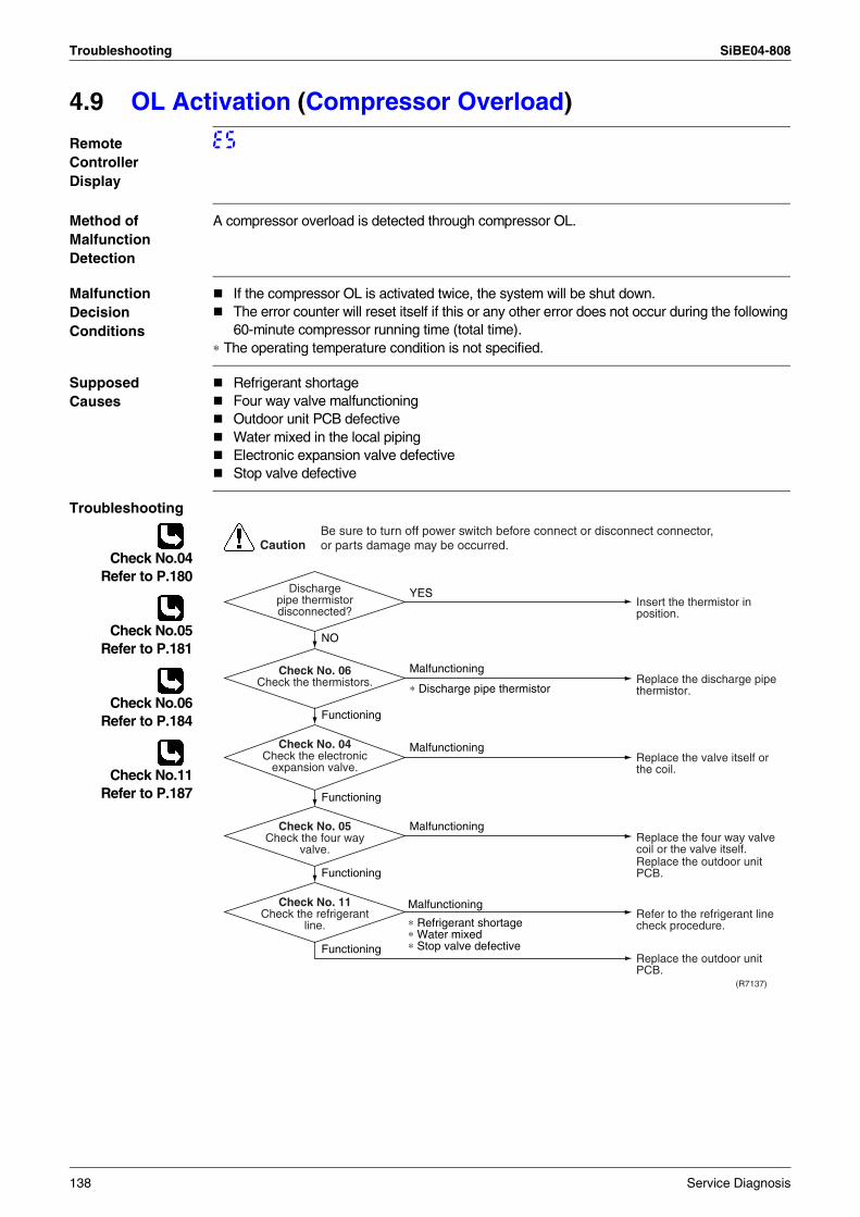
Troubleshooting SiBE04-808
4.9 OL Activation (Compressor Overload)
Remote Controller Display
E5
Method of Malfunction Detection
A compressor overload is detected through compressor OL.
Malfunction Decision Conditions
If the compressor OL is activated twice, the system will be shut down.The error counter will reset itself if this or any other error does not occur during the following 60-minute compressor running time (total time).
∗ The operating temperature condition is not specified.
Supposed Causes
Refrigerant shortageFour way valve malfunctioningOutdoor unit PCB defectiveWater mixed in the local pipingElectronic expansion valve defectiveStop valve defective
Troubleshooting
Check No.04Refer to P.180
Check No.05Refer to P.181
Check No.06Refer to P.184
Check No.11Refer to P.187
(R7137)
CautionBe sure to turn off power switch before connect or disconnect connector, or parts damage may be occurred.
YES
Malfunctioning
∗ Discharge pipe thermistor
NO
Functioning
Functioning
Malfunctioning
∗ Refrigerant shortage∗ Water mixed∗ Stop valve defective
Malfunctioning
Functioning
Malfunctioning
Functioning
Insert the thermistor in position.
Replace the discharge pipe thermistor.
Replace the valve itself or the coil.
Refer to the refrigerant line check procedure.
Replace the outdoor unit PCB.
Replace the four way valve coil or the valve itself.Replace the outdoor unit PCB.
Discharge pipe thermistor disconnected?
Check No. 06Check the thermistors.
Check No. 05Check the four way
valve.
Check No. 11Check the refrigerant
line.
Check No. 04Check the electronic
expansion valve.
138 Service Diagnosis
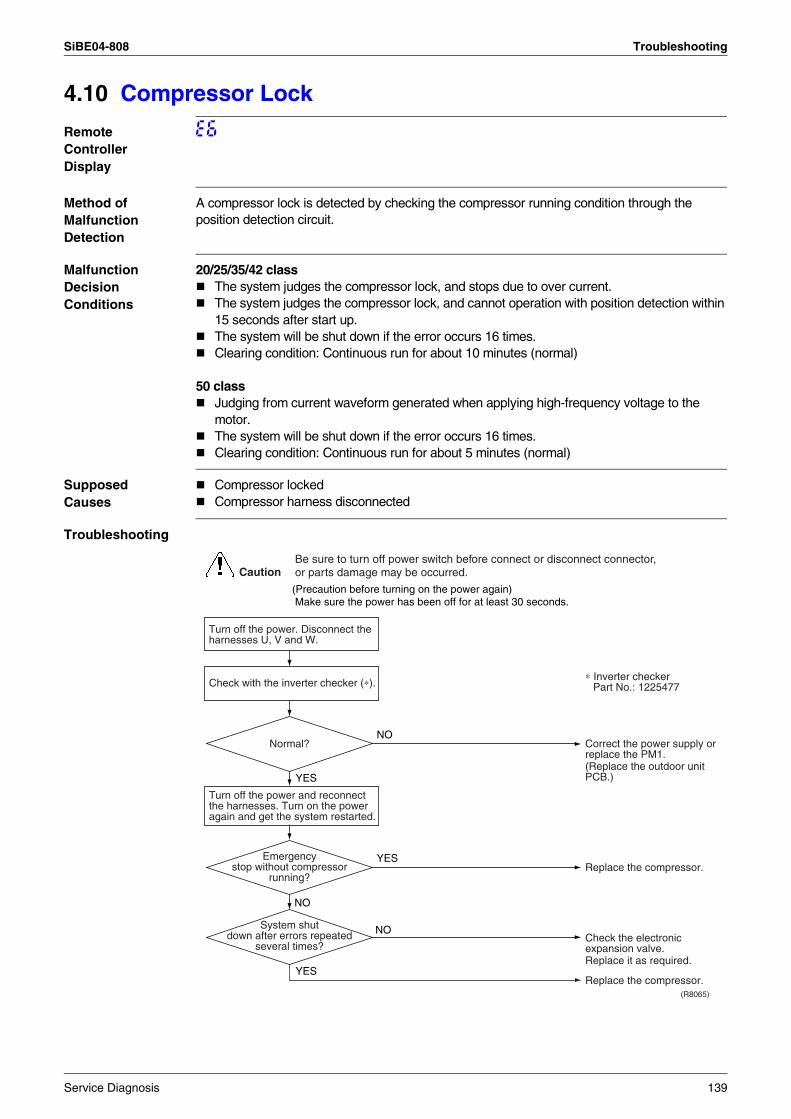
SiBE04-808 Troubleshooting
4.10 Compressor Lock
Remote Controller Display
E6
Method of Malfunction Detection
A compressor lock is detected by checking the compressor running condition through the position detection circuit.
Malfunction Decision Conditions
20/25/35/42 classThe system judges the compressor lock, and stops due to over current.The system judges the compressor lock, and cannot operation with position detection within 15 seconds after start up.The system will be shut down if the error occurs 16 times.Clearing condition: Continuous run for about 10 minutes (normal)
50 classJudging from current waveform generated when applying high-frequency voltage to the motor.The system will be shut down if the error occurs 16 times.Clearing condition: Continuous run for about 5 minutes (normal)
Supposed Causes
Compressor lockedCompressor harness disconnected
Troubleshooting
Turn off the power. Disconnect the harnesses U, V and W.
(R8065)
CautionBe sure to turn off power switch before connect or disconnect connector, or parts damage may be occurred.
NO
YES
YES
NO
NO
YES
Check with the inverter checker (∗).
Turn off the power and reconnect the harnesses. Turn on the power again and get the system restarted.
(Precaution before turning on the power again) Make sure the power has been off for at least 30 seconds.
Correct the power supply or replace the PM1.(Replace the outdoor unit PCB.)
∗ Inverter checkerPart No.: 1225477
Replace the compressor.
Replace it as required.
Replace the compressor.
Check the electronic expansion valve.
Normal?
Emergency stop without compressor
running?
System shut down after errors repeated
several times?
Service Diagnosis 139
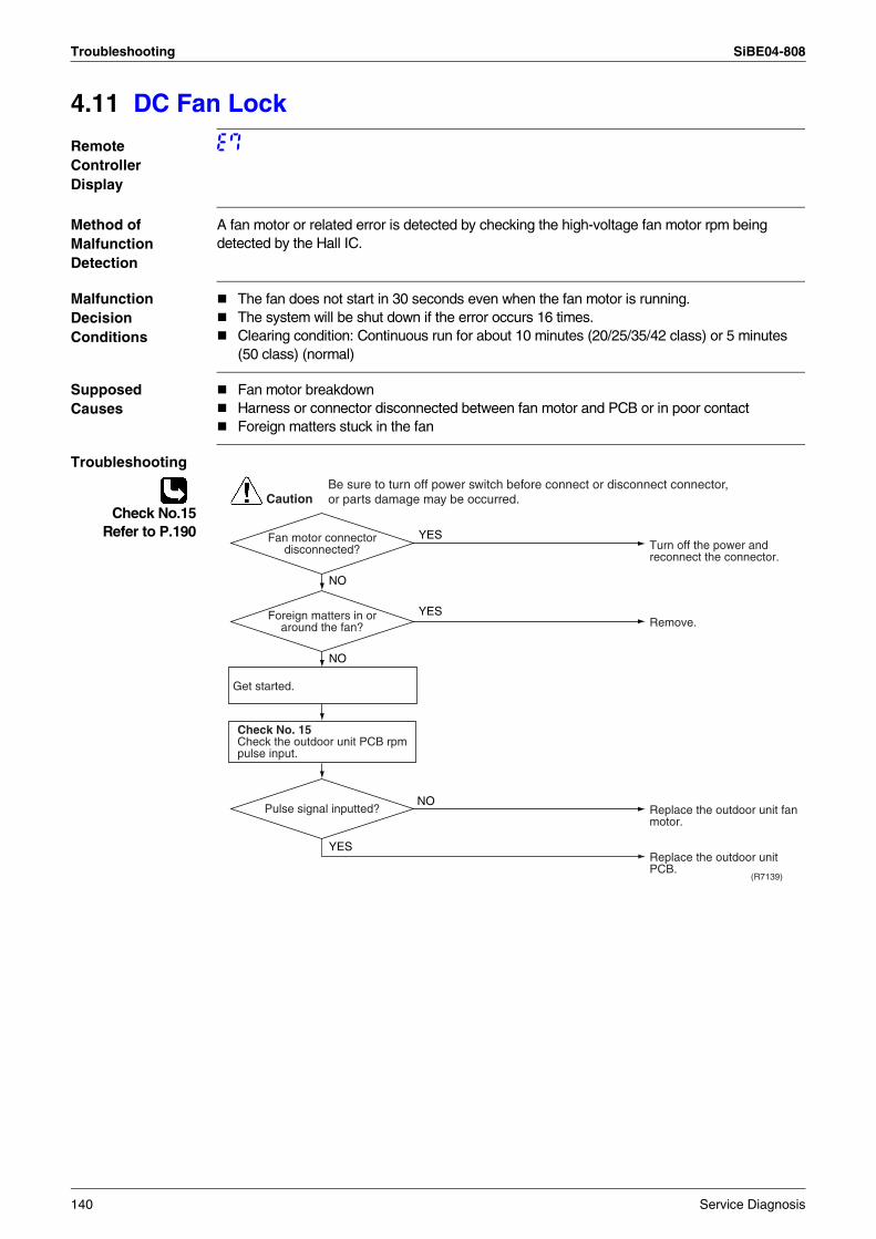
Troubleshooting SiBE04-808
4.11 DC Fan Lock
Remote Controller Display
E7
Method of Malfunction Detection
A fan motor or related error is detected by checking the high-voltage fan motor rpm being detected by the Hall IC.
Malfunction Decision Conditions
The fan does not start in 30 seconds even when the fan motor is running.The system will be shut down if the error occurs 16 times.Clearing condition: Continuous run for about 10 minutes (20/25/35/42 class) or 5 minutes (50 class) (normal)
Supposed Causes
Fan motor breakdownHarness or connector disconnected between fan motor and PCB or in poor contactForeign matters stuck in the fan
Troubleshooting
Check No.15Refer to P.190
(R7139)
CautionBe sure to turn off power switch before connect or disconnect connector, or parts damage may be occurred.
YES
YES
NO
YES
NO
NO
Get started.
Check No. 15Check the outdoor unit PCB rpm pulse input.
Turn off the power and reconnect the connector.
Remove.
Replace the outdoor unit fan motor.
Replace the outdoor unit PCB.
Fan motor connector disconnected?
Foreign matters in or around the fan?
Pulse signal inputted?
140 Service Diagnosis
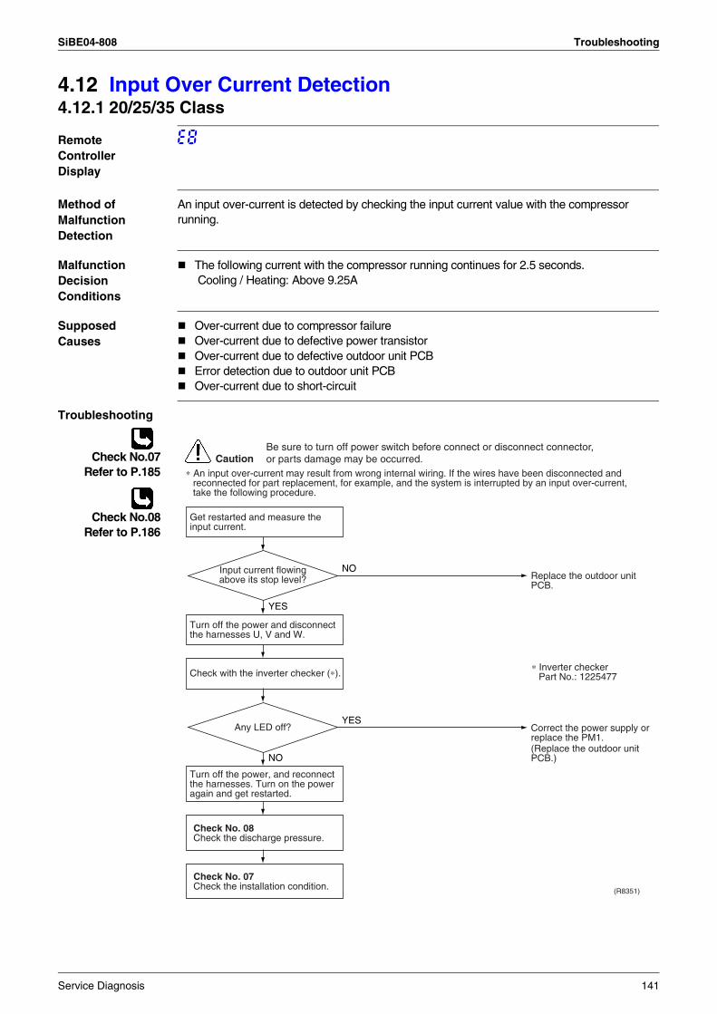
SiBE04-808 Troubleshooting
4.12 Input Over Current Detection4.12.1 20/25/35 Class
Remote Controller Display
E8
Method of Malfunction Detection
An input over-current is detected by checking the input current value with the compressor running.
Malfunction Decision Conditions
The following current with the compressor running continues for 2.5 seconds. Cooling / Heating: Above 9.25A
Supposed Causes
Over-current due to compressor failureOver-current due to defective power transistorOver-current due to defective outdoor unit PCBError detection due to outdoor unit PCBOver-current due to short-circuit
Troubleshooting
Check No.07Refer to P.185
Check No.08Refer to P.186
CautionBe sure to turn off power switch before connect or disconnect connector, or parts damage may be occurred.
∗ An input over-current may result from wrong internal wiring. If the wires have been disconnected and reconnected for part replacement, for example, and the system is interrupted by an input over-current, take the following procedure.
(R8351)
NO
YES
YES
NO
Get restarted and measure the input current.
Check No. 08Check the discharge pressure.
Check No. 07Check the installation condition.
Check with the inverter checker (∗).
Turn off the power and disconnect the harnesses U, V and W.
Turn off the power, and reconnect the harnesses. Turn on the power again and get restarted.
Replace the outdoor unit PCB.
Correct the power supply or replace the PM1.(Replace the outdoor unit PCB.)
Any LED off?
Input current flowing above its stop level?
∗ Inverter checkerPart No.: 1225477
Service Diagnosis 141
Troubleshooting SiBE04-808
4.12.2 42/50 Class
Remote Controller Display
E8
Method of Malfunction Detection
42 classAn input over-current is detected by checking the input current value with the compressor running.
50 classAn input over-current is detected by checking the input current value being detected by CT with the compressor running.
Malfunction Decision Conditions
The following current with the compressor running continues for 2.5 seconds. Cooling / Heating : Above 15A (42 class)The following CT input with the compressor running continues for 2.5 seconds. CT input : Above 20 A (50 class)The system will be shut down if the error occurs 16 times. (50 class)Clearing condition : Continuous run for about 5 minutes (normal) (50 class)
Supposed Causes
Over-current due to compressor failureOver-current due to defective power transistorOver-current due to defective inverter main circuit electrolytic capacitor (50 class only)Over-current due to defective outdoor unit PCBError detection due to outdoor unit PCBOver-current due to short-circuit
142 Service Diagnosis
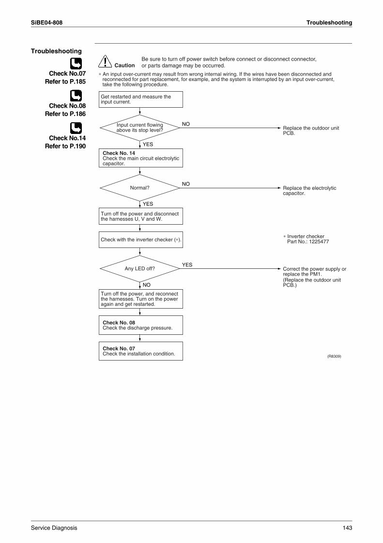
SiBE04-808 Troubleshooting
Troubleshooting
Check No.07Refer to P.185
Check No.08Refer to P.186
Check No.14Refer to P.190
(R8309)
CautionBe sure to turn off power switch before connect or disconnect connector, or parts damage may be occurred.
∗ An input over-current may result from wrong internal wiring. If the wires have been disconnected and reconnected for part replacement, for example, and the system is interrupted by an input over-current, take the following procedure.
NO
YES
NO
YES
YES
NO
Get restarted and measure the input current.
Check No. 14Check the main circuit electrolytic capacitor.
Check No. 08Check the discharge pressure.
Check No. 07Check the installation condition.
Check with the inverter checker (∗).
Turn off the power and disconnect the harnesses U, V and W.
Turn off the power, and reconnect the harnesses. Turn on the power again and get restarted.
Replace the outdoor unit PCB.
Replace the electrolytic capacitor.
Correct the power supply or replace the PM1.(Replace the outdoor unit PCB.)
Normal?
Any LED off?
Input current flowing above its stop level?
∗ Inverter checkerPart No.: 1225477
Service Diagnosis 143
Troubleshooting SiBE04-808
4.13 Four Way Valve Abnormality4.13.1 20/25/35/42 Class
Remote Controller Display
EA
Method of Malfunction Detection
The indoor air temperature thermistor, the indoor unit heat exchanger thermistor, the outdoor temperature thermistor and the outdoor unit heat exchanger thermistor are checked to see if they function within their normal ranges in the operating mode.
Malfunction Decision Conditions
A following condition continues over 10 minute after operating 5 minutes.Cooling / dry operation(room temp. – indoor heat exchanger temp.) < –5°CHeating(indoor unit heat exchanger temp. – room temp.) < –5°C
Supposed Causes
Connector in poor contactThermistor defectiveOutdoor unit PCB defectiveFour way valve coil or harness defectiveFour way valve defectiveForeign substance mixed in refrigerantInsufficient gas
144 Service Diagnosis
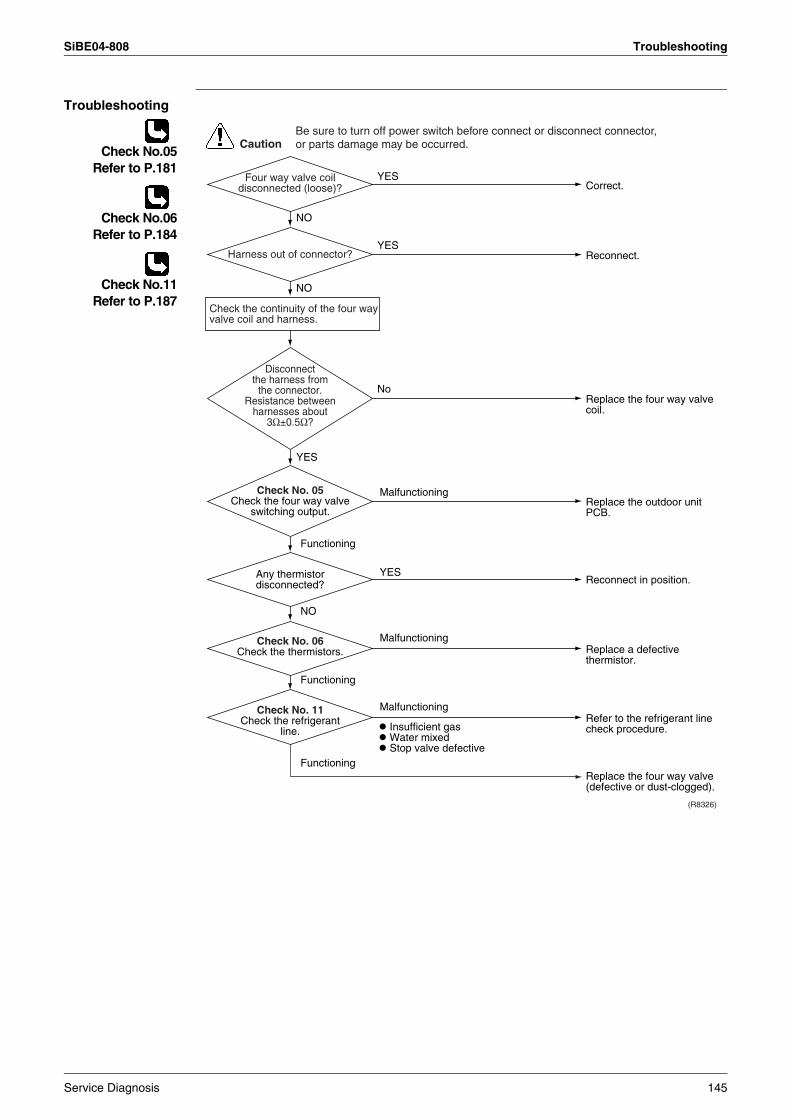
SiBE04-808 Troubleshooting
Troubleshooting
Check No.05Refer to P.181
Check No.06Refer to P.184
Check No.11Refer to P.187
Malfunctioning
Functioning
NO
Functioning
Malfunctioning
Functioning
YES
Malfunctioning
Correct.
Reconnect.
YES
YES
YES
NO
NO
Replace the four way valve coil.
No
Replace the outdoor unit PCB.
Insufficient gas Water mixed Stop valve defective
Replace a defective thermistor.
Refer to the refrigerant line check procedure.
Replace the four way valve (defective or dust-clogged).
Reconnect in position.
CautionBe sure to turn off power switch before connect or disconnect connector, or parts damage may be occurred.
(R8326)
Four way valve coil disconnected (loose)?
Harness out of connector?
Any thermistor disconnected?
Check No. 06Check the thermistors.
Check No. 11Check the refrigerant
line.
Check No. 05Check the four way valve
switching output.
Disconnect the harness from
the connector.Resistance between
harnesses about 3Ω±0.5Ω?
Check the continuity of the four way valve coil and harness.
Service Diagnosis 145
Troubleshooting SiBE04-808
4.13.2 50 Class
Remote Controller Display
EA
Method of Malfunction Detection
The room temperature thermistor, the indoor unit heat exchanger thermistor, the outdoor temperature thermistor and the outdoor unit heat exchanger thermistor are checked to see if they function within their normal ranges in the operating mode.
Malfunction Decision Conditions
A following condition continues over 1 minute after operating 10 minutes.Cooling / dry operation(room temp. – indoor heat exchanger temp.) < –5°CHeating(indoor unit heat exchanger temp. – room temp.) < –5°CThe system will be shut down if the cooling / heating changeover abnormality occurs 5 times.
Supposed Causes
Connector in poor contactThermistor defectiveOutdoor unit PCB defectiveFour way valve coil or harness defectiveFour way valve defectiveForeign substance mixed in refrigerantInsufficient gas
146 Service Diagnosis
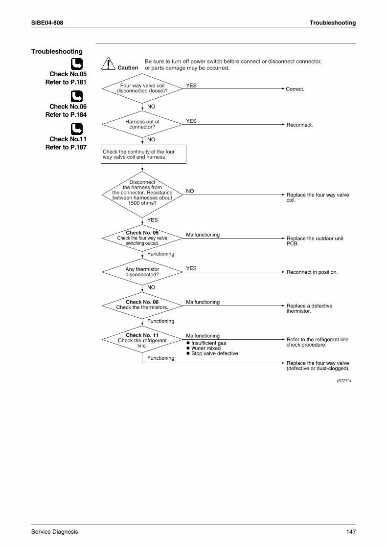
SiBE04-808 Troubleshooting
Troubleshooting
Check No.05Refer to P.181
Check No.06Refer to P.184
Check No.11Refer to P.187
(R7272)
CautionBe sure to turn off power switch before connect or disconnect connector, or parts damage may be occurred.
Reconnect.
Replace the four way valve (defective or dust-clogged).
Replace the four way valve coil.
Replace the outdoor unit PCB.
Reconnect in position.
Replace a defective thermistor.
Refer to the refrigerant line check procedure.
Correct.
Check the continuity of the four way valve coil and harness.
Check No. 05Check the four way valve
switching output.
Any thermistor disconnected?
Check No. 06Check the thermistors.
Check No. 11Check the refrigerant
line.
Disconnect the harness from
the connector. Resistance between harnesses about
1500 ohms?
Harness out of connector?
Four way valve coil disconnected (loose)?
YES
Functioning
YES
NO
NO
NO
Functioning
Malfunctioning
NO
YES
Functioning
Malfunctioning
Malfunctioning Insufficient gas Water mixed Stop valve defective
YES
Service Diagnosis 147
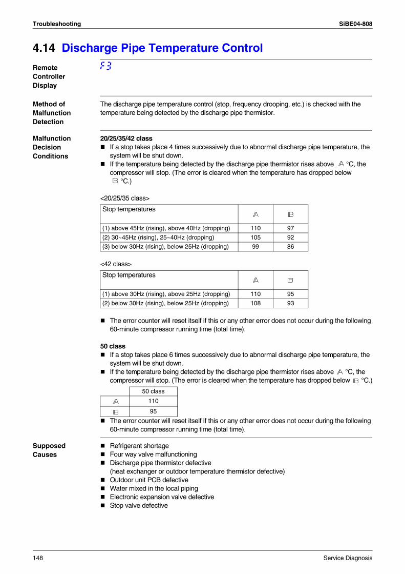
Troubleshooting SiBE04-808
4.14 Discharge Pipe Temperature Control
Remote Controller Display
F3
Method of Malfunction Detection
The discharge pipe temperature control (stop, frequency drooping, etc.) is checked with the temperature being detected by the discharge pipe thermistor.
Malfunction Decision Conditions
20/25/35/42 classIf a stop takes place 4 times successively due to abnormal discharge pipe temperature, the system will be shut down.If the temperature being detected by the discharge pipe thermistor rises above °C, the compressor will stop. (The error is cleared when the temperature has dropped below
°C.)
<20/25/35 class>
<42 class>
The error counter will reset itself if this or any other error does not occur during the following 60-minute compressor running time (total time).
50 classIf a stop takes place 6 times successively due to abnormal discharge pipe temperature, the system will be shut down.If the temperature being detected by the discharge pipe thermistor rises above °C, the compressor will stop. (The error is cleared when the temperature has dropped below °C.)
The error counter will reset itself if this or any other error does not occur during the following 60-minute compressor running time (total time).
Supposed Causes
Refrigerant shortageFour way valve malfunctioningDischarge pipe thermistor defective(heat exchanger or outdoor temperature thermistor defective)Outdoor unit PCB defectiveWater mixed in the local pipingElectronic expansion valve defectiveStop valve defective
Stop temperatures
(1) above 45Hz (rising), above 40Hz (dropping) 110 97
(2) 30~45Hz (rising), 25~40Hz (dropping) 105 92
(3) below 30Hz (rising), below 25Hz (dropping) 99 86
Stop temperatures
(1) above 30Hz (rising), above 25Hz (dropping) 110 95
(2) below 30Hz (rising), below 25Hz (dropping) 108 93
50 class
110
95
148 Service Diagnosis
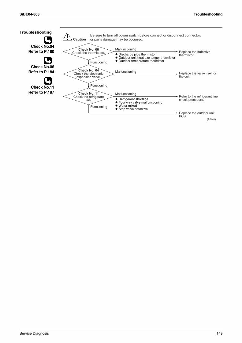
SiBE04-808 Troubleshooting
Troubleshooting
Check No.04Refer to P.180
Check No.06Refer to P.184
Check No.11Refer to P.187
(R7141)
CautionBe sure to turn off power switch before connect or disconnect connector, or parts damage may be occurred.
Malfunctioning
Discharge pipe thermistor Outdoor unit heat exchanger thermistor Outdoor temperature thermistor
Refrigerant shortage Four way valve malfunctioning Water mixed Stop valve defective
Functioning
Functioning
Functioning
Malfunctioning
Malfunctioning
Check No. 06Check the thermistors.
Check No. 11Check the refrigerant
line.
Check No. 04Check the electronic
expansion valve.
Replace the defective thermistor.
Replace the valve itself or the coil.
Refer to the refrigerant line check procedure.
Replace the outdoor unit PCB.
Service Diagnosis 149
Troubleshooting SiBE04-808
4.15 High Pressure Control in Cooling
Remote Controller Display
F6
Method of Malfunction Detection
High-pressure control (stop, frequency drop, etc.) is activated in the cooling mode if the temperature being sensed by the heat exchanger thermistor exceeds the limit.
Malfunction Decision Conditions
Activated when the temperature being sensed by the heat exchanger thermistor rises above 65°C. The error is cleared when the temperature drops below 54°C (20/25/35 class), 53°C (42 class) or 51°C (50 class).
Supposed Causes
The installation space is not large enough.Faulty outdoor unit fanFaulty electronic expansion valveFaulty defrost thermistorFaulty outdoor unit PCBFaulty stop valveDirty heat exchanger
150 Service Diagnosis
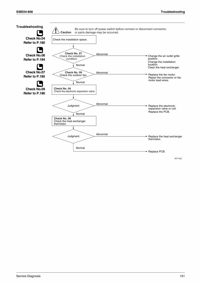
SiBE04-808 Troubleshooting
Troubleshooting
Check No.04Refer to P.180
Check No.06Refer to P.184
Check No.07Refer to P.185
Check No.09Refer to P.186
(R7142)
CautionBe sure to turn off power switch before connect or disconnect connector, or parts damage may be occurred.
Replace the fan motor.Repair the connector or fan motor lead wires.
Replace the heat exchanger thermistor.
Replace PCB.
Replace the electronic expansion valve or coil.Replace the PCB.
Change the air outlet grille position.
Clean the heat exchanger.
Change the installation location.
Check No. 06Check the heat exchanger thermistor.
Check the installation space.
Check No. 04Check the electronic expansion valve.
Abnormal
Normal
Normal
Normal
Normal
Abnormal
Abnormal
Abnormal
Judgment
Judgment
Check No. 09Check the outdoor fan.
Check No. 07Check the installation
condition.
Service Diagnosis 151
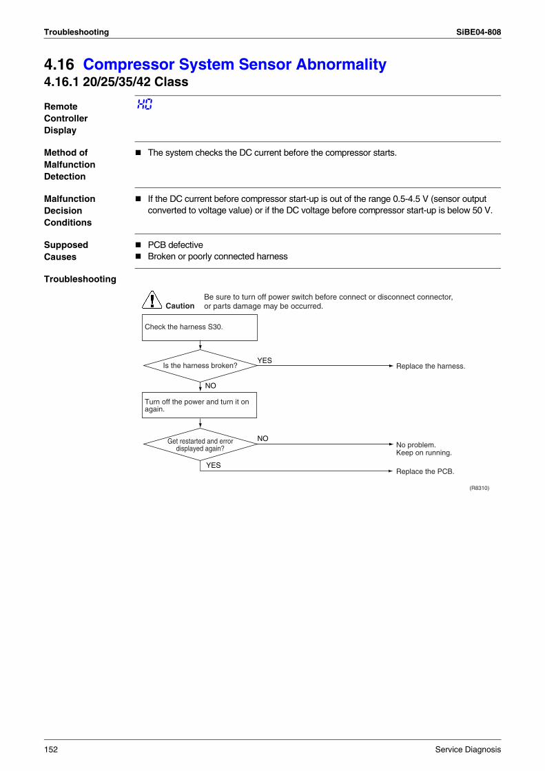
Troubleshooting SiBE04-808
4.16 Compressor System Sensor Abnormality4.16.1 20/25/35/42 Class
Remote Controller Display
H0
Method of Malfunction Detection
The system checks the DC current before the compressor starts.
Malfunction Decision Conditions
If the DC current before compressor start-up is out of the range 0.5-4.5 V (sensor output converted to voltage value) or if the DC voltage before compressor start-up is below 50 V.
Supposed Causes
PCB defectiveBroken or poorly connected harness
Troubleshooting
CautionBe sure to turn off power switch before connect or disconnect connector, or parts damage may be occurred.
NO
(R8310)
YES
Turn off the power and turn it on again.
YES
NO
Replace the harness.
No problem. Keep on running.
Replace the PCB.
Is the harness broken?
Get restarted and error displayed again?
Check the harness S30.
152 Service Diagnosis
SiBE04-808 Troubleshooting
4.16.2 50 Class
Remote Controller Display
H0
Method of Malfunction Detection
Fault condition is identified by the supply voltage and the DC voltage which is detected before the compressor startup.Fault condition is identified by compressor current which is detected right after the compressor startup.
Malfunction Decision Conditions
The detected valve of the supply voltage and the DC voltage is obviously low or high.The compressor current doesn't run when the compressor is started.
Supposed Causes
Reactor disconnectionCompressor disconnectionOutdoor unit PCB defectiveCompressor defective
Service Diagnosis 153
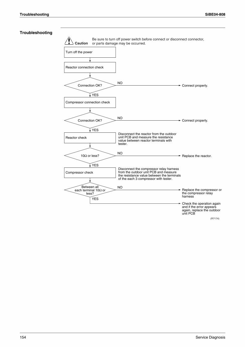
Troubleshooting SiBE04-808
Troubleshooting
Connect properly.
(R7174)
NO
YES
Connect properly.NO
YES
Replace the reactor.NO
YES
Replace the compressor or the compressor relay harness
Check the operation again and if the error appears again, replace the outdoor unit PCB
NO
YES
Disconnect the reactor from the outdoor unit PCB and measure the resistance value between reactor terminals with tester.
Disconnect the compressor relay harness from the outdoor unit PCB and measure the resistance value between the terminals of the each 3 compressor with tester.
CautionBe sure to turn off power switch before connect or disconnect connector, or parts damage may be occurred.
Between all each terminal 10Ω or
less?
Compressor connection check
Reactor check
Compressor check
Turn off the power
Reactor connection check
Connection OK?
Connection OK?
10Ω or less?
154 Service Diagnosis
SiBE04-808 Troubleshooting
4.17 Position Sensor Abnormality
Remote Controller Display
H6
Method of Malfunction Detection
A compressor startup failure is detected by checking the compressor running condition through the position detection circuit.
Malfunction Decision Conditions
The compressor fails to start in about 15 seconds after the compressor run command signal is sent.Clearing condition: Continuous run for about 10 minutes (20/25/35/42 class) or 5 minutes (50 class).The system will be shut down if the error occurs 16 times (20/25/35/42 class) or 8 times (50 class).
Supposed Causes
Compressor relay cable disconnectedCompressor itself defectiveOutdoor unit PCB defectiveStop valve closedInput voltage out of specification
Service Diagnosis 155
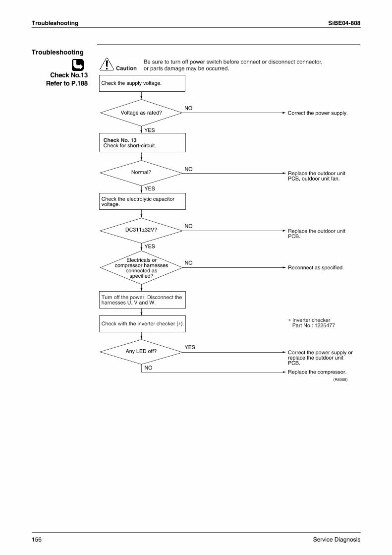
Troubleshooting SiBE04-808
Troubleshooting
Check No.13Refer to P.188
CautionBe sure to turn off power switch before connect or disconnect connector, or parts damage may be occurred.
(R8068)
NO
NO
NO
YES
YES
NO
YES
Check No. 13Check for short-circuit.
Check with the inverter checker (∗).
Turn off the power. Disconnect the harnesses U, V and W.
Check the electrolytic capacitor voltage.
Electricals or compressor harnesses
connected as specified?
Replace the outdoor unit PCB.
Replace the compressor.
Correct the power supply or replace the outdoor unit PCB.
Reconnect as specified.
Replace the outdoor unit PCB, outdoor unit fan.
∗ Inverter checkerPart No.: 1225477
Normal?
DC311±32V?
Any LED off?
NO
YES
Check the supply voltage.
Correct the power supply.Voltage as rated?
156 Service Diagnosis
SiBE04-808 Troubleshooting
4.18 DC Voltage / Current Sensor Abnormality (20/25/35/42 Class)
Remote Controller Display
H8
Method of Malfunction Detection
Detecting abnormality of the DC sensor by the running frequency of compressor and by the input current multiplied DC voltage and current.
Malfunction Decision Conditions
The compressor running frequency is below 52 Hz.20/25/35 class : (The input current is also below 0.1 A.)42 class : (DC current: below 0.3A, DC voltage: below 50V.)
If this error repeats 4 times, the system will be shut down.The error counter will reset itself if this or any other error does not occur during the following 60-minute compressor running time (total time).
Supposed Causes
Outdoor unit PCB defective
Troubleshooting
Replace the outdoor unit PCB.
CautionBe sure to turn off power switch before connect or disconnect connector, or parts damage may be occurred.
Service Diagnosis 157
Troubleshooting SiBE04-808
4.19 CT or Related Abnormality (50 Class)
Remote Controller Display
H8
Method of Malfunction Detection
A CT or related error is detected by checking the compressor running frequency and CT-detected input current.
Malfunction Decision Conditions
The compressor running frequency is below 55 Hz and the CT input is below 0.1 V.(The input current is also below 0.5 A.)
If this error repeats 4 times, the system will be shut down.The error counter will reset itself if this or any other error does not occur during the following 60-minute compressor running time (total time).
Supposed Causes
Power transistor defectiveInternal wiring broken or in poor contactReactor defectiveOutdoor unit PCB defective
158 Service Diagnosis
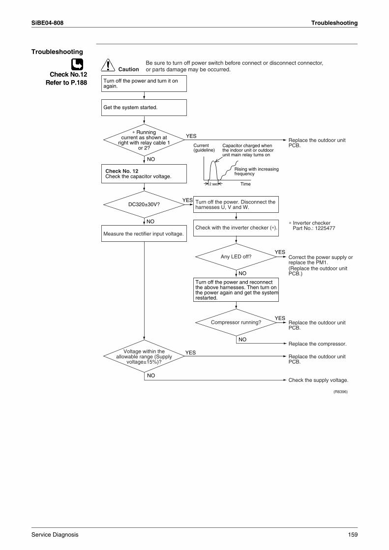
SiBE04-808 Troubleshooting
Troubleshooting
Check No.12Refer to P.188
(R8396)
CautionBe sure to turn off power switch before connect or disconnect connector, or parts damage may be occurred.
YES
Current (guideline)
2 sec Time
NO
NO
YES
YES
NO
YES
NO
YES
NO
Turn off the power and turn it on again.
Check No. 12Check the capacitor voltage.
Check with the inverter checker (∗).Measure the rectifier input voltage.
Get the system started.
Turn off the power. Disconnect the harnesses U, V and W.
Turn off the power and reconnect the above harnesses. Then turn on the power again and get the system restarted.
Compressor running?
DC320±30V?
Any LED off?
∗ Running current as shown at
right with relay cable 1 or 2?
Voltage within the allowable range (Supply
voltage±15%)?
Replace the outdoor unit PCB.
Replace the outdoor unit PCB.
Replace the outdoor unit PCB.
Check the supply voltage.
Replace the compressor.
Capacitor charged when the indoor unit or outdoor unit main relay turns on
Rising with increasing frequency
Correct the power supply or replace the PM1.(Replace the outdoor unit PCB.)
∗ Inverter checkerPart No.: 1225477
Service Diagnosis 159
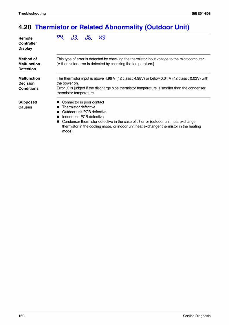
Troubleshooting SiBE04-808
4.20 Thermistor or Related Abnormality (Outdoor Unit)
Remote Controller Display
P4, J3, J6, H9
Method of Malfunction Detection
This type of error is detected by checking the thermistor input voltage to the microcomputer.[A thermistor error is detected by checking the temperature.]
Malfunction Decision Conditions
The thermistor input is above 4.96 V (42 class : 4.98V) or below 0.04 V (42 class : 0.02V) with the power on.Error J3 is judged if the discharge pipe thermistor temperature is smaller than the condenser thermistor temperature.
Supposed Causes
Connector in poor contactThermistor defectiveOutdoor unit PCB defectiveIndoor unit PCB defectiveCondenser thermistor defective in the case of J3 error (outdoor unit heat exchanger thermistor in the cooling mode, or indoor unit heat exchanger thermistor in the heating mode)
160 Service Diagnosis
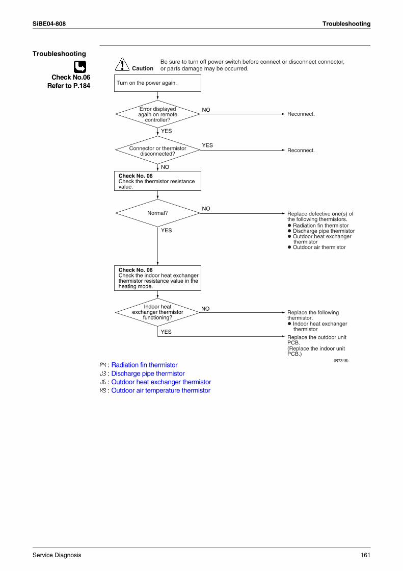
SiBE04-808 Troubleshooting
Troubleshooting
Check No.06Refer to P.184
P4 : Radiation fin thermistorJ3 : Discharge pipe thermistorJ6 : Outdoor heat exchanger thermistorH9 : Outdoor air temperature thermistor
CautionBe sure to turn off power switch before connect or disconnect connector, or parts damage may be occurred.
(R7346)
NO
YES
YES
YES
NO
NO
NO
YES
Turn on the power again.
Normal?
Reconnect.
Reconnect.
Replace defective one(s) of the following thermistors.
Radiation fin thermistor Discharge pipe thermistor Outdoor heat exchanger thermistor
Outdoor air thermistor
Indoor heat exchanger thermistor
Replace the following thermistor.
Replace the outdoor unit PCB.(Replace the indoor unit PCB.)
Connector or thermistor disconnected?
Error displayed again on remote
controller?
Indoor heat exchanger thermistor
functioning?
Check No. 06Check the thermistor resistance value.
Check No. 06Check the indoor heat exchanger thermistor resistance value in the heating mode.
Service Diagnosis 161
Troubleshooting SiBE04-808
4.21 Electrical Box Temperature Rise
Remote Controller Display
L3
Method of Malfunction Detection
An electrical box temperature rise is detected by checking the radiation fin thermistor with the compressor off.
Malfunction Decision Conditions
With the compressor off, the radiation fin temperature is above 80°C (95°C ). (Reset is made when the temperature drops below 70°C (80°C ).) : value for 50 class
Supposed Causes
Fin temperature rise due to defective outdoor unit fanFin temperature rise due to short-circuitFin thermistor defectiveConnector in poor contactOutdoor unit PCB defective
162 Service Diagnosis
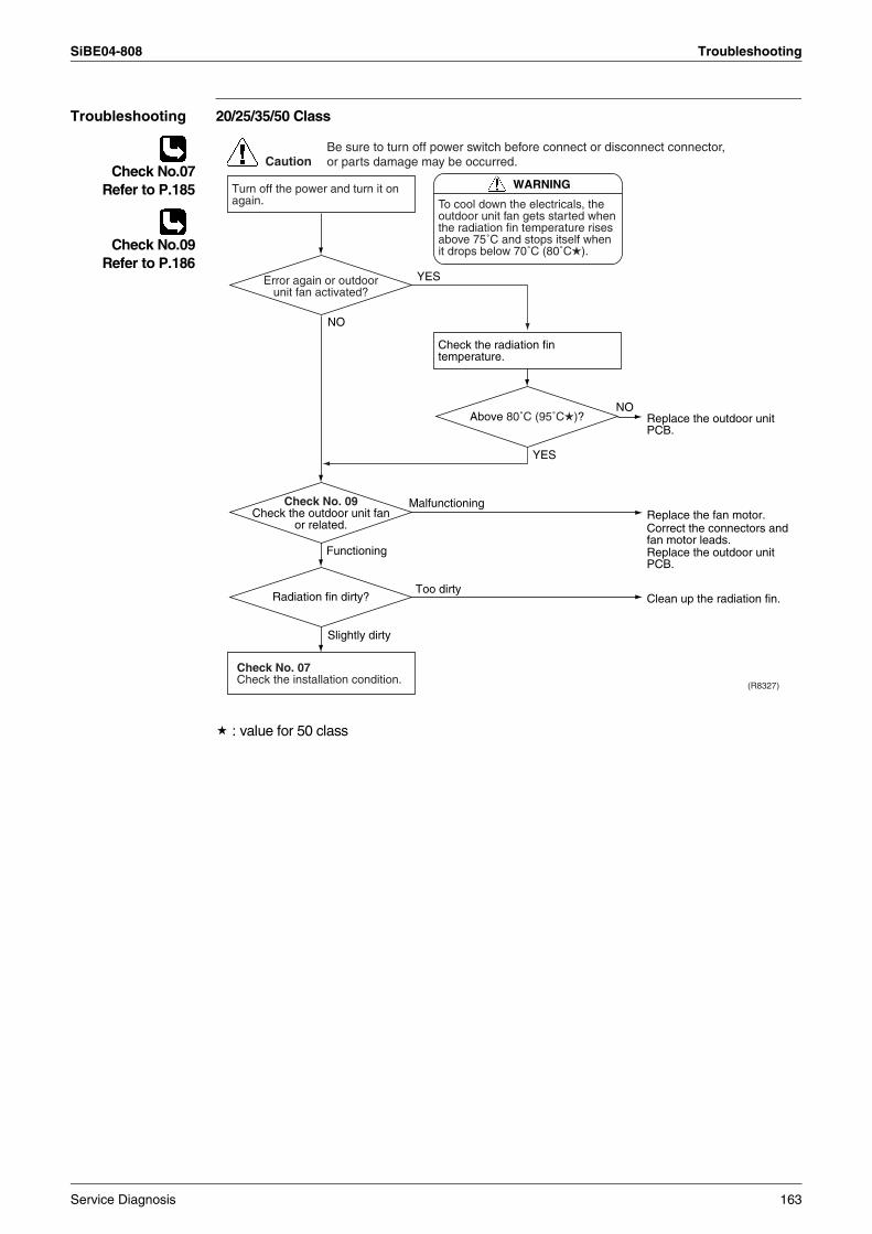
SiBE04-808 Troubleshooting
Troubleshooting 20/25/35/50 Class
Check No.07Refer to P.185
Check No.09Refer to P.186
: value for 50 class
(R8327)
CautionBe sure to turn off power switch before connect or disconnect connector, or parts damage may be occurred.
YES
NO
Slightly dirty
Malfunctioning
Too dirty
Functioning
NO
YES
WARNING
To cool down the electricals, the outdoor unit fan gets started when the radiation fin temperature rises above 75˚C and stops itself when it drops below 70˚C (80˚C ).
Turn off the power and turn it on again.
Check the radiation fin temperature.
Check No. 07Check the installation condition.
Radiation fin dirty?
Above 80˚C (95˚C )?
Check No. 09Check the outdoor unit fan
or related.
Error again or outdoor unit fan activated?
Replace the outdoor unit PCB.
Replace the outdoor unit PCB.
Replace the fan motor.Correct the connectors and fan motor leads.
Clean up the radiation fin.
Service Diagnosis 163
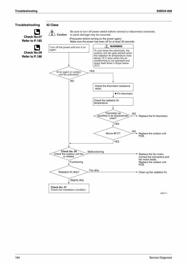
Troubleshooting SiBE04-808
Troubleshooting 42 Class
Check No.07Refer to P.185
Check No.09Refer to P.186
(R8311)
CautionBe sure to turn off power switch before connect or disconnect connector, or parts damage may be occurred.
YES
Fin thermistor
NO
Slightly dirty
Malfunctioning
Too dirty
Functioning
NO
YES
NO
YES
WARNING
To cool down the electricals, the outdoor unit fan gets started when the radiation fin temperature rises above 75˚C even when the air conditioning is not operated and stops itself when it drops below 70˚C.
(Precaution before turning on the power again) Make sure the power has been off for at least 30 seconds.
Turn off the power and turn it on again.
Check the radiation fin temperature.
Check the thermistor resistance value.
Check No. 07Check the installation condition.
Radiation fin dirty?
Above 80˚C?
Thermistor as specified in its characteristic
chart?
Check No. 09Check the outdoor unit fan
or related.
Error again or outdoor unit fan activated?
Replace the fin thermistor.
Replace the outdoor unit PCB.
Replace the outdoor unit PCB.
Replace the fan motor.Correct the connectors and fan motor leads.
Clean up the radiation fin.
164 Service Diagnosis
SiBE04-808 Troubleshooting
4.22 Radiation Fin Temperature Rise4.22.1 20/25/35 Class
Remote Controller Display
L4
Method of Malfunction Detection
A radiation fin temperature rise is detected by checking the radiation fin thermistor with the compressor on.
Malfunction Decision Conditions
If the radiation fin temperature with the compressor on is above 90°C.Clearing condition : when the temperature drops below 85°C.If a radiation fin temperature rise takes place 4 times successively, the system will be shut down.The error counter will reset itself if this or any other error does not occur during the following 60-minute compressor running time (total time).
Supposed Causes
Fin temperature rise due to defective outdoor unit fanFin temperature rise due to short-circuitFin thermistor defectiveConnector in poor contactOutdoor unit PCB defectiveSilicon grease is not applied properly on the heat radiation fin after replacing outdoor unit PCB
Service Diagnosis 165
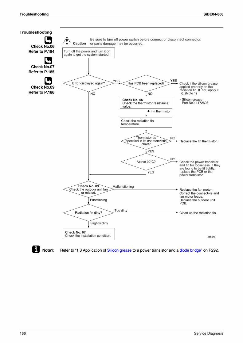
Troubleshooting SiBE04-808
Troubleshooting
Check No.06Refer to P.184
Check No.07Refer to P.185
Check No.09Refer to P.186
Note1: Refer to “1.3 Application of Silicon grease to a power transistor and a diode bridge” on P292.
(R7339)
CautionBe sure to turn off power switch before connect or disconnect connector, or parts damage may be occurred.
NO
Slightly dirty
Malfunctioning
Too dirty
Functioning
NO
YES
NO
YES
Fin thermistor
Turn off the power and turn it on again to get the system started.
Check the radiation fin temperature.
Check No. 07Check the installation condition.
NO
YESYES
Radiation fin dirty?
Above 90˚C?
Thermistor as specified in its characteristic
chart?
Check No. 06Check the thermistor resistance value.
Check No. 09Check the outdoor unit fan
or related.
Error displayed again? Has PCB been replaced?
Replace the fin thermistor.
Check if the silicon grease applied properly on the radiation fin. If not, apply it (∗). (Note 1)
Check the power transistor and fin for looseness. If they are found to be fit tightly, replace the PCB or the power transistor.
Replace the outdoor unit PCB.
Replace the fan motor.Correct the connectors and fan motor leads.
Clean up the radiation fin.
∗ Silicon greasePart No.: 1172698
166 Service Diagnosis
SiBE04-808 Troubleshooting
4.22.2 42 Class
Remote Controller Display
L4
Method of Malfunction Detection
A radiation fin temperature rise is detected by checking the radiation fin thermistor with the compressor on.
Malfunction Decision Conditions
If the radiation fin temperature with the compressor on is above 93°C.If a radiation fin temperature rise takes place 255 times successively, the system will be shut down.The error counter will reset itself if this or any other error does not occur during the following 60-minute compressor running time (total time).
Supposed Causes
Fin temperature rise due to defective outdoor unit fanFin temperature rise due to short-circuitFin thermistor defectiveConnector in poor contactOutdoor unit PCB defectiveSilicon grease is not applied properly on the heat radiation fin after replacing outdoor unit PCB
Service Diagnosis 167
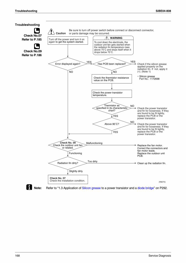
Troubleshooting SiBE04-808
Troubleshooting
Check No.07Refer to P.185
Check No.09Refer to P.186
Note: Refer to “1.3 Application of Silicon grease to a power transistor and a diode bridge” on P292.
(R8070)
CautionBe sure to turn off power switch before connect or disconnect connector, or parts damage may be occurred.
NO
Slightly dirty
Malfunctioning
Too dirty
Functioning
NO
YES
NO
YES
Turn off the power and turn it on again to get the system started.
Check the power transistor temperature.
Check No. 07Check the installation condition.
NO
YESYES
Radiation fin dirty?
Above 90˚C?
Thermistor as specified in its characteristic
chart?
Check the thermistor resistance value on the PCB.
Check No. 09Check the outdoor unit fan
or related.
Error displayed again? Has PCB been replaced?
Check the power transistor and fin for looseness. If they are found to be fit tightly, replace the PCB or the power transistor.
Check if the silicon grease applied properly on the radiation fin. If not, apply it (∗). (Note 1)
Check the power transistor and fin for looseness. If they are found to be fit tightly, replace the PCB or the power transistor.
Replace the outdoor unit PCB.
Replace the fan motor.Correct the connectors and fan motor leads.
Clean up the radiation fin.
∗ Silicon greasePart No.: 1172698
WARNING
To cool down the electricals, the outdoor unit fan gets started when the radiation fin temperature rises above 75˚C and stops itself when it drops below 70˚C.
168 Service Diagnosis
SiBE04-808 Troubleshooting
4.22.3 50 Class
Remote Controller Display
L4
Method of Malfunction Detection
A radiation fin temperature rise is detected by checking the radiation fin thermistor with the compressor on.
Malfunction Decision Conditions
If the radiation fin temperature with the compressor on is above 105°C,The error is cleared when the temperature drops below 99°C.If a radiation fin temperature rise takes place 4 times successively, the system will be shut down.The error counter will reset itself if this or any other error does not occur during the following 60-minute compressor running time (total time).
Supposed Causes
Fin temperature rise due to defective outdoor unit fanFin temperature rise due to short-circuitFin thermistor defectiveConnector in poor contactOutdoor unit PCB defectiveSilicon grease is not applied properly on the heat radiation fin after replacing outdoor unit PCB
Service Diagnosis 169
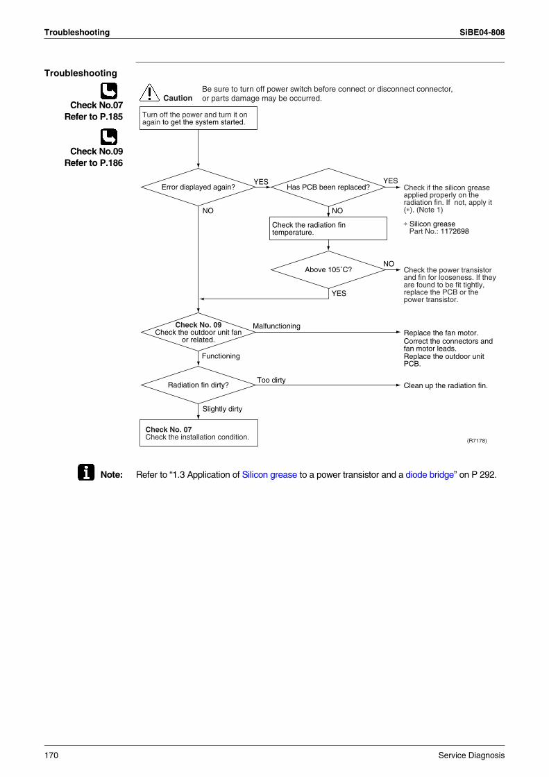
Troubleshooting SiBE04-808
Troubleshooting
Check No.07Refer to P.185
Check No.09Refer to P.186
Note: Refer to “1.3 Application of Silicon grease to a power transistor and a diode bridge” on P 292.
CautionBe sure to turn off power switch before connect or disconnect connector, or parts damage may be occurred.
(R7178)
NO
Slightly dirty
Malfunctioning
Too dirty
Functioning
NO
YES
Turn off the power and turn it on again to get the system started.
Check the radiation fin temperature.
Check No. 07Check the installation condition.
NO
YESYES
Radiation fin dirty?
Above 105˚C?
Check No. 09Check the outdoor unit fan
or related.
Error displayed again? Has PCB been replaced? Check if the silicon grease applied properly on the radiation fin. If not, apply it (∗). (Note 1)
Check the power transistor and fin for looseness. If they are found to be fit tightly, replace the PCB or the power transistor.
Replace the outdoor unit PCB.
Replace the fan motor.Correct the connectors and fan motor leads.
Clean up the radiation fin.
∗ Silicon greasePart No.: 1172698
170 Service Diagnosis
SiBE04-808 Troubleshooting
4.23 Output Over Current Detection
Remote Controller Display
L5
Method of Malfunction Detection
An output over-current is detected by checking the current that flows in the inverter DC section.
Malfunction Decision Conditions
A position signal error occurs while the compressor is running.A speed error occurs while the compressor is running.An output over-current input is fed from the output over-current detection circuit to the microcomputer.The system will be shut down if the error occurs 255 times (20/25/35 class), 8 times (42 class) or 16 times (50 class).Clearing condition: Continuous run for about 10 minutes (20/25/35/42 class) or 5 minutes (50 class) (normal)
Supposed Causes
Over-current due to defective power transistorOver-current due to wrong internal wiringOver-current due to abnormal supply voltageOver-current due to defective PCBError detection due to defective PCBOver-current due to closed stop valveOver-current due to compressor failureOver-current due to poor installation condition
Service Diagnosis 171
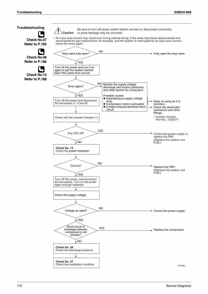
Troubleshooting SiBE04-808
Troubleshooting
Check No.07Refer to P.185
Check No.08Refer to P.186
Check No.13Refer to P.188
(R7238)
CautionBe sure to turn off power switch before connect or disconnect connector, or parts damage may be occurred.
NO
YES
NO
YES
NO
YES
YES
NO
NO
YES
YES
NO
Monitor the supply voltage, discharge and suction pressures, and other factors for a long term.
Possible causes Instantaneous supply voltage drop
Compressor motor overloaded Contact-induced electrical short-circuit
∗ An input over-current may result from wrong internal wiring. If the wires have been disconnected and reconnected for part replacement, for example, and the system is interrupted by an input over-current, check the wires again.
Check No. 08Check the discharge pressure.
Check No. 13Check the power transistor.
Check No. 07Check the installation condition.
Check with the inverter checker (∗).
Turn off the power and disconnect the harnesses U, V and W.
Turn off the power, and reconnect the harnesses. Turn on the power again and get restarted.
Turn off the power and turn it on again to get the system started. See if the same error occurs.
Check the supply voltage.
Keep on using as it is (monitor).Check the electricals' connectors and other fittings.
Fully open the stop valve.
Correct the power supply.
Replace the compressor.
Correct the power supply or replace the PM1.(Replace the outdoor unit PCB.)
Replace the PM1.(Replace the outdoor unit PCB.)
Normal?
Error again?
Stop valve fully open?
Voltage as rated?
Any LED off?
∗ Inverter checkerPart No.: 1225477
Short-circuit or breakage between compressor's coil
phases?
172 Service Diagnosis
SiBE04-808 Troubleshooting
4.24 Insufficient Gas4.24.1 20/25/35/42 Class
Remote Controller Display
U0
Method of Malfunction Detection
Gas shortage detection I:Gas shortage is detected by checking the input current value and the compressor running frequency. If the gas is short, the input current is smaller than the normal value.
Gas shortage detection II:Gas shortage is detected by checking the discharge temperature and the opening of the electronic expansion valve. If the gas is short, the discharge temperature tends to rise.
Gas shortage detection III (20/25/35 class only): A gas shortage is detected by checking the difference between inhale and exhale temperature.
Malfunction Decision Conditions
Gas shortage detection I: 20/25/35 classThe following conditions continue for 7 minutes.
Input current × input voltage ≤ 640 / 256 × output frequencyOutput frequency > 55 (Hz)
42 class The following conditions continue for 7 minutes.
Input current × input voltage ≤ 3446 / 256 × output frequency - 346 (W)Output frequency > 48 (Hz)
Gas shortage detection II:20/25/35 classThe following conditions continue for 80 seconds.
Target opening of the electronic expansion valve ≥ 480 (pulse)Discharge temperature > 255 / 256 × target discharge temperature +30 (°C)
42 class The following conditions continue for 80 seconds.
Target opening of the electronic expansion valve ≥ 450 (pulse)Discharge temperature > 128 / 128 × target discharge temperature +40 (°C)
Gas shortage detection III (20/25/35 class only):When the difference of the temperature is smaller than , it is regarded as insufficient gas.
If a gas shortage error takes place 4 times straight, the system will be shut down. The error counter will reset itself if this or any other error does not occur during the following 60-minute compressor running time (total time).
Supposed Causes
Refrigerant shortage (refrigerant leakage)Poor compression performance of compressorDischarge pipe thermistor disconnected, or indoor unit or outdoor unit heat exchanger thermistor disconnected, room or outdoor air temperature thermistor disconnectedStop valve closedElectronic expansion valve defective
Coolingroom temperature – indoor heat exchanger temperature 4.0°C
outdoor heat exchanger temperature – outdoor temperature 4.0°C
Heatingindoor heat exchanger temperature – room temperature 3.0°C
outdoor temperature – outdoor heat exchanger temperature 3.0°C
Service Diagnosis 173
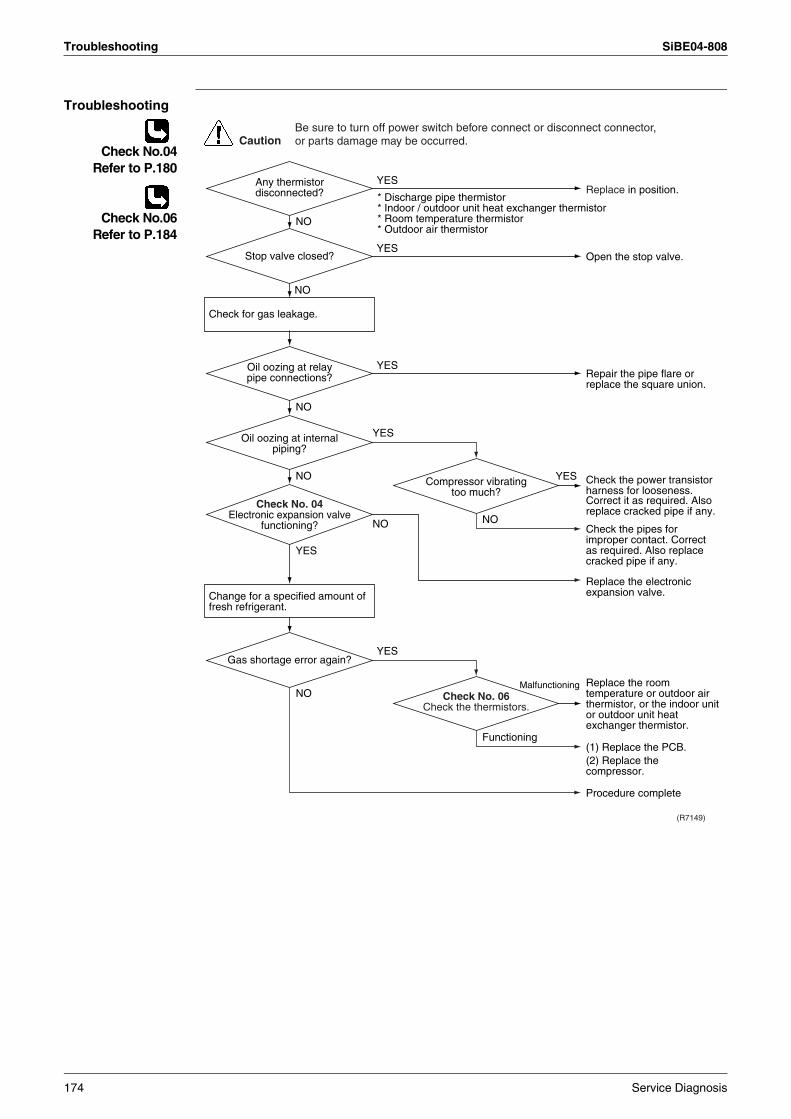
Troubleshooting SiBE04-808
Troubleshooting
Check No.04Refer to P.180
Check No.06Refer to P.184
(R7149)
CautionBe sure to turn off power switch before connect or disconnect connector, or parts damage may be occurred.
YES
Malfunctioning
NO
NO
YES
YES
YES
NO
Functioning
YES
NO
NO
YES
NO
NO
YES
* Discharge pipe thermistor* Indoor / outdoor unit heat exchanger thermistor* Room temperature thermistor* Outdoor air thermistor
Check for gas leakage.
Change for a specified amount of fresh refrigerant.
Check No. 04Electronic expansion valve
functioning?
Replace in position.
Open the stop valve.
Repair the pipe flare or replace the square union.
Check the power transistor harness for looseness.Correct it as required. Also replace cracked pipe if any.
Check the pipes for improper contact. Correct as required. Also replace cracked pipe if any.
Replace the electronic expansion valve.
Replace the room temperature or outdoor air thermistor, or the indoor unit or outdoor unit heat exchanger thermistor.
(1) Replace the PCB.(2) Replace the compressor.
Procedure complete
Gas shortage error again?
Oil oozing at internal piping?
Stop valve closed?
Compressor vibrating too much?
Oil oozing at relay pipe connections?
Any thermistor disconnected?
Check No. 06Check the thermistors.
174 Service Diagnosis
SiBE04-808 Troubleshooting
4.24.2 50 Class
Remote Controller Display
U0
Method of Malfunction Detection
Gas shortage detection I : A gas shortage is detected by checking the CT-detected input current value and the compressor running frequency.
Gas shortage detection II : A gas shortage is detected by checking the difference between indoor unit heat exchanger temperature and room temperature as well as the difference between outdoor unit heat exchanger temperature and room temperature.
Malfunction Decision Conditions
Gas shortage detection I : DC current ≤ (A/Hz) × Output frequency +However, when the status of running frequency > 55 (Hz) is kept on for a certain time.Note : The values are different from model to model.
Gas shortage detection II : If a gas shortage error takes place 4 times successively, the system will be shut down. The error counter will reset itself if this or any other error does not occur during the following 60-minute compressor running time (total time).
Supposed Causes
Refrigerant shortage (refrigerant leakage)Poor compression performance of compressorDischarge pipe thermistor disconnected, or indoor unit or outdoor unit heat exchanger thermistor disconnected, room or outside air temperature thermistor disconnectedStop valve closedElectronic expansion valve defective
50 class 18 / 1000 0.7
Service Diagnosis 175

Troubleshooting SiBE04-808
Troubleshooting
Check No.04Refer to P.180
Check No.06Refer to P.184
(R7149)
CautionBe sure to turn off power switch before connect or disconnect connector, or parts damage may be occurred.
YES
Malfunctioning
NO
NO
YES
YES
YES
NO
Functioning
YES
NO
NO
YES
NO
NO
YES
* Discharge pipe thermistor* Indoor / outdoor unit heat exchanger thermistor* Room temperature thermistor* Outdoor air thermistor
Check for gas leakage.
Change for a specified amount of fresh refrigerant.
Check No. 04Electronic expansion valve
functioning?
Replace in position.
Open the stop valve.
Repair the pipe flare or replace the square union.
Check the power transistor harness for looseness.Correct it as required. Also replace cracked pipe if any.
Check the pipes for improper contact. Correct as required. Also replace cracked pipe if any.
Replace the electronic expansion valve.
Replace the room temperature or outdoor air thermistor, or the indoor unit or outdoor unit heat exchanger thermistor.
(1) Replace the PCB.(2) Replace the compressor.
Procedure complete
Gas shortage error again?
Oil oozing at internal piping?
Stop valve closed?
Compressor vibrating too much?
Oil oozing at relay pipe connections?
Any thermistor disconnected?
Check No. 06Check the thermistors.
176 Service Diagnosis
SiBE04-808 Troubleshooting
4.25 Low-voltage Detection or Over-voltage Detection
Remote Controller Display
U2
Method of Malfunction Detection
An abnormal voltage rise or drop is detected by checking the detection circuit or DC voltage detection circuit.
Malfunction Decision Conditions
20/25/35 classAn over-voltage signal is fed from the over-voltage detection circuit to the microcomputer (The voltage is over 400V).The system will be shut down if the error occurs 255 times.Clearing condition: Continuous run for about 10 minutes (normal)
42/50 classAn over-voltage signal is fed from the over-voltage detection circuit to the microcomputer, or the voltage being detected by the DC voltage detection circuit is judged to be below 150 V for 0.1 second.The system will be shut down if the error occurs 255 times (42 class) or 16 times (50 class).Clearing condition: Continuous run for about 10 minutes (42 class) or 60 minutes (50 class) (normal)
Supposed Causes
Supply voltage not as specifiedOver-voltage detector or DC voltage detection circuit defectivePAM control part(s) defectiveShort circuit inside the fan motor winding.
Service Diagnosis 177
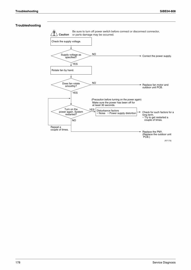
Troubleshooting SiBE04-808
Troubleshooting
Correct the power supply.
Replace the PM1.
Check for such factors for a long term.∗ Try to get restarted a
couple of times.
(R7179)
CautionBe sure to turn off power switch before connect or disconnect connector, or parts damage may be occurred.
NO
YES
YES
NO
YES
(Precaution before turning on the power again)
NOReplace fan motor and outdoor unit PCB.
(Replace the outdoor unit PCB.)
Check the supply voltage.
Rotate fan by hand.
Disturbance factors ∗ Noise ∗ Power supply distortion
Repeat a couple of times.
Make sure the power has been off for at least 30 seconds.
Turn on the power again. System
restarted?
Does fan rotate smoothly?
Supply voltage as specified?
178 Service Diagnosis
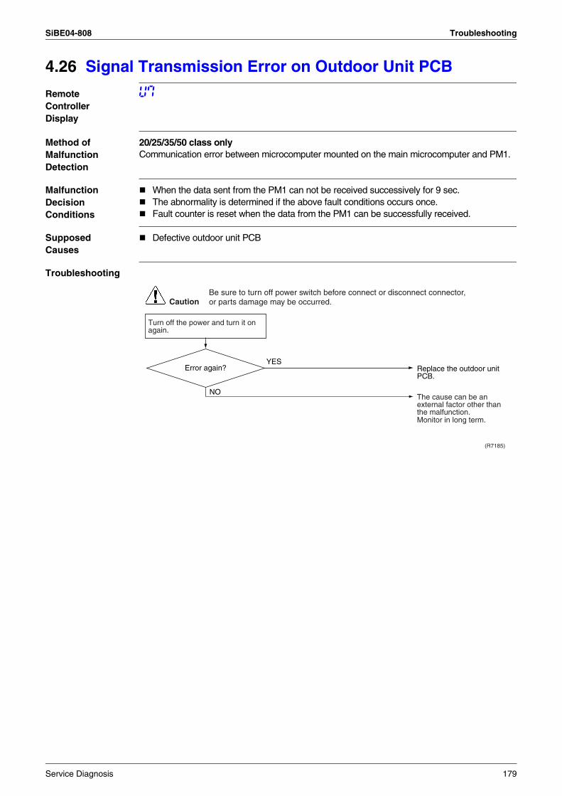
SiBE04-808 Troubleshooting
4.26 Signal Transmission Error on Outdoor Unit PCB
Remote Controller Display
U7
Method of Malfunction Detection
20/25/35/50 class onlyCommunication error between microcomputer mounted on the main microcomputer and PM1.
Malfunction Decision Conditions
When the data sent from the PM1 can not be received successively for 9 sec. The abnormality is determined if the above fault conditions occurs once.Fault counter is reset when the data from the PM1 can be successfully received.
Supposed Causes
Defective outdoor unit PCB
Troubleshooting
(R7185)
CautionBe sure to turn off power switch before connect or disconnect connector, or parts damage may be occurred.
NO
YES
Turn off the power and turn it on again.
Error again? Replace the outdoor unit PCB.
Monitor in long term.
The cause can be an external factor other than the malfunction.
Service Diagnosis 179
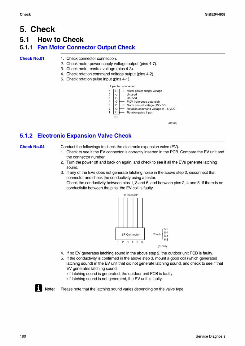
Check SiBE04-808
5. Check5.1 How to Check5.1.1 Fan Motor Connector Output Check
Check No.01 1. Check connector connection.2. Check motor power supply voltage output (pins 4-7).3. Check motor control voltage (pins 4-3).4. Check rotation command voltage output (pins 4-2).5. Check rotation pulse input (pins 4-1).
5.1.2 Electronic Expansion Valve Check
Check No.04 Conduct the followings to check the electronic expansion valve (EV).1. Check to see if the EV connector is correctly inserted in the PCB. Compare the EV unit and
the connector number.2. Turn the power off and back on again, and check to see if all the EVs generate latching
sound.3. If any of the EVs does not generate latching noise in the above step 2, disconnect that
connector and check the conductivity using a tester.Check the conductivity between pins 1, 3 and 6, and between pins 2, 4 and 5. If there is no conductivity between the pins, the EV coil is faulty.
4. If no EV generates latching sound in the above step 2, the outdoor unit PCB is faulty.5. If the conductivity is confirmed in the above step 3, mount a good coil (which generated
latching sound) in the EV unit that did not generate latching sound, and check to see if that EV generates latching sound.∗If latching sound is generated, the outdoor unit PCB is faulty.∗If latching sound is not generated, the EV unit is faulty.
Note: Please note that the latching sound varies depending on the valve type.
7654321
Motor power supply voltageUnusedUnusedP.0V (reference potential)Motor control voltage (15 VDC)Rotation command voltage (1~ 5 VDC)Rotation pulse input
Upper fan connector
S1
(R6940)
Harness 6P
6P Connector Check
5-25-46-16-3
1 2 3 4 5 6(R1082)
180 Service Diagnosis
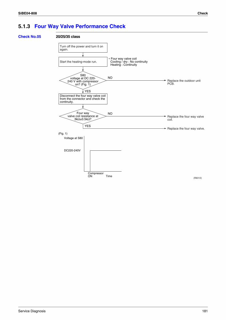
SiBE04-808 Check
5.1.3 Four Way Valve Performance Check
Check No.05 20/25/35 class
(R8312)
NO
YES
YES
NO
(Fig. 1)
Voltage at S80
DC220-240V
ONCompressor
Time
Turn off the power and turn it on again.
Disconnect the four way valve coil from the connector and check the continuity.
Start the heating-mode run.∗ Four way valve coil
Cooling / dry : No continuity Heating : Continuity
Replace the outdoor unit PCB.
Replace the four way valve coil.
Replace the four way valve.
Four way valve coil resistance at
3kΩ±0.5kΩ?
S80 voltage at DC 220-
240 V with compressor on? (Fig. 1)
Service Diagnosis 181
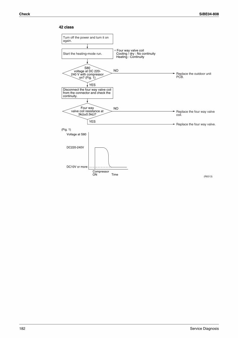
Check SiBE04-808
42 class
(R8313)
(Fig. 1)
Voltage at S80
DC220-240V
DC10V or more
ONCompressor
Time
NO
YES
YES
NO
Turn off the power and turn it on again.
Disconnect the four way valve coil from the connector and check the continuity.
Start the heating-mode run.∗ Four way valve coil
Cooling / dry : No continuity Heating : Continuity
Replace the outdoor unit PCB.
Replace the four way valve coil.
Replace the four way valve.
Four way valve coil resistance at
3kΩ±0.5kΩ?
S80 voltage at DC 220-
240 V with compressor on? (Fig. 1)
182 Service Diagnosis
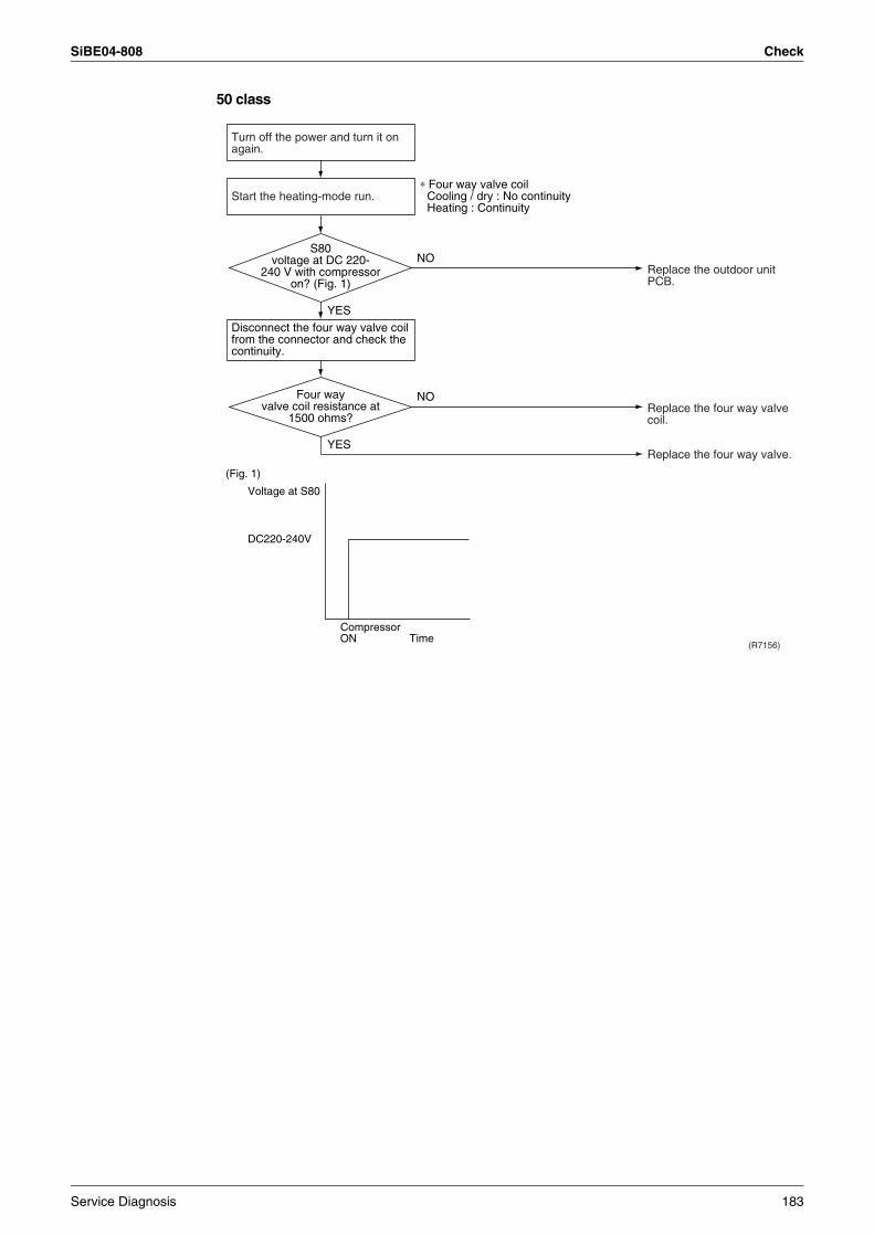
SiBE04-808 Check
50 class
(R7156)
NO
YES
YES
NO
(Fig. 1)
Voltage at S80
DC220-240V
ONCompressor
Time
Turn off the power and turn it on again.
Disconnect the four way valve coil from the connector and check the continuity.
Start the heating-mode run.∗ Four way valve coil
Cooling / dry : No continuity Heating : Continuity
Replace the outdoor unit PCB.
Replace the four way valve coil.
Replace the four way valve.
Four way valve coil resistance at
1500 ohms?
S80 voltage at DC 220-
240 V with compressor on? (Fig. 1)
Service Diagnosis 183
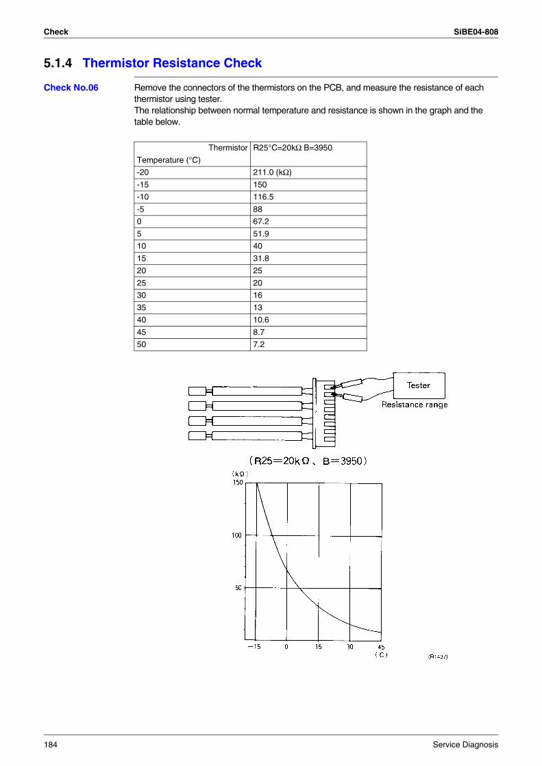
Check SiBE04-808
5.1.4 Thermistor Resistance Check
Check No.06 Remove the connectors of the thermistors on the PCB, and measure the resistance of each thermistor using tester.The relationship between normal temperature and resistance is shown in the graph and the table below.
Thermistor R25°C=20kΩ B=3950
Temperature (°C)
-20 211.0 (kΩ)
-15 150
-10 116.5
-5 88
0 67.2
5 51.9
10 40
15 31.8
20 25
25 20
30 16
35 13
40 10.6
45 8.7
50 7.2
184 Service Diagnosis
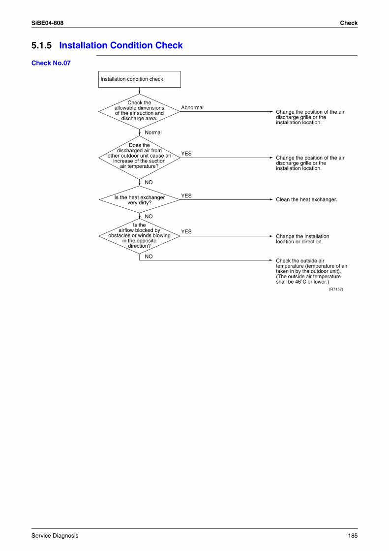
SiBE04-808 Check
5.1.5 Installation Condition Check
Check No.07
Installation condition check
Normal
(R7157)
Abnormal
YES
YES
YES
NO
NO
NO
Is the heat exchanger very dirty?
Check the allowable dimensions of the air suction and
discharge area.
Is the airflow blocked by
obstacles or winds blowing in the opposite
direction?
Does the discharged air from
other outdoor unit cause an increase of the suction
air temperature?
Change the position of the air discharge grille or the installation location.
Change the position of the air discharge grille or the installation location.
Change the installation location or direction.
Check the outside air temperature (temperature of air taken in by the outdoor unit). (The outside air temperature shall be 46˚C or lower.)
Clean the heat exchanger.
Service Diagnosis 185
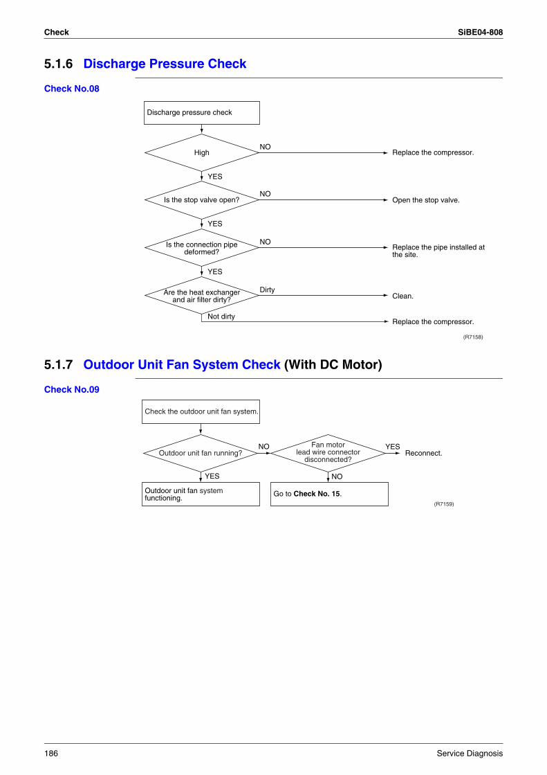
Check SiBE04-808
5.1.6 Discharge Pressure Check
Check No.08
5.1.7 Outdoor Unit Fan System Check (With DC Motor)
Check No.09
(R7158)
Not dirty
YES
YES
Dirty
NO
NO
NO
YES
Are the heat exchanger and air filter dirty?
Is the connection pipe deformed?
Is the stop valve open?
High Replace the compressor.
Open the stop valve.
Replace the pipe installed at the site.
Clean.
Replace the compressor.
Discharge pressure check
(R7159)
YES
YESNO
NO
Outdoor unit fan system functioning.
Check the outdoor unit fan system.
Go to Check No. 15.
Outdoor unit fan running?Fan motor
lead wire connector disconnected?
Reconnect.
186 Service Diagnosis
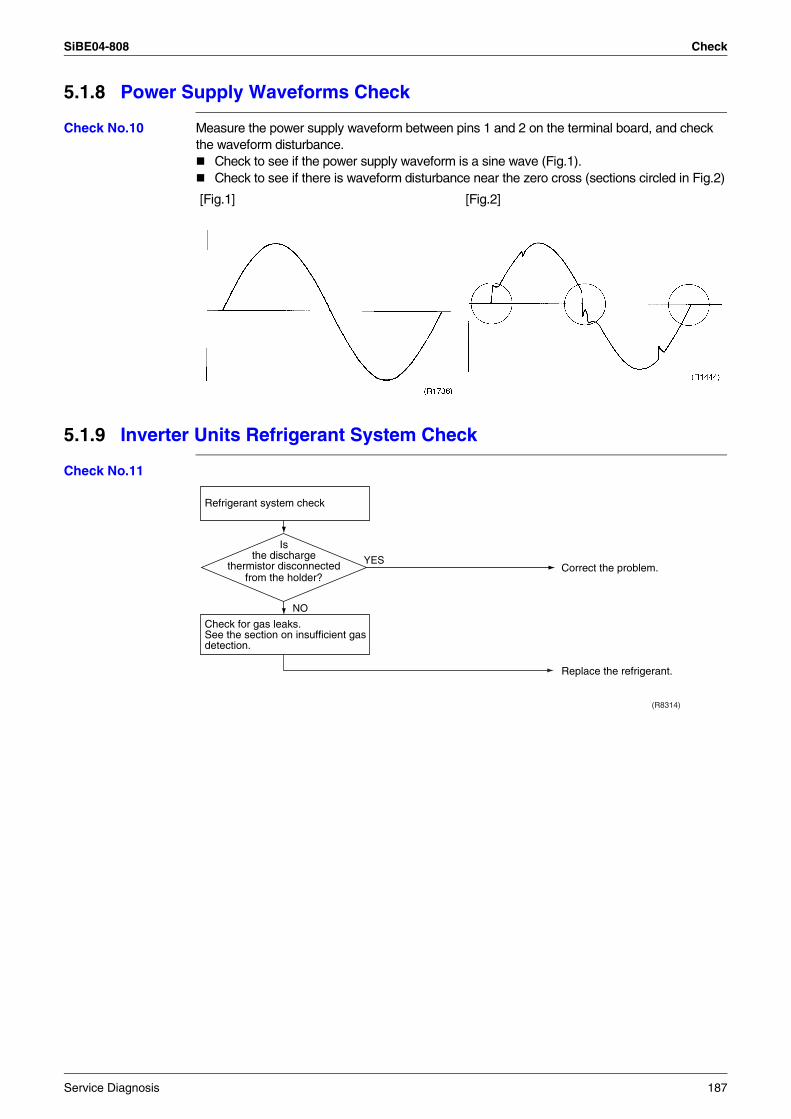
SiBE04-808 Check
5.1.8 Power Supply Waveforms Check
Check No.10 Measure the power supply waveform between pins 1 and 2 on the terminal board, and check the waveform disturbance.
Check to see if the power supply waveform is a sine wave (Fig.1).Check to see if there is waveform disturbance near the zero cross (sections circled in Fig.2)
5.1.9 Inverter Units Refrigerant System Check
Check No.11
[Fig.1] [Fig.2]
Refrigerant system check
Check for gas leaks.See the section on insufficient gas detection.
(R8314)
YES
NO
Correct the problem.
Replace the refrigerant.
Is the discharge
thermistor disconnected from the holder?
Service Diagnosis 187
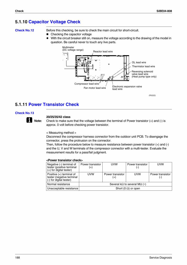
Check SiBE04-808
5.1.10 Capacitor Voltage Check
Check No.12 Before this checking, be sure to check the main circuit for short-circuit.Checking the capacitor voltageWith the circuit breaker still on, measure the voltage according to the drawing of the model in question. Be careful never to touch any live parts.
5.1.11 Power Transistor Check
Check No.1320/25/35/42 class
Note: Check to make sure that the voltage between the terminal of Power transistor (+) and (-) is approx. 0 volt before checking power transistor.
< Measuring method >Disconnect the compressor harness connector from the outdoor unit PCB. To disengage the connector, press the protrusion on the connector.Then, follow the procedure below to measure resistance between power transistor (+) and (-) and the U, V and W terminals of the compressor connector with a multi-tester. Evaluate the measurement results for a pass/fail judgment.
<Power transistor check>
OL lead wire
Thermistor lead wire
Fan motor lead wire Electronic expansion valvelead wire
Reversing solenoid valve lead wire(Heat pump type only)
Compressor lead wire
Reactor lead wire
Multimeter(DC voltage range)
(R5222)
Negative (-) terminal of tester (positive terminal (+) for digital tester)
Power transistor (+)
UVW Power transistor (-)
UVW
Positive (+) terminal of tester (negative terminal (-) for digital tester)
UVW Power transistor (+)
UVW Power transistor (-)
Normal resistance Several kΩ to several MΩ (∗)
Unacceptable resistance Short (0 Ω) or open
188 Service Diagnosis
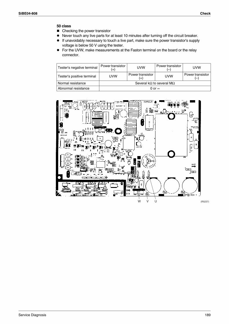
SiBE04-808 Check
50 classChecking the power transistorNever touch any live parts for at least 10 minutes after turning off the circuit breaker.If unavoidably necessary to touch a live part, make sure the power transistor's supply voltage is below 50 V using the tester.For the UVW, make measurements at the Faston terminal on the board or the relay connector.
Tester's negative terminal Power transistor (+) UVW Power transistor
(–) UVW
Tester's positive terminal UVW Power transistor (+) UVW Power transistor
(–)
Normal resistance Several kΩ to several MΩAbnormal resistance 0 or ∞
W V U (R5237)
Service Diagnosis 189
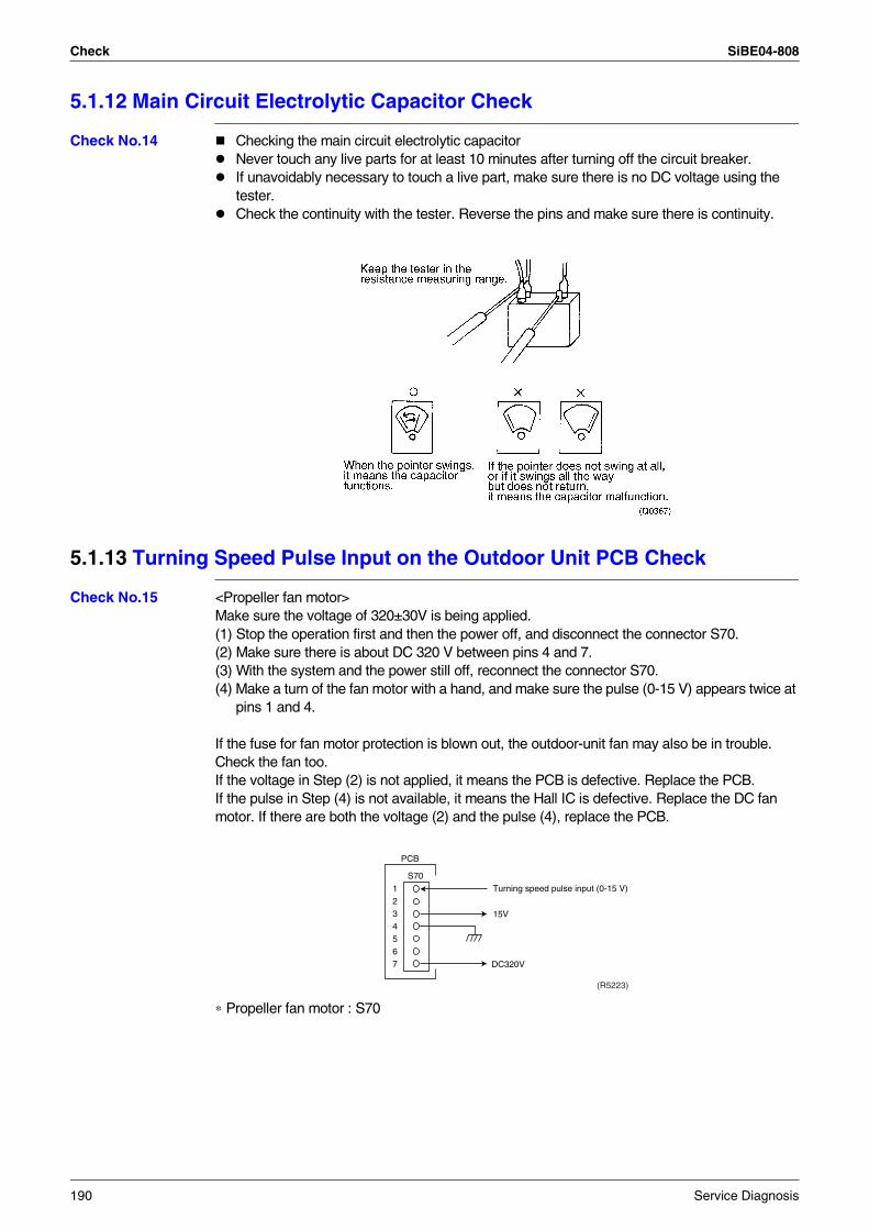
Check SiBE04-808
5.1.12 Main Circuit Electrolytic Capacitor Check
Check No.14 Checking the main circuit electrolytic capacitorNever touch any live parts for at least 10 minutes after turning off the circuit breaker.If unavoidably necessary to touch a live part, make sure there is no DC voltage using the tester.Check the continuity with the tester. Reverse the pins and make sure there is continuity.
5.1.13 Turning Speed Pulse Input on the Outdoor Unit PCB Check
Check No.15 <Propeller fan motor>Make sure the voltage of 320±30V is being applied.(1) Stop the operation first and then the power off, and disconnect the connector S70.(2) Make sure there is about DC 320 V between pins 4 and 7.(3) With the system and the power still off, reconnect the connector S70.(4) Make a turn of the fan motor with a hand, and make sure the pulse (0-15 V) appears twice at
pins 1 and 4.
If the fuse for fan motor protection is blown out, the outdoor-unit fan may also be in trouble. Check the fan too.If the voltage in Step (2) is not applied, it means the PCB is defective. Replace the PCB.If the pulse in Step (4) is not available, it means the Hall IC is defective. Replace the DC fan motor. If there are both the voltage (2) and the pulse (4), replace the PCB.
∗ Propeller fan motor : S70
1234567 DC320V
S70
PCB
Turning speed pulse input (0-15 V)
15V
(R5223)
190 Service Diagnosis
SiBE04-808
Removal Procedure 191
Part 7Removal Procedure
1. Indoor Unit...........................................................................................1921.1 Removal of Air filter ..............................................................................1921.2 Removal of Front Panel........................................................................1941.3 Removal of Front Grille ........................................................................1961.4 Removal of Horizontal Blades and Vertical Blades ..............................1991.5 Removal of Electrical Box ....................................................................2021.6 Removal of PCB...................................................................................2051.7 Removal of Heat Exchanger ................................................................2101.8 Removal of Fan Rotor ..........................................................................213
2. Outdoor Unit........................................................................................2192.1 20/25/35 Class .....................................................................................2192.2 42 Class ...............................................................................................2442.3 50 Class ...............................................................................................266
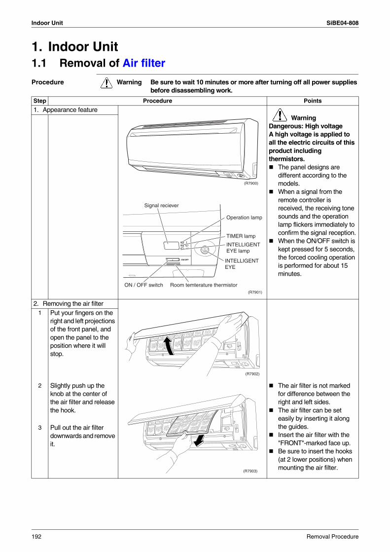
Indoor Unit SiBE04-808
1. Indoor Unit1.1 Removal of Air filter
Procedure Warning Be sure to wait 10 minutes or more after turning off all power supplies before disassembling work.
Step Procedure Points
1. Appearance featureWarning
Dangerous: High voltageA high voltage is applied to all the electric circuits of this product including thermistors.
The panel designs are different according to the models.When a signal from the remote controller is received, the receiving tone sounds and the operation lamp flickers immediately to confirm the signal reception.When the ON/OFF switch is kept pressed for 5 seconds, the forced cooling operation is performed for about 15 minutes.
2. Removing the air filter1 Put your fingers on the
right and left projections of the front panel, and open the panel to the position where it will stop.
2 Slightly push up the knob at the center of the air filter and release the hook.
The air filter is not marked for difference between the right and left sides.The air filter can be set easily by inserting it along the guides.Insert the air filter with the "FRONT"-marked face up.Be sure to insert the hooks (at 2 lower positions) when mounting the air filter.
3 Pull out the air filter downwards and remove it.
(R7900)
(R7901)
Signal reciever
Operation lamp
TIMER lamp
INTELLIGENTEYE lamp
INTELLIGENTEYE
ON / OFF switch Room temterature thermistor
(R7902)
(R7903)
192 Removal Procedure
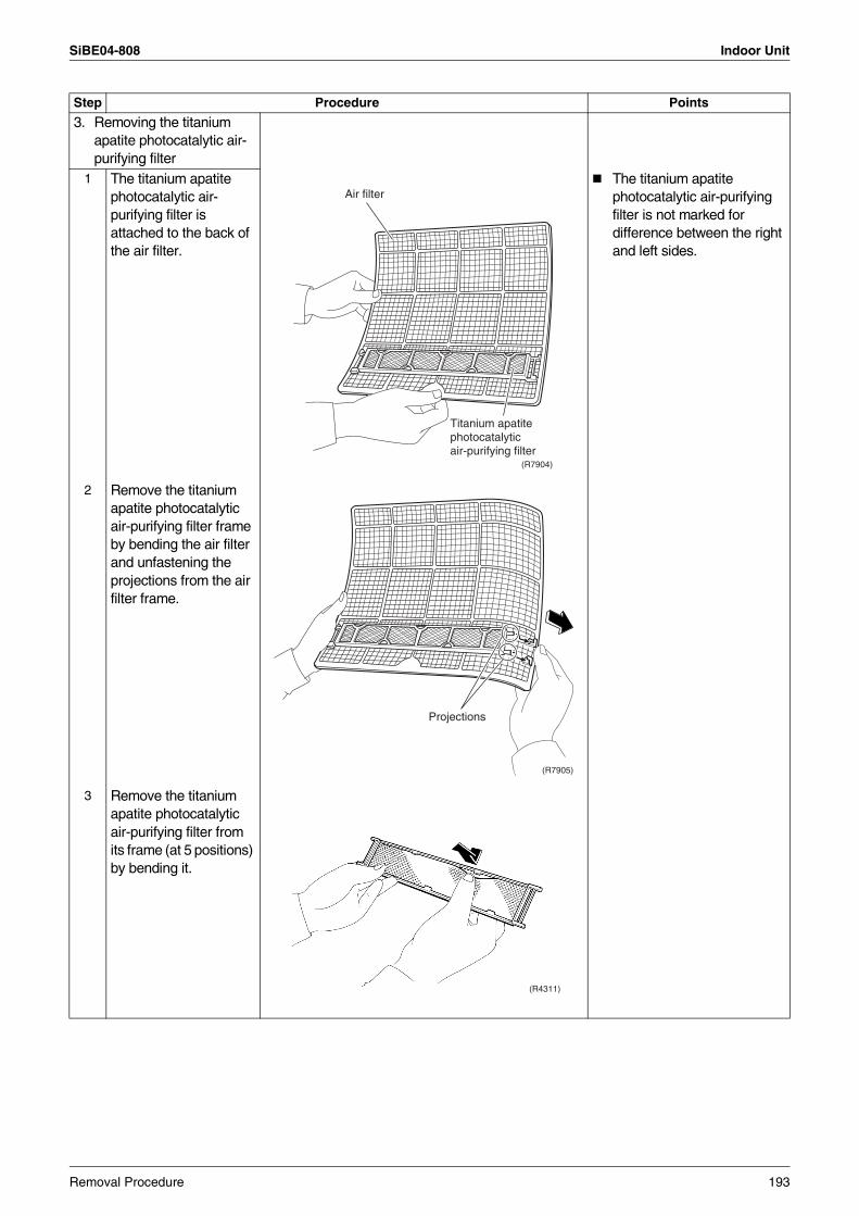
SiBE04-808 Indoor Unit
3. Removing the titanium apatite photocatalytic air-purifying filter
1 The titanium apatite photocatalytic air-purifying filter is attached to the back of the air filter.
The titanium apatite photocatalytic air-purifying filter is not marked for difference between the right and left sides.
2 Remove the titanium apatite photocatalytic air-purifying filter frame by bending the air filter and unfastening the projections from the air filter frame.
3 Remove the titanium apatite photocatalytic air-purifying filter from its frame (at 5 positions) by bending it.
Step Procedure Points
(R7904)
Air filter
Titanium apatitephotocatalyticair-purifying filter
(R7905)
Projections
(R4311)
Removal Procedure 193
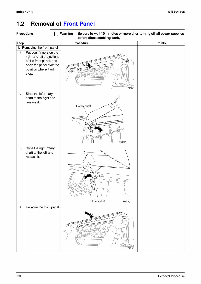
Indoor Unit SiBE04-808
1.2 Removal of Front Panel
Procedure Warning Be sure to wait 10 minutes or more after turning off all power supplies before disassembling work.
Step Procedure Points
1. Removing the front panel1 Put your fingers on the
right and left projections of the front panel, and open the panel over the position where it will stop.
2 Slide the left rotary shaft to the right and release it.
3 Slide the right rotary shaft to the left and release it.
4 Remove the front panel.
(R7906)
(R7907)
Rotary shaft
(R7909)Rotary shaft
(R7910)
194 Removal Procedure
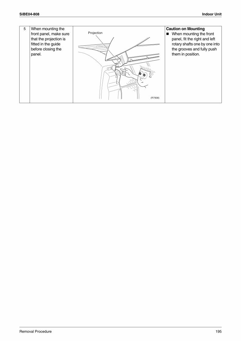
SiBE04-808 Indoor Unit
5 When mounting the front panel, make sure that the projection is fitted in the guide before closing the panel.
Caution on MountingWhen mounting the front panel, fit the right and left rotary shafts one by one into the grooves and fully push them in position.
(R7908)
Projection
Removal Procedure 195
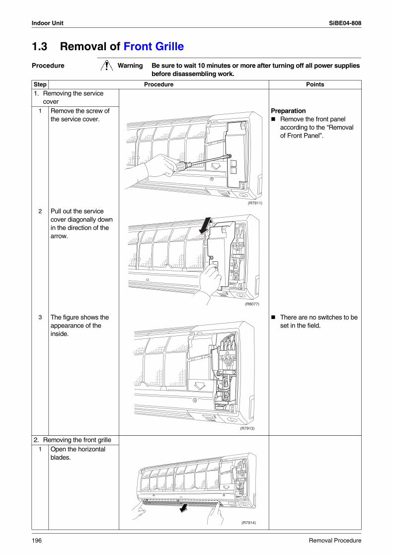
Indoor Unit SiBE04-808
1.3 Removal of Front Grille
Procedure Warning Be sure to wait 10 minutes or more after turning off all power supplies before disassembling work.
Step Procedure Points
1. Removing the service cover
1 Remove the screw of the service cover.
PreparationRemove the front panel according to the “Removal of Front Panel”.
2 Pull out the service cover diagonally down in the direction of the arrow.
3 The figure shows the appearance of the inside.
There are no switches to be set in the field.
2. Removing the front grille1 Open the horizontal
blades.
(R7911)
(R8077)
(R7913)
(R7914)
196 Removal Procedure
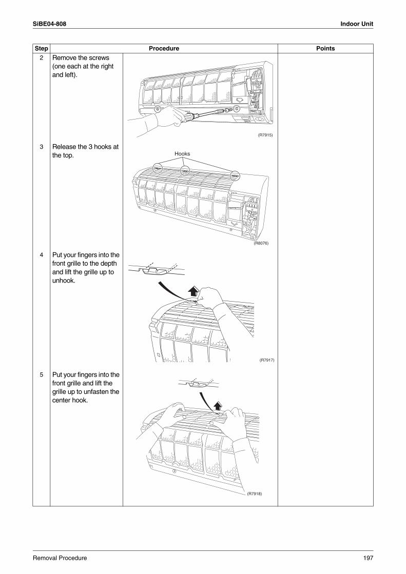
SiBE04-808 Indoor Unit
2 Remove the screws (one each at the right and left).
3 Release the 3 hooks at the top.
4 Put your fingers into the front grille to the depth and lift the grille up to unhook.
5 Put your fingers into the front grille and lift the grille up to unfasten the center hook.
Step Procedure Points
(R7915)
(R8076)
Hooks
(R7917)
(R7918)
Removal Procedure 197
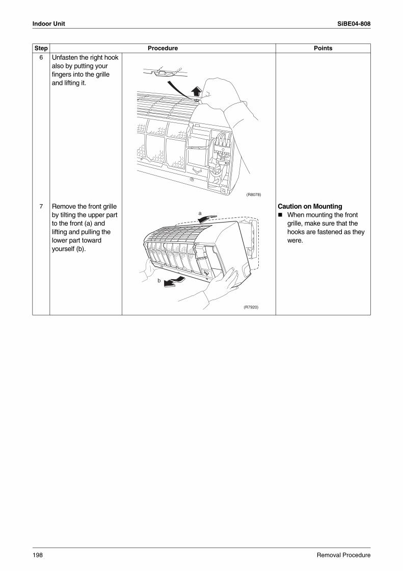
Indoor Unit SiBE04-808
6 Unfasten the right hook also by putting your fingers into the grille and lifting it.
7 Remove the front grille by tilting the upper part to the front (a) and lifting and pulling the lower part toward yourself (b).
Caution on MountingWhen mounting the front grille, make sure that the hooks are fastened as they were.
Step Procedure Points
(R8078)
(R7920)
a
b
198 Removal Procedure
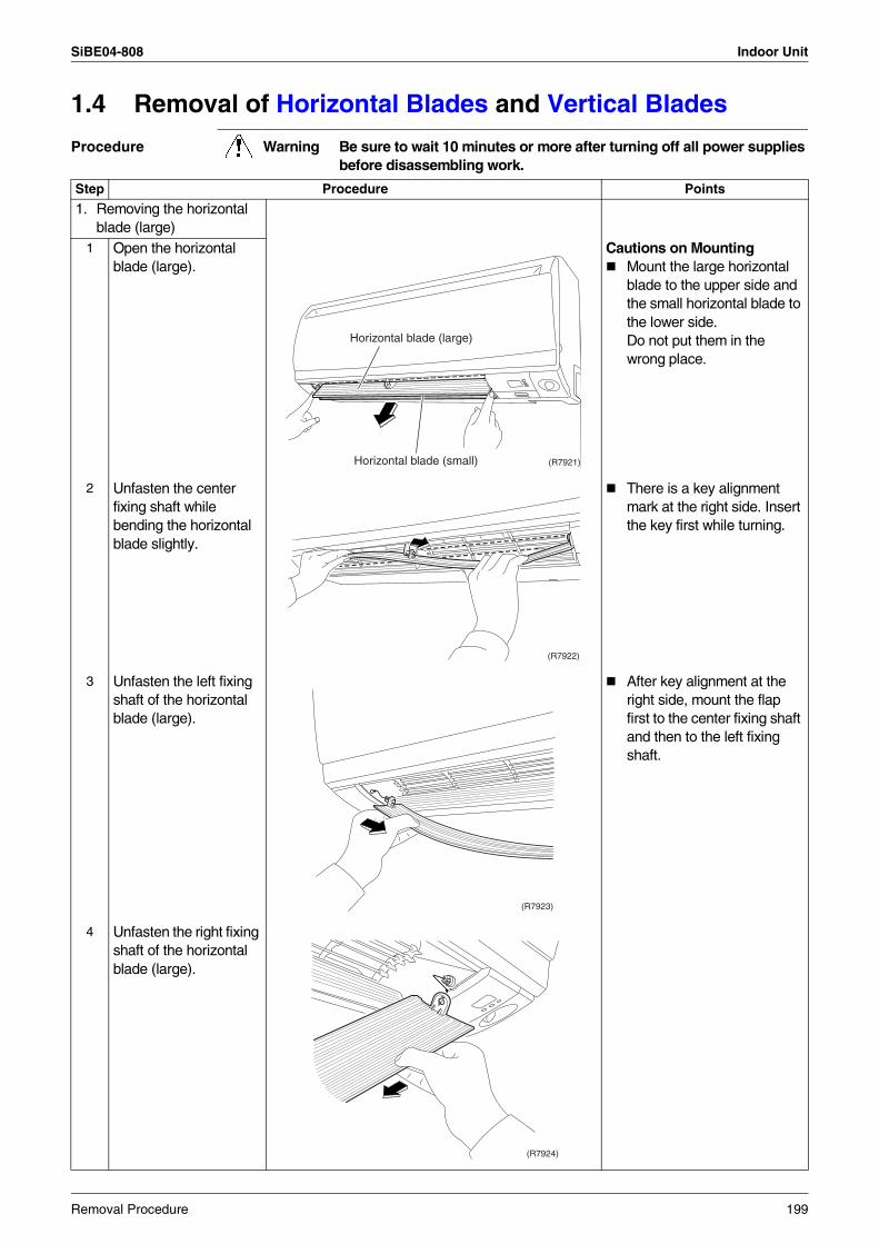
SiBE04-808 Indoor Unit
1.4 Removal of Horizontal Blades and Vertical Blades
Procedure Warning Be sure to wait 10 minutes or more after turning off all power supplies before disassembling work.
Step Procedure Points
1. Removing the horizontal blade (large)
1 Open the horizontal blade (large).
Cautions on MountingMount the large horizontal blade to the upper side and the small horizontal blade to the lower side. Do not put them in the wrong place.
2 Unfasten the center fixing shaft while bending the horizontal blade slightly.
There is a key alignment mark at the right side. Insert the key first while turning.
3 Unfasten the left fixing shaft of the horizontal blade (large).
After key alignment at the right side, mount the flap first to the center fixing shaft and then to the left fixing shaft.
4 Unfasten the right fixing shaft of the horizontal blade (large).
(R7921)
Horizontal blade (large)
Horizontal blade (small)
(R7922)
(R7923)
(R7924)
Removal Procedure 199
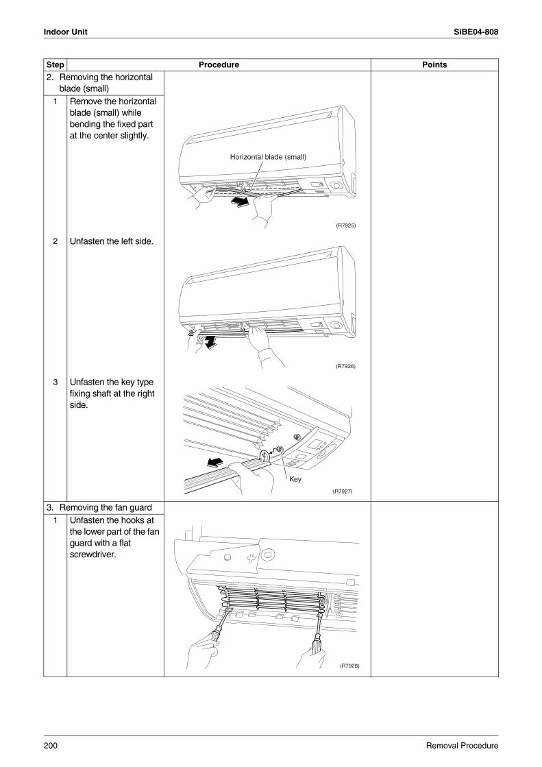
Indoor Unit SiBE04-808
2. Removing the horizontal blade (small)
1 Remove the horizontal blade (small) while bending the fixed part at the center slightly.
2 Unfasten the left side.
3 Unfasten the key type fixing shaft at the right side.
3. Removing the fan guard1 Unfasten the hooks at
the lower part of the fan guard with a flat screwdriver.
Step Procedure Points
(R7925)
Horizontal blade (small)
(R7926)
(R7927)
Key
(R7928)
200 Removal Procedure
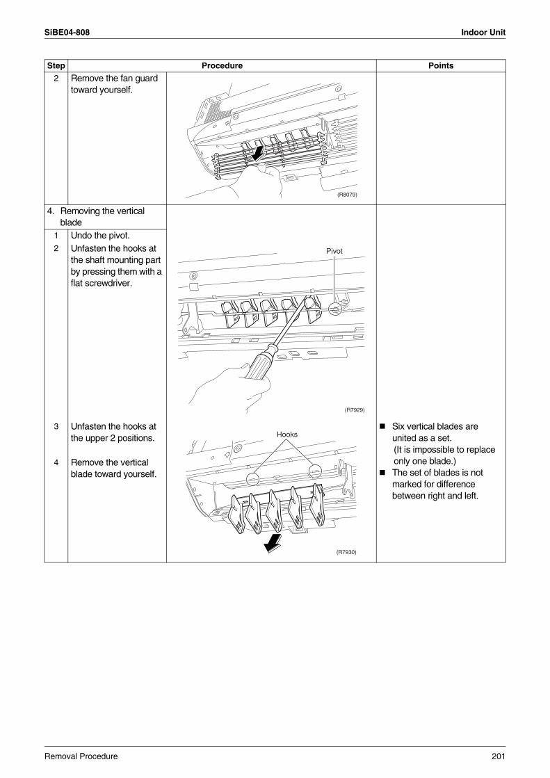
SiBE04-808 Indoor Unit
2 Remove the fan guard toward yourself.
4. Removing the vertical blade
1 Undo the pivot.2 Unfasten the hooks at
the shaft mounting part by pressing them with a flat screwdriver.
3 Unfasten the hooks at the upper 2 positions.
Six vertical blades are united as a set.
(It is impossible to replace only one blade.)
The set of blades is not marked for difference between right and left.
4 Remove the vertical blade toward yourself.
Step Procedure Points
(R8079)
(R7929)
Pivot
(R7930)
Hooks
Removal Procedure 201
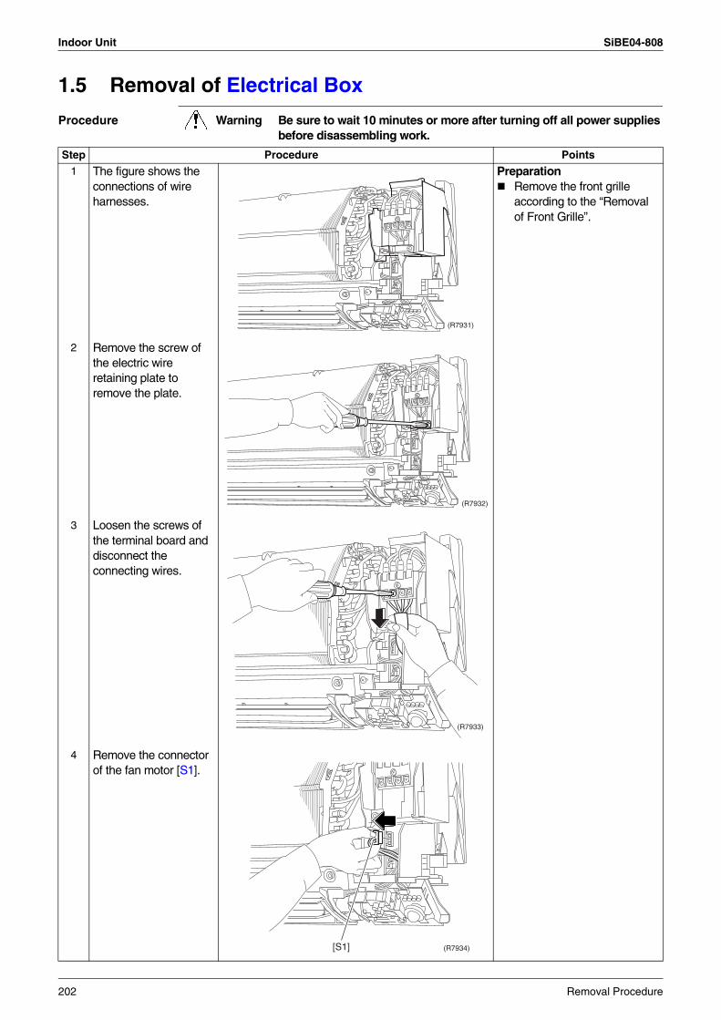
Indoor Unit SiBE04-808
1.5 Removal of Electrical Box
Procedure Warning Be sure to wait 10 minutes or more after turning off all power supplies before disassembling work.
Step Procedure Points
1 The figure shows the connections of wire harnesses.
PreparationRemove the front grille according to the “Removal of Front Grille”.
2 Remove the screw of the electric wire retaining plate to remove the plate.
3 Loosen the screws of the terminal board and disconnect the connecting wires.
4 Remove the connector of the fan motor [S1].
(R7931)
(R7932)
(R7933)
(R7934)[S1]
202 Removal Procedure
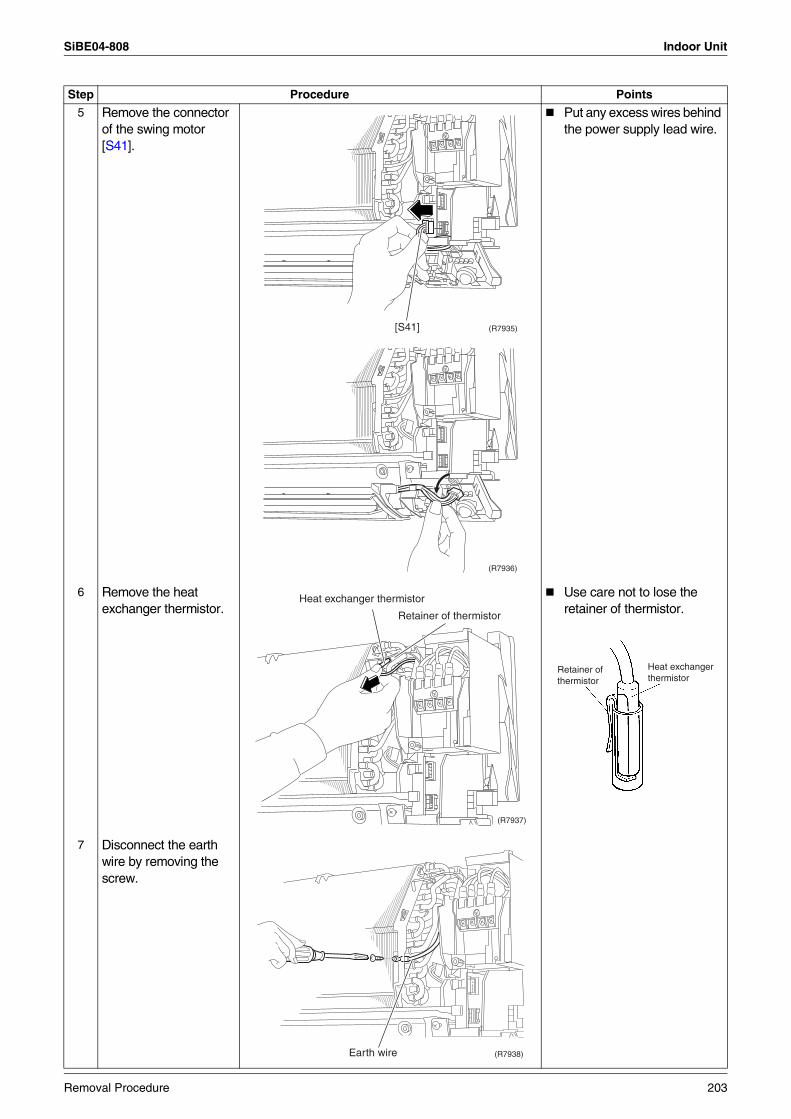
SiBE04-808 Indoor Unit
5 Remove the connector of the swing motor [S41].
Put any excess wires behind the power supply lead wire.
6 Remove the heat exchanger thermistor.
Use care not to lose the retainer of thermistor.
7 Disconnect the earth wire by removing the screw.
Step Procedure Points
(R7935)[S41]
(R7936)
(R7937)
Heat exchanger thermistor
Retainer of thermistor
Retainer of thermistor
Heat exchanger thermistor
(R7938)Earth wire
Removal Procedure 203
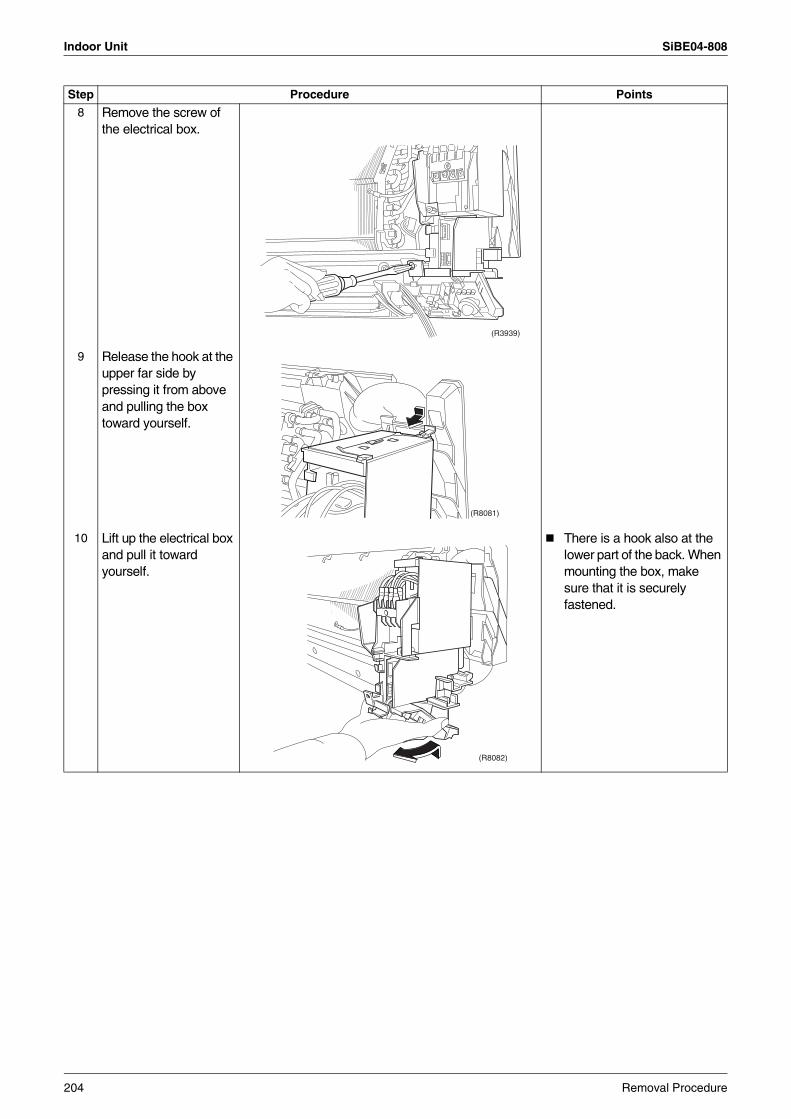
Indoor Unit SiBE04-808
8 Remove the screw of the electrical box.
9 Release the hook at the upper far side by pressing it from above and pulling the box toward yourself.
10 Lift up the electrical box and pull it toward yourself.
There is a hook also at the lower part of the back. When mounting the box, make sure that it is securely fastened.
Step Procedure Points
(R3939)
(R8081)
(R8082)
204 Removal Procedure
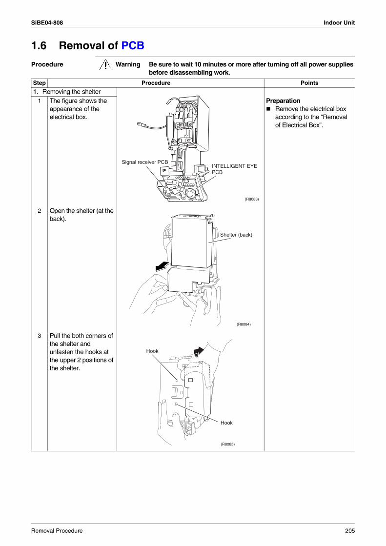
SiBE04-808 Indoor Unit
1.6 Removal of PCB
Procedure Warning Be sure to wait 10 minutes or more after turning off all power supplies before disassembling work.
Step Procedure Points
1. Removing the shelter1 The figure shows the
appearance of the electrical box.
PreparationRemove the electrical box according to the “Removal of Electrical Box”.
2 Open the shelter (at the back).
3 Pull the both corners of the shelter and unfasten the hooks at the upper 2 positions of the shelter.
(R8083)
Signal receiver PCBINTELLIGENT EYEPCB
(R8084)
Shelter (back)
(R8085)
Hook
Hook
Removal Procedure 205
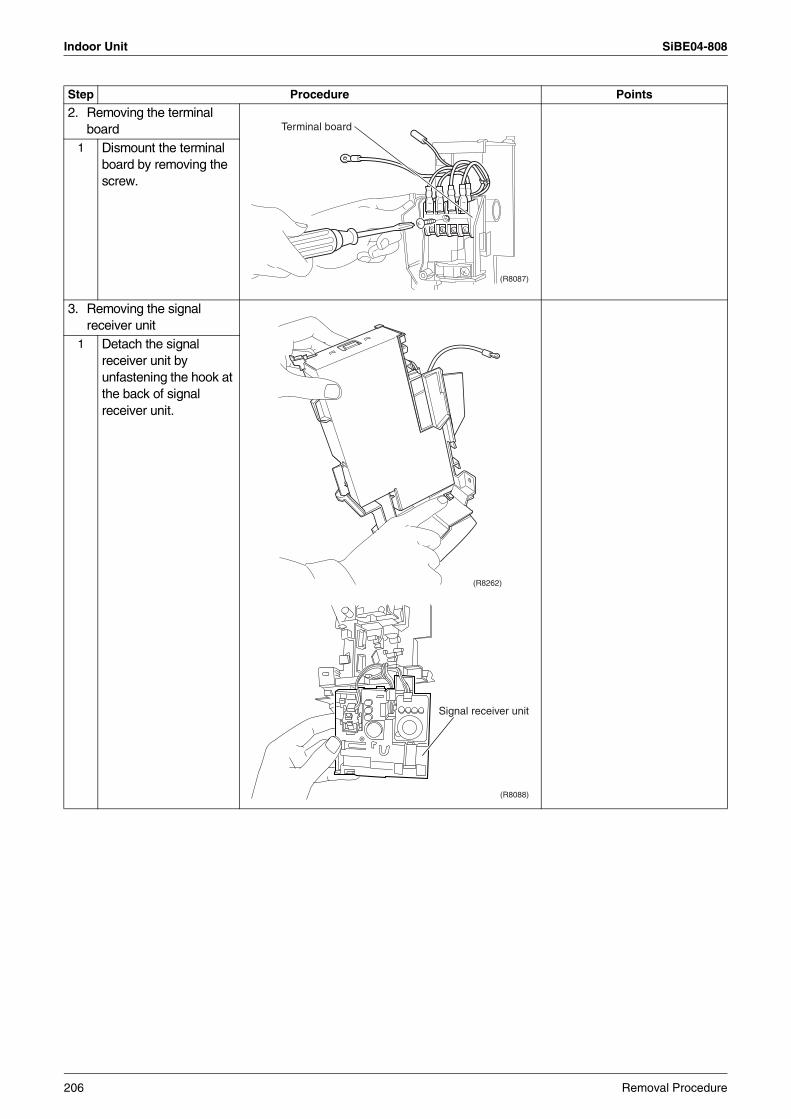
Indoor Unit SiBE04-808
2. Removing the terminal board
1 Dismount the terminal board by removing the screw.
3. Removing the signal receiver unit
1 Detach the signal receiver unit by unfastening the hook at the back of signal receiver unit.
Step Procedure Points
(R8087)
Terminal board
(R8262)
(R8088)
Signal receiver unit
206 Removal Procedure
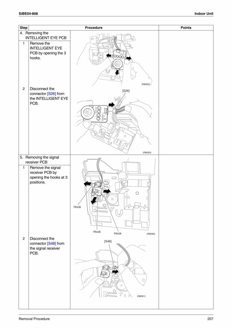
SiBE04-808 Indoor Unit
4. Removing the INTELLIGENT EYE PCB
1 Remove the INTELLIGENT EYE PCB by opening the 3 hooks.
2 Disconnect the connector [S26] from the INTELLIGENT EYE PCB.
5. Removing the signal receiver PCB
1 Remove the signal receiver PCB by opening the hooks at 3 positions.
2 Disconnect the connector [S48] from the signal receiver PCB.
Step Procedure Points
(R8092)
(R8093)
[S26]
(R8090)
Hook
Hook Hook
(R8091)
[S48]
Removal Procedure 207
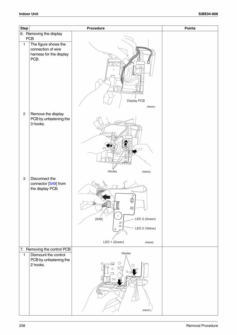
Indoor Unit SiBE04-808
6. Removing the display PCB
1 The figure shows the connection of wire harness for the display PCB.
2 Remove the display PCB by unfastening the 3 hooks.
3 Disconnect the connector [S49] from the display PCB.
7. Removing the control PCB1 Dismount the control
PCB by unfastening the 2 hooks.
Step Procedure Points
(R8094)
Display PCB
(R8095)Hooks
(R8096)
LED 3 (Green)
LED 1 (Green)
[S49]
LED 2 (Yellow)
(R8097)
Hooks
208 Removal Procedure
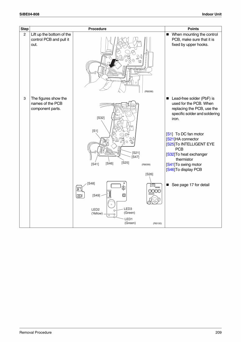
SiBE04-808 Indoor Unit
2 Lift up the bottom of the control PCB and pull it out.
When mounting the control PCB, make sure that it is fixed by upper hooks.
3 The figures show the names of the PCB component parts.
Lead-free solder (PbF) is used for the PCB. When replacing the PCB, use the specific solder and soldering iron.
[S1] To DC fan motor[S21]HA connector[S25]To INTELLIGENT EYE
PCB[S32]To heat exchanger
thermistor[S41]To swing motor[S46]To display PCB
See page 17 for detail
Step Procedure Points
(R8098)
(R8099)
[S32]
[S1]
[S21][S47]
[S25][S46][S41]
(R8100)
[S48]
[S49]
[S26]
LED3(Green)
LED1(Green)
LED2(Yellow)
Removal Procedure 209
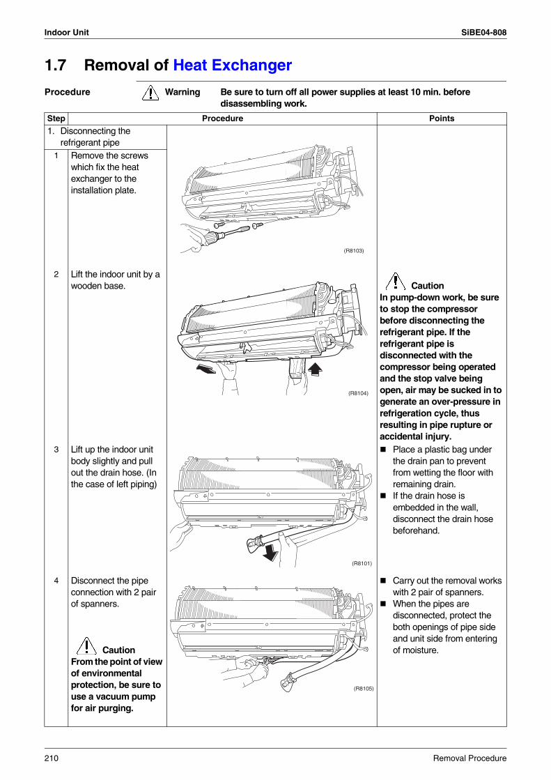
Indoor Unit SiBE04-808
1.7 Removal of Heat Exchanger
Procedure Warning Be sure to turn off all power supplies at least 10 min. before disassembling work.
Step Procedure Points
1. Disconnecting the refrigerant pipe
1 Remove the screws which fix the heat exchanger to the installation plate.
2 Lift the indoor unit by a wooden base.
Caution
In pump-down work, be sure to stop the compressor before disconnecting the refrigerant pipe. If the refrigerant pipe is disconnected with the compressor being operated and the stop valve being open, air may be sucked in to generate an over-pressure in refrigeration cycle, thus resulting in pipe rupture or accidental injury.
3 Lift up the indoor unit body slightly and pull out the drain hose. (In the case of left piping)
Place a plastic bag under the drain pan to prevent from wetting the floor with remaining drain.If the drain hose is embedded in the wall, disconnect the drain hose beforehand.
4 Disconnect the pipe connection with 2 pair of spanners.
CautionFrom the point of view of environmental protection, be sure to use a vacuum pump for air purging.
Carry out the removal works with 2 pair of spanners.When the pipes are disconnected, protect the both openings of pipe side and unit side from entering of moisture.
(R8103)
(R8104)
(R8101)
(R8105)
210 Removal Procedure
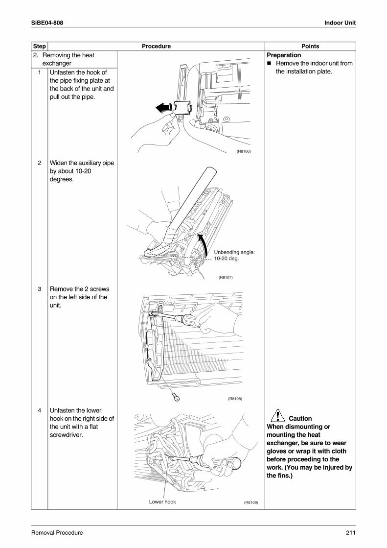
SiBE04-808 Indoor Unit
2. Removing the heat exchanger
PreparationRemove the indoor unit from the installation plate.1 Unfasten the hook of
the pipe fixing plate at the back of the unit and pull out the pipe.
2 Widen the auxiliary pipe by about 10-20 degrees.
3 Remove the 2 screws on the left side of the unit.
4 Unfasten the lower hook on the right side of the unit with a flat screwdriver.
Caution
When dismounting or mounting the heat exchanger, be sure to wear gloves or wrap it with cloth before proceeding to the work. (You may be injured by the fins.)
Step Procedure Points
(R8106)
(R8107)
Unbending angle:10-20 deg.
(R8108)
(R8109)Lower hook
Removal Procedure 211
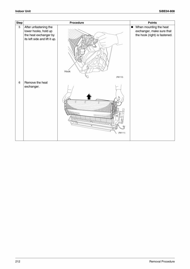
Indoor Unit SiBE04-808
5 After unfastening the lower hooks, hold up the heat exchanger by its left side and lift it up.
When mounting the heat exchanger, make sure that the hook (right) is fastened.
6 Remove the heat exchanger.
Step Procedure Points
(R8110)
Hook
(R8111)
212 Removal Procedure
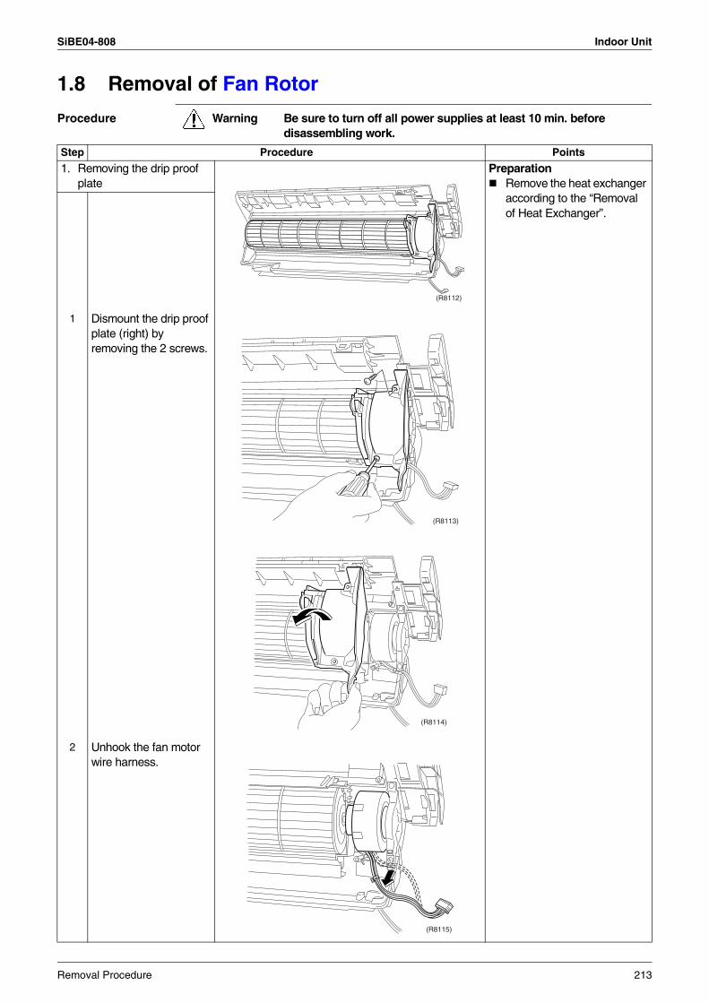
SiBE04-808 Indoor Unit
1.8 Removal of Fan Rotor
Procedure Warning Be sure to turn off all power supplies at least 10 min. before disassembling work.
Step Procedure Points
1. Removing the drip proof plate
PreparationRemove the heat exchanger according to the “Removal of Heat Exchanger”.
1 Dismount the drip proof plate (right) by removing the 2 screws.
2 Unhook the fan motor wire harness.
(R8112)
(R8113)
(R8114)
(R8115)
Removal Procedure 213
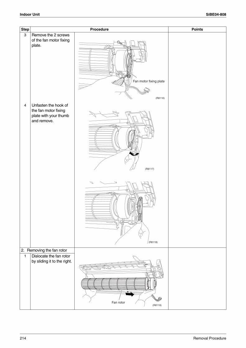
Indoor Unit SiBE04-808
3 Remove the 2 screws of the fan motor fixing plate.
4 Unfasten the hook of the fan motor fixing plate with your thumb and remove.
2. Removing the fan rotor1 Dislocate the fan rotor
by sliding it to the right.
Step Procedure Points
(R8116)
Fan motor fixing plate
(R8117)
(R8118)
(R8119)Fan rotor
214 Removal Procedure
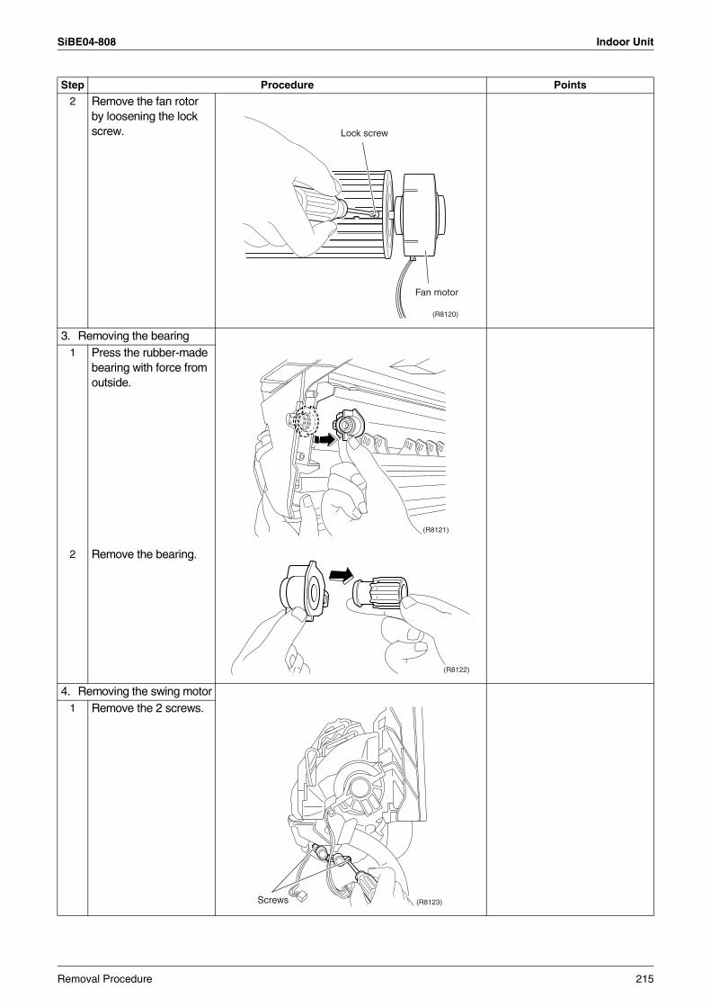
SiBE04-808 Indoor Unit
2 Remove the fan rotor by loosening the lock screw.
3. Removing the bearing1 Press the rubber-made
bearing with force from outside.
2 Remove the bearing.
4. Removing the swing motor1 Remove the 2 screws.
Step Procedure Points
(R8120)
Lock screw
Fan motor
(R8121)
(R8122)
(R8123)Screws
Removal Procedure 215
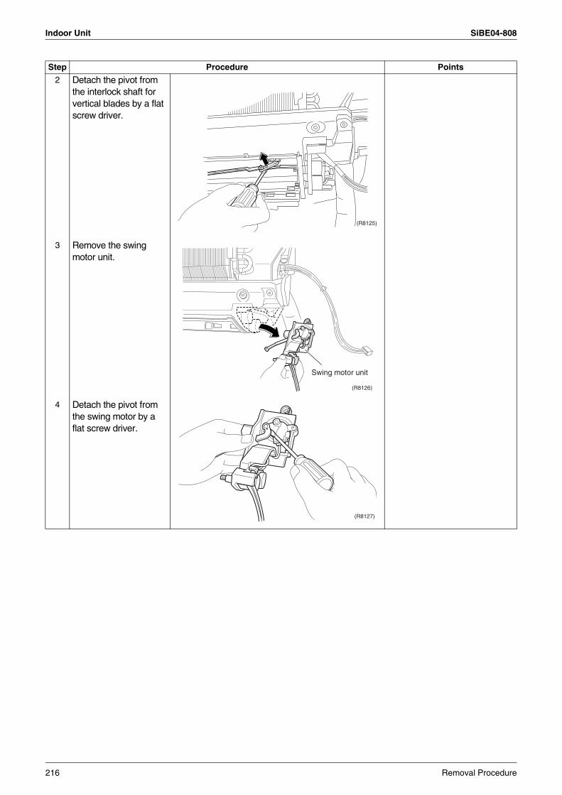
Indoor Unit SiBE04-808
2 Detach the pivot from the interlock shaft for vertical blades by a flat screw driver.
3 Remove the swing motor unit.
4 Detach the pivot from the swing motor by a flat screw driver.
Step Procedure Points
(R8125)
(R8126)
Swing motor unit
(R8127)
216 Removal Procedure
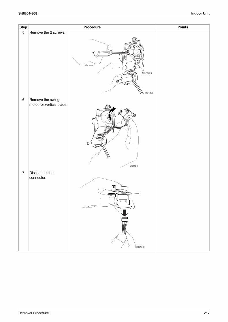
SiBE04-808 Indoor Unit
5 Remove the 2 screws.
6 Remove the swing motor for vertical blade.
7 Disconnect the connector.
Step Procedure Points
(R8128)
Screws
(R8129)
(R8130)
Removal Procedure 217
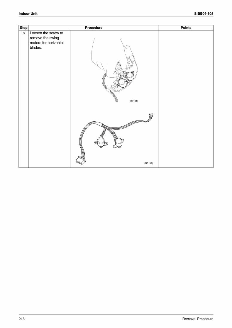
Indoor Unit SiBE04-808
8 Loosen the screw to remove the swing motors for horizontal blades.
Step Procedure Points
(R8131)
(R8132)
218 Removal Procedure
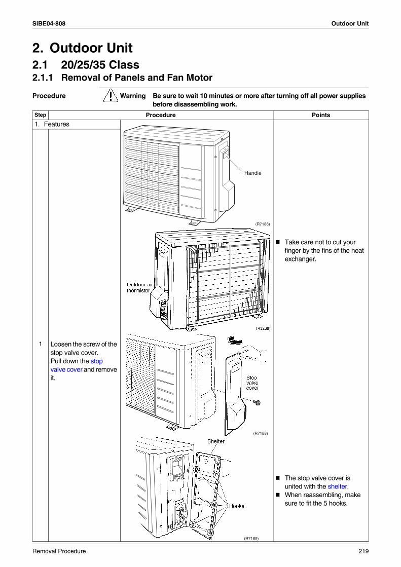
SiBE04-808 Outdoor Unit
2. Outdoor Unit2.1 20/25/35 Class2.1.1 Removal of Panels and Fan Motor
Procedure Warning Be sure to wait 10 minutes or more after turning off all power supplies before disassembling work.
Step Procedure Points
1. Features
Take care not to cut your finger by the fins of the heat exchanger.
The stop valve cover is united with the shelter.When reassembling, make sure to fit the 5 hooks.
1 Loosen the screw of the stop valve cover.Pull down the stop valve cover and remove it.
DAIKININVERTER
(R7186)
Handle
(R7188)
(R7189)
Removal Procedure 219
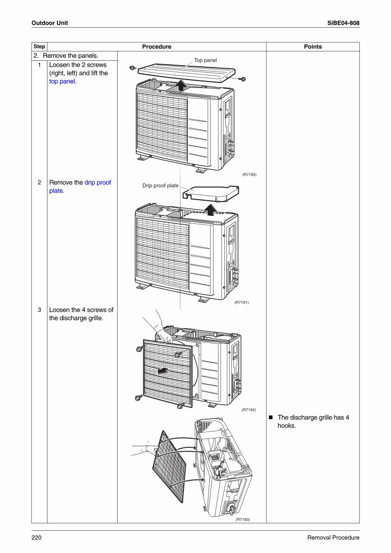
Outdoor Unit SiBE04-808
2. Remove the panels.1 Loosen the 2 screws
(right, left) and lift the top panel.
2 Remove the drip proof plate.
3 Loosen the 4 screws of the discharge grille.
The discharge grille has 4 hooks.
Step Procedure Points
DAIKININVERTER
Top panel
(R7190)
DAIKININVERTER
(R7191)
Drip proof plate
DAIKININVERTER
(R7192)
(R7193)
220 Removal Procedure
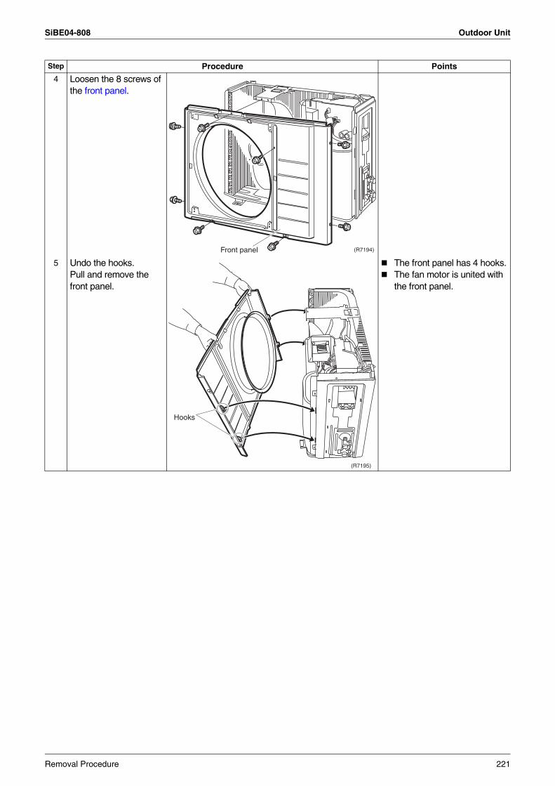
SiBE04-808 Outdoor Unit
4 Loosen the 8 screws of the front panel.
5 Undo the hooks.Pull and remove the front panel.
The front panel has 4 hooks.The fan motor is united with the front panel.
Step Procedure Points
DAIKININVERTER
(R7194)Front panel
(R7195)
Hooks
Removal Procedure 221
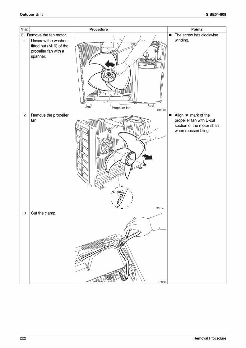
Outdoor Unit SiBE04-808
3. Remove the fan motor. The screw has clockwise winding.1 Unscrew the washer-
fitted nut (M10) of the propeller fan with a spanner.
2 Remove the propeller fan.
Align mark of the propeller fan with D-cut section of the motor shaft when reassembling.
3 Cut the clamp.
Step Procedure Points
(R7196)Propeller fan
D-cut
(R7197)
(R7198)
222 Removal Procedure
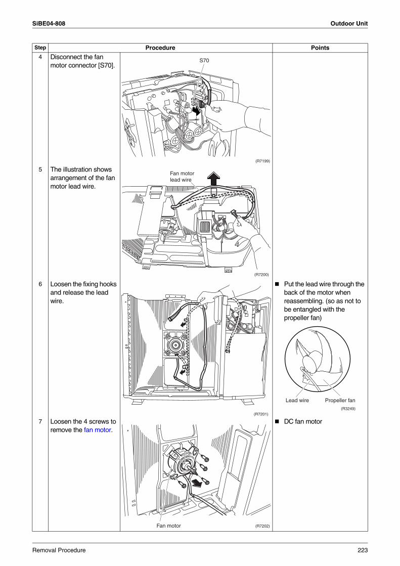
SiBE04-808 Outdoor Unit
4 Disconnect the fan motor connector [S70].
5 The illustration shows arrangement of the fan motor lead wire.
6 Loosen the fixing hooks and release the lead wire.
Put the lead wire through the back of the motor when reassembling. (so as not to be entangled with the propeller fan)
7 Loosen the 4 screws to remove the fan motor.
DC fan motor
Step Procedure Points
S70
(R7199)
Fan motor lead wire
(R7200)
(R7201)(R3249)
Lead wire Propeller fan
Fan motor (R7202)
Removal Procedure 223
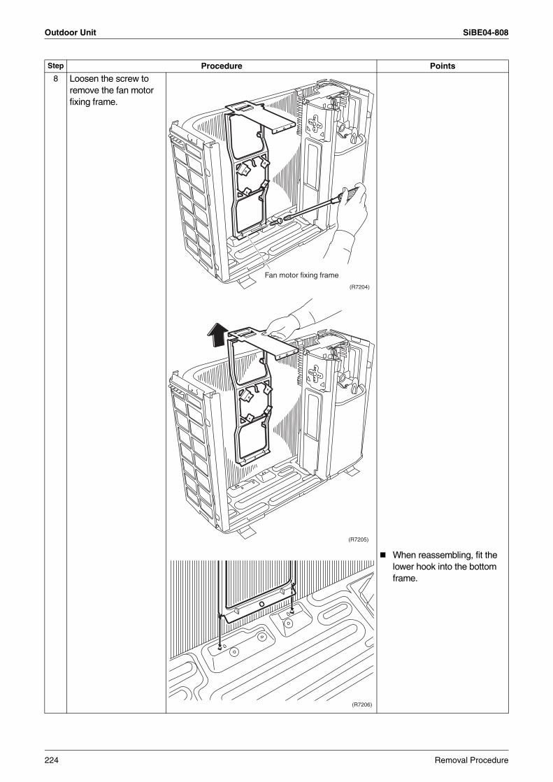
Outdoor Unit SiBE04-808
8 Loosen the screw to remove the fan motor fixing frame.
When reassembling, fit the lower hook into the bottom frame.
Step Procedure Points
(R7204)
Fan motor fixing frame
(R7205)
(R7206)
224 Removal Procedure
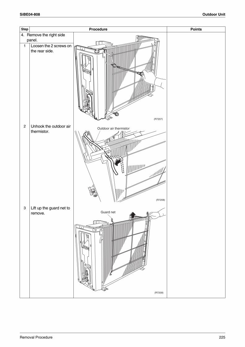
SiBE04-808 Outdoor Unit
4. Remove the right side panel.
1 Loosen the 2 screws on the rear side.
2 Unhook the outdoor air thermistor.
3 Lift up the guard net to remove.
Step Procedure Points
(R7207)
(R7208)
Outdoor air thermistor
Guard net
(R7209)
Removal Procedure 225
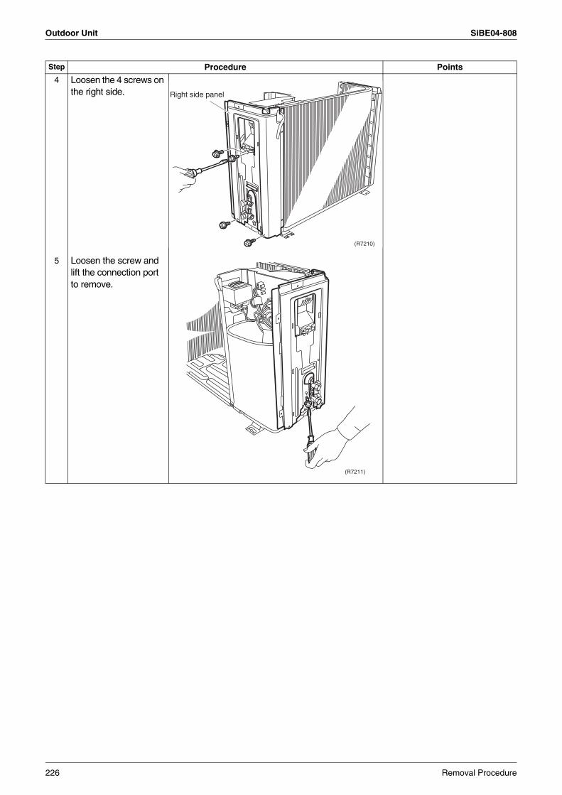
Outdoor Unit SiBE04-808
4 Loosen the 4 screws on the right side.
5 Loosen the screw and lift the connection port to remove.
Step Procedure Points
(R7210)
Right side panel
(R7211)
226 Removal Procedure
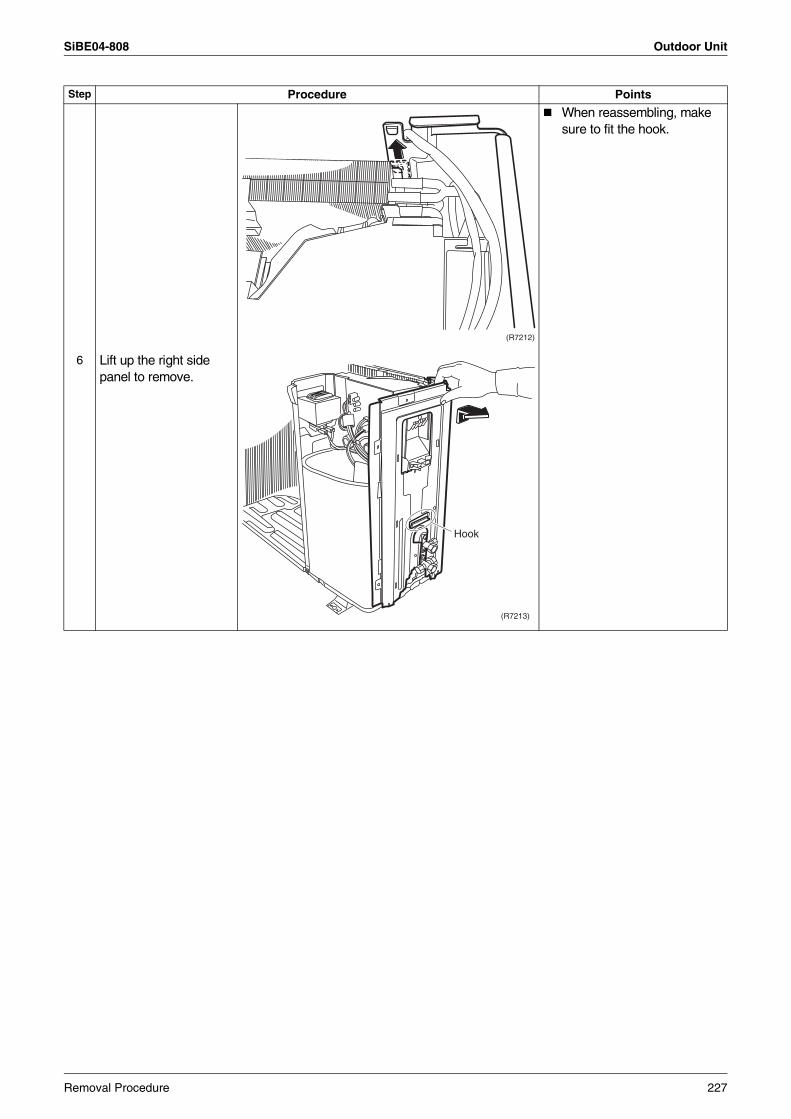
SiBE04-808 Outdoor Unit
When reassembling, make sure to fit the hook.
6 Lift up the right side panel to remove.
Step Procedure Points
(R7212)
(R7213)
Hook
Removal Procedure 227
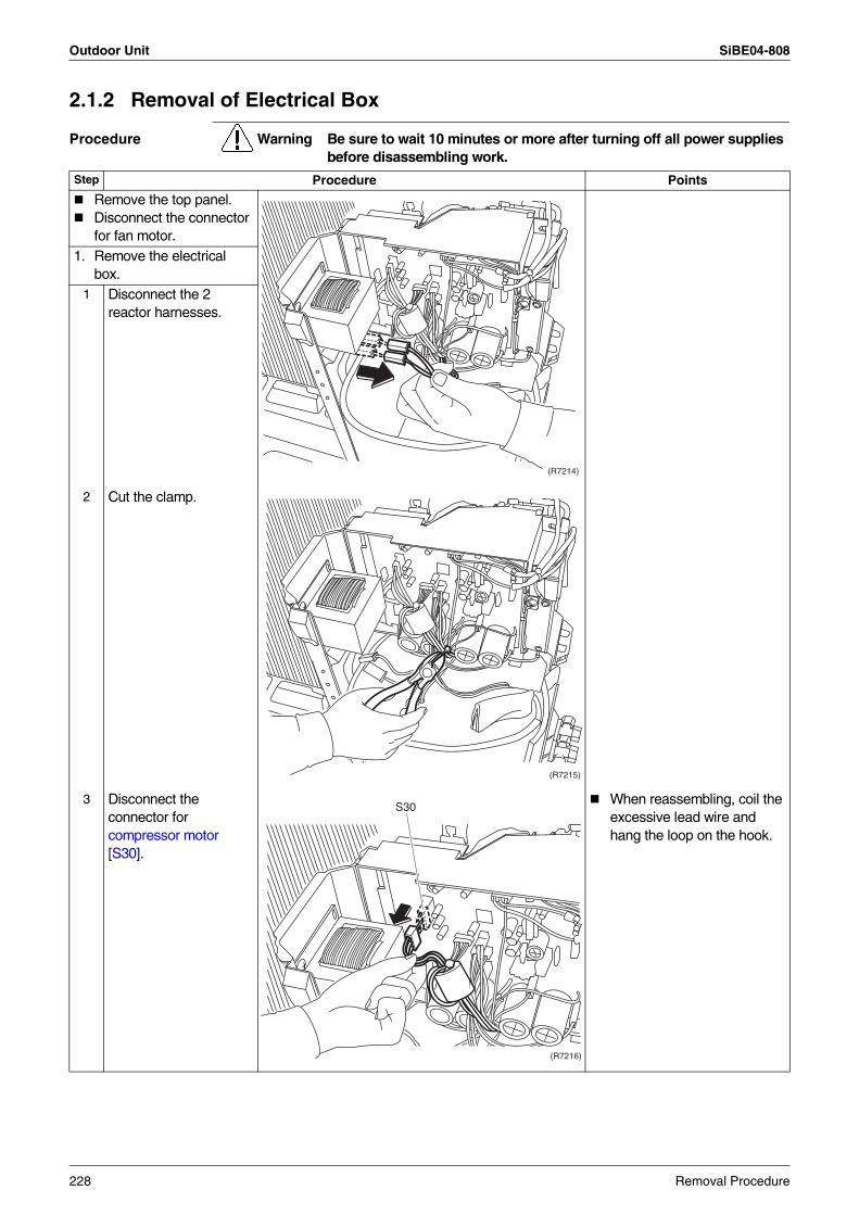
Outdoor Unit SiBE04-808
2.1.2 Removal of Electrical Box
Procedure Warning Be sure to wait 10 minutes or more after turning off all power supplies before disassembling work.
Step Procedure Points
Remove the top panel.Disconnect the connector for fan motor.
1. Remove the electrical box.
1 Disconnect the 2 reactor harnesses.
2 Cut the clamp.
3 Disconnect the connector for compressor motor [S30].
When reassembling, coil the excessive lead wire and hang the loop on the hook.
(R7214)
(R7215)
(R7216)
S30
228 Removal Procedure

SiBE04-808 Outdoor Unit
4 Disconnect the connector for overload protector [S40].
The positions of connectors on PCB are different according to the models.
5 Disconnect the connector for electronic expansion valve coil [S20].
6 Disconnect the connector for four way valve coil [S80].
Step Procedure Points
(R7217)
S40
(R7218)
S20
(R7219)S80
Removal Procedure 229
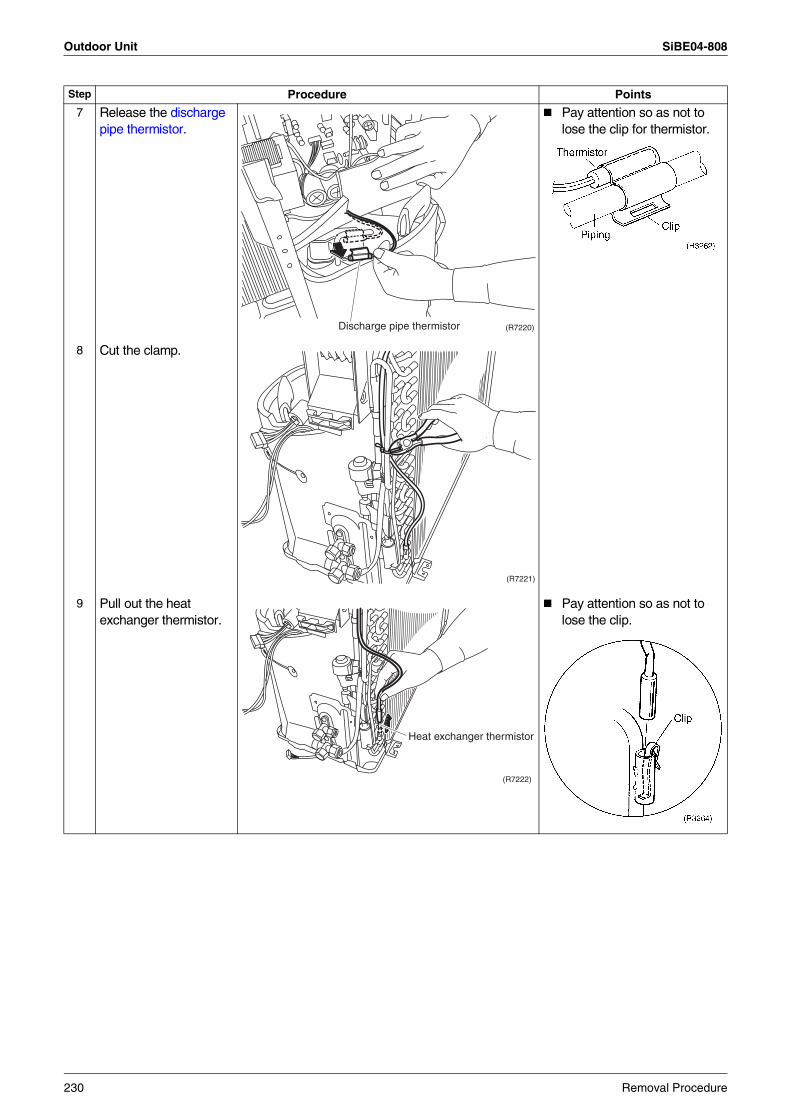
Outdoor Unit SiBE04-808
7 Release the discharge pipe thermistor.
Pay attention so as not to lose the clip for thermistor.
8 Cut the clamp.
9 Pull out the heat exchanger thermistor.
Pay attention so as not to lose the clip.
Step Procedure Points
(R7220)Discharge pipe thermistor
(R7221)
(R7222)
Heat exchanger thermistor
230 Removal Procedure
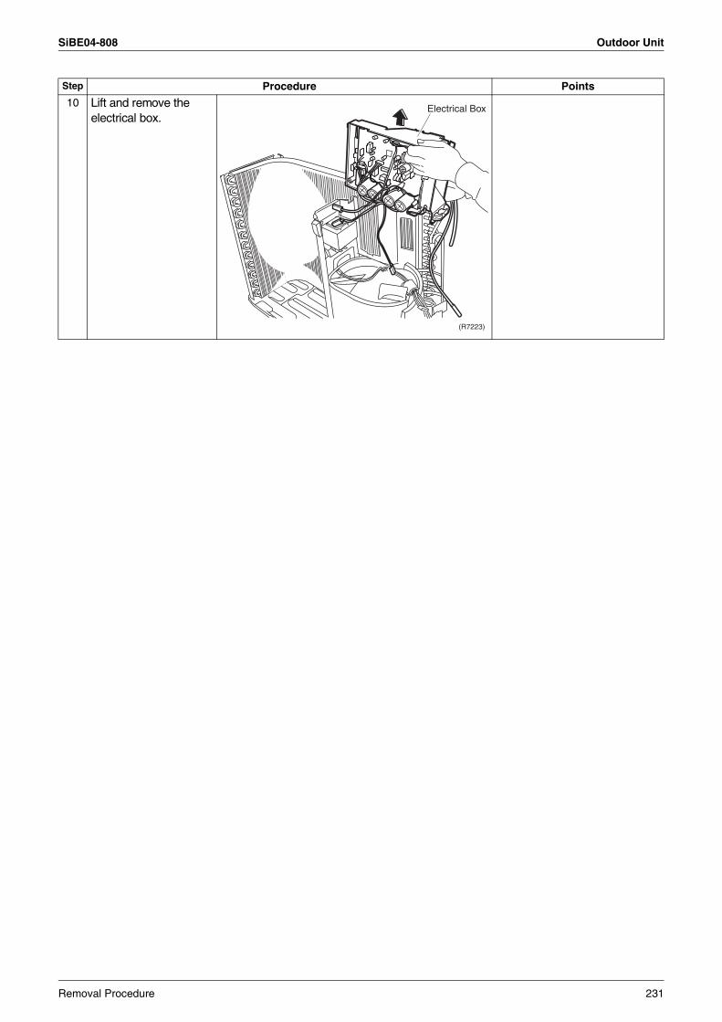
SiBE04-808 Outdoor Unit
10 Lift and remove the electrical box.
Step Procedure Points
(R7223)
Electrical Box
Removal Procedure 231
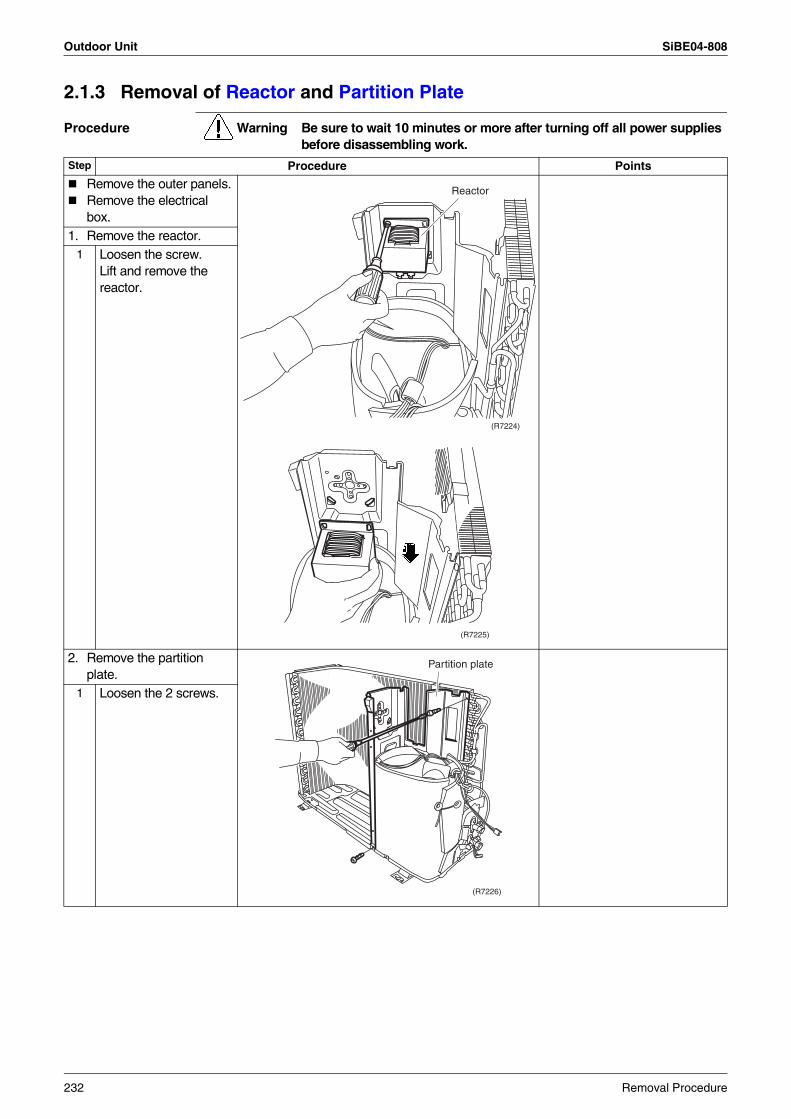
Outdoor Unit SiBE04-808
2.1.3 Removal of Reactor and Partition Plate
Procedure Warning Be sure to wait 10 minutes or more after turning off all power supplies before disassembling work.
Step Procedure Points
Remove the outer panels.Remove the electrical box.
1. Remove the reactor.1 Loosen the screw.
Lift and remove the reactor.
2. Remove the partition plate.
1 Loosen the 2 screws.
(R7224)
Reactor
(R7225)
(R7226)
Partition plate
232 Removal Procedure
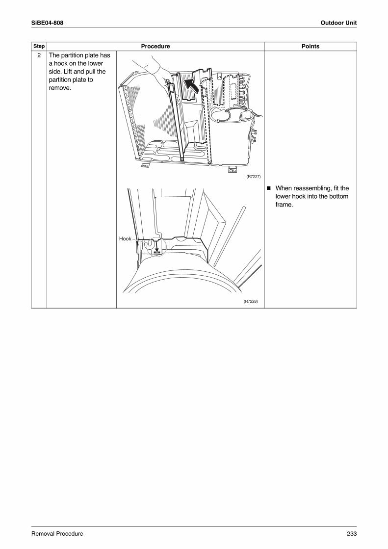
SiBE04-808 Outdoor Unit
2 The partition plate has a hook on the lower side. Lift and pull the partition plate to remove.
When reassembling, fit the lower hook into the bottom frame.
Step Procedure Points
(R7227)
(R7228)
Hook
Removal Procedure 233
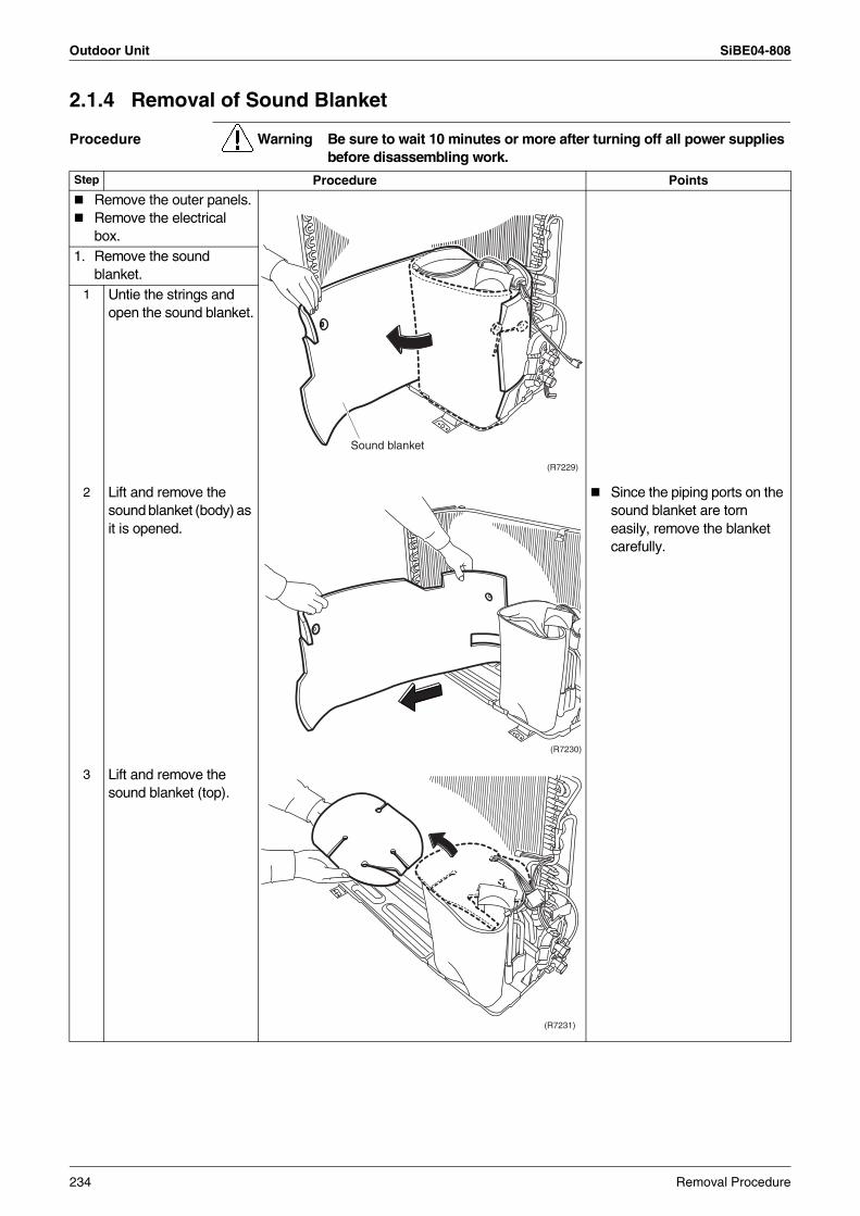
Outdoor Unit SiBE04-808
2.1.4 Removal of Sound Blanket
Procedure Warning Be sure to wait 10 minutes or more after turning off all power supplies before disassembling work.
Step Procedure Points
Remove the outer panels.Remove the electrical box.
1. Remove the sound blanket.
1 Untie the strings and open the sound blanket.
2 Lift and remove the sound blanket (body) as it is opened.
Since the piping ports on the sound blanket are torn easily, remove the blanket carefully.
3 Lift and remove the sound blanket (top).
(R7229)
Sound blanket
(R7230)
(R7231)
234 Removal Procedure
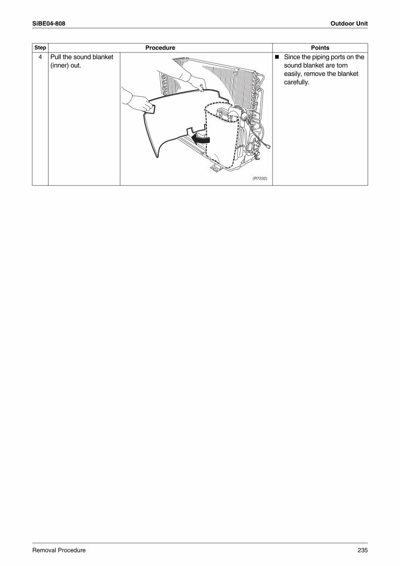
SiBE04-808 Outdoor Unit
4 Pull the sound blanket (inner) out.
Since the piping ports on the sound blanket are torn easily, remove the blanket carefully.
Step Procedure Points
(R7232)
Removal Procedure 235
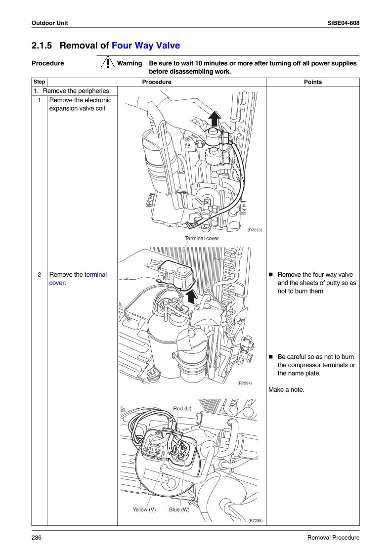
Outdoor Unit SiBE04-808
2.1.5 Removal of Four Way Valve
Procedure Warning Be sure to wait 10 minutes or more after turning off all power supplies before disassembling work.
Step Procedure Points
1. Remove the peripheries.1 Remove the electronic
expansion valve coil.
2 Remove the terminal cover.
Remove the four way valve and the sheets of putty so as not to burn them.
Be careful so as not to burn the compressor terminals or the name plate.
Make a note.
(R7233)
(R7234)
Terminal cover
VW
U
(R7235)
Red (U)
Yellow (V) Blue (W)
236 Removal Procedure
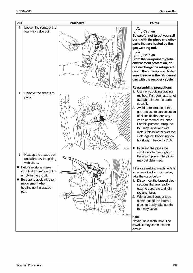
SiBE04-808 Outdoor Unit
3 Loosen the screw of the four way valve coil. Caution
Be careful not to get yourself burnt with the pipes and other parts that are heated by the gas welding rod.
CautionFrom the viewpoint of global environment protection, do not discharge the refrigerant gas in the atmosphere. Make sure to recover the refrigerant gas with the recovery system.
Reassembling precautions1. Use non-oxidizing brazing
method. If nitrogen gas is not available, braze the parts speedily.
2. Avoid deterioration of the gaskets due to carbonization of oil inside the four way valve or thermal influence. For this purpose, wrap the four way valve with wet cloth. Splash water over the cloth against becoming too hot (keep it below 120°C).
In pulling the pipes, be careful not to over-tighten them with pliers. The pipes may get deformed.
If the gas welding machine fails to remove the four way valve, take the steps below.1. Disconnect the brazed pipe
sections that are readily easy to separate and join together later.
2. With a small copper tube cutter, cut off the internal pipes to easily take out the four way valve.
Note:Never use a metal saw. The sawdust may come into the circuit.
4 Remove the sheets of putty.
5 Heat up the brazed part and withdraw the piping with pliers.
Before working, make sure that the refrigerant is empty in the circuit.Be sure to apply nitrogen replacement when heating up the brazed part.
Step Procedure Points
(R7247)
(R7248)
(R7249)
Removal Procedure 237
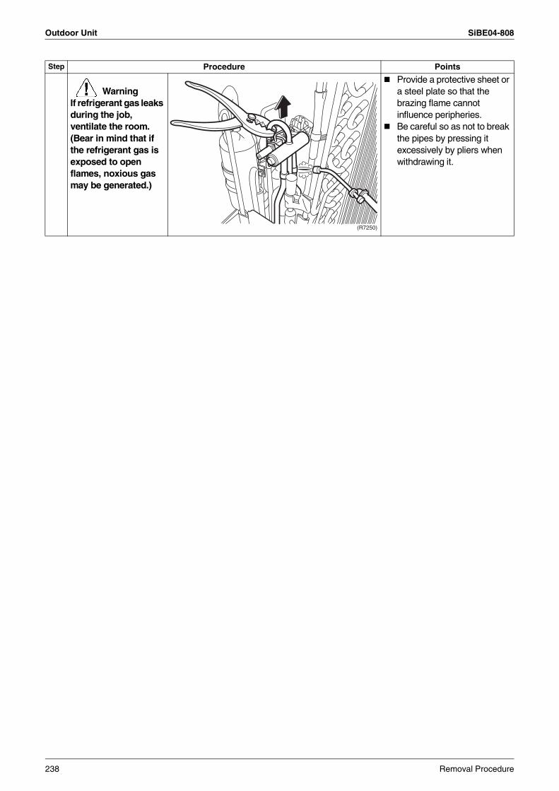
Outdoor Unit SiBE04-808
WarningIf refrigerant gas leaks during the job, ventilate the room. (Bear in mind that if the refrigerant gas is exposed to open flames, noxious gas may be generated.)
Provide a protective sheet or a steel plate so that the brazing flame cannot influence peripheries.Be careful so as not to break the pipes by pressing it excessively by pliers when withdrawing it.
Step Procedure Points
(R7250)
238 Removal Procedure
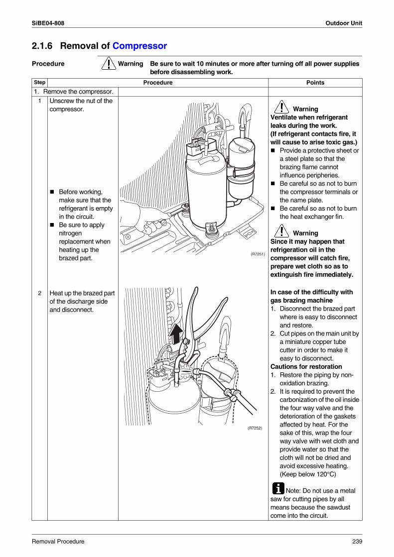
SiBE04-808 Outdoor Unit
2.1.6 Removal of Compressor
Procedure Warning Be sure to wait 10 minutes or more after turning off all power supplies before disassembling work.
Step Procedure Points
1. Remove the compressor.1 Unscrew the nut of the
compressor.
Before working, make sure that the refrigerant is empty in the circuit.Be sure to apply nitrogen replacement when heating up the brazed part.
WarningVentilate when refrigerant leaks during the work.(If refrigerant contacts fire, it will cause to arise toxic gas.)
Provide a protective sheet or a steel plate so that the brazing flame cannot influence peripheries.Be careful so as not to burn the compressor terminals or the name plate.Be careful so as not to burn the heat exchanger fin.
WarningSince it may happen that refrigeration oil in the compressor will catch fire, prepare wet cloth so as to extinguish fire immediately.
In case of the difficulty with gas brazing machine 1. Disconnect the brazed part
where is easy to disconnect and restore.
2. Cut pipes on the main unit by a miniature copper tube cutter in order to make it easy to disconnect.
Cautions for restoration1. Restore the piping by non-
oxidation brazing. 2. It is required to prevent the
carbonization of the oil inside the four way valve and the deterioration of the gaskets affected by heat. For the sake of this, wrap the four way valve with wet cloth and provide water so that the cloth will not be dried and avoid excessive heating. (Keep below 120°C)
Note: Do not use a metal saw for cutting pipes by all means because the sawdust come into the circuit.
2 Heat up the brazed part of the discharge side and disconnect.
(R7251)
(R7252)
Removal Procedure 239
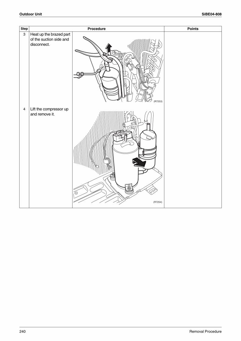
Outdoor Unit SiBE04-808
Step Procedure Points
3 Heat up the brazed part of the suction side and disconnect.
4 Lift the compressor up and remove it.
(R7253)
(R7254)
240 Removal Procedure
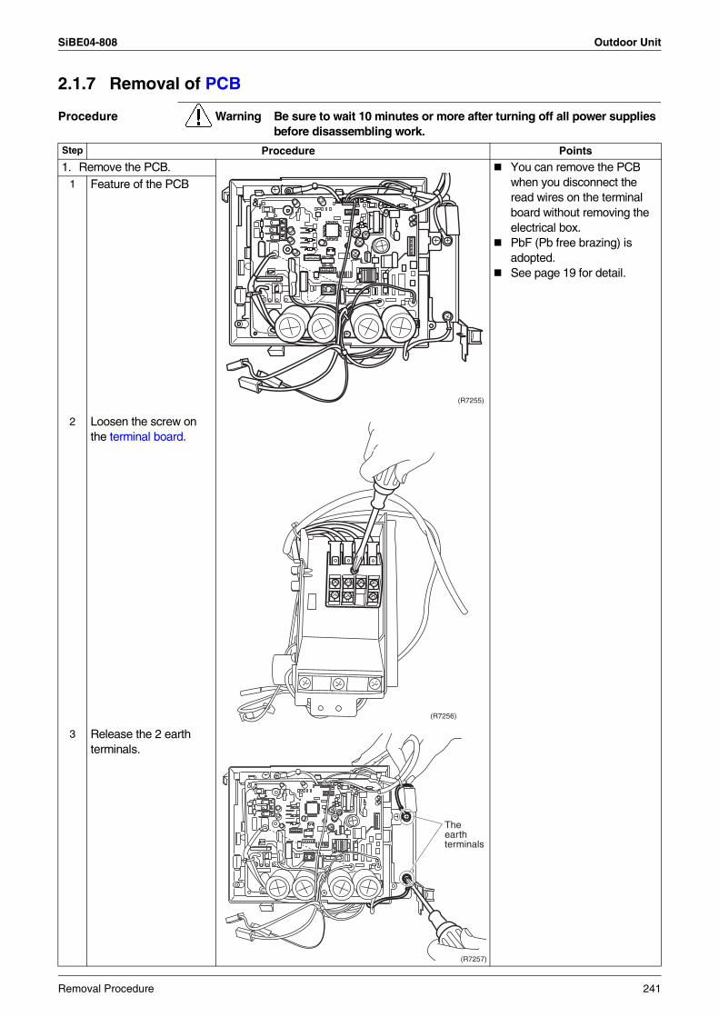
SiBE04-808 Outdoor Unit
2.1.7 Removal of PCB
Procedure Warning Be sure to wait 10 minutes or more after turning off all power supplies before disassembling work.
Step Procedure Points
1. Remove the PCB. You can remove the PCB when you disconnect the read wires on the terminal board without removing the electrical box.PbF (Pb free brazing) is adopted.See page 19 for detail.
1 Feature of the PCB
2 Loosen the screw on the terminal board.
3 Release the 2 earth terminals.
(R7255)
(R7256)
(R7257)
Theearthterminals
Removal Procedure 241
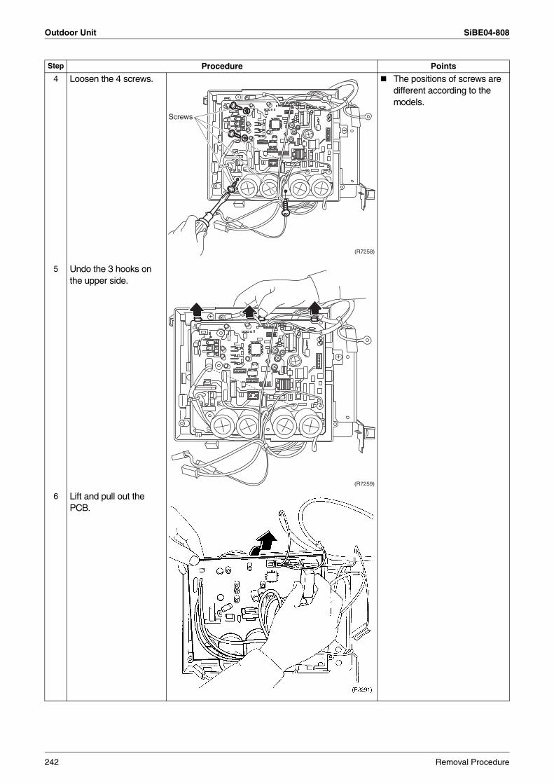
Outdoor Unit SiBE04-808
4 Loosen the 4 screws. The positions of screws are different according to the models.
5 Undo the 3 hooks on the upper side.
6 Lift and pull out the PCB.
Step Procedure Points
(R7258)
Screws
(R7259)
242 Removal Procedure
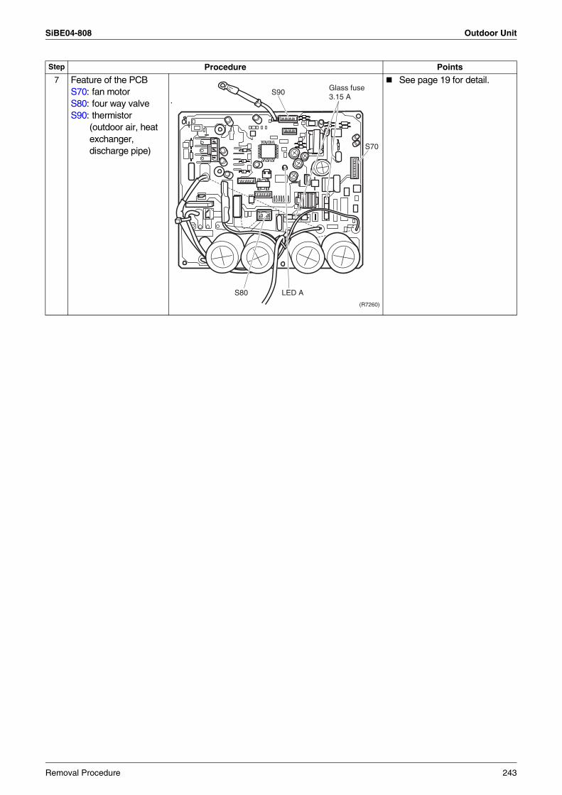
SiBE04-808 Outdoor Unit
7 Feature of the PCBS70: fan motorS80: four way valveS90: thermistor
(outdoor air, heat exchanger, discharge pipe)
See page 19 for detail.
Step Procedure Points
(R7260)
S80 LED A
S90 Glass fuse 3.15 A
S70
Removal Procedure 243
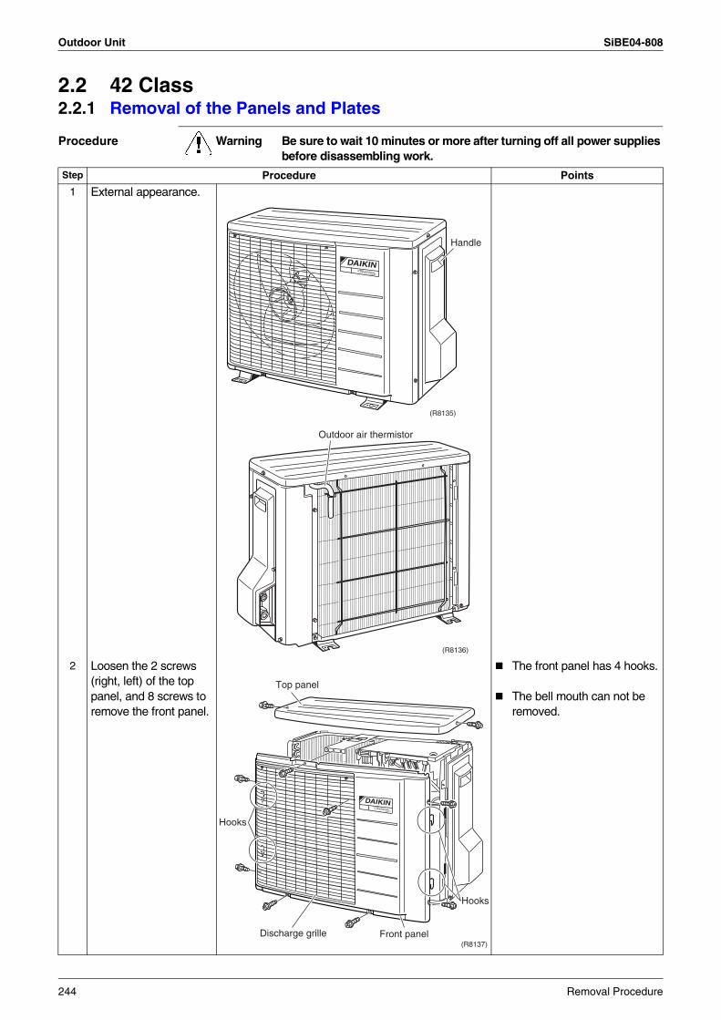
Outdoor Unit SiBE04-808
2.2 42 Class2.2.1 Removal of the Panels and Plates
Procedure Warning Be sure to wait 10 minutes or more after turning off all power supplies before disassembling work.
Step Procedure Points
1 External appearance.
2 Loosen the 2 screws (right, left) of the top panel, and 8 screws to remove the front panel.
The front panel has 4 hooks.
The bell mouth can not be removed.
DAIKININVERTER
Handle
(R8135)
Outdoor air thermistor
(R8136)
DAIKININVERTER
(R8137)
Top panel
Hooks
Discharge grille Front panel
Hooks
244 Removal Procedure
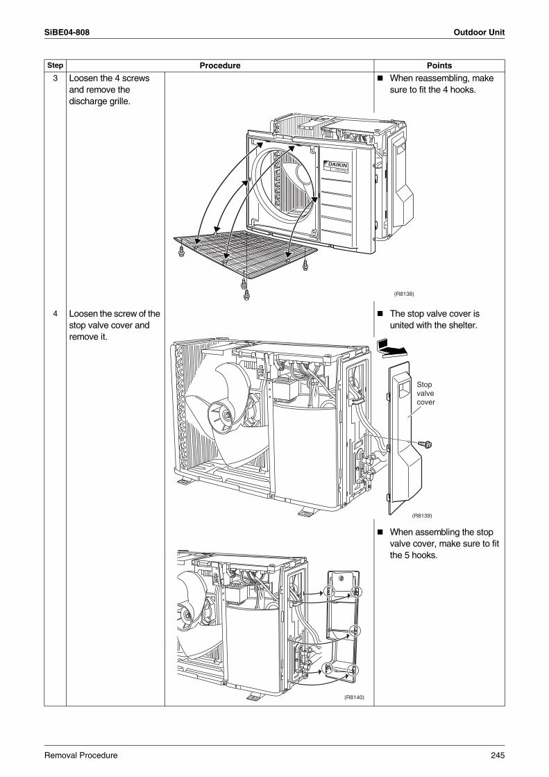
SiBE04-808 Outdoor Unit
3 Loosen the 4 screws and remove the discharge grille.
When reassembling, make sure to fit the 4 hooks.
4 Loosen the screw of the stop valve cover and remove it.
The stop valve cover is united with the shelter.
When assembling the stop valve cover, make sure to fit the 5 hooks.
Step Procedure Points
DAIKININVERTER
(R8138)
Stop valve cover
(R8139)
(R8140)
Removal Procedure 245
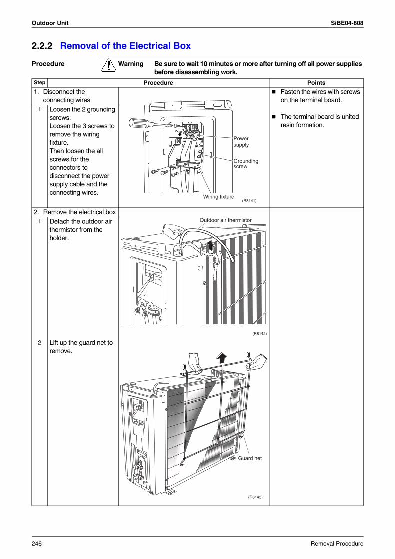
Outdoor Unit SiBE04-808
2.2.2 Removal of the Electrical Box
Procedure Warning Be sure to wait 10 minutes or more after turning off all power supplies before disassembling work.
Step Procedure Points
1. Disconnect the connecting wires
Fasten the wires with screws on the terminal board.
The terminal board is united resin formation.
1 Loosen the 2 grounding screws.Loosen the 3 screws to remove the wiring fixture.Then loosen the all screws for the connectors to disconnect the power supply cable and the connecting wires.
2. Remove the electrical box1 Detach the outdoor air
thermistor from the holder.
2 Lift up the guard net to remove.
Wiring fixture
Powersupply
Groundingscrew
(R8141)
(R8142)
Outdoor air thermistor
(R8143)
Guard net
246 Removal Procedure
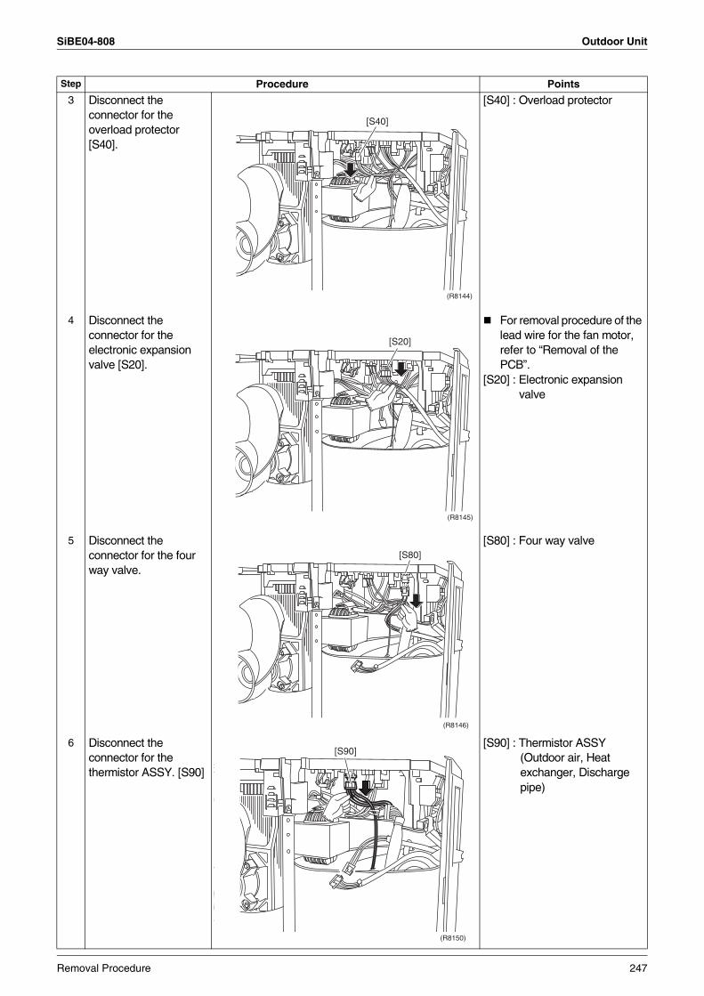
SiBE04-808 Outdoor Unit
3 Disconnect the connector for the overload protector [S40].
[S40] : Overload protector
4 Disconnect the connector for the electronic expansion valve [S20].
For removal procedure of the lead wire for the fan motor, refer to “Removal of the PCB”.
[S20] : Electronic expansion valve
5 Disconnect the connector for the four way valve.
[S80] : Four way valve
6 Disconnect the connector for the thermistor ASSY. [S90]
[S90] : Thermistor ASSY(Outdoor air, Heat exchanger, Discharge pipe)
Step Procedure Points
[S40]
(R8144)
[S20]
(R8145)
[S80]
(R8146)
[S90]
(R8150)
Removal Procedure 247
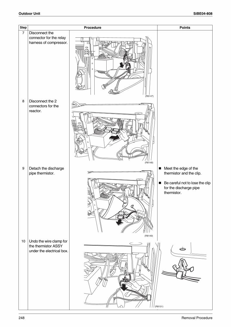
Outdoor Unit SiBE04-808
7 Disconnect the connector for the relay harness of compressor.
8 Disconnect the 2 connectors for the reactor.
9 Detach the discharge pipe thermistor.
Meet the edge of the thermistor and the clip.
Be careful not to lose the clip for the discharge pipe thermistor.
10 Undo the wire clamp for the thermistor ASSY under the electrical box.
Step Procedure Points
(R8147)
(R8148)
(R8149)
(R8151)
248 Removal Procedure
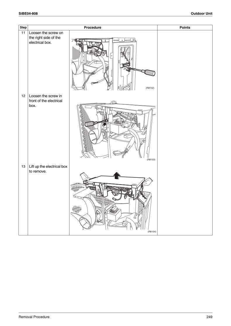
SiBE04-808 Outdoor Unit
11 Loosen the screw on the right side of the electrical box.
12 Loosen the screw in front of the electrical box.
13 Lift up the electrical box to remove.
Step Procedure Points
(R8152)
(R8153)
(R8154)
Removal Procedure 249
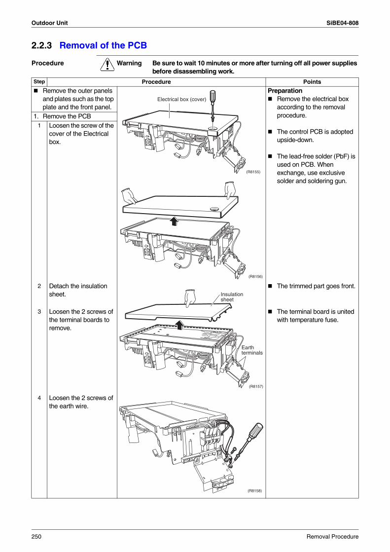
Outdoor Unit SiBE04-808
2.2.3 Removal of the PCB
Procedure Warning Be sure to wait 10 minutes or more after turning off all power supplies before disassembling work.
Step Procedure Points
Remove the outer panels and plates such as the top plate and the front panel.
PreparationRemove the electrical box according to the removal procedure.
The control PCB is adopted upside-down.
The lead-free solder (PbF) is used on PCB. When exchange, use exclusive solder and soldering gun.
1. Remove the PCB1 Loosen the screw of the
cover of the Electrical box.
2 Detach the insulation sheet.
The trimmed part goes front.
3 Loosen the 2 screws of the terminal boards to remove.
The terminal board is united with temperature fuse.
4 Loosen the 2 screws of the earth wire.
Electrical box (cover)
(R8155)
(R8156)
Insulation sheet
Earth terminals
(R8157)
(R8158)
250 Removal Procedure
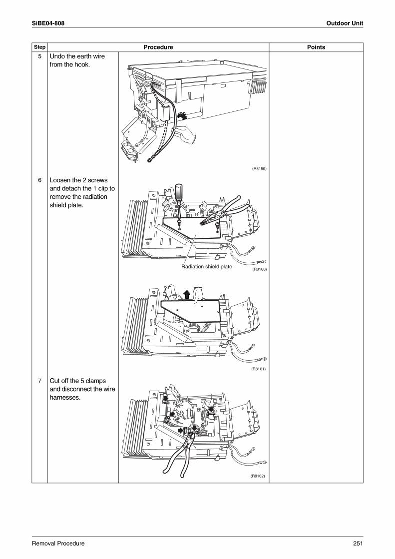
SiBE04-808 Outdoor Unit
5 Undo the earth wire from the hook.
6 Loosen the 2 screws and detach the 1 clip to remove the radiation shield plate.
7 Cut off the 5 clamps and disconnect the wire harnesses.
Step Procedure Points
(R8159)
Radiation shield plate (R8160)
(R8161)
(R8162)
Removal Procedure 251
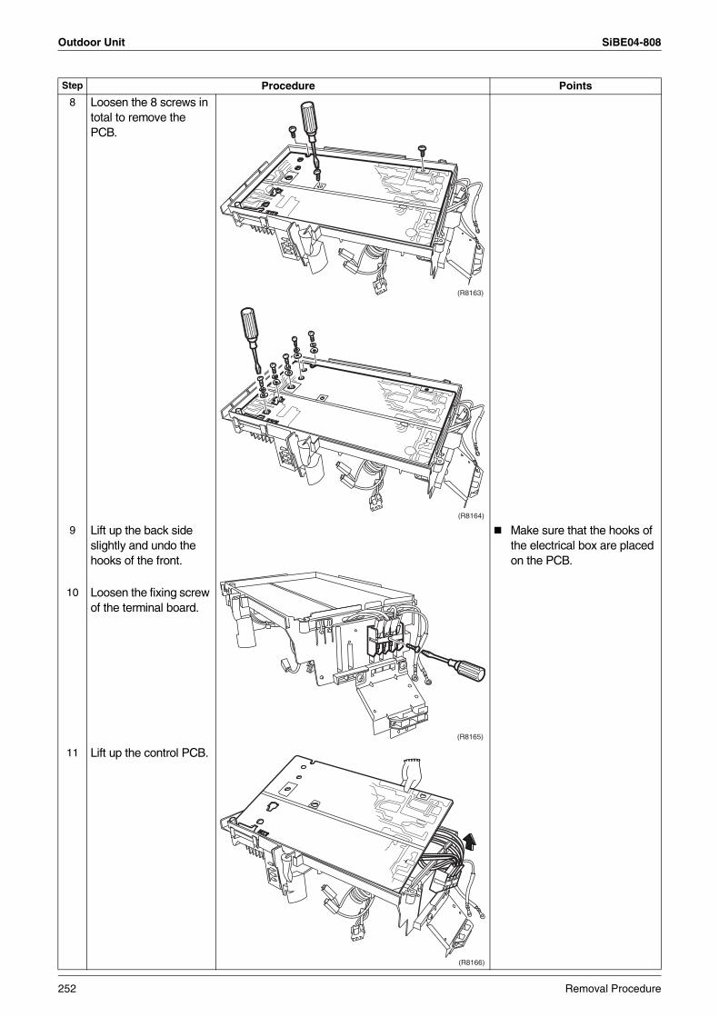
Outdoor Unit SiBE04-808
8 Loosen the 8 screws in total to remove the PCB.
9 Lift up the back side slightly and undo the hooks of the front.
Make sure that the hooks of the electrical box are placed on the PCB.
10 Loosen the fixing screw of the terminal board.
11 Lift up the control PCB.
Step Procedure Points
(R8163)
(R8164)
(R8165)
(R8166)
252 Removal Procedure
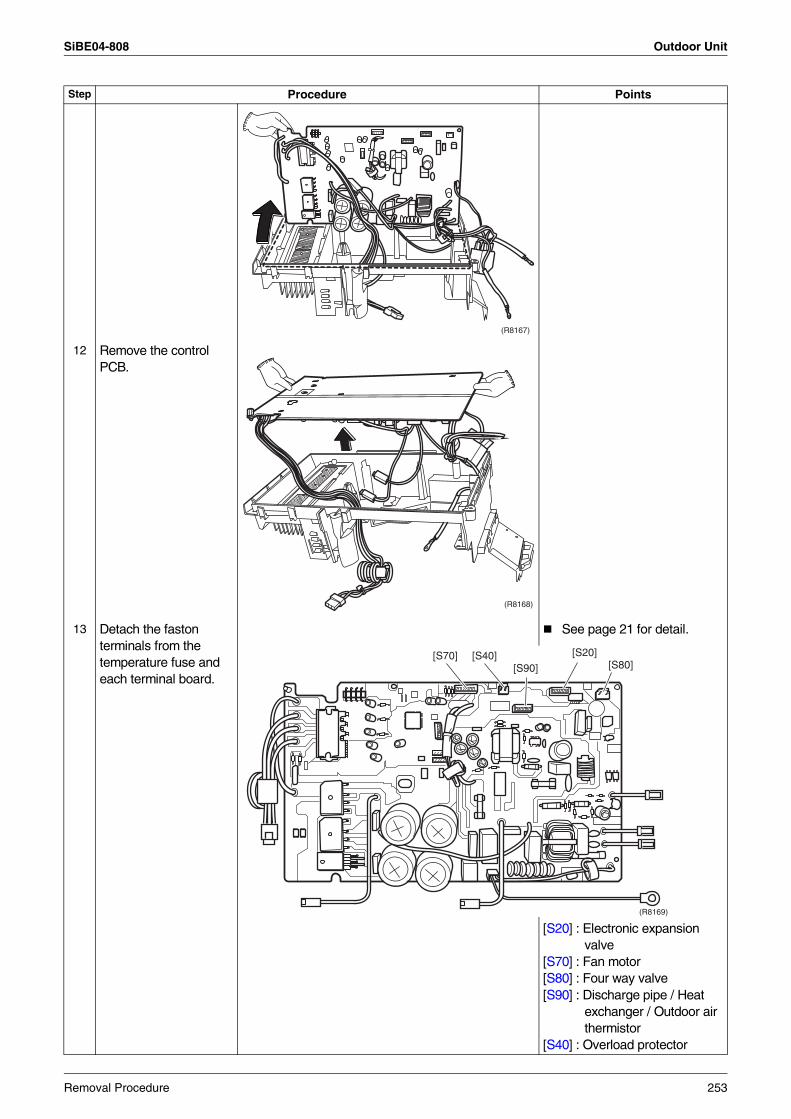
SiBE04-808 Outdoor Unit
12 Remove the control PCB.
13 Detach the faston terminals from the temperature fuse and each terminal board.
See page 21 for detail.
[S20] : Electronic expansion valve
[S70] : Fan motor[S80] : Four way valve[S90] : Discharge pipe / Heat
exchanger / Outdoor air thermistor
[S40] : Overload protector
Step Procedure Points
(R8167)
(R8168)
[S70] [S40] [S20]
[S90] [S80]
(R8169)
Removal Procedure 253
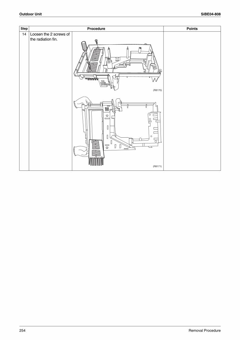
Outdoor Unit SiBE04-808
14 Loosen the 2 screws of the radiation fin.
Step Procedure Points
(R8170)
(R8171)
254 Removal Procedure
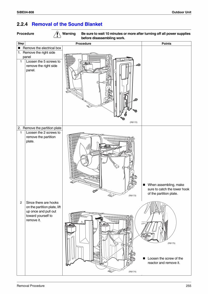
SiBE04-808 Outdoor Unit
2.2.4 Removal of the Sound Blanket
Procedure Warning Be sure to wait 10 minutes or more after turning off all power supplies before disassembling work.
Step Procedure PointsRemove the electrical box
1. Remove the right side panel
1 Loosen the 5 screws to remove the right side panel.
2. Remove the partition plate
When assembling, make sure to catch the lower hook of the partition plate.
1 Loosen the 2 screws to remove the partition plate.
2 Since there are hooks on the partition plate, lift up once and pull out toward yourself to remove it.
(R8172)
(R8173)
(R8174)
(R8175)
Loosen the screw of the reactor and remove it.
Removal Procedure 255
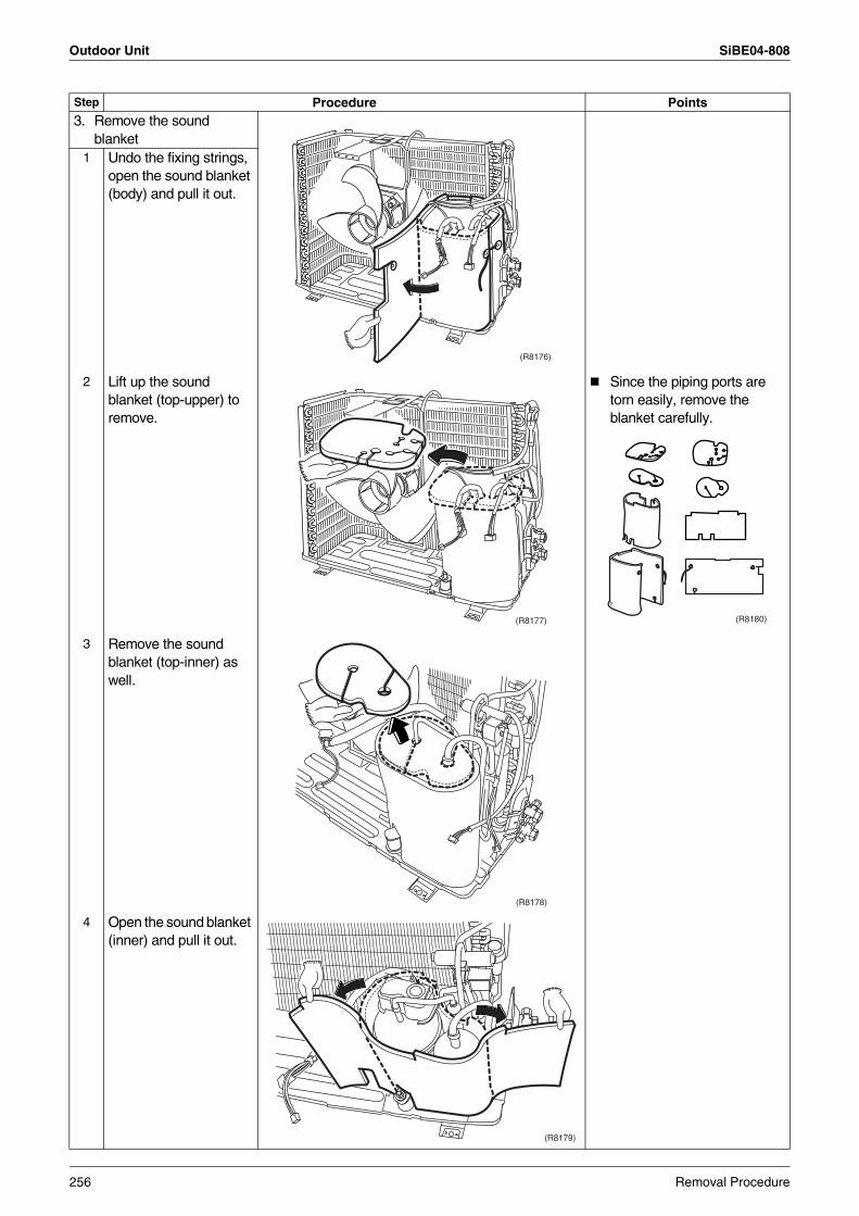
Outdoor Unit SiBE04-808
3. Remove the sound blanket
1 Undo the fixing strings, open the sound blanket (body) and pull it out.
2 Lift up the sound blanket (top-upper) to remove.
Since the piping ports are torn easily, remove the blanket carefully.
3 Remove the sound blanket (top-inner) as well.
4 Open the sound blanket (inner) and pull it out.
Step Procedure Points
(R8176)
(R8177) (R8180)
(R8178)
(R8179)
256 Removal Procedure
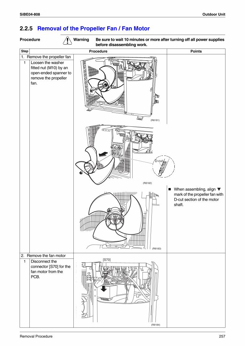
SiBE04-808 Outdoor Unit
2.2.5 Removal of the Propeller Fan / Fan Motor
Procedure Warning Be sure to wait 10 minutes or more after turning off all power supplies before disassembling work.
Step Procedure Points
1. Remove the propeller fan1 Loosen the washer
fitted nut (M10) by an open-ended spanner to remove the propeller fan.
When assembling, align mark of the propeller fan with D-cut section of the motor shaft.
2. Remove the fan motor1 Disconnect the
connector [S70] for the fan motor from the PCB.
(R8181)
(R8182)
D-cut
(R8183)
[S70]
(R8184)
Removal Procedure 257
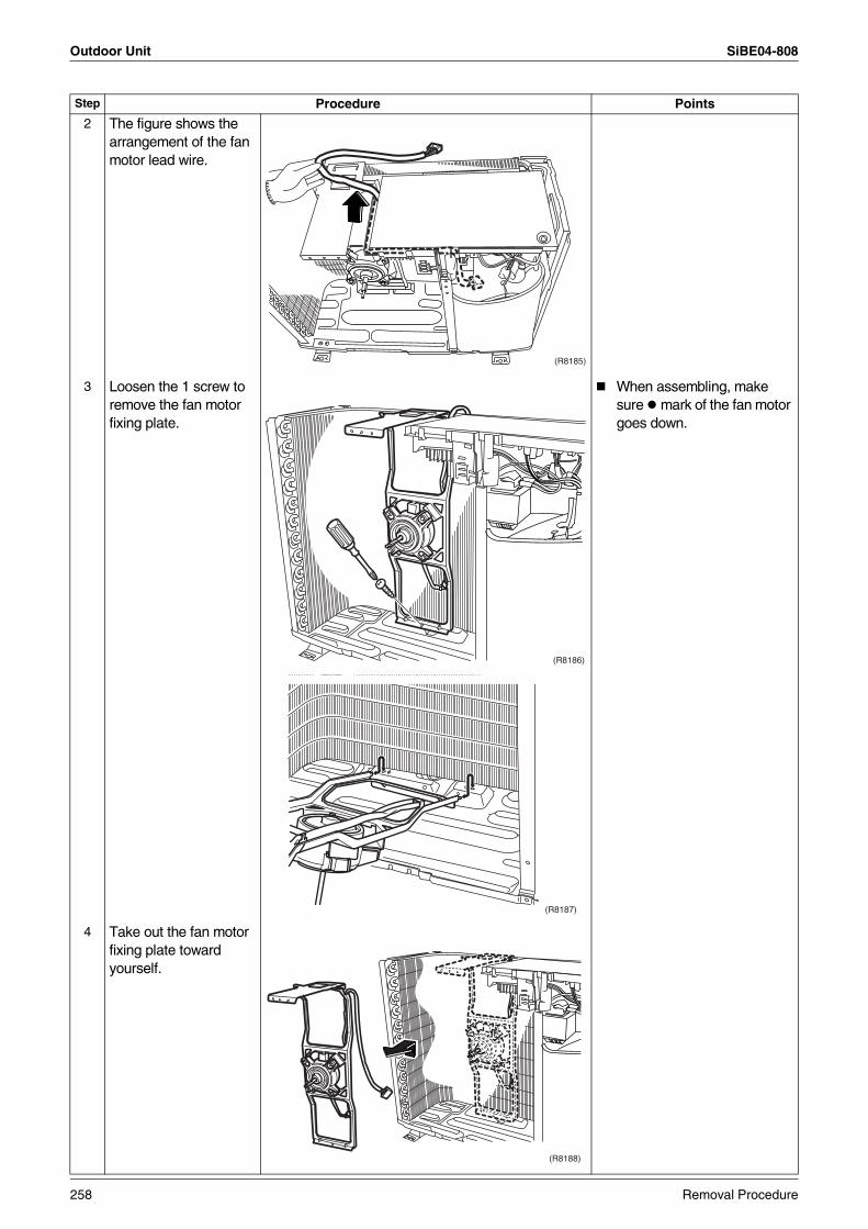
Outdoor Unit SiBE04-808
2 The figure shows the arrangement of the fan motor lead wire.
3 Loosen the 1 screw to remove the fan motor fixing plate.
When assembling, make sure mark of the fan motor goes down.
4 Take out the fan motor fixing plate toward yourself.
Step Procedure Points
(R8185)
(R8186)
(R8187)
(R8188)
258 Removal Procedure
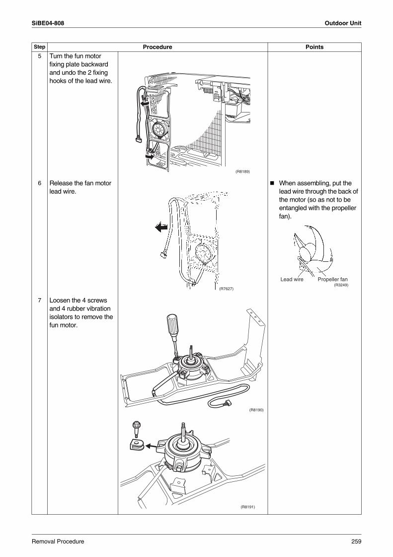
SiBE04-808 Outdoor Unit
5 Turn the fun motor fixing plate backward and undo the 2 fixing hooks of the lead wire.
6 Release the fan motor lead wire.
When assembling, put the lead wire through the back of the motor (so as not to be entangled with the propeller fan).
7 Loosen the 4 screws and 4 rubber vibration isolators to remove the fun motor.
Step Procedure Points
(R8189)
(R7627)
Lead wire Propeller fan(R3249)
(R8190)
(R8191)
Removal Procedure 259
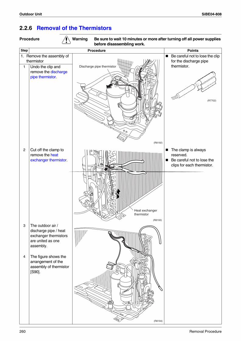
Outdoor Unit SiBE04-808
2.2.6 Removal of the Thermistors
Procedure Warning Be sure to wait 10 minutes or more after turning off all power supplies before disassembling work.
Step Procedure Points
1. Remove the assembly of thermistor
Be careful not to lose the clip for the discharge pipe thermistor.1 Undo the clip and
remove the discharge pipe thermistor.
2 Cut off the clamp to remove the heat exchanger thermistor.
The clamp is always reserved.Be careful not to lose the clips for each thermistor.
3 The outdoor air / discharge pipe / heat exchanger thermistors are united as one assembly.
4 The figure shows the arrangement of the assembly of thermistor [S90].
(R8192)
Discharge pipe thermistor
(R7702)
(R8193)
Heat exchanger thermistor
(R8194)
260 Removal Procedure
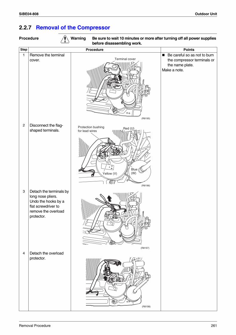
SiBE04-808 Outdoor Unit
2.2.7 Removal of the Compressor
Procedure Warning Be sure to wait 10 minutes or more after turning off all power supplies before disassembling work.
Step Procedure Points
1 Remove the terminal cover.
Be careful so as not to burn the compressor terminals or the name plate.
Make a note.
2 Disconnect the flag-shaped terminals.
3 Detach the terminals by long nose pliers.Undo the hooks by a flat screwdriver to remove the overload protector.
4 Detach the overload protector.
Terminal cover
(R8195)
WV U
Protection bushing for lead wires
Red (U)
Yellow (V)Blue(W)
(R8196)
UW
V
(R8197)
UW
V
(R8198)
Removal Procedure 261
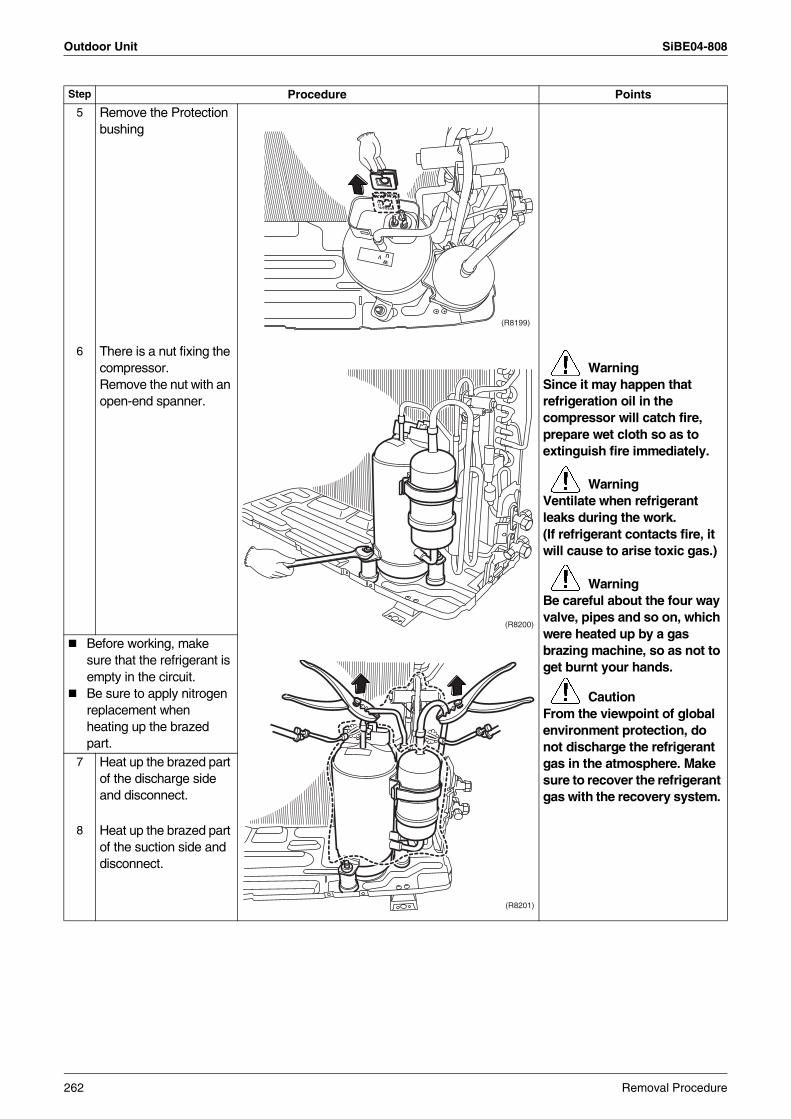
Outdoor Unit SiBE04-808
5 Remove the Protection bushing
6 There is a nut fixing the compressor.Remove the nut with an open-end spanner.
WarningSince it may happen that refrigeration oil in the compressor will catch fire, prepare wet cloth so as to extinguish fire immediately.
WarningVentilate when refrigerant leaks during the work.(If refrigerant contacts fire, it will cause to arise toxic gas.)
WarningBe careful about the four way valve, pipes and so on, which were heated up by a gas brazing machine, so as not to get burnt your hands.
CautionFrom the viewpoint of global environment protection, do not discharge the refrigerant gas in the atmosphere. Make sure to recover the refrigerant gas with the recovery system.
Before working, make sure that the refrigerant is empty in the circuit.Be sure to apply nitrogen replacement when heating up the brazed part.
7 Heat up the brazed part of the discharge side and disconnect.
8 Heat up the brazed part of the suction side and disconnect.
Step Procedure Points
UW
V
(R8199)
(R8200)
(R8201)
262 Removal Procedure
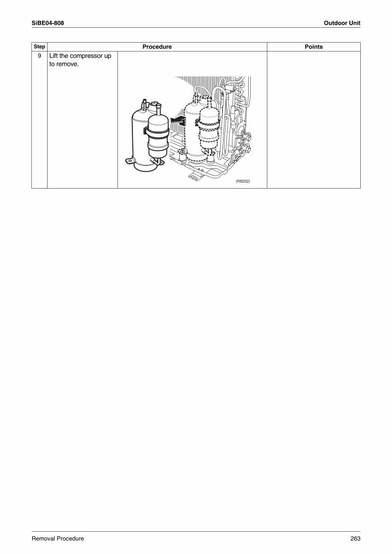
SiBE04-808 Outdoor Unit
9 Lift the compressor up to remove.
Step Procedure Points
(R8202)
Removal Procedure 263
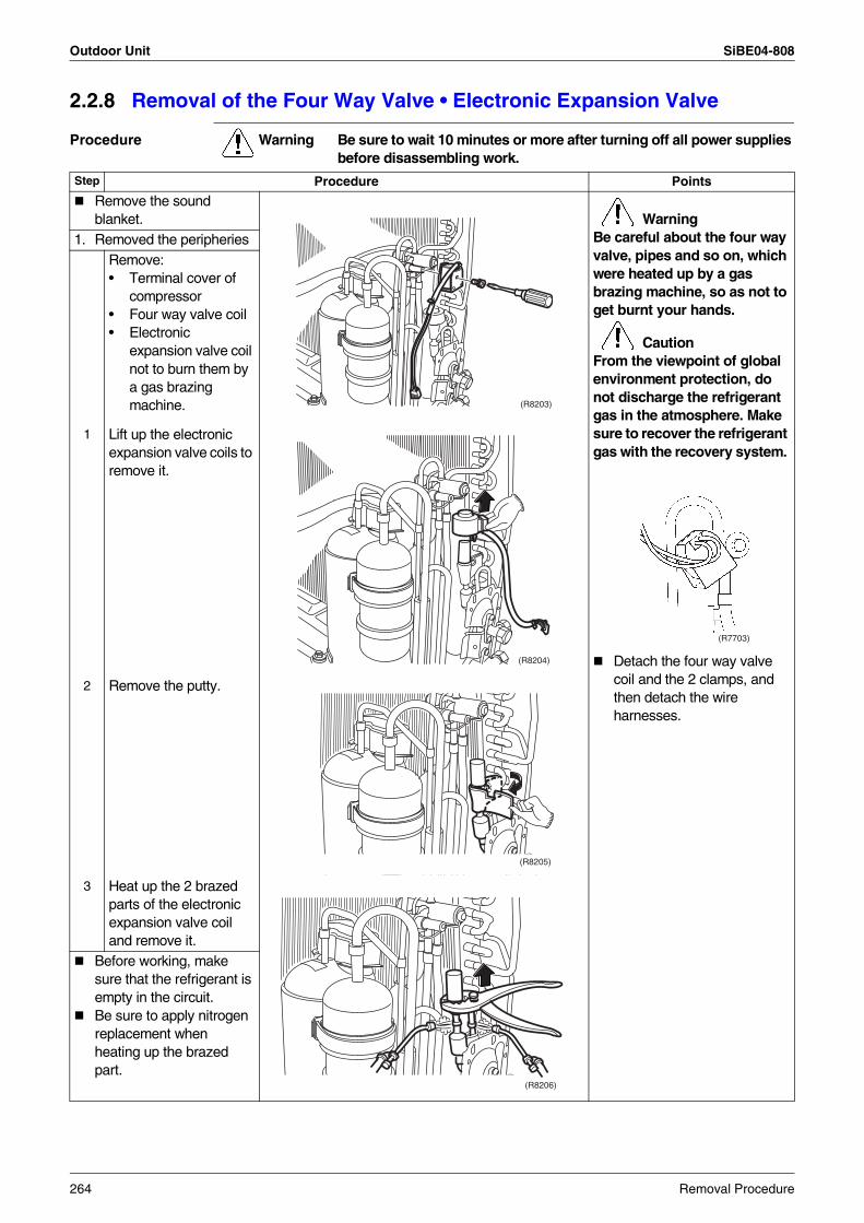
Outdoor Unit SiBE04-808
2.2.8 Removal of the Four Way Valve • Electronic Expansion Valve
Procedure Warning Be sure to wait 10 minutes or more after turning off all power supplies before disassembling work.
Step Procedure Points
Remove the sound blanket. Warning
Be careful about the four way valve, pipes and so on, which were heated up by a gas brazing machine, so as not to get burnt your hands.
CautionFrom the viewpoint of global environment protection, do not discharge the refrigerant gas in the atmosphere. Make sure to recover the refrigerant gas with the recovery system.
Detach the four way valve coil and the 2 clamps, and then detach the wire harnesses.
1. Removed the peripheriesRemove:• Terminal cover of
compressor• Four way valve coil• Electronic
expansion valve coil not to burn them by a gas brazing machine.
1 Lift up the electronic expansion valve coils to remove it.
2 Remove the putty.
3 Heat up the 2 brazed parts of the electronic expansion valve coil and remove it.
Before working, make sure that the refrigerant is empty in the circuit.Be sure to apply nitrogen replacement when heating up the brazed part.
(R8203)
(R7703)
(R8204)
(R8205)
(R8206)
264 Removal Procedure
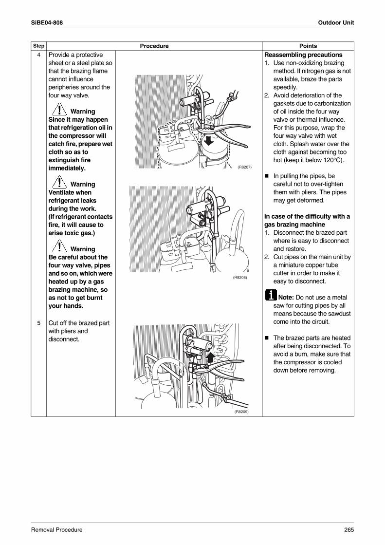
SiBE04-808 Outdoor Unit
4 Provide a protective sheet or a steel plate so that the brazing flame cannot influence peripheries around the four way valve.
WarningSince it may happen that refrigeration oil in the compressor will catch fire, prepare wet cloth so as to extinguish fire immediately.
WarningVentilate when refrigerant leaks during the work.(If refrigerant contacts fire, it will cause to arise toxic gas.)
WarningBe careful about the four way valve, pipes and so on, which were heated up by a gas brazing machine, so as not to get burnt your hands.
Reassembling precautions1. Use non-oxidizing brazing
method. If nitrogen gas is not available, braze the parts speedily.
2. Avoid deterioration of the gaskets due to carbonization of oil inside the four way valve or thermal influence. For this purpose, wrap the four way valve with wet cloth. Splash water over the cloth against becoming too hot (keep it below 120°C).
In pulling the pipes, be careful not to over-tighten them with pliers. The pipes may get deformed.
In case of the difficulty with a gas brazing machine 1. Disconnect the brazed part
where is easy to disconnect and restore.
2. Cut pipes on the main unit by a miniature copper tube cutter in order to make it easy to disconnect.
Note: Do not use a metal saw for cutting pipes by all means because the sawdust come into the circuit.
The brazed parts are heated after being disconnected. To avoid a burn, make sure that the compressor is cooled down before removing.
5 Cut off the brazed part with pliers and disconnect.
Step Procedure Points
(R8207)
(R8208)
(R8209)
Removal Procedure 265
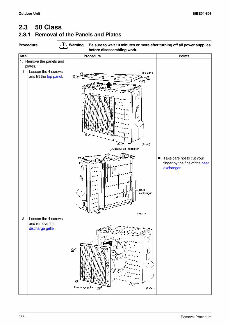
Outdoor Unit SiBE04-808
2.3 50 Class2.3.1 Removal of the Panels and Plates
Procedure Warning Be sure to wait 10 minutes or more after turning off all power supplies before disassembling work.
Step Procedure Points
1. Remove the panels and plates.
Take care not to cut your finger by the fins of the heat exchanger.
1 Loosen the 4 screws and lift the top panel.
2 Loosen the 4 screws and remove the discharge grille.
266 Removal Procedure
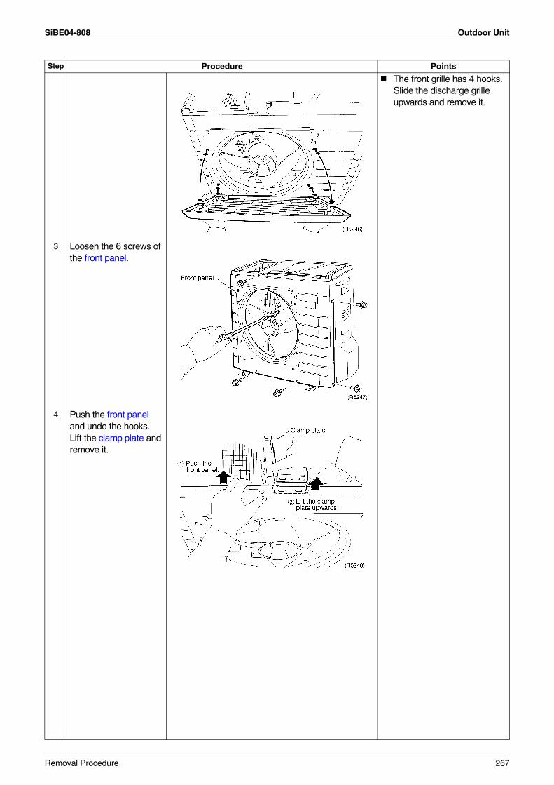
SiBE04-808 Outdoor Unit
The front grille has 4 hooks. Slide the discharge grille upwards and remove it.
3 Loosen the 6 screws of the front panel.
4 Push the front panel and undo the hooks. Lift the clamp plate and remove it.
Step Procedure Points
Removal Procedure 267
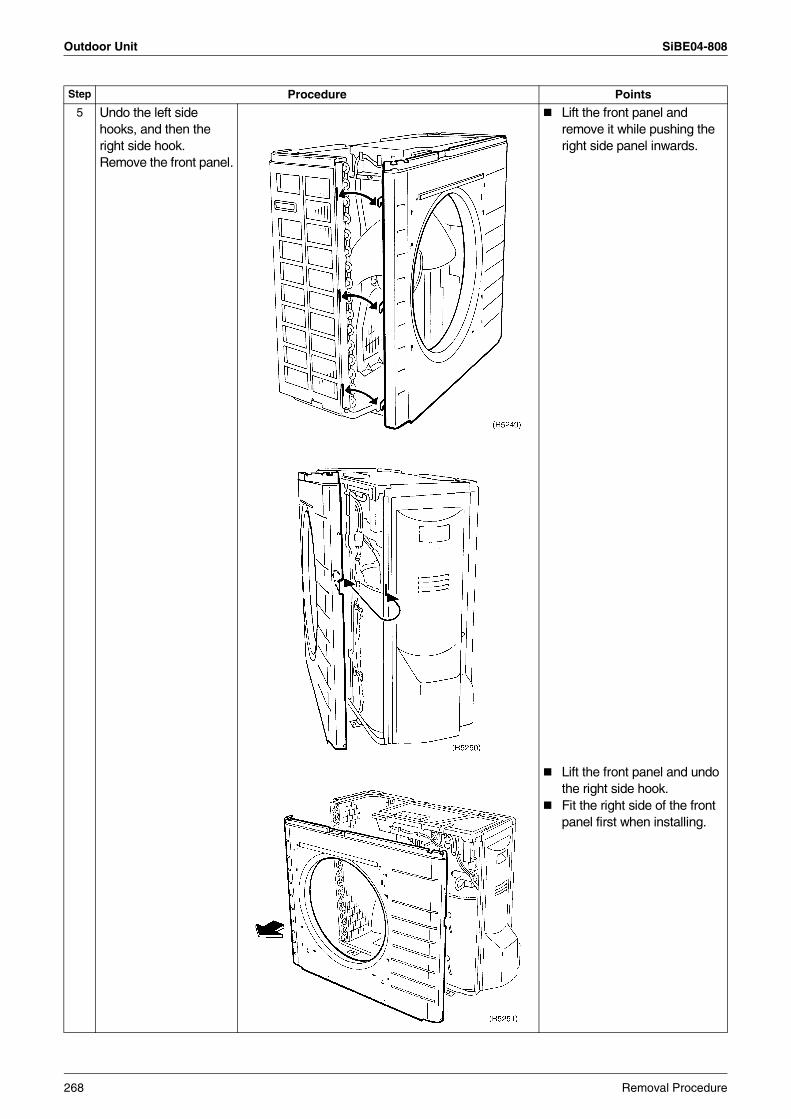
Outdoor Unit SiBE04-808
5 Undo the left side hooks, and then the right side hook.Remove the front panel.
Lift the front panel and remove it while pushing the right side panel inwards.
Lift the front panel and undo the right side hook.Fit the right side of the front panel first when installing.
Step Procedure Points
268 Removal Procedure
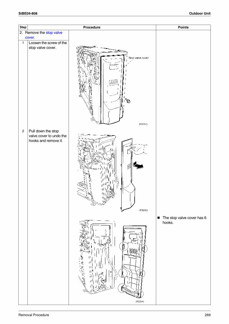
SiBE04-808 Outdoor Unit
2. Remove the stop valve cover.
1 Loosen the screw of the stop valve cover.
2 Pull down the stop valve cover to undo the hooks and remove it.
The stop valve cover has 6 hooks.
Step Procedure Points
(R5254)
Removal Procedure 269
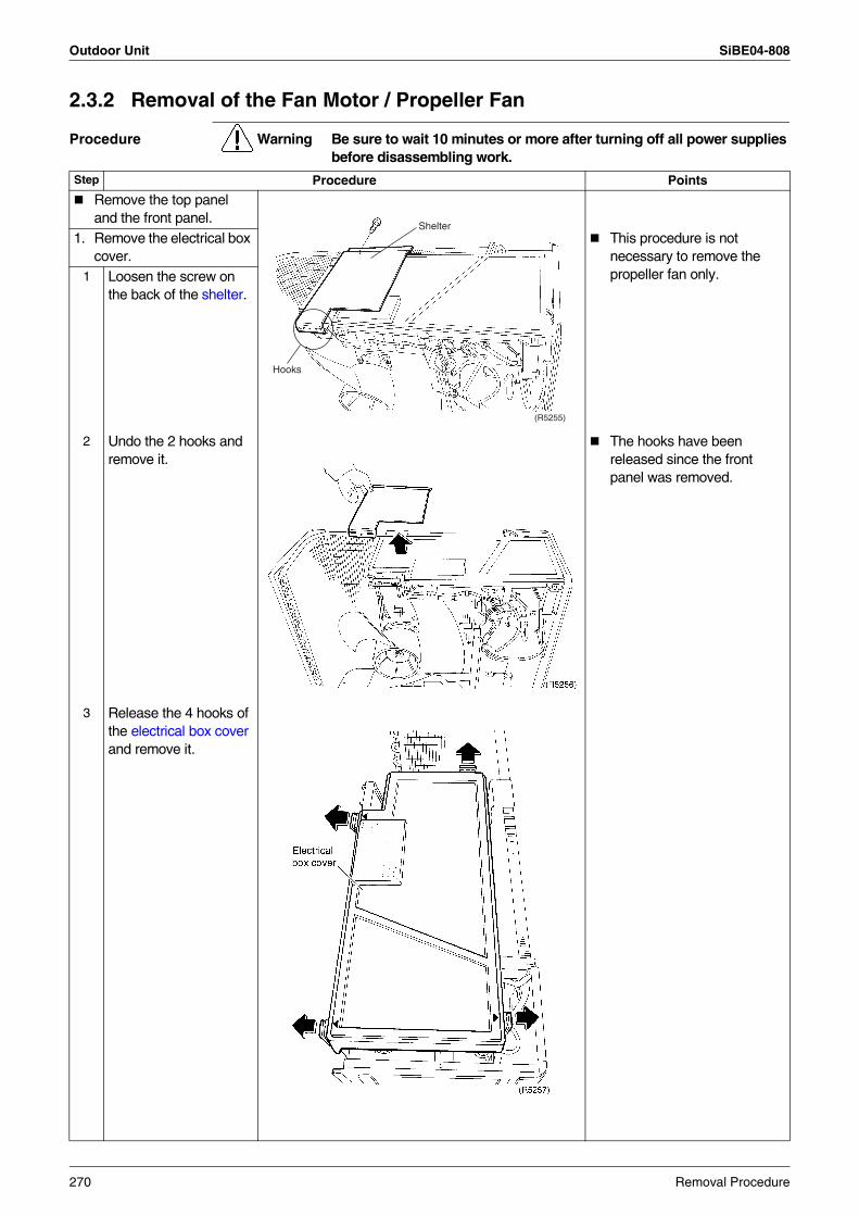
Outdoor Unit SiBE04-808
2.3.2 Removal of the Fan Motor / Propeller Fan
Procedure Warning Be sure to wait 10 minutes or more after turning off all power supplies before disassembling work.
Step Procedure Points
Remove the top panel and the front panel.
1. Remove the electrical box cover.
This procedure is not necessary to remove the propeller fan only.1 Loosen the screw on
the back of the shelter.
2 Undo the 2 hooks and remove it.
The hooks have been released since the front panel was removed.
3 Release the 4 hooks of the electrical box cover and remove it.
(R5255)
Shelter
Hooks
270 Removal Procedure
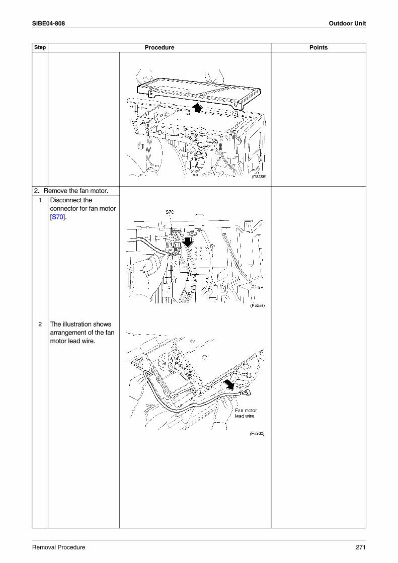
SiBE04-808 Outdoor Unit
2. Remove the fan motor.1 Disconnect the
connector for fan motor [S70].
2 The illustration shows arrangement of the fan motor lead wire.
Step Procedure Points
Removal Procedure 271
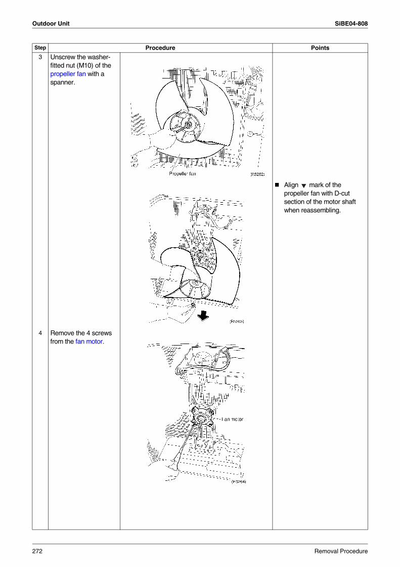
Outdoor Unit SiBE04-808
3 Unscrew the washer-fitted nut (M10) of the propeller fan with a spanner.
Align mark of the propeller fan with D-cut section of the motor shaft when reassembling.
4 Remove the 4 screws from the fan motor.
Step Procedure Points
272 Removal Procedure
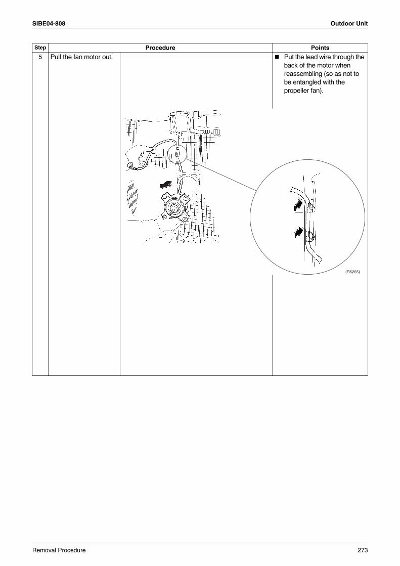
SiBE04-808 Outdoor Unit
5 Pull the fan motor out. Put the lead wire through the back of the motor when reassembling (so as not to be entangled with the propeller fan).
Step Procedure Points
(R5265)
Removal Procedure 273
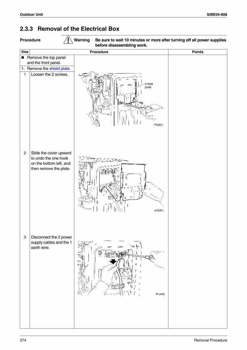
Outdoor Unit SiBE04-808
2.3.3 Removal of the Electrical Box
Procedure Warning Be sure to wait 10 minutes or more after turning off all power supplies before disassembling work.
Step Procedure Points
Remove the top panel and the front panel.
1. Remove the shield plate.1 Loosen the 2 screws.
2 Slide the cover upward to undo the one hook on the bottom left, and then remove the plate.
3 Disconnect the 2 power supply cables and the 1 earth wire.
274 Removal Procedure
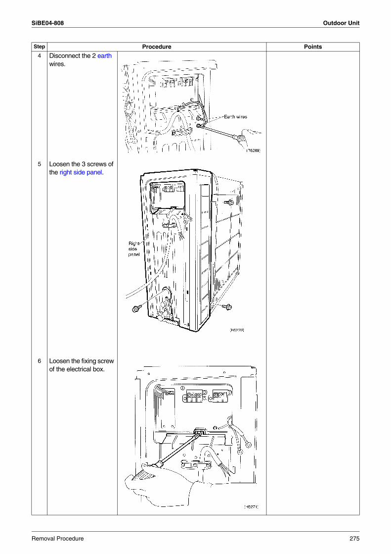
SiBE04-808 Outdoor Unit
4 Disconnect the 2 earth wires.
5 Loosen the 3 screws of the right side panel.
6 Loosen the fixing screw of the electrical box.
Step Procedure Points
Removal Procedure 275
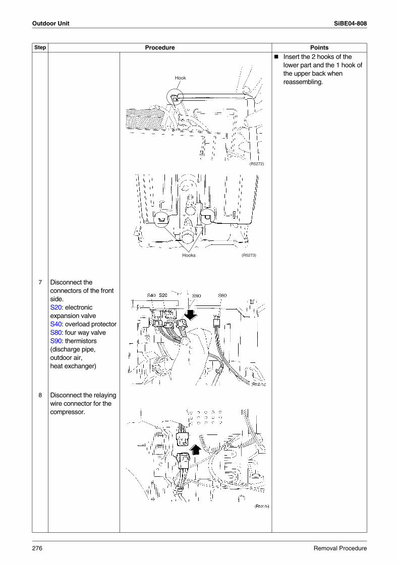
Outdoor Unit SiBE04-808
Insert the 2 hooks of the lower part and the 1 hook of the upper back when reassembling.
7 Disconnect the connectors of the front side.S20: electronic expansion valveS40: overload protectorS80: four way valveS90: thermistors (discharge pipe, outdoor air, heat exchanger)
8 Disconnect the relaying wire connector for the compressor.
Step Procedure Points
(R5272)
Hook
(R5273)Hooks
276 Removal Procedure
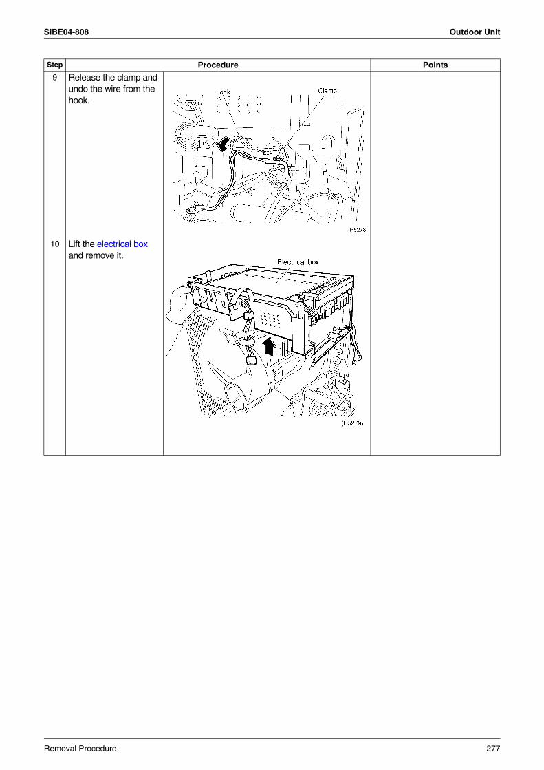
SiBE04-808 Outdoor Unit
9 Release the clamp and undo the wire from the hook.
10 Lift the electrical box and remove it.
Step Procedure Points
Removal Procedure 277
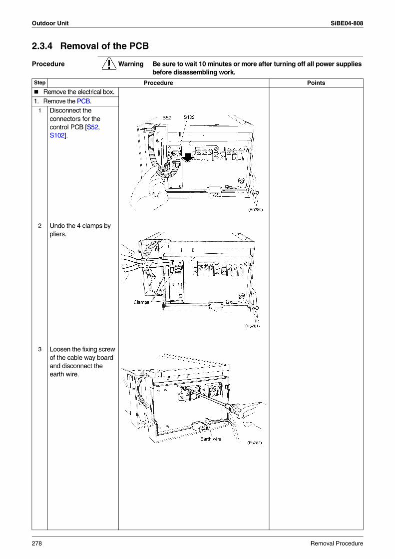
Outdoor Unit SiBE04-808
2.3.4 Removal of the PCB
Procedure Warning Be sure to wait 10 minutes or more after turning off all power supplies before disassembling work.
Step Procedure Points
Remove the electrical box.1. Remove the PCB.
1 Disconnect the connectors for the control PCB [S52, S102].
2 Undo the 4 clamps by pliers.
3 Loosen the fixing screw of the cable way boardand disconnect the earth wire.
278 Removal Procedure
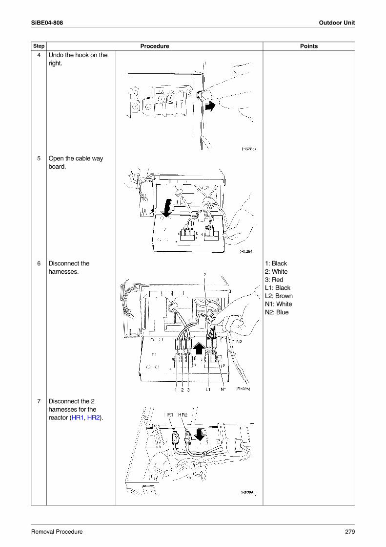
SiBE04-808 Outdoor Unit
4 Undo the hook on the right.
5 Open the cable way board.
6 Disconnect the harnesses.
1: Black2: White3: RedL1: BlackL2: BrownN1: WhiteN2: Blue
7 Disconnect the 2 harnesses for the reactor (HR1, HR2).
Step Procedure Points
Removal Procedure 279
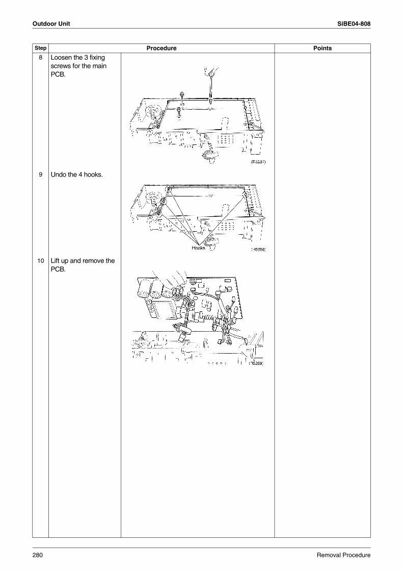
Outdoor Unit SiBE04-808
8 Loosen the 3 fixing screws for the main PCB.
9 Undo the 4 hooks.
10 Lift up and remove the PCB.
Step Procedure Points
280 Removal Procedure
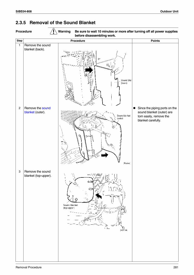
SiBE04-808 Outdoor Unit
2.3.5 Removal of the Sound Blanket
Procedure Warning Be sure to wait 10 minutes or more after turning off all power supplies before disassembling work.
Step Procedure Points
1 Remove the sound blanket (back).
2 Remove the sound blanket (outer).
Since the piping ports on the sound blanket (outer) are torn easily, remove the blanket carefully.
3 Remove the sound blanket (top-upper).
Removal Procedure 281
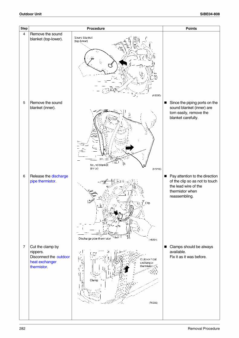
Outdoor Unit SiBE04-808
4 Remove the sound blanket (top-lower).
5 Remove the sound blanket (inner).
Since the piping ports on the sound blanket (inner) are torn easily, remove the blanket carefully.
6 Release the discharge pipe thermistor.
Pay attention to the direction of the clip so as not to touch the lead wire of the thermistor when reassembling.
7 Cut the clamp by nippers.Disconnect the outdoor heat exchanger thermistor.
Clamps should be always available. Fix it as it was before.
Step Procedure Points
282 Removal Procedure
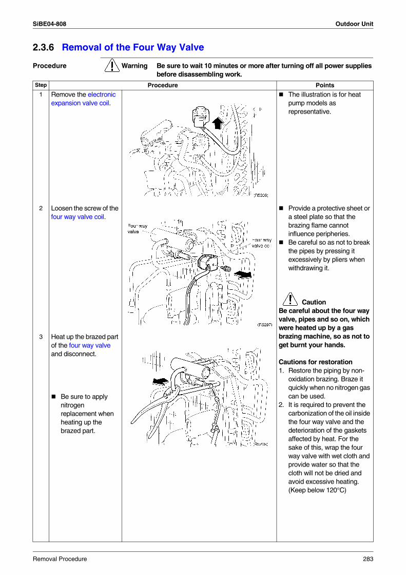
SiBE04-808 Outdoor Unit
2.3.6 Removal of the Four Way Valve
Procedure Warning Be sure to wait 10 minutes or more after turning off all power supplies before disassembling work.
Step Procedure Points
1 Remove the electronic expansion valve coil.
The illustration is for heat pump models as representative.
2 Loosen the screw of the four way valve coil.
Provide a protective sheet or a steel plate so that the brazing flame cannot influence peripheries.Be careful so as not to break the pipes by pressing it excessively by pliers when withdrawing it.
CautionBe careful about the four way valve, pipes and so on, which were heated up by a gas brazing machine, so as not to get burnt your hands.
Cautions for restoration1. Restore the piping by non-
oxidation brazing. Braze it quickly when no nitrogen gas can be used.
2. It is required to prevent the carbonization of the oil inside the four way valve and the deterioration of the gaskets affected by heat. For the sake of this, wrap the four way valve with wet cloth and provide water so that the cloth will not be dried and avoid excessive heating. (Keep below 120°C)
3 Heat up the brazed part of the four way valve and disconnect.
Be sure to apply nitrogen replacement when heating up the brazed part.
Removal Procedure 283
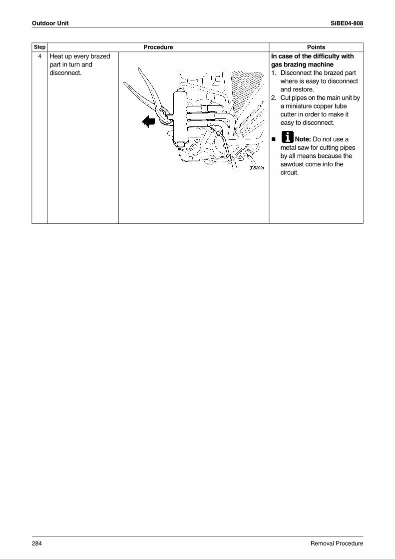
Outdoor Unit SiBE04-808
4 Heat up every brazed part in turn and disconnect.
In case of the difficulty with gas brazing machine 1. Disconnect the brazed part
where is easy to disconnect and restore.
2. Cut pipes on the main unit by a miniature copper tube cutter in order to make it easy to disconnect.
Note: Do not use a metal saw for cutting pipes by all means because the sawdust come into the circuit.
Step Procedure Points
284 Removal Procedure
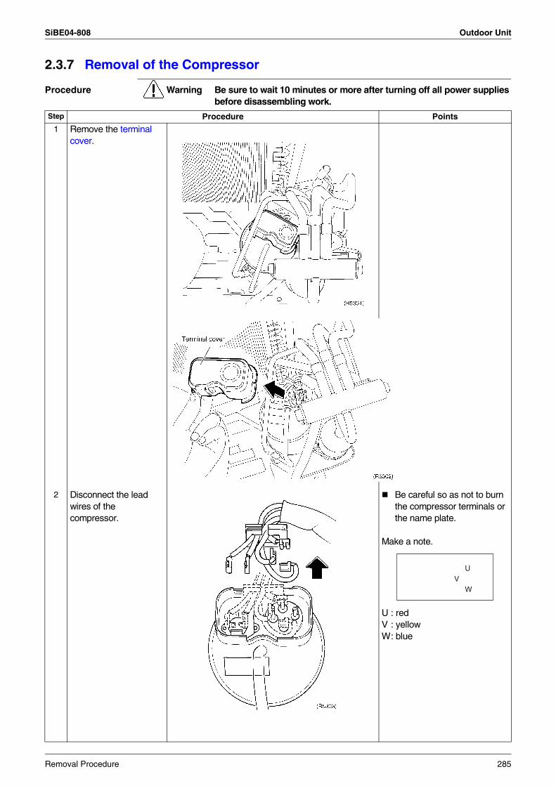
SiBE04-808 Outdoor Unit
2.3.7 Removal of the Compressor
Procedure Warning Be sure to wait 10 minutes or more after turning off all power supplies before disassembling work.
Step Procedure Points
1 Remove the terminal cover.
2 Disconnect the lead wires of the compressor.
Be careful so as not to burn the compressor terminals or the name plate.
Make a note.
U : redV : yellowW: blue
W
UV
Removal Procedure 285
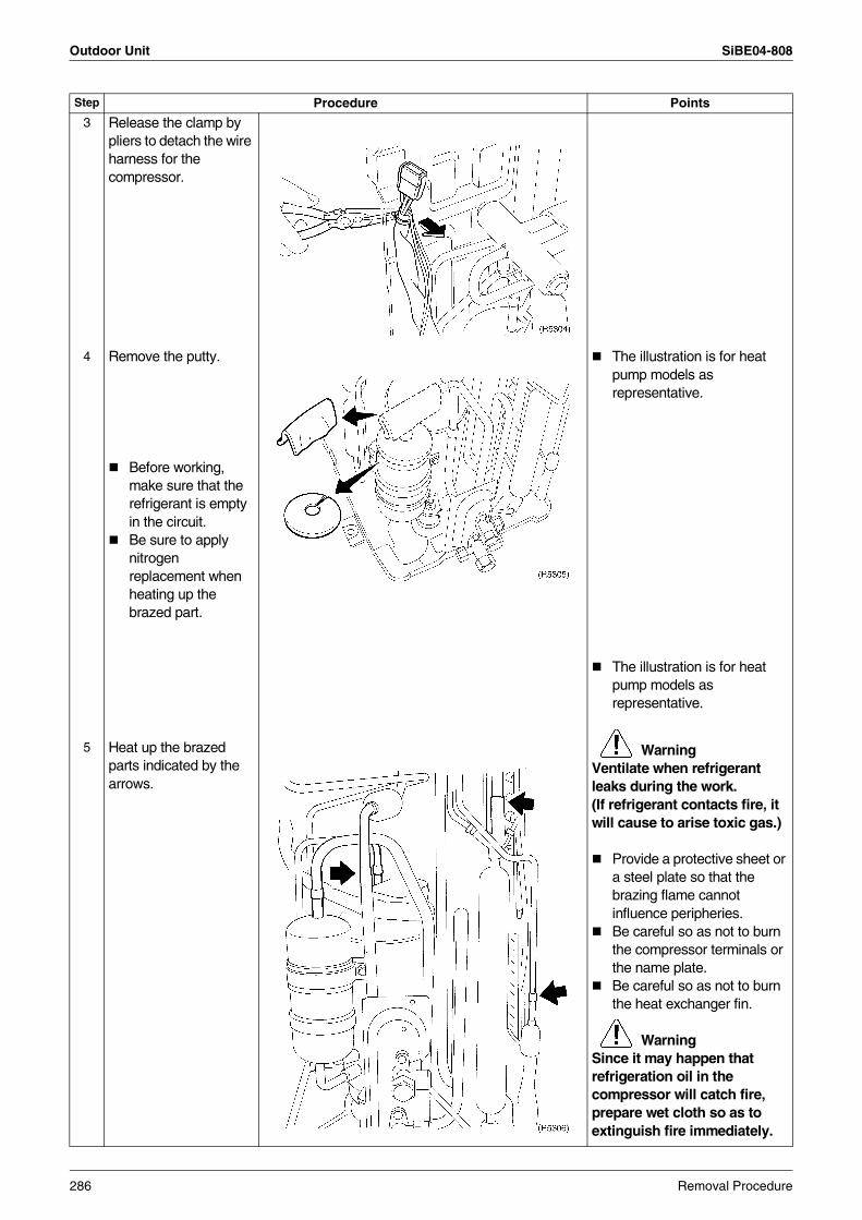
Outdoor Unit SiBE04-808
3 Release the clamp by pliers to detach the wire harness for the compressor.
4 Remove the putty. The illustration is for heat pump models as representative.
Before working, make sure that the refrigerant is empty in the circuit.Be sure to apply nitrogen replacement when heating up the brazed part.
The illustration is for heat pump models as representative.
WarningVentilate when refrigerant leaks during the work.(If refrigerant contacts fire, it will cause to arise toxic gas.)
Provide a protective sheet or a steel plate so that the brazing flame cannot influence peripheries.Be careful so as not to burn the compressor terminals or the name plate.Be careful so as not to burn the heat exchanger fin.
WarningSince it may happen that refrigeration oil in the compressor will catch fire, prepare wet cloth so as to extinguish fire immediately.
5 Heat up the brazed parts indicated by the arrows.
Step Procedure Points
286 Removal Procedure
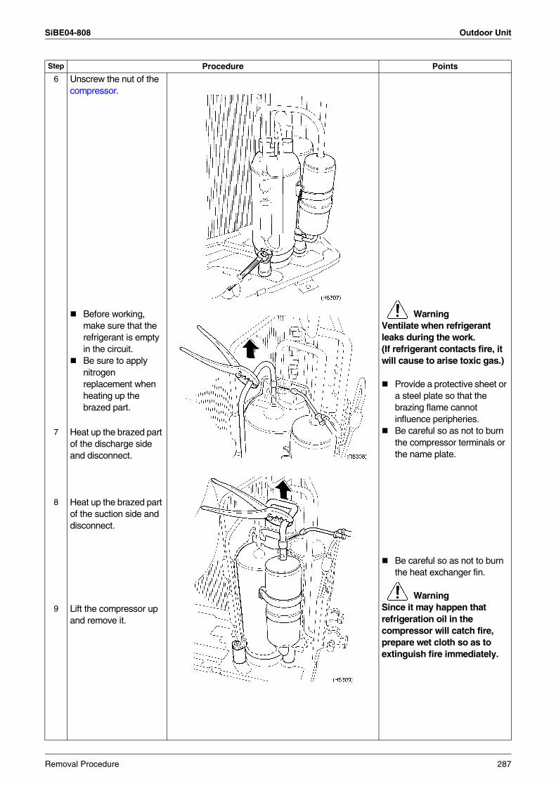
SiBE04-808 Outdoor Unit
6 Unscrew the nut of the compressor.
Before working, make sure that the refrigerant is empty in the circuit.Be sure to apply nitrogen replacement when heating up the brazed part.
WarningVentilate when refrigerant leaks during the work.(If refrigerant contacts fire, it will cause to arise toxic gas.)
Provide a protective sheet or a steel plate so that the brazing flame cannot influence peripheries.Be careful so as not to burn the compressor terminals or the name plate.
7 Heat up the brazed part of the discharge side and disconnect.
8 Heat up the brazed part of the suction side and disconnect.
Be careful so as not to burn the heat exchanger fin.
WarningSince it may happen that refrigeration oil in the compressor will catch fire, prepare wet cloth so as to extinguish fire immediately.
9 Lift the compressor up and remove it.
Step Procedure Points
Removal Procedure 287
Outdoor Unit SiBE04-808
288 Removal Procedure
SiBE04-808
Others 289
Part 8Others
1. Others .................................................................................................2901.1 Test Run from the Remote Controller ..................................................2901.2 Jumper Settings ...................................................................................2911.3 Application of Silicon Grease to a Power Transistor and
a Diode Bridge......................................................................................292
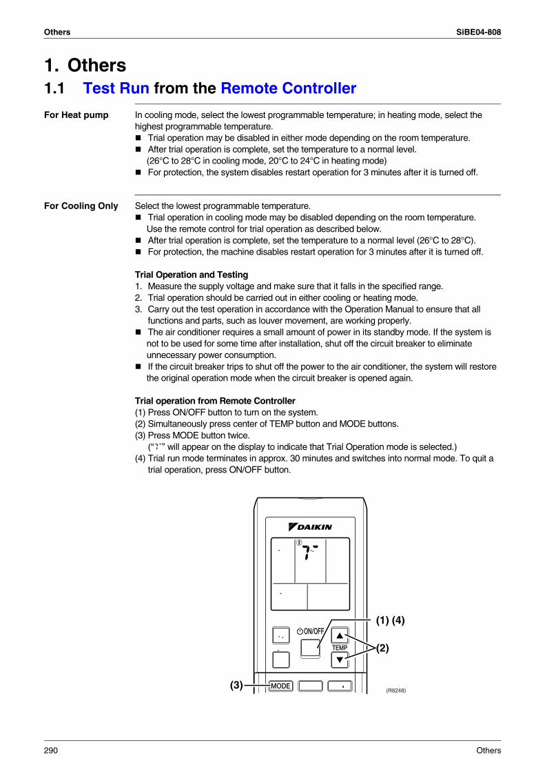
Others SiBE04-808
1. Others1.1 Test Run from the Remote Controller
For Heat pump In cooling mode, select the lowest programmable temperature; in heating mode, select the highest programmable temperature.
Trial operation may be disabled in either mode depending on the room temperature.After trial operation is complete, set the temperature to a normal level.(26°C to 28°C in cooling mode, 20°C to 24°C in heating mode)For protection, the system disables restart operation for 3 minutes after it is turned off.
For Cooling Only Select the lowest programmable temperature.Trial operation in cooling mode may be disabled depending on the room temperature. Use the remote control for trial operation as described below.After trial operation is complete, set the temperature to a normal level (26°C to 28°C).For protection, the machine disables restart operation for 3 minutes after it is turned off.
Trial Operation and Testing1. Measure the supply voltage and make sure that it falls in the specified range.2. Trial operation should be carried out in either cooling or heating mode.3. Carry out the test operation in accordance with the Operation Manual to ensure that all
functions and parts, such as louver movement, are working properly.The air conditioner requires a small amount of power in its standby mode. If the system is not to be used for some time after installation, shut off the circuit breaker to eliminate unnecessary power consumption.If the circuit breaker trips to shut off the power to the air conditioner, the system will restore the original operation mode when the circuit breaker is opened again.
Trial operation from Remote Controller(1) Press ON/OFF button to turn on the system.(2) Simultaneously press center of TEMP button and MODE buttons.(3) Press MODE button twice.
(“T” will appear on the display to indicate that Trial Operation mode is selected.)(4) Trial run mode terminates in approx. 30 minutes and switches into normal mode. To quit a
trial operation, press ON/OFF button.
(1) (4)
(2)
(3)(R8248)
290 Others
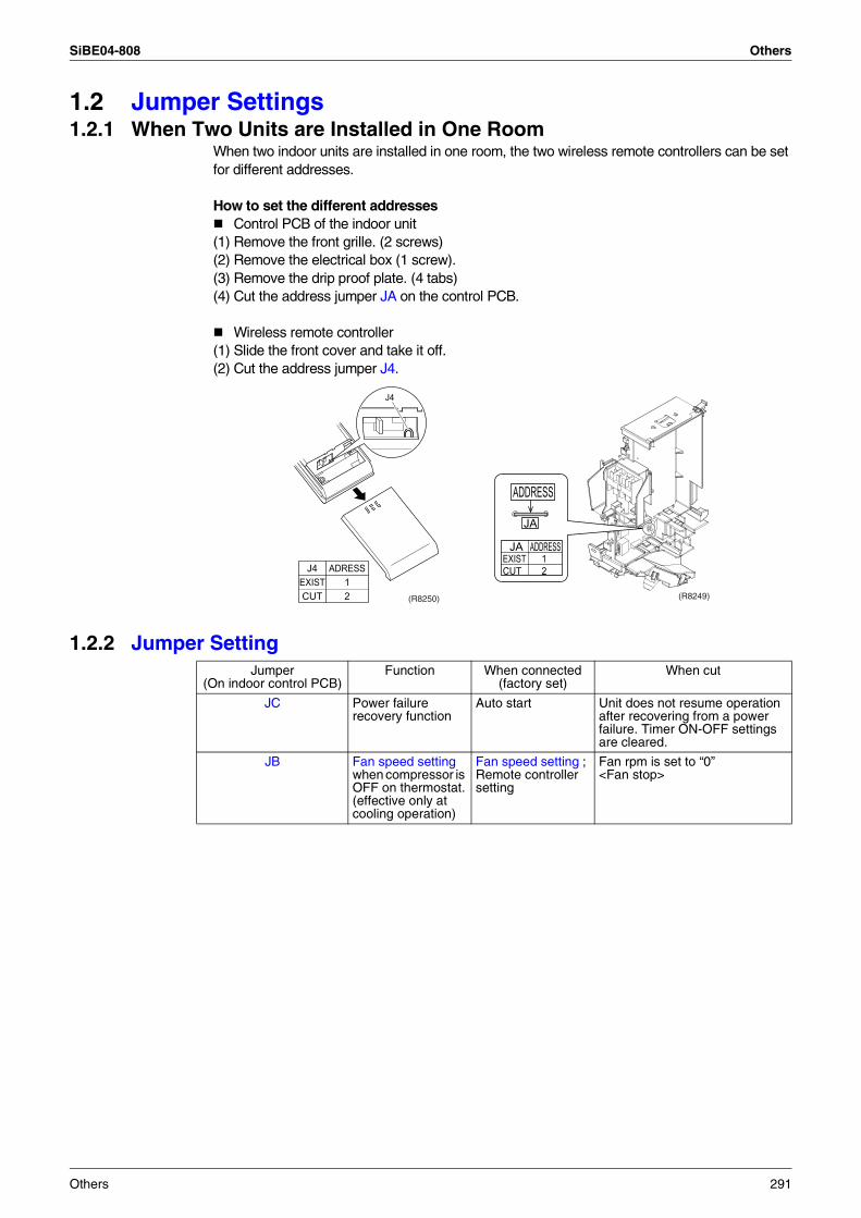
SiBE04-808 Others
1.2 Jumper Settings1.2.1 When Two Units are Installed in One Room
When two indoor units are installed in one room, the two wireless remote controllers can be set for different addresses.
How to set the different addressesControl PCB of the indoor unit
(1) Remove the front grille. (2 screws)(2) Remove the electrical box (1 screw).(3) Remove the drip proof plate. (4 tabs)(4) Cut the address jumper JA on the control PCB.
Wireless remote controller(1) Slide the front cover and take it off.(2) Cut the address jumper J4.
1.2.2 Jumper Setting
ADDRESS
JA
ADDRESSJAEXIST 1CUT 2
(R8249)
J4
J4 ADRESSEXIST 1CUT 2 (R8250)
Jumper (On indoor control PCB)
Function When connected (factory set)
When cut
JC Power failure recovery function
Auto start Unit does not resume operation after recovering from a power failure. Timer ON-OFF settings are cleared.
JB Fan speed setting when compressor is OFF on thermostat.(effective only at cooling operation)
Fan speed setting ; Remote controller setting
Fan rpm is set to “0” <Fan stop>
Others 291
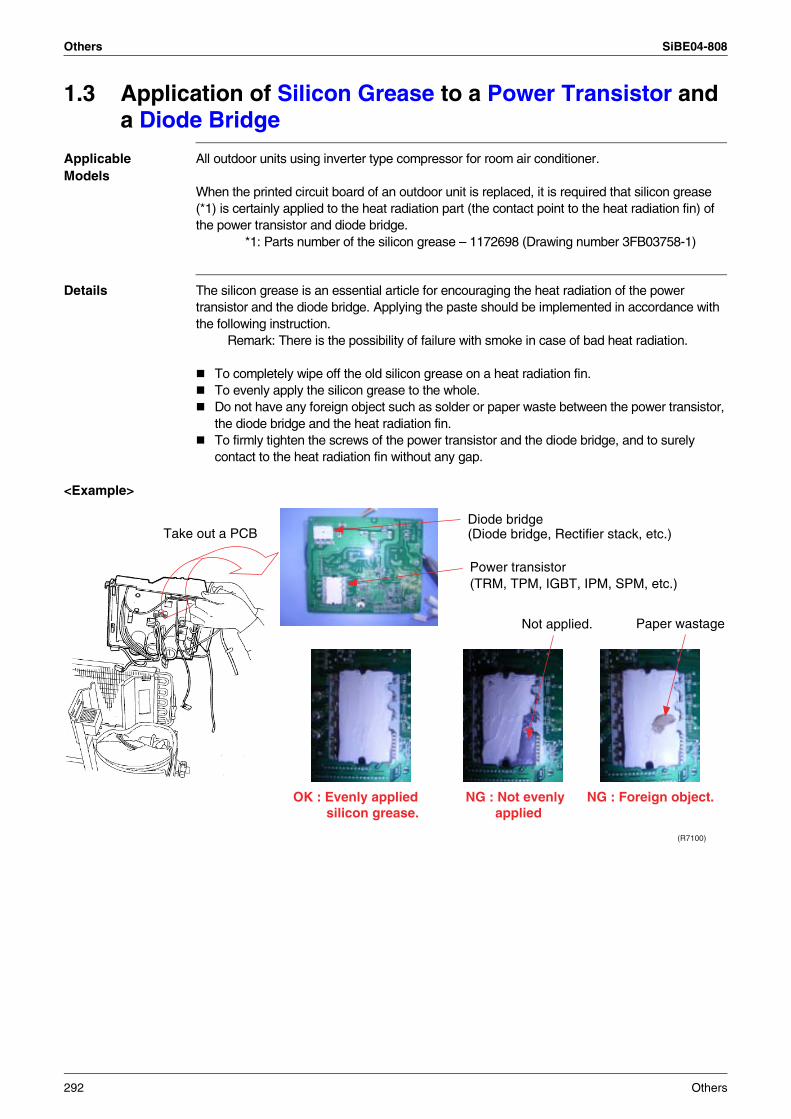
Others SiBE04-808
1.3 Application of Silicon Grease to a Power Transistor and a Diode Bridge
Applicable Models
All outdoor units using inverter type compressor for room air conditioner.
When the printed circuit board of an outdoor unit is replaced, it is required that silicon grease (*1) is certainly applied to the heat radiation part (the contact point to the heat radiation fin) of the power transistor and diode bridge. *1: Parts number of the silicon grease – 1172698 (Drawing number 3FB03758-1)
Details The silicon grease is an essential article for encouraging the heat radiation of the power transistor and the diode bridge. Applying the paste should be implemented in accordance with the following instruction. Remark: There is the possibility of failure with smoke in case of bad heat radiation.
To completely wipe off the old silicon grease on a heat radiation fin.To evenly apply the silicon grease to the whole.Do not have any foreign object such as solder or paper waste between the power transistor, the diode bridge and the heat radiation fin.To firmly tighten the screws of the power transistor and the diode bridge, and to surely contact to the heat radiation fin without any gap.
<Example>
Take out a PCBDiode bridge(Diode bridge, Rectifier stack, etc.)
Power transistor(TRM, TPM, IGBT, IPM, SPM, etc.)
Not applied. Paper wastage
OK : Evenly applied silicon grease.
NG : Not evenly applied
NG : Foreign object.
(R7100)
292 Others
SiBE04-808
Appendix 293
Part 9Appendix
1. Piping Diagrams..................................................................................2941.1 Indoor Units ..........................................................................................2941.2 Outdoor Units .......................................................................................295
2. Wiring Diagrams..................................................................................2992.1 Indoor Units ..........................................................................................2992.2 Outdoor Units .......................................................................................299
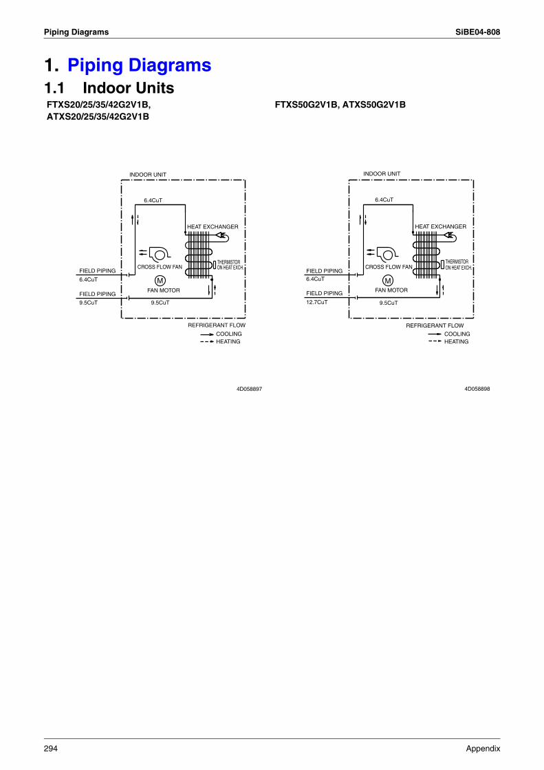
Piping Diagrams SiBE04-808
1. Piping Diagrams1.1 Indoor UnitsFTXS20/25/35/42G2V1B,ATXS20/25/35/42G2V1B
FTXS50G2V1B, ATXS50G2V1B
CROSS FLOW FAN
9.5CuT
REFRIGERANT FLOW
FIELD PIPING
9.5CuT
6.4CuT
FIELD PIPING
M
COOLING
THERMISTORON HEAT EXCH.
INDOOR UNIT
FAN MOTOR
HEAT EXCHANGER
6.4CuT
HEATING
4D058897
CROSS FLOW FAN
COOLING
9.5CuT
6.4CuT
M
INDOOR UNIT
6.4CuT
REFRIGERANT FLOW
HEATING
FAN MOTORFIELD PIPING
HEAT EXCHANGER
THERMISTORON HEAT EXCH.
FIELD PIPING
12.7CuT
4D058898
294 Appendix
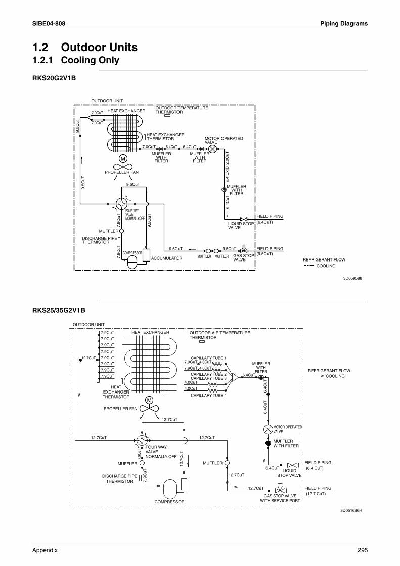
SiBE04-808 Piping Diagrams
1.2 Outdoor Units1.2.1 Cooling Only
RKS20G2V1B
RKS25/35G2V1B
9.5CuT
OUTDOOR TEMPERATURETHERMISTOR
7.0CuT
HEAT EXCHANGERTHERMISTOR
(6.4CuT)LIQUID STOPVALVE
GAS STOPVALVE
9.5C
uT
6.4C
uT
7.0CuT
ACCUMULATOR
MUFFLERWITH
FILTER
MUFFLERWITH
FILTER
FIELD PIPING
FOUR WAYVALVENORMALLY:OFF
9.5C
uT
7.9C
uT
(9.5CuT)MUFFLERMUFFLER
9.5CuT
7.0CuT
DISCHARGE PIPETHERMISTOR
HEAT EXCHANGER
6.4CuT
M
COOLING
OUTDOOR UNIT
MUFFLER
COMPRESSOR
MUFFLERWITH
FILTER
9.5CuT
PROPELLER FAN
FIELD PIPING
6.4CuT
REFRIGERANT FLOW
7.9C
uT
MOTOR OPERATEDVALVE
9.5C
uT
φ.4.
0×ID
. 2.0
CuT
3D059588
OUTDOOR UNIT
12.7CuT
12.7CuT
7.9CuT
7.9CuT
7.9CuT
7.9CuT
7.9CuT
7.9CuT
7.9CuT
7.9CuT
DISCHARGE PIPETHERMISTOR
HEATEXCHANGERTHERMISTOR
PROPELLER FAN
MUFFLER
HEAT EXCHANGER
7.9C
uT7.
9CuT
M
COMPRESSOR
FOUR WAYVALVENORMALLY:OFF
12.7CuT
12.7
CuT
OUTDOOR AIR TEMPERATURETHERMISTOR
7.9CuT
7.9CuT
4.0CuT
4.0CuT
CAPILLARY TUBE 4
CAPILLARY TUBE 2CAPILLARY TUBE 3
CAPILLARY TUBE 1
12.7CuT
MUFFLER
12.7CuT
6.4CuT
12.7CuT
MUFFLERWITH
FILTER
6.4CuT
6.4C
uT6.
4CuT
GAS STOP VALVEWITH SERVICE PORT
MUFFLERWITH FILTER
MOTOR OPERATEDVALVE
LIQUIDSTOP VALVE
FIELD PIPING
REFRIGERANT FLOW
FIELD PIPING(12.7 CuT)
(6.4 CuT)
COOLING
4.0CuT
4.0CuT
3D051636H
Appendix 295
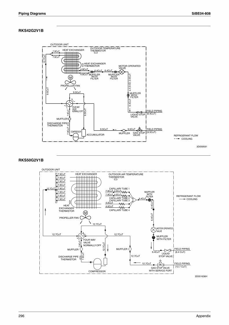
Piping Diagrams SiBE04-808
RKS42G2V1B
RKS50G2V1B
FOUR WAYVALVENORMALLY:OFF
REFRIGERANT FLOW
6.4CuT
COMPRESSOR9.5CuT
7.9C
uT
MUFFLERWITH
FILTER
9.5CuT
9.5CuT
PROPELLER FAN
OUTDOOR UNIT
MUFFLERWITH
FILTERM
MUFFLER (9.5CuT)ACCUMULATOR
(6.4CuT)
4.8CuT
9.5C
uT
9.5C
uT
FIELD PIPING
HEAT EXCHANGEROUTDOOR TEMPERATURETHERMISTOR7.9CuT
MUFFLERWITH
FILTER
4.8CuT
DISCHARGE PIPETHERMISTOR
MOTOR OPERATEDVALVE
MUFFLER
12.7
CuT
GAS STOPVALVE
7.9C
uT FIELD PIPING
6.4C
uT
7.9CuT
COOLING
LIQUID STOPVALVE
HEAT EXCHANGERTHERMISTOR
6.4CuT
φ.4.
0×ID
. 2.0
CuT
3D059591
OUTDOOR UNIT
12.7CuT
12.7CuT
7.9CuT
7.9CuT
7.9CuT
7.9CuT
7.9CuT
7.9CuT
7.9CuT
7.9CuT
DISCHARGE PIPETHERMISTOR
HEATEXCHANGERTHERMISTOR
PROPELLER FAN
MUFFLER
HEAT EXCHANGER
7.9C
uT7.
9CuT
M
COMPRESSOR
FOUR WAYVALVENORMALLY:OFF
12.7CuT
12.7
CuT
OUTDOOR AIR TEMPERATURETHERMISTOR
7.9CuT
7.9CuT
4.0CuT
4.0CuT
CAPILLARY TUBE 4
CAPILLARY TUBE 2CAPILLARY TUBE 3
CAPILLARY TUBE 1
12.7CuT
MUFFLER
12.7CuT
6.4CuT
12.7CuT
MUFFLERWITH
FILTER
6.4CuT
6.4C
uT6.
4CuT
GAS STOP VALVEWITH SERVICE PORT
MUFFLERWITH FILTER
MOTOR OPERATEDVALVE
LIQUIDSTOP VALVE
FIELD PIPING
REFRIGERANT FLOW
FIELD PIPING(12.7 CuT)
(6.4 CuT)
COOLING
4.0CuT
4.0CuT
3D051636H
296 Appendix
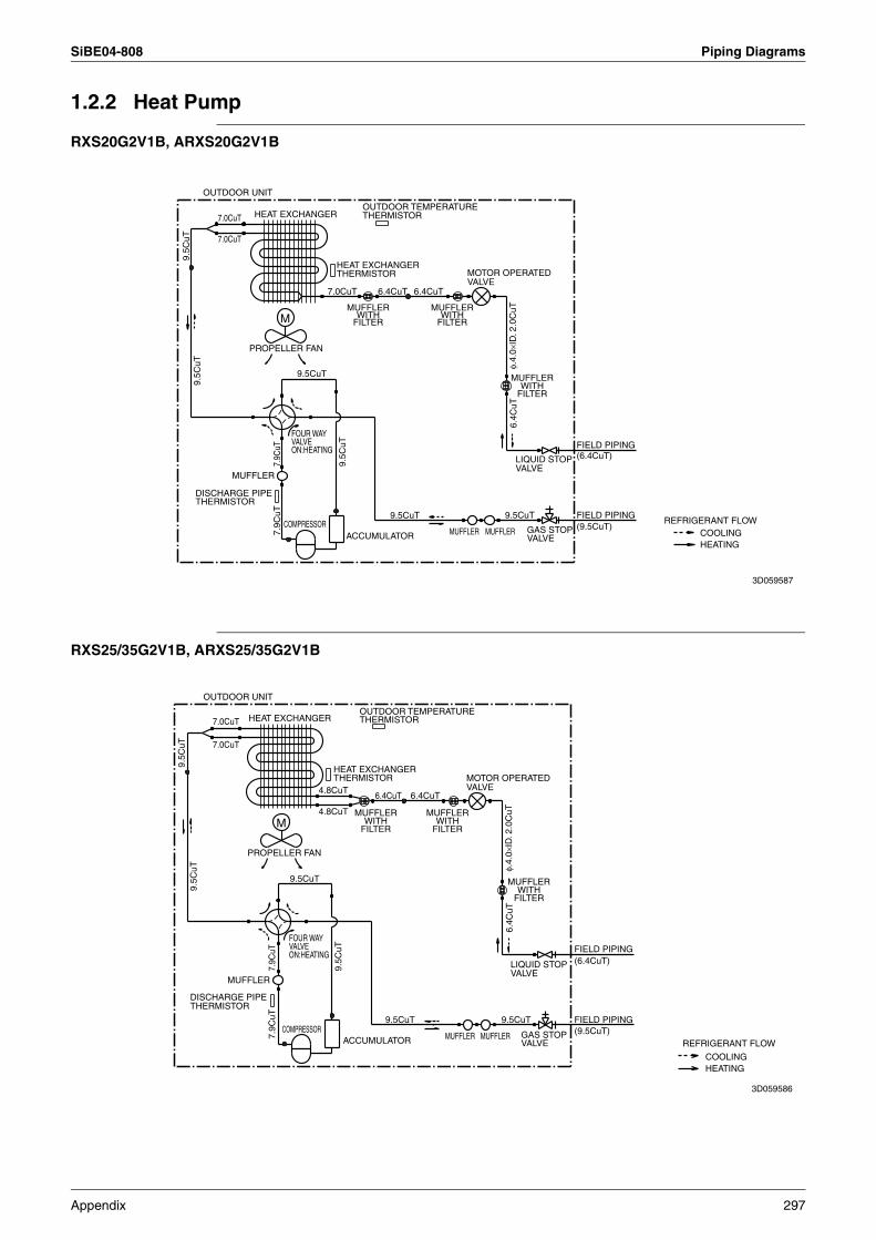
SiBE04-808 Piping Diagrams
1.2.2 Heat Pump
RXS20G2V1B, ARXS20G2V1B
RXS25/35G2V1B, ARXS25/35G2V1B
MOTOR OPERATEDVALVE
6.4CuT
OUTDOOR UNIT
DISCHARGE PIPETHERMISTOR
M
MUFFLER
7.0CuT
MUFFLER
MUFFLERWITH
FILTER
6.4C
uT
9.5C
uT
ACCUMULATOR
FIELD PIPING
7.9C
uT
9.5C
uT
7.0CuT
9.5C
uT
REFRIGERANT FLOW
FOUR WAYVALVEON:HEATING
9.5CuT
HEATING
7.0CuT
GAS STOPVALVE
9.5CuT
LIQUID STOPVALVE
MUFFLERCOMPRESSOR
MUFFLERWITH
FILTER
(6.4CuT)
6.4CuT
(9.5CuT)COOLING
HEAT EXCHANGERTHERMISTOR
7.9C
uT
OUTDOOR TEMPERATURETHERMISTORHEAT EXCHANGER
PROPELLER FAN
FIELD PIPING
MUFFLERWITH
FILTER
9.5CuTφ.
4.0×
ID. 2
.0C
uT
3D059587
MUFFLERWITH
FILTER
7.9C
uT
(9.5CuT)7.9C
uT
7.0CuT
LIQUID STOPVALVE
M
HEAT EXCHANGER
MUFFLER
MUFFLERWITH
FILTER
HEAT EXCHANGERTHERMISTOR
6.4C
uT
FIELD PIPING
9.5CuT
HEATING
6.4CuT
FIELD PIPING
9.5CuT
6.4CuT
MUFFLER
9.5CuT
DISCHARGE PIPETHERMISTOR
REFRIGERANT FLOW
7.0CuT
COOLING
GAS STOPVALVE
φ.4.
0×ID
. 2.0
CuT4.8CuT
PROPELLER FAN
COMPRESSOR
OUTDOOR UNIT
MUFFLERWITH
FILTER
OUTDOOR TEMPERATURETHERMISTOR
9.5C
uT
(6.4CuT)
4.8CuT
9.5C
uT
MOTOR OPERATEDVALVE
MUFFLERACCUMULATOR
FOUR WAYVALVEON:HEATING
9.5C
uT
3D059586
Appendix 297
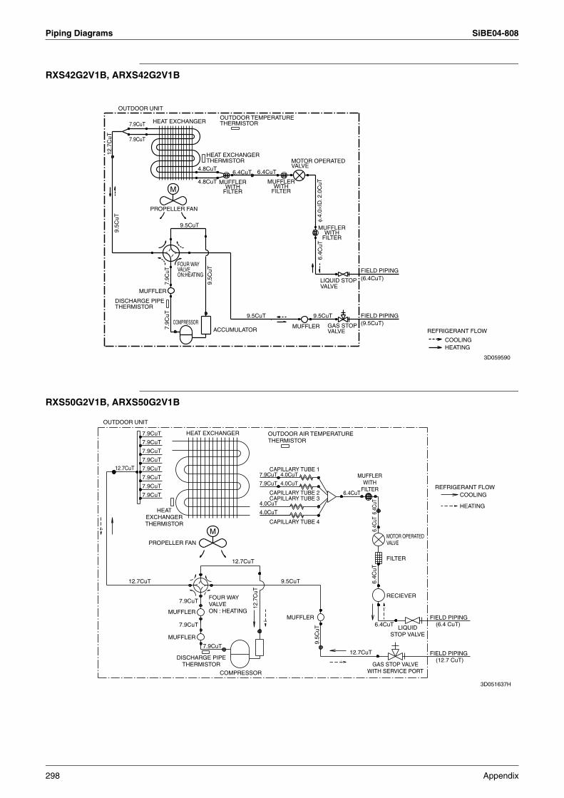
Piping Diagrams SiBE04-808
RXS42G2V1B, ARXS42G2V1B
RXS50G2V1B, ARXS50G2V1B
FIELD PIPING
FOUR WAYVALVEON:HEATING
DISCHARGE PIPETHERMISTOR
MUFFLERWITH
FILTER
9.5CuT
4.8CuT
4.8CuT6.4CuT
MUFFLER
MOTOR OPERATEDVALVE
9.5C
uTPROPELLER FAN
7.9CuT
7.9C
uT
9.5CuT
GAS STOPVALVE
6.4CuT
MUFFLERWITH
FILTER
OUTDOOR TEMPERATURETHERMISTOR
ACCUMULATORMUFFLER7.
9CuT
COOLING
HEAT EXCHANGER
HEAT EXCHANGERTHERMISTOR
FIELD PIPING
6.4C
uT9.5CuT
OUTDOOR UNIT12
.7C
uT
(6.4CuT)
MUFFLERWITH
FILTER
REFRIGERANT FLOW
9.5C
uT
HEATING
(9.5CuT)
LIQUID STOPVALVE
7.9CuT
COMPRESSOR
M
φ.4.
0×ID
. 2.0
CuT
3D059590
OUTDOOR UNIT
12.7CuT
12.7CuT
7.9CuT
7.9CuT
7.9CuT
7.9CuT
7.9CuT
7.9CuT
7.9CuT
7.9CuT
DISCHARGE PIPETHERMISTOR
HEATEXCHANGERTHERMISTOR
PROPELLER FAN
MUFFLER
HEAT EXCHANGER
7.9CuT
7.9CuT
M
FOUR WAYVALVEON : HEATING
COMPRESSOR
12.7CuT
12.7
CuT
OUTDOOR AIR TEMPERATURETHERMISTOR
7.9CuT
7.9CuT
4.0CuT
4.0CuT
CAPILLARY TUBE 4
CAPILLARY TUBE 2CAPILLARY TUBE 3
CAPILLARY TUBE 1
9.5CuT
MUFFLER
9.5C
uT
6.4CuT
12.7CuT
MUFFLERWITH
FILTER
6.4CuT
6.4C
uT6.
4CuT
6.4C
uT
GAS STOP VALVEWITH SERVICE PORT
FILTER
MOTOR OPERATEDVALVE
RECIEVER
LIQUIDSTOP VALVE
FIELD PIPING
FIELD PIPING
REFRIGERANT FLOW
(12.7 CuT)
(6.4 CuT)
HEATING
COOLING
4.0CuT
4.0CuT
7.9CuT
MUFFLER
3D051637H
298 Appendix
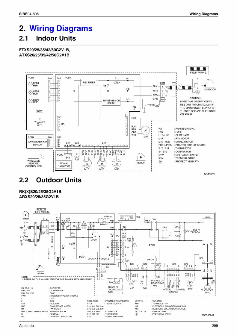
SiBE04-808 Wiring Diagrams
2. Wiring Diagrams2.1 Indoor Units
FTXS20/25/35/42/50G2V1B,ATXS20/25/35/42/50G2V1B
2.2 Outdoor Units
RK(X)S20/25/35G2V1B,ARXS20/25/35G2V1B
M
MM M
X1M
LED3H3P
ON AGAIN.
CAUTION
THE MAIN POWER SUPPLY ISTURNED OFF AND THEN BACK
RESTART AUTOMATICALLY IFNOTE THAT OPERATION WILL
S1W
TRANSMISSIONCIRCUIT
LED2H2P
3.15A
SIGNALRECEIVER
RECTIFIER
2
3
1
INDOOR
OUTDOOR
FIELD WIRING.
INTELLIGENT EYESENSOR
LED1H1P
WHT
S47
F1U
S32
ORG
/Y
LW
M3S
t˚
H3
2
YLW
PN
K
H1
GRN
S26
S21S1
RED
PCB1
S41
PCB4
OR
G
YLW
S48t˚
M1S
BLU
H2
M1F
WHT
BLU
PCB3
R1T
S46
WIRELESSREMOTE
CONTROLLER
PN
K
OR
GBLK
S49
RE
D
OR
G
3
YLW
M2S
GRN
PN
K
BLU
S25
RE
D
1
BLU
V1
RED
BRN
HA
R2T
RE
D
FG
PCB2
~ ~
FGF1UH1P~H3PM1FM1S~M3SPCB1~PCB4R1T, R2TS1~S49S1W
: SWING MOTOR
: THERMISTOR
: FRAME GROUND: FUSE: PILOT LAMP: FAN MOTOR
: PRINTED CIRCUIT BOARD
: CONNECTOR: OPERATION SWITCH
: PROTECTIVE EARTHX1M : TERMINAL STRIP
3D058246
L
N
2
1
3
MRM10
S20
indoor
N=2Z2C
L1R
1. REFER TO THE NAMEPLATE FOR THE POWER REQUIREMENTS.NOTE
outdoor
S90
C118
S40
FIELD WIRING.
S50
ORG
BLU
RED
BRN
WHT
M1~
C5
C6
MRM20
E1
S8031
IN CASE OFCOOLING ONLYTYPE
GRN
E2
GRN
/YLW
BLK
BLK
S10
BLK
BLK
BLK
BLKBLK
WHT1BLK
1
S11
9 9
C5, C6, C118 : CAPACITOR R1T
2
YLW
Y1R : REVERSING SOLENOIDE VALVE COIL
MR30
V
W
WHT
20A
6
X1M : TERMINAL STRIP
WHT
S70
DB1
V1
FU1
3.15A
1
PCB2
2 3
Y1E
1
S30
RED
Q1L
S10, S11, S20, S30,S40, S50, S70, S80,S90, HL3, HN3 : CONNECTOR
4
PTC1 : THERMISTOR PTC
YLW
BLK
BLK
Z1C
(OUTDOOR)
BLU
12
V3
HR1ORG
1
IPM1 : INTELLIGENT POWER MODULE
BLK
HN3
BRN
S
BLK
HL3
HR2
GRY
1
3
SA1
BLK
3.15A
N=1
S80
M1C : COMPRESSOR MOTOR
L1 : COIL
U
IPM1
PCB1
BLK
Z3C
BRN
FU2
HL2
2
1
: PROTECTIVE EARTHN : NEUTRAL
R2TM1F
AC1
DB1, DB2 : DIODE BRIDGE
YLW
X1M
1BRN
PCB1, PCB2 : PRINTED CIRCUIT BOARDL : LIVE
7
BLK
Y1E : ELECTRONIC EXPANSION VALVE COIL
MRCW
L1R : REACTOR
1
ORG
AC2
U
V2
RED
N
Y1R
M
M1C
W
BLK
R1T, R2T, R3T : THERMISTOR
(DISCHARGE)
ORG
MR30_A
N=4
HN2
(CONDENSER)
BLK
BLU
L
GRYBL
U
BLK
6
FU3
BLK
MR30_B
DB2
IN CASE OFHEAT PUMPTYPE
3
L1
MRCW, MR30, MRM10, MRM20 : MAGNETIC RELAY
V
FU1, FU2, FU3 : FUSE
RED
4
Q1L : OVERLOAD PROTECTOR SA1 : SURGE ARRESTER
V1,V2,V3 : VARISTOR
1
M1F : FAN MOTOR
R3T
BLK
3
Z1C, Z2C, Z3C : FERRITE CORE
~
~
+
_~
~
+
_
+_
+_
+_
+
_
t˚ t˚ t˚
3D058684A
Appendix 299
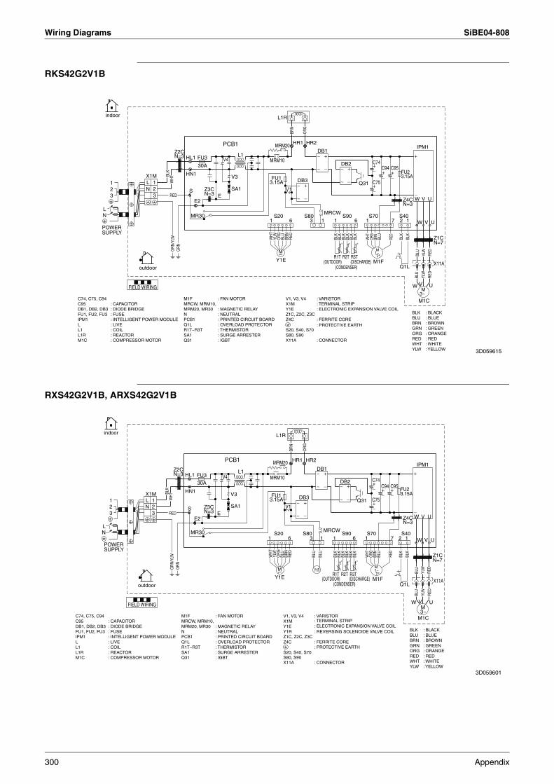
Wiring Diagrams SiBE04-808
RKS42G2V1B
RXS42G2V1B, ARXS42G2V1B
1 U
YLW
M1C
Z2C
BLK
WHT
N
SE
WHT
V1
Z4CN=3
RED
GRN
/YLW BL
K
Q31
3~
S40
R1T
2
C94
W
BLK
FU23.15A
3 RED
HL1
UBL
U
(DISCHARGE)
BLK
M
1S90
(CONDENSER)
3
DB3
6S20
MRM20
BLU
POWERSUPPLY
RED
1
HN1
HR1
L
1
2
YLW
W U
W
Q1L
V
R2T
3
C751
C7430A
N=3
ORG
L1R
ORG
DB1
BLU
R3T
MR30
FIELD WIRING
(OUTDOOR)
BLU
outdoor
N
WHT
V
SA1
RED
FU3
BLK
MRCW
C95
E2
RED
Y1E
BLK
GRN
6 1
L1
V
ORG
1
S80
X11A
S70
PCB1
M
BRN
X1M
YLW
MRM10
2
Z3C
N=3
3.15A
N=7
LFU1
BRN
Z1C
BLK
1~
M
M1F
V3
IPM1
DB2
indoor
BLK
BRN
7
HR2
V4
BLK
~
~
+
_
~
~
+
_ ~
~
+
_
+_
+_
+_
+_
+
_
t˚ t˚ t˚
M1F : FAN MOTORMRCW, MRM10,MRM20, MR30 : MAGNETIC RELAYN : NEUTRALPCB1 : PRINTED CIRCUIT BOARDQ1L : OVERLOAD PROTECTORR1T~R3T : THERMISTORSA1 : SURGE ARRESTERQ31 : IGBT
C74, C75, C94C95 : CAPACITORDB1, DB2, DB3 : DIODE BRIDGEFU1, FU2, FU3 : FUSEIPM1 : INTELLIGENT POWER MODULEL : LIVEL1 : COILL1R : REACTORM1C : COMPRESSOR MOTOR
V1, V3, V4 : VARISTORX1M : TERMINAL STRIPY1E : ELECTRONIC EXPANSION VALVE COILZ1C, Z2C, Z3CZ4C : FERRITE CORE
: PROTECTIVE EARTHS20, S40, S70S80, S90X11A : CONNECTOR
BLK : BLACKBLU : BLUEBRN : BROWNGRN : GREENORG : ORANGERED : REDWHT : WHITEYLW : YELLOW 3D059615
MRM10
BRN
M1F : FAN MOTORMRCW, MRM10,MRM20, MR30 : MAGNETIC RELAYN : NEUTRALPCB1 : PRINTED CIRCUIT BOARDQ1L : OVERLOAD PROTECTORR1T~R3T : THERMISTORSA1 : SURGE ARRESTERQ31 : IGBT
HL1
YLW
YLW
V
HR2
(CONDENSER)
BLK
S20
2
BLU
BLK
FU23.15A
R2T
V3
S90
DB2
W
BLK
DB3
Q1L
6
L
M1F
E
FU1
BRN
MR3T
Z1CORG
V1
FU3
RED
V
BLK
X11A
MRM20 HR1
1
Z2C
3
S80
1
N=3
S N=3
RED
HN1
S70
BLK
RED
N=7
30A
Z4C
3~
IPM1
C95
L1R
BRN
M1C
V4
MR30
E2
C94
N
BLK
C74, C75, C94C95 : CAPACITORDB1, DB2, DB3 : DIODE BRIDGEFU1, FU2, FU3 : FUSEIPM1 : INTELLIGENT POWER MODULEL : LIVEL1 : COILL1R : REACTORM1C : COMPRESSOR MOTOR
M
WM
R1T
L1
1
indoorRE
D
WHT
SA1
WHT
3
BLK
YLW
GRN
/YLW
DB1
ORG
Z3C
V1, V3, V4 : VARISTORX1M : TERMINAL STRIPY1E : ELECTRONIC EXPANSION VALVE COILY1R : REVERSING SOLENOIDE VALVE COILZ1C, Z2C, Z3CZ4C : FERRITE CORE
: PROTECTIVE EARTHS20, S40, S70S80, S90X11A : CONNECTOR
Y1R
C75L
outdoor(OUTDOOR)
PCB1
N
BLU
1
BLU
(DISCHARGE)
WHT
Q31
U3 11
3.15A
2POWERSUPPLY
N=3
X1M
2
W6
FIELD WIRING
C74
1~ BLU
U
BLK
U
BLK
RED
S40MRCW
GRN
BLU
Y1E
1
7
BLU
V
ORG
BLK : BLACKBLU : BLUEBRN : BROWNGRN : GREENORG : ORANGERED : REDWHT : WHITEYLW : YELLOW
~
~
+
_ ~
~
+
_~
~
+
_
+_
+_
+_
+_
+
_
t˚ t˚ t˚
3D059601
300 Appendix
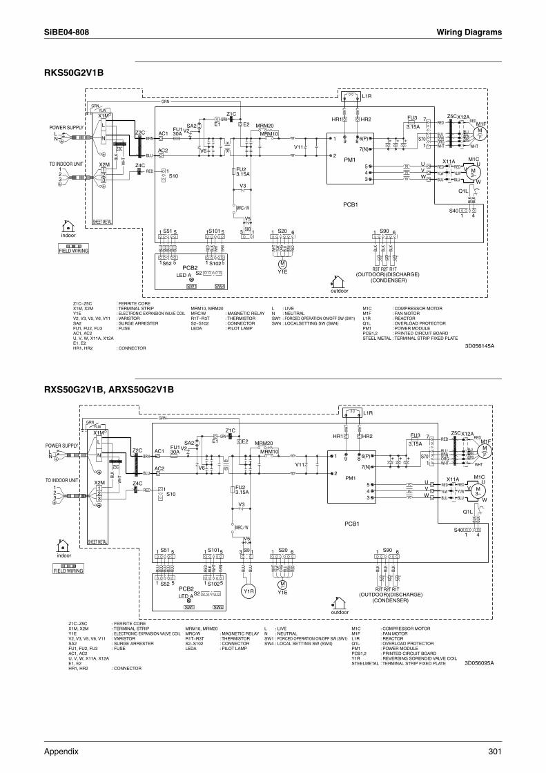
SiBE04-808 Wiring Diagrams
RKS50G2V1B
RXS50G2V1B, ARXS50G2V1B
outdoor
FIELD WIRING
indoor
S2
BLU
BRN
FU3
1
3.15A
1
WHT
TO INDOOR UNIT
BLU
8
POWER SUPPLY
YLW
BLK
BRN
BRN
FU1MRM10
S10
1
3 BLU
5
BLU
V6
SHEET METAL
7
V3
YLW
RED
S40
AC1
BLK
Z3C
MRM10, MRM20MRC/W : MAGNETIC RELAYR1T~R3T : THERMISTORS2~S102 : CONNECTORLEDA : PILOT LAMP
GRN
BLU
6(P)BRN
M
Z5C
PCB1
1 S102
WHT
1Z4C
BLK
L
BLU
5
SW4
M1F
3
N
E1
2
6
2
1
E2
4
ORG
BLK
3
FU2
R2T
BLK
V2 BLU
(CONDENSER)
M1CPM1
YLWV
WHT
V5
M1C : COMPRESSOR MOTORM1F : FAN MOTORL1R : REACTORQ1L : OVERLOAD PROTECTORPM1 : POWER MODULEPCB1,2 : PRINTED CIRCUIT BOARDSTEEL METAL
WHT
S90
LED A
BLU
L
1
4
(OUTDOOR)(DISCHARGE)
3
27(N)
GRN
U
Q1L
1 1
RED
1
HR2
M3~
RED V
S101
ORG
X11A
1
Z1C
WHT
L : LIVEN : NEUTRALSW1 : FORCED OPERATION ON/OFF SW (SW1)SW4 : LOCALSETTING SW (SW4)
9N
Z1C~Z5C : FERRITE COREX1M, X2M : TERMINAL STRIPY1E : ELECTRONIC EXPANSION VALVE COILV2, V3, V5, V6, V11 : VARISTORSA2 : SURGE ARRESTERFU1, FU2, FU3 : FUSEAC1, AC2U, V, W, X11A, X12AE1, E2HR1, HR2 : CONNECTOR
R1T
U
YLW
V11
PCB2
5BL
U
MRC
L1RGRN
HR1
S801
S52
W
RED
M
6
WHT
GRN
RED3.15A
30A
BLK
MRM20
X1M
BLU
S51
W
WHT
RED
BLU
S20
W
X2M
5
X12A
1
BLK
SW1
ORG
AC2
Y1E
S70
R3T
SA2
5
Z2C
RED
: TERMINAL STRIP FIXED PLATE
t° t° t°
+ + +
3D056145A
outdoor
SA2
FIELD WIRING
YLWGRN
SHEET METAL
X1M
indoor
4
WHT
5
E2
BLK
S90
3.15A
BLU
1
U
BRN
SW4
R3TS2
3 W
HR1
6
PCB2
Z2C
(OUTDOOR)(DISCHARGE)
E1
Z3C
V2
ORG
1Z4C
2FU2
N
M
ORGBRN
3
(CONDENSER)
S20
POWER SUPPLY
6
X11A
N
1
1
BLK
U
BLU
YLW
BLU
LED A
30A
BLU
M
BRN
V3
Y1R R1T
MRC
WHT
GRN
TO INDOOR UNIT
V3~
1 VS10
BLU
M1C
M1F
BLK
1
FU3 RED
5
6(P)
1
ORG
X12A
1
S40
PM1
HR2
S102
AC2
REDRED
BLUV6 7(N)
BLU
5
L
RED
AC1
MRM20
1 1
SW1
YLW
WHT
S101
BLU
MRM10 BLU
5
Q1L
RED
L
Z5C
BLU
3.15A
YLW
89
X2M
PCB1
V5
S80
WHT
RED
BRN
M
BLU
BLK
WHT
FU1
S70
S52R2T
1
GRN
WHT
3
WHT
W
BLU
W
L1R
V11
3
RED
BLU
BLK
1
4
BLK
GRN
2
2
51 S51
Z1C
BLK
7
Y1E
MRM10, MRM20MRC/W : MAGNETIC RELAYR1T~R3T : THERMISTORS2~S102 : CONNECTORLEDA : PILOT LAMP
M1C : COMPRESSOR MOTORM1F : FAN MOTORL1R : REACTORQ1L : OVERLOAD PROTECTORPM1 : POWER MODULEPCB1,2 : PRINTED CIRCUIT BOARD
STEELMETAL
L : LIVEN : NEUTRALSW1 : FORCED OPERATION ON/OFF SW (SW1)SW4 : LOCAL SETTING SW (SW4)
Z1C~Z5C : FERRITE COREX1M, X2M : TERMINAL STRIPY1E : ELECTRONIC EXPANSION VALVE COILV2, V3, V5, V6, V11 : VARISTORSA2 : SURGE ARRESTERFU1, FU2, FU3 : FUSEAC1, AC2U, V, W, X11A, X12AE1, E2HR1, HR2 : CONNECTOR
: TERMINAL STRIP FIXED PLATEY1R : REVERSING SORENOID VALVE COIL
t° t° t°
+ + +
3D056095A
Appendix 301
Wiring Diagrams SiBE04-808
302 Appendix
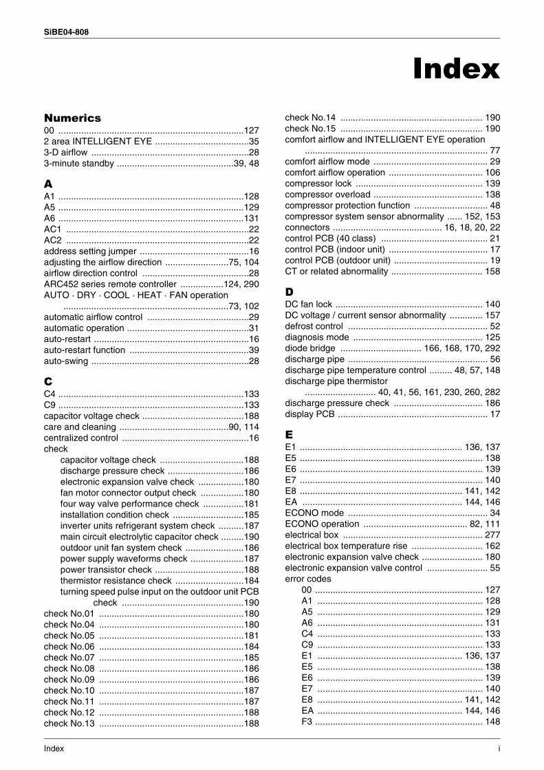
SiBE04-808
IndexNumerics00 .........................................................................1272 area INTELLIGENT EYE .....................................353-D airflow ..............................................................283-minute standby ..............................................39, 48
AA1 .........................................................................128A5 .........................................................................129A6 .........................................................................131AC1 ........................................................................22AC2 ........................................................................22address setting jumper ...........................................16adjusting the airflow direction .........................75, 104airflow direction control ..........................................28ARC452 series remote controller .................124, 290AUTO · DRY · COOL · HEAT · FAN operation
.................................................................73, 102automatic airflow control ........................................29automatic operation ................................................31auto-restart .............................................................16auto-restart function ...............................................39auto-swing ..............................................................28
CC4 .........................................................................133C9 .........................................................................133capacitor voltage check ........................................188care and cleaning ...........................................90, 114centralized control ..................................................16check
capacitor voltage check .................................188discharge pressure check ..............................186electronic expansion valve check ..................180fan motor connector output check .................180four way valve performance check ................181installation condition check ............................185inverter units refrigerant system check ..........187main circuit electrolytic capacitor check .........190outdoor unit fan system check .......................186power supply waveforms check .....................187power transistor check ...................................188thermistor resistance check ...........................184turning speed pulse input on the outdoor unit PCB
check ................................................190check No.01 .........................................................180check No.04 .........................................................180check No.05 .........................................................181check No.06 .........................................................184check No.07 .........................................................185check No.08 .........................................................186check No.09 .........................................................186check No.10 .........................................................187check No.11 .........................................................187check No.12 .........................................................188check No.13 .........................................................188
check No.14 ........................................................ 190check No.15 ........................................................ 190comfort airflow and INTELLIGENT EYE operation
........................................................................ 77comfort airflow mode ............................................. 29comfort airflow operation ..................................... 106compressor lock .................................................. 139compressor overload ........................................... 138compressor protection function ............................. 48compressor system sensor abnormality ...... 152, 153connectors ........................................... 16, 18, 20, 22control PCB (40 class) .......................................... 21control PCB (indoor unit) ....................................... 17control PCB (outdoor unit) ..................................... 19CT or related abnormality .................................... 158
DDC fan lock .......................................................... 140DC voltage / current sensor abnormality ............. 157defrost control ....................................................... 52diagnosis mode ................................................... 125diode bridge ................................ 166, 168, 170, 292discharge pipe ....................................................... 56discharge pipe temperature control ......... 48, 57, 148discharge pipe thermistor
............................ 40, 41, 56, 161, 230, 260, 282discharge pressure check ................................... 186display PCB ........................................................... 17
EE1 ................................................................ 136, 137E5 ........................................................................ 138E6 ........................................................................ 139E7 ........................................................................ 140E8 ................................................................ 141, 142EA ............................................................... 144, 146ECONO mode ....................................................... 34ECONO operation ......................................... 82, 111electrical box ....................................................... 277electrical box temperature rise ............................ 162electronic expansion valve check ........................ 180electronic expansion valve control ........................ 55error codes
00 .................................................................. 127A1 ................................................................. 128A5 ................................................................. 129A6 ................................................................. 131C4 ................................................................. 133C9 ................................................................. 133E1 ......................................................... 136, 137E5 ................................................................. 138E6 ................................................................. 139E7 ................................................................. 140E8 ......................................................... 141, 142EA ......................................................... 144, 146F3 .................................................................. 148
Index i
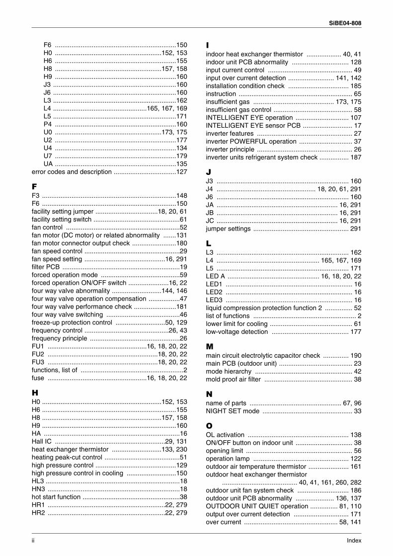
SiBE04-808
F6 ..................................................................150H0 ..........................................................152, 153H6 ..................................................................155H8 ..........................................................157, 158H9 ..................................................................160J3 ...................................................................160J6 ...................................................................160L3 ...................................................................162L4 ...................................................165, 167, 169L5 ...................................................................171P4 ..................................................................160U0 ..........................................................173, 175U2 ..................................................................177U4 ..................................................................134U7 ..................................................................179UA ..................................................................135
error codes and description ..................................127
FF3 .........................................................................148F6 .........................................................................150facility setting jumper ..................................18, 20, 61facility setting switch ...............................................61fan control ..............................................................52fan motor (DC motor) or related abnormality .......131fan motor connector output check ........................180fan speed control ....................................................29fan speed setting ............................................16, 291filter PCB ................................................................19forced operation mode ...........................................59forced operation ON/OFF switch ......................16, 22four way valve abnormality ...........................144, 146four way valve operation compensation .................47four way valve performance check .......................181four way valve switching ........................................46freeze-up protection control ...........................50, 129frequency control ..............................................26, 43frequency principle .................................................26FU1 ......................................................16, 18, 20, 22FU2 ............................................................18, 20, 22FU3 ............................................................18, 20, 22functions, list of ........................................................2fuse ......................................................16, 18, 20, 22
HH0 .................................................................152, 153H6 .........................................................................155H8 .................................................................157, 158H9 .........................................................................160HA ..........................................................................16Hall IC ............................................................29, 131heat exchanger thermistor ...........................133, 230heating peak-cut control .........................................51high pressure control ............................................129high pressure control in cooling ...........................150HL3 .........................................................................18HN3 ........................................................................18hot start function .....................................................38HR1 ................................................................22, 279HR2 ................................................................22, 279
Iindoor heat exchanger thermistor ................... 40, 41indoor unit PCB abnormality ............................... 128input current control .............................................. 49input over current detection ......................... 141, 142installation condition check ................................. 185instruction .............................................................. 65insufficient gas ............................................ 173, 175insufficient gas control ........................................... 58INTELLIGENT EYE operation ............................. 107INTELLIGENT EYE sensor PCB ........................... 17inverter features .................................................... 27inverter POWERFUL operation ............................. 37inverter principle .................................................... 26inverter units refrigerant system check ................ 187
JJ3 ........................................................................ 160J4 ...................................................... 18, 20, 61, 291J6 ........................................................................ 160JA .................................................................. 16, 291JB .................................................................. 16, 291JC .................................................................. 16, 291jumper settings .................................................... 291
LL3 ........................................................................ 162L4 ........................................................ 165, 167, 169L5 ........................................................................ 171LED A .................................................. 16, 18, 20, 22LED1 ..................................................................... 16LED2 ..................................................................... 16LED3 ..................................................................... 16liquid compression protection function 2 ............... 52list of functions ........................................................ 2lower limit for cooling ............................................. 61low-voltage detection .......................................... 177
Mmain circuit electrolytic capacitor check .............. 190main PCB (outdoor unit) ........................................ 23mode hierarchy ..................................................... 42mold proof air filter ................................................ 38
Nname of parts .................................................. 67, 96NIGHT SET mode ................................................. 33
OOL activation ....................................................... 138ON/OFF button on indoor unit ............................... 38opening limit .......................................................... 56operation lamp .................................................... 122outdoor air temperature thermistor ...................... 161outdoor heat exchanger thermistor
......................................... 40, 41, 161, 260, 282outdoor unit fan system check ............................ 186outdoor unit PCB abnormality ..................... 136, 137OUTDOOR UNIT QUIET operation ............... 81, 110output over current detection .............................. 171over current ................................................... 58, 141
ii Index
SiBE04-808
overload .........................................................58, 138overload protector ......................................18, 20, 22over-voltage detection ..........................................177
PP4 .........................................................................160phase steps ............................................................29PI control ................................................................44piping diagrams ....................................................294position sensor abnormality .................................155power failure recovery function ......................16, 291power supply waveforms check ...........................187power transistor ....................................................292power transistor check .........................................188power-airflow dual flaps .........................................28POWERFUL operation .......................37, 60, 80, 109preheating operation ..............................................45preparation before operation ............................70, 99pressure equalization control .................................56printed circuit board (PCB)
control PCB (40 class) .....................................21control PCB (indoor unit) .................................17control PCB (outdoor unit) ...............................19display PCB .....................................................17filter PCB .........................................................19INTELLIGENT EYE sensor PCB .....................17main PCB (outdoor unit) ..................................23service monitor PCB ........................................23signal receiver PCB .........................................17
problem symptoms and measures .......................123program dry function ..............................................30
Rradiation fin temperature rise ...............165, 167, 169radiation fin thermistor ..........................................161remote controller ..........................................124, 290removal procedure
air filter ...........................................................192clamp plate ....................................................267compressor ....................................239, 261, 287compressor motor ..........................................228discharge grille ..............................................266drip proof plate ...............................................220earth ..............................................................275electrical box ..................................202, 228, 246electrical box cover ........................................270electronic expansion valve ............................264electronic expansion valve coil ..............229, 283fan motor .......................................223, 257, 272fan motor fixing frame ....................................224fan rotor .........................................................213four way valve ................................236, 264, 283four way valve coil .........................................283four way valve, connector ..............................229front grille .......................................................196front panel ......................................194, 221, 267heat exchanger ......................................210, 266horizontal blades ...........................................199overload protector ..........................................229panels and plates ..........................................244partition plate .................................................232
PCB ...................................... 205, 241, 250, 278propeller fan .................................. 222, 257, 272reactor ........................................................... 232reactor harnesses ......................................... 228right side panel ............................................. 275shelter ................................................... 219, 270shield plate .................................................... 274sound blanket ............................... 234, 255, 281stop valve cover .................................... 219, 269terminal board ............................................... 241terminal cover ....................................... 236, 285thermistors .................................... 230, 260, 282top panel ............................................... 220, 266vertical blades ............................................... 199
room temperature thermistor ............................... 133RTH1 ..................................................................... 16
SS1 .......................................................... 16, 202, 209S10 .................................................................. 18, 22S101 ...................................................................... 22S102 .............................................................. 22, 278S11 ........................................................................ 18S20 .................................... 18, 20, 22, 229, 253, 276S21 ................................................................ 16, 209S25 ................................................................ 16, 209S26 ................................................................ 16, 207S30 ................................................................ 18, 228S32 ................................................................ 16, 209S40 .................................... 18, 20, 22, 229, 253, 276S41 ........................................................ 16, 203, 209S46 ................................................................ 16, 209S47 ........................................................................ 16S48 ................................................................ 16, 207S49 ................................................................ 16, 208S50 ........................................................................ 18S51 ........................................................................ 22S52 ................................................................ 22, 278S70 .................................... 18, 20, 22, 243, 253, 271S80 ............................ 18, 20, 22, 229, 243, 253, 276S90 .................................... 18, 20, 22, 243, 253, 276safety precautions ................................................. 65self-diagnosis digital display .................................. 38sensor malfunction detection ................................ 58service check function ......................................... 124service monitor PCB ............................................. 23signal receiver PCB ............................................... 17signal receiving sign .............................................. 38signal transmission error ..................................... 134signal transmission error on outdoor unit PCB .... 179silicon grease .............................. 166, 168, 170, 292specifications ........................................................... 6standby electricity saving ...................................... 60starting operation control ....................................... 56SW1 ................................................................ 16, 22switch B ................................................................. 61
Ttest run ................................................................ 290
Index iii
SiBE04-808
thermistordischarge pipe thermistor
.................40, 41, 56, 161, 230, 260, 282heat exchanger thermistor .....................133, 230indoor heat exchanger thermistor ..............40, 41outdoor air temperature thermistor ................161outdoor heat exchanger thermistor
..............................40, 41, 161, 260, 282radiation fin thermistor ...................................161room temperature thermistor .........................133
thermistor or related abnormality (indoor unit) .....133thermistor or related abnormality (outdoor unit) ...160thermistor resistance check .................................184thermostat control ..................................................32TIMER operation ............................................83, 112titanium apatite photocatalytic air-purifying filter ....38troubleshooting .......................................93, 117, 127troubleshooting with the LED indication ...............122turning speed pulse input on the outdoor unit PCB
check .............................................................190
UU0 .................................................................173, 175U2 .........................................................................177U4 .........................................................................134U7 .........................................................................179UA ........................................................................135unspecified voltage ..............................................135
VV1 ...............................................................16, 18, 20V11 .........................................................................22V2 .....................................................................18, 22V3 ...............................................................18, 20, 22V4 ...........................................................................20V5 ...........................................................................22V6 ...........................................................................22varistor .................................................16, 18, 20, 22voltage detection function ......................................60
WWEEKLY TIMER operation ..............................39, 85wide-angle louvres .................................................28wiring diagrams ....................................................299
XX11A ......................................................................20
iv Index
SiBE04-808
Drawings & Flow Charts
Numerics2 area INTELLIGENT EYE .....................................353-D airflow ..............................................................28
AARC452 series remote controller .........................124automatic airflow control ........................................29automatic operation ................................................31auto-swing ..............................................................28
Ccapacitor voltage check ........................................188check No.01 .........................................................180check No.04 .........................................................180check No.05 .........................................................181check No.06 .........................................................184check No.07 .........................................................185check No.08 .........................................................186check No.09 .........................................................186check No.10 .........................................................187check No.11 .........................................................187check No.12 .........................................................188check No.13 .........................................................188check No.14 .........................................................190check No.15 .........................................................190comfort airflow mode ..............................................29compressor lock ...................................................139compressor protection function ..............................48compressor system sensor abnormality ...............152control PCB (indoor unit) ........................................17control PCB (outdoor unit 40 class) .......................21control PCB (outdoor unit 20-35 class) ..................19CT or related abnormality .....................................158
DDC fan lock ...........................................................140DC voltage / current sensor abnormality ..............157defrost control ........................................................52diagnosis mode ....................................................125diode bridge .........................................................292discharge pipe temperature control ................48, 148discharge pressure check ....................................186display PCB ............................................................17
EECONO mode ........................................................34electrical box temperature rise .............................162electronic expansion valve check .........................180electronic expansion valve control .........................55
Ffacility setting switch ...............................................61fan motor (DC motor) or related abnormality .......131fan motor connector output check ........................180filter PCB ................................................................19
four way valve abnormality .................................. 144four way valve performance check ...................... 181freeze-up protection control .................................. 50freeze-up protection control or high pressure control
...................................................................... 129frequency control ................................................... 43frequency principle ................................................ 26
Hheating peak-cut control ........................................ 51high pressure control in cooling .......................... 150
Iindoor unit PCB abnormality ............................... 128input current control .............................................. 49input over current detection ................................. 141installation condition check ................................. 185insufficient gas .................................................... 173insufficient gas control ........................................... 58INTELLIGENT EYE sensor PCB ........................... 17inverter features .................................................... 27inverter POWERFUL operation ............................. 37inverter units refrigerant system check ................ 187
Jjumper settings .................................................... 291
Llow-voltage detection .......................................... 177
Mmain circuit electrolytic capacitor check .............. 190main PCB (outdoor unit 50 class) ......................... 23mode hierarchy ..................................................... 42
NNIGHT SET mode ................................................. 33
OOL activation (compressor overload) .................. 138ON/OFF button on indoor unit ............................... 38operation lamp, location ...................................... 122outdoor unit fan system check (with DC motor) .. 186outdoor unit PCB abnormality ............................. 136output over current detection .............................. 171over-voltage detection ......................................... 177
Pphase steps ........................................................... 29piping diagrams
ARXS20G2V1B ............................................ 297ARXS25/35G2V1B ....................................... 297ARXS42G2V1B ............................................ 298ARXS50G2V1B ............................................ 298ATXS20/25/35/42G2V1B .............................. 294
Drawings & Flow Charts v

SiBE04-808
ATXS50G2V1B ..............................................294FTKS50G2V1B ..............................................294FTXS20/25/35/42G2V1B ...............................294RKS20G2V1B ................................................295RKS25/35G2V1B ...........................................295RKS42G2V1B ................................................296RKS50G2V1B ................................................296RXS20G2V1B ................................................297RXS25/35G2V1B ...........................................297RXS42G2V1B ................................................298RXS50G2V1B ................................................298
position sensor abnormality .................................155power supply waveforms check ...........................187power transistor ....................................................292power transistor check .........................................188POWERFUL operation ...........................................37programme dry function .........................................30
Rradiation fin temperature rise ...............................165remote controller ..................................................124
Sservice monitor PCB ..............................................23signal receiver PCB ................................................17signal transmission error
(between indoor and outdoor units) ..............134signal transmission error on outdoor unit PCB .....179silicon grease .......................................................292standby electricity saving .......................................60
Ttarget discharge pipe temperature control .............57thermistor
cooling only model ...........................................41heat pump model .............................................40
thermistor or related abnormality (indoor unit) .....133thermistor or related abnormality (outdoor unit) ...160thermistor resistance check .................................184thermostat control ..................................................32trial operation from remote controller ...................290troubleshooting with the LED indication ...............122turning speed pulse input on the outdoor unit PCB
check .............................................................190
Uunspecified voltage
(between indoor and outdoor units) ..............135
Wwiring diagrams
ARXS42G2V1B .............................................300ARXS50G2V1B .............................................301ATXS20/25/35/42/50G2V1B ..........................299ATXS20/25/35G2V1B ....................................299FTXS20/25/35/42/50G2V1B ..........................299RK(X)S20/25/35G2V1B .................................299RKS42G2V1B ................................................300RXS42G2V1B ................................................300RXS50G2V1B ................................................301
vi Drawings & Flow Charts
Specifications, designs and other content appearing in this brochure are current as of February 2008 but subject to change without notice.SiBE 04-808Printed in Japan 02/2008 B AK