
SEVENTH FRAMEWORK PROGRAMME · SEVENTH FRAMEWORK PROGRAMME Challenge 1 Information and...
220
SEVENTH FRAMEWORK PROGRAMME Challenge 1 Information and Communication Technologies Document type Deliverable Title D2.1- TAS 3 Architecture Work Package WP2 Dissemination level Public Editor(s) Sampo Kellomäki, EIfEL Preparation date 1 June 2009 Version 17 (1.98) Legal Notice All information included in this document is subject to change without notice. The Members of the TAS3 Consortium make no warranty of any kind with regard to this document, including, but not limited to, the implied warranties of merchantability and fitness for a particular purpose. The Members of the TAS3 Consortium shall not be held liable for errors contained herein or direct, indirect, special, incidental or consequential damages in connection with the furnishing, performance, or use of this material.
Transcript of SEVENTH FRAMEWORK PROGRAMME · SEVENTH FRAMEWORK PROGRAMME Challenge 1 Information and...

SEVENTH FRAMEWORK PROGRAMMEChallenge 1Information and Communication Technologies
Document type Deliverable
Title D2.1- TAS3 Architecture
Work Package WP2
Dissemination level Public
Editor(s) Sampo Kellomäki, EIfEL
Preparation date 1 June 2009
Version 17 (1.98)
Legal NoticeAll information included in this document is subject to change without notice. The Members of theTAS3 Consortium make no warranty of any kind with regard to this document, including, but not limitedto, the implied warranties of merchantability and fitness for a particular purpose. The Members ofthe TAS3 Consortium shall not be held liable for errors contained herein or direct, indirect, special,incidental or consequential damages in connection with the furnishing, performance, or use of thismaterial.

The TAS3 Consortium
Participant name Country Participant short name Participant role1 K.U. Leuven BE KUL Coordinator2 Synergetics BE SYN Partner3 University of Kent UK KENT Partner4 University of Karlsruhe DE KARL Partner5 Technische Universiteit Eindhoven NL TUE Partner6 CNR/ISTI IT CNR Partner7 University of Koblenz-Landau DE UNIKOLD Partner8 Vrije Universiteit Brussel BE VUB Partner9 University of Zaragoza ES UNIZAR Partner10 University of Nottingham UK NOT Partner11 SAP Research DE SAP Project Manager12 Eifel FR EIF Partner13 Intalio FR INT Partner14 Risaris IR RIS Partner15 Kenteq BE KETQ Partner16 Oracle UK ORACLE Partner17 Custodix BE CUS Partner
Contributors
Name Organisation1 Joseph Alhadeff Oracle2 Brendan Vanalsenoy KUL3 Guglielmo De Angelis CNR/ISTI4 Michele Bezzi SAP5 David Chadwick KENT6 Brecht Claerhout CUS7 Danny De Cock KUL8 Seda Gürses KUL9 Ingo Dahn UNIKOLD10 Jeroen Hoppenbrouwers SYN11 Sampo Kellomäki (main contributor) EIF12 Thomas Kirkham NOT13 Keqin Li SAP14 Gilles Montagnon SAP15 Jutta Mülle KARL16 Jens Müller KARL17 Jean-Christophe Pazzaglia SAP18 Quentin Reul VUB19 Marc Santos UNIKOLD20 Luk Vervenne SYN21 Gang Zhao VUB
TAS3 ICT-216287 D2.1– TAS3 ARCHITECTURE Version 17 (1.98) Page 2 of 190

0 Table of Contents
L IST OF FIGURES . . . . . . . . . . . . . . . . . . . . . . . . . . . . . . . . . . . . . . . . . . . . . . . . . . . . . . . . . . . . . . . . . . . 8
EXECUTIVE SUMMARY . . . . . . . . . . . . . . . . . . . . . . . . . . . . . . . . . . . . . . . . . . . . . . . . . . . . . . . . . . . . . . 11
1 INTRODUCTION . . . . . . . . . . . . . . . . . . . . . . . . . . . . . . . . . . . . . . . . . . . . . . . . . . . . . . . . . . . . . . . . . . 13
1.1 TAS3 ARCHITECTURE AT GLANCE . . . . . . . . . . . . . . . . . . . . . . . . . . . . . . . . . . . . . . . . . . . . . . . 13
1.2 METHODOLOGY . . . . . . . . . . . . . . . . . . . . . . . . . . . . . . . . . . . . . . . . . . . . . . . . . . . . . . . . . . . . . . . 14
1.3 NORMATIVE CLAIM . . . . . . . . . . . . . . . . . . . . . . . . . . . . . . . . . . . . . . . . . . . . . . . . . . . . . . . . . . . . 15
1.4 REVIEW OF PREVIOUS WORK . . . . . . . . . . . . . . . . . . . . . . . . . . . . . . . . . . . . . . . . . . . . . . . . . . . 16
1.5 READER’S GUIDE . . . . . . . . . . . . . . . . . . . . . . . . . . . . . . . . . . . . . . . . . . . . . . . . . . . . . . . . . . . . . 17
2 TAS3 HIGH LEVEL ARCHITECTURE . . . . . . . . . . . . . . . . . . . . . . . . . . . . . . . . . . . . . . . . . . . . . . 18
2.1 OVERVIEW . . . . . . . . . . . . . . . . . . . . . . . . . . . . . . . . . . . . . . . . . . . . . . . . . . . . . . . . . . . . . . . . . . . 18
2.2 BASIC ARCHITECTURAL ENTITIES . . . . . . . . . . . . . . . . . . . . . . . . . . . . . . . . . . . . . . . . . . . . . . . 19
2.2.1 Major Components . . . . . . . . . . . . . . . . . . . . . . . . . . . . . . . . . . . . . . . . . . . . . . . . . . . . . . . . 19
2.2.2 Enforcement Points on Web Service Call Path. . . . . . . . . . . . . . . . . . . . . . . . . . . . . . . . . 22
2.2.3 Authorization Subcontinent . . . . . . . . . . . . . . . . . . . . . . . . . . . . . . . . . . . . . . . . . . . . . . . . . 23
2.3 MAJOR FLOWS: FRONT CHANNEL AND BACK CHANNEL . . . . . . . . . . . . . . . . . . . . . . . . . . . . 25
2.4 OVERVIEW OF DATA MODELS . . . . . . . . . . . . . . . . . . . . . . . . . . . . . . . . . . . . . . . . . . . . . . . . . . . 27
2.4.1 Federation Relations for Core Security Architecture . . . . . . . . . . . . . . . . . . . . . . . . . . . . 27
2.4.2 Personal Data and Applications . . . . . . . . . . . . . . . . . . . . . . . . . . . . . . . . . . . . . . . . . . . . . 29
2.4.3 Using Sticky Policies to Protect Data . . . . . . . . . . . . . . . . . . . . . . . . . . . . . . . . . . . . . . . . . 29
2.4.4 Using Encryption to Protect Data . . . . . . . . . . . . . . . . . . . . . . . . . . . . . . . . . . . . . . . . . . . . 29
2.5 AUTHORIZATION PROCESS . . . . . . . . . . . . . . . . . . . . . . . . . . . . . . . . . . . . . . . . . . . . . . . . . . . . . 29
2.6 ENFORCEMENT PROCESS . . . . . . . . . . . . . . . . . . . . . . . . . . . . . . . . . . . . . . . . . . . . . . . . . . . . . . 30
2.7 CONFIGURATION PROCESS . . . . . . . . . . . . . . . . . . . . . . . . . . . . . . . . . . . . . . . . . . . . . . . . . . . . . 33
2.8 AUDIT . . . . . . . . . . . . . . . . . . . . . . . . . . . . . . . . . . . . . . . . . . . . . . . . . . . . . . . . . . . . . . . . . . . . . . . 34
3 CORE SECURITY ARCHITECTURE . . . . . . . . . . . . . . . . . . . . . . . . . . . . . . . . . . . . . . . . . . . . . . . . 38
3.1 FLOWS . . . . . . . . . . . . . . . . . . . . . . . . . . . . . . . . . . . . . . . . . . . . . . . . . . . . . . . . . . . . . . . . . . . . . . 38
3.2 TOKENS, ACCESS CREDENTIALS . . . . . . . . . . . . . . . . . . . . . . . . . . . . . . . . . . . . . . . . . . . . . . . . 39
3.2.1 Attribute Pull Model . . . . . . . . . . . . . . . . . . . . . . . . . . . . . . . . . . . . . . . . . . . . . . . . . . . . . . . 39
3.2.2 Linking Service: Attribute Push Model. . . . . . . . . . . . . . . . . . . . . . . . . . . . . . . . . . . . . . . . 49
3.2.3 Simple Attribute Push Model. . . . . . . . . . . . . . . . . . . . . . . . . . . . . . . . . . . . . . . . . . . . . . . . 53
TAS3 ICT-216287 D2.1– TAS3 ARCHITECTURE Version 17 (1.98) Page 3 of 190

TABLE OF CONTENTS
3.3 DELEGATION . . . . . . . . . . . . . . . . . . . . . . . . . . . . . . . . . . . . . . . . . . . . . . . . . . . . . . . . . . . . . . . . . 54
3.3.1 Invitation Based Token Approach . . . . . . . . . . . . . . . . . . . . . . . . . . . . . . . . . . . . . . . . . . . . 55
3.3.2 Mandate Tokens Approach . . . . . . . . . . . . . . . . . . . . . . . . . . . . . . . . . . . . . . . . . . . . . . . . . 60
3.3.3 Delegation by Direct Authorization Rule . . . . . . . . . . . . . . . . . . . . . . . . . . . . . . . . . . . . . . 60
3.3.4 Delegation by Role Based Authorization Rule . . . . . . . . . . . . . . . . . . . . . . . . . . . . . . . . . 61
3.3.5 Token Based Delegation to Well Known Delegatee. . . . . . . . . . . . . . . . . . . . . . . . . . . . . 61
3.3.6 Token Based Delegation of a Received Role . . . . . . . . . . . . . . . . . . . . . . . . . . . . . . . . . . 62
3.3.7 Multi-layer (Chained) Delegation . . . . . . . . . . . . . . . . . . . . . . . . . . . . . . . . . . . . . . . . . . . . 62
3.4 SUBJECT OF THE PII NOT PRESENT -TRANSACTION . . . . . . . . . . . . . . . . . . . . . . . . . . . . . . . 62
3.5 BREAK-THE-GLASS AUTHORIZATION . . . . . . . . . . . . . . . . . . . . . . . . . . . . . . . . . . . . . . . . . . . . . 63
3.6 TRUST AND PRIVACY NEGOTIATION . . . . . . . . . . . . . . . . . . . . . . . . . . . . . . . . . . . . . . . . . . . . . . 64
3.7 INTEROPERATION ACROSS TRUST NETWORKS . . . . . . . . . . . . . . . . . . . . . . . . . . . . . . . . . . . . 65
3.7.1 Semantic Interoperability Engine . . . . . . . . . . . . . . . . . . . . . . . . . . . . . . . . . . . . . . . . . . . . 65
3.8 PROPERTIES OF WEB SERVICE BINDING . . . . . . . . . . . . . . . . . . . . . . . . . . . . . . . . . . . . . . . . . 66
4 APPLICATION SPECIFIC ARCHITECTURE . . . . . . . . . . . . . . . . . . . . . . . . . . . . . . . . . . . . . . . . . . 68
4.1 PROTOCOL SUPPORT FOR CONVEYANCE OF STICKY POLICIES . . . . . . . . . . . . . . . . . . . . . . 68
4.2 LEGACY INTEGRATION STRATEGY . . . . . . . . . . . . . . . . . . . . . . . . . . . . . . . . . . . . . . . . . . . . . . . 69
4.3 ADPEP . . . . . . . . . . . . . . . . . . . . . . . . . . . . . . . . . . . . . . . . . . . . . . . . . . . . . . . . . . . . . . . . . . . . . 71
5 USING BUSINESS PROCESS MODELLING TO CONFIGURE THE COMPONENTS . . . . . . . 73
6 OVERSIGHT AND MONITORING . . . . . . . . . . . . . . . . . . . . . . . . . . . . . . . . . . . . . . . . . . . . . . . . . . . 75
6.1 ON-LINE COMPLIANCE TESTING. . . . . . . . . . . . . . . . . . . . . . . . . . . . . . . . . . . . . . . . . . . . . . . . . 75
6.1.1 Involved Actors . . . . . . . . . . . . . . . . . . . . . . . . . . . . . . . . . . . . . . . . . . . . . . . . . . . . . . . . . . . 77
6.1.2 On-line Testing Process and Architecture . . . . . . . . . . . . . . . . . . . . . . . . . . . . . . . . . . . . . 77
6.2 OPERATIONS MONITORING AND INTRUSION DETECTION . . . . . . . . . . . . . . . . . . . . . . . . . . . . 81
6.3 LOG AUDIT . . . . . . . . . . . . . . . . . . . . . . . . . . . . . . . . . . . . . . . . . . . . . . . . . . . . . . . . . . . . . . . . . . . 81
6.3.1 Log Collection and Storage. . . . . . . . . . . . . . . . . . . . . . . . . . . . . . . . . . . . . . . . . . . . . . . . . 83
6.3.2 Privacy Issues: What to Collect and What to Report . . . . . . . . . . . . . . . . . . . . . . . . . . . 83
6.4 FORMAL COMPLIANCE AUDITS . . . . . . . . . . . . . . . . . . . . . . . . . . . . . . . . . . . . . . . . . . . . . . . . . . 84
6.5 ADMINISTRATIVE OVERSIGHT . . . . . . . . . . . . . . . . . . . . . . . . . . . . . . . . . . . . . . . . . . . . . . . . . . . 84
7 CONCLUSION : TAS 3 IS SECURE AND TRUSTWORTHY . . . . . . . . . . . . . . . . . . . . . . . . . . . . . 85
ANNEX A PROTOCOLS AND CONCRETE ARCHITECTURE . . . . . . . . . . . . . . . . . . . . . . . . . . . . 87
A.1 SUPPORTED AUTHENTICATION AND LOGIN SYSTEMS . . . . . . . . . . . . . . . . . . . . . . . . . . . . . . 87
A.1.1 System Entity Authentication . . . . . . . . . . . . . . . . . . . . . . . . . . . . . . . . . . . . . . . . . . . . . . . 87
TAS3 ICT-216287 D2.1– TAS3 ARCHITECTURE Version 17 (1.98) Page 4 of 190

TABLE OF CONTENTS
A.1.2 SAML . . . . . . . . . . . . . . . . . . . . . . . . . . . . . . . . . . . . . . . . . . . . . . . . . . . . . . . . . . . . . . . . . . . 87
A.1.3 Shibboleth . . . . . . . . . . . . . . . . . . . . . . . . . . . . . . . . . . . . . . . . . . . . . . . . . . . . . . . . . . . . . . . 88
A.1.4 eID . . . . . . . . . . . . . . . . . . . . . . . . . . . . . . . . . . . . . . . . . . . . . . . . . . . . . . . . . . . . . . . . . . . . . 88
A.1.5 Smart Cards . . . . . . . . . . . . . . . . . . . . . . . . . . . . . . . . . . . . . . . . . . . . . . . . . . . . . . . . . . . . . 88
A.1.6 One-Time-Password Tokens. . . . . . . . . . . . . . . . . . . . . . . . . . . . . . . . . . . . . . . . . . . . . . . . 89
A.1.7 OpenID . . . . . . . . . . . . . . . . . . . . . . . . . . . . . . . . . . . . . . . . . . . . . . . . . . . . . . . . . . . . . . . . . 89
A.1.8 CardSpace / InforCard and WS-Federation . . . . . . . . . . . . . . . . . . . . . . . . . . . . . . . . . . . 89
A.1.9 CA / Netegrity Siteminder Proprietary SSO . . . . . . . . . . . . . . . . . . . . . . . . . . . . . . . . . . . 89
A.1.10 Citrix, Sun, and other proprietary SSO . . . . . . . . . . . . . . . . . . . . . . . . . . . . . . . . . . . . . . 89
A.1.11 Web Local Login. . . . . . . . . . . . . . . . . . . . . . . . . . . . . . . . . . . . . . . . . . . . . . . . . . . . . . . . . 89
A.1.12 Desktop Login. . . . . . . . . . . . . . . . . . . . . . . . . . . . . . . . . . . . . . . . . . . . . . . . . . . . . . . . . . . 89
A.1.13 Fat Client Login . . . . . . . . . . . . . . . . . . . . . . . . . . . . . . . . . . . . . . . . . . . . . . . . . . . . . . . . . 90
A.1.14 User Not Present or Batch Operations . . . . . . . . . . . . . . . . . . . . . . . . . . . . . . . . . . . . . . 90
A.2 SUPPORTED IDENTITY WEB SERVICES SYSTEMS. . . . . . . . . . . . . . . . . . . . . . . . . . . . . . . . . . 90
A.2.1 Framework. . . . . . . . . . . . . . . . . . . . . . . . . . . . . . . . . . . . . . . . . . . . . . . . . . . . . . . . . . . . . . . 91
A.2.2 Liberty ID-WSF. . . . . . . . . . . . . . . . . . . . . . . . . . . . . . . . . . . . . . . . . . . . . . . . . . . . . . . . . . . 91
A.2.3 Bare WS-Security Header or Simplified ID-WSF. . . . . . . . . . . . . . . . . . . . . . . . . . . . . . . 91
A.2.4 WS-Trust . . . . . . . . . . . . . . . . . . . . . . . . . . . . . . . . . . . . . . . . . . . . . . . . . . . . . . . . . . . . . . . . 92
A.2.5 RESTful Approach . . . . . . . . . . . . . . . . . . . . . . . . . . . . . . . . . . . . . . . . . . . . . . . . . . . . . . . . 92
A.2.6 Message Bus Approach . . . . . . . . . . . . . . . . . . . . . . . . . . . . . . . . . . . . . . . . . . . . . . . . . . . 92
A.3 AUTHORIZATION SYSTEMS . . . . . . . . . . . . . . . . . . . . . . . . . . . . . . . . . . . . . . . . . . . . . . . . . . . . . 92
A.3.1 Authorization Queries . . . . . . . . . . . . . . . . . . . . . . . . . . . . . . . . . . . . . . . . . . . . . . . . . . . . . 93
A.3.2 Policy Languages . . . . . . . . . . . . . . . . . . . . . . . . . . . . . . . . . . . . . . . . . . . . . . . . . . . . . . . . . 93
A.4 TRUST AND SECURITY VOCABULARIES. . . . . . . . . . . . . . . . . . . . . . . . . . . . . . . . . . . . . . . . . . . 93
A.4.1 Vocabularies for Authorization . . . . . . . . . . . . . . . . . . . . . . . . . . . . . . . . . . . . . . . . . . . . . . 93
A.4.2 Vocabularies for Basic Attributes (PII) . . . . . . . . . . . . . . . . . . . . . . . . . . . . . . . . . . . . . . . . 93
A.4.3 Discovery Vocabularies . . . . . . . . . . . . . . . . . . . . . . . . . . . . . . . . . . . . . . . . . . . . . . . . . . . . 94
A.4.4 Security and Trust Vocabularies. . . . . . . . . . . . . . . . . . . . . . . . . . . . . . . . . . . . . . . . . . . . . 94
A.4.5 Audit Vocabularies . . . . . . . . . . . . . . . . . . . . . . . . . . . . . . . . . . . . . . . . . . . . . . . . . . . . . . . . 94
A.5 REALIZATION OF THE DISCOVERY FUNCTION . . . . . . . . . . . . . . . . . . . . . . . . . . . . . . . . . . . . . 94
A.6 REALIZATION OF THE TRUST AND PRIVACY NEGOTIATOR FUNCTION . . . . . . . . . . . . . . . . . 94
A.7 REALIZATION OF THE AUDIT AND DASHBOARD FUNCTION. . . . . . . . . . . . . . . . . . . . . . . . . . . 95
A.7.1 Audit Event Bus . . . . . . . . . . . . . . . . . . . . . . . . . . . . . . . . . . . . . . . . . . . . . . . . . . . . . . . . . . 95
A.7.2 Audit Event Ontology . . . . . . . . . . . . . . . . . . . . . . . . . . . . . . . . . . . . . . . . . . . . . . . . . . . . . . 95
A.7.3 Dashboard Function. . . . . . . . . . . . . . . . . . . . . . . . . . . . . . . . . . . . . . . . . . . . . . . . . . . . . . . 95
A.8 REALIZATION OF DELEGATION FUNCTION . . . . . . . . . . . . . . . . . . . . . . . . . . . . . . . . . . . . . . . . 95
TAS3 ICT-216287 D2.1– TAS3 ARCHITECTURE Version 17 (1.98) Page 5 of 190

TABLE OF CONTENTS
ANNEX B RESILIENT DEPLOYMENT ARCHITECTURE (NON-NORMATIVE) . . . . . . . . . . . . . . 97
B.1 ZERO DOWNTIME UPDATES . . . . . . . . . . . . . . . . . . . . . . . . . . . . . . . . . . . . . . . . . . . . . . . . . . . . 97
ANNEX C COMPLIANCE REQUIREMENTS . . . . . . . . . . . . . . . . . . . . . . . . . . . . . . . . . . . . . . . . . . . 99
C.1 OTHER WORK . . . . . . . . . . . . . . . . . . . . . . . . . . . . . . . . . . . . . . . . . . . . . . . . . . . . . . . . . . . . . . . . 99
C.2 GENERAL COMPLIANCE REQUIREMENTS . . . . . . . . . . . . . . . . . . . . . . . . . . . . . . . . . . . . . . . . . 99
C.2.1 Legal and Contractual Compliance Requirements . . . . . . . . . . . . . . . . . . . . . . . . . . . . . 99
C.2.2 General Technical Compliance Requirements. . . . . . . . . . . . . . . . . . . . . . . . . . . . . . . . . 100
C.3 COMPLIANCE REQUIREMENTS FOR GOVERNING AGREEMENTS . . . . . . . . . . . . . . . . . . . . . . 102
C.4 COMPLIANCE REQUIREMENTS FOR TRUST GUARANTORS . . . . . . . . . . . . . . . . . . . . . . . . . . 103
C.5 COMPLIANCE REQUIREMENTS FOR SERVICE PROVIDERS. . . . . . . . . . . . . . . . . . . . . . . . . . . 103
C.6 COMPLIANCE REQUIREMENTS FOR SERVICE REQUESTERS . . . . . . . . . . . . . . . . . . . . . . . . . 104
C.7 COMPLIANCE REQUIREMENTS FOR DATABASES STORING PII . . . . . . . . . . . . . . . . . . . . . . . 104
C.8 GENERAL COMPLIANCE REQUIREMENTS FOR TRUSTED THIRD PARTIES . . . . . . . . . . . . . . 104
C.9 COMPLIANCE REQUIREMENTS FOR IDENTITY PROVIDER . . . . . . . . . . . . . . . . . . . . . . . . . . . 105
C.10 COMPLIANCE REQUIREMENTS FOR DISCOVERY PROVIDERS . . . . . . . . . . . . . . . . . . . . . . . 105
C.11 COMPLIANCE REQUIREMENTS FOR TRUST AND REPUTATION PROVIDER . . . . . . . . . . . . . 105
C.12 COMPLIANCE REQUIREMENTS FOR AUDIT PROVIDER . . . . . . . . . . . . . . . . . . . . . . . . . . . . . 105
C.13 TAS3-LITE COMPLIANCE PROFILE . . . . . . . . . . . . . . . . . . . . . . . . . . . . . . . . . . . . . . . . . . . . . 105
ANNEX D GENERALIZED USE CASES . . . . . . . . . . . . . . . . . . . . . . . . . . . . . . . . . . . . . . . . . . . . . . 108
D.1 USER USES SERVICE (FIRST TIME IN THE SESSION) . . . . . . . . . . . . . . . . . . . . . . . . . . . . . . 109
D.2 ALREADY-LOGGED-IN OPTIMIZATION (SSO) . . . . . . . . . . . . . . . . . . . . . . . . . . . . . . . . . . . . . . 110
D.3 USER USES DASHBOARD . . . . . . . . . . . . . . . . . . . . . . . . . . . . . . . . . . . . . . . . . . . . . . . . . . . . . . 110
D.4 IDP DETECTED-OPTIMIZATION (SSO) . . . . . . . . . . . . . . . . . . . . . . . . . . . . . . . . . . . . . . . . . . . 114
D.5 USER USES SERVICE, IDENTITY SELECTOR CASE . . . . . . . . . . . . . . . . . . . . . . . . . . . . . . . . . 114
D.6 USER USES SERVICE, LOCAL LOGIN CASE . . . . . . . . . . . . . . . . . . . . . . . . . . . . . . . . . . . . . . . 116
D.7 USER USES SERVICE, PROXY IDP CASE . . . . . . . . . . . . . . . . . . . . . . . . . . . . . . . . . . . . . . . . . 116
D.8 CONSENTING TO PII RELEASE OR MANIPULATION . . . . . . . . . . . . . . . . . . . . . . . . . . . . . . . . . 116
D.8.1 Interaction on Front Channel . . . . . . . . . . . . . . . . . . . . . . . . . . . . . . . . . . . . . . . . . . . . . . . 117
D.8.2 Interaction on side channel . . . . . . . . . . . . . . . . . . . . . . . . . . . . . . . . . . . . . . . . . . . . . . . . . 117
D.8.3 Interaction via Dashboard . . . . . . . . . . . . . . . . . . . . . . . . . . . . . . . . . . . . . . . . . . . . . . . . . . 117
D.9 USING LINKING SERVICE. . . . . . . . . . . . . . . . . . . . . . . . . . . . . . . . . . . . . . . . . . . . . . . . . . . . . . . 120
D.10 CHOOSING AMONG MULTIPLE SERVICE PROVIDERS . . . . . . . . . . . . . . . . . . . . . . . . . . . . . . 121
D.10.1 Simple Choice of Provider . . . . . . . . . . . . . . . . . . . . . . . . . . . . . . . . . . . . . . . . . . . . . . . . 121
D.10.2 Trust and Privacy Negotiation Assisted by User Interaction. . . . . . . . . . . . . . . . . . . . . 122
D.11 USER-NOT-PRESENT TRANSACTION. . . . . . . . . . . . . . . . . . . . . . . . . . . . . . . . . . . . . . . . . . . . 124
TAS3 ICT-216287 D2.1– TAS3 ARCHITECTURE Version 17 (1.98) Page 6 of 190

TABLE OF CONTENTS
D.12 USER PRESENT DELEGATION . . . . . . . . . . . . . . . . . . . . . . . . . . . . . . . . . . . . . . . . . . . . . . . . . 124
D.13 USER-NOT-PRESENT DELEGATION . . . . . . . . . . . . . . . . . . . . . . . . . . . . . . . . . . . . . . . . . . . . . 125
D.14 OTHER USE CASE WORK . . . . . . . . . . . . . . . . . . . . . . . . . . . . . . . . . . . . . . . . . . . . . . . . . . . . . 126
D.15 FUTURE USE CASE WORK . . . . . . . . . . . . . . . . . . . . . . . . . . . . . . . . . . . . . . . . . . . . . . . . . . . . 126
ANNEX E TAS3 BUSINESS MODEL (NON-NORMATIVE) . . . . . . . . . . . . . . . . . . . . . . . . . . . . . . 128
ANNEX F THREATS (NON-NORMATIVE) . . . . . . . . . . . . . . . . . . . . . . . . . . . . . . . . . . . . . . . . . . . . . 129
F.1 OTHER WORK . . . . . . . . . . . . . . . . . . . . . . . . . . . . . . . . . . . . . . . . . . . . . . . . . . . . . . . . . . . . . . . . . 129
F.2 BUSINESS THREATS . . . . . . . . . . . . . . . . . . . . . . . . . . . . . . . . . . . . . . . . . . . . . . . . . . . . . . . . . . . 129
F.3 TRUST MODEL THREATS . . . . . . . . . . . . . . . . . . . . . . . . . . . . . . . . . . . . . . . . . . . . . . . . . . . . . . . . 129
F.4 ARCHITECTURAL THREATS . . . . . . . . . . . . . . . . . . . . . . . . . . . . . . . . . . . . . . . . . . . . . . . . . . . . . . 129
F.5 TRUST MISCONFIGURATION THREATS . . . . . . . . . . . . . . . . . . . . . . . . . . . . . . . . . . . . . . . . . . . . . 129
F.6 PROTOCOL MISCONFIGURATION THREATS . . . . . . . . . . . . . . . . . . . . . . . . . . . . . . . . . . . . . . . . . 130
F.7 AUTHORIZATION MISCONFIGURATION THREATS . . . . . . . . . . . . . . . . . . . . . . . . . . . . . . . . . . . . 130
F.8 ONTOLOGY THREATS . . . . . . . . . . . . . . . . . . . . . . . . . . . . . . . . . . . . . . . . . . . . . . . . . . . . . . . . . . 130
F.9 EXPOSURE THREATS. . . . . . . . . . . . . . . . . . . . . . . . . . . . . . . . . . . . . . . . . . . . . . . . . . . . . . . . . . . 130
F.10 PRIVACY THREATS . . . . . . . . . . . . . . . . . . . . . . . . . . . . . . . . . . . . . . . . . . . . . . . . . . . . . . . . . . . 131
F.11 AUTHENTICATION THREATS . . . . . . . . . . . . . . . . . . . . . . . . . . . . . . . . . . . . . . . . . . . . . . . . . . . . 132
F.12 IMPERSONATION THREATS . . . . . . . . . . . . . . . . . . . . . . . . . . . . . . . . . . . . . . . . . . . . . . . . . . . . . 132
F.13 REPUDIATION THREATS . . . . . . . . . . . . . . . . . . . . . . . . . . . . . . . . . . . . . . . . . . . . . . . . . . . . . . . 133
F.14 UNAUDITABILITY THREATS . . . . . . . . . . . . . . . . . . . . . . . . . . . . . . . . . . . . . . . . . . . . . . . . . . . . . 133
F.15 SOFTWARE BUG THREATS . . . . . . . . . . . . . . . . . . . . . . . . . . . . . . . . . . . . . . . . . . . . . . . . . . . . . 133
F.16 SERVICE AVAILABILITY THREATS . . . . . . . . . . . . . . . . . . . . . . . . . . . . . . . . . . . . . . . . . . . . . . . 135
ANNEX G ENUMERATION OF AUDIT EVENTS . . . . . . . . . . . . . . . . . . . . . . . . . . . . . . . . . . . . . . . . 136
ANNEX H EXAMPLE PROTOCOL MESSAGES (NON-NORMATIVE) . . . . . . . . . . . . . . . . . . . . . 140
H.1 SAML 2.0 ARTIFACT RESPONSE WITH SAML 2.0 SSO ASSERTION AND TWO BOOT-STRAPS . . . . . . . . . . . . . . . . . . . . . . . . . . . . . . . . . . . . . . . . . . . . . . . . . . . . . . . . . . . . . . . . . . . . . . . . . . . 140
H.2 ID-WSF 2.0 CALL WITH X509V3 SEC MECH . . . . . . . . . . . . . . . . . . . . . . . . . . . . . . . . . . . . . 144
H.3 ID-WSF 2.0 CALL WITH BEARER (BINARY) SEC MECH . . . . . . . . . . . . . . . . . . . . . . . . . . . . 145
H.4 ID-WSF 2.0 CALL WITH BEARER (SAML) SEC MECH . . . . . . . . . . . . . . . . . . . . . . . . . . . . . 146
ANNEX I GLOSSARY . . . . . . . . . . . . . . . . . . . . . . . . . . . . . . . . . . . . . . . . . . . . . . . . . . . . . . . . . . . . . . . 149
B IBLIOGRAPHY . . . . . . . . . . . . . . . . . . . . . . . . . . . . . . . . . . . . . . . . . . . . . . . . . . . . . . . . . . . . . . . . . . . . . 183
TAS3 ICT-216287 D2.1– TAS3 ARCHITECTURE Version 17 (1.98) Page 7 of 190

0 List of Figures
Figure 2.1: Using TAS3 top level model to start modelling of organizations that participate in Trust Net-
work.. . . . . . . . . . . . . . . . . . . . . . . . . . . . . . . . . . . . . . . . . . . . . . . . . . . . . . . . . . . . . . . . . . . . . . . . . . . . . . . . 18
Figure 2.2: Major components of Organization Domain. . . . . . . . . . . . . . . . . . . . . . . . . . . . . . . . . . . . . . . . 20
Figure 2.3: Front End calls Web Service, passing through 4 enforcement points. . . . . . . . . . . . . . . . . . . . 23
Figure 2.4: Recursive Web Service calls. . . . . . . . . . . . . . . . . . . . . . . . . . . . . . . . . . . . . . . . . . . . . . . . . . . 24
Figure 2.5: Authorization.. . . . . . . . . . . . . . . . . . . . . . . . . . . . . . . . . . . . . . . . . . . . . . . . . . . . . . . . . . . . . . . 25
Figure 2.6: Front Channel and Back Channel Flows (the numbering indicates typical sequence of
events).. . . . . . . . . . . . . . . . . . . . . . . . . . . . . . . . . . . . . . . . . . . . . . . . . . . . . . . . . . . . . . . . . . . . . . . . . . . . . . 26
Figure 2.7: Audit Event Bus (the numbering indicates typical sequence of events, the e-numbers indi-
cate audit events) . . . . . . . . . . . . . . . . . . . . . . . . . . . . . . . . . . . . . . . . . . . . . . . . . . . . . . . . . . . . . . . . . . . . . . 28
Figure 2.8: Authorization Process . . . . . . . . . . . . . . . . . . . . . . . . . . . . . . . . . . . . . . . . . . . . . . . . . . . . . . . . 30
Figure 2.9: Using model to configure Authorization Process. . . . . . . . . . . . . . . . . . . . . . . . . . . . . . . . . . . . 31
Figure 2.10: Arrangement of enforcement points in web service call flow. . . . . . . . . . . . . . . . . . . . . . . . . . 31
Figure 2.11: Pushing configurations from model. . . . . . . . . . . . . . . . . . . . . . . . . . . . . . . . . . . . . . . . . . . . . 33
Figure 2.12: Configuration from Model (the numbering indicates typical sequence of events) . . . . . . . . . . 34
Figure 2.13: Auditing an authorization decision. . . . . . . . . . . . . . . . . . . . . . . . . . . . . . . . . . . . . . . . . . . . . . 35
Figure 2.14: Monitoring operation of the network using the configured model.. . . . . . . . . . . . . . . . . . . . . . 36
Figure 3.1: General detailed flow of a service request . . . . . . . . . . . . . . . . . . . . . . . . . . . . . . . . . . . . . . . . 38
Figure 3.2: Flow at front channel . . . . . . . . . . . . . . . . . . . . . . . . . . . . . . . . . . . . . . . . . . . . . . . . . . . . . . . . . 41
Figure 3.3: Front channel flow when using Identity Selector.. . . . . . . . . . . . . . . . . . . . . . . . . . . . . . . . . . . . 42
Figure 3.4: Flow of front channel call that makes a call on back channel.. . . . . . . . . . . . . . . . . . . . . . . . . . 43
Figure 3.5: Single Sign-On (2,3), Discovery (4), and call to WSP (5). The blue ball represents discovery
bootstrap. . . . . . . . . . . . . . . . . . . . . . . . . . . . . . . . . . . . . . . . . . . . . . . . . . . . . . . . . . . . . . . . . . . . . . . . . . . . . 45
TAS3 ICT-216287 D2.1– TAS3 ARCHITECTURE Version 17 (1.98) Page 8 of 190

LIST OF FIGURES
Figure 3.6: Discovery Registration Using Front Channel Interface. . . . . . . . . . . . . . . . . . . . . . . . . . . . . . . . 46
Figure 3.7: Flow of recursive calls on back channel. . . . . . . . . . . . . . . . . . . . . . . . . . . . . . . . . . . . . . . . . . . 47
Figure 3.8: Linking Service: Registration phase. . . . . . . . . . . . . . . . . . . . . . . . . . . . . . . . . . . . . . . . . . . . . . 49
Figure 3.9: Linking Service: Login with attribute push phase. . . . . . . . . . . . . . . . . . . . . . . . . . . . . . . . . . . . 50
Figure 3.10: The enhanced login screen for attribute aggregation. . . . . . . . . . . . . . . . . . . . . . . . . . . . . . . . 51
Figure 3.11: Alice Prepares ePortfolio. . . . . . . . . . . . . . . . . . . . . . . . . . . . . . . . . . . . . . . . . . . . . . . . . . . . . 56
Figure 3.12: Bob using Alice’s Web Services by way of invitation. . . . . . . . . . . . . . . . . . . . . . . . . . . . . . . . 56
Figure 3.13: Invitation phase . . . . . . . . . . . . . . . . . . . . . . . . . . . . . . . . . . . . . . . . . . . . . . . . . . . . . . . . . . . . 57
Figure 3.14: Accept invitation phase . . . . . . . . . . . . . . . . . . . . . . . . . . . . . . . . . . . . . . . . . . . . . . . . . . . . . . 59
Figure 3.15: Interoperation across contexts. . . . . . . . . . . . . . . . . . . . . . . . . . . . . . . . . . . . . . . . . . . . . . . . . 65
Figure 4.1: Application Integration: PEP implemented directly in application.. . . . . . . . . . . . . . . . . . . . . . . 69
Figure 4.2: Application Integration: ADPEP implemented in application itself. . . . . . . . . . . . . . . . . . . . . . . 70
Figure 4.3: Application Integration using ADPEP and (A) SOA Gateway, (B) WP9 DB as frontend to
SOA GW, (C) WP9 database. . . . . . . . . . . . . . . . . . . . . . . . . . . . . . . . . . . . . . . . . . . . . . . . . . . . . . . . . . . . . 70
Figure 6.1: Overview of On-line Compliance Testing. . . . . . . . . . . . . . . . . . . . . . . . . . . . . . . . . . . . . . . . . . 76
Figure 6.2: UML Component Diagram of the On-line Compliance Testing (OCT). . . . . . . . . . . . . . . . . . . . 80
Figure A.1: Liberty Alliance Architecture. . . . . . . . . . . . . . . . . . . . . . . . . . . . . . . . . . . . . . . . . . . . . . . . . . . 92
Figure B.1: Layering of resilience features for Front Channel, Back Channel, and data center Back End
services. . . . . . . . . . . . . . . . . . . . . . . . . . . . . . . . . . . . . . . . . . . . . . . . . . . . . . . . . . . . . . . . . . . . . . . . . . . . . . 97
Figure B.2: Resiliency implemented using hardware load balancers. . . . . . . . . . . . . . . . . . . . . . . . . . . . . . 98
Figure B.3: Resiliency implemented using software load-balancing-fail-over functionality and clustering. . 98
Figure D.1: User accesses Front Ends using Single Sign-On. . . . . . . . . . . . . . . . . . . . . . . . . . . . . . . . . . . 108
Figure D.2: Story board: Using service for 1st time in a session. . . . . . . . . . . . . . . . . . . . . . . . . . . . . . . . . 109
TAS3 ICT-216287 D2.1– TAS3 ARCHITECTURE Version 17 (1.98) Page 9 of 190

LIST OF FIGURES
Figure D.3: Story board: Using further services after logging in at IdP - Single Sign-On (SSO). . . . . . . . . 111
Figure D.4: Story board: Using Dashboard to audit a business process. . . . . . . . . . . . . . . . . . . . . . . . . . . 112
Figure D.5: Story board: Fully automatic login - Single Sign-On (SSO) - when IdP can be detected. . . . . 114
Figure D.6: Story board: Identity Selector provides IdP User Interface. . . . . . . . . . . . . . . . . . . . . . . . . . . . 115
Figure D.7: Story board: Using services with local login (not recommended). . . . . . . . . . . . . . . . . . . . . . . 115
Figure D.8: Story board: Login using IdP not trusted by Job Agency. . . . . . . . . . . . . . . . . . . . . . . . . . . . . . 116
Figure D.9: Story board: Presenting a PII consent question in Front Channel interaction. . . . . . . . . . . . . . 118
Figure D.10: Story board: Presenting a PII consent question using Side Channel interaction. . . . . . . . . . 119
Figure D.11: Story board: Choice of Service Provider. . . . . . . . . . . . . . . . . . . . . . . . . . . . . . . . . . . . . . . . . 122
Figure D.12: Story board: Trust and Privacy Negotiation with User Interaction. . . . . . . . . . . . . . . . . . . . . . 123
Figure D.13: Story board: Alice invites Bob to view her ePortfolio. . . . . . . . . . . . . . . . . . . . . . . . . . . . . . . . 125
Keyword List
Architecture, Security, Trust, Privacy1
TAS3 ICT-216287 D2.1– TAS3 ARCHITECTURE Version 17 (1.98) Page 10 of 190

LIST OF FIGURES
Architecture Executive Summary2
This document contains version 1 of the TAS3 system architecture (by system architecture we mean3
the conceptual design that defines the structure and behaviour of a TAS3 trust network). As the4
Description of Work states, the TAS3 project’s main objective is to provide a next generation trust &5
security architecture that is ready to (1) meet the requirements of complex and highly versatile business6
processes, (2) enable the dynamic user-centric management of policies and (3) ensure end-to-end7
secure transmission of personal information and user- controlled attributes between heterogeneous,8
context dependent and continuously changing systems. This architecture has been designed to fulfill9
the above objectives through a combination of:10
• providing users with the ability to meaningfully give their consent to the use of their personal11
information12
• ensuring a complete set of audit information is recorded by a TAS3 trust network and that users13
have the ability to directly or indirectly see the audit information that pertains to their personal14
information. Note that there will not be a single central audit log. If a person needs to drill down15
into the distributed audit trail, he will need to be authorised and obtain sufficient permissions to16
access the various local audit logs in order to correlate the events and see the "big picture".17
• a legal framework and set of model contracts that will contractually bind all service providers18
into operating in a trustworthy manner e.g. so as to honour the choices of users concerning the19
handling of their personal information20
• a set of trusted third parties that facilitate the sharing of trust related information such as public21
keys, authorization attributes, and reputation information22
• strong cryptographic algorithms and privacy preserving protocols23
• end to end security through application layer encryption and digital signing24
• sticky policies that cryptographically bind data and policies together, along with a policy enforce-25
ment infrastructure that controls access to all resources26
• quality assurance and testing technology and actors to test if on-line services actually behave in27
compliance with their specifications.28
This architecture document describes the conceptual entities that are needed and the services they29
should provide in order to operate a TAS3 trust network. These trust and privacy enhancing services30
include: authorization services, secure business process management services, delegation services,31
privacy preserving discovery services, identity management services, secure repository services and32
trust and reputation services. All of these services are usually needed regardless of the applications33
that might run in a TAS3 trust network. However, small centralized trust networks may be able to34
dispense with one or more of these trust and privacy enhancing services, e.g. discovery or delegation35
services, depending upon their requirements.36
This architecture contains many novel features such as: a trust infrastructure based on novel met-37
rics, actor behaviour and structural components which can be correlated together, an authorisation38
infrastructure which supports multiple policy languages and conflict resolution, an obligation infras-39
tructure which enforces privacy throughout the trust network, and a distributed audit system which can40
TAS3 ICT-216287 D2.1– TAS3 ARCHITECTURE Version 17 (1.98) Page 11 of 190

LIST OF FIGURES
be cross correlated with the necessary permissions. These are described in more detail in the specific41
work package deliverables.42
The TAS3 architecture is designed to be standards, protocol, data and application agnostic so that43
any protocol capable of implementing the flows and satisfying the service requirements can potentially44
be used by any application. Annex A maps these services onto the latest state of the art application45
independent protocols as far as is currently possible. This is to ensure interworking between the46
prototypes that will be developed in this project. Further standardization effort will be needed in order47
to fully complete this mapping and this will be documented in a future version of this architecture (or in48
other TAS3 deliverables).49
Annex B shows an example deployment architecture that maximizes a service’s availability and is50
resilient to both system and network failures including denial of service attacks.51
Annex C states the compliance requirements for participants in a TAS3 trust network. Legal, policy52
and technical compliance requirements are covered.53
Annex D provides a set of use cases which allows the reader to see how an end user might use the54
services of a TAS3 trust network.55
Annex E contains the first version of a business model that could be used to successfully operate a56
TAS3 trust network57
Annex F summarizes the threats that the TAS3 architecture is designed to protect against58
Annex G lists the events that should be captured in the secure audit trails of a TAS3 trust network59
Annex H gives some example protocol messages based on the mapping provided in Annex A60
Annex I provides a glossary of terms61
Scope . The TAS3 project has a narrower scope than the architecture that is documented62
here. This is natural as the novel research contributions of TAS3 are being made only in63
some areas of the architecture. However the full architecture needs to be documented64
as this will be needed both to successfully test the research results and to provide a65
production service. We present a comprehensive architecture that addresses actual use66
cases end-to-end, rather than simply an architecture of the services that are within the67
scope of our research.68
TAS3 ICT-216287 D2.1– TAS3 ARCHITECTURE Version 17 (1.98) Page 12 of 190

69
1 Introduction70
1.1 TAS3 Architecture at Glance71
The TAS3 architecture provides the high level design of an infrastructure intended to provide the next72
generation of trust & security eco-systems that can (1) meet the requirements of complex and highly73
versatile business processes, (2) enable the dynamic user-centric management of policies and (3)74
ensure end-to-end secure transmission of personal information and user-controlled attributes between75
heterogeneous, context dependent and continuously changing systems.76
The trusted architecture is built on three foundations: technical, policy and legal.77
The technical architecture, introduced and described at a high level in this document, presents the78
different services that are needed in order to operate a trust network (or eco-system). Other work79
package deliverables provide more detailed designs of some of these services.80
The technical architecture proposes a number of Policy Decision Points (PDPs) that are services81
capable of evaluating policies of various kinds and returning policy decisions to their callers - the82
Policy Enforcement Points (PEPs). The correct enforcement of user’s policies engenders trust in a83
network. Many policies in a TAS3 trust network will be sticky policies, meaning that the policy and84
the data to which it pertains, are cryptographically bound together, thereby ensuring that the policy is85
always there to be correctly enforced. Various types of policy and PDP are envisaged, trust PDPs,86
privacy PDPs, authorisation PDPs, delegation PDPs etc. Details of these PDPs and the policies they87
support will be provided in more detail in other workpackage deliverables e.g. from WP4, WP5, and88
WP7.89
The legal framework and set of model contracts will be further developed in WP6. They are being90
designed to contractually bind all the service providers into operating in a trustworthy manner, for91
example, so as to honour all the choices of users concerning the handling of their personal information.92
As many trust enabling factors as possible will be built into the technical infrastructure described in this93
deliverable, thereby automating the controls and freeing organisations from the worry and overhead94
of ensuring that they do the right thing. When it is not possible to engender trust through technical95
controls alone, then legal controls through our model contracts will be used as the controls of last96
resort.97
This architecture document describes a service oriented trust network. All the conceptual entities98
that are needed to form a trust and privacy preserving secure network operate as service providers99
and service consumers, and they collaborate together to provide the security services to end users.100
These trust, privacy and security services are application independent and are designed to ensure101
that whatever application the user is using, the application and its data are as secure, trustworthy and102
privacy preserving as is possible, given the risk assessment and cost constraints of the trust network.103
(We accept that absolute security is both technically impossible and financially unaffordable.)104
The trust and privacy enhancing services offered by TAS3 include:105
• authorization services, whose purpose is to answer the question "is this subject authorised to106
access this resource in this way"107
• authentication services, whose purpose is to identify a subject and validate that the communi-108
cating party is indeed the identified subject109
• privacy preserving services whose purpose is to provide pseudonymous identities for users and110
TAS3 ICT-216287 D2.1– TAS3 ARCHITECTURE Version 17 (1.98) Page 13 of 190

1.2. METHODOLOGY
minimise the cross linking of identities111
• trust negotiation services whose purpose is to determine if the remote communicating party is112
trustworthy enough to start a dialogue113
• secure business process management services whose purpose is to ensure that business pro-114
cesses operate securely, and can be dynamically modified securely115
• delegation services, whose purpose is to delegate credentials from a delegator to a delegate116
• discovery services, whose purpose is to inform clients where particular services can be found117
• trusted registries, whose purpose is to keep a directory of all services in the trust network who118
are known to provide services conforming to the TAS3 specifications119
• attribute authorities whose purpose is to assert that particular users have particular attributes120
• identity management services, which are a combination of an authentication service and an121
attribute authority122
• secure repository services, whose purpose is to store users’ personal data securely and give123
users complete control over who should access their data and how they should handle it once124
they are given access to it125
• trust and reputation services, whose purpose is to answer the question "how trustworthy is this126
actor (service provider or end user)"127
• secure audit services whose purpose is to keep a tamper resistant record of transactions within128
the trust network so that legally admissible evidence can be obtained in the case of a dispute.129
• on-line compliance testing services whose purpose is to ensure that all the services in a trust130
network comply with their published specifications and policies.131
All of these services are usually needed regardless of the applications that might run in a TAS3132
trust network. However, small centralized trust networks may be able to dispense with one or more133
of these trust and privacy enhancing services, e.g. discovery or delegation services, depending upon134
their requirements.135
The TAS3 architecture is designed to be standards and protocol agnostic so that any protocol capa-136
ble of implementing the message flows and service requirements of the conceptual service providers137
can potentially be used by any application. However, in order to ensure interworking between the138
prototypes being developed in this project, we have had to choose a subset of current state of the art139
protocols. Annex A maps (some of) our services onto the latest state of the art application independent140
protocols as far as is currently possible. Further standardization effort will be needed in order to fully141
complete this mapping and this will be documented in a future version of this architecture (or in other142
TAS3 deliverables).143
1.2 Methodology144
In presenting the architecture, we follow FMC (Fundamental Modeling Concepts) [FMC03] methodol-145
ogy for presenting the high level static structure. For flow diagrams we use a mixture of UML [UML2]146
TAS3 ICT-216287 D2.1– TAS3 ARCHITECTURE Version 17 (1.98) Page 14 of 190

1.3. NORMATIVE CLAIM
sequence diagrams and ad-hoc "white boards". The richness of the latter allow us to better convey147
relevant control flow and dataflow aspects simultaneously.148
For more detailed descriptions we use UML [UML2] modelling, with occasional ad-hoc diagrams to149
clarify aspects that are not easily communicated using formalisms.150
While we usually define, inline, the terminology we use, the authorative definitions are in [TAS3GLOS]151
reproduced in Annex I. All architecture documents use this same Glossary and it will not be duplicated152
in the individual documents.153
The stakeholders in context of TAS3 Architecture are154
• Users accessing their own data155
• Professionals working on data of others156
• Service Providers, TTP Operators, and Trust Guarantor (jointly Deployers)157
• Security Officers158
• Implementers159
• TAS3 Members160
• Policy Makers161
• EC Framework Program 7.162
The TAS3 mandate is to build secure, trustworthy, and user-centric technology ([TAS3DOW] section163
B.0 "Summary"), thus we have adopted methodology where every composition and flow includes a164
User facet. Most of the flows are viewed from the User perspective and the business and regulatory165
aspects are filled in from this perspective. Given that gaining trust of the Users is fundamental to wide166
spread adoption, we have opted to emphasize security, transparency, privacy, and user control when167
trading off efficiency and simplicity.168
This document has two goals: (1) Act as an authorative and prescriptive definition of the TAS3169
architecture, and (2) communicate the architecture to the stakeholders, especially Deployers and Im-170
plementers. The latter goal is much in line with "Architect as Communicator" in Fig-1 of [FMC03].171
1.3 Normative Claim172
This document describes the TAS3 Architecture version 1 in a normative and prescriptive way. Any173
implementation or deployment claiming "TAS3 compliance" MUST abide by this document as well174
as Annex A "Protocols", and Annex C "Compliance". A deployment usually has to satisfy additional175
requirements of the Trust Guarantor’s Governance or Consortium Agreement and certification proce-176
dures, some of which concern the software implementation and others the organizational properties.177
Use of TAS3 Brand is governed by a separate TAS3 Brand Agreement.178
This document uses the keywords (MUST, SHOULD, etc.) of [RFC2119]. All text is normative unless179
expressly identified as non-normative. Prose and specification have precedence over examples, which180
in absence of normative text, should be considered RECOMMENDATIONS. Examples as used in the181
documents are illustrative of the application of the relevant principles contained in the documents and182
are not statements of principles.183
TAS3 ICT-216287 D2.1– TAS3 ARCHITECTURE Version 17 (1.98) Page 15 of 190

1.4. REVIEW OF PREVIOUS WORK
This architecture, and related documents are copyrighted works of TAS3 Consortium members, as184
identified and dated. All Rights Reserved. This architecture, and related documents, are versioned185
and subject to change without notice. No warranty or guarantee is given. This architecture, and related186
specifications can be implemented on Royalty Free terms by anyone. However, no warranty regarding187
IPR infringement is given. For further details, please see [TAS3CONSOAGMT].188
1.4 Review of Previous Work189
TAS3 extends the State of the Art, as established by Identity Web Services Framework [IDWSF08],190
[HafnerBreu09], the Nessi Reference Architecture [NexofRA09], and Access-eGov Platform Architec-191
ture [AeGArch07]. [IDWSF08] includes a high level view, derived from documented requirements, and192
a low level implementable profile of various specifications backed up by interoperability and certifica-193
tion programs that verify interoperability in real life. [NexofRA09] only provides high level view and does194
not address identity issues (they even use term "federation" inaccurately, liable to cause confusion with195
Identity Federations) or interoperable protocol profiles - the definition of NEXOF Compliant Platform196
(NCP) is too vague and there are no interoperability or certification programs - [NexofRA09] fails to197
recognize clear prior art in [IDWSF08]. TAS3 extends the State of the Art by combining the web ser-198
vice, or SOA, framework with comprehensive authorization and trust management system, modelling199
domain, compliance validation (i.e. interoperability), and legal framework - in a whole that is concretely200
implementable. TAS3 addresses Long lifetime, Different Owners, and heterogenous IT environment201
concerns listed in [NexofRA09], Section 3.3. NexofRA discovery does not address discovery indexed202
by identity, though it does address discoverability by developers, which may be important for adoption.203
[AeGArch07] architecture does not specify any concrete and interoperable implementation profile204
and its security details are vague. Never-the-less, they mention (but do not normatively reference)205
SAML SSO (no version), and WS-Security (no specific version or profile). They do recognize need for206
registry and discovery function, but do not discuss the interesting parts. Overall it appeared that their207
main ambition is not in architecture. They overviewed existing art and picked SOA and applied it to208
their problem domain using existing concepts without details research in the architecture area.209
They use WSMO (http://www.wsmo.org/) based WSMX (Web Services Execution Environment).210
The Web Service Modeling Ontology (WSMO) aims at describing Web Services in a machine under-211
standable format, and thus enabling the automatic discovery, selection and composition of Web Ser-212
vice. As a result, WSMO provides a semantic to allow multiple organisations to cooperate for the com-213
pletion of a service. For example, the Accredetation of Prior Learning APL process [TAS3D91PilotUC]214
requires multiple organisation to be contacted to build the portfolio of a candidate. WSMO is divided in215
four core components; namely ontologies, web services, goals, and mediators. The ontology element216
provides a syntax to describe ontological entities (e.g. concept, relation, axiom), which can then be217
used to represent the semantic of a domain of discourse. In other words, the ontology provides a com-218
mon conceptualisation of the domain used the other WSMO components. The web service element219
semantically defines every aspect relevant to web services, such as functionalities and interfaces. For220
example, the functionality of a web service is expressed in terms of its capabilities and of the pre- and221
post-conditions associated to them. The goal element specifies the users’ objectives to be fulfilled by222
the execution of one or more web services. Finally, the mediator element establishes interoperability223
between mismatched resources. For example, it resolves mismatches in heterogeneous ontologies by224
finding mappings between their respective ontological entities.225
TAS3 ICT-216287 D2.1– TAS3 ARCHITECTURE Version 17 (1.98) Page 16 of 190

1.5. READER’S GUIDE
1.5 Reader’s Guide226
This document conforms to the TAS3 project-wide glossary [TAS3GLOS] reproduced in Annex I.227
If you are a nontechnical reader you may want to start from Annex D to get overall understanding228
of the user experience, then skim the main document and perhaps consulting Figs 2.1 and 2.2 may229
be useful. You should also consult [TAS3BIZ], reproduced in Annex E "Business Model", which gives230
a good motivation for the work shown here. You may also find [TAS3WP] and web site www.tas3.eu231
helpful in understanding the overall TAS3 concept.232
If you are a researcher, this document is the right place to start to see where your research may fit233
within the architecture.234
If you are a software developer you will want to read this document, but you will also want to read235
carefully Annex A "Protocols", which details protocol versions and gives suggestions about available236
open source packages that implement these protocols.237
If you are a deployer, you should skim this document, perhaps look at Annex A "Protocols", and then238
work through Annex C "Compliance" as you prepare for your TAS3 certification.239
If you are a reviewer, you should read Section 2 and then any other sections or annexes that interest240
you.241
TAS3 ICT-216287 D2.1– TAS3 ARCHITECTURE Version 17 (1.98) Page 17 of 190

242
2 TAS3 High Level Architecture243
2.1 Overview244
Basic security measures . Secure encryption, message digest, and digital signature245
algorithms are used through out where applicable. All Users and System Entities are246
authenticated to appropriate degree. For the latter this means PKI authentication, but for247
the former anything from passwords to hardware tokens is possible. The details of these248
algorithms are not repeated here, but are covered in Annex A "Protocols" and Annex C249
"Compliance".250
The TAS3 Architecture is a reusable overarching design that can be instantiated any number of times.251
It specifies a Trust Network (TN) and the manner in which the players, including Users and Service252
Providers, interact in the Trust Network. The TN may be composed of several organizations, mainly253
Service Providers (SPs), each of which may constitute a subnetwork and may participate in several254
other Trust Networks. The architecture addresses interaction of the subnetworks with each other255
and the top level Trust Networks. We also foresee multiple Trust Networks coexisting and interacting256
to various degrees. An organization can simultaneously belong to multiple TNs as long as it can257
simultaneously satisfy the requirements of each network.258
Modelling &configurationManagement
Modelling &configurationManagement
Runtime &Enforcement
Model
Audit
Audit & Monitor
TAS3 Trust Network Domains
Organization A Domains...
Organization B Domains
Figure 2.1: Using TAS3 top level model to start modelling of organizations that participate in Trust Network.
Each Trust Network works in the legal context defined by its Governance Agreement. This architec-259
TAS3 ICT-216287 D2.1– TAS3 ARCHITECTURE Version 17 (1.98) Page 18 of 190

2.2. BASIC ARCHITECTURAL ENTITIES
ture specifies some functions that are strictly necessary for protocol flows to work, and other functions260
that are necessary to satisfy nonfunctional properties like "secure" and "trustworthy". To impose on261
the players that the latter functions are implemented as well, we rely on legal obligation that stems262
from the Governance Agreement, as well as certification and audit programs, operated by the Trust263
Guarantor, to check that the legal obligations are met initially and on continued basis.264
TAS3 Trust Network Domain. Consider Fig-2.1 where a Trust Network (TN), has chosen to adopt265
the overall TAS3 approach (which this and other documents specify). This means that at the "Summit"266
there is a Trust Guarantor (TG) who imposes on the TN the rules and model of operation. TG usually267
employs a Security Officer to maintain and enforce the model. The individual organizations may also268
have Security Officers responsible for their internal modelling and auditing.269
Model. The Trust Network Domain configuration will be expressed using business process models,270
ontologies, and other models. The models are refined by each organization in their Modelling and Con-271
figuration Management. There will be several ontologies: architectural roles (e.g. Service Requester,272
Services Provider, Identity Provider), security ontology, privacy and data protection ontology and trust273
ontology. Payload services may define application specific ontologies, but they are not in scope of the274
TAS3 architecture. Ontologies in TAS3 are further discussed in [TAS3D22UPONTO]. Some manda-275
tory policies emanating from EU will be modelled by the TAS3 project and incorporated to every TAS3276
Compliant Trust Network Model (Req. D1.2-6.15-MinPolicy).277
Audit and Oversight. The Trust Guarantor in its oversight role will operate compliance validation278
and audit functions. Each organization is expect to operate similar functions locally as Audit & Monitor.279
The audit trail stays principally within the organization, with Trust Guarantor only seeing pointers.280
There are some networkwide reporting and auditing requirements that guarantee that other parties in281
the network, and especially users, have enough transparency to operation of each party. This helps282
to transparently understand that what has happened is legitimate, prevent fraud, and increase overall283
trust in the network - a key business goal of TAS3.284
Runtime and Enforcement conserns delivering the useful payload services, with appropriate mech-285
anisms to authenticate and identify Users and Systems, as well as authorize the operations. Most of286
technical realization of TAS3 happens in this area.287
Cross Domain and Cross Context. TAS3 Architecture expressly enables operation of services288
across domains. This can mean several organizations in one Trust Network, or it could even mean289
interworking of several Trust Networks.290
2.2 Basic Architectural Entities291
In this section we drill down in the static component view of TAS3 architecture.292
2.2.1 Major Components293
Our architecture, see Fig-2.2 starts with User interacting with the Runtime & Enforcement area. Since294
TAS3 architecture is user centric, all action starts directly or indirectly with the User. Even offline,295
user-not-present, processes are seen to have been authorized by the User at some earlier time.296
In the Runtime area, the User will interact with Payload services to obtain the tangible business297
benefits that motivated him to use the services in the first place. However, for the Payload to work in298
secure and trustworthy manner, services from Infrastructure and Discovery areas are needed. For the299
system as a whole to remain secure and trusted, functions in the Audit and Monitor area are needed.300
TAS3 ICT-216287 D2.1– TAS3 ARCHITECTURE Version 17 (1.98) Page 19 of 190

2.2. BASIC ARCHITECTURAL ENTITIES
Dashboard
Audit
Identity Provider
Operation Monitoring
Modelling &ConfigurationManagement
Runtime & Enforcement
Audit &Monitor
Organization Domain
Compliance Validation
Delegation
Infrastructure
Authorization
IDMapper
Trust & PrivacyNegociator
Registry Server
Discovery
Trust Reputation
Trust NetworkProcess Manager Linking
Event BusAudit Management
Front EndServices
Business processEngine
Web Services
Payload
ClientApplication
Web BrowserR
R
Dashboard
RR
R
Figure 2.2: Major components of Organization Domain.
They will receive their input through Audit Event Bus of the Runtime environment.301
Front End Service. User’s principal point of interaction with the system is a GUI, most commonly a302
Web GUI. This is a special kind of Service Provider that instead of speaking Web Services, e.g. SOAP,303
offers a user friendly interface. The Front End Services often call Web Services to perform all or parts304
of the functionality they provide. It is possible that the GUI is generated to match a Business Process305
Model.306
Web Service. Machine accessible endpoint from which data or action services can be obtained.307
Machine-to-machine nature of Web Services is in contrast with the user-to-machine nature of the308
Front End Services.309
The exact sequence of Web Services called will depend on a business process, whether expressly310
modelled or implicit to the design of the web services. A business process can encompass several311
Front Ends and the Web Services they call.312
Business Process Engine is an orchestrating entity that controls how Front Ends and Service313
Providers, often Web Services, work together to achieve the objectives of the business process. It314
is depicted here as being a separate service, but "in process" realizations are equally likely. In such315
case the Business Process Engine would be inside the Front End Service, perhaps as linked in library.316
The role of the Business Process Engine is to serve payload business processes. There is a similar317
Trust Network Process Manager entity that, while technically similar, will exclusively execute business318
processes critical to the TN itself.319
Dashboard is an important auditing and trust building feature of the TAS3 Architecture. It is a user320
TAS3 ICT-216287 D2.1– TAS3 ARCHITECTURE Version 17 (1.98) Page 20 of 190

2.2. BASIC ARCHITECTURAL ENTITIES
interface, a Web GUI, that allows the User to understand and audit how the system as a whole uses his321
Personally Identifiable Information (PII). The Dashboard may also integrate a user interaction facility,322
PII Consent Service, for asking users consent or other input that is required for a business process to323
advance. All these features provide transparency. (Reqs. D1.2-2.11-Transp, D1.2-3.3-Dash, D1.2-6.3-324
WhatHowWhyWho, and D1.2-12.15-Valid)325
Identity Provider is the point where Users actually authenticate to the system. After authentication,326
the IdP issues a Single Sign-On (SSO) token so that the Front End Service can complete the login327
process. IdP has also an important role in providing Id Mapper bootstrap token for the User.328
Authorization. This box actually represents an entire subcontinent of functionality. Authorization is329
pervasive in TAS3 architecture. This topic is treated in more detail in Section 2.2.3.330
Delegation provides mechanisms for one User to allow another User to use FE or WS services331
on his behalf. Delegation also includes mechanisms for introducing users to one another, such as332
invites. In some cases User can be replaced in delegation by a juridical person. In delegation both333
the delegator and delegatee may be authenticated indirectly. A situation similar to delegation arises334
when User instructs a service to act on his behalf. In this case the delegatee is a system entity, usually335
a Service Provider, and is authenticated directly. The act-on-behalf delegation is handled by the ID336
Mapper component. (Req. D1.2-7.1-Deleg)337
Trust Reputation encompasses a number of components that deal with gathering reputation data,338
usually via Audit Event Bus, and computing trust scorings that are then used in Authorization and339
Trust and Privacy Negotiator components. The trust and reputation system is also used to detect340
certain classes of fraud (Req. D1.2-7.21-Safe).The architecture and design of this subsystem is further341
elaborated in WP5 deliverables.342
Trust Network Process Manager . There are many maintenance processes that a trust network343
must realize in order to work dynamically and react to threats rapidly. These include intake process344
for users (Req. D1.2-6.1-IntakePers), intake and certification process for organizations (Req. D1.2-345
6.2-IntakeOrg), and user’s access to his own data and audit trail (Req. D1.2-6.8-UserAccess). The346
application specific business processes belong to Business Process Engine, above.347
Id Mapper is used to translate User’s IM token (Id Mapper bootstrap token) to a token usable for348
Web Service that is about to be called. Such translation is necessary as the user is known by different349
pseudonym at different services. This is used to express act-on-behalf relationships where Service350
Provider (delegatee) wields a token provided by Id Mapper (or in some cases by IdP). (Req. D1.2-2.3-351
BMs)352
Registry Server contains knowledge about which end point serves which type of service for any353
given User. Typically Registry is queried as a preparatory step of web service call proper, but it could354
be queried in advance. (Req. D1.2-2.3-BMs)355
Linking Service provides a facility for a user to indicate how he wishes his attributes to be aggre-356
gated.357
Obligations Service (not depicted) provides a way to process many commonly occurring obligations358
such as data retention limit. Obligation handlers register with the obligations service. The service uses359
this information to advertise its capabilities in satisfying obligations. This leads to trust and privacy360
negotiation.361
Trust and Privacy Negotiator . This is the server side of the negotiation. Every Service Requester,362
such as Front End Service, must implement Trust and Privacy Negotiator Client (not shown in the363
figure). Trust and Privacy Negotiator functions in many ways similar to the registry, but instead of364
returning all end points, only some are returned based on trust scoring.365
TAS3 ICT-216287 D2.1– TAS3 ARCHITECTURE Version 17 (1.98) Page 21 of 190

2.2. BASIC ARCHITECTURAL ENTITIES
Modelling and Configuration Management is connected to the TN level modelling. It also contains366
local ontologies, such as trust and privacy ontologies, and local Models and Configurations. All of367
these may be edited using Modelling Tools. From Models and Ontologies, configuration items can368
be generated and pushed to the Runtime using Management Event Bus, as governed by the Trust369
Network Process Manager.370
An essential element of this architecture are community-managed ontologies (Model in Fig-2.2),371
which allows for unambiguous, but flexible, meaning agreement at all times. We can envisage several372
roles for these ontologies. It first provides a machine-understandable documentation of the architec-373
ture as well as a formal vehicle to exchange explicit semantic agreements (i.e. commitments) between374
partners and, eventually, systems. Thus, these commitments will enable the enforcement of (organisa-375
tional and/or legal) policies within the TAS3 architecture. For example in Role-Based Access Control376
(RBAC), the role of a subject need to be provided with some semantics (e.g. a list of attributes) to be377
able to enforce authorization based on the privileges assigned to that role.378
Secondly, the ontologies will assure that relevant parts of the system commit to the same interpre-379
tation of possibly ambiguous elements to allow for meaning alignment, certification and early conflict380
discovery. These ontologies will enable improved understanding; common methods of expressing381
terms enabling people and organisations to better trust each other in these application environments.382
TAS3 will integrate these architecture elements into a fully embedded trust framework to automate383
business processes managing personal information, which will result in considerable societal benefits.384
The Semantic Interoperability Engine (Fig-3.15) will facilitate the interoperability across different con-385
texts (e.g. across different organizations). Ontologies are further discussed in [TAS3D22UPONTO].386
2.2.2 Enforcement Points on Web Service Call Path387
Considering Fig-2.3, a Front End (FE) is composed of a Web GUI, a Web Application (the payload of388
the front end), and a Service Requester module which is used to call Web Services. The counter part389
of the Service Requester is the Service Responder module of the Web Service.390
Service Requester is a software module that encapsulates the mechanics of performing a Web391
Service call. An implementation of the Service Requester module will be provided as a deliverable of392
the TAS3 Project. However, it is possible to implement this independently as long as all requirements393
prescribed here are maintained.394
Service Responder is a software module that encapsulates the mechanics of accepting a Web395
Service call and responding to it. An implementation of the Service Responder module will be provided396
as a deliverable of the TAS3 Project. However, it is possible to implement this independently as long397
as all requirements prescribed here are maintained.398
Traffic Lights399
PEPOut-Rq . Service Requester Outbound Policy Enforcement Point (PEP). This PEP is used to400
check whether data can be submitted to the Web Service, or whether the call can be made at all. The401
PEP will contact organization’s Master PDP to obtain a policy decision.402
PEPIn-Rs . Service Responder Inbound PEP. This PEP is used to check whether data or call can be403
accepted by the Web Service.404
PEPOut-Rs . Service Responder Outbound PEP. This PEP is used to filter the data on responder405
side and to perform any responder obligations attached to the data. If no data can be returned, an406
error response will still be returned.407
PEPIn-Rq . Service Requester Inbound PEP. This PEP is used to perform any obligations attached408
to the response.409
TAS3 ICT-216287 D2.1– TAS3 ARCHITECTURE Version 17 (1.98) Page 22 of 190

2.2. BASIC ARCHITECTURAL ENTITIES
Front End Service
Web Application
WebGUI
R
Service Requester
PEP Out PEP In
Stack
InfrastructureAuthorization
RR
RR
R
LegendWeb Service
Service Application
Service Responder
PEP Out PEP In
Stack
RR
RR
(optional)
Service Requester
Figure 2.3: Front End calls Web Service, passing through 4 enforcement points.
Recursive Call410
As shown in Fig-2.4, it is possible to chain web services calls, such that the application layer of411
upstream server may invoke as client a down stream service. There is no difference whether the412
Service Requester module resides in right hand side of a Front End or a Web Service, turned into413
Web Services Client (WSC). This pattern can be repeated in any tree topology to any depth of call -414
however in practical implementation the call depth MAY be limited to 7 to avoid infinite recursion.415
2.2.3 Authorization Subcontinent416
Authorization is everywhere in TAS3 Architecture. It often gets rolled up in small, but very meaningful417
symbol in the architecture. This is why we call authorization a "subcontinent" unto itself. It is described418
more fully in [TAS3D71IdMAnAz]. This section addresses Reqs. D1.2-2.19-AzCredi, D1.2-2.20-Az,419
D1.2-4.5-ComplyPolicy, D1.2-4.6-BrkGlass, D1.2-6.4-Min, D1.2-7.6-Az.420
Fig-2.5 depicts some of the components involved in the authorization. By far the most common421
case is that some payload service, such as a Front End or Web Service, needs to get an authorization422
decision and initiates the subflow.423
Policy Enforcement Point (PEP). This is a software module usually built into the payload service.424
There are four fundamental types of PEP, as shown in Fig-2.3: in and out variants on Service Re-425
quester and Service Responder sides.426
Master Policy Decision Point (Master PDP). The PEP calls Master PDP to obtain the authorization427
TAS3 ICT-216287 D2.1– TAS3 ARCHITECTURE Version 17 (1.98) Page 23 of 190

2.2. BASIC ARCHITECTURAL ENTITIES
Front End Service
Web Application
WebGUI
R
Service Requester
Web Service
Service Application
ServiceResponder
ServiceRequester
R
R
R
R
Data Service
ServiceResponder
R
Web Service
Datastorage
Figure 2.4: Recursive Web Service calls.
decision. Typically each oranization will run a Master PDP (though other arrangements are possible).428
All logic of the authorization decision is masked behind the Master PDP. Thus the exact implementation429
details of Policy Decision Point Stack are irrelevant for the PEPs. The MastePDP handles coordination430
and routing of requests to the PDPs in the stack and aggregates the authorization decisions received431
from the PDP. In a way it can be viewed as a PDP proxy with some smarts in it.432
The Master PDP is responsible for arranging Break-the-Glass Authorization, see Section 3.5 and433
[TAS3D71IdMAnAz].434
Trust Network PDP processes the policies that are coordinated at the Trust Network level. It can435
be implemented as a central Trust Network-wide service, or it can be distributed so that there is an436
instance of a Trust Network PDP at each SP, but the policies are centrally coordinated and pushed to437
the instances, perhaps using the Trust Network Process Manager.438
Organization PDP processes the policies that an organization maintains. These policies may be439
over and above the the Trust Network-wide policies. The distinction from Trust Network PDP is main-440
tained because the authority for deciding the policies is different.441
User PDP function may implement User specific policies, i.e. policies set by the User. This could442
also involve evaluation of Sticky Policies. In practise, the User PDP may be implemented inside the443
Master PDP process.444
Trust PDP is an interface to the Trust and Reputation Management subsystem which allows the445
Master PDP to query whether a contemplated action is acceptable from Trust and Reputation per-446
spective. Such query has the advantage that the Trust and Reputation system does not need to447
TAS3 ICT-216287 D2.1– TAS3 ARCHITECTURE Version 17 (1.98) Page 24 of 190

2.3. MAJOR FLOWS: FRONT CHANNEL AND BACK CHANNEL
Infrastructure
MasterPolicy Decision Point
OrganizationPDP
TrustPDP
UserPDP
PolicyStore
PolicyStore
TrustStore
Policy Decision Point Stack
Policy InformationPoint
Credential validationservice
Policy EnforcementPoint
Trust NetworkPDP
PolicyStore
Authorization
R
Discovery
Payload
InfrastructureR
Dashboard
R
R
R R
R
Figure 2.5: Authorization.
disclose to the Master PDP the exact parameters that lead to this decision. The deliverables of WP5448
will elaborate on structure and design of Trust PDP and Trust and Reputation System at large.449
Credential Validation Service (CVS) is a subsystem that helps PEP to establish the validity of the450
credentials and attributes it is about to pass to the Master PDP. Typically these are received from front451
channel interaction or from an earlier web service call. The validation involves checking that they are452
properly signed and that PKI trust to the signing authority exists. Some namespace and syntax checks453
may be performed as well. The CVS may call on other components of the architecture to perform its454
functions.455
Policy Information Point (PIP) is used to fetch additional attributes that may be needed for policy456
evaluation. PIP may call, in a recursive manner, on other components of the architecture to perform457
its functions. Special care needs to be taken in preventing infinite recursion and to ensure that the458
policies in the recursive levels allow the information to be returned for purpose of policy evaluation.459
PIP may be called either from PEP or from Master PDP. Exact choice is a question of optimization.460
The set of attributes needed for policy evaluation is difficult to determine. This is a research problem461
we hope to solve.462
2.3 Major Flows: Front Channel and Back Channel463
Implementable Flows . The flows we present are designed to be implementable with464
existing state-of-the-art protocols and software stacks. In particular standards based ap-465
TAS3 ICT-216287 D2.1– TAS3 ARCHITECTURE Version 17 (1.98) Page 25 of 190

2.3. MAJOR FLOWS: FRONT CHANNEL AND BACK CHANNEL
proaches are used for authentication, delegation, token passing, identity mapping, service466
discovery, authorization, and web services calls. Despite this, the present high level archi-467
tecture is designed to be standards agnostic so that any protocol capable of implementing468
the flows and satisfying the requirements can potentially be used. See Annex A "Proto-469
cols" for details.470
TAS3 TN Model
TAS3 TN Compliance, Audit, and Monitor
Audit & Monitor Audit & Monitor
Modelling Modelling
Org BOrg A(Context A) (Context B)
Runtime
IdP B
IDMap
Back ChannelWeb Services
Layer
DashBFE A1
Az
Az
WS B1
Az
Az
WS A2
Az
WS B2
Az
Re B
Front Channel, Web GUI Interaction
Authentication
1
2, 4
3
56
7, 9
810
Figure 2.6: Front Channel and Back Channel Flows (the numbering indicates typical sequence of events).
From Fig-2.6 we can identify certain important principles (the authorization process is depicted in471
summary form as box "Az" to reduce clutter, see Section 2.5 for full description):472
1. There can be any number of organizations in the Trust Network and each of these organizations473
may run a number of web sites (labelled as FE - Front End in the figure), Web Services (WS), and474
infrastructure services (sometimes called Trusted Third Parties).475
2. Some architectural roles, like Identity Provider (IdP) can usefully be operated by several organiza-476
tions in a Trust Network. The important point is that all the components are part of the model of the477
Trust Network and subject to its oversight.478
3. Users will use their "home" IdP (e.g. IdP provided by their employer or educational institution) for479
Single Sign-On (SSO), but this does not prevent them from using web sites (labelled as FE - Front480
TAS3 ICT-216287 D2.1– TAS3 ARCHITECTURE Version 17 (1.98) Page 26 of 190

2.4. OVERVIEW OF DATA MODELS
End in the figure, this is often called "front channel usage" or "user present scenario") of the other481
organizations (Req. 3.1 from D1.4), subject to access control decisions, of course.482
4. The usage of a web site often triggers Web Services calls on the back channel. Finding out exactly483
which servers to contact and what credentials to use is handled by User’s Discovery and ID Mapper484
services ("IDMap" in the Fig-2.6) (Req. 8.1 from D1.4). Usually the Discovery Service is rather485
tightly coupled to the IdP.486
5. It is feasible and common that Web Services can be called across organizational boundaries. Dis-487
covery and trust negotiation within the model set by the Trust Network will enable this to be possible.488
6. When auditable events happen, in addition to local logging, a summary of the data is sent to the489
Audit Event Bus. Subscribed to the audit summaries are: (i) User’s Dashboard service so that the490
User can always see what happened and is in control; and (ii) the organizational and Trust Network491
audit layers. See blue arrows in Fig-2.7.492
7. Although all organizations can potentially have all components, the fact that cross organization493
web site usage and service calls are explicitly provided for, makes it possible for an organization494
to outsource some, or all, of these services. Or the other way around, some organization may495
specialize in only providing the infrastructure services. This approach is often desirable to manage496
conflicts of interest.497
This is a very flexible architecture and allows the responsibility for provision of services and in-498
frastructure to be sliced and diced in many ways, according to business needs rather than technical499
limitations.500
2.4 Overview of Data Models501
2.4.1 Federation Relations for Core Security Architecture502
N.B. On first reading it may be advisable to skip this section as understanding of flows503
shown in Fig-3.4 will be useful.504
One of the fundamental principles of the Core Security Architecture is use of federations, which may505
support persistent or transient identifiers. When correctly used, these types of identifiers allow privacy506
to be preserved by not leaking any correlation handles. This section addresses Reqs. D1.2-2.14-Priv,507
D1.2-7.8-NoColl, and D1.2-7.16-Nym.508
In order to implement persistent and pseudonymous federations, the IdP and IM have to keep state.509
In general, the federation table for an IdP that supports persistent pseudonymous identifiers will hold510
mappings as follows:511
User at IdP1 --> [ encrypted pseudonym of user at SPA,512
encrypted pseudonym of user at SPB,513
...514
encrypted pseudonym of user at SPN ]515
The federation table for IM needs similar mappings516
TAS3 ICT-216287 D2.1– TAS3 ARCHITECTURE Version 17 (1.98) Page 27 of 190

2.4. OVERVIEW OF DATA MODELS
TAS3 TN Model
TAS3 TN Compliance, Audit, and Monitor
Audit & Monitor Audit & Monitor
Modelling Modelling
Org BOrg A(Context A) (Context B)
Runtime
IdP B
IDMap
Back ChannelWeb Services
Layer
DashBFE A1
Az
Az
WS B1
Az
Az
WS A2
Az
WS B2
Az
Re B
Front Channel, Web GUI Interaction
Authentication
1
2, 4
3
56
7, 9
810
e4
e5
e6
e7,e9
e8
e10
e3
AuditEventBus
LogMon
Figure 2.7: Audit Event Bus (the numbering indicates typical sequence of events, the e-numbers indicate auditevents)
User’s pseudonym at IM --> [ encrypted pseudonym of user at SPA,517
encrypted pseudonym of user at SPB,518
...519
encrypted pseudonym of user at SPN ]520
The IdP and IM may include attribute data in the tokens they emit. This attribute data can be kept in521
any suitable data structure, usually indexed by user and sometimes by SP, or both.522
The IM needs additional data structure to determine what services are available to a User. In its523
simplest form this would consist of524
User’s pseudonym Service Type SP EntityID525
---------------- ------------ -------------526
789IM Role Author. C.example.com527
789IM HR Authority B.example.com528
579IM Role Author. C.example.com529
579IM HR Authority B.example.com530
TAS3 ICT-216287 D2.1– TAS3 ARCHITECTURE Version 17 (1.98) Page 28 of 190

2.5. AUTHORIZATION PROCESS
but other more general realizations can include data needed for Trust and Privacy Negotiation phase531
of Discovery. These will be explored in the Trust and Privacy Negotiation documentation.532
An IdP may have a limited form of this table to cover the necessity of emitting IM bootstrap token533
during SSO.534
All parties - IdP, IM, and SP (FE or WS) - need to maintain some metadata about each other. Such535
metadata may include SOAP endpoints, protocol profiles and bindings to use, etc. These will generally536
be specified in protocol specific documents as adopted in Annex A "Protocols", but for general idea537
the reader may want to see [SAML2meta].538
There is also the requirement for a user to be able to aggregate his attributes together in order to539
gain access to web services. This requires an attribute linking service, which is fully described in540
[TAS3D71IdMAnAz].541
2.4.2 Personal Data and Applications542
A SP can use whatever data model it desires (TAS3 Architecture is not prescriptive in this regard) in543
storing the data about the Users as long as it meets security and privacy guarantees detailed in Annex544
C "Compliance". The persistent pseudonym of the User suggests an obvious database key, but other545
arrangements are possible.546
TAS3 Architecture foresees aggregation of data from multiple sources with its support for policy547
aggregation. One common realization of this approach is to consider a document as a collection of548
external data streams, please see [TAS3D81RepoSW]. This approach will be supported by some of549
the TAS3 software deliverables (e.g. output of WP8).550
2.4.3 Using Sticky Policies to Protect Data551
Sticky policies can be attached to most data items and are especially foreseen to protect personal552
data and control its dissemination. The purpose for which the data was collected is expressed as553
sticky policy. This section addresses Reqs. D1.2-2.21-DataProtLaw, D1.2-6.5-Purpose, and D1.2-554
4.1-EnfUCPol. Data origin and collection method can also be indicated using sticky policies (Req.555
D1.2-6.8-UserAccess).556
Sticky policies are evaluated as part of the authorization process. They should ideally be bound to557
the data they protect by encryption and signing solution that would prevent disclosure of the data unless558
the policy evaluates to permit. However, this is a difficult research problem and will be addressed in559
other TAS3 deliverables.560
2.4.4 Using Encryption to Protect Data561
All protocol flows use encryption. Usually this will be in form of connection level encryption, but in562
certain cases application layer public key encryption will be used to protect tokens or attribute data563
while it is in transit through an intermediary (e.g. IM token when passing through FE).564
2.5 Authorization Process565
This section partially addresses Req. D1.2-6.12-Sec.566
Fig-2.8 depicts refined structure of the Authorization Process.567
TAS3 ICT-216287 D2.1– TAS3 ARCHITECTURE Version 17 (1.98) Page 29 of 190

2.6. ENFORCEMENT PROCESS
Modelling andConfigurationManagement Domain
Runtime andEnforcementDomain
Audit and Monitoring Domain
ModellingTool
Models andconfigurations
Frontend Services
Backend WS
Dashboard
IdP
Disco* *
===
= =Trust Network level model
Connectors
= Routing &
aggregation
= PEP
*=
WS1WS2
PDP Trust
MasterPDP
Policy Store Trust Store
*
= =
CallPIP
Figure 2.8: Authorization Process
1. Central notion is that the Web Service PEP ("=" above the WS1 in the figure) calls a Master PDP,568
which then gathers the authorization from whatever sources it can.569
2. Some of the data used for the decision may have come from the Web Service itself (it may have570
been inline in the Request, or the Web Service may know it otherwise), but if additional data is571
needed, the Master PDP will contact Policy Information Points (PIPs) as appropriate. (Processing572
of PIP request itself is an instance of Enforcement and Authorization Process, thus giving all of this573
rather recursive flavour.)574
3. Trust and/or Reputation may be a factor in the authorization decision. This is handled by modelling575
the Trust and Reputation Provider (labelled as just "Trust" in the figure) as just another PDP that576
the Master PDP calls. The feedback and inputs to the Reputation computation are not shown here.577
4. Given that sticky policies may potentially be written in different policy languages, the Master PDP578
will detect the language and call appropriate PDP to have the policy interpreted.579
2.6 Enforcement Process580
This section partially addresses Req. D1.2-6.12-Sec.581
When a Web Services call is made, there are several control points in the flow, as shown in Fig-2.10.582
TAS3 ICT-216287 D2.1– TAS3 ARCHITECTURE Version 17 (1.98) Page 30 of 190

2.6. ENFORCEMENT PROCESS
Modelling andConfigurationManagement Domain
Runtime andEnforcementDomain
Audit and Monitoring Domain
ModellingTool
Models andconfigurations
Frontend Services
Backend WS
Dashboard
IdP
Disco* *
===
= =Trust Network level model
Connectors
= Routing &
aggregation
= PEP
*=
WS1WS2
PDP Trust
MasterPDP
Policy Store Trust Store
*
= =
CallPIP
Potentialdirectconfigurationof a PEP
Configure PDPfrom the model
Figure 2.9: Using model to configure Authorization Process
Client App Service
Corp C Firewallor Packet Filter
Corp D Firewallor Packet Filter
Alice
Bob
1 2
34
Built-in rules of the application
Rules of the operator
Rules of the TN
Personal rules
Built-in rules of the service
Rules of the operator
Personal rules
TN PDP
Org C PDP Org D PDP
Alice PDP Bob PDP
PEPRq In
PEPRq Out
PEPRs In
PEPRs Out
MasterPDP Trust PDP
MasterPDP
Figure 2.10: Arrangement of enforcement points in web service call flow.
TAS3 ICT-216287 D2.1– TAS3 ARCHITECTURE Version 17 (1.98) Page 31 of 190
2.6. ENFORCEMENT PROCESS
1. Request is first controlled by a Requester, i.e. on Client side, for being an acceptable request.583
For example, if the request is about to submit data to the Service Provider, there may be several584
policies about what can be submitted.585
2. The controls can have multiple facets, i.e. the application programmer may have programmed in586
some implicit policies, the organization that operates the application may have some policies of587
its own, the Trust Network is certain to have policies, and finally the User himself may have set588
up some policies (which may involve attaching sticky policies to the data). Conceptually these are589
addressed by a PEP contacting Master PDP which may contact stake holder specific PDPs. If590
different stake holder policies result in a conflict, the Master PDP implements a Conflict Resolution591
Policy to arrive at a decision. An alternative approach is to use Identity Governance Framework592
[IGF] CARML declaration to set up the PEP, or some part of it.593
3. After request has been authorized to send, the Service Provider will examine if the request is594
acceptable using a similar stack of PEPs. Examination on Service Provider side is the "traditional"595
enforcement point that most people think about. It filters out inappropriate data requests as well as596
illicit writes.597
4. When preparing to ship response, the Service Provider uses a PEP and Master PDP to further filter598
the response. Although the request side PEP should have made sure that only legitimate requests599
can ever get processed at the Service level, the returned results may still need some scrutiny, or600
this facility can be used to attach obligations and sticky policies to the returned data.601
5. When Client receives the response, it examines it with a PEP and Master PDP. Such examination602
may be necessary to understand if there were sticky policies attached, or to perform obligations.603
Given the rules under which the Service Provider released the data, it may be that Client finds that604
it can not use the data for the intended purpose and therefore has to reject the request.605
6. Not depicted, but logically part of the Client Request sending side are also606
a. discovery607
b. trust negotiation and establishment608
c. signing of request609
7. Not depicted, but logically part of the Service Provider Request processing are also610
a. trust negotiation and establishment611
b. validation of message structure612
c. signature validation613
8. Not depicted, but logically part of the Service Provider Response sending side are also614
a. signing of response615
9. Not depicted, but logically part of the Client Response reception side are also616
a. validation of message structure617
b. validation of correlation618
c. signature validation619
d. processing obligations620
TAS3 ICT-216287 D2.1– TAS3 ARCHITECTURE Version 17 (1.98) Page 32 of 190

2.7. CONFIGURATION PROCESS
2.7 Configuration Process621
Modelling and Configuration Management Domain Runtime and Enforcement Domain
Audit and Monitoring Domain
Automatically pushconsistent securityconfiguration
Discover usage& configuration
ModellingTool
Models andconfigurations
Auditing &ComplianceTools
OperationMonitoring
Frontend Services
Middletier Web Services
Backend WS
Dashboard
IdP
Disco* *
* * ===
= = =
= =
TAS3 CoT Model
Connectors
= Routing &
aggregation
= PEP
*=
Use model to drivevisualization of workflowand system
Figure 2.11: Pushing configurations from model.
TAS3 is pervasively model driven. Fig-2.11 shows how a business process model can drive auditing622
processes, or even influence the Dashboard user interface so that Users can visualize the processes.623
Fig-2.9, shows how models are used to configure policies for the PDPs. It also shows an alternate624
approach where PEP itself can be directly configured, e.g. using Identity Governance Framework [IGF]625
CARML and/or AAPML.626
From the model the Trust Guarantor is able to derive627
• Basic trust configuration, i.e. who belongs to the network628
- a white list of members629
- metadata to configure trust in the members630
• Configurations to be pushed to operational elements of the network so that they will consistently631
enforce the process and trust model and the security model of the Trust Network.632
• Operations Monitoring setup, e.g. if alerts are coming from some node, what Networks Opera-633
tions Centre (NOC) process should they enter, where should they be disseminated, who should634
see them, and who is responsible for response635
TAS3 ICT-216287 D2.1– TAS3 ARCHITECTURE Version 17 (1.98) Page 33 of 190

2.8. AUDIT
TAS3 TN Model
TAS3 TN Compliance, Audit, and Monitor
Audit & Monitor Audit & Monitor
Modelling Modelling
Org BOrg A(Context A) (Context B)
Runtime
IdP B
IDMap
Back ChannelWeb Services
Layer
DashBFE A1
Az
Az
WS B1
Az
Az
WS A2
Az
WS B2
Az
Re B
Front Channel, Web GUI Interaction
Authentication
1
2, 4
3
56
7, 9
810
ModelModel
Figure 2.12: Configuration from Model (the numbering indicates typical sequence of events)
• On-line compliance testing configuration. This will drive a robot, spider if you like, that will comb636
through the Trust Network on a regular basis to verify that each service is in compliance with the637
policies that it publicly manifests.638
The Organizations A and B participate in the Trust Network. They also model their business pro-639
cesses, extending and refining the global model. They, too, will benefit from ability to automatically640
configure and monitor the components of their infrastructure.641
2.8 Audit642
No central audit log . There will not be any central audit log. Only audit data released643
routinely out of an organization or Service Provider are references to audit events and644
anonymized summary data. If an audit needs to drill into the audit trail, the authorized645
auditor will be given access, upon escalation, to fetch or view the local audit trails and646
ability to correlate the events to form a "big picture". Without such authorization correlation647
will not be possible. This principle applies to the User’s Dashboard as well.648
TAS3 ICT-216287 D2.1– TAS3 ARCHITECTURE Version 17 (1.98) Page 34 of 190

2.8. AUDIT
The audit domain is essential to maintain the validity of the trust fabric in the infrastructure. The649
domain will receive data on authorisation decision as illustrated in Fig-2.13. This enables the domain650
to become a central point for monitoring of authorisation processes in individual TAS3 instances.651
Modelling andConfigurationManagement Domain
Runtime andEnforcementDomain
Audit and Monitoring Domain
ModellingTool
Models andconfigurations
Frontend Services
Backend WS
Dashboard
IdP
Disco* *
===
= =Trust Network level model
Connectors
= Routing &
aggregation
= PEP
*=
WS1WS2
PDP Trust
MasterPDP
Policy Store Trust Store
*
= =
CallPIP
Discoveractual usage
Feedbackforbehavioraltrust
Figure 2.13: Auditing an authorization decision.
The services in the auditing and monitoring domain will receive other forms of data linked to trust652
from the TAS3 infrastructure. This data will also include information on service invocations and work-653
flow execution. The data from the results of these events will be stored in two main sets of services in654
the auditing and monitoring domain, there are auditing and compliance tools and operation monitoring655
tools.656
It is important to note that these two sets of information will be handled quite separately. The657
operation monitoring tools will be operated by the applications code and will be application specific,658
whereas the auditing and monitoring will be operated by the TAS3 security layer and will be application659
independent.660
The data collected from the monitoring in the audits can be then used by elements in the infrastruc-661
ture such as the Dashboard. This will enable users to look at both how their data has been used in662
the infrastructure and also if any services have failed in this execution. In cases of failure or rogue663
behaviour the negative feedback from this can be fed to the Trust and Reputation service.664
Some Audit Principles:665
• Nobody should be able to tamper with the audit trail without detection. This includes insertion or666
removal of audit records, altering of audit records and deletion of entire audit files.667
TAS3 ICT-216287 D2.1– TAS3 ARCHITECTURE Version 17 (1.98) Page 35 of 190

2.8. AUDIT
Modelling and Configuration Management Domain Runtime and Enforcement Domain
Audit and Monitoring Domain
Automatically pushconsistent securityconfiguration
Discover usage& configuration
ModellingTool
Models andconfigurations
Auditing &ComplianceTools
OperationMonitoring
Frontend Services
Middletier Web Services
Backend WS
Dashboard
IdP
Disco* *
* * ===
= = =
= =
TAS3 CoT Model
Connectors
= Routing &
aggregation
= PEP
*=
Figure 2.14: Monitoring operation of the network using the configured model.
• Nobody should be able to put together the entire audit trail without proper authorization668
• When answering a user audit request, the initial answer may have coarse granularity, such as669
organizations that have accessed. Only upon more thorough, authorized, investigation more670
detail, such as employees that have accessed would be revealed.671
Relevant prior art will be incorporated in a future version of this document including regulatory com-672
pliance and best practises from673
• Directive 95/46/EC and other guarantees offered by EU wide data protection legislation674
• SOX [SOX02]675
• SAS70676
• COBIT677
• ISO/IEC 27001678
• Liberty Alliance679
- Identity Assurance Framework [IAF]680
TAS3 ICT-216287 D2.1– TAS3 ARCHITECTURE Version 17 (1.98) Page 36 of 190

2.8. AUDIT
- Identity Governance Framework [IGF] Privacy Constraints681
• COSO682
• PCI DSS [PCI08]683
TAS3 ICT-216287 D2.1– TAS3 ARCHITECTURE Version 17 (1.98) Page 37 of 190

684
3 Core Security Architecture685
This section specifies much of the logistics that allow the identity of the user to be passed around686
between the architectural entities. This is a nontrivial problem, especially if pseudonymous delegated687
identity is to be supported, combined with recursive calls.688
3.1 Flows689
This section addresses Reqs. D1.2-2.14-Priv, D1.2-2.15-Resp, D1.2-2.18-AnCredi, D1.2-2.19-AzCredi,690
D1.2-2.20-Az, D1.2-6.12-Sec, D1.2-6.17-TechBind, D1.2-7.3-An, D1.2-7.8-NoColl, D1.2-7.16-Nym,691
D1.2-7.21-Safe, D1.2-4.2-BPPrivacy, D1.2-4.4-CourtProof.692
AliceClient
ApplicationBob
ServiceTPN PEPPEPMasterPDP
MasterPDPTPN
Discover suitable service
Alice Organization
BobOrganization
Web service call
Stack(WS)
Stack(WS)
Acceptable request?
Acceptable response?(any obligation)
Acceptable response?(perform obligations)
Can we send data?
Figure 3.1: General detailed flow of a service request
Fig-3.1 shows the core flow.693
1. A client application wishing to call some service in another organization, initiates the call.694
2. The Client PEP will enforce outbound authorization decision. To be able to do this, it first engages695
in Trust and Privacy Negotiation, which is a discovery process, see Section 3.6, and then forwards696
the request to the web services stack.697
TAS3 ICT-216287 D2.1– TAS3 ARCHITECTURE Version 17 (1.98) Page 38 of 190

3.2. TOKENS, ACCESS CREDENTIALS
3. Web services Stack (the "Stack") will compose a request message including the identity tokens that698
are needed and signs the message. It then send the message to the Stack on the service side.699
4. The service Stack will authenticate the sending Stack and verify the digital signature. The accep-700
tance of the message will depend on a degree of trust on the signing party, which was established701
during the Trust and Privacy Negotiation.702
5. The service inbound PEP will consult the Master PDP to determine if the service request should be703
allowed to go forward.704
6. The inbound PEP will pass the request to the payload service, which will reply.705
7. The outbound PEP of the Service will validate that the data can be released and attach obligations.706
8. The Stack at the service correlates the response to the request, signs it and sends the response.707
9. The client Stack receives the response, checks its correlation with the request, and verifies the708
signatures in the response.709
10. The client inbound PEP checks that the response is authorized and complies with the obligations710
that were received.711
11. The payload message is passed to the Client Application.712
3.2 Tokens, Access Credentials713
A central problem in multi-tier (or recursive) web services architecture is propagation of identity, or714
identity handle, to all tiers, while preserving privacy separation (resilience to collusion) between the715
parties.716
The identity handle can allow, if chosen, linking of user’s consequtive visits together so that the717
service can collect data about the user for future reference and provision of the service. In this case718
the user is persistently identified, but to preserve privacy, the user will be identified differently towards719
different parties. This prevents collusion by the parties.720
Sometimes it is undesirable for the service to link relate visits of the user together. In this case721
user is identified transiently, i.e. by one-time pseudorandom identifier (Req. D1.2-7.18-Seq). Within722
one overall session, user can be identified persistently towards one service while at the same time723
transiently towards another service.724
In general access credentials come in the form of tokens that are digitally signed by a system entity,725
usually a Trusted Third Party, such as an IdP or ID Mapper service. Reader can use SAML assertion726
[SAML2core] as a mental model, though this is not the only possible technology choice.727
This section addresses Reqs. D1.2-7.4-MultiCred and D1.2-7.18-Seq.728
3.2.1 Attribute Pull Model729
Target model. Fully capable. All use cases work and best privacy properties. This model730
has been extensively studied in Liberty Alliance standardization work (n.b. this does not731
limit its applicability to Liberty ID-WSF - same concept can be implemented using other732
web service specifications, albeit with lesser maturity). This model addresses minimal733
TAS3 ICT-216287 D2.1– TAS3 ARCHITECTURE Version 17 (1.98) Page 39 of 190

3.2. TOKENS, ACCESS CREDENTIALS
disclosure particularly well, thus contributing to satisfying Reqs. D1.2-2.14-Priv D1.2-734
2.21-DataProtLaw, D1.2-6.4-Min, D1.2-7.5-Min, and D1.2-7.12-CredStepUp.735
The Pull Model consists of front channel SSO layer and back channel web services layer. The "pull"736
refers to the strategy where attributes are requested from their authorative sources only on as needed737
basis. This has several benefits:738
1. Minimal disclosure - only needed attributes are generated and shipped739
2. Direct relationship with Attribute Authority. No intermediaries which could gain undue knowledge.740
This may also reduce crypto overhead as protection against the in-transit man-in-the-middle is not741
needed.742
3. Intermediaries do not need to guess what attributes might be needed down the web services call743
chain or in a particular variant of a business process.744
4. Fully dynamic and recursive operation that supports several Business Process Topologies. At least745
all forms of sequence (horizontal or vertical) and trees are supported. Support for a DAG would746
seem feasible. Other topologies need further study.747
Use Case User U authenticates with a service provider A through her IdP1. A needs to invoke further748
service providers with reference to U.749
Problem Definition If the trusted architecture uses a unique, even if random and transitory, userID750
throughout then such a userID would allow multiple parties to collude and correlate all data751
belonging to U.752
Objective The system must avoid producing correlation handles in the process.753
Solution Idea Each service provider knows the user by a different random userID, a persistent pseudonym.754
And these pseudonyms are held by a mapping service. When one service provider wants to755
pass on the request to another service provider, it can ask mapping service for a lookup of the756
pseudonymous userID in the target service provider.757
Given that the user’s pseudonym at the other provider is encrypted in transit, this solution avoids any758
service providers sharing correlation handles. (N.B. In this system the two service providers invoking759
each other’s services may still be able to directly collude, see Threat T107-LogTokLeak, but the service760
providers at the ends of a chain of services where chain length > 2 can not collude. The solution is to761
not log the tokens, see CR53-DontLogTok.)762
3.2.1.1 Front Channel763
Trivial situation is when the payload application consists entirely of a web gui or web site, without any764
web services call. Never-the-less, this is a very important flow because it is the most common way for765
Users to interact with the system. It is also a necessary precondition for the web services flows to be766
initiated and bootstrapped with the necessary tokens, including the IM access token.767
Example : In our concrete example U authenticates and makes a service request to A which invokes768
another service provider B which also contains information about user U.769
770
Assumptions :771
TAS3 ICT-216287 D2.1– TAS3 ARCHITECTURE Version 17 (1.98) Page 40 of 190

3.2. TOKENS, ACCESS CREDENTIALS
Front End service A
IDP_1
Web GUI
PDP
1
23
SSO
123AA
Web Application
Authentication
PID E(123)A
Service Requestor
PEP
Figure 3.2: Flow at front channel
• IdP has a table that lists the user name and the password of the user.772
• IdP passes the permanent userID with a given Service Provider to that Service Provider ev-773
ery time the user logs in to the IdP from the Service Provider. The identifier is conveyed in774
a token, e.g. <username: sampo; attribute: member of tas3; other: permanent775
userID of user with different service providers>776
The Steps of the Protocol with one layer of Service Provider Invocations777
1. User U wants to access service provider A and starts interaction with A.778
2. U is redirected to IdP1 (n.b. IdP discovery is not addressed in this flow, though industry standards779
like [SAML2core] and [CardSpace] do address it)780
3. U logs in at IdP1. The authentication method is out-of-scope for this flow.781
IdP1 returns two encrypted tokens to A:782
TokenAuthn the token contains U s permanent pseudonymous userID 123A4. It is encrypted such783
that only A can read it and authenticate the user.784
TokenIM the token is encrypted for the IM and contains the permanent pseudonymous userID of785
U with IM which is 789IM. The token is bound to A (contains an indication that only A can use786
it towards IM).787
TAS3 ICT-216287 D2.1– TAS3 ARCHITECTURE Version 17 (1.98) Page 41 of 190

3.2. TOKENS, ACCESS CREDENTIALS
A authenticates U with TokenAuthn (possibly Single Sign-On - SSO). If it is a stand alone service,788
A returns the results of the services to U and A is done.789
3.2.1.2 Front Channel Using Identity Selector790
SSOLayer
Web ServicesLayer
User
STS IP
Browser
CardSpace
WS-Fed RPSAML IdP
Front End(SAML SP / WSC)
1. Access Page
2. Redir to SAML IdP
7. SAML POST (w/bootstrap)
8. Deliver content
3. User chooses InfoCard auth
4. User selects managed card and is sent to STS
5. Token 6. WS-Fed POST
DiscoveryService
WSP1
A1. Discover A2. WSF Call
STSTokXlate WSP2
B1. Obtain token for WSP2
B2. Simple WSF Call
Figure 3.3: Front channel flow when using Identity Selector.
Identity Selector technology aims at solving the IdP selection problem. The central proposal in the791
area is InfoCard, which is realized by Microsoft CardSpace and some open source Identity Selectors.792
InfoCard can be deployed in direct fashion, but the problem has been availability of SAML 2.0 tokens.793
This is usually solved by deploying InfoCard in a proxy setup, as shown in Fig-3.3.794
3.2.1.3 Back Channel, Simple795
This flow expands on front channel by adding one web services call on back channel. This section796
addresses Req. D1.2-3.10-JITPerm.797
Example : In our concrete example U authenticates and makes a service request to A which invokes798
another service provider B which also contains information about user U.799
800
Assumptions :801
TAS3 ICT-216287 D2.1– TAS3 ARCHITECTURE Version 17 (1.98) Page 42 of 190

3.2. TOKENS, ACCESS CREDENTIALS
Front End service A
IDP_1
Identity Mapper IM
Service Provider B
Web GUI
PDP
PII
1
23
6
SSO
123AA
E(789)IMuse only: A
8 times
IM
E(789)IMuse only: A
8 times
IM
PDP
Web Application
Authentication
PID E(123)APID E(789)IM
Service Requestor
PEP
Service Responder
PEP
4
789 -> E(456)BE(456)B
B
E(789)IMuse only: B
8 times
IM
5
E(456)BB
E(789)IMuse only: B
8 times
IM
Service Responder
PEP
7
Figure 3.4: Flow of front channel call that makes a call on back channel.
• There is service provider IdMapper (IM). Each user usually has one IM that knows the perma-802
nent userIDs at the different service providers.803
• IdPs know the IMs of the users (there are several ways to know. See section on user registration804
in this document to be written.)805
• IdP/IM produce IM tokens. The IM tokens include the following information (which means this806
information is known to the IdP s and IMs):807
- IM address808
- the permanent pseudonymous userID of the user at the IM809
- which service provider can use the token810
- how many times and how long the token can be used (some of that could be pushed to a811
PDP attached to the IM, except the constraint about who can use it)812
The Steps of the Protocol with one layer of Service Provider Invocations813
1. (Same as above.) User U wants to access service provider A and starts interaction with A.814
2. (Same as above.) U is redirected to IdP1 (n.b. IdP discovery is not addressed in this flow, though815
industry standards like [SAML2core] and [CardSpace] do address it)816
TAS3 ICT-216287 D2.1– TAS3 ARCHITECTURE Version 17 (1.98) Page 43 of 190

3.2. TOKENS, ACCESS CREDENTIALS
3. (Same as above.) U logs in at IdP1. The authentication method is out-of-scope for this flow.817
IdP1 returns two encrypted tokens to A:818
TokenAuthn the token contains U s permanent pseudonymous userID 123A4. It is encrypted such819
that only A can read it and authenticate the user.820
TokenIM the token is encrypted for the IM and contains the permanent pseudonymous userID of821
U with IM which is 789IM. The token is bound to A (contains an indication that only A can use822
it towards IM).823
A authenticates U with TokenAuthn (possibly Single Sign-On - SSO).824
4. A needs to use other service provider B to complete the services and needs the permanent825
pseudonymous userID for U in B. For this A passes TokenIM from IdP1 to IM.826
The service provider B is selected based on Trust and Privacy Negotiator’s efforts to find a suitably827
trusted SP from the database maintained by the IM (or some other part of the Discovery function-828
ality). (Req. D1.2-3.10-JITPerm)829
IM decrypts TokenIM from IdP1 and sees the user U registered as 789IM in its database. This with830
the token serves to authenticate the user to IM. Provided that the expiration time of the token is831
relatively short, the user can be assumed to be present (User Present scenario).832
B looks up the userID of 789IM for service provider B which is 456B (the lookup values can be in833
encrypted form).834
5. IM encrypts two new tokens for the invoked service providers B and gives them to A.835
TokenUIDinB the token is encrypted for B. The token contains the pseudonymous identity of user836
U at B. In this case it is: 456B.837
TokenIM the token is encrypted for the IM and contains the userID of U with IM which is 789IM838
The token is bound to B.839
6. A sends a request to B for a service for U and sends the two tokens from the IM.840
B decrypts the token and recognizes the user as having UserID 456B in its database.841
B sees that 456B is the user U . It calls the authorization function to see if U is authorized. Assuming842
the answer is granted, the service is provided.843
If B needs to invoke further services with a service provider C it communicates with the IM of U844
using its TokenIM and repeats the steps 4 through 6. See the recursive case, below.845
7. B returns a result to A which completes the service and returns result to user U.846
If a User has multiple IMs, multiple IM tokens would be generated if there was no way to ask User’s847
choice or other deciding rule to pick just one. This may result in practise nearly all IMs being aware of848
each other, but this need not always be the case and even partially populated IM matrix would remain849
useful to the user. Further, the IM matrix may be different for different users.850
TAS3 ICT-216287 D2.1– TAS3 ARCHITECTURE Version 17 (1.98) Page 44 of 190

3.2. TOKENS, ACCESS CREDENTIALS
3.2.1.4 IM Bootstrap Token Minting and Passing through Front Channel851
A key complication in the operation of the back channel is how to get the ball rolling, i.e. where do the852
first tokens come, before we can discover more tokens. The simple idea of just using the front channel853
token has undesireable privacy ramifications as it would provide a correlation handle between the SP854
and the discovery.855
Such correlation handle can be avoided by bootstrapping procedure where the IdP provides a sep-856
arate, encrypted, token for access to the discovery. Although SP will be an intermediary in passing the857
token to the discovery, it can not learn a correlation handle due to the encryption. Consider Fig-3.5858
where the Single Sign-On (SSO) assertion (a7n), shown as red oval, is minted by the IdP, with another859
assertion, the discovery bootstrap token shown as blue ball, in it. The SP will establish session for860
the User (Principal) using the SSO assertion. When it needs to call a web service, it will extract the861
bootstrap token and pass it to the discovery.862
Principal
IdP
DS
SP/WSC WSP
FederationDatabase
DiscoveryDatabase
= SSO a7n= bootstrap= cred= mint
1
2
2.1
3
4
4.2
5
Figure 3.5: Single Sign-On (2,3), Discovery (4), and call to WSP (5). The blue ball represents discoverybootstrap.
One might ask how does the discovery know all the services the user has and what identity to863
include in the token. Many methods are possible, but ultimately the discovery maintains a federation864
database of pseudonyms at each web service for the user. This is very similar to what IdP maintains865
and it is not uncommon for IdP and discovery to be operated by the same organization.866
One way to create the database is to bulk provision it.867
Other way is to have user’s actively register the services they consider theirs. Consider Fig-3.6868
where user first (1) visits a service, perfoming a Single Sign-On, thus establishing his pseudonymous869
identity at the service. Then (2) user triggers the service to register itself as one of the user’s services.870
At this point the discovery database records what it should send as users identity in a subsequent web871
service call. When the call is made, first the discovery step (4) is made to obtain the token and then872
(5) the actual web service call with the correct identity.873
3.2.1.5 Improvement Idea: Late IM Token Request874
N.B. The IM does not get used at the last step of the chain. It has to produce n + 1 tokens875
for n invocations. This introduces a slight inefficiency.876
TAS3 ICT-216287 D2.1– TAS3 ARCHITECTURE Version 17 (1.98) Page 45 of 190

3.2. TOKENS, ACCESS CREDENTIALS
Principal
IdP
Attr Auth
Shop SP
Disco
RegDB
ProfileDB
WSC FE
WSP
WSC FE
WSP
1. SSO(P1, ENC1(RD))
3. SSO(P2, ENC2(RD))
0. Login(uid)
0. Q(uid)
0. R(RD)
RPP
RDuid
2. REG(ENC1(RD), RPP)
4. DISCO(ENC2(RD), "PP")? RESOFFER(ENC3(RPP))
5. Q(ENC3(RPP))? A(attributes)
AuthDB
uid
Figure 3.6: Discovery Registration Using Front Channel Interface.
An improvement of the efficiency of the process is as follows:877
Each service provider is only given the authn token and is not given the IM token. If the service878
provider can provide the service then no IM token is needed. If the service provider needs to contact879
another service provider, then it contacts the IM to ask for the ID of the user at the next service provider.880
It refers to the user using the permanent ID by which the user is known to the IM and B (e.g. 456B881
for B or 123A for A). In this case 789IM is never known to any of the service providers and is internal882
to the IM. The IM can use the permanent ID to look up the user, find its local ID (789) then locate the883
permanent ID at the next service provider and send this encrypted for the next service provider, back884
to the requesting service provider for it to forward to the new service provider.885
Problems with this approach, if there are multiple IMs, the service provider will not know which one886
to contact. If there is only one IM, this is ok. But, the protocol is not standard. Where as the protocol887
we defined above is a standard liberty alliance protocol.888
889
3.2.1.6 Back Channel, Recursive890
The Steps of the Protocol with one layer of Service Provider Invocations891
1. (Same as above.) User U wants to access service provider A and starts interaction with A.892
2. (Same as above.) U is redirected to IdP1 (n.b. IdP discovery is not addressed in this flow, though893
industry standards like [SAML2core] and [CardSpace] do address it)894
3. (Same as above.) U logs in at IdP1. The authentication method is out-of-scope for this flow.895
IdP1 returns two encrypted tokens to A:896
TAS3 ICT-216287 D2.1– TAS3 ARCHITECTURE Version 17 (1.98) Page 46 of 190

3.2. TOKENS, ACCESS CREDENTIALS
Front End service A
IDP_1
Identity Mapper IM
PII Service B
Web GUI
PDP
PII
1
23
6
SSO
123AA
E(789)IMuse only: A
8 times
IM
E(789)IMuse only: A
8 times
IM
PDP
Web Application
Authentication
PID E(123)APID E(789)IM
Service Requestor
PEP
Service Responder
PEP4
789 -> E(456)B789 -> E(fgh)C
E(456)BB
E(789)IMuse only: B
8 times
IM
5E(456)B
B
E(789)IMuse only: B
8 times
IM
Service Responder
PEP
11
Service Requestor
E(789)IMuse only: B
8 times
IM
E(789)IMuse only: C
2 times
IM
E(fgh)CC
Role Authority C
Service Responder
PEP
7
8
E(789)IMuse only: C
2 times
IM
E(fgh)CC
fgh -> TAS3
9
10
A req: PII
B req: Role Authority
Service Application
Figure 3.7: Flow of recursive calls on back channel.
TAS3 ICT-216287 D2.1– TAS3 ARCHITECTURE Version 17 (1.98) Page 47 of 190

3.2. TOKENS, ACCESS CREDENTIALS
TokenAuthn the token contains U’s permanent pseudonymous userID 123A4. It is encrypted such897
that only A can read it and authenticate the user.898
TokenIM the token is encrypted for the IM and contains the permanent pseudonymous userID of899
U with IM which is 789IM. The token is bound to A (contains an indication that only A can use900
it towards IM).901
A authenticates U with TokenAuthn (possibly Single Sign-On - SSO).902
4. A needs to use other service provider B to complete the services and needs the permanent903
pseudonymous userID for U in B. For this A passes TokenIM from IdP1 to IM.904
The service provider B is selected based on Trust and Privacy Negotiator’s efforts to find a suitably905
trusted SP from the database maintained by the IM (or some other part of the Discovery function-906
ality).907
IM decrypts TokenIM from IdP1 and sees the user U registered as 789IM in its database. This with908
the token serves to authenticate the user to IM. Provided that the expiration time of the token is909
relatively short, the user can be assumed to be present (User Present scenario).910
B looks up the userID of 789IM for service provider B which is 456B (the lookup values can be in911
encrypted form).912
5. IM encrypts two new tokens for the invoked service providers B and gives them to A.913
TokenUIDinB the token is encrypted for B. The token contains the pseudonymous identity of user914
U at B. In this case it is: 456B.915
TokenIM the token is encrypted for the IM and contains the userID of U with IM which is 789IM916
The token is bound to B.917
6. A sends a request to B for a service for U and sends the two tokens from the IM.918
B decrypts the token and recognizes the user as having UserID 456B in its database.919
B sees that 456B is the user U . It calls the authorization function to see if U is authorized. Assuming920
the answer is granted, the service is provided.921
7. In course of providing the service, B wishes to call C. This is termed "recursive call" and such922
pattern can occur to any depth. B starts by discovering service of type "Role Authority", sending923
the IM token to the Identity Mapper.924
8. The Identity Mapper decrypts the IM token and recovers the pseudonymous persistent ID 789IM,925
which is then used to locate from the database of IM the pseudonym of the User at service C,926
which is the only service of type "Role Authority" registered for the User. Identity Mapper returns927
two tokens: (i) the pseudonym of user at C encrypted such that only C can open it ("E(fgh)C" in928
figure), and (ii) IM token that C may use to make further web services calls.929
9. B calls C, passing the tokens along.930
10. C decrypts the token "E(fgh)C" and recovers the persistent pseudonym "fgh". It uses this key to931
look up the role from the database and returns it to B.932
11. B uses the role to authorize the request (6) and returns a result to A which completes the service933
and returns result to user U.934
TAS3 ICT-216287 D2.1– TAS3 ARCHITECTURE Version 17 (1.98) Page 48 of 190

3.2. TOKENS, ACCESS CREDENTIALS
Steps 7 through 10 can be repeated any number of times in a recursive fashion.935
936
3.2.2 Linking Service: Attribute Push Model937
This section addresses Req. D1.2-7.15-PushCred.938
IdP 1
Service Provider
1. Service Request
2. User redirected to chosen IdP
4. IdP 1’s attributes +
Referral to Linking Service
3
User Authn
LinkingService
5. SP follows referral
6. Referrals to linked IdPs 2 and 3
IdP 3
IdP 27. SP follows referral
9. SP follows referral8. IDP2’s attributes
10. IDP3’s attributes
Figure 3.8: Linking Service: Registration phase.
The Linking Service model is described more fully in [TAS3D71IdMAnAz]. We just give a brief939
summary of the model here.940
The Linking Service model is based on the following assumptions/requirements:941
• users typically have multiple attributes (authorisation credentials) assigned by multiple authori-942
ties and they are known by different identifiers at each authority943
• some service providers will require many of these credentials in order to grant access944
• the user does not want the inconvenience of having to authenticate (login) to each of the attribute945
authority in order to obtain credentials to give to the service provider946
• the service provider does want strong cryptographic evidence that each of the authorisation947
credentials does belong to the user who has initiated the session948
TAS3 ICT-216287 D2.1– TAS3 ARCHITECTURE Version 17 (1.98) Page 49 of 190

3.2. TOKENS, ACCESS CREDENTIALS
IdP 1
Service Provider
1.
2.
4. 3
LinkingService
5.
9.
IdP 3IdP 2
7.
8.7.
8.
1. User makes a service request. 2. User is redirected to her chosen IdP 3. User authenticates to IdP 1. 4. IdP 1 returns an authentication statement + attribute assertions + referral to linking service 5. SP follows referral 6. Linking service looks up IDP 1:PID 1 of user and finds links to other IdPs. 7. Linking service requests attributes from linked IdPs using respective PIDs 8. IdPs return signed and encrypted (to SP) attribute assertions. 9. Linking service relays all attribute assertions to SP.
6.
Figure 3.9: Linking Service: Login with attribute push phase.
• the user should be able to set up his policy for which attributes are aggregated by which SPs949
• the user should be able to provide consent each time his attributes are aggregated by an SP.950
The Linking Service is a new component that is under the control of the user, and allows the user to951
set his link release policy for which of his IdPs may be linked together so that their attributes can be952
aggregated and sent to the same SP. The user may in addition set an attribute release policy at each of953
his IdPs that is authoritative for more than one attribute, to say which SP can receive which subset of his954
attributes from this IdP. Taken together, the link release policy and the set of attribute release policies955
give the user complete control over which of his attributes can be aggregated together and released956
to which service providers. The GUI for the link release policy has already been described in Section957
D.9. The GUI for the attribute release policy will be very similar to this, but instead of associating IdPs958
with SPs, the user will associate attributes with SPs. Note that in many cases attribute release policies959
will not be needed since most IdPs are typically only authoritative for one attribute.960
Once the user has linked his IdPs together and set his link release policy at the Linking Service, the961
user contacts an SP for a service. The front channel steps are as follows962
1. User contacts SP asking for a Service963
2. SP and/or user interact, allowing IdP choice as usual964
TAS3 ICT-216287 D2.1– TAS3 ARCHITECTURE Version 17 (1.98) Page 50 of 190

3.2. TOKENS, ACCESS CREDENTIALS
3. User is redirected to chosen IdP and Authentication with the IdP takes place as usual965
4. In addition the User can tick a box giving consent for attribute aggregation to take place in this966
session (see Fig-3.10)967
5. User is redirected back to SP and is granted access to the service.968
Figure 3.10: The enhanced login screen for attribute aggregation.
The back channel communications that take place between steps 4 and 5 above are as follows:969
1. The IdP sends an authentication SSO statement to the SP, containing a random identifier for the970
user. This prevents the SP from correlating the user’s requests in different sessions. (Note that if971
the user wishes to be correlated he can arrange for the linking service to send a unique identifier972
attribute from one of his attribute authorities during the attribute aggregation process, for example,973
a National Health Number from the Health Authority if the SP is a medical application, or a unique974
ID from the authenticating IdP). The IdP also sends an attribute statement containing the user’s975
attributes at this IdP, and an attribute statement containing referral(s) to the user’s linking service(s).976
Each referral contains the unique ID of the user as known by the Linking Service and it is encrypted977
to the public key of the Linking Service.978
2. The SP acts on the referral(s) and contacts the LS’s discovery service asking it to return the linked979
IdPs’ discovery services, along with a Boolean saying "I will do it or You do it for me".980
3. The LS decrypts the unique ID of the user, looks this up in its database and finds all the user’s981
linked accounts. If the SP has asked to perform aggregation itself, the linking service returns a982
Response containing referrals to the discovery services of the user’s linked IdPs.983
4. The SP now sends a query message to each of the IdP’s discovery services, requesting the con-984
tact details of the user’s attribute authority. Alternatively, if the linking service is performing the985
aggregation on behalf of the SP, it sends the same message to each IdP.986
5. The IdP’s discovery service locates the user’s local account by decrypting the user’s unique ID in987
the referral, and maps the random identifier from the authentication assertion into the user’s local988
account id. The IdP returns a Response containing the contact details of the attribute authority989
where the random identifier is now valid990
6. The SP or linking service sends an Attribute Query message to the attribute authority, using the991
random identifier, whereupon the attribute authority returns a digitally signed attribute assertion992
encrypted so that only the SP can read it.993
7. If the linking service is doing the aggregation, it collects together all the encrypted responses from994
all the IdPs and then forwards the complete package to the SP.995
TAS3 ICT-216287 D2.1– TAS3 ARCHITECTURE Version 17 (1.98) Page 51 of 190

3.2. TOKENS, ACCESS CREDENTIALS
8. The SP now has the following digitally signed assertions:996
a. An authentication assertion from a trusted IdP saying that the user has been authenticated, and997
is to be known by this random id for this session998
b. A set of attribute assertions from trusted attribute authorities saying that the user known by this999
random id possesses this set of attributes1000
c. Based on the above the SP can authorize the user to access the requested resources, sure in1001
the knowledge that trusted authorities have both authenticated the user and assigned attributes1002
to her.1003
3.2.2.1 N-Tier Linking Service Model1004
This section addresses Req. D1.2-7.1-Deleg.1005
If the SP above needs to subcontract one or more tasks to a backend service, and that backend1006
service is to act from an authorization perspective as if the user herself had contacted it directly, then1007
the backend service will need to be given the user’s authorization attributes. The exact model for how1008
this is to be done is for further study in the following years of the project. Whilst there have been1009
many previous models for dynamic delegation of authority none of them to the best of our knowledge1010
have supported attribute based delegation simultaneously with privacy protection of the delegator’s1011
and delegate’s identities. The following models at least are suitable for further study:1012
A. Trusted SP. The first SP simply forwards the initial authentication statement and referrals from the1013
authenticating IdP to the backend SP, and the backend SP follows exactly the same process as the1014
first SP (described above). (Note that the attribute statements cannot be forwarded as these were1015
targeted specifically for the first SP and encrypted to it.) The disadvantages of this method are:1016
a. the backend service must trust that the first SP is authorised to forward the user’s authentication1017
statement to it. Otherwise a rogue SP could illegally forward the authentication statement to a1018
backend SP in order to defraud the user;1019
b. the user either has to know beforehand which backend services are going to be contacted, so1020
that she can proactively sets up specific Link Release Policies for these backend SPs, or if she1021
does not know or is unaware that backend services are to be involved, she has to set up a1022
default policy for All Other Services (as described in Section D.9). Otherwise the backend SP is1023
likely to deny access to the subcontracted task.1024
B. Direct Delegation. The user contacts a delegation service and delegates her attributes to the1025
first SP, bestowing these credentials with delegation rights. The first SP uses these credentials to1026
authorize the user, and then delegates them further to the backend SP, optionally bestowing further1027
delegation rights on the backend SP in case it needs to subcontract further. The advantage of this1028
model is that the backend SP does not need to trust the first SP as much, since the latter has1029
specifically been delegated rights to it by the user. Further research is still needed here, since it1030
is currently not known precisely how to delegate an aggregated set of attributes issued by multiple1031
attribute authorities when the user is known by different identifiers at each authority. We will need to1032
find a way to combine the linking and delegation services to work together in a trustworthy manner.1033
C. FileSpace. We use a completely different model for multiple credential authorisation, termed1034
FileSpace [Chadwick09]. This gives the user a set of files which he can copy freely between1035
TAS3 ICT-216287 D2.1– TAS3 ARCHITECTURE Version 17 (1.98) Page 52 of 190
3.2. TOKENS, ACCESS CREDENTIALS
devices and service providers. Service providers can also freely copy the files between each other1036
to delegate authority on behalf of the user. The files are actually encrypted authorization creden-1037
tials signed by their respective attribute authorities. Consequently they are useless to the recipient1038
(who can be a thief or a genuine SP) until it gets the decryption key. Herein lies the twist. The1039
user is the only person with the private key that can decrypt them. Thus before any front end or1040
backend SP can utilise the credentials they must ask the user for the decryption key. Once they1041
have the decryption key they know that (a) the user is the genuine owner of the credentials as she1042
was able to decrypt them, (b) the attributes genuinely belong to the user because they are signed1043
by a trusted attribute authority, and (c) the user has given consent for them to be used (because1044
she provided the decryption key). If we place the user’s private key in the Dashboard, then each1045
SP that wants to authorize the user must first contact the Dashboard asking for a decryption key1046
and the user can keep track of progress of his task as various events arrive at the Dashboard. She1047
can then give consent (or not) as appropriate.1048
D. Shibboleth Portal. The Shibboleth community has developed a delegation model, initially targeted1049
at web portals and portlets, but generalized so that it can be used for any web services based1050
delegation. It is based on the Liberty Alliance ID-WSF Enhanced Client or Proxy SSO Profile1051
[SOAPAuthn2] instead of the SAML 2.0 Web Browser SSO Profile [SAML2prof] which Shibboleth1052
currently uses for SSO. It works by the first SP going back to the user’s IdP to authenticate itself1053
and ask for a new authentication statement allowing it to become a delegate of the user and a1054
delegator to a backend SP. The user’s initial authentication exchange with the IdP is enhanced to1055
allow the user to specifically authorize delegation by the SP it is contacting. This causes the IdP1056
to insert a new token into the authentication statement which authorizes the recipient (the SP) to1057
call it back to become a delegate. After the SP has authenticated and authorized the user, the SP1058
contacts a backend SP and quite naturally is required to authenticate to the latter, as is any user.1059
So the SP then contacts the IdP, authenticates to it (say by using mutual TLS) and passes the1060
token from the user’s authentication statement. This notifies the IdP that the SP is entitled to act1061
as a delegate of the user, so it issues an authentication statement in the name of the original user,1062
to the SP. This statement is targeted at the backend SP, and again contains a token that allows1063
the backend SP to call it back to become a delegate of the user in future. The first SP passes the1064
authentication statement to the backend SP and thereby masquerades as the user.1065
E. Subcontracting. Of course the first SP can always subcontract the backend SP to perform the task1066
on its own behalf (as is typically done in manufacturing supply chains today), in which case the1067
user’s attributes are not needed by any backend service.1068
3.2.3 Simple Attribute Push Model1069
Recommended approach for initial deployments that have not yet developed full infras-1070
tructure.1071
In this model some commonly needed, or "enabler", attributes such as Trust Network membership1072
or role are supplied directly as part of Single Sign-On (SSO) or web service tokens. Other perhaps1073
justifiable attributes, that do not provoke overdue privacy or legal implications, could be1074
• legally nonbinding nickname for greeting user1075
• user’s preferred language1076
TAS3 ICT-216287 D2.1– TAS3 ARCHITECTURE Version 17 (1.98) Page 53 of 190

3.3. DELEGATION
This model implies that IdP or IDMapper assume some of the responsibilities of an Attribute Au-1077
thority. This is well supported in existing protocols and available software implementations. It is also1078
probably the largest operation model in use today in existing federations. For example, this is the1079
model used by all Shibboleth implementations such as the UK academic community federation which1080
has over 800 IdPs and SPs since it was launched in August 2008. The number is still continuing to1081
grow linearly with another 20 or so providers being added per month.1082
Drawbacks of this approach are1083
1. Only a very narrow set of attributes will be universally needed by nearly all Front Ends or Web1084
Services.1085
2. Danger of nonadherence to minimal disclosure principles - its easy to have creep where "just one1086
more" attribute is added to support "just one more" application. This is also wasteful in that cost for1087
generating attribute statements that are seldom needed is still paid on every transaction.1088
A solution to this is to have an Attribute Release Policy (ARP) at the IdP which provides rules for1089
which attributes should be released to which SPs. In this way the attributes can be effectively1090
filtered before release. The ARP is set by the user and/or the IdP itself, and open source software1091
does exist for this. The design is very similar to the IdP Release Policy of the Linking Service1092
described in Section 3.2.2, above. Still, this approach lacks granularity as the attribute needs of1093
a SP are assumed to be always the same, while in reality SP may run various different business1094
processes with different needs.1095
3. Postponement of moving to full pull model.1096
3.3 Delegation1097
This section addresses Reqs. D1.2-3.7-Deleg and D1.2-7.1-Deleg.1098
Technical clarification: Here "Delegation" means assignment of decision powers, and ac-1099
cess rights they imply, from one User to another User. This is distinct from merely instruct-1100
ing some web application or service to act on ones behalf - some other practitioners call1101
also this "delegation", but we find a service merely executing on instructions of a user so1102
common that it is the base case, and does not need special mention.1103
Delegation is analogous to giving personal banker the right to manage your portfolio, while1104
action on behalf happens when bank executes wire transfer upon you direct orders.1105
It should be noted that some system entities may be modelled as juridical persons and1106
can, thus, participate in Delegation like the Users can.1107
General properties of delegation are1108
• Express and auditable act of creation (e.g. issue power of attorney), with indication of registra-1109
tion (where needed).1110
- Specification of delegatee ("Performer" of a web service action)1111
- Specification of delegator ("Target" of a web service action)1112
- Specification of scope1113
TAS3 ICT-216287 D2.1– TAS3 ARCHITECTURE Version 17 (1.98) Page 54 of 190

3.3. DELEGATION
- Actions and/or1114
- Resources1115
- Role based delegation1116
- Specification of expiry and other constraints1117
• Sub-delegation, when this ability is expressly mentioned in constraints1118
• Ability to revoke1119
- At any step of sub-delegation chain1120
- Any superior anchestor can revoke any descendant1121
- Audit1122
• Divulgation of issuer’s signing private key MUST NOT be used as a mechanism of delegation.1123
• Expression of the delegation and target in web services calls at any level of recursion1124
• Verification by Relying Party: mandate assurance & authenticity (typically verify sig on token +1125
query of MA for revocation info + evaluation of possible constraints)1126
• Transparency: ability for user to verify which mandates have in fact been exercised or formally1127
accepted.1128
This could be implemented by the Delegation Service feeding information about each invitation1129
usage to the Audit Event Bus, where the Dashboard can pick up the information and display it1130
to the user when user comes to consult it. Also, when Service Responder, or its CVS or PDP,1131
consumes a delegation token, it will inform the Audit Event Bus so that the Dashboard can have1132
the big picture of the delegation usage.1133
Delegation is also discussed in section 6 "The Delegation Service" of [TAS3D42Repo] and in section1134
6 of Deliverable D7.1 [TAS3D71IdMAnAz].1135
3.3.1 Invitation Based Token Approach1136
Assume Alice has used ePortfolio Front End to construct some artifacts about her career (see Fig-1137
3.11), including attestation from University A that she has a degree, and some exhibits, in Album A of1138
the work she has already done.1139
Now, Alice can invite her job coach Bob to access these artifacts as Web Services, see Fig-3.12.1140
First Bob resolves the invitation to the necessary access tokens and then accesses the services. Of1141
course Bob is action through the Job Search Front End.1142
On access (2a) two tokens will be present1143
Target Identity Delegation Token, encrypted for Album A and usable by Job Search, containing Al-1144
ice’s pseudonym at Album A. This token indicates that the access is by invitation and not by1145
Alice being present in the transaction. The Delegation token can also include description of1146
which part of the user’s resource at the Service Provider can be accessed and how.1147
Subject Identity Token, encrypted for Album A and usable by Job Search, containing Bob’s pseudonym1148
at Album A. This token indicates that Bob is performing the operation and that Bob is present in1149
the transaction (at front channel).1150
TAS3 ICT-216287 D2.1– TAS3 ARCHITECTURE Version 17 (1.98) Page 55 of 190
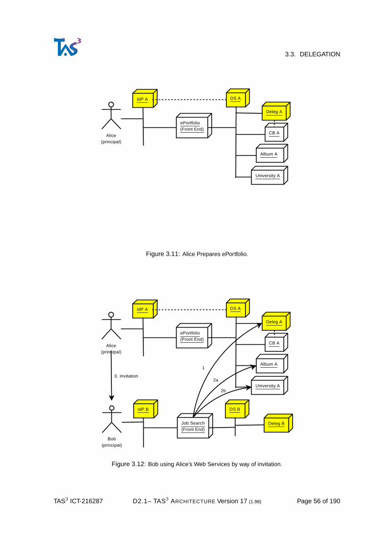
3.3. DELEGATION
Alice(principal)
IdP A
ePortfolio(Front End)
DS A
Deleg A
CB A
Album A
University A
Figure 3.11: Alice Prepares ePortfolio.
Alice(principal)
IdP A
ePortfolio(Front End)
DS A
Deleg A
CB A
Album A
University A
Bob(principal)
IdP B
Job Search(Front End)
DS B
Deleg B
1
2a0. Invitation
2b
Figure 3.12: Bob using Alice’s Web Services by way of invitation.
TAS3 ICT-216287 D2.1– TAS3 ARCHITECTURE Version 17 (1.98) Page 56 of 190

3.3. DELEGATION
3.3.1.1 Details of the Invitation Flow1151
Consider Figs 3.13 and 3.14 and the depicted steps as follows:1152
Service Provider
IDP_B
Delegation Service
Web GUI
PDP
1
Web Application
PID1 E(765)SPPID1 E(321)DSPID1 E(789)IM_B
PEP
Policy of SP
PII
Bob, Delegator
Invitation DB
Resource SecretURL PID in DS PID in SPArtefact
"Bob's R" sdfah.html 321 E(123)SPArtefact
Resource SecretURL PID in DS PID in SPArtefact"Bob's R" sdfah.html 321
SSO
2
1a1b
PDP
Delegtion Policy
"Bob's R"Bob's Resource
SSO
2a
2b3
Invitationsdfah.html
Alice, Delegatee
Invitationsdfah.html
3a
765SPSP
E(789)IM_Buse only: SP
8 times
IM_B
Figure 3.13: Invitation phase
1. Delegator (Bob) selects the resource to share at the Service Provider. Service Provider knows who1153
Delegator is as Bob used Single Sign-On to login to the SP.1154
2. Once a resource has been selected, Delegator is transferred to the user interface of the Delegation1155
Service. The Delegation Service generates an Invitation Ticket, which is formatted as URL pointing1156
back to the Web GUI of the Delegation Service, but with a nonce component that is hard to guess.1157
The invitation is remembered in the database of the Delegation Service.1158
TAS3 ICT-216287 D2.1– TAS3 ARCHITECTURE Version 17 (1.98) Page 57 of 190

3.3. DELEGATION
3. The Delegator then gives the invitation to Delegatee. The Delegator does not need to know the1159
specific identity of the Delegatee in the network. However, if the Delegator cares, he could use out1160
of band means of ascertaining that the Delegatee that receives the invitation is the person to whom1161
he wishes to delegate, e.g. instead of emailing the invitation, deliver it personally.1162
4. The Delegatee now resolves the invitation by clicking the URL and lands at the Web GUI of the1163
Delegation Service, which asks the Delegatee to identify itself by means of an IdP (usually Single1164
Sign-On). This IdP can be different from Delegator’s IdP as long as the Delegation Service and1165
the SP are willing to trust it. Various mechanisms, that are described in Sections 3.7 and 3.6, to1166
establish the trust exist.1167
If Delegatee does not have any IdP, then Delegatee should register with some IdP, otherwise he1168
can not continue the flow.1169
N.B. A flow is possible where the invitation itself grants access to the resource without1170
any need to authenticate the delegatee. While this flow may be interesting in some com-1171
mercial settings, it lacks sufficient audit and accountability safe guards to be included in1172
the TAS3 architecture.1173
5. Delegation Service invokes Delegatee’s Identity Mapping Service to convert the identity of the del-1174
egatee are the Delegation Service to the identity of the Delegatee at the SP and stores it in the1175
invitation database. The identity will be encrypted so that only SP can open it.1176
6. The Delegation Service generates an artifact with nonce properties and associates it with the in-1177
vitation. It then redirects the Delegatee to the user interface of the SP, passing the artifact in the1178
query string.1179
7. SP dereferences the artifact by contacting on back channel the Delegation Service, which looks up1180
the invitation using the artifact and generates a Delegation Token binding together the authorized1181
resource (known from time when invitation was created) and the Delegatee (known from step 5);1182
signs the token, and ships it to the SP.1183
8. The SP PEP now passes the invoking identity, i.e. the Delegatee, known from Single Sign-On1184
and the (contents of) Delegation Token to the PDP, which will authorize the operation. Typically1185
the authorization rule will require that the accessed resource and invocation identity match the1186
Delegation Token.1187
In this flow, the Delegation Service and the SP could be merged, effectively optimizing steps 2 and1188
7 to function calls. While such merge is technically sound, it may hinder development of competitive1189
market for the delegated services. The flows in [TAS3D42Repo] Appendix 2 "Proof of Ownership1190
Using Permanent IDs" essentially presents the invitation flow where the invitation is then embedded in1191
a composite document. That Appendix does not show how the Proof of Ownership URL (PoOURL) is1192
dereferenced. Essentially the steps 4-8 could be performed, or other means to authorize the access1193
could be used. It is important to understand that reliance on mere invitation does not leave audit trail1194
trace about who accessed. The delegatee really needs to be identified (e.g. by SSO to Delegation1195
Service) for the audit trail to be useful.1196
Essentially the steps 4-8, above, could be performed, or other means to authorize the access could1197
be used. It is important to understand that reliance on mere invitation tokens (secret URLs) does not1198
provide identity information to the audit trail about who accessed the document. But if authentication1199
TAS3 ICT-216287 D2.1– TAS3 ARCHITECTURE Version 17 (1.98) Page 58 of 190

3.3. DELEGATION
Service Provider
IDP_A
Delegation Service
Web GUI
PDP Web Application
PID2 E(123)SPPID2 E(769)IM_APID2 E(457)DS
PEP
Policy of SP
PII
Invitation DB
Resource SecretURL PID in DS PID in SPArtefact
"Bob's R" sdfah.html 321 E(123)SPArtefact
Resource SecretURL PID in DS PID in SPArtefact"Bob's R" sdfah.html 321 E(123)SPArt_1
2
PDP
Delegtion Policy
"Bob's R"Bob's Resource
Invitationsdfah.html
Alice, Delegatee
4
4a
4b
457DSDS
E(769)IM_Ause only: SP
8 times
IM_A
ID MAPPER A
E(769)IM_Ause only: SP
8 times
IM_A
5a
123SPSP
5b
769 E(123)SP769 E(457)DS
6
Art_1
6a6bE(769)IM_Ause only: SP
8 times
IM_A123SP
SP
Art_1
7a
Delegation TokenResource: "Bob's R"Delegatee: E(123)
7b
8
Bob's Resource
Figure 3.14: Accept invitation phase
and authorisation of the PII recipient took place because a fixed proof public URL was used, then full1200
audit information is provided.1201
TAS3 ICT-216287 D2.1– TAS3 ARCHITECTURE Version 17 (1.98) Page 59 of 190
3.3. DELEGATION
3.3.1.2 Reuse of Invitation1202
One salient property of this flow is that the first time the invitation is dereferenced, it gets bound to a1203
concrete user. In subsequent attempts to dereference the invitation a check can be made that it is the1204
same user (but if requirement really is that the token should be reusable by different users, then this1205
check can be omitted).1206
3.3.1.3 Application of Invitation Approach to Back Channel Web Service Calls1207
The invitations approach can be extended to cover back channel web service calls as well. This topic1208
will be elaborated in the next version of this deliverable (D2.1 M30).1209
3.3.2 Mandate Tokens Approach1210
This approach is described in [Peeters09].1211
Next version of this deliverable (D2.1 M30) will outline application of Mandate Tokens to TAS3 archi-1212
tecture, including1213
• Emission1214
• Push Model1215
• Pull Model1216
3.3.3 Delegation by Direct Authorization Rule1217
In this model the resource owner, knowing delegatee’s full identification, creates an access control rule1218
at the resource, i.e. sticky policy, that simply authorizes the delegatee to access the resource.1219
The ability to assign access to other user can be regulated by policies that are checked by the sticky1220
policy interface, e.g. by consulting a PDP.1221
When delegatee accesses the resource, he identifies himself using the usual token passing flow,1222
see Section 3.2, and the PDP is able to match his identity to the sticky policy authorizing the access.1223
Difficulties are1224
1. The Delegator has to have a solid identifier for the delegatee. This may be difficult for a human to1225
know and accurately enter. It is possible to offer to the delegator a browsing or search interface1226
of all potential delegatees, but such list may be unacceptable from data protection perspective and1227
can be difficult to implement in a distributed way.1228
A better alternative may be to adopt the invitation steps 1-4 from section 3.3.1 and modify the step1229
4 so that it edits the access control rule.1230
2. The resource has to have a sticky policy editing interface and access to this interface needs to be1231
well controlled. Online editing of policies increases exposure and potential for compromise.1232
3. If policy editing interface is centralized (e.g. in Dashboard), the identification of the resource to1233
which the policy applies may be difficult. This can be solved to an extent by Discovery. The the1234
policy editing interface of the resource would have to be web service based, with proof of presence1235
of the delegator.1236
TAS3 ICT-216287 D2.1– TAS3 ARCHITECTURE Version 17 (1.98) Page 60 of 190

3.3. DELEGATION
4. Privacy is poor as the requirement to know delegatee’s identity widely excludes pseudonymous1237
approaches.1238
5. Invitations are not supported1239
3.3.4 Delegation by Role Based Authorization Rule1240
In this model the resource owner creates an access control rule at the resource, i.e. sticky policy, that1241
authorizes anyone having a given role to access the resource.1242
The ability to assign access to a role can be regulated by policies that are checked by the sticky1243
policy interface, e.g. by consulting a PDP.1244
The assignment of a role to a delegatee is performed by some role authority outside control (but still1245
accountable through TAS3 oversight) of the resource owner. The usually role assignment is performed1246
using a special Sharing GUI that the role authority accesses (his authorativness is checked by separate1247
access control policy verifying that he is a role authority). The role authority needs to identify the1248
delegatee and then assign the role.1249
The role is stored in delegatee’s role repository, which can be his Attribute Provider.1250
When delegatee accesses the resource, he identifies himself using the usual token passing flow,1251
see Section 3.2, and the PDP is able to retrieve his role and match that to the sticky policy authorizing1252
the access. The role retrieval may be through push or pull model.1253
In its basic form the RBAC allows any role holder access to any resource that accepts the role and1254
the identity of the role holder is irrelevant, thus permitting use of pseudonyms or transient identifiers1255
that improve the privacy.1256
However the fact that the resource is not constrained is a problem. This could be solved by having1257
as many roles as there are resources, but this would lead to combinatorial explosion in the number of1258
roles and quickly become unworkable. Also, the role identifier itself could become a correlation handle1259
across the resources of a user.1260
A way to constrain the role is to parametrize it. Parametrized roles have a main part that specifies the1261
role proper and then a parameter that specifies to which resource the role applies. Since parametrized1262
role identifier has unique identifier properties, it is highly liable to become a correlation handle.1263
This approach adds flexibility, but still suffers from need to have exposed policy editing interface and1264
to some degree about the problem of identifying the delegatee and resource. In parametrized variant1265
any privacy protection is quickly lost.1266
3.3.5 Token Based Delegation to Well Known Delegatee1267
If Delegatee’s accurate identification can be known, the delegator can instruct a Delegation Service to1268
create a signed (by Delegation Service) token for accessing his resource. The fact that he can make1269
this delegation is checked against issuing policies, such as "data owner can delegate access to it".1270
The token can then be stored for future use in several places:1271
1. In Attribute Authority of the Resource Owner1272
2. In Attribute Provider of the Delegatee1273
3. In token store of the Delegation Service1274
TAS3 ICT-216287 D2.1– TAS3 ARCHITECTURE Version 17 (1.98) Page 61 of 190

3.4. SUBJECT OF THE PII NOT PRESENT -TRANSACTION
When Delegatee accesses the resource, he can push the token, obtained from (2) or (3), to the web1275
service that provides the resource. The token will identify the resource to which it applies, this is the1276
Target Identity.1277
Sometimes the mere presence of the delegation token is sufficient for accessing the resource, this1278
would be considered a bearer token.1279
However, in a more common case, the Delegatee also pushes a token identifying himself, e.g. a SSO1280
token. This expresses the Subject Identity, i.e. the identity of the user performing the access. This1281
allows the delegation token to be constrained to a user who can present token evidence of actually1282
being the Delegatee. This is essentially a Holder-of-Key proof and produces strong audit trail that1283
identifies who delegated and to whom.1284
Another variant is for the resource providing the web service to pull the delegation token from one1285
of the sources. If Subject Identity is not known, but the accessed resource is known, then (1) can be1286
used. In effect the discover of the Attribute Authority is keyed on the identity of the resource owner.1287
Token can also be retrieved from (3). Finally, if the Subject Identity is known, pulling the token from (2)1288
becomes possible.1289
3.3.6 Token Based Delegation of a Received Role1290
If a user has a role, given to it by some role authority, and policy permits delegation of this role, the1291
user can go to the Sharing GUI and ask a delegation token to be issued with known delegatee and1292
known target resource. Accurately identifying the delegatee and the target are serious problems as1293
described above.1294
The ability to delegate only "received role" is expressed by Delegation Service having a policy which1295
states that delegator can only delegate roles he has himself, as determined by the roles the authority1296
has assigned to the user.1297
The issued token is then stored for use by method (2) or (3) as discussed earlier. The token can be1298
used for access either by push or pull methods.1299
3.3.7 Multi-layer (Chained) Delegation1300
The token based delegation methods described above lend themselves to multi-layer delegation. In1301
this case the delegation is with right to sub-delegate and the delegatee is able to request that further1302
delegation tokens are created, or that an invitation is created.1303
For access authorization generally only the last step of a delegation chain is important, but for audit1304
purposes the full chain is needed.1305
The flows and tokens associated with multi-layer delegation are a topic of research in the TAS31306
project and will be further elaborated in a future version of this deliverable (D2.1 M30).1307
3.4 Subject of the PII Not Present -Transaction1308
There are two main categories for supporting PII-Subject-Not-Present transactions1309
1. PII Subject consented at some earlier time.1310
If the consent was expressed by the PII Subject by creating a policy that authorizes the delegation,1311
then we need to establish from the audit trail that only the user could have created the policy.1312
TAS3 ICT-216287 D2.1– TAS3 ARCHITECTURE Version 17 (1.98) Page 62 of 190

3.5. BREAK-THE-GLASS AUTHORIZATION
If token based delegation is used, PII-Subject-Not-Present could be implemented by "cacheing" an1313
access credential for long time. Due to obvious problems with long term valid access credential,1314
we only allow cacheing the discovery bootstrap credential. Using this credential the WSC MUST1315
request a fresh access credential for the PII-Subject-Not-Present transaction immediately before1316
attempting the transaction. This ensures that the PII Subject has control and visibility since the1317
Discovery will be a third party to the transaction, allowing additional audit correlation. Discovery1318
can also be used as centralized revocation point for the consent to the off-line transaction up to the1319
point when the transaction is actually made.1320
The discovery token was originally issued for a purpose and when a transaction token is requested,1321
including the PII-Subject-Not-Present situation, a purpose MUST be declared so that the authoriza-1322
tion process at the discovery can make appropriate decisions.1323
2. Transaction is permitted by law or contract without consent of the PII Subject. In this case the big1324
problem is that as the PII Subject might never have been present we need to consider how the1325
Legitimate Initiator (LI) identifies the PII Subject in the first place.1326
a. The PII Subject has a federated account at the Legitimate Initiator. In this case the LI can ask1327
the IdP to issue a discovery token. Such issuance needs to be strictly controlled. The LI is first1328
authenticated (e.g. using PKI at TLS level) and then LI presents the legitimate purpose why the1329
token is sought. The IdP will consult a PDP which will make the policy decision whether under1330
these circumstances the discovery token should be issued. The audit trail shall rigorously reflect1331
these events. After the discovery token has been obtained, the rest of the steps are as in (1).1332
b. The PII Subject has an account at the Legitimate Initiator, but it is not federated. The issuance1333
step of (a) will have additional request to create the federation. If the PII Subject eventually ends1334
up using the LI through SSO, the already created federation will be used.1335
c. The PII Subject does not have an account anywhere. In this case a stand-in account needs to1336
be created first and then the process of (b) and (a) will be followed. If the PII Subject eventually1337
starts using the LI using SSO, a problem remains on how to associate the PII Subject to the1338
already existing account. This may be possible by asking some identifying information, such as1339
sector specific or national identifier upon first SSO use. If asking such information is infeasible, or1340
the PII Subject can supply wrong information, we may well end up with user having two accounts1341
at the LI. Depending on the circumstances, this may not be a problem, or an administrative1342
procedure may be needed to combine the accounts.1343
3.5 Break-the-Glass Authorization1344
This section addresses Reqs. D1.2-3.9-BPRecover, D1.2-4.6-BrkGlass, and D1.2-7.22-BrkGlass. See1345
[TAS3D71IdMAnAz] for further discussion of the Break-the-Glass authorization.1346
In a Break-the-Glass scenario an operation would not normally be authorized given the actor and1347
the resource (including owner of the resource), but given justified and legitimate imperative need, the1348
operation is authorized, usually with additional auditing enabled.1349
A classical example would be an unconscious patient brought to an emergency ward. The physician1350
has imperative need to access the patient records, yet the patient can not consent to the access.1351
The Break-the-Glass authorization is an area of active current (2009) research and TAS3 architec-1352
ture will in its future versions incorporate the best innovations in this area. Our current approach is as1353
follows1354
TAS3 ICT-216287 D2.1– TAS3 ARCHITECTURE Version 17 (1.98) Page 63 of 190

3.6. TRUST AND PRIVACY NEGOTIATION
PEP driven Break-the-Glass (RECOMMENDED approach): The PEP attempts authorization which1355
fails for normal access. At this point PEP determines if Break-the-Glass could be applicable (could be1356
indicated by PDP or structurally known by the PEP). If so, the PEP may proceed to ask consent from1357
the actor ("Do you want to invoke Break-the-Glass privileges and additional auditing?") using interac-1358
tion facilities of the architecture, or in some cases may enable the Break-the-Glass automatically.1359
Enabling Break-the-Glass forces additional audit messages to be generated at the PEP and by the1360
service overall. It is also possible that the Break-the-Glass authorization is explicitly asked from the1361
PDP in which case there will be audit entry also on the PDP side, permitting better cross correlation of1362
the audit trails.1363
Policy editing driven Break-the-Glass : In this approach, after initial denial of the authorization,1364
some mechanism is invoked to modify the policy such that the same actor will succeed in obtain-1365
ing authorization. This approach is NOT RECOMMENDED due to complex security implications of1366
allowing policy editing.1367
Role driven Break-the-Glass : This is similar to the Policy Editing approach, but the edit happens in1368
the role authority. This approach is NOT RECOMMENDED for much the same reasons as Policy Edit-1369
ing: the role authority needs to be strictly controlled and introducing automated role editing mechanism1370
is not desirable.1371
Delegation driven Break-the-Glass : In this approach after the failure, the actor visits the dele-1372
gation authority and claims Break-the-Glass situation. The delegation authority verifies according to1373
its policies if the Break-the-Glass delegation is appropriate given the actors role, etc., the resource,1374
and the context of the request. If acceptable, the Delegation Authority issues a delegation token with1375
special field that indicates the Break-the-Glass nature of the delegation and records the fact to its audit1376
trail. When the delegation token is wielded at the PEP, it recognizes the delegation authority as trust-1377
worthy and notices the Break-the-Glass indication, enabling more extensive logging. This approach1378
can be made to work.1379
External Break-the-Glass IdP driven approach : This approach is a front channel special case of1380
the PEP driven approach with some features of the Delegation driven approach. The particularity is1381
that the PEP redirects the user, with indication of the resource to be accessed, to a special IdP which1382
is responsible for verifying (probably querying a PDP) whether the user is eligible for Break-the-Glass1383
access. If so, it issues a token indicating that the user is eligible and has been granted access, what1384
resource is to be accessed, and the fact that Break-the-Glass has been invoked. The PEP seeing this1385
token grants access, but enables additional logging. The special IdP will also have audit trail of the1386
events, so it will be possible to cross check the trails.1387
3.6 Trust and Privacy Negotiation1388
This section addresses Req. D1.2-7.17-Increm.1389
Trust and Privacy Negotiation logistics and flows are subject to TAS3 research. A future version of1390
this deliverable (D2.1 M30) will report on these mechanisms in detail.1391
To give rough overview, the Trust and Privacy Negotiation can be carried at two levels: on Front1392
Channel a user interface (Web GUI of a Front End) will step user through sequence of mutually re-1393
vealing more information until agreement can be reached and transaction can be completed. This may1394
involve the user agreeing to relax policies on his data, or the Service Provider agreeing to honour some1395
additional user policy that it did not offer originally. The second level is Trust and Privacy Negotiation1396
in the back channel. The Discovery Service plays a large role in the Trust and Privacy Negotiation at1397
TAS3 ICT-216287 D2.1– TAS3 ARCHITECTURE Version 17 (1.98) Page 64 of 190

3.7. INTEROPERATION ACROSS TRUST NETWORKS
this level. The mechanics are further described in [TAS3D41ID].1398
3.7 Interoperation Across Trust Networks1399
General approach for interoperation across Trust Networks is described in [LibertyInterFed], which1400
focuses on the token passing flows in inter-federation situation. In addition to token passing, interop-1401
erability at data level is needed, i.e. the ontologies in use in the different Trust Networks either need to1402
be the same or they need to be mapped. In particular, authorization critical data needs to be mapped.1403
Next version of this deliverable (D2.1 M30) will provide specifics of interoparation, based on TAS31404
research and implementation experience.1405
3.7.1 Semantic Interoperability Engine1406
This section satisfied Reqs. D1.2-2.23-SemIOP, D1.2-3.14-PIIPolicyDisco, and D1.2-3.15-SecPreserve.1407
Audit & Monitor
Modelling (conceptual level)
Org BOrg A(Context A) (Context B)
Runtime
Audit & Monitor
Runtime
Ontology A Ontology B
Modelling (conceptual level)
Semantic Inter-operability Engine
ServiceRequester
ServiceResponderAz AzTransformer
Existing Transforms
Figure 3.15: Interoperation across contexts.
A semantic interoperability provides different mechanisms to map ontological entities from hetero-1408
geneous entities. Castano et al. [Castano07] identify two main categories of ontology matching tech-1409
niques; namely linguistic and contextual matching techniques. Linguistic techniques evaluate the sim-1410
ilarity among ontological content (i.e. classes, roles and instances) based on their names or labels.1411
The main characteristic of these techniques is that they evaluate the similarity between two strings1412
of characters. For example, the edit distance counts the minimum number of changes, such as in-1413
sertion, deletion and replacement of characters, required to transform one string into the other string1414
[Levenshtein66]. Although linguistic techniques often provide highly precise mappings, these tech-1415
niques tend to fail when there is little lexical overlap between the labels of ontological entities. Contex-1416
TAS3 ICT-216287 D2.1– TAS3 ARCHITECTURE Version 17 (1.98) Page 65 of 190

3.8. PROPERTIES OF WEB SERVICE BINDING
tual matching techniques can remedy this problem by assuming that some of the meaning of an entity1417
is conveyed by its context. For example, Dieng and Hug [Dieng98] calculate the similarity between1418
two concepts based on their direct super-classes and/or direct subclasses and/or sibling classes. The1419
semantic interoperability engine will include different algorithm of these types, and thus be able to deal1420
with a wide range of mismatches. As a result, multiple organisations using different conceptualisation1421
will be able to interoperate to achieve a common goal.1422
As shown in Fig-3.15, the Semantic Interoperability Engine (SIE) works at conceptual level. It can1423
be used process the two ontologies to produce Transforms that may be stored for later use. SIE can1424
run as a scheduled batch to update the transforms, or change in either ontology can be used to trigger1425
SIE. Finally it may be possible to invoke SIE dynamically whenever an existing transform is not yet1426
available.1427
At runtime an efficient Transformer uses the Transforms to translate data in the messages that are1428
exchanged. TAS3 focus is on using this mechanism to transform security, trust, and privacy related1429
attributes such as roles. However, the mechanism in itself could be used for payload data transfor-1430
mation as well. The transform can be done in sending or receiving end. The Transformed has to be1431
positioned such that each PEP (which calls PDP, passing the attributes along) will have the security1432
related attributes in its own vocabulary. In the sending end this means after authorization, in receiving1433
end before authorization.1434
3.8 Properties of Web Service Binding1435
Web Service Binding is a set of features that the communications layer is assumed to have. These1436
features are often required by more sophisticated protection mechanisms like the tocken passing flows.1437
They often address basic and well known threats like replay, unauthorized, and man-in-the middle1438
attacks in basic way while other mechanisms may address the same topics comprehensively, but in a1439
more expensive way. Many of these features may seem selfevident, but we need to list them even if1440
just to state the obvious.1441
1. Mutual authentication of the communicating entities MUST be possible. Usually this is done using1442
transport layer digital certificates, but other approaches are possible.1443
2. Link confidentiality MUST be possible, usually using transport layer encryption.1444
3. Correlation1445
- Request-Response Correlation1446
- Business Process identification in correlation1447
4. Redirection support for flexibility1448
5. Recredentialing support (Req. D1.2-3.9-BPRecover )1449
6. Asynchronous support SHOULD be implemented (this will be addressed in a future version of this1450
document)1451
7. Interaction Callback (or Exception Request)1452
- Interaction Redirect (Req. D1.2-3.9-BPRecover )1453
TAS3 ICT-216287 D2.1– TAS3 ARCHITECTURE Version 17 (1.98) Page 66 of 190

3.8. PROPERTIES OF WEB SERVICE BINDING
- Interaction Service (Req. D1.2-3.9-BPRecover )1454
8. Digital signing of messages for nonrepudiation (Reqs. D1.2-2.11-Transp, D1.2-2.15-Resp, D1.2-1455
4.4-CourtProof )1456
TAS3 ICT-216287 D2.1– TAS3 ARCHITECTURE Version 17 (1.98) Page 67 of 190

1457
4 Application Specific Architecture1458
4.1 Protocol Support for Conveyance of Sticky Policies1459
Most of the protocol flows of TAS3 use industry standard Web Services bindings and Web Services1460
payload protocols. It is an explicit design goal that existing services are enabled with minor disruption.1461
A pertinent problem with existing payload service protocols is how to express the sticky policies1462
that generally have to be bound to the data with a digital signature. Following approaches have been1463
identified1464
1. Treat all data in one request-response pair as having the same Sticky Policies. In this cases rel-1465
atively nonintrusive methods like SOAP headers and LDAP controls can be used to indicate the1466
sticky policies. We call this Security Header (SH) approach. This approach is already available as1467
UsageDIrective SOAP header defined in [IDWSF08].1468
2. Use the extension points of the payload protocol to express the Sticky Policies. We call this ap-1469
proach Application Protocol Enhancement (APE), see [TAS3D71IdMAnAz] section 8.2. This ap-1470
proach gives granular Sticky Policies that are naturally associated with the data and does not alter1471
top levels of protocol processing. If client and server are updated to understand this scheme then1472
it works well. Eventually new payload protocols should be specified with TAS3 APE feature built in.1473
A danger of this approach is that if the client is not updated, it may just silently ignore the Sticky1474
Policies.1475
3. Expand the data model to carry sticky policies. This is really a special case of APE with similar1476
merits and problems. One benefit is that it is sometimes easier to extend a datamodel than a1477
protocol.1478
4. Encapsulating Security Layer (ESL), see [TAS3D71IdMAnAz] section 8.2. Wrap the payload proto-1479
col in a TAS3 defined encapsulating protocol that contains all the TAS3 specifics and in particular1480
the sticky policies. Advantages of this approach include1481
• The encapsulated protocol does not need to be modified at all1482
• Possibility to add sticky policies to protocols that do not offer extension points and that are not1483
under control of the implementer.1484
Disadvantages of this approach are1485
• More invasive on outer layers of the protocol stack. This may make it difficult to integrate to1486
existing protocol stack.1487
• If the payload protocol is not SOAP, or otherwise has poor impedance match to the TAS3 ESL1488
protocol, then integration may be impossible.1489
• Association of the sticky policies to the data will require awkward correlation of data items to1490
the policies. In particular, if the data does not have item specific IDs, it may be necessary to1491
resort to use of techniques such as [XPATH99].1492
TAS3 ICT-216287 D2.1– TAS3 ARCHITECTURE Version 17 (1.98) Page 68 of 190

4.2. LEGACY INTEGRATION STRATEGY
Given the multiplicity of approaches, each with its merits, the problem arises as to which one should1493
be used. Luckily all can coexist in the same Trust Network. This is made possible by expressing1494
different approaches as different Service Types so that it is possible to discover services that make the1495
approach supported by the client possible. Another approach is to use autodetection, observing the1496
namespaces and elements passed in the SOAP payload to determine which one is being used.1497
Which of the approaches works best and difficulty of supporting several in parallel are topics of1498
active research in TAS3. A future version of this document will give better guidance for selection of the1499
approach. Currently (May 2009) the APE approach has been successfully used in situations where1500
payload protocol was under our control. The ESL approach has been prototyped, but the specifics of1501
this protocol are still to be determined.1502
4.2 Legacy Integration Strategy1503
For TAS3 architecture to be useful, it needs to be adopted. To adopt TAS3 an existing application faces1504
some implementation choices.1505
Service Responder
TAS3SOAP
Stack
Master PDP
XACML (in SOAP envelope)
Data ServiceWeb Service (e.g. Attribute Authority)
User
FE
PEP-In(accept req)
PEP-Out(filter)
Application with PEP built in
Figure 4.1: Application Integration: PEP implemented directly in application.
Conceptually simplest, but in terms of new code to write probably most costly approach is shown in1506
Fig-4.1: just build a TAS3 compliant PEP into the legacy application. This approach has the advantage1507
of allowing full control over the enforcement process, including the inputs to the Master PDP. The1508
disadvantage is the learning curve to learn TAS3 architecture in sufficient detail to implement it correctly1509
and to get certified.1510
Fig-4.2 depicts a slightly different strategy where application only implements a simple PEP, which1511
then communiates with the Application Indepentent PEP (AIPEP) supplied by the TAS3 Project. In1512
this approach, the AIPEP component handles most of the TAS3 specific parts and can be an already1513
certified component, making compliance certification easier.1514
However, in this model the need to communicate between AIPEP and ADPEP arises. The commu-1515
nication pattern could be either Encapsulating Security Layer (ESL) or Application Protocol Enhance-1516
ment (APE), as described in the Section ??1517
TAS3 ICT-216287 D2.1– TAS3 ARCHITECTURE Version 17 (1.98) Page 69 of 190

4.3. ADPEP
Service Responder
TAS3SOAP
Stack
Master PDP
XACML (in SOAP envelope)
Data ServiceWeb Service (e.g. Attribute Authority)
User
FE
AIPEP-In(accept req)
AIPEP-Out(filter)
AIPEP
Application
ADPEP
Figure 4.2: Application Integration: ADPEP implemented in application itself.
Fig-4.3 illustrates some specific integration strategies with the intent of enabling legacy data sources1518
that can not be modified. In (A) the SOA Gateway evolves to support TAS3 architecture, in (B) the SOA1519
GW is frontended by the WP9 database which supports the TAS3 architecture aspects. If export of the1520
legacy data is an option, then it may be simplest to import the data to WP9 database and dispense1521
with the legacy data source entirely (C).1522
Service Responder
TAS3SOAP
Stack
Master PDP
XACML (in SOAP envelope)
Data ServiceWeb Service (e.g. Attribute Authority)
User
FE
AIPEP-In(accept req)
AIPEP-Out(filter)
AIPEPApplicationDependentPEP
LegacyData Source
Data
A
B
C
WP9SOA Gateway
WP9SOA GW
WP9database
WP9database
Figure 4.3: Application Integration using ADPEP and (A) SOA Gateway, (B) WP9 DB as frontend to SOA GW,(C) WP9 database.
TAS3 ICT-216287 D2.1– TAS3 ARCHITECTURE Version 17 (1.98) Page 70 of 190
4.3. ADPEP
4.3 ADPEP1523
The Application Dependent Policy Enforcement Point (ADPEP) is a gateway that provides access to1524
the TAS3 infrastructure for applications like web applications with a web frontend, business process1525
engines, databases or repositories and many other systems, which are either requesting or responding1526
over a TAS3 secured and trusted channel. Per section 2.2.1 (see also Fig-2.2), the ADPEP belongs to1527
the Front End Services and Web Service components inside the Payload boundary.1528
As described in Section 2.2.2, the ADPEP is divided into two different types of Application Dependent1529
Policy Enforcement Points:1530
1. ServiceRequester ADPEP: This web service is part of the Front End Services. Internally, the Ser-1531
viceRequester ADPEP constitutes together with the Stack, the Service Requester. The Stack han-1532
dles SOAP protocol details. The Application Independent Policy Enforcement Point (AIPEP) con-1533
tacts Master PDP, which contacts different PDPs like User PDP, Organization PDP or a Trust PDP1534
to decide whether a requested is trusted or not.1535
The main task of the ServiceRequester ADPEP is to collect all required information for an appro-1536
priate request that has to be checked by the TAS3 authorization infrastructure. Further informa-1537
tion about the payload, which builds up the request, can be found in [TAS3D81RepoSW] figure1538
8. Common information about the functionalities of the ServiceRequester ADPEP can be found in1539
[TAS3D81RepoSW] and in [TAS3D83CliSW].1540
The next steps before sending the request are done by the ’Stack’. As mentioned before, the ’Stack’1541
(and its main component: the AIPEP) is application independent. Its main task is the preparation1542
of the request. The message has to be signed and augmented according to web services binding.1543
WP4, WP5 and especially WP7 work on this security related part of the service requester. Whereas1544
WP8 is responsible for the application dependent part.1545
2. ServiceResponder ADPEP: This second application dependent service, which functions as respon-1546
der, is part of the Service Responder component in the Web Service boundary (see Fig-2.3). In1547
analogy to the ServiceRequester ADPEP, the ServiceResponder ADPEP also needs the ’Stack’1548
(with AIPEP and its underlying PDPs) to function correctly. That means, signing and preparation of1549
the message according to the web service binding, the policy checks and the communication with1550
the ’Trust policy decision point’, as done by the ’Stack components’.1551
The main task of the ServiceResponder ADPEP is to receive requests, route them in an appropriate1552
way to the ’Service Application’ and then send back the response to the requester. More details1553
about the functionalities of the ServiceResponder ADPEP can be found in [TAS3D81RepoSW] in1554
chapter 3.2.1555
Auxiliary components in the both ADPEP Services1556
To fulfil the mentioned functions of the both ADPEP Services (Requester and Responder), some1557
auxiliary services are required. These services belong to tasks (Task 8.3 - see DoW), which are1558
documented in [TAS3D82BackOffice].1559
These services neither store person related data nor serve the user directly. They provide ontologies1560
and metadata, perform search and aggregation operations and transform data into specific formats.1561
The back office services are a component of the TAS3 Trusted Application Infrastructure but not of the1562
core TAS3 Trust and Security Infrastructure.1563
The main Auxiliary or Back Office Services and Components are:1564
TAS3 ICT-216287 D2.1– TAS3 ARCHITECTURE Version 17 (1.98) Page 71 of 190

4.3. ADPEP
• The Generic Data Format ([TAS3D82BackOffice], section 2.1.2) used to store data in TAS31565
repositories11566
• Services to transform ([TAS3D82BackOffice], section 2.1) data from a custom source format to1567
the Generic Data Format and from the Generic Data Format to a format, which is requested1568
(and supported).1569
• Aggregation Service ([TAS3D82BackOffice], section 2.2) and Policy Aggregation ([TAS3D82BackOffice],1570
chapter 8)1571
• Request Logger Service ([TAS3D82BackOffice], section 3.2) to store information on requests1572
issued and responses received by TAS3 web services for auditing and maintenance purposes1573
1Marc: not applicable for eHealth because of legal issues.
TAS3 ICT-216287 D2.1– TAS3 ARCHITECTURE Version 17 (1.98) Page 72 of 190

1574
5 Using Business Process Modelling to Configure the1575
Components1576
This section addresses Reqs. D1.2-3.2-ModelDrivenCfg, D1.2-3.12-SPManifest, D1.2-6.3-WhatHowWhyWho,1577
and D1.2-6.4-Min.1578
The TAS3 architecture covers a lot of functionality and some of this functionality needs to be config-1579
ured carefully to match each other to ensure smooth operation from the perspective of the users, such1580
smooth operation is perceived by users as dependability and trustworthiness, so it is a prerequisite for1581
good public image of a Trust Network.1582
Correct configuration will also be essential for ensuring that services function securely. Given that1583
most security technology is quite brittle and even minute misconfigurations lead to failure, there will1584
be operational and commercial pressure to turn off those nonfunctional, but essential features that1585
appear to be "causing trouble". This is an extremely dangerous slippery slope that any Trust Network1586
MUST avoid. Liberty Alliance and SAML Interoperability and Certification programmes have clearly1587
demonstrated this to be a real peril. Therefore it is necessary that it is possible to correctly configure1588
the trust network such that it will work right on the first try.1589
Complexity of a typical Trust Network, along with all of its member systems, is of such a high degree1590
that it is infeasible to configure it sufficiently correctly by a manual approach. Humans make mistakes.1591
An automated, model driven configuration is the only way to create accurate and correct configuration.1592
The corner stone is Business Process Modelling. From this model, which exists both at the top Trust1593
Network level and at the organizational level, it should be possible to derive the following outputs:1594
1. Circle of Trust parameters to facilitate federation and SSO configuration1595
a. White list of roots of trust for both authentication and authorization1596
b. Trusted Certificates for TLS [RFC3548] and Signing1597
c. Metadata for entities1598
2. Declarative Statements about attribute needs of the Clients as well as policies under which providers1599
are willing to release attributes. This output will come in the form of [CARML] and [AAPML] files,1600
see further [IGF], that can be used to automatically configure IGF enabled layers of Client Request1601
PEP and Provider Request PEP.1602
3. Some of the top level policies that apply to the Trust Network and its members. This should facilitate1603
configuration of the PDPs.1604
4. Policies, Business Process Models, and Interface Descriptions (e.g. WSDL) that are needed as1605
input for the Automated Compliance Validation.1606
5. Business Process Models that are needed as input for Business Process Visualization at the Dash-1607
board.1608
6. Policy and business process model descriptions needed by the Configuration and IT infrastructure1609
management, e.g. CMDB, ITIL, etc.1610
TAS3 ICT-216287 D2.1– TAS3 ARCHITECTURE Version 17 (1.98) Page 73 of 190

Contractual information behind a business process will influence the business process model itself1611
and has an impact on the security rules, roles, and policies related to the business process.1612
Security rules that guide selection of web services and use of secure entities (data), i.e. influence1613
the discovery service.1614
Security exceptions during business processes will raise an exception. Unhandled exceptions will1615
block or break the process (go to an operator or help desk). The challenge is to handle the exceptions1616
by explicit routines in the business process modelled routines or in some cases by using alternative1617
paths (i.e. subprocesses) to allow the process to complete or even to look ahead and avoid exceptions1618
before they occur by such means.1619
Business processes can have more complex topology than just trees.1620
There is no centralized log, just references to local logs are passed out.1621
TAS3 ICT-216287 D2.1– TAS3 ARCHITECTURE Version 17 (1.98) Page 74 of 190

1622
6 Oversight and Monitoring1623
For a TAS3 compliant Trust Network to gain a trustworthy reputation and to ensure that belonging1624
to the Trust Network really enables lower cost of operation through lesser fraud, improved trust, and1625
ultimately less need for formal audits, it must take proactive and mandatory activities to monitor its1626
activities and stop any fraudulent practises before they become a problem, ideally even before they1627
become publicly known.1628
This section addresses Reqs. D1.2-2.11-Transp, D1.2-2.12-Compr, D1.2-2.15-Resp, D1.2-2.16-1629
Mitigate, D1.2-2.17-AuditUntamp, D1.2-2.21-DataProtLaw, D1.2-2.22-GovtAccess, D1.2-12.13-Vfy,1630
and D1.2-12.15-Valid.1631
In TAS3, the monitoring should happen at levels of1632
1. Continued automated, robotic, testing that compares results to both modelled expectations and1633
past results. This is one of the focus areas of TAS3. See: On-line Compliance Testing (OCT).1634
2. Operations monitoring to determine upness and performance of services, as well as detection1635
of anomalies. Trouble ticket system for reporting and rectification of operational errors, as well1636
as intrusion detection scans and monitoring are included here as well. Use of industry standard1637
solutions is recommended as TAS3 does not plan additional research in this area.1638
3. Log audit. Some part of log audit is handled in operations monitoring, above, but logs will contain1639
a wealth of additional information, such as usage patterns to inform new investment and areas1640
of innovation, which can be extracted using data mining techniques. Use of industry standard1641
solutions is encouraged in general as the only connection with TAS3 research is in the area of1642
gathering inputs for reputation scoring.1643
4. Formal compliance audits should occasionally be carried out manually to ensure that the automated1644
monitoring and audit mechanisms, above, are functioning correctly. These audits may be mandated1645
by legislation or by governance agreement and are typically fairly costly affairs with reputable out-1646
side consultants specializing in organizational and IT audits. TAS3 contribution for this area stems1647
from recommendations and guidelines of the project legal team.1648
5. Administrative Oversight. The Trust Guarantor will take necessary administrative steps to ensure1649
that the Trust Network is adequately monitored, mostly automatically, but with necessary and timely1650
manual intervention. The Trust Guarantor may, according to the Governance Agreement, be moni-1651
tored by an Advisory Board, Management Board, and ultimately General Assembly.1652
Section of 4.3.7 "Management" of [NexofRA09] discusses the need for management interfaces in1653
services components. TAS3 is compatible with these requirements.1654
6.1 On-line Compliance Testing1655
This section addresses Reqs. D1.2-6.14-Compat, D1.2-6.15-MinPolicy, and D1.2-12.16-OnlineTst.1656
Implementation of SOA based applications result from the integration of several services. Services1657
composing an application can change at run-time without informing all the other services integrated in1658
the application. Furthermore, features like dynamic binding, or context-dependency prevent knowing1659
before run-time the actual interaction among service instances.1660
TAS3 ICT-216287 D2.1– TAS3 ARCHITECTURE Version 17 (1.98) Page 75 of 190

6.1. ON-LINE COMPLIANCE TESTING
Speaking in general terms, services are typically controlled and owned by different organizations.1661
Thus, dealing with architectures that are not under the full control of one organization, means that1662
the service lifecycle cannot be structured in well-defined development stages. In particular, for a1663
(composite) service it is not clear when testing activities starts or should end.1664
To ensure trust and dependability the TAS3 architecture must also include adequate technology and1665
actors to test that services within a TAS3 Trust Network behave in compliance with their expected1666
specifications. Such testing activities must be performed on-line by special TAS3 guards, verifying that1667
the services with a choreography actually behave as expected.1668
To achieve trustworthy SOA, there is the need to develop and use a methodology and tools sup-1669
porting the "perpetual" (i.e. event-driven, periodically) and automatic testing of software services. The1670
benefits with the "perpetual" and automatic testing we envision:1671
• repeatability of testing (improving the efficiency and the efficacy of the test)1672
• increase the quality and the trust perceived by the users of the service1673
Deployment Compliance Validation Agency(contracted by Trust Guarantor)
Organization under test(optional, inthe future)
(optional, inthe future)
Model andInterface Policy
PlannerOCT
(schedule tests)
Policy TestRobot
Frontend GUITest Robot
Web ServiceTest Robot
ExpectedTest Results Past Real
Test Results
cmp
PDPundertest
FEundertest
WSundertest Report
Test, Test, Test Test, Test, Test
Figure 6.1: Overview of On-line Compliance Testing
The extent to which compliance is tested may vary, also depending on the registration information1674
that should accompany services (e.g. models describing interfaces, policies, usage, etc.), which is1675
part of the governance contract.1676
A minimal assumption is that services should access and perform within a TAS3 infrastructure ac-1677
cording to an explicitly declared set of policies and that the infrastructure should not allow violation to1678
the declared policy, or at least should recognize such violation. Testing is applied in order to reduce the1679
risk that services within a TAS3 infrastructure will get in contacts with unreliable services. Therefore1680
services within a TAS3 compliant infrastructure will be regularly submitted to testing session aiming to1681
assess that a service does not break its policy.1682
TAS3 ICT-216287 D2.1– TAS3 ARCHITECTURE Version 17 (1.98) Page 76 of 190

6.1. ON-LINE COMPLIANCE TESTING
As important remark, we advise that this on-line testing approach does not prevent the execution of1683
canonical off-line testing activities (e.g. where the service is tested by its developer trying to anticipate1684
possible usage scenarios), rather it is an additional mean to increase the trustworthiness of the TAS31685
architecture.1686
6.1.1 Involved Actors1687
On-line Compliance Testing impacts on the following of actors of the TAS3 scenario.1688
• Ecosystem1689
- Service Provider1690
- Reputation Providers1691
- Software Certification agencies1692
- Deployment certification and audit agencies1693
- Compliance Authority1694
• Components1695
- Web Service (WSP)1696
- IdP (Identity Provider)1697
- Service Registry1698
- Id Mapper1699
- Linking Service1700
- Organizational PDPs1701
- Trust Network PDP1702
6.1.2 On-line Testing Process and Architecture1703
The TAS3 architecture includes an on-line testing infrastructure, in which, the TAS3 services are tested1704
according to a set of published models describing specific behavioural characteristics of the service1705
itself. In the following, the term OCT refers both to the on-line compliance testing process and to the1706
infrastructure that implements it.1707
With respect to the current scope of the TAS3 architecture, the compliance testing functionality1708
requires that each service exposes within the TAS3 choreography its public interface (i.e. its exported1709
operations) and the public policies it will comply with (or a references to them). In particular, each1710
service is tested on-line when it requests to be registered to a TAS3 directory service. Further on-line1711
test sessions can be activated by the compliance testing (i.e. Trust Network level) directory service1712
either in event-driven or periodic fashion.1713
Directory Services within a TAS3 architecture interact with testing components to detect services1714
failures . The compliance testing increases trust both on the TAS3 architecture and the linked services.1715
A software service willing to be registered to a TAS3 directory service, may also have to comply with1716
other policies that are not publicly manifested. In this case the service will not be tested with respect1717
to such policies since such behaviour is hidden from the external interfaces of the service.1718
TAS3 ICT-216287 D2.1– TAS3 ARCHITECTURE Version 17 (1.98) Page 77 of 190
6.1. ON-LINE COMPLIANCE TESTING
During the on-line compliance testing process, references to the service should not be retrievable1719
by means of the directory service. At the end of the compliance verification process, if and only if all1720
the tests have been successfully executed, service references will be listed by the directory service.1721
During the on-line testing, the OCT activates tester robots. Each tester invokes the service under1722
test simulating service requests with identity credentials taken from a pre-packed identity test suite.1723
The tester robot collects the service reply (i.e. either a response message, or a deny access), and1724
compares it with the expected results: a difference between the service reply and the expected result1725
reveals a mismatch between how the service policy is manifested and how the policy is implemented1726
within the service.1727
Note that the TAS3 architecture has a precise requirement that error messages returned after a1728
request for a resource (e.g. "access denied" message) must be identifiable as such. Applications might1729
masquerade error messages for user-friendliness (e.g. they could produce a "pretty formatted" page);1730
nonetheless, the TAS3 architecture needs to be able to unambiguously recognize error messages1731
without the need to delve into the semantics of the payload of the message. This is accomplished by1732
each application declaring to the on-line compliance testing infrastructure at least one successful and1733
one failing test case with exact description of what the messages look like and what are the relevant1734
parts.1735
In real life scenarios, a service under test may need to access external services when invoked by the1736
tester robot. Indeed, in some cases a testing interaction between the service under test and externally1737
invoked service may have permanent effects (e.g. on a stateful resource). Let’s consider that the1738
service under test queries the directory service to lookup a relevant end point. In this case, OCT1739
should consider that the registry may return a reference to a Proxy version of the required service: this1740
service will implement the same interface as the required service. Doing so, the real implementation1741
of registered services is hidden to those services waiting for compliance validation - a useful feature1742
while project is ongoing and full service is yet unavailable.1743
In such cases, the directory service and OCT have to be able to link to an existing service proxy or1744
to generate new ones. Obviously this will increase the complexity of the framework and asks for the1745
provisioning of service description models suitable for automatic generation of service stubs.1746
Fig-6.2 depicts a UML Diagram describing the components of the On-line Compliance Testing frame-1747
work. In the following we list a detailed descriptions of each component:1748
• Compliance Validator Discovery Service: according to the architecture given in Fig-2.2, this com-1749
ponent enhances the functionality provided by the Discovery Service. In particular, the Compli-1750
ance Validator Discovery Service is a Discovery Service able to apply the compliance validation1751
at runtime. The Compliance Validator Discovery Service aggregates three sub-components: the1752
Compliance Validator, the Proxy Factory and the Pending Services DB.1753
• Compliance Validator : this component activates the testing session when a service makes a1754
request for being included in a TAS3 infrastructure. The testing session will result in a sequence1755
of invocations to the services requesting to be registered. In case the testing session does not1756
highlight any error the service will be registered otherwise the request will be rejected.1757
• Tester Robot: this is the component that actually runs the test on a given service. In particular,1758
the Compliance Validator activates the Tester Robot passing to it a reference to the service that1759
needs to be tested and to the corresponding test suites to use.1760
• Request Generator: this component defines which is the next invocation to make to the service1761
under test in order to assess its correctness;1762
TAS3 ICT-216287 D2.1– TAS3 ARCHITECTURE Version 17 (1.98) Page 78 of 190

6.1. ON-LINE COMPLIANCE TESTING
• Test Checker: this is the component that checks that the replies of the service under test actually1763
conform to what is specified;1764
• Test Attribute Generator: this component defines which attribute values are to be used in the1765
testing invocations.1766
• Front Channel Tester: this component extends the Tester Robot adding to the tester component1767
specific features to interact with the front channel of a service application in TAS3. Since this1768
component is a Tester Robot, it has all the features that a Tester Robot has, including the1769
relationship with the other components (e.g. Request Generator, Test Checker, Test Attribute1770
Generator).1771
• Back Channel Tester: this component extends the Tester Robot adding to the tester component1772
specific features to interact with the back channel of a service application in TAS3. Since this1773
component is a Tester Robot, it has all the features that a Tester Robot has, including the1774
relationship with the other components (e.g. Request Generator, Test Checker, Test Attribute1775
Generator).1776
• DB of Roles as Signed Test Response: this DB contains the identity test suite that the tester can1777
use to test other services simulating a different identity.1778
• DB Test Report: in this DB the compliance validator logs the result of a testing session and the1779
possible failures highlighted.1780
• Proxy Factory: this component automatically generates proxy services to simulate already reg-1781
istered services.1782
• Pending Services DB: this DB will contain the identities of services that requested to enter a1783
TAS3 infrastructure precinct but still did not pass the testing session. Services in such DB are1784
not returned as result of a discovery request. Identities are removed from this DB when the1785
corresponding testing session is terminated.1786
Note that, each entity (i.e. components or artifacts) in the diagram, has a role with respect to the1787
domain organization. Specifically, according to the general architecture depicted in Fig-2.2:1788
• The artifacts Public Interface, and Public Policy, are entities within the Modelling & Configura-1789
tion Management area,1790
• The OCT components (Compliance Validator Discovery Service, Compliance Validator, Tester1791
Robot, Request Generator, Test Checker, Test Attribute Generator, Front ChannelTester, Back1792
Channel Tester, DB of Roles, DB Test Report, Proxy Factory, and Pending Services DB) are1793
entities within the Audit & Monitor area,1794
• The components IDP, Discovery Service, and Web Service, are entities within the Runtime &1795
Enforcement area.1796
TAS3 ICT-216287 D2.1– TAS3 ARCHITECTURE Version 17 (1.98) Page 79 of 190

6.1. ON-LINE COMPLIANCE TESTING
ContinuedAutomaticComplianceValidationArchpackage Data[ ]
<<component>>
DB of Roles as Signed Test Response
<<component>>
Compliance ValidatorDiscovery Service
<<component>>
Pending Services DB
<<component>>
FrontChannel Tester
<<component>>
BackChannel Tester
<<component>>
CompliaceValidator
<<component>>
Request Generator
<<component>>
Test Checker
<<component>>
Discovery Service
<<component>>
Proxy Factory
<<component>>
Web Service
<<component>>
Test Attribute Generator
<<component>>
DB Test Report
<<component>>
IDP
<<component>>
Tester Robot
<<artifact>>
Public Interface
<<artifact>>
Public Policy
For example according to the SP-Initiated SSO with Redirect and POST Bindings schema at Fig.12 of the SAML Specification
Likely SAML Tokens
Test InvocationsRegistration Request
Extracted Form the Directory Service During Test Preparation
Extracted Form the idP During Test Preparation
<<manifest>>
<<manifest>>
<<use>>
<<use>>
Figure 6.2: UML Component Diagram of the On-line Compliance Testing (OCT).
TAS3 ICT-216287 D2.1– TAS3 ARCHITECTURE Version 17 (1.98) Page 80 of 190

6.2. OPERATIONS MONITORING AND INTRUSION DETECTION
6.2 Operations Monitoring and Intrusion Detection1797
[NexofRA09], section 4.3.7 "Management", paragraph 4, highlights the need for operational monitoring.1798
While such monitoring is not a requirement for technical interoperability of TAS3 framework, it will be1799
necessary to maintain reputation of TAS3 Service Provider and/or Trust Guarantor. This topic is not an1800
area for TAS3 research work. Consequently:1801
1. Standard operations monitoring approaches such as SNMP [RFC1157] and Nagios [Nagios] SHOULD1802
be implemented.1803
2. Each organization in the Trust Network MUST be protected by network level firewall or packet filter.1804
Any deny events from the firewall SHOULD be fed to the Intrusion Detection Channel of the Audit1805
Event Bus.1806
3. Each organization in the Trust Network SHOULD operate an Intrusion Detection System (IDS) to1807
a. Detect well known attacks (e.g. ping of death)1808
b. Port scanning1809
c. Abusive patterns of usage1810
Any suspicious events from the IDS SHOULD be fed to the Intrusion Detection Channel of the Audit1811
Event Bus.1812
6.3 Log Audit1813
This section addresses Reqs. D1.2-2.17-AuditUntamp, D1.2-3.3-Dash, D1.2-6.10-Redress, and D1.2-1814
7.21-Safe.1815
Log audit has several goals1816
1. In case of attempted repudiation, prove that events happened1817
2. For investigation, browse and visualize events so that a human investigator can get a relevant and1818
sufficient overview.1819
3. On an ongoing basis automatically detect noncompliant events1820
4. On an ongoing basis ensure that the systems are functioning correctly1821
5. Provide statistics about users and their behaviour1822
6. Provide statistics about system use and behaviour1823
7. Provide baseline of information that allows trust, security, and access control mechanisms to be1824
cross checked1825
Log audit raises several issues1826
A. Collection1827
TAS3 ICT-216287 D2.1– TAS3 ARCHITECTURE Version 17 (1.98) Page 81 of 190

6.3. LOG AUDIT
B. Distribution1828
C. Privacy1829
D. Retention1830
E. Falsification1831
F. Omission1832
G. Denial of Service and overwhelming the logging system1833
The log audit could also be used for billing in some circumstances, but in general we recommend1834
that billing systems be built separately so that they can be cross checked against the logging to detect1835
errors.1836
A taxonomy of audit events is presented in Annex G "Enumeration of Audit Events".1837
Some design requirements for Audit Log Files are discussed in [TAS3D42Repo]. Further require-1838
ments include1839
I. Append mode of access: Only append mode of access should be allowed, so that users or1840
applications cannot rewind an audit log file and delete or modify information that has already1841
been stored there1842
II. Authorised writing: Only authorised parties should be able to append log records to the audit trail.1843
Though unauthorised applications or attackers may gain access to the audit trail and try to append1844
fake log records to the audit trail, or modify or remove the audit trail, this should be detected by1845
the tamper detection mechanism.1846
III. Timestamps: Every record in the audit trail should be timestamped to provide a trusted record of1847
when the audit data was received. We note that if the audit service is trusted to record the audit1848
data without tampering with it, then it should also be trusted to append the correct time to the1849
data. Therefore we do not require a secure time stamping service.1850
IV. Secure communication: if the audit service operates as a web service then there should be secure1851
communications between the clients and the server in order to ensure tamper resistance, data1852
integrity and authorised connection.1853
V. Secure storage on untrusted media: Since an audit trail may be viewed on untrusted machines,1854
the security mechanisms should ensure persistent and resilient storage of the audit trail, and1855
ensure detection of tampering of the audit trail - modification, deletion, insertion, truncation, or1856
replacement. If tampering is detected, the audit service should be able to notify the security1857
auditor.1858
VI. Support multiple simultaneous clients: The audit service should be easily and conveniently ac-1859
cessible and it should be able to serve multiple client applications simultaneously.1860
VII. Logging efficiency: The computational work and the storage size required by the audit service1861
should be as efficient as possible.1862
VIII. Contents transparency: the audit service should be able to record any digital content coming from1863
any repository service.1864
TAS3 ICT-216287 D2.1– TAS3 ARCHITECTURE Version 17 (1.98) Page 82 of 190

6.3. LOG AUDIT
IX. Authorised reading: Since the audit trail may contain personal or sensitive information, then the1865
audit service should ensure that only authorised applications or people have the privilege to read1866
the audit trail. The audit trail may be encrypted to further protect confidentiality.1867
6.3.1 Log Collection and Storage1868
This section addresses Req. D1.2-2.22-GovtAccess.1869
In the TAS3 architecture the audit trail is collected and stored locally primarily at the system entities,1870
such as SPs, IdPs, the IM, and the like or near them in the organizations that operate these entities.1871
Everyone that collects a log is bound by a Governance Agreement so that responsible behaviour can1872
be enforced when technical solutions fall short in some area of protection.1873
The log events originate in various components at various times, see Annex G "Enumeration of Audit1874
Events" for an idea of the types of events that will be generated. For example, Web Services Stack1875
component will check signatures on the tokens (assertions) that are presented and log both positive1876
and negative outcomes.1877
The system entities that collect the audit trail or the centralized audit function of the organization1878
report the events in summary form, essentially just pointers to the actual audit records, to the Audit1879
Event Bus. Each component may keep its local log in its own format (in future we may provide standard1880
format), but the summary logging to the Audit Event Bus will follow TAS3 standard format (this format1881
will be presented in a future version of this architecture). To facilitate standard format summary logging,1882
TAS3 may provide a reusable software library.1883
The Audit Event Bus is divided in channels to which different events are broadcast. This allows1884
minimal exposure as subscriptions can be on the basis of only relevant events. The subscriptions1885
can also be controlled such that only authorized parties with "need to know" can see certain types of1886
events (see req IX above).1887
The Audit Event Bus is potentially implemented as part of a more generic Event Bus infrastructure,1888
but due to special privacy and security requirements, Audit Events MUST NOT be mixed with other1889
business messages, unless in encrypted form. If the generic event bus supports an encrypted private1890
channel, a VPN if you like, then sharing of the infrastructure may be possible.1891
The Audit Bus infrastructure MUST be free of conflicts of interest. In particular, it should not be1892
operated by one of the SPs. In case the Event Bus sharing is implemented, then the operator of the1893
shared infrastructure MUST be free of conflict of interest as well.1894
6.3.2 Privacy Issues: What to Collect and What to Report1895
This section to be fleshed out in project month M30 release of D2.1. It will satisfy Req. D1.2-4.2-1896
BPPrivacy.1897
The main issues are1898
1. Avoid logging anything that could become a correlation handle1899
2. Avoid logging PII unless absolutely necessary1900
Generally a lot of detail will be logged locally. This will include the tokens used in identification the1901
user, usually in pseudonymous form as well as the PII handled by the Service Provider. This detail1902
tends to be necessary to legally protect the Service Provider.1903
TAS3 ICT-216287 D2.1– TAS3 ARCHITECTURE Version 17 (1.98) Page 83 of 190

6.4. FORMAL COMPLIANCE AUDITS
6.4 Formal Compliance Audits1904
This section will be developed in the D2.1 of M30.1905
- Legal compliance1906
- Penetration testing1907
- Disaster recovery exercises1908
6.5 Administrative Oversight1909
This section partially addresses Req. D1.2-6.10-Redress.1910
Administrative oversight and stake holder issues are covered in [TAS3BIZ], reproduced in Annex E1911
"Business Model", .1912
This section will be developed in the D2.1 of M30.1913
TAS3 ICT-216287 D2.1– TAS3 ARCHITECTURE Version 17 (1.98) Page 84 of 190

1914
7 Conclusion: TAS3 is Secure and Trustworthy1915
Comprehensive approach of the TAS3 architecture and framework achieves real and tangible overall1916
security and trustworthiness gains when compared with state of the art for multiplayer networks of1917
comparable size. TAS3 features that contribute to this are1918
1. Legal concerns are built-in from the ground up1919
2. A comprehensive and strong digitally signed audit trail1920
3. A conditionally pseudonymous audit trail to guarantee the privacy of Users who play by the rules,1921
while allowing abuse to be exposed through collaboration of Service Providers.1922
4. A fully pseudonymous design at all layers to protect user privacy1923
5. Fully encrypted and digitally signed messages using strong algorithms1924
6. Based on state-of-the-art Single Sign-On protocol standard (SAML 2.0) which has had extensive1925
security review1926
• Extensive security review and scrutiny already done1927
• Multiple commercial and open source implementations that are mature.1928
• Certification program for implementations further ensures quality1929
7. Based on state-of-the-art Identity Web Service Protocol standards (ID-WSF 2.0) which have had1930
extensive security review1931
• Extensive security review and scrutiny already done1932
• Multiple commercial and open source implementations1933
• Certification program for implementations further ensures quality1934
8. Enhanced authorization infrastructure which significantly improves upon the current XACMLv21935
standard1936
• Extensive security review and scrutiny already done1937
• Multiple commercial and open source implementations1938
9. Ability to use risk control and reputation1939
10. Use of ontologies to ensure consistent interpretation of data and authorization rules1940
11. On-line Compliance Testing for early detection of discrepancies and problems1941
12. Business Process Modelling driven configuration to ensure consistently correct configuration1942
13. TAS3 has performed a systematic threat analysis (see Annex F) to ensure that the architecture1943
addresses the widest possible range of security and privacy threats.1944
14. Software engineering techniques used by the project to consistently achieve high quality and ab-1945
sence of security bugs in the software components that are TAS3 deliverables.1946
TAS3 ICT-216287 D2.1– TAS3 ARCHITECTURE Version 17 (1.98) Page 85 of 190

TAS3 Architecture is novel as a blueprint that brings together identity management, attribute based1947
access control, business process modelling, and dynamic trust. The architecture, with Annex A, acts1948
as an interoperability profile for various standards based protocols covering these areas. Other areas1949
of innovation are user transparency features like Dashboard, user accessible audit trail, and automated1950
compliance validation; privacy protection using sticky policies; marriage of trust and privacy Negoti-1951
ation with discovery and trust scoring; secure dynamic business processes; and built-in first class1952
support for delegation.1953
TAS3 ICT-216287 D2.1– TAS3 ARCHITECTURE Version 17 (1.98) Page 86 of 190

1954
Annex A: Protocols and Concrete Architecture1955
This section describes the TAS3 Concrete Architecture and protocol choices in a normative and1956
prescriptive way. Please note that the high level architecture described in the preceding sections can1957
be implemented using other protocols than the ones chosen here. To promote interoperability we1958
make fairly specific choices. If you choose to use other choices, you MUST NOT call your system1959
TAS3 compliant and you SHOULD write a profile that describes your choices.1960
To complement the specification of protocols here, the reader may want to consult Fig-8.18 in1961
[HafnerBreu09] for an overview of the functinality available in various specifications.1962
The choice of procols has been guided by commitment to open standards as recommended in1963
section 2 of [UNDP07]. This also serves to address Reqs. D1.2-2.4-MultiVendor, D1.2-2.5-Platform,1964
and D1.2-2.6-Lang.1965
A.1 Supported Authentication and Login Systems1966
This section addresses Reqs. D1.2-2.18-AnCredi, D1.2-6.12-Sec, D1.2-7.3-An, and, D1.2-7.10-Target.1967
A.1.1 System Entity Authentication1968
TAS3 adopts X.509v3 public key certificates as primary means of authenticating system entities. This1969
will apply over TLS and ClientTLS connections and may also apply in digital signatures.1970
For bilateral authentication Client TLS MUST be supported. HTTP Basic authentication MAY be1971
supported.1972
A.1.2 SAML1973
Given the already broad adoption of SAML 2.0 by the eGovernment and academic com-1974
munities across the world (e.g. DK, NZ, etc.), this choice is effectively already made for1975
us. By choosing SAML 2.0 we enable many existing eGovernment and academic projects1976
easily to become TAS3 compliant in future.1977
1. TAS3 adopts SAML 2.0 Assertions, see [SAML2core], as primary and recommended token format1978
2. TAS3 adopts SAML 2.0 as primary and recommended SSO system, see [SAML2core]. (Req. D1.2-1979
3.10-JITPerm)1980
3. TAS3 RECOMMENDS that SAML 2.0 implementations are Liberty Alliance Certified.1981
4. SAML 1.0, 1.1 [SAML11core], 1.2, as well as Liberty ID-FF 1.2 [IDFF12] MAY be supported1982
5. Redirect - POST SSO profile MUST be supported by all front channel participants, see [SAML2prof]1983
and [SAML2bind].1984
6. Redirect - Artifact - SOAP SSO profile MUST be supported in IdP and SHOULD be supported in1985
Front End (SP), see [SAML2prof] and [SAML2bind].1986
7. Redirect Single Logout Profile MUST be supported, see [SAML2prof] and [SAML2bind].1987
TAS3 ICT-216287 D2.1– TAS3 ARCHITECTURE Version 17 (1.98) Page 87 of 190

A.1. SUPPORTED AUTHENTICATION AND LOGIN SYSTEMS
8. IdP Extended Profile, see [SAML2conf], namely IdP Proxying, MUST be supported1988
9. Other SAML profiles MAY be supported1989
10. SAML metadata MUST be supported, see [SAML2meta]1990
11. Well Known Location (WKL) method of metadata exchange MUST be supported, see [SAML2meta]1991
section 4.1 "Publication and Resolution via Well-Known Location", p.29, for normative description1992
of this method.1993
12. In redirect binding [RFC1951] deflate compression MUST be used. [RFC1952] format MUST NOT1994
be used.1995
A.1.2.1 Authentication Request1996
1. MUST use NameIDPolicy/Format of Persistent when implementing Pull Model (Req. D1.2-7.8-1997
NoColl).1998
2. MUST use NameIDPolicy/Format of Transient when implementing Linking Service based Push1999
Model.2000
3. MUST set NameIDPolicy/SPNameQualifier2001
4. MUST set NameIDPolicy/AllowCreate flag at all times true2002
5. SHOULD not set IsPassive flag (in some cases there may be justified reasons to do otherwise)2003
6. MUST use AssertionConsumerServiceIndex2004
7. MUST NOT use ProtocolBinding or AssertionConsumerServiceURL2005
8. Step-up authentication, using Authentication Context Class References MUST be supported.2006
A.1.3 Shibboleth2007
Shibboleth MAY be supported. Shibboleth based on SAML 2.0 is RECOMMENDED. Supporting Shib-2008
boleth enables higher education institutions to adopt TAS3 with minimal reconfiguration and reinvest-2009
ment.2010
We have not fully validated all use cases with Shibboleth. Specific points of contention include lack2011
of full user identification, e.g. statement that User is a student or staff member of university, without2012
giving out a persistent pseudonym. While a valid approach that better protects the user’s privacy than2013
the use of a persistent ID, it may not be able to address all the use cases, especially in the commercial2014
world where service providers wish to link a user’s requests together.2015
A.1.4 eID2016
European eID cards are supported as an authentication method available at SAML 2.0 IdP.2017
A.1.5 Smart Cards2018
Smart cards are supported as an authentication method available at SAML 2.0 IdP.2019
TAS3 ICT-216287 D2.1– TAS3 ARCHITECTURE Version 17 (1.98) Page 88 of 190

A.1. SUPPORTED AUTHENTICATION AND LOGIN SYSTEMS
A.1.6 One-Time-Password Tokens2020
One-Time-Password Tokens, such as RSA Tokens or Yubikey, are supported as an authentication2021
methods available at SAML 2.0 IdP.2022
A.1.7 OpenID2023
OpenID [OpenID] MAY be supported. If supported, OpenID 2.0 MUST be used as earlier versions2024
have known security flaws.2025
It should be noted that OpenID’s globally unique identifier model does not provide privacy protection.2026
We have not validated whether it is possible to implement TAS3 architecture using OpenID. One2027
specific point of uncertainty is passing the IM bootstrap token at SSO time. No native OpenID mech-2028
anism is known to exist (standadized; ad-hoc approaches are known). One suggestion, applicable to2029
the RESTful binding would be to use OAUTH.2030
A.1.8 CardSpace / InforCard and WS-Federation2031
Card Space MAY be supported. If supported, at least SAML 2.0 token format MUST be supported.2032
The token MUST also support passing IM bootstrap token.2033
A.1.9 CA / Netegrity Siteminder Proprietary SSO2034
Siteminder MAY be supported. However, we have not validated whether it is possible to implement2035
TAS3 architecture using Siteminder. Prospects do not look particularly good as the Siteminder protocol2036
and product can not easily be configured to convey the IM bootstrap token.2037
• Not standards compliant, but by far the most relevant player on the market2038
A.1.10 Citrix, Sun, and other proprietary SSO2039
MAY be supported. However, we have not validated whether it is possible to implement TAS3 architec-2040
ture using these.2041
A.1.11 Web Local Login2042
We have not validated whether it is possible to implement TAS3 architecture using local login approach.2043
• Ad-hoc approaches2044
A.1.12 Desktop Login2045
We have not validated whether it is possible to implement TAS3 architecture using desktop login ap-2046
proach.2047
• Terminal servers: Mind-The-Box, Citrix, Windows TS, etc.2048
• Active Directory PDC2049
TAS3 ICT-216287 D2.1– TAS3 ARCHITECTURE Version 17 (1.98) Page 89 of 190

A.2. SUPPORTED IDENTITY WEB SERVICES SYSTEMS
The Desktop login approach suffers from similar security problems as the Fat Client Login, which2050
see below.2051
A.1.13 Fat Client Login2052
We have not validated whether it is possible to implement TAS3 architecture in this case.2053
The main security problem in Fat Client Login is that the fat client itself becomes an intermediary2054
to the authentication process, handling sensitive credentials. Some notion of Trusted Computing Path2055
may help to address verifying that the fat client is not compromised.2056
If Fat Client Login is a requirement, we RECOMMEND Liberty Advanced Client approach, see2057
[AdvClient] and [SOAPAuthn2].2058
A.1.14 User Not Present or Batch Operations2059
Currentely no standards based support. TAS3 specifies some approaches for doing this, see [TAS3D41ID],2060
mainly based on using advanced authorization to obtain discovery token without authenticating the2061
User.2062
A.2 Supported Identity Web Services Systems2063
The web services must satisfy some technical requirments2064
• Messages MUST be correlated, so each response is bound to request in an auditable way2065
- Message ID correlation2066
- Business Process Model and Instance IDs (or context or instance) to allow overarching2067
correlation of several request-response pairs (e.g. to avoid actors who would have con-2068
flicts of interest overall that might not be identified when only working at level of individual2069
request-response pairs)2070
- PDP can receive this easy enough as an environment parameter and this is needed2071
to support dynamic separation of duties2072
- Gap: business process modelling does not express this?2073
- Consider URL format hierarchical ID2074
- Better typed, like LDAP DN format, or query string2075
• Requester and Responder MUST be identified (Req 10.4)2076
• Synchronous web service calls MUST be supported2077
• Asynchronous calls SHOULD be supported where needed. Business Process Engines will han-2078
dle asynchrony.2079
• Subscribe - Notify mechanism SHOULD be supported where needed2080
- subscription for events will be vital to pick up errors and notify of events like break the glass2081
- subscribe and publish ws-eventing2082
TAS3 ICT-216287 D2.1– TAS3 ARCHITECTURE Version 17 (1.98) Page 90 of 190
A.2. SUPPORTED IDENTITY WEB SERVICES SYSTEMS
- Event bus as a subscribe and publish mechanism2083
• Maximum availability and use digital signature and encryption technologies, i.e. technical solu-2084
tions to security and trust problems.2085
A.2.1 Framework2086
1. MUST support SOAP 1.22087
2. MUST support XML-DSIG [XMLDSIG], a.k.a. RFC32752088
3. MUST support Exclusive XML Canonicalization [XML-EXC-C14N]2089
4. MAY support simple sign [SAML2SimpleSign]2090
5. MUST support XML-Enc [XMLENC]2091
A.2.2 Liberty ID-WSF2092
1. MUST support 2.02093
2. MAY support 1.22094
3. MUST support following sec mechs, see [SecMech2]2095
- "urn:liberty:security:2005-02:TLS:Bearer"2096
- "urn:liberty:security:2006-08:TLS:SAMLV2" (Holder-of-Key)2097
4. MAY support following sec mechs for testing, but MUST NOT permit their use in production envi-2098
ronments2099
- "urn:liberty:security:2005-02:null:Bearer"2100
- "urn:liberty:security:2006-08:null:SAMLV2" (Holder-of-Key)2101
5. MAY support other TLS [RFC2246] based sec mechs2102
6. MUST NOT permit non TLS sec mechs in production environments2103
7. Implementations SHOULD be Liberty Alliance certified, see [IDWSF2SCR].2104
8. Implementations MUST support <ProcessingContext> urn:liberty:sb:2003-08:ProcessingContext:Simulate2105
SOAP header and implement a "dry-run" feature using it. Partially satisfies Reqs. D1.2-12.13-Vfy2106
and D1.2-12.16-OnlineTst.2107
A.2.3 Bare WS-Security Header or Simplified ID-WSF2108
1. SHOULD NOT use, as many important security features such as message correlation, replay de-2109
tection, and identification of end points are not supported by this mechanism.2110
2. Document resultant limitations if not implementing full ID-WSF.2111
TAS3 ICT-216287 D2.1– TAS3 ARCHITECTURE Version 17 (1.98) Page 91 of 190

A.3. AUTHORIZATION SYSTEMS
Liberty specifications build on existing standards(SAML, SOAP, WS-Addressing, WS-Security, XML, etc.)
LibertyFederationFramework
ID-FFSAML 2.0
Liberty Identity Service InterfaceSpecifications (ID-SIS)
Liberty Web ServicesFramework (ID-WSF)
Enables identity federationand management through
features such as identity/account linkageSimplified Sign-On, and
simple sessionmanagement.
Enables interoperable identity services such aspersonal identity profile, contact book,
presence, and so on
Provides the framework for building interoperableidentity services, permissions based attribute
sharing, identity service description and discovery,and the associated security profiles.
Figure A.1: Liberty Alliance Architecture.
A.2.4 WS-Trust2112
• MAY support [WSTrust]2113
We have not validated whether it is possible to implement TAS3 architecture using WS-Trust.2114
• Needs heavy profiling to be interoperable, users of WS-Trust should undertake to write such2115
profile.2116
A.2.5 RESTful Approach2117
MAY support. We RECOMMEND support on basis of OAUTH [OAUTH], but implementers should take2118
in account security advisories published on oauth.net web site.2119
We have not validated whether it is possible to implement TAS3 architecture using RESTful ap-2120
proach.2121
RESTful enablement is nice to have, but should not compromise elegance of the SOAP solution and2122
may be less capable (i.e. it is enough that the RESTful approach solves front channel use cases).2123
A.2.6 Message Bus Approach2124
• SHOULD support AMQP [AMQP06]2125
A.3 Authorization Systems2126
This section addresses Reqs. D1.2-2.19-AzCredi and D1.2-2.20-Az.2127
TAS3 ICT-216287 D2.1– TAS3 ARCHITECTURE Version 17 (1.98) Page 92 of 190
A.4. TRUST AND SECURITY VOCABULARIES
A.3.1 Authorization Queries2128
1. MUST support XACML 2.0 [XACML2] request-response contexts for authorization queries2129
2. MAY support other versions of XACML2130
3. MAY support XACML policy language2131
4. MUST support XACML SAML Authorization Query extension [XACML2SAML] in order to allow2132
policies to be dynamically passed to the PDP2133
All communication between the PEP and PDP will be using SOAP based XACML SAML profile. This2134
profile is mostly independent of rules language. Thus the PERMIS and trust and reputation language2135
specificity will be mostly contained within the PDPs themselves. The only exception is the obligation2136
vocabulary which must be understood by the PEP and therefore needs to be standardised. This is a2137
major effort that will be started in the TAS3 project. On the other hand, the sticky policies, which will be2138
passed over the wire in the protocol exchange, will be engineered such that they transparently pass2139
from the data store to the appropriate field of the XACML request without the PEP proper really having2140
to understand them.2141
A.3.2 Policy Languages2142
TAS3 does not mandate any specific policy language. However, consider following possibilities:2143
1. PDP SHOULD support XACML 2.0 policy language [XACML2]2144
2. PDP MAY support PERMIS x.x policy language2145
3. PDP MAY support P3P x.x policy language2146
4. PDP MAY support PrimeLife x.x privacy policies2147
A.4 Trust and Security Vocabularies2148
Usage of ontologies in TAS3 is thoroughly addressed in [TAS3D22UPONTO], which will map some of2149
these vocabularies.2150
A.4.1 Vocabularies for Authorization2151
Some work has been done in RADIUS [RFC2138] and Diameter [RFC3588].2152
[SAML2context] is mainly about authentication, but authorization is also touched.2153
This section will be expanded in a future version of this document.2154
A.4.2 Vocabularies for Basic Attributes (PII)2155
Use of following vocabularies of PII is RECOMMENDED:2156
• LDAP inetOrgPerson [RFC2798]2157
TAS3 ICT-216287 D2.1– TAS3 ARCHITECTURE Version 17 (1.98) Page 93 of 190

A.5. REALIZATION OF THE DISCOVERY FUNCTION
• Liberty Personal Profile specification [IDPP]2158
• X.500 standards, such as [X520] and [X521]. See also [RFC2256].2159
This section will be expanded in a future version of this document.2160
A.4.3 Discovery Vocabularies2161
Main vocabulary for discovery is the Service Type taxonomy described in [Disco2]. This taxonomy is2162
complemented by discovery options that further describe the service. This vocabulary SHOULD be2163
used when applicable.2164
Each Liberty service specifies its own Service Type value as well as a number discovery options.2165
For example, see [IDDAP], [IDPP], or [DST21].2166
This section will be expanded in a future version of this document.2167
A.4.4 Security and Trust Vocabularies2168
See [SAML2context] and [SecMech2] for a vocabulary of security mechanisms that MUST be used2169
when applicable.2170
This section will be expanded in a future version of this document.2171
A.4.5 Audit Vocabularies2172
Audit events from RADIUS [RFC2139] and Diameter [RFC3588] are RECOMMENDED for use where2173
applicable.2174
This section will be expanded in a future version of this document. As audit is active research topic,2175
we benefit from the research during the TAS3 project to specify this section in detail in the final version2176
of thie document.2177
A.5 Realization of the Discovery Function2178
• MUST support Liberty ID-WSF 2.0 Discovery Service specification [Disco2]2179
• MAY support [Disco12]2180
• MAY support UDDI, however this may require significant extentions to UDDI. Such extentions2181
would need to be profiled.2182
See [NexofRA09], section 5.4 "The Overview-Model", fig 18, for a view of the interaction between2183
service registration and service discovery. Unfortunately the referred document fails to recognize the2184
need for per-identity service registrations, unless the oblique reference, where no difference is made2185
between service requester entity and the data subject, in section 5.4.4 "Service Discovery" counts.2186
A.6 Realization of the Trust and Privacy Negotiator Function2187
The protocol to realise the trust negotiation functionality has yet to be finalised. Candidate protocols2188
are:2189
TAS3 ICT-216287 D2.1– TAS3 ARCHITECTURE Version 17 (1.98) Page 94 of 190

A.7. REALIZATION OF THE AUDIT AND DASHBOARD FUNCTION
i. the one used by TrustBuilder 2 [TrustBuilder2]2190
ii. one based on the Web Service Profile of XACML [Anderson07] as enhanced by [Mbanaso09]2191
iii. one based on an enhanced Liberty Discovery Service [Disco2]2192
Whichever protocol is finally chosen it must be able to support a ceremony to gaining incremental2193
levels of mutual trust. The Web GUI of the Front End MUST support the ceremony.2194
Trust and Policy Negotiation generally takes authentication and identifiaction of all parties for granted,2195
but then computes a trust score which typically governs the access control decisions.2196
A.7 Realization of the Audit and Dashboard Function2197
A.7.1 Audit Event Bus2198
Tentative protocol choice (in order of preference):2199
1. AMQP [AMQP06]2200
2. Liberty Accounting Service [AcctSvc] with subscriptions and notifications [SUBS2] and [DesignPat].2201
3. Diameter [RFC3588]2202
4. RADIUS [RFC2138]2203
A.7.2 Audit Event Ontology2204
• Enumeration of mandatory edit events according to some standard2205
- RADIUS and Diameter communities have defined at least some messages2206
• ZXID logging documentation [ZXIDREADME] provides an idea, at least applicable to SSO2207
A.7.3 Dashboard Function2208
• Dashboard should also realize the "PII Consent Service" or "Privacy Manager" at large.2209
• SHOULD support Liberty Interaction service [Interact2]2210
A.8 Realization of Delegation Function2211
The model and protocol to realize the delegation function is still to be determined. Candidates are:2212
i. Mandate Tokens [Peeters09]2213
ii. People Service [PeopleSvc] and Cross Principal Referenceing [SOAPAuthn2]2214
iii. The use of a delegation issuing service [ChadwickEA09]2215
TAS3 ICT-216287 D2.1– TAS3 ARCHITECTURE Version 17 (1.98) Page 95 of 190

A.8. REALIZATION OF DELEGATION FUNCTION
iv. Other approaches (ID-ToK / WS-Trust) [WSTrust]2216
v. Ad-hoc and proprietary approaches2217
The People Service approach supports invitations as described in [TAS3D42Repo] under Section2218
5.3 Secret URLs. It also supports the whole flow described in 3.3.1. The People Service can be seen2219
roughly equal to Delegation Service specified in TAS3 architecture and somewhat similar to Delegation2220
Issuing Service specified in [ChadwickEA09]. Therefore TAS3 shall refine the People Service until it2221
meets all the requirements.2222
TAS3 ICT-216287 D2.1– TAS3 ARCHITECTURE Version 17 (1.98) Page 96 of 190

2223
Annex B: Resilient Deployment Architecture (Non-normative)2224
This section addresses Req. D1.2-2.8-Avail.2225
For TAS3 services to be dependable, they need to be deployed so that they are resilient to system2226
and network failure. Resiliency and efficiency are the first lines of defense against Denial of Service2227
attacks that try to attack simple catastrophic vulnerabilities or overwhelm the system on the point where2228
it is most inefficient. Resiliency needs to be considered at several layers, namely on the Front Channel2229
and on the Back Channel.2230
UA UA
Frontend Server Farm
Mid tier, SOA
B ackends, core services
Load Balancing and Routing
Load Balancing and Routing
Load Balancing and Routing
Figure B.1: Layering of resilience features for Front Channel, Back Channel, and data center Back End ser-vices.
Note that the virtual IP address is hosted either in hardware load balancer, or one member of a2231
cluster. Fail-over of the virtual IP is arranged using Virtual Router Redundancy Protocol (VRRP)2232
[RFC3768].2233
B.1 Zero Downtime Updates2234
This section addresses Req. D1.2-7.19-DynaUpd.2235
For continued availability of the system, Zero-Downtime-Update (ZDTU) technilogy SHOULD be2236
implemented through out. If horizontal scaling path and failure recovery have been implemented, then2237
ZDTU can be implemented easily by taking out of farm one server at a time and updating it. Downside2238
of this approach is that the farm will temporarily be in an inconsistent state.2239
If consistency of the farmis at all times a requirement, no easy ZDTU approach exists. One approach2240
is to bring up new "hot standbys" along side of the old configuration and then do instantaneous switch.2241
As the switch over is less than 1 second, this could be considered ZDTU.2242
Never-the-less, as TAS3 is business process driven and as business processes can take long time2243
to complete (if human interaction is required, this could easily mean days or weeks), thus consistent2244
TAS3 ICT-216287 D2.1– TAS3 ARCHITECTURE Version 17 (1.98) Page 97 of 190

B.1. ZERO DOWNTIME UPDATES
UA UA
FE1 FE2 FE3
WSP-A WSP-B
Backend I Backend II Backend III
Virtual IPRedundancy using VRRPHardware Loadbalancers
Figure B.2: Resiliency implemented using hardware load balancers.
UA UA
FE1 FE2 FE3
WSP-A WSP-B
Backend I Backend II Backend III
Virtual IPRedundancy using VRRPHardware Loadbalancers
Load Balancingand Routingbuilt into productsor protocols
Virtual IP providedby ClusteringData Replicationto maintain coherence
Figure B.3: Resiliency implemented using software load-balancing-fail-over functionality and clustering.
ZDTU is infeasible in practise and the business process modelling should explicitly foresee handling2245
of upgrade situations, i.e. how old processes are handled after the general upgrade.2246
TAS3 ICT-216287 D2.1– TAS3 ARCHITECTURE Version 17 (1.98) Page 98 of 190

2247
Annex C: Compliance Requirements2248
C.1 Other Work2249
• [SAML2conf]2250
• [IDWSF2SCR]2251
C.2 General Compliance Requirements2252
C.2.1 Legal and Contractual Compliance Requirements2253
CR21-Lawful All legal requirements MUST be satisfied. Members MUST operate within the law.2254
CR22-Arch All normative requirements of [TAS3ARCH] MUST be satisfied.2255
CR23-Proto All normative requirements of [TAS3PROTO] MUST be satisfied.2256
CR24-File Each member MUST be registered on the file at the Trust Guarantor. The filing MUST2257
include details appropriate for the jurisdiction to identify the entity to the extent needed to raise2258
a law suit and/or coordinate investigation with the tax authorities. Typically this means at least2259
a. Entity name2260
b. Address2261
c. Company registration or VAT number2262
d. Version of Governance Agreement signed and date signed (Req. D1.2-6.13-Contract)2263
Whenever this information changes, the member MUST prompty inform the Trust Guarantor.2264
CR25-Policy Each member MUST conspiciously publish a Privacy Policy and Terms of Use for their2265
services on the internet. Member must make available a registry description and offer consulta-2266
tion, rectification, and/or removal of PII.2267
The Policy and the Terms MUST address at least2268
a. Entity name and contact for inquiries2269
b. Data retention policy2270
c. How is User identified (database keys, properties, such as pseudonymity, of identifier, etc.)2271
d. With whom data is exchanged and why2272
e. Whether the policy may change and how existing customers are handled upon the change.2273
A member MUST adhere to its own Policy and Terms.2274
TAS3 ICT-216287 D2.1– TAS3 ARCHITECTURE Version 17 (1.98) Page 99 of 190

C.2. GENERAL COMPLIANCE REQUIREMENTS
C.2.2 General Technical Compliance Requirements2275
CR26-SSL All transactions that have monetary value or pass authentication credentials MUST run2276
over encrypted (e.g. TLSv1, SSL or VPN) or physically secure network connections. Alternately2277
the payload itself may be encrypted to similar strength, e.g. using [XMLENC].2278
For a network to be considered secure, it must achieve a security level equivalent to using any2279
of the following cipher suites (assuming safe and sound key management practises):2280
a. DSA1024-SHA1-AES128-CBC2281
b. TLS_RSA_WITH_AES_128_CBC_SHA2282
This compliance requirement satisfies Reqs. D1.2-2.21-DataProtLaw and D1.2-6.11-Confid.2283
CR27-Sig All digital signatures MUST achieve at least the security level equivalent to using any of the2284
following cipher suites (assuming safe and sound key management practises):2285
a. RSA1024-SHA12286
b. DSA1024-SHA12287
See threat T141-AltSig.2288
CR28-Vfy When data is signed, the intended recipient (see Audience) MUST verify the signature and2289
MUST reject the operation if the verification fails. Verification of the signature MUST include in2290
addition to the actual crypto operations, establishing that the signature was generated by the2291
claimed trusted source.2292
For each verification, whether failed or successful, audit trail items MUST be generated, docu-2293
menting at least2294
a. Signed data or its message digest (e.g. SHA1)2295
b. Who signed and how his trustworthiness was established2296
c. Date of signature and vertification and the credibility of both2297
d. Outcome of the verification2298
e. In case of verification failure due to failed message digest, the input to the message digest2299
function2300
f. In case of verification failure due to failed public key crypto operation, the input to the2301
operation (e.g. the message digest of the signed data).2302
See threat T141-AltSig.2303
CR29-Revoc Whenever long lived or revocable credentials are used (e.g. public key in signature2304
verification), a revocation list or online status service (e.g. OCSP) SHOULD be consulted. If2305
credential is SAML assertion, then long lived means more than 60 seconds. The revocation2306
check SHOULD be done using Assertion Query Profile described in [SAML2prof].2307
The result MAY be cached for efficiency for duration indicated in relevant protocol and archi-2308
tecture specifications, but lacking clear indication, it should not be cached for longer than risk2309
assessment dictates (if you are confused, do not cache for more than 10 seconds).2310
TAS3 ICT-216287 D2.1– TAS3 ARCHITECTURE Version 17 (1.98) Page 100 of 190

C.2. GENERAL COMPLIANCE REQUIREMENTS
CR210-Rnd All signature and crypto operations MUST use a secure source of cryptographically2311
strong random numbers. Acceptable sources include2312
a. Hardware approaches based on electic noise2313
b. /dev/random2314
c. /dev/urandom on busy machines and when seeded from strong source2315
d. Pseaudo random number generator with at least 128bit cycle, when seeded from a strong2316
source (such as user input as in PGP).2317
Unacceptable sources include2318
i. Any predictable source2319
ii. Only seeding with current time and/or process identifier2320
iii. Less than 128bit cycle or search space2321
The random number pool should be consulted whenever new randomness is needed, but at the2322
same time care should be taken to make sure that the pool is not unduely depleted of entropy.2323
This is especially a risk whe using /dev/urandom.2324
Care should be taken to not to leak the random numbers except as strictly mandated by the2325
protocols.2326
CR211-Uniq Whenever unique identifiers are called for, uniqueness must either be absolute (within2327
specified namespace) or statistical with at least 128bits of search space.2328
See threat T61-Replay.2329
CR212-Trail Audit trail, including logs, MUST be digitally signed or otherwise tamper proof. Tamper-2330
proofness MUST achieve at least the security level equivalent to using any of the following cipher2331
suites (assuming safe and sound key management practises):2332
a. RSA1024-SHA12333
b. DSA1024-SHA12334
Depending on circumstances, such as hosting of services in a untrusted data center, the logs2335
SHOULD also be encrypted to achieve a security level equivalent to using any of the following2336
cipher suites (assuming safe and sound key management practises):2337
i. RSA1024-SHA1-AES128-CBC2338
ii. DSA1024-SHA1-AES128-CBC2339
See threat T142-Tamper.2340
This compliance requirement addresses Reqs. D1.2-2.17-AuditUntamp, D1.2-2.15-Resp, D1.2-2341
6.10-Redress, D1.2-6.17-TechBind, D1.2-4.4-CourtProof.2342
CR213-Backup All backups or batch data transfers MUST be in encrypted form ensuring security level2343
equivalent to using any of the following cipher suites (assuming safe and sound key management2344
practises):2345
TAS3 ICT-216287 D2.1– TAS3 ARCHITECTURE Version 17 (1.98) Page 101 of 190

C.3. COMPLIANCE REQUIREMENTS FOR GOVERNING AGREEMENTS
a. RSA1024-AES128-CBC2346
b. DSA1024-AES128-CBC2347
See threat T101-LeakBackup and Req. D1.2-2.21-DataProtLaw.2348
CR214-CertSAML If SAML assertions are involved the software implementation MUST have passed2349
the relevant SAML certification administered by the Liberty Alliance certification program.2350
CR215-CertIDWSF If Liberty ID-WSF is involved the software implementation MUST have passed the2351
relevant certification administered by the Liberty Alliance certification program.2352
CR216-EntAn When Systems Entities are required to authenticate each other or assymmetrically one2353
party, HTTPS MUST be supported and other X509v3 certificate based methods (PKI) MAY be2354
supported. HTTP Authentication header based methods MAY be supported.2355
Authentication requirement CAN be satisfied at VPN, SSL, or application layer (e.g. application2356
layer credentials or trusted digital signature over data). In any case, the authentication MUST2357
be part of the audit trail in a cryptographically strong way and SHOULD be referenced by the2358
summary audit events.2359
This satisfies Req. D1.2-7.3-An.2360
CR217-CertCert Certificates used for entity authentication and digital signatures MUST be obtained2361
from a trustworthy authority. Designation of acceptable authorities MUST be made in the Gov-2362
ernance Agreement of the Trust Network.2363
CR218-PrivKey Private Keys MUST be adequately protected. In the minimum this should mean2364
procedural protections against exposure during generation, certification, install, and backup, as2365
well as operational protection using file system permissions. Disclosure of private keys MUST2366
be on strictly need to know basis.2367
C.3 Compliance Requirements for Governing Agreements2368
CR30-GA Governing Agreement should at least address2369
a. Governance structure, such as advisory and audit boards2370
b. Criteria to join and stay on the network, including certification and audits (Req. D1.2-6.14-2371
Compat)2372
c. Process for removal from the network2373
d. Process for complaints, arbitration, and disciplinary action (Req. D1.2-6.9-Complaint)2374
e. Commercial liability and its fair appropriation2375
f. Liability due to negligence in criminal cases and its fair appropriation2376
g. Privacy protection2377
h. Redress for users that have suffered unwarranted disclosure (Req. D1.2-6.10-Redress)2378
i. Minimal mandatory security practises and policies (Reqs. D1.2-6.11-Confid and D1.2-2379
6.15-MinPolicy)2380
j. Acceptable use for Service Providers2381
TAS3 ICT-216287 D2.1– TAS3 ARCHITECTURE Version 17 (1.98) Page 102 of 190

C.4. COMPLIANCE REQUIREMENTS FOR TRUST GUARANTORS
k. Acceptable use for Users2382
l. Requirement to be legally bound (Reqs. D1.2-6.16-Bound and D1.2-6.17-TechBind)2383
CR31-CheckList Any prospective Trust Network member should document the answer to the follow-2384
ing questions:2385
a. Are you collecting or using PII as part of the service?2386
b. Do you have a Privacy Policy that you are bound to follow?2387
c. Do you use PII for any purpose other than providing the service?2388
d. Do you get User’s consent or let him opt out before his information is used for other pur-2389
poses than providing the specific service?2390
e. Do you share PII beyond your company or family of companies?2391
f. Do you get user’s consent or let him opt out before your share his information with any2392
other company not needed to provide the specific service?2393
g. Do you allow user to manage these preferences over time and change my options?2394
C.4 Compliance Requirements for Trust Guarantors2395
CR41-CoI Trusted Guarantor MUST NOT have a conflict of interest with any of the parties that are2396
designed to trust it.2397
CR42-Records Trust Guarantor MUST maintain credible business records, including:2398
a. Members of the Trust Network (see CR24-File).2399
C.5 Compliance Requirements for Service Providers2400
CR51-DNSpub Service Provider MUST use DNS to publish its network addresses in a symbolic form.2401
This requirement facilitates reconfigurations of the network. It is a well accepted "best practise".2402
CR52-BPM Service Provider’s business processes MUST be modelled.2403
CR53-DontLogTok Service Requester SHOULD NOT log, even in encrypted form, the the tokens2404
destined to the Service Responder or other parties if threat T107-LogTokLeak is a concern. If2405
audit trail requires logging tokens, then the tokens must be blinded so that the correlatable part2406
is not visible or the token MUST be encrypted such that legitimate viewers of audit trail can2407
decrypt it, but SP itself can not.2408
Compliance with this requirement is established with audits.2409
CR54-CorrConsent Service Provider MUST have user’s consent before leaking a correlation handle2410
of any kind.2411
CR55-MDExp Service Provider MUST implement Well-Known Location (WKL) method of metadata2412
export, see [SAML2meta] section 4.1 "Publication and Resolution via Well-Known Location",2413
p.29, for normative description of this method.2414
TAS3 ICT-216287 D2.1– TAS3 ARCHITECTURE Version 17 (1.98) Page 103 of 190
C.6. COMPLIANCE REQUIREMENTS FOR SERVICE REQUESTERS
CR56-MDImp Service Provider MUST implement Well-Known Location (WKL) method of metadata2415
import, see [SAML2meta] section 4.1 "Publication and Resolution via Well-Known Location",2416
p.29, for normative description of this method. The Import MUST NOT unintentionally lead to a2417
trust relationship.2418
CR57-VfyAn Service Provider MUST authenticate the Service Requester according to CR216-EntAn.2419
CR58-An Service Provider MUST authenticate itself to the Service Requester according to CR216-2420
EntAn.2421
C.6 Compliance Requirements for Service Requesters2422
CR61-DNS Service Requester MUST use DNS to resolve names. This requirement facilitates config-2423
uration and provides a load balancing method (round robin DNS) for the SPs. DNS query results2424
MUST NOT be cached beyond their TTL.2425
CR65-MDExp Service Requester MUST implement Well-Known Location (WKL) method of metadata2426
export, see [SAML2meta] section 4.1 "Publication and Resolution via Well-Known Location",2427
p.29, for normative description of this method.2428
CR66-MDImp Service Requester MUST implement Well-Known Location (WKL) method of metadata2429
import, see [SAML2meta] section 4.1 "Publication and Resolution via Well-Known Location",2430
p.29, for normative description of this method. The Import MUST NOT unintentionally lead to a2431
trust relationship.2432
CR67-VfyAn Service Requester MUST authenticate the Service Provider according to CR216-EntAn.2433
CR68-An Service Requester MUST authenticate itself to the Service Provider according to CR216-2434
EntAn.2435
C.7 Compliance Requirements for Databases Storing PII2436
Since Databases Storing Personally Identifiable Information (PII) usually are SPs, the requirements for2437
SP also apply.2438
A future version of this document will specify in detail2439
• Special encryption concerns2440
• Special privacy protection2441
• Record keeping and audit2442
C.8 General Compliance Requirements for Trusted Third Parties2443
CR81-CoI Trusted Third Party MUST NOT have a conflict of interest with any of the parties that are2444
designed to trust it.2445
TAS3 ICT-216287 D2.1– TAS3 ARCHITECTURE Version 17 (1.98) Page 104 of 190

C.9. COMPLIANCE REQUIREMENTS FOR IDENTITY PROVIDER
C.9 Compliance Requirements for Identity Provider2446
CR91-CoI Identity Provider MUST NOT have a conflict of interest with any of the Service Providers or2447
Users. In general, IdP functions can not be performed by a SP.2448
CR95-MDExp Identity Provider MUST implement Well-Known Location (WKL) method of metadata2449
export, see [SAML2meta] section 4.1 "Publication and Resolution via Well-Known Location",2450
p.29, for normative description of this method.2451
CR96-MDImp Identity Provider MUST implement Well-Known Location (WKL) method of metadata2452
import, see [SAML2meta] section 4.1 "Publication and Resolution via Well-Known Location",2453
p.29, for normative description of this method. The Import MUST NOT unintentionally lead to a2454
trust relationship.2455
C.10 Compliance Requirements for Discovery Providers2456
CR101-CoI Discovery Providers MUST NOT have a conflict of interest with any of the Service Providers2457
or Users. In general, the discovery and token mapping functions can not be performed by a SP.2458
CR105-MDExp Discovery Service MUST implement Well-Known Location (WKL) method of metadata2459
export, see [SAML2meta] section 4.1 "Publication and Resolution via Well-Known Location",2460
p.29, for normative description of this method.2461
CR106-MDImp Discovery Service MUST implement Well-Known Location (WKL) method of metadata2462
import, see [SAML2meta] section 4.1 "Publication and Resolution via Well-Known Location",2463
p.29, for normative description of this method. The Import MUST NOT unintentionally lead to a2464
trust relationship.2465
C.11 Compliance Requirements for Trust and Reputation Provider2466
CR111-CoI Trust and Reputation Provider MUST NOT have a conflict of interest with any of the Ser-2467
vice Providers or Users to which it provides trust scorings.2468
C.12 Compliance Requirements for Audit Provider2469
CR121-CoI Audit Provider, Audit Event Bus operator, or shared Event Bus Operator MUST NOT have2470
a conflict of interest with any of the Service Providers or Users. In general, apart from SP internal2471
audit, the audit functions can not be performed by a SP.2472
C.13 TAS3-Lite Compliance Profile2473
The compliance requirements have been drafted to ensure true security and accountability. However2474
we recognize that some of the compliance requirements are quite onerous and could be a hindrance2475
to TAS3 adoption in some low value situations. Therefore we define in this section a TAS3-Lite profile2476
that can be used in low value situations as long as the risks are recongnized and the deployment is2477
not misrepresented as fully TAS3 compliant. The TAS3-Lite relaxations are as follows:2478
TAS3 ICT-216287 D2.1– TAS3 ARCHITECTURE Version 17 (1.98) Page 105 of 190

C.13. TAS3-LITE COMPLIANCE PROFILE
1. CR24-File and CR25-Policy are dropped. Informal means should be used to achieve the same end2479
result. Dropping these requirements seriously compromises the ability of the Trust Network and the2480
Users to hold parties accountable.2481
2. CR214-CertSAML and CR215-CertIDWSF are dropped due to financial cost of the certification.2482
Attending cheaper informal interop events is still highly recommended.2483
3. CR217-CertCert is dropped. Self-certification is allowed.2484
4. CR30-GA is dropped. Informal governance structure is allowed. The consequence of this is most2485
likely that parties can not be held responsible in case of serious violations.2486
5. CR52-BPM is dropped. Informal modelling is still recommended.2487
Subject: RE: Status D4.1?? From: "Danny De Cock" <[email protected]> Date: Sun,2488
May 31, 2009 20:53 To: Sampo Kellomäki <[email protected]> Cc: "Montagnon, Gilles" <[email protected]>2489
(more) Priority: Normal Options: View Full Header | View Printable Version | Download this as a file2490
sure...2491
d.2492
—————————————————————————– mail: danny.decock:at:esat:dot:kuleuven:dot:be2493
http://godot.be2494
godot:at:advalvas:dot:be http://godot.studentenweb.org2495
godot:at:godot:dot:be web: http://www.esat.kuleuven.be/~decockd2496
On Sun, 31 May 2009 [email protected] wrote:2497
Danny De Cock wrote: > On Sun, 31 May 2009 [email protected] wrote: » Danny De2498
Cock wrote: » > dear sampo, » > » > I am going through your document now, provide you2499
with feedback this » > evening, and ship the stuff tomorrow early afternoon. » » Thanks.2500
I’ll standby late tonite to revise. » » Regarding arch Annex C and the MD5 problem » »2501
CR26-SSL: I will remove RSA1024-MD5-3DES-CBC, so that the requirement » w/David’s2502
contribution, will read: > > new applications should no longer use deprecated algorithms,2503
e.g., md5 > and des. 3des has not yet been formally deprecated, but should no more2504
be > promoted... > > cu later, d. > > therefore you might wish to restict the list to >2505
TLS_RSA_WITH_AES_256_CBC_SHA > TLS_RSA_WITH_AES_128_CBC_SHA2506
>2507
They share SHA1 so SHA1 compromise would compromise both?2508
>2509
They share also RSA.2510
>2511
The AES is shared, albeit with different bit lengths. Is this really enough diversity?2512
TAS3 ICT-216287 D2.1– TAS3 ARCHITECTURE Version 17 (1.98) Page 106 of 190
C.13. TAS3-LITE COMPLIANCE PROFILE
>2513
–Sampo2514
>2515
» a. DSA1024-SHA1-AES128-CBC » b. RSA-AES-128-SHA » c. TLS_DHE_DSS_WITH_3DES_EDE_CBC_SHA2516
» » Does this sound agreeable? » » In general we need always two mandatorily supported2517
suites in case one » is compromised. I agree MD5 should be considered compromised.2518
Wide » deployment of compromised algorithm is not really an excuse. » » CR212-Trail:2519
I will remove the MD5 variant, but I need a second cipher » suite. For reference, it read2520
now: » » (REMOVED: i. RSA1024-MD5-3DES-CBC ) » ii. DSA1024-SHA1-AES128-CBC2521
» » What would you suggest? » » There was a mention of MD5 in some example. This2522
has already been » removed. » » Cheers, » –Sampo » » > cu later, d.2523
TAS3 ICT-216287 D2.1– TAS3 ARCHITECTURE Version 17 (1.98) Page 107 of 190

2524
Annex D: Generalized Use Cases2525
Non-normative . The simulated user interface screenshots in this section are NOT nor-2526
mative. They serve merely to illustrate one feasible way of designing the user interface.2527
The user interface flows are also non-normative, for example the IdP detection or already-2528
logged-in detection may follow different paths. Every step of the way, confirmation ques-2529
tions, wizards, and other user interface devices may be inserted. Depending on business2530
model and branding choises of the Trust Network, there may be some graphical guidelines2531
and restrictions, see [TAS3BIZ] and Governing Agreement of the Trust Network.2532
This section addresses Req. D1.2-2.13-Easy, among others.2533
These Use Cases deal with User Interaction, therefore they do not illustrate the rather large Web2534
Services proportion that TAS3 architecture mainly aims to address. Never-the-less, in a User Centric2535
system, we must start with the user - without his impulse (direct or indirect) the back-end Web Services2536
should never happen.2537
A general assumption has been that Single Sign-On (SSO) will be used, though some other ap-2538
proaches are foreseen as well. Long tail services should especially use SSO as it is unreasonable to2539
ask for user registration for one-off service request.2540
Alice(principal)
IdP A
Alumni Portal(Front End)
Job Agency(Front End)
Dashboard
Federated SSO
Figure D.1: User accesses Front Ends using Single Sign-On.
Methodology . In the Story Boards that follow, the sequence describes user’s precep-2541
tion. It does NOT describe protocol flow, which can at times be quite different from User’s2542
preception. For example, many SSO protocols call for HTTP redirects, so technically2543
speaking any transfer between screens should pass via User Agent. A big circle in di-2544
agram means a protocol step that usually is optimized so that no page is shown to the2545
user (but astute users may notice some flicker). When the optimization for some reason2546
does not work out, the regular user interface screen will be shown. We apply Cognitive2547
Walkthrough method [Wharton94] to elaborate the story boards.2548
TAS3 ICT-216287 D2.1– TAS3 ARCHITECTURE Version 17 (1.98) Page 108 of 190
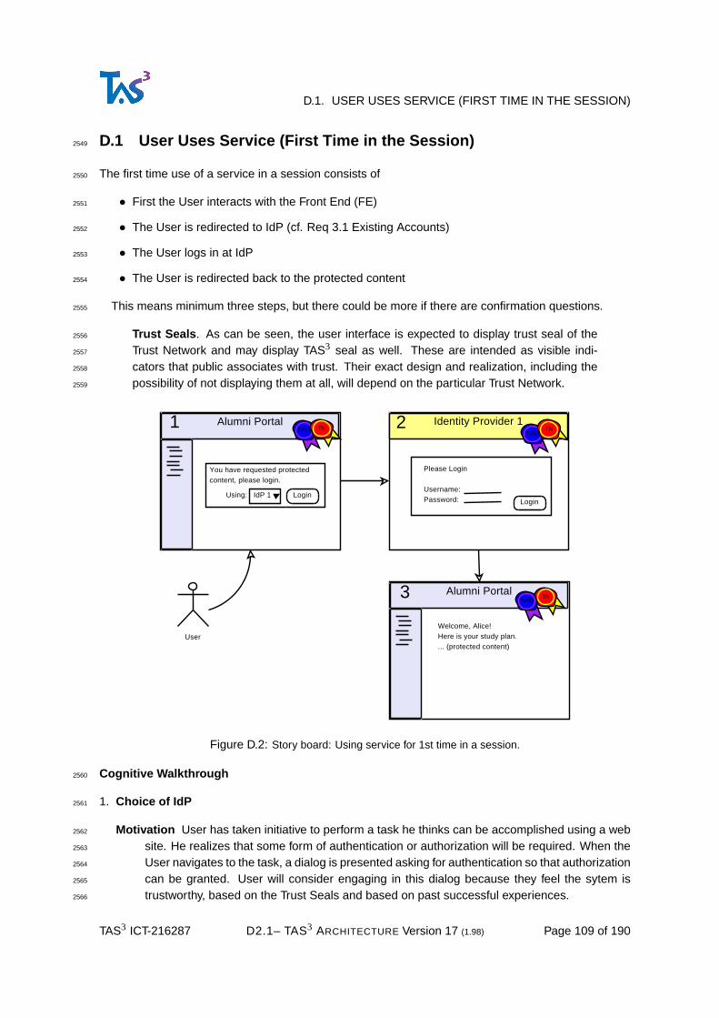
D.1. USER USES SERVICE (FIRST TIME IN THE SESSION)
D.1 User Uses Service (First Time in the Session)2549
The first time use of a service in a session consists of2550
• First the User interacts with the Front End (FE)2551
• The User is redirected to IdP (cf. Req 3.1 Existing Accounts)2552
• The User logs in at IdP2553
• The User is redirected back to the protected content2554
This means minimum three steps, but there could be more if there are confirmation questions.2555
Trust Seals . As can be seen, the user interface is expected to display trust seal of the2556
Trust Network and may display TAS3 seal as well. These are intended as visible indi-2557
cators that public associates with trust. Their exact design and realization, including the2558
possibility of not displaying them at all, will depend on the particular Trust Network.2559
Alumni Portal
Alumni Portal
Identity Provider 1
User
Welcome, Alice!Here is your study plan.... (protected content)
1 2
3
Please Login
Username:Password: Login
You have requested protectedcontent, please login.
LoginUsing: IdP 1
TAS3
TAS3
TAS3TN TN
TN
Figure D.2: Story board: Using service for 1st time in a session.
Cognitive Walkthrough2560
1. Choice of IdP2561
Motivation User has taken initiative to perform a task he thinks can be accomplished using a web2562
site. He realizes that some form of authentication or authorization will be required. When the2563
User navigates to the task, a dialog is presented asking for authentication so that authorization2564
can be granted. User will consider engaging in this dialog because they feel the sytem is2565
trustworthy, based on the Trust Seals and based on past successful experiences.2566
TAS3 ICT-216287 D2.1– TAS3 ARCHITECTURE Version 17 (1.98) Page 109 of 190

D.2. ALREADY-LOGGED-IN OPTIMIZATION (SSO)
Available and understandable User will be guided by modality of the interaction to a situation2567
where he will either have to proceed with selection of an IdP or will have to abandon the task.2568
Choosing another task that does not require authentication is also an option. The interaction2569
should be structured such that the requirement for authentication will become evident early2570
on, so that User avoids performing work only to find out that he is unable to proceed.2571
Feedback The available IdP choices that are presented should be as narrow and relevant as2572
possible. Federated SSO research recognizes IdP selection as a major problem. Once IdP is2573
chosen and button is pressed, clear feedback is provided that User has landed on the IdP web2574
site. The IdP screen should provide contextual information about the task which motivated the2575
authentication (such feedback is lacking in step 2 of Fig-D.2).2576
2. Login2577
Motivation User is in the mind set of completing a task and will perform this step if he reason-2578
ably can. This mind set is reinforced by IdP providing feedback as to what task requires the2579
authentication.2580
Biggest challenge and incovenience for the User will be the necessity to present authentica-2581
tion credentials. This inconvenience can be mitigated by use of Single Sign-On.2582
Available and understandable Availability of the logon and the acceptable forms of credentials2583
should be self-evident from the first screen of the IdP. First screen should lay visible all options2584
and avoid any hierarchical navigation to arrive to the desired option.2585
Feedback Successful authentication will lead to User being returned to the Front End web site.2586
This in itself is a form of feedback, but it should be reinforced by the web site providing a clear2587
welcome greeting, stating that the User has been authenticated (and possibly authorized as2588
well).2589
3. Login complete . This use case ends here, but an application specific use case will start here.2590
D.2 Already-Logged-in Optimization (SSO)2591
Same as above, but without IdP authenticating the user again. The flow does not need to stop at IdP2592
at all. Optimized SSO use case, showing the full convenience of SSO, leading to 2 step process.2593
2594
Cognitive Walkthrough2595
1. Choice of IdP : Same cognitive walkthrough as in previous section.2596
2. Login : No cognitive walkthrough needed as no user interface will be presented.2597
3. Login complete . This use case ends here, but an application specific use case will start here.2598
D.3 User Uses Dashboard2599
This use case addresses Reqs. D1.2-2.11-Transp and D1.2-3.3-Dash.2600
In this use case the user interacts with the TAS3 Dashboard in order to determine the status of a2601
business process he is engaged in. It consists of the following steps:2602
TAS3 ICT-216287 D2.1– TAS3 ARCHITECTURE Version 17 (1.98) Page 110 of 190

D.3. USER USES DASHBOARD
Job Agency
Job Agency
User
Welcome, Applicant!Here are your competencies.... (protected content)
1
3
You have requested protectedcontent, please login.
LoginUsing: IdP 1
Identity Provider 1
(2)
Session alreadyactive, no needto login again (SSO).
TAS3
TAS3
TN
TN
Figure D.3: Story board: Using further services after logging in at IdP - Single Sign-On (SSO).
• The user logs into the Dashboard (possibly using SSO)2603
• The user sees a page with an overview of the transactions2604
• The user drills down to visualise a particular business process.2605
• The user views a particular audit trail and discovers a suspect item.2606
• The user requests a legally binding audit statement about the transaction.2607
• Competent authority requests further information about the transaction from the Service Provider2608
that holds the detailed audit trail.2609
Cognitive Walkthrough2610
1. Engaging Dashboard and Choice of IdP2611
Motivation User has taken initiative to find out about the state of some business process or the2612
handing of his PII. User understands, due to training or awareness campaigns, or because2613
a noice was given in the beginning of the business process, that this is possible. User may2614
have found out about the possibility by surfing the web or through a search engine. The mere2615
possibility may spark the User’s interest and get him to try the Dashboard out. User may2616
also have noticed an irregularity or complained to some instance and been told to consult his2617
Dashboard.2618
Available and understandable Since User is assumed to take initiative, a major hurdle will be2619
how the user finds out about the Dashboard and how to contact it. Some possibilities2620
TAS3 ICT-216287 D2.1– TAS3 ARCHITECTURE Version 17 (1.98) Page 111 of 190
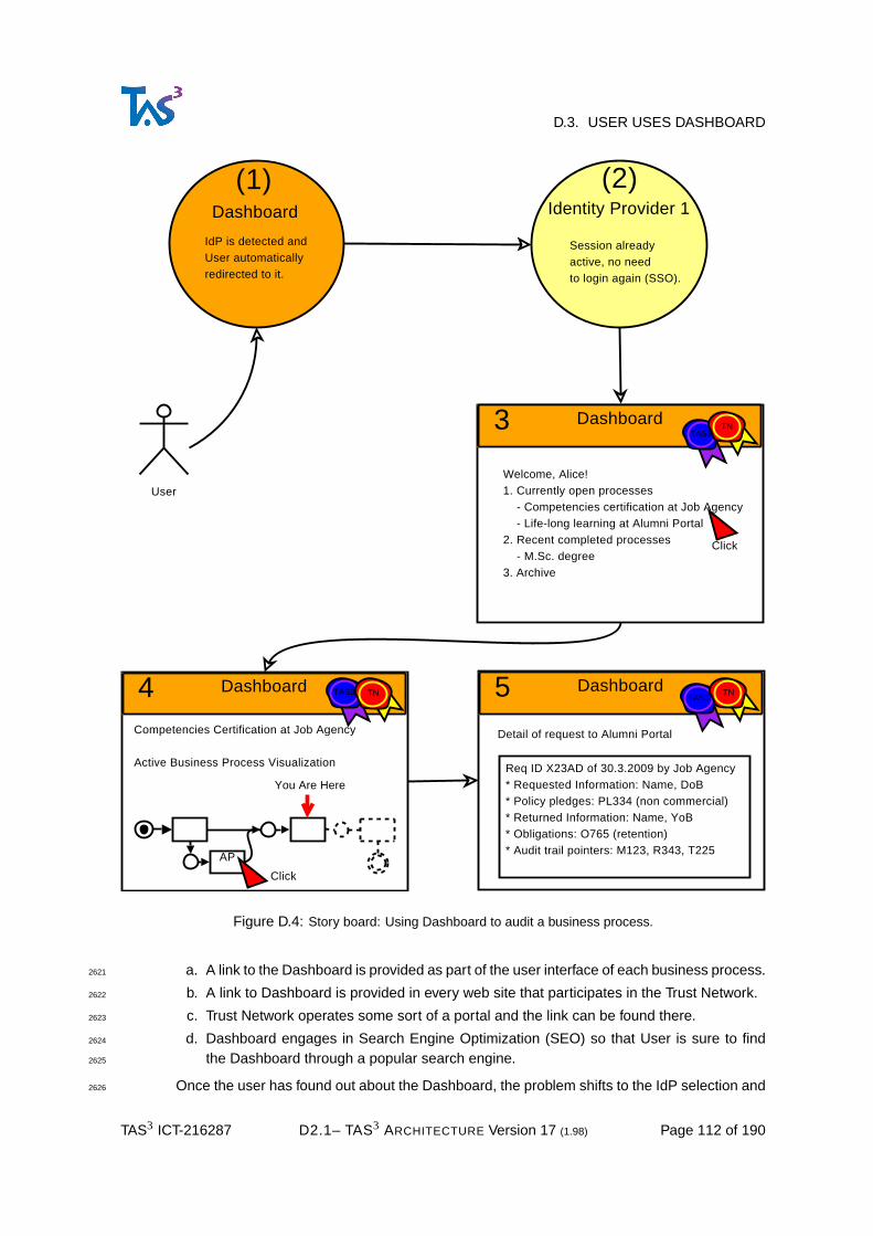
D.3. USER USES DASHBOARD
Dashboard
User
Welcome, Alice!1. Currently open processes - Competencies certification at Job Agency - Life-long learning at Alumni Portal2. Recent completed processes - M.Sc. degree3. Archive
3
Identity Provider 1
(2)
Session alreadyactive, no needto login again (SSO).
Dashboard
(1)
IdP is detected andUser automaticallyredirected to it.
Dashboard
Competencies Certification at Job Agency
Active Business Process Visualization
4 Dashboard
Detail of request to Alumni Portal
5
AP
You Are Here
Click
Click
Req ID X23AD of 30.3.2009 by Job Agency* Requested Information: Name, DoB* Policy pledges: PL334 (non commercial)* Returned Information: Name, YoB* Obligations: O765 (retention)* Audit trail pointers: M123, R343, T225
TAS3
TAS3TAS3
TN
TNTN
Figure D.4: Story board: Using Dashboard to audit a business process.
a. A link to the Dashboard is provided as part of the user interface of each business process.2621
b. A link to Dashboard is provided in every web site that participates in the Trust Network.2622
c. Trust Network operates some sort of a portal and the link can be found there.2623
d. Dashboard engages in Search Engine Optimization (SEO) so that User is sure to find2624
the Dashboard through a popular search engine.2625
Once the user has found out about the Dashboard, the problem shifts to the IdP selection and2626
TAS3 ICT-216287 D2.1– TAS3 ARCHITECTURE Version 17 (1.98) Page 112 of 190

D.3. USER USES DASHBOARD
authentication. In Fig-D.4 we have assumed that IdP can be detected and User is already2627
logged in, as the case typically would be immediately after engaging some Front End (e.g.2628
the Job Agency).2629
However, if time has passed, user may need to choose explicitly an IdP and explicitly authenti-2630
cate, as in Section "User Uses Service (First Time in the Session)". A confusing situation can2631
arise where user has tried to access the Dashboard, but the first screen he sees is the IdP2632
authentication screen (because IdP detection worked, but user was not logged in yet). This2633
situation should be mitigated either by IdP providing enough context about the operation that2634
is motivating the authentication, or by the Dashboard imposing a splash screen even when2635
IdP choice is already known.2636
Feedback If IdP was detected and user was already logged in, the first feedback will be Dashboard2637
logged in welcome screen. If authentication is needed, then the IdP context message or the2638
splash screen solutions should be adopted, as described in the previous paragraph.2639
2. Login : no specific cognitive walkthrough requirements. See discussion in in the First Time use2640
case.2641
3. Choose Business Process to Audit2642
Motivation User set out on his quest to perform this task.2643
Available and understandable The list of the business process instances should be structured so2644
that all business process instances are reachable while at the same time the processes user is2645
most likely to be interested in are presented first or more prominently. Due to potentially large2646
number of processes, we may need to resort to hierarchy or search functions. An ontology of2647
business processes will help in setting up the hierachy and search.2648
The business processes should be titled and described in language that the User can relate2649
to. In particular, while codes can be provided for accuracy and reference, every business2650
process should have a human readable name. The resultant translation issues will have to be2651
recognized and addressed.2652
Feedback Choice of a business process instance will lead to its visualization where User can2653
clearly identify What, Who, When, and similar information so that user can confirm he has2654
made the right choice. If choice was wrong, User should easily be able to choose another2655
instance.2656
4. Choose Detail of Business Process Instance to Audit2657
Motivation Once user sees visualization of the business process instance, he will need to drill2658
down to relevant detail. This may be driven by User’s curiosity or perceived notion of culpable2659
part.2660
Available and understandable The visualization has to be structured so that it honestly depicts2661
the essence of the business process without cluttering the view with details that can be2662
reached later. Every step that User is expected to perform (or has already performed) should2663
be visible as well as major processing steps that are not in User’s control, especially those2664
that involve transfer or manipulation of PII.2665
All descriptions of the steps should be succinct and in human language, with translation issues2666
addressed. Codes and references for the instance and steps can be provided for accuracy,2667
but these should never supplant the human description.2668
TAS3 ICT-216287 D2.1– TAS3 ARCHITECTURE Version 17 (1.98) Page 113 of 190

D.4. IDP DETECTED-OPTIMIZATION (SSO)
To assist User in drilling into detail, the user interface should make it patently evident where2669
this possibility exists, e.g. by using high-lighting techniques.2670
Feedback User is assisted in contemplating the choice of drill-in by high-lighting of available op-2671
tions. Once a step is chosen for scrutiny, user will see visualization of that step in great detail.2672
The visualization will be titled in such a way that it is evident to the User that it pertains to the2673
step he chose in the business process instance overview.2674
5. View detail and request audit item from Front End2675
Motivation User needs to get evidence about a step of a process2676
6. View audit item (not depicted in the figure)2677
7. Escalate (not depicted in the figure) (Req. D1.2-6.9-Complaint)2678
D.4 IdP Detected-Optimization (SSO)2679
Job Agency
User
Welcome, Applicant!Here are your competencies.... (protected content)
3
Identity Provider 1
(2)
Session alreadyactive, no needto login again (SSO).
Job Agency
(1)
IdP is detected andUser automaticallyredirected to it.
TAS3 TN
Figure D.5: Story board: Fully automatic login - Single Sign-On (SSO) - when IdP can be detected.
This flow, see Fig-D.5, can further optimize the already logged in case by allowing the Job Agency to2680
detect that the user has already chosen IdP and therefore use the IdP to log the User in automatically.2681
Essentially the ceremony becomes a one step process.2682
D.5 User Uses Service, Identity Selector Case2683
In the Identity Selector flow, see Fig-D.6, the User never interacts with the IdP directly. Instead, the2684
Identity Selector provides a user interface (step 3) for the IdP to query authentication credentials. User2685
TAS3 ICT-216287 D2.1– TAS3 ARCHITECTURE Version 17 (1.98) Page 114 of 190

D.5. USER USES SERVICE, IDENTITY SELECTOR CASE
Job Agency
Job Agency
User
Welcome, Applicant!Here are your competencies.... (protected content)
1
4
You have requested protectedcontent, please login usingIdentity Selector
Login
Identity Selector2Choose Identity Provider for This Transaction:
Identity Selector3
Please Login to IdP1
Username:Password: Login
Aliceat
IdP1
Aliceat
IdP2
Click
TAS3
TAS3
TAS3 TAS3
TN
TN
TN TN
Figure D.6: Story board: Identity Selector provides IdP User Interface.
experience is entirely managed by the "ceremony" that the Identity Selector presents.2686
Alumni Portal
User
2
Please Login
Username:Password: Login
Job Agency
Welcome, Applicant!Here are your competencies.... (protected content)
3
Job Agency1
Please Login
Username:Password: Login
TAS3 TAS3
TAS3
TN
TN
TN
Figure D.7: Story board: Using services with local login (not recommended).
TAS3 ICT-216287 D2.1– TAS3 ARCHITECTURE Version 17 (1.98) Page 115 of 190

D.6. USER USES SERVICE, LOCAL LOGIN CASE
D.6 User Uses Service, Local Login Case2687
N.B. This use case is not recommended. You should use SSO based approaches instead.2688
We document it here only to illustrate the problems associated with multiple logins.2689
The assumption is that the user will use more than one service. This highlights the inconvenience2690
of user having to authenticate separately to each service. There are further complications under the2691
hood, not least of which are privacy threats. This scenario could be called explicit account linking.2692
While we consider supporting this scenario to be in scope, we do not recommend it unless there is no2693
alternative, or as temporary solution.2694
D.7 User Uses Service, Proxy IdP Case2695
This sequence, see Fig-D.8, illustrates the experience of a user logging in to SP that does not directly2696
trust his IdP. The trust is mediated by the "middle" IdP that SP trusts.2697
Job Agency
User
Welcome, Applicant!Here are your competencies.... (protected content)
4
Job Agency
(1)
IdP is chosen by JobAgency’s trust relationship,
without user input.
Identity Provider 12
Identity Provider 23
Please Login
Username:Password: Login
Please choose your home IdP.
LoginUse: IdP 2
TAS3
TAS3TAS3TN TN
TN
Figure D.8: Story board: Login using IdP not trusted by Job Agency.
This sequence can be further optimized if the middle IdP can somehow automatically detect which2698
IdP is the home IdP (similar to Section IdP Detected Optimization SSO) and, of course, if the User is2699
already logged in the SSO optimization of Section Already Logged-in Optimization SSO.2700
D.8 Consenting to PII Release or Manipulation2701
This section addresses Reqs. D1.2-6.3-WhatHowWhyWho, D1.2-6.6-Consent, D1.2-6.7-Reconsent,2702
D1.2-4.1-EnfUCPol.2703
TAS3 ICT-216287 D2.1– TAS3 ARCHITECTURE Version 17 (1.98) Page 116 of 190

D.8. CONSENTING TO PII RELEASE OR MANIPULATION
D.8.1 Interaction on Front Channel2704
The obvious choice of having the requesting SP collect User’s consent has an obvious conflict of2705
interest issue. In some legal contexts this may be acceptable, but in general we need a way for either2706
the releasing party or some Trusted Third Party to collect the consent.2707
Alternatively, not shown here, the user may explicitly provide his consent by authenticating to the re-2708
leasing party and authorising it to release the PII to the SP. Further user cases for accessing releasing2709
parties who are repositories and authorising third party access to repository contents are provided in2710
[TAS3D42Repo].2711
Cognitive Walkthrough2712
1. IdP choice as usual2713
2. Authentication as usual2714
3. User triggers action, as usual2715
4. Consent to release of PII2716
Motivation User will be motivated to take action because it is imposed to him by the modal flow of2717
the interaction. User will be pleased to take action because asking consent is in his protection,2718
but Users do get annoyed if you ask too often - to solve this we would need Privacy Agent,2719
whose Use Cases are to be elaborated later (M30 D2.1?).2720
Available and understandable Presentation of the consent question is a major challenge. It2721
needs to be succinct, yet comprehensive and legally binding. Some Users will want high2722
degree of detail and control, while others will be confused by too many options. Fig-D.9 de-2723
picts a dummied-down interface. This may not be appropriate for some users.2724
Feedback Once consent is given, User lands on page that uses the consented information. This2725
may be sufficient in its own right, but could be enhanced by high-lighting the information on2726
the page the user just consented to.2727
5. Business process continues with the PII as usual2728
D.8.2 Interaction on side channel2729
This Use Case is similar to the previous one. Only difference is that the consent is asked using a Side2730
Channel, such as mobile phone or instant messaging. The side channel provides an independent2731
means of communication, a type of second factor to the consent.2732
The Side Channel approach can also be convenient when consent needs to be asked deep in SOA2733
Web Services calls where Front Channel is not available.2734
In User-not-present transaction the Side Channel may be the only option for asking user’s consent,2735
or else the business process needs to be stopped until user provides consent via Dashboard.2736
D.8.3 Interaction via Dashboard2737
In User-not-present transaction the business process may stop until user provides input or consent via2738
Dashboard. This alternative will be covered in a future version of this document.2739
TAS3 ICT-216287 D2.1– TAS3 ARCHITECTURE Version 17 (1.98) Page 117 of 190

D.8. CONSENTING TO PII RELEASE OR MANIPULATION
Job Agency
Job Agency
User
Welcome, Applicant!Here are your competencies.... (protected content)
1
3
You have requested protectedcontent, please login.
LoginUsing: IdP 1
Identity Provider 1
(2)
Session alreadyactive, no needto login again (SSO).
Job Agency
Detail of competencyprovided fromUniversity.
5
Refresh
PII Consent4
Job Agency wants to knowyour competencies. Pleaseconsent to release of:
[x] High school grades[x] University diploma
Cancel
Consent
TAS3
TAS3
TAS3
TAS3
TN
TN
TN
TN
Figure D.9: Story board: Presenting a PII consent question in Front Channel interaction.
TAS3 ICT-216287 D2.1– TAS3 ARCHITECTURE Version 17 (1.98) Page 118 of 190

D.8. CONSENTING TO PII RELEASE OR MANIPULATION
Job Agency
Job Agency
User
Welcome, Applicant!Here are your competencies.... (protected content)
1
3
You have requested protectedcontent, please login.
LoginUsing: IdP 1
Identity Provider 1
(2)
Session alreadyactive, no needto login again (SSO).
Job Agency
Detail of competencyprovided fromUniversity.
5
Refresh
Job Agency(4)
Please wait while your consentis asked via mobile phone.
Cancel
Job Agency wants to knowyour competencies. Pleaseconsent to release of:[x] High school grades[x] University diplomaReply to this SMS withcode x98sd1 if you agree.[Reply]
SMS
SMS
C
TAS3
TAS3
TAS3
TAS3
TN
TN
TN
TN
Figure D.10: Story board: Presenting a PII consent question using Side Channel interaction.
TAS3 ICT-216287 D2.1– TAS3 ARCHITECTURE Version 17 (1.98) Page 119 of 190

D.9. USING LINKING SERVICE
D.9 Using Linking Service2740
1. The Linking Service should be user friendly. It may be the only interface that users see for linking2741
their attributes together (other approaches are possible, see "pull model").2742
2. A welcome screen explains the purpose of the Linking Service and guides the user through the2743
process of attribute linking.It has2744
a. Picking list for choosing IdP2745
b. "Connect" button2746
c. "View linked accounts" button2747
d. "Make linked accounts available to services" button2748
e. Notice or pledge about respecting User’s privacy2749
3. When the user selects the "Connect" button, the linking service will redirect the user to the selected2750
IdP, allowing the user to login. After login, the user will be redirected back to the linking service2751
welcome screen.2752
4. When the user selects "View my linked accounts" he will be presented with the screen with2753
a. A table containing two columns, labelled "Organisation" and "Temporary Account Identifier" and2754
at the left hand side by each table entry will be a tick box that the user can tick to remove the2755
linked account. Above the column of tick boxes will be the word Delete.2756
b. "Delete" button, which will remove the chosen accounts from the table and return the user to this2757
page2758
c. "Home Page" button, which will take the user to Welcome screen2759
d. "Make my linked accounts available to services" button, which will take the user to the next2760
screen.2761
e. Notice or pledge about respecting User’s privacy2762
5. When the user selects the "Make my linked accounts available to services" button he will be pre-2763
sented with a screen containing2764
a. An explanation about opt-in in the linking (if you do not make accounts available, the default will2765
be no linking).2766
b. A table with 3 columns and a delete tick box beside each row of the table. The table columns are2767
"Service", "Organisation" and "Temporary Account Identifier". The table will always be empty for2768
new users when they first approach this screen.2769
c. A picking list of all the services in the federation, obtained from the metadata of the federation.2770
The first entry in the list will be "All Other Services".2771
d. Once the user selects a service provider or "All Other Services" from the picking list, a picking2772
list of all the IdPs that are currently linked together and that appear in the table of the My2773
Linked Accounts Screen, minus the IdPs that have already been paired with the selected service2774
provider is displayed.2775
TAS3 ICT-216287 D2.1– TAS3 ARCHITECTURE Version 17 (1.98) Page 120 of 190

D.10. CHOOSING AMONG MULTIPLE SERVICE PROVIDERS
The first row of this picking list will be "All My Linked Accounts". The user will then pick one of2776
his linked accounts or "All My Linked Accounts". If the user picks "All My Linked Accounts" a2777
wild card will be inserted into the third column. If the user picks one of his accounts then the2778
third column will be automatically completed with the account Persistent ID unless the user has2779
two or more accounts at the same IdP, in which case the third column will contain a picking list2780
of Persistent IDs sent from that IdP, minus any already selected for this service provider.2781
It is important that the table always lists the service providers in alphabetical order so that the2782
user can easily see which links he has set up for which SPs, and for every SP, the linked IdPs2783
are in alphabetical order.2784
e. "Delete" button, which will remove the chosen accounts from the table and return the user to this2785
page2786
f. "Home Page" button, which will take the user to Welcome screen2787
g. "View my linked accounts" button, which will take the user to the screen referred to in step (4),2788
above.2789
D.10 Choosing among Multiple Service Providers2790
Sometimes user will have choice of multiple possible providers for a given service. In this situation2791
Trust and Privacy Negotiation function can be used to narrow down the list. If after narrowing down2792
more than one choice still remains, it may be reasonable to ask the user to make the choice.2793
D.10.1 Simple Choice of Provider2794
Cognitive Walkthrough2795
1. IdP choice as usual2796
2. Authentication as usual2797
3. User triggers action, as usual2798
4. Choose Service Provider2799
Motivation The decision point will be imposed to the user through modal user interaction. User2800
will be motivated to make the choice as he may guard different information, e.g. different2801
personae, at different Attribute Authorities.2802
Available and understandable User’s choice should only be solicited if there is genuine choice.2803
System should implement automatic discovery and detection as much as possible.2804
The choices should be formulated in human language, with translations as appropriate.2805
Feedback Once User makes his choice, he will land on the requestor’s page. This in itself may2806
be sufficient feedback, but indicating on the page where the information came from is recom-2807
mended.2808
TAS3 ICT-216287 D2.1– TAS3 ARCHITECTURE Version 17 (1.98) Page 121 of 190

D.10. CHOOSING AMONG MULTIPLE SERVICE PROVIDERS
Job Agency
Job Agency
User
Welcome, Applicant!Here are your competencies.... (protected content)
1
3
You have requested protectedcontent, please login.
LoginUsing: IdP 1
Identity Provider 1
(2)
Session alreadyactive, no needto login again (SSO).
Job Agency
Detail of competencyprovided fromUniversity.
5
Refresh
Job Agency4
Your competencies are availablefrom multiple sources.Please choose:
UniversityEmployer
Get
Cancel
TAS3
TAS3
TAS3
TAS3
TN
TN
TN
TN
Figure D.11: Story board: Choice of Service Provider.
D.10.2 Trust and Privacy Negotiation Assisted by User Interaction2809
Cognitive Walkthrough2810
1. IdP choice as usual2811
TAS3 ICT-216287 D2.1– TAS3 ARCHITECTURE Version 17 (1.98) Page 122 of 190

D.10. CHOOSING AMONG MULTIPLE SERVICE PROVIDERS
Job Agency
Job Agency
User
Welcome, Applicant!Here are your competencies.... (protected content)
1
3
You have requested protectedcontent, please login.
LoginUsing: IdP 1
Identity Provider 1
(2)
Session alreadyactive, no needto login again (SSO).
Job Agency
Detail of competencyprovided fromUniversity.
5
Refresh
Trust and Privacy Negotiator4
Your competencies are availablefrom multiple sources.Please choose trustworthy:
University (T=9)Employer (T=4)
Get
Cancel
TAS3
TAS3
TAS3
TAS3
TN
TN
TN
TN
Figure D.12: Story board: Trust and Privacy Negotiation with User Interaction.
2. Authentication as usual2812
3. User triggers action, as usual2813
4. Negotiate appropriate supplier for service or information2814
TAS3 ICT-216287 D2.1– TAS3 ARCHITECTURE Version 17 (1.98) Page 123 of 190

D.11. USER-NOT-PRESENT TRANSACTION
Motivation User will be forced to the decision point by modal user interface flow. User will be2815
motivated to make a choice either because he has no prior relationship with proposed SPs2816
and he needs to rely on trust preceptions, or because user wants to be in control and avoid2817
machine deciding for him.2818
Available and understandable Presenting complex trust based decision is not easy. This topic2819
will be further researched during TAS3 project.2820
Feedback Once User makes his choice, he will land on the requestor’s page. This in itself may2821
be sufficient feedback, but indicating on the page where the information came from is recom-2822
mended.2823
Further Use Cases depicting complex Trust and Privacy Negotiations will be elaborated in other2824
project deliverables.2825
D.11 User-Not-Present Transaction2826
User-not-present scenario can be driven in three ways:2827
1. User has been present in some earlier time and authorized, indirectly, the transaction. Audit trail2828
MUST show this authorization.2829
2. There is an over-arching legal or legitimate business requirement. Existence of such requirement2830
MUST be demonstratable from the audit trail.2831
3. "Break the glass" scenarios. Again audit trail MUST capture legitimate reason why the scenario2832
was invoked and the audit trail should be especially detailed about the actions performed under the2833
break the glass authority.2834
Actual triggering of the event will depend on a business process. To gain acute authorization to2835
execute the operation, the business process will have to declare its intent and show evidence why it2836
should be authorized (see (1) and (2), above). Then, the operation MUST be thoroughly recorded in2837
the audit trail.2838
User’s only contact point with User-Not-Present transaction is to audit it after the fact using the2839
Dashboard.2840
D.12 User Present Delegation2841
See Fig-D.13.2842
• Problem of choosing to whom to delegate, buddy list visualization2843
- How to obtain human readable names without violating privacy of the buddies?2844
Delegation of permissions to access repositories is addressed more fully in [TAS3D42Repo].2845
TAS3 ICT-216287 D2.1– TAS3 ARCHITECTURE Version 17 (1.98) Page 124 of 190

D.13. USER-NOT-PRESENT DELEGATION
Alumni Portal
Delegation Server A
Alice
4
5
Send InvitationTo: BobResource: Alice’s ePortfolioInvite: http://alumni.ex/x23a
Alumni Portal
Alumni Portaldetect IdP 1
IdP 1Authenticates
Alice
Share
Alice’sePortfolio
1
3
2
Send
Bob
Alumni Portal
Welcome, Bob!Here is Alice’s study plan.... (protected content)
8
IdP 2Authenticates
Bob
6
You have requested protectedcontent, please login.
LoginUsing: IdP 2
Delegation Server A7
Accept InvitationFrom: AliceResource: Alice’s ePortfolio[x] Invite Alice
Accept
TAS3
TAS3
TAS3
TAS3
TAS3
TN
TN
TN
TN
TN
Figure D.13: Story board: Alice invites Bob to view her ePortfolio.
D.13 User-Not-Present Delegation2846
This will cover situations such as administrative or judicial decisions that result in delegation without2847
the User necessarily wanting the delegation to happen.2848
TAS3 ICT-216287 D2.1– TAS3 ARCHITECTURE Version 17 (1.98) Page 125 of 190

D.14. OTHER USE CASE WORK
We will explore these use cases in more detail in a future deliverable (M30 D2.1).2849
D.14 Other Use Case Work2850
[TAS3D42Repo] has an extensive section on use cases, which should be viewed as a complement or2851
extension of what is presented here.2852
[TAS3D14DESIGNREQ] has some usage scenarios, especially relating to the pilots, although they2853
are not refined into use cases.2854
D.15 Future Use Case Work2855
Some other User Cases we may elaborate on, or that will be elaborated in other TAS3 deliverables,2856
include:2857
• Full elaboration of the Trust and Privacy Negotiation Use Case(s)2858
• SP BPel4People UI2859
• Trust Guarantor UI2860
• SP registration process UI2861
• Bulletin board UI’s2862
• Statistical services from anonymised data UI2863
• Situation where additional data request deep in the recursive Web Services or business process2864
requires Step-Up authentication2865
• Processes that may take long time and have start stop states taking longer than a web service2866
call can be reasonably expected to take.2867
BPEL engine can monitor this: any timeout is service failure and recorded as such. All service2868
providers must agree to terms SLA on sign up to TAS3 network and a key element of this will be2869
service reliability and performance.2870
- Human steps in process flow can be slow (e.g. process can be waiting sometimes for days2871
/ weeks)2872
• Use case: User wants to audit and complain2873
- like on ebay give negative feedback and influence reputation of Service Provider2874
- Complaining to wrong entity2875
- Misidentifying probable cause2876
- Ability trace all the way to the legal evidence2877
• 3rd party wants to audit or demonstrate that something happened,2878
- nonrepudiation2879
TAS3 ICT-216287 D2.1– TAS3 ARCHITECTURE Version 17 (1.98) Page 126 of 190

D.15. FUTURE USE CASE WORK
- articulation to proof in law suits2880
• Registering a new service to the trust network2881
TAS3 ICT-216287 D2.1– TAS3 ARCHITECTURE Version 17 (1.98) Page 127 of 190

2882
Annex E: TAS3 Business Model (Non-Normative)2883
This Annex has been moved to the end of the PDF document. In future the business model will be2884
maintained and published as a separate document.2885
TAS3 ICT-216287 D2.1– TAS3 ARCHITECTURE Version 17 (1.98) Page 128 of 190

2886
Annex F: Threats (Non-Normative)2887
This section addresses Reqs. D1.2-2.7-Safe and D1.2-2.8-Avail. Also Req. D1.2-2.9-Correct is2888
touched from secure programming perspective.2889
F.1 Other work2890
• [SAML2security]2891
• [IDWSFSecPriv]2892
• [NIST-SP800-30]2893
• [Meier09] provides a check list and [Meier08] a short list2894
F.2 Business threats2895
T21-IDTheft Identity Theft2896
T22-Illegal Illegal transactions2897
F.3 Trust model threats2898
T31-OverPrivil Over-privileged process and service accounts.2899
T32-UnTTP Untrustworthy Third Party.2900
F.4 Architectural threats2901
T41-BPMflaw Business process modelling flaws. How to audit or validate the model?2902
T42-BPMdel Accidental deletion of process steps such as authorization or validation2903
T43-Berserk Dynamically adaptive business process gone wild2904
F.5 Trust misconfiguration threats2905
T51-TNins Insertion of illegitimate members in trust network.2906
T52-Mole Moles in trust network. A previously trusted member turns into rougue. How to detect?2907
How to rectify?2908
T55-PolluteRep Pollution of reputation of other party2909
T56-Augment Illicit augmentation of reputation by party itself2910
TAS3 ICT-216287 D2.1– TAS3 ARCHITECTURE Version 17 (1.98) Page 129 of 190

F.6. PROTOCOL MISCONFIGURATION THREATS
T57-Deface Defacing Front End web site can cause damage to reputation of the Front End. Defacing2911
attacks can happen through same means as phising (T111-Phish) and also through break-ins,2912
either through network, or physical.2913
T58-WrongCAs Insertion of wrong CAs into a trust network2914
T59-WrongAAs Wrongly assigning source of authority to an attribute authority2915
T510-WrongLOA Wrong assertion of LOA value by an IDP2916
F.6 Protocol misconfiguration threats2917
T61-Replay Replay attack. See CR211-Uniq.2918
T62-UnEncLink Unencrypted links e.g. SSLnull cipher suites.2919
T63-UnAnLink Unauthenticated links2920
F.7 Authorization misconfiguration threats2921
T71-WrongGrant Returning grant instead of deny leading to unauthorised access2922
T72-WrongDeny Returning deny instead of grant leaving to DOS.2923
T73-WrongObs Returning wrong obligations2924
T74-MissingObs Missing obligations from authz decisions2925
T75-OKAC Attribution of wrong access rights to an otherwise trusted member2926
F.8 Ontology threats2927
T81-SameButDiff Same term meaning different things to two parties leads to illicit access, due to2928
wrong rule inadvertently matching.2929
F.9 Exposure threats2930
T91-Eavesdrop Exposure of data due to network sniffing or eavesdropping. Counter measure: en-2931
crypt data and manage keys right.2932
T91-DBLeak Exposure of data due to database files or transaction logs. Counter measure: encrypt2933
data and manage keys right.2934
T92-TamperNet Modification of data in transit. Counter measuers: signing or verification of a hash2935
over the data.2936
T93-TamperDB Modification of data in database.2937
TAS3 ICT-216287 D2.1– TAS3 ARCHITECTURE Version 17 (1.98) Page 130 of 190

F.10. PRIVACY THREATS
T94-ExptLeak Error condition or exception reveals too much data or system details (usually to aid2938
debugging). Exception output that appears in user interface or over the network is especially2939
damning. Leakage to logs is also a threat.2940
T95-CoreLeak Error condition or exception causes a core dump that reveals too much data or system2941
details (usually to aid debugging).2942
F.10 Privacy threats2943
T101-LeakBackup Eavesdropping on backups (see CR213-Backup)2944
T102-Correlation Database correlation by colluding entities (solution: do not leak correlation handles,2945
i.e. use pseudonyms - see Architecture, Core Security Architecture, Access Credentials, Pull2946
Model)2947
T103-TAIdP IdP collects traffic analysis (and then sells or illicitly use it). Some counter measures:2948
• TN wide data retention policy, audit this: add compliance requirement2949
• Pure play IdP operator vs. mixed functions2950
• Centralized IdP well managed may be a good idea2951
T104-TADI Disco collects traffic analysis (and then sells or illicitly use it)2952
T105-TA3rd Traffic Analysis by Third Party2953
T106-CorrAudit Correlation handles of audit trail will also become correlation handles.2954
T107-LogTokLeak If WSC parties keeps log of User’s pseudonym along with encrypted form of User’s2955
identifier at WSP, then WSC and WSP can correlate and collude using the encrypted form.2956
However this threat is acute only between directly interacting parties. In a chain of web services2957
calls longer than 3, the nonneiboughring parties are not in position to collude using this attack.2958
Current solution is to forbid logging the tokens, see CR53-DontLogTok.2959
T108-PhishPII Tricking user to reveal PII through phising attack that poses a real looking web page2960
to solicit PII. See also access version of the threat: T111-Phish.2961
T109-SocEngPII Social Engineering, talking users to revealing PII. See also access version of the2962
threat: T112-SocEng.2963
T1010-SnoopPII Network eavesdropping to record PII.2964
T1011-KbdLogPII Keyboard logger or other malware to record credentials.2965
T1012-MalwarePII PII theft, e.g. copy private contact book, using malware.2966
T1013-PIITheft Physical theft of PII.2967
TAS3 ICT-216287 D2.1– TAS3 ARCHITECTURE Version 17 (1.98) Page 131 of 190

F.11. AUTHENTICATION THREATS
F.11 Authentication threats2968
T111-Phish Tricking user to reveal his authentication credentials through phising attack that poses a2969
real looking web page to solicit user’s access credentials. This could be created through2970
a. DNS manipulation2971
b. Cross site scripting2972
c. Inappropriate insertion of content in legitimate site2973
d. Containment of legitimate site in illegitimate frame2974
See also PII version of threat: T108-PhishPII.2975
T112-SocEng Social Engineering, talking users to revealing access credentials.2976
See also PII version of threat: T109-SocEngPII.2977
T113-SnoopCred Network eavesdropping to record credentials.2978
T114-KbdLog Keyboard logger or other malware to record credentials.2979
T115-Malware Credential theft, e.g. copy private key, using malware.2980
T116-Theft Physical credential theft.2981
T117-Dict Dictionary attack on password2982
T118-Brute Brute force attacks of simply trying out all credentials.2983
T119-Cookie Cookie replay attack. Use previously recorded cookie in context where authentication2984
did not happen. Also arises if expired session cookie is allowed as a factor in authentication,2985
resulting stronger factor not being demanded.2986
T1110-Lure Luring users to do stupid things like2987
a. Visit web sites that phish or contain malware2988
b. Install malware and troians2989
c. Voluntarily give out credentials or PII2990
F.12 Impersonation threats2991
T121-Gift Users giving away their credentials to others2992
T122-Loss Users losing their credentials2993
T123-Careless Users not protecting their credentials properly e.g. posting passwords on post-it stick-2994
ers2995
T124-Delegation Authentication delegation models in which the delegate assumes the user’s original2996
ID instead of using their own (e.g. as in Shibboleth see https://spaces.internet2.edu/display/ShibuPortal/Solution+Proposal)2997
TAS3 ICT-216287 D2.1– TAS3 ARCHITECTURE Version 17 (1.98) Page 132 of 190

F.13. REPUDIATION THREATS
F.13 Repudiation threats2998
T131-Repud Repudiation of events by any party (system entity or user).2999
F.14 Unauditability threats3000
T141-AltSig Alteration of signed message (see CR27-Sig and CR28-Vfy)3001
T142-Tamper Alteration of audit trail (see CR212-Trail)3002
T143-LeakLogs Eavesdropping on logs (see CR212-Trail)3003
T144-NoAud Insufficient auditing in the first place3004
F.15 Software bug threats3005
T151-Overflow Buffer overflow attack, to gain injection and execution of code, usually leading to3006
compromise of the machine. Also heap overflow.3007
T152-Inject SQL Query Injection attack, causing database engine to execute unauthorized database3008
statements. This threat also covers similar attacks on other databases or downstream services3009
like shell scripts (command injection).3010
T153-NI Access control, signature verification, or other security feature not implemented. Testing only3011
positive cases can easily ignore this type of threat. It is imperative that the test suites also3012
include negative testing.3013
T154-Input Input MUST at all times be validated to conform to the expected syntax, and input in3014
general should never be trusted unless there is a cryptographical or structural guarantee of3015
trustworthiness. Some particular perils3016
a. Explicit inputs3017
b. Environment variables3018
c. URL and query string3019
d. CGI form fields3020
e. Cookies3021
f. HTTP headers3022
g. SOAP headers3023
h. Processing contexts of all sorts passed between software modules3024
i. Fields of certificates (from untrusted source, but you would not know until you manipulated3025
the certificate to find out if it is trusted).3026
j. Metadata3027
k. Messages from event bus3028
TAS3 ICT-216287 D2.1– TAS3 ARCHITECTURE Version 17 (1.98) Page 133 of 190

F.16. SERVICE AVAILABILITY THREATS
l. Data coming from database (even if database is supposed to be trusted, it may have been3029
compromised, thus checking for proper format will help to detect the breach and contain3030
it).3031
m. Deserialization of any data. This is particularly acute whan using eval to deserialize JSON3032
data.3033
Perl(1) tainted feature provides a way to track untrusted user input. All untrusted input MUST3034
be scrutinized for attack vectors, such as directory climbing (".." or " " = home directory) as a3035
path component. Where relative path is expected, an absolute path - one starting by "/" - MUST3036
NOT be allowed. All shell(1) or SQL escape characters (see also T152-Inject) are of highest3037
suspicion until proven to be secure.3038
When validating input, preferred strategy is to test if input is good and anything that does not3039
pass is bad. The alternative strategy of looking for known bad things (like ".." in path) is much3040
weaker and prone to errors.3041
T155-Mem Code MUST NOT3042
a. Dereference a Null Pointer3043
b. Use Freed Memory3044
c. Doubly Free Memory3045
T156-Fmt Format string mismatch. In printf(3) format string it is easy to get the format specifiers and3046
actual arguments mixed, resulting inappropriate format specifier being used for a given piece of3047
data.3048
T157-Trunc Truncation of value. Sometimes truncated value can have different meaning.3049
T158-Signed Signed conversion of a value that may not have been identified.3050
T159-CliValid Reliance on client side validation is no good for server as an alternate client will not per-3051
form the validation. Server MUST at all times perform all security critical validations. Client side3052
validation has value in (i) improving user experience and feedback, (ii) reducing network traffic3053
by not submitting obviously invalid inputs, (iii) protecting client side processing like AJAX appli-3054
cations. Such applications MUST be suspicious of what is sent to them by server, in particular if3055
they use JSON and plan to use eval() for processing it.3056
T1510-XSiteScript Cross Site Scripting.3057
T1511-Stack Stack overflow. Similar to T151-Overflow, but specifically applied to the argument and3058
call stack of most compiled programs.3059
T1512-HTML Using non-validated input in the HTML output stream. This could lead into insertion of3060
JavaScript on the generated page.3061
T1513-PtrSub Improper Pointer Subtraction3062
T1514-EqEq Assignment (=) instead of comparison (==).3063
TAS3 ICT-216287 D2.1– TAS3 ARCHITECTURE Version 17 (1.98) Page 134 of 190

F.16. SERVICE AVAILABILITY THREATS
F.16 Service Availability Threats3064
T161-DoS Denial of Service by massive network load.3065
T162-DNS Poisoning DNS or taking DNS down will prevent legitimate players from communicating3066
with each other.3067
T163-Expt Using program flaw or exception to trigger excessive resource consumption (spinning pro-3068
cess, writing all logs full, and leaking memory) or to cause a service to crash.3069
T164-GC Feeding service request pattern (e.g. monotonically increasing input size so that previously3070
freed memory is never enough to satisfy the new request) that causes fragmentation of memory,3071
excessive or ineffective garbage collects, or memory leaks.3072
TAS3 ICT-216287 D2.1– TAS3 ARCHITECTURE Version 17 (1.98) Page 135 of 190

3073
Annex G: Enumeration of Audit Events3074
To understand the wealth of audit trail data we start by enumerating them all:3075
1. Session Events Channel:3076
a. Session creation (possibly even an anonymous session)3077
b. Session upgrade (e.g. SSO on an anonymous session, step-up auth)3078
c. Session refresh3079
d. Session termination3080
e. Session expiry3081
f. Session revival (if appropriate, could be used as a factor in authentication)3082
2. User Authentication Events Channel:3083
a. Positive3084
b. Failure with Retry3085
c. Definitive Failure3086
3. Token Issuing Channel:3087
a. Tokens issued with:3088
i. Issuer3089
ii. Subject3090
iii. Audience3091
iv. Policy constraints3092
v. Validity time and/or usage count3093
vi. General content of the token3094
b. Token validation at relying party3095
c. Token use, to the appropriate extent3096
d. Token revocation when applicable3097
4. Authorization Channel:3098
a. Az request parameters3099
b. Az decision returned3100
5. Service Requester Channel:3101
a. Choice of Service Provider3102
i. Discovery3103
ii. Hardwired choice of Service3104
iii. Automated or algorithmic Choice of Service3105
TAS3 ICT-216287 D2.1– TAS3 ARCHITECTURE Version 17 (1.98) Page 136 of 190

iv. Choice of Service solicited from the User3106
b. Trust negotiation steps3107
c. Consent to send data3108
d. Service Call event3109
i. Signature preparation, including choice of signing key3110
ii. Log of content of the message3111
iii. Peer authentication3112
iv. Success or failure to send message3113
e. Service Call exception3114
i. Redirect or end point change3115
ii. Recredentialing3116
iii. Interaction requested3117
iv. Replay after interaction3118
v. Dry-run3119
f. Service Call Response3120
i. Log of content of the message3121
ii. Peer authentication (usually by Request-Response pattern)3122
iii. Success or failure to receive message3123
g. Service Call Response exception3124
i. Failures, as detailed on the Faults Channel3125
ii. Application layer success or failure3126
h. Obligations processing3127
i. Presence of obligation3128
ii. Specific processing steps3129
iii. Failure to process obligation3130
6. Service Responder Channel:3131
a. Trust establishment and trust negotiation steps3132
b. Request Acceptance3133
c. Response filtering and authorization decision3134
d. Attachment of obligations3135
7. PII Collection Channel3136
8. PII Release Channel3137
9. User Registration Channel:3138
a. Register3139
b. Modify3140
TAS3 ICT-216287 D2.1– TAS3 ARCHITECTURE Version 17 (1.98) Page 137 of 190

c. Deregister3141
10. SP Registration Channel:3142
a. Register3143
b. Modify3144
c. Change of Control3145
d. Deregister3146
11. User Reputation Channel:3147
a. Explicit complaint or praise3148
b. Other events that affect reputation3149
12. Service Reputation Channel:3150
a. Explicit complaint or praise3151
b. Other events that affect reputation3152
13. Browsing Event Channel (usually not shared)3153
14. Faults Channel:3154
a. Malformed protocol message3155
b. Insufficient sec mech3156
c. Signature verification fault3157
i. Malformed3158
ii. Crypto (public key or hash)3159
iii. Certificate validity (missing CA trust chain)3160
d. Inappropriate use3161
i. Audience3162
ii. Constraints3163
e. Expired tokens3164
f. Replay of message or token3165
g. Unsolicited message3166
h. Missing database entry3167
i. Explicit fault report3168
15. DoS Channel:3169
a. Invocation frequency alert3170
b. Data volume alert3171
c. Explicit DoS report (e.g. from monitoring organizations)3172
TAS3 ICT-216287 D2.1– TAS3 ARCHITECTURE Version 17 (1.98) Page 138 of 190
16. Intrusion Detection System and Firewall ACL Channel:3173
a. Scan alert3174
b. Attack fingerprint alert3175
c. Firewall deny rule triggered3176
17. Operations monitoring Channel:3177
a. Server / Service3178
i. Up3179
ii. Down3180
iii. Scheduled downtime3181
iv. Congested3182
v. Retry3183
vi. Fail Over3184
18. Audit Operation Channel (very restricted circulation):3185
a. Undertaking audits3186
b. Outcomes of audit3187
19. Billing Event Channel3188
20. Customer Care Event Channel3189
TAS3 ICT-216287 D2.1– TAS3 ARCHITECTURE Version 17 (1.98) Page 139 of 190

3190
Annex H: Example Protocol Messages (Non-Normative)3191
These XML blobs, taken from [ZXIDREADME], are for reference only. They are not normative. They3192
have been pretty printed. Indentation indicates nesting level and closing tags have been abbreviated3193
as "</>". The actual XML on the wire generally does not have any whitespace.3194
H.1 SAML 2.0 Artifact Response with SAML 2.0 SSO Assertion and Two3195
Bootstraps3196
Both bootstraps illustrate SAML assertion as bearer token.3197
<soap:Envelope3198
xmlns:lib="urn:liberty:iff:2003-08"3199
xmlns:soap="http://schemas.xmlsoap.org/soap/envelope/"3200
xmlns:wsa="http://www.w3.org/2005/08/addressing">3201
<soap:Body>3202
3203
<sp:ArtifactResponse3204
xmlns:sp="urn:oasis:names:tc:SAML:2.0:protocol"3205
ID="REvgoIIlkzTmk-aIX6tKE"3206
InResponseTo="RfAsltVf2"3207
IssueInstant="2007-02-10T05:38:15Z"3208
Version="2.0">3209
<sa:Issuer3210
xmlns:sa="urn:oasis:names:tc:SAML:2.0:assertion"3211
Format="urn:oasis:names:tc:SAML:2.0:nameid-format:entity">3212
https://a-idp.liberty-iop.org:8881/idp.xml</>3213
<sp:Status>3214
<sp:StatusCode Value="urn:oasis:names:tc:SAML:2.0:status:Success"/></>3215
3216
<sp:Response3217
xmlns:sp="urn:oasis:names:tc:SAML:2.0:protocol"3218
ID="RCCzu13z77SiSXqsFp1u1"3219
InResponseTo="NojFIIhxw"3220
IssueInstant="2007-02-10T05:37:42Z"3221
Version="2.0">3222
<sa:Issuer3223
xmlns:sa="urn:oasis:names:tc:SAML:2.0:assertion"3224
Format="urn:oasis:names:tc:SAML:2.0:nameid-format:entity">3225
https://a-idp.liberty-iop.org:8881/idp.xml</>3226
<sp:Status>3227
<sp:StatusCode Value="urn:oasis:names:tc:SAML:2.0:status:Success"/></>3228
3229
<sa:Assertion3230
xmlns:sa="urn:oasis:names:tc:SAML:2.0:assertion"3231
TAS3 ICT-216287 D2.1– TAS3 ARCHITECTURE Version 17 (1.98) Page 140 of 190

H.1. SAML 2.0 ARTIFACT RESPONSE WITH SAML 2.0 SSO ASSERTION AND TWOBOOTSTRAPS
ID="ASSE6bgfaV-sapQsAilXOvBu"3232
IssueInstant="2007-02-10T05:37:42Z"3233
Version="2.0">3234
<sa:Issuer Format="urn:oasis:names:tc:SAML:2.0:nameid-format:entity">3235
https://a-idp.liberty-iop.org:8881/idp.xml</>3236
3237
<ds:Signature xmlns:ds="http://www.w3.org/2000/09/xmldsig#">3238
<ds:SignedInfo>3239
<ds:CanonicalizationMethod Algorithm="http://www.w3.org/2001/10/xml-exc-c14n#"/>3240
<ds:SignatureMethod Algorithm="http://www.w3.org/2000/09/xmldsig#rsa-sha1"/>3241
<ds:Reference URI="#ASSE6bgfaV-sapQsAilXOvBu">3242
<ds:Transforms>3243
<ds:Transform Algorithm="http://www.w3.org/2000/09/xmldsig#enveloped-signature"/>3244
<ds:Transform Algorithm="http://www.w3.org/2001/10/xml-exc-c14n#"/></>3245
<ds:DigestMethod Algorithm="http://www.w3.org/2000/09/xmldsig#sha1"/>3246
<ds:DigestValue>r8OvtNmq5LkYwCNg6bsRZAdT4NE=</></></>3247
<ds:SignatureValue>GtWVZzHYW54ioHk/C7zjDRThohrpwC4=</></>3248
3249
<sa:Subject>3250
<sa:NameID3251
Format="urn:oasis:names:tc:SAML:2.0:nameid-format:persistent"3252
NameQualifier="https://a-idp.liberty-iop.org:8881/idp.xml">PB5fLIA4lRU2bH4HkQsn9</>3253
<sa:SubjectConfirmation3254
Method="urn:oasis:names:tc:SAML:2.0:cm:bearer">3255
<sa:SubjectConfirmationData3256
NotOnOrAfter="2007-02-10T06:37:41Z"3257
Recipient="https://sp1.zxidsp.org:8443/zxidhlo?o=B"/></></>3258
3259
<sa:Conditions3260
NotBefore="2007-02-10T05:32:42Z"3261
NotOnOrAfter="2007-02-10T06:37:42Z">3262
<sa:AudienceRestriction>3263
<sa:Audience>https://sp1.zxidsp.org:8443/zxidhlo?o=B</></></>3264
3265
<sa:Advice>3266
3267
<!-- This assertion is the credential for the ID-WSF 1.1 bootstrap (below). -->3268
3269
<sa:Assertion3270
ID="CREDOTGAkvhNoP1aiTq4bXBg"3271
IssueInstant="2007-02-10T05:37:42Z"3272
Version="2.0">3273
<sa:Issuer3274
Format="urn:oasis:names:tc:SAML:2.0:nameid-format:entity">3275
https://a-idp.liberty-iop.org:8881/idp.xml</>3276
<ds:Signature xmlns:ds="http://www.w3.org/2000/09/xmldsig#">3277
<ds:SignedInfo>3278
TAS3 ICT-216287 D2.1– TAS3 ARCHITECTURE Version 17 (1.98) Page 141 of 190

H.1. SAML 2.0 ARTIFACT RESPONSE WITH SAML 2.0 SSO ASSERTION AND TWOBOOTSTRAPS
<ds:CanonicalizationMethod Algorithm="http://www.w3.org/2001/10/xml-exc-c14n#"/>3279
<ds:SignatureMethod Algorithm="http://www.w3.org/2000/09/xmldsig#rsa-sha1"/>3280
<ds:Reference URI="#CREDOTGAkvhNoP1aiTq4bXBg">3281
<ds:Transforms>3282
<ds:Transform Algorithm="http://www.w3.org/2000/09/xmldsig#enveloped-signature"/>3283
<ds:Transform Algorithm="http://www.w3.org/2001/10/xml-exc-c14n#"/></>3284
<ds:DigestMethod Algorithm="http://www.w3.org/2000/09/xmldsig#sha1"/>3285
<ds:DigestValue>dqq/28hw5eEv+ceFyiLImeJ1P8w=</></></>3286
<ds:SignatureValue>UKlEgHKQwuoCE=</></>3287
<sa:Subject>3288
<sa:NameID/> <!-- *** Bug here!!! -->3289
<sa:SubjectConfirmation3290
Method="urn:oasis:names:tc:SAML:2.0:cm:bearer"/></>3291
<sa:Conditions3292
NotBefore="2007-02-10T05:32:42Z"3293
NotOnOrAfter="2007-02-10T06:37:42Z">3294
<sa:AudienceRestriction>3295
<sa:Audience>https://sp1.zxidsp.org:8443/zxidhlo?o=B</></></></></>3296
3297
<sa:AuthnStatement3298
AuthnInstant="2007-02-10T05:37:42Z"3299
SessionIndex="1171085858-4">3300
<sa:AuthnContext>3301
<sa:AuthnContextClassRef>3302
urn:oasis:names:tc:SAML:2.0:ac:classes:Password</></></>3303
3304
<sa:AttributeStatement>3305
3306
<!-- Regular attribute -->3307
3308
<sa:Attribute3309
Name="cn"3310
NameFormat="urn:oasis:names:tc:SAML:2.0:attrname-format:basic">3311
<sa:AttributeValue>Sue</></>3312
3313
<!-- ID-WSF 1.1 Bootstrap for discovery. See also the Advice, above. -->3314
3315
<sa:Attribute3316
Name="DiscoveryResourceOffering"3317
NameFormat="urn:liberty:disco:2003-08">3318
<sa:AttributeValue>3319
<di12:ResourceOffering3320
xmlns:di12="urn:liberty:disco:2003-08"3321
entryID="2">3322
<di12:ResourceID>3323
https://a-idp.liberty-iop.org/profiles/WSF1.1/RID-DISCO-sue</>3324
<di12:ServiceInstance>3325
TAS3 ICT-216287 D2.1– TAS3 ARCHITECTURE Version 17 (1.98) Page 142 of 190

H.1. SAML 2.0 ARTIFACT RESPONSE WITH SAML 2.0 SSO ASSERTION AND TWOBOOTSTRAPS
<di12:ServiceType>urn:liberty:disco:2003-08</>3326
<di12:ProviderID>https://a-idp.liberty-iop.org:8881/idp.xml</>3327
<di12:Description>3328
<di12:SecurityMechID>urn:liberty:security:2005-02:TLS:Bearer</>3329
<di12:CredentialRef>CREDOTGAkvhNoP1aiTq4bXBg</>3330
<di12:Endpoint>https://a-idp.liberty-iop.org:8881/DISCO-S</></></>3331
<di12:Abstract>Symlabs Discovery Service Team G</></></></>3332
3333
<!-- ID-WSF 2.0 Bootstrap for Discovery. The credential (bearer token) is inline. -->3334
3335
<sa:Attribute3336
Name="urn:liberty:disco:2006-08:DiscoveryEPR"3337
NameFormat="urn:oasis:names:tc:SAML:2.0:attrname-format:uri">3338
<sa:AttributeValue>3339
<wsa:EndpointReference3340
xmlns:wsa="http://www.w3.org/2005/08/addressing"3341
xmlns:wsu="http://docs.oasis-open.org/wss/2004/01/oasis-200401-wss-wssecurity-utility-1.0.xsd"3342
notOnOrAfter="2007-02-10T07:37:42Z"3343
wsu:Id="EPRIDcjP8ObO9In47SDjO9b37">3344
<wsa:Address>https://a-idp.liberty-iop.org:8881/DISCO-S</>3345
<wsa:Metadata xmlns:di="urn:liberty:disco:2006-08">3346
<di:Abstract>SYMfiam Discovery Service</>3347
<sbf:Framework xmlns:sbf="urn:liberty:sb" version="2.0"/>3348
<di:ProviderID>https://a-idp.liberty-iop.org:8881/idp.xml</>3349
<di:ServiceType>urn:liberty:disco:2006-08</>3350
<di:SecurityContext>3351
<di:SecurityMechID>urn:liberty:security:2005-02:TLS:Bearer</>3352
3353
<sec:Token3354
xmlns:sec="urn:liberty:security:2006-08"3355
usage="urn:liberty:security:tokenusage:2006-08:SecurityToken">3356
3357
<sa:Assertion3358
ID="CREDV6ZBMyicmyvDq9pLIoSR"3359
IssueInstant="2007-02-10T05:37:42Z"3360
Version="2.0">3361
<sa:Issuer Format="urn:oasis:names:tc:SAML:2.0:nameid-format:entity">3362
https://a-idp.liberty-iop.org:8881/idp.xml</>3363
<ds:Signature xmlns:ds="http://www.w3.org/2000/09/xmldsig#">3364
<ds:SignedInfo>3365
<ds:CanonicalizationMethod Algorithm="http://www.w3.org/2001/10/xml-exc-c14n#"/>3366
<ds:SignatureMethod Algorithm="http://www.w3.org/2000/09/xmldsig#rsa-sha1"/>3367
<ds:Reference URI="#CREDV6ZBMyicmyvDq9pLIoSR">3368
<ds:Transforms>3369
<ds:Transform Algorithm="http://www.w3.org/2000/09/xmldsig#enveloped-signature"/>3370
<ds:Transform Algorithm="http://www.w3.org/2001/10/xml-exc-c14n#"/></>3371
<ds:DigestMethod Algorithm="http://www.w3.org/2000/09/xmldsig#sha1"/>3372
TAS3 ICT-216287 D2.1– TAS3 ARCHITECTURE Version 17 (1.98) Page 143 of 190

H.2. ID-WSF 2.0 CALL WITH X509V3 SEC MECH
<ds:DigestValue>o2SgbuKIBzl4e0dQoTwiyqXr/8Y=</></></>3373
<ds:SignatureValue>hHdUKaZ//cZ8UYJxvTReNU=</></>3374
<sa:Subject>3375
<sa:NameID3376
Format="urn:oasis:names:tc:SAML:2.0:nameid-format:persistent"3377
NameQualifier="https://a-idp.liberty-iop.org:8881/idp.xml">3378
9my93VkP3tSxEOIb3ckvjLpn0pa6aV3yFXioWX-TzZI=</>3379
<sa:SubjectConfirmation3380
Method="urn:oasis:names:tc:SAML:2.0:cm:bearer"/></>3381
<sa:Conditions3382
NotBefore="2007-02-10T05:32:42Z"3383
NotOnOrAfter="2007-02-10T06:37:42Z">3384
<sa:AudienceRestriction>3385
<sa:Audience>https://a-idp.liberty-iop.org:8881/idp.xml</></></>3386
<sa:AuthnStatement AuthnInstant="2007-02-10T05:37:42Z">3387
<sa:AuthnContext>3388
<sa:AuthnContextClassRef>3389
urn:oasis:names:tc:SAML:2.0:ac:classes:Password</></></></></></></></></></></></></></></></>3390
N.B. The AttributeStatement/Attribute/AttributeValue/EndpointReference/Metadata/3391
SecurityContext/Token/Assertion/Conditions/AudienceRestriction/Audience is the same3392
as the IdP because in many products the IdP and Discovery Service roles are implemented by the3393
same entity. Note also that the audience of the inner assertion is the discovery service where as the3394
audience of the outer assertion is the SP that will eventually call the Discovery Service.3395
H.2 ID-WSF 2.0 Call with X509v3 Sec Mech3396
<e:Envelope3397
xmlns:e="http://schemas.xmlsoap.org/soap/envelope/"3398
xmlns:b="urn:liberty:sb:2005-11"3399
xmlns:sec="urn:liberty:security:2005-11"3400
xmlns:wsse="http://docs.oasis-open.org/wss/20 04/01/oasis-200401-wss-wssecurity-secext-1.0.xsd"3401
xmlns:wsu="http://docs.oasis-open.org/wss/2004/01/oasis-200401-wss-wssecurity-utility-1.0.xsd"3402
xmlns:wsa="http://www.w3.org/2005/08/ addressing">3403
<e:Header>3404
<wsa:MessageID wsu:Id="MID">123</>3405
<wsa:To wsu:Id="TO">...</>3406
<wsa:Action wsu:Id="ACT">urn:xx:Query</>3407
<wsse:Security mustUnderstand="1">3408
<wsu:Timestamp wsu:Id="TS"><wsu:Created>2005-06-17T04:49:17Z</></>3409
<wsse:BinarySecurityToken3410
ValueType="http://docs.oasis-open.org/wss/2004/01/oasis-200401-wss-x509-token-profile-1.0#X509v3"3411
wsu:Id="X509Token"3412
EncodingType="http://docs.oas is-open.org/wss/2004/01/oasis-200401-wss-soap-message-security-1.0#Base64Binary">3413
MIIB9zCCAWSgAwIBAgIQ...</>3414
<ds:Signature xmlns:ds="http://www.w3.org/2000/09/xmldsig#">3415
TAS3 ICT-216287 D2.1– TAS3 ARCHITECTURE Version 17 (1.98) Page 144 of 190
H.3. ID-WSF 2.0 CALL WITH BEARER (BINARY) SEC MECH
<ds:SignedInfo>3416
<ds:Reference URI="#MID">...</>3417
<ds:Reference URI="#TO">...</>3418
<ds:Reference URI="#ACT">...</>3419
<ds:Reference URI="#TS">...</>3420
<ds:Reference URI="#X509">3421
<ds:DigestMethod Algorithm="http://www.w3.org/2000/09/xmldsig#sha1"/>3422
<ds:DigestValue>Ru4cAfeBAB</></>3423
<ds:Reference URI="#BDY">3424
<ds:DigestMethod Algorithm="http://www.w3.org/2000/09/xmldsig#sha1"/>3425
<ds:DigestValue>YgGfS0pi56p</></></>3426
<ds:KeyInfo><wsse:SecurityTokenReference><wsse:Reference URI="#X509"/></></>3427
<ds:SignatureValue>HJJWbvqW9E84vJVQkjDElgscSXZ5Ekw==</></></></>3428
<e:Body wsu:Id="BDY">3429
<xx:Query/></></>3430
The salient features of the above XML blob are3431
• Signature that covers relevant SOAP headers and Body3432
• Absence of any explicit identity token.3433
Absence of identity token means that from the headers it is not possible to identify the taget identity.3434
The signature generally coveys the Invoker identity (the WSC that is calling the service). Since one3435
WSC typically serves many principals, knowing which principal is impossible. For this reason X5093436
security mechanism is seldom used in ID-WSF 2.0 world (with ID-WSF 1.1 the ResourceID provides3437
an alternative way of identifying the principal, thus making X509 a viable option).3438
H.3 ID-WSF 2.0 Call with Bearer (Binary) Sec Mech3439
<e:Envelope3440
xmlns:e="http://schemas.xmlsoap.org/soap/envelope/"3441
xmlns:b="urn:liberty:sb:2005-11"3442
xmlns:sec="urn:liberty:security:2005-11"3443
xmlns:wsse="http://docs.oasis-open.org/wss/20 04/01/oasis-200401-wss-wssecurity-secext-1.0.xsd"3444
xmlns:wsu="http://docs.oasis-open.org/wss/2004/01/oasis-200401-wss-wssecurity-utility-1.0.xsd"3445
xmlns:wsa="http://www.w3.org/2005/03/ addressing">3446
<e:Header>3447
<wsa:MessageID wsu:Id="MID">...</>3448
<wsa:To wsu:Id="TO">...</>3449
<wsa:Action wsu:Id="ACT">urn:xx:Query</>3450
<wsse:Security mustUnderstand="1">3451
<wsu:Timestamp wsu:Id="TS">3452
<wsu:Created>2005-06-17T04:49:17Z</></>3453
<wsse:BinarySecurityToken3454
ValueType="anyNSPrefix:ServiceSess ionContext"3455
EncodingType="http://docs.oasis-open.org/wss/2004/01/oasis-200401-wss-soap-message-security-1.0#Base64 Binary"3456
TAS3 ICT-216287 D2.1– TAS3 ARCHITECTURE Version 17 (1.98) Page 145 of 190

H.4. ID-WSF 2.0 CALL WITH BEARER (SAML) SEC MECH
wsu:Id="BST">3457
mQEMAzRniWkAAAEH9RWir0eKDkyFAB7PoFazx3ftp0vWwbbzqXdgcX8fpEqSr1v43458
YqUc7OMiJcBtKBp3+jlD4HPUaurIqHA0vrdmMpM+sF2BnpND118f/mXCv3XbWhiL3459
VT4r9ytfpXBluelOV93X8RUz4ecZcDm9e+IEG+pQjnvgrSgac1NrW5K/CJEOUUjh3460
oGTrym0Ziutezhrw/gOeLVtkywsMgDr77gWZxRvw01w1ogtUdTceuRBIDANj+KVZ3461
vLKlTCaGAUNIjkiDDgti=</>3462
<ds:Signature xmlns:ds="http://www.w3.org/2000/09/xmldsig #">3463
<ds:SignedInfo>3464
<ds:Reference URI="#MID">...</>3465
<ds:Reference URI="#TO">...</>3466
<ds:Reference URI="#ACT">...</>3467
<ds:Reference URI="#TS">...</>3468
<ds:Reference URI="#BST">...</>3469
<ds:Reference URI="#BDY">3470
<ds:DigestMethod Algorithm="http://www.w3.org/2000/09/xmldsig#sha1 "/>3471
<ds:DigestValue>YgGfS0pi56pu</></></>3472
...</></></>3473
<e:Body wsu:Id="BDY">3474
<xx:Query/></></>3475
H.4 ID-WSF 2.0 Call with Bearer (SAML) Sec Mech3476
<e:Envelope3477
xmlns:e="http://schemas.xmlsoap.org/soap/envelope/"3478
xmlns:sb="urn:liberty:sb:2005-11"3479
xmlns:sec="urn:liberty:security:2005-11"3480
xmlns:wsse="http://docs.oasis-open.org/wss/20 04/01/oasis-200401-wss-wssecurity-secext-1.0.xsd"3481
xmlns:wsu="http://docs.oasis-open.org/wss/2004/01/oasis-200401-wss-wssecurity-utility-1.0.xsd"3482
xmlns:wsa="http://www.w3.org/2005/08/addressing"3483
xmlns:ds="http://www.w3.org/2000/09/xmldsig#"3484
xmlns:xenc="http://www.w3.org/2001/04/xmlenc#">3485
<e:Header>3486
<sbf:Framework version="2.0-simple" e:mustUnderstand="1"3487
e:actor="http://schemas.../next"3488
wsu:Id="SBF"/>3489
<wsa:MessageID wsu:Id="MID">...</>3490
<wsa:To wsu:Id="TO">...</>3491
<wsa:Action wsu:Id="ACT">urn:xx:Query</>3492
<wsse:Security mustUnderstand="1">3493
<wsu:Timestamp wsu:Id="TS">3494
<wsu:Created>2005-06-17T04:49:17Z</></>3495
3496
<sa:Assertion3497
xmlns:sa="urn:oasis:names:tc:SAML:2.0:assertion"3498
Version="2.0"3499
ID="A7N123"3500
TAS3 ICT-216287 D2.1– TAS3 ARCHITECTURE Version 17 (1.98) Page 146 of 190

H.4. ID-WSF 2.0 CALL WITH BEARER (SAML) SEC MECH
IssueInstant="2005-04-01T16:58:33.173Z">3501
<sa:Issuer>http://idp.symdemo.com/idp.xml</>3502
<ds:Signature>...</>3503
<sa:Subject>3504
<sa:EncryptedID>3505
<xenc:EncryptedData>U2XTCNvRX7Bl1NK182nmY00TEk==</>3506
<xenc:EncryptedKey>...</></>3507
<sa:SubjectConfirmation Method="urn:oasis:names:tc:SAML:2.0:cm:bearer"/></>3508
<sa:Conditions3509
NotBefore="2005-04-01T16:57:20Z"3510
NotOnOrAfter="2005-04-01T21:42:4 3Z">3511
<sa:AudienceRestrictionCondition>3512
<sa:Audience>http://wsp.zxidsp.org</></></>3513
<sa:AuthnStatement3514
AuthnInstant="2005-04-01T16:57:30.000Z"3515
SessionIndex="6345789">3516
<sa:AuthnContext>3517
<sa:AuthnContextClassRef>3518
urn:oasis:names:tc:SAML:2.0:ac:classes:PasswordProtectedTransport</></></>3519
<sa:AttributeStatement>3520
<sa:EncryptedAttribute>3521
<xenc:EncryptedData Type="http://www.w3.org/2001/04/xmlenc#Element">3522
mQEMAzRniWkAAAEH9RbzqXdgcX8fpEqSr1v4=</>3523
<xenc:EncryptedKey>...</></></></>3524
3525
<wsse:SecurityTokenReference3526
xmlns:wsse11="..."3527
wsu:Id="STR1"3528
wsse11:TokenType="http://docs.oasis-open.org/wss/oasis-wss-saml-token-profile-1.1#SAMLV2.0">3529
<wsse:KeyIdentifier3530
ValueType="http://docs.oasis-open.org/wss/oasis-wss-saml-token-profile-1.1#SAMLID">3531
A7N123</></>3532
3533
<ds:Signature>3534
<ds:SignedInfo>3535
<ds:Reference URI="#MID">...</>3536
<ds:Reference URI="#TO">...</>3537
<ds:Reference URI="#ACT">...</>3538
<ds:Reference URI="#TS">...</>3539
<ds:Reference URI="#STR1">3540
<ds:Transform Algorithm="...#STR-Transform">3541
<wsse:TransformationParameters>3542
<ds:CanonicalizationMethod Algorithm="http://www.w3.org/TR/2001/REC-xml-c14n-20010315"/></></></>3543
<ds:Reference URI="#BDY"/></>3544
...</></></>3545
<e:Body wsu:Id="BDY">3546
<xx:Query/></></>3547
TAS3 ICT-216287 D2.1– TAS3 ARCHITECTURE Version 17 (1.98) Page 147 of 190

H.4. ID-WSF 2.0 CALL WITH BEARER (SAML) SEC MECH
Note how the <Subject> and the attributes are encrypted such that only the WSP can open them.3548
This protects against WSC gaining knowledge of the NameID at the WSP.3549
TAS3 ICT-216287 D2.1– TAS3 ARCHITECTURE Version 17 (1.98) Page 148 of 190

Annex I: GlossaryAbstract Business Process Abstract business processes are partially specified processes that are
not intended to be executed. An Abstract Process may hide some of the required concreteoperational details. Abstract Processes serve a descriptive role, with more than one possibleuse case, including observable behavior and process template.
• Source: Quentin ([email protected])
Accessibility Accessibility means any condition, disease or disability that requires special employ-ment measures or is eligible for positive action.
• Source: Ingo ([email protected])
APL See Accreditation of Prior Learning
Accreditation of Prior Learning
• Source: Dries ([email protected])
Activity An activities an agent wishes to undertake in order to fulfill his/her goals.
• Source: Ingo ([email protected])
Action An operation on a resource.
• Source: David ([email protected])
• Reference: PERMIS Glossary
Address An address is the identifier for a specific termination point and is used for routing to thistermination point.
• Source: David ([email protected])
• Reference: ITU-T Y.2091 - Terms and definitions for Next Generation Networks
Affiliation Membership of learned, professional, civic and recreational organisations.
• Source: Ingo ([email protected])
Agent A person (or service) entitled to act on behalf of another.
• Source: Ingo ([email protected])
Anonymity Ability to allow anonymous access to services, which avoid tracking of user’s personalinformation and user behaviour such as user location, frequency of a service usage, and so on.
• Source: David ([email protected])
• Reference: ITU-T X.1121 (04), 3.2.1
TAS3 ICT-216287 D2.1– TAS3 ARCHITECTURE Version 17 (1.98) Page 149 of 190

ADPDP See Application Dependent PDP
Application Dependent PDP Application Dependent PDP. Apply specific rules that relate to theapplication roles. Typically communicates with ADPEP, but may also proxy requests in relevantspecial cases to outside PDPs or gather Information for its decisions from outside, includingfrom Reputation Providers.
• Source: David ([email protected])
ADPEP See Application Dependent PEP
Application Dependent PEP Apply specific rules that relate to the application roles. Typically com-municates with ADPDP.
• Source: David ([email protected])
AIPDP See Application Independent PDP
Application Independent PDP Application Independent PDP, more properly TAS3 Network PDP orExternal PDP Aggregator (cf. Architecture: Anatomy of PEP)
• Source: David ([email protected])
AIPEP See Application Independent PEP
Application Independent PEP Application Independent PEP, typically communicates with AIPDP(cf. Architecture: Anatomy of PEP)
• Source: David ([email protected])
AP See Asserting Party
Asserting Party *** TBD
Assertion A collection of one or more statements about an entity (e.g. Authentication statement orAuthorisation statement).
• Source: David ([email protected])
• Reference: OMA - The Open Mobile Alliance
Asset Anything that has value to the organization, its business, its operations and its continuity.
• Source: David ([email protected])
• Reference: ITU-T Y.2701 - Security requirements for NGN release 1
Assurance Level A quantitative expression of Authentication Assurance agreed between a RelyingParty and an Identity Provider.
• Source: David ([email protected])
• Reference: ITU-T Y.IdMsec
TAS3 ICT-216287 D2.1– TAS3 ARCHITECTURE Version 17 (1.98) Page 150 of 190

Asymmetric Authentication Method A method of authentication, in which not all authenticationinformation is shared by both entities.
• Source: David ([email protected])
• Reference: ITU-T Y.IdMsec, X.811
Attribute A distinct characteristic of an object. An object’s attributes are said to describe the ob-ject. Objects’ attributes are often specified in terms of their physical traits, such as size, shape,weight, and color, etc., for real-world objects. Objects in cyberspace might have attributes de-scribing size, type of encoding, network address, etc.
• Source: David ([email protected])
• Reference: WSIA Glossary - Glossary for the OASIS WebService Interactive Applications(WSIA/WSRP)
AA See Attribute Authority
Attribute Authority Trusted authorities, which assign roles to users. Normally this is also done bythe SOA.
• Source: David ([email protected])
• Reference: PERMIS Glossary
AAPML See Attribute Authority Policy Markup Language
Attribute Authority Policy Markup Language AAPML is a XACML profile designed to allow at-tribute authorities to specify conditions under which information under management may beused (and possibly modified) by other applications.
• Source: Liberty Alliance Project
• Reference: http://www.oracle.com/technology/tech/standards/idm/igf/pdf/IGF-AAPML-spec-08.pdf
AC See Attribute Certificate
Attribute Certificate Attributes that are certified (digitally signed) by an Attribute Authority as belong-ing to a particular object. As an analogy, if a PKC corresponds to a passport, an AC correspondsto a visa.
• Source: David ([email protected])
• Reference: PERMIS Glossary
ACRL See Attribute Certificate Revocation List
Attribute Certificate Revocation List List of revoked ACs issued by and AA.
• Source: David ([email protected])
• Reference: PERMIS Glossary
TAS3 ICT-216287 D2.1– TAS3 ARCHITECTURE Version 17 (1.98) Page 151 of 190

Attribute Type That component of an attribute which indicates the class of information given by thatattribute.
• Source: David ([email protected])
• Reference: ITU-T X.501 - Information technology - Open Systems Interconnection - TheDirectory: Models
Attribute Value A particular instance of the class of information indicated by an attribute type.
• Source: David ([email protected])
• Reference: ITU-T X.501 - Information technology - Open Systems Interconnection - TheDirectory: Models
Audit An independent review and examination of system records and activities in order to test foradequacy of system controls, to ensure compliance with established policy and operational pro-cedures, to detect breaches in security, and to recommend any indicated changes in control,policy and procedures.
• Source: David ([email protected])
• Reference: ITU-T X.800 - Security architecture for Open Systems Interconnection forCCITT applications
Audition Aiming at providing only high quality service to the users, the provider of a directory servicecan be interested in testing that the services asking for registration are of "good" quality. For thispurpose, the directory could submit the service under registration to a verification step beforegranting the registration. The implementation of such process with respect to the technicalassessment is called Audition (Automatic Model-Based Interface Testing In Open Networks).
• Source: Antonia ([email protected])
Authenticated Identity A distinguishing identifier of an entity that has been assured through au-thentication.
• Source: David ([email protected])
• Reference: ITU-T Y.IdMsec, X.811
Authn See Authentication
Authentication The provision of assurance of the claimed identity of an entity.
• Source: David ([email protected])
• Reference: ITU-T Y.IdMsec, X.811
Authentication Certificate A security certificate that is guaranteed by an authentication authorityand that may be used to assure the identity of an entity.
• Source: David ([email protected])
TAS3 ICT-216287 D2.1– TAS3 ARCHITECTURE Version 17 (1.98) Page 152 of 190

• Reference: ITU-T Y.IdMsec, X.811
Authentication Exchange A sequence of one or more transfers of exchange authentication infor-mation (AI) for the purposes of performing an authentication.
• Source: David ([email protected])
• Reference: ITU-T Y.IdMsec, X.811
Authentication Information Information used to establish the validity of a claimed identity.
• Source: David ([email protected])
• Reference: ITU-T Y.IdMsec, X.800
Authentication Initiator The entity that starts an authentication exchange.
• Source: David ([email protected])
• Reference: ITU-T Y.IdMsec, X.811
Authentication Insurance A measure of confidence that the security features and architecture ofthe Identity Management capabilities accurately mediate and enforce the security policies un-derstood between the Relying Party and the Identity Provider.
• Source: David ([email protected])
• Reference: ITU-T Y.IdMsec
Authorisation The granting of rights, which includes the granting of access based on access rights.
• Source: David ([email protected])
• Reference: ITU-T Y.IdMsec, X.800
Authorization Decision The result of evaluating applicable policy, returned by the PDP to the PEP. Afunction that evaluates to "Permit", "Deny", "Indeterminate" or "NotApplicable", and (optionally)a set of obligations
• Source: David ([email protected])
• Reference: PERMIS Glossary
Authoritative In the context of IdM, the Identity Provider which posses the authority under law, con-tractual agreement, or customary practice to definitively answer queries concerning a specificidentity for which it is responsible.
• Source: David ([email protected])
• Reference: ITU-T Y.IdMsec
Authority Number Agents may receive an authority number from a registered authority to be uniquelyidentified within the authority’s jurisdiction or system. Among authority numbers are included:social security numbers, enrollment numbers, etc. An authority number typically consists of aname, a scheme and a code.
TAS3 ICT-216287 D2.1– TAS3 ARCHITECTURE Version 17 (1.98) Page 153 of 190

• Source: Ingo ([email protected])
Authority Provider A provider of authentication numbers, the uniques of numbers and their meaningare defined by the authority providers jurisdiction or system. Examples are governments, whocan supply social security numbers, driving license numbers etc.
• Source: Ingo ([email protected])
Availability Availability is the goal that assets have to be available to authenticated and authorisedagents when needed.
• Source: Quentin ([email protected])
• Reference: Hafner & Breu, Security Engineeing for Service-Oriented Architectures, Springer,2009
Behavioural Factors Aspects of feedback used in define a reputation. For example for a helpdeskone could consider politeness, responsiveness, usefulness of supplied information, etc. Thesefactors may be combined into the reputation differently depending on the needs of the user.
• Source: Sampo ([email protected])
BTM See Behavioural Trust Management
Behavioural Trust Management Class of trust management systems that use information on pastperformance to build trust. RTM and KPITM are examples.
• Source: Jerry ([email protected])
BGP See Breaking-the-glass Policy
Breaking-the-glass Policy A term used to describe an access control policy that allows users whowould not normally have access to a resource, to gain access themselves by "breaking the glass"in the full knowledge that they will have to answer for their actions later to their management.
• Source: David ([email protected])
BMO See Business Management Ontology
Business Management Ontology The Business Management Ontology (BMO) represents an in-tegrated information model, which helps to better align IT with business. It brings togetherbusiness process design, project management, requirements management, and business per-formance management (in the form of balanced scorecards). As such, it forms the basis foran integrated, vendor-neutral, Business Management Knowledge Base, from which various ar-tifacts can be generated.
• Source: Quentin ([email protected])
• Reference: Ontology-Based Business Process Management - The Vision Statement
Business Process *** TBD
TAS3 ICT-216287 D2.1– TAS3 ARCHITECTURE Version 17 (1.98) Page 154 of 190

Business Process Engine The Business Process Engine orchestrates entities that control how FEsand SPs work together to achieve the objectives of the business process.
• Source: Sampo ([email protected])
BPEL See Business Process Execution Language
Business Process Execution Language WS-BPEL provides a language for the specification ofExecutable and Abstract business processes. By doing so, it extends the Web Services interac-tion model and enables it to support business transactions. WS-BPEL defines an interoperableintegration model that should facilitate the expansion of automated process integration in boththe intra-corporate and the business-to-business spaces.
• Source: Jutta ([email protected])
• Reference: Web Services Business Process Execution Language Version 2.0
BPEL4People See Business Process Execution Language Extension for People
Business Process Execution Language Extension for People BPEL4People addresses humaninteractions in BPEL. It defines a new type of basic activity which uses human tasks as animplementation, and allows specifying tasks local to a process or use tasks defined outside ofthe process definition.
• Source: Jutta ([email protected])
• Reference: WS-BPEL Extension for People (BPEL4People), Version 1.0
BPM See Business Process Modelling
Business Process Modelling Using a formal methodology to describe a business process. Suchformal model will usually allow some of the configuration details for implementing the businessmodel to be automatically derived.
• Source: Sampo ([email protected])
BPMN See Business Process Modeling Notation
Business Process Modeling Notation The Business Process Modeling Notation (BPMN) is a graph-ical notation that depicts the steps in a business process. BPMN depicts the end to end flow ofa business process. The notation has been specifically designed to coordinate the sequence ofprocesses and the messages that flow between different process participants in a related set ofactivities.
• Source: Quentin ([email protected])
• Reference: http://www.bpmn.org/
BPO See Business Process Ontology
Business Process Ontology *** TBD
• Source: Quentin ([email protected])
TAS3 ICT-216287 D2.1– TAS3 ARCHITECTURE Version 17 (1.98) Page 155 of 190

Certificate A set of security-relevant data issued by a security authority or a trusted third party,together with security information which is used to provide the integrity and data origin authen-tication services for the data.
• Source: David ([email protected])
• Reference: ITU-T X.800 - Security architecture for Open Systems Interconnection forCCITT applications
CA See Certification Authority
Certification Authority Issues digital certificates.
• Source: David ([email protected])
• Reference: PERMIS Glossary
Choreography A choreography description is a multi-party contract that describes from global viewpoint the external observable behavior across multiple clients (which are generally Web Servicesbut not exclusively so) in which external observable behavior is defined as the presence orabsence of messages that are exchanged between a Web Service and it’s clients.
• Source: Guglielmo ([email protected])
CoT See Circle of Trust
Circle of Trust See Trust Network.
• Source: Sampo ([email protected])
Claim An assertion made by a Claimant of the value or values of one or more Identity Attributes of aDigital Subject, typically an assertion which is disputed or in doubt.
• Source: David ([email protected])
• Reference: Identity Gang of Identity Commons
Claim Authentication Information Information used by a claimant to generate exchange AI neededto authenticate an entity.
• Source: David ([email protected])
• Reference: ITU-T Y.IdMsec, X.811
Client While general meaning as in "customer" is acknowledged, in protocol contexts "Client" istaken to mean requester of a service. Thus Client is the counter part of a Service Provider.Client is a business entity and quite different from a User. A Service Provider can be a Clienttowards other entities that it calls.
• Source: Sampo ([email protected])
CARML See Client Attribute Requirements Markup Language
TAS3 ICT-216287 D2.1– TAS3 ARCHITECTURE Version 17 (1.98) Page 156 of 190

Client Attribute Requirements Markup Language Client Attribute Requirements Markup Languageis a specification that allows applications to define their attribute requirements as it relates toidentity. CARML can be used to automate configuration of identity attribute services and toexpose the set of identity-related data consumed by a specific application or groups of applica-tions.
• Source: Liberty Alliance Project
• Reference: http://www.oracle.com/technology/tech/standards/idm/igf/pdf/IGF-CARML-spec-03.pdf
Competency A competency is a demonstrated ability of a natural person to apply knowledge, skillsand attitudes to achieve observable results.
• Source: Ingo ([email protected])
Confidentiality Confidentiality is the goal that data should be readable to agents with appropriatepermissions.
• Source: Quentin ([email protected])
• Reference: Hafner & Breu, Security Engineeing for Service-Oriented Architectures, Springer,2009
Context A property that can be associated with a user attribute value to specify information that canbe used to determine the applicability of the value.
• Source: David ([email protected])
• Reference: ITU-T X.501 - Information technology - Open Systems Interconnection - TheDirectory: Models
Credential Authentication and Authorization data that can be used to authenticate the claimer iswhat it claims to be and authorize the claimer’s access rights. What AA needs from the SOA tobe able to issue ACs.
• Source: David ([email protected])
• Reference: ETSI TS 132 372 V7.0.0
• Comments: CONFLICT:
CTM See Credential based Trust Management
Credential based Trust Management System which builds trust on structural rules which are ex-changed in the form of credentials.
• Source: Jerry ([email protected])
Credential Chain A tree (or sequence) of credentials which ensures trustworthiness of the statementin the root credential. Each node is validated by its children and the leaf credentials are issuedby trusted entities (e.g. AA).
• Source: Jerry ([email protected])
TAS3 ICT-216287 D2.1– TAS3 ARCHITECTURE Version 17 (1.98) Page 157 of 190

CIS See Credential Issuing Service
Credential Issuing Service The service of issuing a digitally signed attribute assertions providedby an authoritative source of subject attributes
• Source: David ([email protected])
CVS See Credential Validation Service
Credential Validation Service The service of validating digitally signed attribute assertions anddetermining which are trusted and which are not.
• Source: David ([email protected])
• Reference: PERMIS Glossary
Data Origin Authentication Corroboration that the source of data received is as claimed.
• Source: David ([email protected])
• Reference: ITU-T Y.IdMsec, X.800
Data Protection *** TBD
• Source: Joseph ([email protected])
DB See Dashboard
Dashboard A web GUI for viewing audit records, work flow status, and/or viewing and manipulatingprivacy settings and permissions.
• Source: Sampo ([email protected])
DTM See Decentralised Trust Management
Decentralised Trust Management DEPRECATED - see CTM
• Source: Jerry ([email protected])
Decision Request The request by a PEP to a PDP to render an authorization decision
• Source: David ([email protected])
• Reference: PERMIS Glossary
Delegatee The entity receiving a privilege though a delegation.
Delegation Conveyance of privilege from one entity that holds such privilege, to another entity.
• Source: David ([email protected])
• Reference: ITU-T X.509 (00), 3.3.46 - Information technology - Open Systems Intercon-nection - The Directory: Public-key and attribute certificate frameworks
TAS3 ICT-216287 D2.1– TAS3 ARCHITECTURE Version 17 (1.98) Page 158 of 190

Delegator The entity that holds and conveys a privilege to another entity though a delegation.
Digital Identity The digital representation of the information known about a specific individual, groupor organization
• Source: David ([email protected])
• Reference: CERIAS - Tech Report 2007-17 - Privacy Preserving Multi-factor Authentica-tion with Biometrics
Digital Identity Provider An Agent that issues a Digital Identity.
• Source: David ([email protected])
• Reference: Identity Gang of Identity Commons
Digital Subject An Entity represented or existing in the digital realm which is being described ordealt with.
• Source: David ([email protected])
• Reference: Identity Gang of Identity Commons
Directed Identity A unifying identity metasystem must support both "omni-directional" identifiers forpublic entities and "unidirectional" identifiers for private entities
• Source: David ([email protected])
Discovery Finding entities/services/objects matching a set of criteria, e.g. Service Discov-ery.
• Source: Jerry ([email protected])
DNS See Domain Name System
Domain Name System The scheme for attributing alphanumeric, human readable "web addresses".DNS will map the human readable string to an IP address. Sometimes a /etc/hosts filereplaces the function of the DNS, but this solution, while allowing more local control, is generallyvery burdensome to maintain.
Electronic Identity The information about a registered entity, that the Identity Provider has chosento represent the Identity of that entity. The eID includes a name or an identifier for the entity thatis unique within the domain of the Identity Provider.
• Source: David ([email protected])
• Reference: TF-AACE - Terena Authentication and Authorisation
Employability *** TBD
• Source: Dries ([email protected])
Enrolment The process of adding a Permission to an Identity.
TAS3 ICT-216287 D2.1– TAS3 ARCHITECTURE Version 17 (1.98) Page 159 of 190

• Source: David ([email protected])
• Reference: Identity Dictionary
Entity Anything that has separate and distinct existence that can be uniquely identified. In the contextof IdM, examples of entities include subscribers, users, network elements, networks, softwareapplications, services and devices. An entity may have multiple identifiers.
• Source: David ([email protected])
• Reference: ITU-T Y.IdMsec
Executable Business Process Executable business processes model actual behavior of a partici-pant in a business interaction.
• Source: Quentin ([email protected])
XACML See eXtensible Access Control Markup Language
eXtensible Access Control Markup Language The OASIS Extensible Access Control Markup Lan-guage (XACML) TC was chartered "to define a core schema and corresponding namespace forthe expression of authorization policies in XML against objects that are themselves identified inXML. There are many proprietary or application-specific access control policy languages, butthis means policies cannot be shared across different applications, and provides little incentiveto develop good policy composition tools. XACML enables the use of arbitrary attributes in poli-cies, role-based access control, security labels, time/date-based policies, indexable policies,’deny’ policies, and dynamic policies - all without requiring changes to the applications that useXACML."
• Source: OASIS
• Reference: http://xml.coverpages.org/xacml.html
Federation A federation is a collection of realms that have established a producer-consumer rela-tionship whereby one realm can provide authorized access to a resource it manages based onan identity, and possibly associated attributes, that are asserted in another realm. A federationrequires trust such that a Relying Party can make a well-informed access control decision basedon the credibility of identity and attribute data that is vouched for by another realm.
• Source: David ([email protected])
• Reference: FG IdM Use Case WG - ITU-T Focus Group for Identity Management
Federated Identity A single user identity that can be used to access a group of services or applica-tions that are bounded by the ties and conditions of a federation.
• Source: David ([email protected])
• Reference: ITU-T Y.IdMsec
FIM See Federated Identity Management
TAS3 ICT-216287 D2.1– TAS3 ARCHITECTURE Version 17 (1.98) Page 160 of 190

Federated Identity Management The communal services provided by a group of organisationswhich have set up trust relationships between themselves, so that they can send each otherdigitally signed attribute assertions about their users’ identities in order to grant each others’users access to their resources.
• Source: David ([email protected])
FE See Front-end
Front-end In this context, it means web site, i.e. SP
• Source: Sampo ([email protected])
GA See Governing Agreement
Governing Agreement Legal document that every member of Trust Network MUST agree to. Thiscan be seen as the charter of the Trust Network.
• Source: Sampo ([email protected])
Identification The process of verifying the identity of a user, process, or device, usually as a prereq-uisite for granting access to resources in an IT system.
• Source: David ([email protected])
• Reference: SP800 - 47 Appendix D - National Institute for Standards and Technology -Security Guide for Interconnecting Information Technology Systems
Identifier An identifier is a series of digits, characters and symbols or any other form of data usedto identify subscriber(s), user(s), network element(s), function(s), network entity(ies) providingservices/applications, or other entities (e.g., physical or logical objects).
• Source: David ([email protected])
• Reference: ITU-T Y.2091 - Terms and definitions for Next Generation Networks
Identity An identity is a uniquely identifiable representation of an agent. An agent can have multipleidentities that do not necessarily interrelate.
• Source: Ingo ([email protected])
IAF See Identity Assurance Framework
Identity Assurance Framework *** TBD
• Source: Liberty Alliance Project
• Reference: http://www.projectliberty.org/content/download/4315/28869/file/liberty-identity-assurance-framework-v1.1.pdf
Identity Agent It manages and supports a consistent user experience (and in some cases otherkinds of interactions) with a Service Provider.
TAS3 ICT-216287 D2.1– TAS3 ARCHITECTURE Version 17 (1.98) Page 161 of 190

• Source: David ([email protected])
• Reference: FG IdM Use Case WG - ITU-T Focus Group for Identity Management
Identity Attribute A property of a Digital Subject that may have zero or more values.
• Source: David ([email protected])
• Reference: Identity Gang of Identity Commons
Identity Availability The availability of an identity gives an indication of the how much an agent canspend on a particular job.
• Source: Ingo ([email protected])
Identity Based Security Policy A security policy based on the identities and/or attributes of users,a group of users, or entities acting on behalf of the users and the resources/objects beingaccessed.
• Source: David ([email protected])
• Reference: ITU-T X.800 - Security architecture for Open Systems Interconnection forCCITT applications
Identity Context The surrounding environment and circumstances that determine meaning of DigitalIdentities and the policies and protocols that govern their interactions.
• Source: David ([email protected])
• Reference: Identity Gang of Identity Commons
IGF See Identity Governance Framework
Identity Governance Framework It is an open initiative to address governance of identity relatedinformation across enterprise IT systems. This initiative includes key initial draft specificationscontributed by Oracle to the community. These specifications provide a common frameworkfor defining usage policies, attribute requirements, and developer APIs pertaining to the use ofidentity related information. These enable businesses to ensure full documentation, control, andauditing regarding the use, storage, and propagation of identity-related data across systems andapplications.
• Source: Liberty Alliance Project
• Reference: http://www.oracle.com/technology/tech/standards/idm/igf/pdf/IGF-Overview-02.pdf
Identity Information All the information identifying a user, including trusted (network generated)and/or untrusted (user generated) addresses. Identity information shall take the form of either aSIP URI (see RFC 2396) or a "tel" URI (see RFC 3966).
• Source: David ([email protected])
• Reference: ETSI TS 183 007 V1.1.1
TAS3 ICT-216287 D2.1– TAS3 ARCHITECTURE Version 17 (1.98) Page 162 of 190

Identity Layer An identity layer attempts to develop convergence and interoperability regarding iden-tity, can draw from multiple data stores, selectively exposing, or concealing data and attributes,according to policy.
• Source: David ([email protected])
IdM See Identity Management
Identity Management The management by trusted providers of trusted attributes of an entity suchas: a subscriber, a device or a provider.
• Source: David ([email protected])
• Reference: ITU-T Y.IdMsec
IdMAA See Identity Management, Authentication and Authorisation Infrastructure
Identity Management, Authentication and Authorisation Infrastructure Application independentmiddleware responsible for authenticating and authorizing entities.
• Source: David ([email protected])
Identity Pattern A structured expression derived from the behaviour of an entity that contributes tothe recognition process; this may include the reputation of the entity. Identity patterns may beuniquely associated with an entity, or a class with which the entity is associated.
• Source: David ([email protected])
• Reference: FG IdM Use Case WG - ITU-T Focus Group for Identity Management
IdP See Identity Provider
Identity Provider An entity that specializes in identifying (collecting identity information or PII), andauthenticating users. IdP is usually, and in SAML case especially, charged with the role offacilitating Single Sign On (SSO). IdP often with the role of facilitating Single Sign On (SSO).IdP often also conveys PII when authenticating the User. IdP has prime visibility to the usagepatterns of a User and is therefore especially vulnerable or in need of special business or ad-ministrative protections. IdP function is often associated with ID Service Discover and TokenMapping functions. Core of an IdP is a federation database where mappings between severalpseudonymous identities and relationships with the service providers are evident. This databaseconstitutes a fat target when an identity system is attached.
• Source: Sampo ([email protected])
• Comments: CONFLICT:
Identity Registration The process of making a person’s identity known to the (Personal Identity Ver-ification) system, associating a unique identifier with that identity, and collecting and recordingthe person’s relevant attributes into the system.
• Source: David ([email protected])
TAS3 ICT-216287 D2.1– TAS3 ARCHITECTURE Version 17 (1.98) Page 163 of 190

• Reference: FIPS 201 App. F
Inactive Status A service is inactive if it needs to use services that are not yet available accordingto the Registry.
Integrity Integrity is the goal that data and information should not be altered if not explicitly allowed.
• Source: Quentin ([email protected])
• Reference: Hafner & Breu, Security Engineeing for Service-Oriented Architectures, Springer,2009
IDL See Interface Description Language
Interface Description Language For example within the standards of the family WS*, WSDL is anIDL.
• Source: Sampo ([email protected])
Interoperability Interoperability is the ability of two or more systems or components to exchange [?]information and to use the information that has been exchanged. In particular, it envisages theability for loosely-coupled independent systems to be able to collaborate and communicate; thepossibility of use in services outside the direct control of the issuing assigner.
• Source: Quentin ([email protected])
• Reference: Institute of Electrical and Electronics Engineers. IEEE Standard ComputerDictionary: A Compilation of IEEE Standard Computer Glossaries. New York, NY: 1990.
KPI See Key Performance Indicator
Key Performance Indicator Key Performance Indicators are combinations of different Business Per-formance factors such as Time to deliver, or number of patent application, etc.
• Source: Sampo ([email protected])
KPITM See Key Performance Indicator Trust Management
Key Performance Indicator Trust Management System which builds trust on economical factorssuch as performance on delivery times, number of patents filed, etc.
• Source: Jerry ([email protected])
Layer Network A "topological component" that represents the complete set of access groups of thesame type which may be associated for the purpose of transferring information.
• Source: David ([email protected])
• Reference: ITU-T G.805 - Generic functional architecture of transport networks
LoA See Level of Assurance
TAS3 ICT-216287 D2.1– TAS3 ARCHITECTURE Version 17 (1.98) Page 164 of 190

Level of Assurance A metric which is used to measure the confidence (or assurance) that a relyingparty can have, that an authenticated user is really who they say they are. One scale, devisedby the US National Institute of Science and Technology, ranges from 1 to 4, with 4 being thehighest.
• Source: David ([email protected])
LDAP See Lightweight Directory Access Protocol
Lightweight Directory Access Protocol *** TBD
• Source: Jutta ([email protected])
LTS See Long Tail Service
Long Tail Service It means that half of the volume of the internet use can be in myriad of low useservices (the other half is in few high volume services).
• Source: Sampo ([email protected])
MS See Message Signer
Message Signer Digitally signs request.
• Source: Danny ([email protected])
MV See Message Verifier
Message Verifier Verifies digital signature and other constraints of a request.
• Source: Danny ([email protected])
NOC See Network Operation Center
Network Operation Center *** TBD
Non-Repudiation The ability through historical logs and logical analysis to prevent or discourage anEntity from denying that it had acted as an Identity in a given transaction, especially in a legalsense.
• Source: David ([email protected])
• Reference: Identity Dictionary
Object A well-defined piece of information, definition, or specification which requires a name in orderto identify its use in an instance of communication and identity management processing.
• Source: David ([email protected])
• Reference: ITU-T X.680 - Information technology - Abstract Syntax Notation One (ASN.1):Specification of basic notation
TAS3 ICT-216287 D2.1– TAS3 ARCHITECTURE Version 17 (1.98) Page 165 of 190

Obligation An operation specified in a policy that should be performed by the PEP in conjunctionwith the enforcement of an authorization decision
• Source: David ([email protected])
• Reference: PERMIS Glossary
Offline Testing Testing phase that includes the activities that are performed while no user ("payingcustomer) is using the service. Hence, off-line validation of a system implies that it is tested inone or more artificially evolving environments that simulate possible real interactions.
• Source: Seda ([email protected])
Online Testing Testing phase that concerns a set of methodologies, techniques, and tools to monitora system after its deployment in its real working context.
• Source: Seda ([email protected])
Ontology an ontology is commonly defined as: "a [?, ?] conceptualization" (Gruber, 1993). Morespecifically, an ontology explicitly defines a set of entities (e.g. classes, relations and individuals)imposing a structure on the domain that is readable by both humans and machines.
• Source: Quentin ([email protected])
• Reference: Gruber, T. R. (1993). Towards principles for the design of ontologies used forknowledge sharing. In Formal Ontology in Conceptual Analysis and Knowledge Repre-sentation, pages 907-928.
Orchestration The process of coordinating the sequence and data flow during (web) services inter-action.
• Source: Jutta ([email protected])
Owner The registered Entity for an Identity.
• Source: David ([email protected])
• Reference: Identity Dictionary
Panopticon threat A especially pertinent risk in running a Trust Guarantor is that it may gain ex-cessive knowledge to the operations of the Service Provider members or the Users and theirbusiness processes. It can be mitigated by careful division of responsibilities using externallycontracted Trusted Third Parties, each of which operates in its own isolated, regulatory scheme.
Pending Status A service is in a pending status if it is registered to a directory service, but has notyet been tested by Audition.
Persistent Existing, and able to be used in services outside the direct control of the issuing assigner,without a stated time limit.
• Source: David ([email protected])
TAS3 ICT-216287 D2.1– TAS3 ARCHITECTURE Version 17 (1.98) Page 166 of 190

• Reference: ISO Project 26324 - Digital Object Identifier (DOI) system - ISO TC46/SC9Working Group 7
PCP See Personal Competency Profile
Personal Competency Profile *** TBD
PDS See Personal Data Store
Personal Data Store *** TBD
• Source: Luk ([email protected])
PII See Personally Identifying Information
Personally Identifying Information Information that may allow identifying a User, or impersonationof the User.
• Source: Sampo ([email protected])
PUPPET See Pick UP Performance Evaluation Test-bed
Pick UP Performance Evaluation Test-bed It is an approach for the automatic generation of test-beds to empirically evaluate the QoS characteristics of a Web Service under development.Specifically, the generation exploits the information about the coordinating scenario, the servicedescription (WSDL) and the specification of the agreed QoS properties.
• Source: Sampo ([email protected])
Policy A set of rules, an identifier for the rule-combining algorithm and (optionally) a set of obliga-tions. May be a component of a policy set.
• Source: David ([email protected])
• Reference: PERMIS Glossary
PAP See Policy Administration Point
Policy Administration Point *** TBD
• Source: David ([email protected])
PDP See Policy Decision Point
Policy Decision Point The (application independent) part of an access control system that cananswer access control requests with a granted or denied decision.
• Source: David ([email protected])
• Reference: PERMIS Glossary
PEP See Policy Enforcement Point
TAS3 ICT-216287 D2.1– TAS3 ARCHITECTURE Version 17 (1.98) Page 167 of 190

Policy Enforcement Point The (application dependent) part of an access control system that isresponsible for enforcing the authorization decisions returned by the PDP.
• Source: David ([email protected])
• Reference: PERMIS Glossary
PIP See Policy Information Point
Policy Information Point *** TBD
• Source: Sampo ([email protected])
PMS See Policy Management Service
Policy Management Service Handles the management of user policies and ’organization wide’ poli-cies. Moreover it will have a functionality to attach policies to a request respectively a response.This is an ongoing task in WP8 under the name of ’Aggregating Policies’.
• Source: Sampo ([email protected])
Principal See Entity.
• Source: Jerry ([email protected])
Privacy *** TBD
• Source: Joseph ([email protected])
Privacy Policy A set of rules and practices that specify or regulate how a person or organizationcollects, processes (uses) and discloses another party’s personal data as a result of an interac-tion.
• Source: David ([email protected])
• Reference: W3C Glossary and Dictionary
Private Identifier A Claimed Identifier that is intended to be private information used only the contextof the End User’s relationship with one or more specific Relying Parties (typically one or a smallnumber). The use of Private Identifiers reduces or eliminates the ability of multiple RelyingParties to do correlation of an End User.
• Source: David ([email protected])
• Reference: OpenID
Privilege A right to carry out a particular permission (act) that is assigned to a role with someconstraints or conditions. A role is (can be) associated with multiple privileges.
• Source: David ([email protected])
• Reference: FG IdM Use Case WG - ITU-T Focus Group for Identity Management
TAS3 ICT-216287 D2.1– TAS3 ARCHITECTURE Version 17 (1.98) Page 168 of 190

PMI See Privilege Management Infrastructure
Privilege Management Infrastructure A highly scalable infrastructure, based on digitally signed at-tribute assertions, which allows subjects to be authorised to use the resources of relying partiesbased on their mutual trust in Attribute Authorities. A component of FIM.
• Source: David ([email protected])
• Reference: PERMIS Glossary
PVS See Privilege Verification Subsystem
Privilege Verification Subsystem Decision Engine consisting of PEP and PDP.
• Source: David ([email protected])
• Reference: PERMIS Glossary
PMF See Process Modelling Framework
Process Modelling Framework *** TBD
• Source: Intalio
Provisioning Automatically providing an Identity with access to a role, resource or service, or auto-matically changing or removing that access, based on the life cycle of events or work requestsor changed attributes.
• Source: David ([email protected])
• Reference: Identity Dictionary
Pseudonym A fictitious identity that an Entity creates for itself, whereby the Entity can remainpseudonymous, or perhaps even fully anonymous, in certain contexts.
• Source: David ([email protected])
• Reference: Identity Dictionary
Pseudonymity See Pseudonym.
PKC See Public Key Certificate
Public Key Certificate An electronic document that using a digital signature binds together a publickey and an identity. As an analogy, if an AC corresponds to a visa, a PKC corresponds to apassport.
• Source: David ([email protected])
• Reference: PERMIS Glossary
PKI See Public Key Infrastructure
TAS3 ICT-216287 D2.1– TAS3 ARCHITECTURE Version 17 (1.98) Page 169 of 190

Public Key Infrastructure A highly scalable infrastructure, based on public key cryptography, whichallows subjects to authenticate to relying parties based on their mutual trust in Public Key Certi-fication Authorities (a type of TTP). A component of FIM.
• Source: David ([email protected])
• Reference: PERMIS Glossary
Public Private Partnership *** TBD
• Source: Luk ([email protected])
QoS See Quality Of Service
Quality Of Service *** TBD
RTM See Real-Time Trust Management
Real-Time Trust Management DEPRECATED
• Source: Jerry ([email protected])
Registry *** TBD
RP See Relying Party
Relying Party A Party that makes known through its Agent one or more alternative sets of Claimsthat it desires or requires, and receives through this same Agent a Digital Identity purportedlyincluding the required Claims from a Digital Identity Provider or other Agent of another Party.
• Source: David ([email protected])
• Reference: Identity Dictionary
Repository *** TBD
Repudiation Denial by one of the entities involved in a communication of having participated in allor part of the communication
• Source: David ([email protected])
• Reference: X.800 (91), 3.3.44
Reputation The reputation of an entity is the view on that entity based on its past performance.Reputations are computed based on recommendations and on feedback on interaction with theentity.
• Source: Jerry ([email protected])
RTM See Reputation based Trust Management
Reputation based Trust Management System which builds trust on past performance expressedin feedback and recommendation.
TAS3 ICT-216287 D2.1– TAS3 ARCHITECTURE Version 17 (1.98) Page 170 of 190
• Source: Jerry ([email protected])
• Comments: CONFLICT: Same acronym as Real Time Trust
PDP-R See Requester Policy Decision Point
Requester Policy Decision Point *** TBD
• Source: David ([email protected])
PEP-R See Requester Policy Enforcement Point
Requester Policy Enforcement Point *** TBD
• Source: David ([email protected])
Resource Data, service or system component
• Source: David ([email protected])
• Reference: PERMIS Glossary
RS See Response Signer
Response Signer Digitally signs request
• Source: Danny ([email protected])
• Comments: CONFLICT: Shouldn’t it be ’response’ instead of ’request’.
RV See Response Verifier
Response Verifier Verifies digital signature and other constraints of a response.
• Source: Danny ([email protected])
Risk A Risk is defined as a triplet consisting of a targeted model element, a related security require-ment and a threat that potentially undermines the requirement, including an assessment of itsseverity. Moreover, every risk is evaluated in the context of the currently implemented securitycontrols.
• Source: Quentin ([email protected])
• Reference: Hafner & Breu, Security Engineeing for Service-Oriented Architectures, Springer,2009
Role Type of attribute that is typically used to signify the position that someone has in an organisation.
• Source: David ([email protected])
• Reference: PERMIS Glossary
RBAC See Role Based Access Control
TAS3 ICT-216287 D2.1– TAS3 ARCHITECTURE Version 17 (1.98) Page 171 of 190
Role Based Access Control A model for controlling access to resources where permitted actionson resources are identified with roles rather than with individual subject identities.
• Source: David ([email protected])
• Reference: PERMIS Glossary
S&T See Science and Technology
Science and Technology *** TBD
SAML See Security Assertion Markup Language
Security Assertion Markup Language It is an XML-based framework for communicating user au-thentication, entitlement, and attribute information. As its name suggests, SAML allows businessentities to make assertions regarding the identity, attributes, and entitlements of a subject (anentity that is often a human user) to other entities, such as a partner company or another enter-prise application.
• Source: Quentin ([email protected])
• Reference: http://www.oasis-open.org/committees/tc_home.php?wg_abbrev=security
Security Control A Security Control is any managerial, operational, and/or technical measure orsafeguard that has been put in place to mitigate identified risks.
• Source: Quentin ([email protected])
• Reference: Hafner & Breu, Security Engineeing for Service-Oriented Architectures, Springer,2009
Security Domain A set of elements, a security policy, a security authority and a set of security-relevant activities in which the elements are managed in accordance with the security policy.The policy will be administered by the security authority. A given security domain may spanmultiple security zones.
• Source: David ([email protected])
• Reference: ITU-T Y.2701 - Security requirements for NGN release 1
Security Domain Authority A security authority that is responsible for the implementation of a se-curity policy for a security domain.
• Source: David ([email protected])
• Reference: ITU-T Y.IdMsec, X.810
SO See Security Officer
Security Officer A job function or role at Trust Guarantor. Similar function, with the same name,may also exist at Trusted Third Parties, and Service Providers. Security Officer’s job is to oncontinuing basis verify and validate that the members of a Trust Network adhere to the rules.To do this Security Officer usually operates and monitors automated auditing and systems mon-itoring tools. If discrepancies are found, or complaints are reported, the Security Officer will
TAS3 ICT-216287 D2.1– TAS3 ARCHITECTURE Version 17 (1.98) Page 172 of 190

investigate manually in more detail. Security Officer also participates in approving new mem-bers to the network and in taking disciplinary action, such as removal from the network, againstthe offenders.
Security Objective A Security Objective describes a general security goal to the system. SecurityObjectivess in many cases originate in legal requirements and general availability, integrity andconfidentiality requirements.
• Source: Quentin ([email protected])
• Reference: Hafner & Breu, Security Engineeing for Service-Oriented Architectures, Springer,2009
Security Policies A Security Policy realises a specific Security Objective (or a combination thereof).A Security Policy is defined as a statement of what is and what is not allowed.
• Source: Quentin ([email protected])
• Reference: Hafner & Breu, Security Engineeing for Service-Oriented Architectures, Springer,2010
Security Requirement A Security Requirement is a detailed context-dependent explanation of aSecurity Objective. It breaks security objectives down in severla more detailed descriptions.The context of a Seurity Requirement is derived from the model element for which it is defined.
• Source: Quentin ([email protected])
• Reference: Hafner & Breu, Security Engineeing for Service-Oriented Architectures, Springer,2010
Semantics Semantics provide a (semi-)formal meaning to concepts in a domain of discourse. Itallows computer programs and humans to understand what is meant by a concept.
• Source: Quentin ([email protected])
SoD See Separation of Duties
Separation of Duties A security procedure whereby a high risk task is split into at least two sub-tasks which have to be carried out by different people.
• Source: David ([email protected])
Disco See Service discovery
Service discovery Service discovery, sometimes specifically identity enabled service discoverysuch as Liberty ID-WSF Discovery Service. Discovery service corresponds to one of the bulletinboards in Danny’s "snake" diagram.
• Source: Sampo ([email protected])
• Comments: CONFLICT:
SOA See Service Oriented Architecture
TAS3 ICT-216287 D2.1– TAS3 ARCHITECTURE Version 17 (1.98) Page 173 of 190

Service Oriented Architecture A conglomeration of web services, or in a broader sense any kind ofservices. SOA paradigm attempts to abstract the services so that they are reusable componentsthat can be composed in different arrangements at will. Parallel to the orchestration, there isidentity propagation infrastructure and authorization infrastructure, which in its turn relies ontrust infrastructure. Real life SOAs are much less generic and recomposing the components inany reliable way remains a dream.
• Source: Sampo ([email protected])
SP See Service Provider
Service Provider An entity that provides a kind of electronic service to users. In TAS3 context theservice is foreseen to be provided over a network, usually the Internet.
• Source: Sampo ([email protected])
PDP-P See Service Provider Policy Decision Point
Service Provider Policy Decision Point *** TBD
• Source: David ([email protected])
PEP-P See Service Provider Policy Enforcement Point
Service Provider Policy Enforcement Point *** TBD
• Source: David ([email protected])
SPPE See Service Provider Process Engine
Service Provider Process Engine Controlling logic of the Service Provider.
• Source: Danny ([email protected])
SRPE See Service Requester Process Engine
Service Requester Process Engine Controlling logic of the Client.
• Source: Danny ([email protected])
STM See Session Trust Management
Session Trust Management System which builds trust from session parameters such as authenti-cation parameters used. Establishing a given LoA is an example of STM.
• Source: Jerry ([email protected])
SOAP See Simple Object Access Protocol
TAS3 ICT-216287 D2.1– TAS3 ARCHITECTURE Version 17 (1.98) Page 174 of 190

Simple Object Access Protocol SOAP is a protocol specification for exchanging structured infor-mation in the implementation of Web Services in computer networks. It relies on ExtensibleMarkup Language (XML) as its message format, and usually relies on other Application Layerprotocols (most notably Remote Procedure Call (RPC) and HTTP) for message negotiation andtransmission. SOAP can form the foundation layer of a web services protocol stack, providing abasic messaging framework upon which web services can be built.
• Source: Quentin ([email protected])
• Reference: http://www.w3.org/TR/soap/
SLO See Single Log-Off
Single Log-Off The converse of SSO, whereby a user is simultaneously logged out of all the servicesthat he is currently logged into via SSO.
• Source: David ([email protected])
SSO See Single Sign-On
Single Sign-On The process whereby a user can sequentially gain access to a number of computerservices by only providing his login credentials once to the first service he contacts.
• Source: David ([email protected])
SoA See Source of Authority
Source of Authority Root of trust, issues ACs and may have subordinate AAs.
• Source: David ([email protected])
• Reference: PERMIS Glossary
• Comments: CONFLICT: Potential problem with acronyms
StTM See Structural Trust Management
Structural Trust Management Class of trust management systems which use formally expressestrust facts and relations to establish trust. CTM and STM are examples.
• Source: Jerry ([email protected])
Structural Trust Rules It can be simple trust statements as Provider X is trusted to supply JobVacancies and the combinations trust relations for example when the party trusted to issuecredentials is itself determined by trust rules; Provider X is trusted to supply Job Vacanciesif a trusted Accreditation agency certifies them. An Accreditation agency is trusted to certifyProviders if it is registered at a national registry and has a good reputation, etc.
• Source: Sampo ([email protected])
Subcontinent *** TBD
• Source: Sampo ([email protected])
TAS3 ICT-216287 D2.1– TAS3 ARCHITECTURE Version 17 (1.98) Page 175 of 190

Subject An actor who wants to perform an action on a target.
Symmetric Authentication Method A method of authentication in which both entities share com-mon authentication information.
• Source: David ([email protected])
• Reference: ITU-T Y.IdMsec, X.811
Target A resource on which a subject tries to perform an action.
• Source: David ([email protected])
• Reference: PERMIS Glossary
TAS3 Trust Network See Trust Network.
• Source: Sampo ([email protected])
Test Driver A dedicated software service that is able to run test suites on a service under test.
• Source: Seda ([email protected])
Test Storage A dedicated software repository that stores test suites to be used by Audition.
• Source: Seda ([email protected])
TAXI See Testing by Automatically generated XML Instances
Testing by Automatically generated XML Instances A tool by CNR that generates XML instancesfrom an XML Schema automatically. The methodology is largely inspired by the Category Parti-tion testing technique.
• Source: Antonia ([email protected])
Threat A threat is the description of an adverse event that is considered as potentially having anegative impact. A Threat by itself is not interesting, but becomes relevant when associatedwith a targeted model element and a security requirement.
• Source: Quentin ([email protected])
• Reference: Hafner & Breu, Security Engineeing for Service-Oriented Architectures, Springer,2009
TTL See Time-To-Live
Time-To-Live Parameter that indicates how long a cache entry is valid. Generally a cache entry willnot be re-fetched until TTL expires. This concept is especially used by the DNS.
• Source: Sampo ([email protected])
TLG See Top Level Guarantor
TAS3 ICT-216287 D2.1– TAS3 ARCHITECTURE Version 17 (1.98) Page 176 of 190

Top Level Guarantor See Trust Guarantor.
Trail A "transport entity" which consists of an associated pair of "unidirectional trails" capable ofsimultaneously transferring information in opposite directions between their respective inputsand outputs.
• Source: David ([email protected])
• Reference: ITU-T G.805 - Generic functional architecture of transport networks
Transmission Media Layer Network A "layer network" which may be media dependent and whichis concerned with the transfer of information between transmission media layer network "accesspoints" in support of one or more "path layer networks".
• Source: David ([email protected])
• Reference: ITU-T G.805 - Generic functional architecture of transport networks
Transport The functional process of transferring information between different locations.
• Source: David ([email protected])
• Reference: ITU-T G.805 - Generic functional architecture of transport networks
Transport Entity An architectural component which transfers information between its inputs andoutputs within a layer network.
• Source: David ([email protected])
• Reference: ITU-T G.805 - Generic functional architecture of transport networks
TLS See Transport Layer Security
Transport Layer Security *** TBD
• Source: Sampo ([email protected])
Transport Network The functional resources of the network which conveys user information be-tween locations.
• Source: David ([email protected])
• Reference: ITU-T G.805 - Generic functional architecture of transport networks
Trust Is used to refer to both the subjective notion of trust, i.e. a perceived likelihood that anentity/system will behave/perform as required as well as to a formalization of this notioninto a measurable quantity.
• Source: Jerry ([email protected])
TPN See Trust and Privacy Negotiator
Trust and Privacy Negotiator *** TBD
TAS3 ICT-216287 D2.1– TAS3 ARCHITECTURE Version 17 (1.98) Page 177 of 190

T&S See Trust and Security
Trust and Security DEPRECATED
• Source: Sampo ([email protected])
Trust Consortium Convener See Trust Guarantor.
• Source: Joseph ([email protected])
Trust Ecosystem The users, members, suppliers, and stake holders of a Trust Network.
• Source: Sampo ([email protected])
Trust Information Collector A point which gathers feedback information needed to calculate repu-tations (see also WP2 D2.1 deliverable).
• Source: Sampo ([email protected])
TG See Trust Guarantor
Trust Guarantor Governing entity of a Trust Network. The top level Trusted Third Party that admin-isters the Trust Network.
• Source: Sampo ([email protected])
TM See Trust Management
Trust Management An approach to making decisions about interacting with something or some-one we do not completely know. It formalizes the subjective notion of trust into measurabletrust levels by quantifying and combining sources of trust such as credentials expressing truststatements by entities, recommendations and feedback on performance, etc.
• Source: Jerry ([email protected])
• Reference: Deliverable TAS3D5.1
• Comments: CONFLICT:
Trust Negociation The process whereby two entities negotiate a trusting relationship between them-selves, by sharing their credentials that were issued to them by TTPs that both of them trust.
• Source: David ([email protected])
• Comments: CONFLICT: Same acronym as Trust Network suggested by David.
TN See Trust Network
Trust Network An online business environment where parties can interact with each other securely.While the network does not warrant hones behaviour of the members in the network, it doesensure that everybody adheres to some basic principles especially in non-repudiation, datasecurity, communications security, and IT security. Thus a Trust Network promotes trust betweenits members.
TAS3 ICT-216287 D2.1– TAS3 ARCHITECTURE Version 17 (1.98) Page 178 of 190

• Source: Sampo ([email protected])
Trust Network Domain *** TBD
TO See Trust Operator
Trust Operator See Trust Guarantor.
• Source: Sampo ([email protected])
T-PDP See Trust Policy Decision Point
Trust Policy Decision Point A Policy Decision Point specialised in evaluating trust policies. Willanswer authorization request with a granted (trusted) or denied (insufficient trust established)decision by combining different trust management techniques.
• Source: Jerry ([email protected])
Trust Seal A seal awarded by a proprietary company, usually a certification authority, to businessweb sites to display in an attempt to boost consumer confidence in the site. Seals are oftenawarded when the web sites purchase SSL certificates from the CA. The seals are usuallytrademarked or copyrighted to prevent them from being copied illegally.
• Source: David ([email protected])
Trust Service A webservice which evaluates trust using a trust managment approach such as CTM,RTM, STM, KPITM.
• Source: Jerry ([email protected])
TAS3 See Trusted Architecture for Securely Shared Services
Trusted Architecture for Securely Shared Services EU FP7 Project.
Trusted Entity An entity that can violate a security policy, either by performing actions which it is notsupposed to do, or by failing to perform actions which it is supposed to do.
• Source: David ([email protected])
• Reference: ITU-T Y.IdMsec, X.810
• Comments: Current definition is of an entity that is apparently trusted because it is notprevented from doing wrong things, i.e. it is an entity that needs to be trusted for thesystem to be secure. In a perfect world this would be the same as actually trusted entitiesbut of course the world is not perfect. I think using this definition is bound to be confusing.I suggest using Trusted Entity for entities which are actually trusted. Perhaps use a termsuch as entrusted entity for the current definition if this term is needed. David?
TTP See Trusted Third Party
Trusted Third Party An entity that is technically trusted by the infrastructure to assure correctnessof some transaction or relationship. TTP is generally subordinate to Trust Operator, the latterbeing responsible for the overall oversight.
TAS3 ICT-216287 D2.1– TAS3 ARCHITECTURE Version 17 (1.98) Page 179 of 190

• Source: Sampo ([email protected])
• Reference: ITU-T Y.IdMsec, X.800, X.810
• Comments: CONFLICT:
Trusted Zone From the viewpoint of a NGN provider a security domain where a NGN provider’s net-work elements and systems reside and never communicate directly with customer equipment.The common characteristics of NGN network elements in this domain are that they are underthe full control of the related NGN provider, are located in the NGN provider premises (whichprovides physical security), and they communicate only with elements in the "trusted" domainand with elements in the "trusted-but-vulnerable" domain.
• Source: David ([email protected])
• Reference: ITU-T Y.2701 - Security requirements for NGN release 1
Trustworthiness The amount in which an entity is worthy of being trusted. Is used for both thesubjective notion of trust; i.e. is the entity likely to behave as expected and the formalizednotion, i.e. has a sufficiently high trust level been established for the entity.
• Source: Jerry ([email protected])
User Human that uses the Trust Network. In Liberty and SAML contexts User is synonymous withPrincipal.
• Source: Sampo ([email protected])
• Reference: Identity Dictionary
User Identifier Identifiers that represent users in their interactions with other parties. Users maypresent their identifiers verbally, on paper, on plastic cards, or in any other appropriate manner.Electronic user identifiers are electronically presented over data communication channels byuser-operated computing devices (client devices) such as PCs, laptops, mobile phones, andsmartcards.
• Source: David ([email protected])
• Reference: Onghome
User Identity A code or string uniquely identifying a user across a multi-user, multi-service infras-tructure.
Verification The process of confirming a claimed Identity. For example; any one-to-one precisematching of an identity’s registered credentials, such as in a logon or any non-AFIS process.Usually performed in real-time, with a yes/no outcome.
• Source: David ([email protected])
• Reference: Identity Dictionary
Verification Authentication Information Information used by a verifier to verify an identity claimedthrough exchange Authentication Information.
TAS3 ICT-216287 D2.1– TAS3 ARCHITECTURE Version 17 (1.98) Page 180 of 190

• Source: David ([email protected])
• Reference: ITU-T Y.IdMsec, X.811
Verifier An entity which is or represents the entity requiring an authenticated identity. A verifierincludes the functions necessary for engaging in authentication exchanges.
• Source: David ([email protected])
• Reference: ITU-T Y.IdMsec, X.811
Vulnerability A Vulnerability is a flaw in a system’s design or its implementation. It is a weaknessthat might be exploited to cause a sytem to malfunction, ultimately resulting in some harm orloss.
• Source: Quentin ([email protected])
• Reference: Hafner & Breu, Security Engineeing for Service-Oriented Architectures, Springer,2009
X.500 Series of computer networking standards covering electronic directory access. Similar toLDAP.
• Source: David ([email protected])
• Reference: PERMIS Glossary
X.509 A joint standard by the ITU-T, ISO and IEC which describes both PKI and PMI. X.509 publickey certificates are ubiquitously used on the web for SSL/TLS communications with web servers.
• Source: David ([email protected])
• Reference: PERMIS Glossary
WS See Web Service
Web Service Web Service is SOAP based machine to machine communication. Sometimes specif-ically Identity enabled web service, e.g. Liberty ID-WSF based WS.
• Source: Sampo ([email protected])
WSC See Web Service Client
Web Service Client See Service Requester.
• Source: Sampo ([email protected])
WSDL See Web Service Description Language
Web Service Description Language WSDL is an XML format for describing network services asa set of endpoints operating on messages containing either document-oriented or procedure-oriented information. The operations and messages are described abstractly, and then bound toa concrete network protocol and message format to define an endpoint. Related concrete end-points are combined into abstract endpoints (services). WSDL is extensible to allow descriptionof endpoints and their messages regardless of what message formats or network protocols areused to communicate.
TAS3 ICT-216287 D2.1– TAS3 ARCHITECTURE Version 17 (1.98) Page 181 of 190

• Source: Quentin ([email protected])
• Reference: http://www.w3.org/TR/wsdl20/
WSP See Web Service Provider
Web Service Provider *** TBD
• Source: Sampo ([email protected])
Workflow *** TBD
TAS3 ICT-216287 D2.1– TAS3 ARCHITECTURE Version 17 (1.98) Page 182 of 190

Bibliography[AAPML] Prateek Mishra, ed.: "AAPML: Attribute Authority Policy Markup Lan-
guage", Working Draft 08, Nov. 28, 2006, Liberty Alliance / Oracle.http://www.oracle.com/technology/tech/standards/idm/igf/pdf/IGF-AAPML-spec-08.pdf
[AcctSvc] "Liberty ID-WSF Accounting Service Specification"
[AdvClient] "Liberty ID-WSF Advanced Client Technologies Overview", liberty-idwsf-adv-client-v1.0.pdf
[AeGArch07] "D3.1 Access-eGov Platform Architecture", Access-eGov consortium, Feb 12, 2007.http://www.accessegov.org/acegov/uploadedFiles/webfiles/cffile_4_3_07_3_25_17_PM.pdf,also http://www.accessegov.org/acegov/web/uk/index.jsp?id=50268
[AMQP06] "AMQP: A General-Purpose Middleware Standard" (a.k.a Advanced Message Queue-ing Protocol), 2006.
[Anderson07] Anne Anderson: "Web Services Profile of XACML (WS-XACML) Version 1.0",Working Draft 10, OASIS XACML Technical Committee, 10 August 2007, avail-able at http://www.oasis-open.org/committees/download.php/24950/xacml-3.0-profile-webservices-v1-wd-10.zip
[CardSpace] InfoCard protocol (aka CardSpace) from Microsoft
[CARML] Phil Hunt and Prateek Mishra, eds.: "Liberty IGF Client Attribute RequirementsMarkup Language (CARML) Specification", Draft 1.0-12, Liberty Alliance, 2008.http://www.projectliberty.org/liberty/resource_center/specifications/igf_1_0_specs
[Castano07] Castano, S., Ferrara, A., Montanelli, S., Hess, G. N., and Bruno, S. (2007). State of theart on ontology coordination and matching. Report FP6-027538, BOEMIE.
[Chadwick08] David Chadwick: "Functional Components of Grid Service Provider Authorisation Ser-vice Middleware", Open Grid Forum, 17 September, 2008. (*** AuthzFunc0.7.doc)
[Chadwick09] David W Chadwick. "FileSpace - An Alternative to CardSpace that supports Multi-ple Token Authorisation and Portability Between Device". Presented at IDtrust 2009,the 8th Symposium on Identity and Trust on the Internet, NIST, Gaithersberg, April2009. Available from http://middleware.internet2.edu/idtrust/2009/papers/08-chadwick-filespace.pdf
[ChadwickEA09] David W Chadwick, Sassa Otenko and Tuan Anh Nguyen. "Adding Support toXACML for Multi-Domain User to User Dynamic Delegation of Authority". InternationalJournal of Information Security. Volume 8, Number 2 / April, 2009 pp 137-152. DOI10.1007/s10207-008-0073-y
[CogWalkthruWeb] http://www.cc.gatech.edu/classes/cs3302/documents/cog.walk.html
[CVS-SAML-WS-Trust] David Chadwick and Linying Su: "Use of WS-TRUST and SAML to access aCredential Validation Service", Open Grid Forum, 2008. (*** WS-TrustProfile0.8.doc)
TAS3 ICT-216287 D2.1– TAS3 ARCHITECTURE Version 17 (1.98) Page 183 of 190

BIBLIOGRAPHY
[DesignPat] "Liberty ID-WSF Design Patterns", liberty-idwsf-dp-v1.0.pdf
[Dieng98] Dieng, R. and Hug, S. (1998). Comparison of "personal ontologies" represented throughconceptual graphs. In Proceedings of the 13th European Conference on Artificial Intel-ligence (ECAI 98), pages 341-345, Brighton, UK.
[Disco2] Cahill, ed.: "Liberty ID-WSF Discovery service 2.0", liberty-idwsf-disco-svc-2.0-errata-v1.0.pdf from http://projectliberty.org/resource_center/
[Disco12] Liberty ID-WSF Discovery service 1.1 (liberty-idwsf-disco-svc-v1.2.pdf)
[DST11] Liberty DST v1.1
[DST21] Sampo Kellomäki and Jukka Kainulainen, eds.: "Liberty Data Ser-vices Template 2.1", Liberty Alliance, 2007. liberty-idwsf-dst-v2.1.pdf fromhttp://projectliberty.org/resource_center/specifications/
[DST20] Sampo Kellomäki and Jukka Kainulainen, eds.: "Liberty DST v2.0", Liberty Alliance,2006.
[FF12] Liberty ID Federation Framework 1.2, Protocols and Schemas
[FMC03] Frank Keller, Siegfried Wendt: "FMC: An Approach Towards Architecture-Centric Sys-tem Development", Hasso Plattner Institute for Software Systems Engineering, 2003.
[FMCWeb] "Fundamental Modeling Concepts" http://fmc-modeling.org/
[HafnerBreu09] Hafner & Breu: "Security Engineering for Service-Oriented Architectures", Springer,2009.
[IAF] Russ Cutler, ed.: "Identity Assurance Framework", Liberty Al-liance, 2007. File: liberty-identity-assurance-framework-v1.0.pdf (fromhttp://projectliberty.org/liberty/resource_center/papers)
[IDDAP] Sampo Kellomäki, ed.: "Liberty Identity based Directory Access Protocol", Liberty Al-liance, 2007.
[IDFF12] http://www.projectliberty.org/resources/specifications.php
[IDFF12meta] Peted Davis, Ed., "Liberty Metadata Description and Discovery Specification", version1.1, Liberty Alliance Project, 2004. (liberty-metadata-v1.1.pdf)
[IDPP] Sampo Kellomäki, ed.: "Liberty Personal Profile specification", Liberty Alliance, 2003.
[IDWSF08] Conor Cahill et al.: "Liberty Alliance Web Services Framework: A Tech-nical Overview", Liberty Alliance, 2008. File: idwsf-intro-v1.0.pdf (fromhttp://projectliberty.org/liberty/resource_center/papers)
[IDWSF2Overview] "Liberty ID-WSF Architecture Overview", liberty-idwsf-overview-v2.0.pdf fromhttp://projectliberty.org/resource_center/specifications
[IDWSF2SCR] "Liberty ID-WSF 2.0 Static Conformance Requirements", liberty-idwsf-2.0-scr-1.0-errata-v1.0.pdf
TAS3 ICT-216287 D2.1– TAS3 ARCHITECTURE Version 17 (1.98) Page 184 of 190

BIBLIOGRAPHY
[IDWSFSecPriv] "Liberty ID-WSF Security & Privacy Overview", liberty-idwsf-security-privacy-overview-v1.0.pdf from http://projectliberty.org/resource_center/specifications/
[IGF] "An Overview of the Identity Governance Framework", Liberty Al-liance, 2007. File: overview-id-governance-framework-v1.0.pdf (fromhttp://projectliberty.org/liberty/resource_center/papers)
[Interact2] "Liberty ID-WSF Interaction Service", liberty-idwsf-interaction-svc-2.0-errata-v1.0.pdffrom http://projectliberty.org/resource_center/specifications/
[Levenshtein66] Levenshtein, V. I. (1966). Binary codes capable of correcting deletions, insertions andreversals. Soviet Physics Doklady, 10:707+.
[LibertyInterFed] Carolina Canales Valenzuela, Sampo Kellomäki, eds.: "Access to Identity-Enabled Web Services in Cross-Border, Inter-Federation Scenarios", Liberty Alliance,2007. File: access-to-identity-enabled-services-in-inter-cot-scenarios-v1.0.pdf (fromhttp://projectliberty.org/liberty/resource_center/papers)
[LibertyLegal] Victoria Sheckler, ed.: "Contractual Framework Outline for Circles ofTrust", Liberty Alliance, 2007. File: Liberty Legal Frameworks.pdf (fromhttp://projectliberty.org/liberty/resource_center/papers)
[LibertyXF] Sampo Kellomäki, ed.: "Cross Operation of Single Sign-On, Federation, and IdentityWeb Services Frameworks", Liberty Alliance, 2006.
[Madsen03] Paul Madsen: "WS-Trust: Interoperable Security for Web Services" Available fromhttp://www.xml.com/pub/a/ws/2003/06/24/ws-trust.html
[Mbanaso09] U.M.Mbanaso, G.S. Cooper, David Chadwick , Anne Anderson: "Obligations of Trust forPrivacy and Confidentiality in Distributed Transactions", Internet Research. Vol 19 No 2,2009, pp. 153-173.
[Meier08] J.D. Meier: "Threats, Attacks, Vulnerabilities, and Countermeasures",30.3.2008. http://shapingsoftware.com/2008/03/30/threats-attacks-vulnerabilities-and-countermeasures/
[Meier09] J.D. Meier: "Security Hot Spots", 9.3.2009. http://shapingsoftware.com/2009/03/09/security-hot-spots/
[MS-MWBF] Microsoft Web Browser Federated Sign-On Protocol Specification, 20080207,http://msdn2.microsoft.com/en-us/library/cc236471.aspx
[Nagios] "System, Network, and Application Monitor", the latest incarnation of the Satan and NetSaint saga, http://www.nagios.org/
[NexofRA09] "Deliverable D6.2 RA Model V2.0", All NEXOF-RA Partners, NESSI Strategic Projectand External Contributors, 2009.
[NIST-SP800-30] Gary Stoneburner, Alice Goguen, and Alexis Feringa: "Risk Management Guidefor Information Technology Systems", Recommendations of the National Institute ofStandards and Technology, NIST, 2002. http://csrc.nist.gov/publications/nistpubs/800-30/sp800-30.pdf
TAS3 ICT-216287 D2.1– TAS3 ARCHITECTURE Version 17 (1.98) Page 185 of 190

BIBLIOGRAPHY
[NIST-SP800-42] John Wack, Miles Tracy and Murugiah Souppaya: "Guideline Network Security",Recommendations of the National Institute of Standards and Technology, NIST, 2002.http://csrc.nist.gov/publications/nistpubs/800-30-42/sp800-42.pdf
[OAUTH] http://oauth.net/
[OpenID] http://openid.net/
[OWL-S-Web] David Martin, ed.: "OWL-S: Semantic Markup for Web Services", W3C, 22. Nov, 2004.http://www.w3.org/Submission/OWL-S/
[PCI08] "Payment Card Industry Data Security Standard", Version 1.2, Oct2008, PCI Security Standards Council. Document pci_dss_v1-2.pdf fromhttps://www.pcisecuritystandards.org/security_standards/pci_dss.shtml
[Peeters09] Roel Peeters, Koen Simoens, Danny De Cock, and Bart Preneel: "Cross-Context Dele-gation through Identity Federation", KUL 2009 (To be published?)
[PeopleSvc] "Liberty ID-WSF People Service Specification", liberty-idwsf-people-service-1.0-errata-v1.0.pdf from http://projectliberty.org/resource_center/specifications/
[PERMIS] D.W.Chadwick and A. Otenko: "The PERMIS X.509 Role Based Privilege ManagementInfrastructure". Future Generation Computer Systems, Vol 19, Issue 2, Feb 2003. pp277-289
[RFC1157] J. Case et al.: " A Simple Network Management Protocol (SNMP)", RFC 1157, 1990.
[RFC1950] P. Deutcsh, J-L. Gailly: "ZLIB Compressed Data Format Specification version 3.3", Al-addin Enterprises, Info-ZIP, May 1996
[RFC1951] P. Deutcsh: "DEFLATE Compressed Data Format Specification version 1.3", AladdinEnterprises, May 1996
[RFC1952] P. Deutcsh: "GZIP file format specification version 4.3", Aladdin Enterprises, May 1996
[RFC2119] S. Bradner, ed.: "Key words for use in RFCs to Indicate Requirement Levels", HarvardUniversity, 1997.
[RFC2138] C. Rigney et al.: "Remote Authentication Dial In User Service (RADIUS)", RFC 2138,April 1997.
[RFC2139] C. Rigney: "RADIUS Accounting", RFC 2139, April 1997.
[RFC2246] T. Dierks and C. Allen: "The TLS Protocol Version 1.0", RFC 2246, January 1999.
[RFC2251] M. Wahl, T. Howes, S. Kille: "Lightweight Directory Access Protocol (v3)", RFC 2251,December 1997.
[RFC2256] Wahl, M., "A Summary of the X.500(96) User Schema for use with LDAPv3", RFC 2256,December 1997.
[RFC2560] Myers et al., "X.509 Internet Public Key Infrastructure Online Certificate Status Protocol- OCSP", RFC 2560, June 1999.
TAS3 ICT-216287 D2.1– TAS3 ARCHITECTURE Version 17 (1.98) Page 186 of 190

BIBLIOGRAPHY
[RFC2798] M. Smith: "Definition of the inetOrgPerson LDAP Object Class", Netscape Communica-tions, RFC 2798, April 2000.
[RFC3548] S. Josefsson, ed.: "The Base16, Base32, and Base64 Data Encodings", July 2003.(Section 4 describes Safebase64)
[RFC3588] P. Calhoun et al.: "Diameter Base Protocol", RFC 3588, September 2003.
[RFC3768] R. Hinden, ed.: "Virtual Router Redundancy Protocol (VRRP)", RFC 3768, April 2004.
[SAML11core] SAML 1.1 Core, OASIS, 2003
[SAML11bind] "Bindings and Profiles for the OASIS Security Assertion Markup Language (SAML)V1.1", Oasis Standard, 2.9.2003, oasis-sstc-saml-bindings-1.1
[SAML2core] "Assertions and Protocols for the OASIS Security Assertion Markup Language (SAML)V2.0", Oasis Standard, 15.3.2005, saml-core-2.0-os
[SAML2prof] "Profiles for the OASIS Security Assertion Markup Language (SAML) V2.0", Oasis Stan-dard, 15.3.2005, saml-profiles-2.0-os
[SAML2profErrata] OASIS. "Profiles for the OASIS Security Assertion Markup Language (SAML) V2.0- Errata Composite Working Draft", 12 February 2006
[SAML2bind] "Bindings for the OASIS Security Assertion Markup Language (SAML) V2.0", OasisStandard, 15.3.2005, saml-bindings-2.0-os
[SAML2context] "Authentication Context for the OASIS Security Assertion Markup Language (SAML)V2.0", Oasis Standard, 15.3.2005, saml-authn-context-2.0-os
[SAML2meta] Cantor, Moreh, Phipott, Maler, eds., "Metadata for the OASIS Security AssertionMarkup Language (SAML) V2.0", Oasis Standard, 15.3.2005, saml-metadata-2.0-os
[SAML2security] "Security and Privacy Considerations for the OASIS Security Assertion Markup Lan-guage (SAML) V2.0", Oasis Standard, 15.3.2005, saml-sec-consider-2.0-os
[SAML2conf] "Conformance Requirements for the OASIS Security Assertion Markup Language(SAML) V2.0", Oasis Standard, 15.3.2005, saml-conformance-2.0-os
[SAML2glossary] "Glossary for the OASIS Security Assertion Markup Language (SAML) V2.0", OasisStandard, 15.3.2005, saml-glossary-2.0-os
[SAML2SimpleSign] "SAML 2.0 POST Simple Sign Binding", OASIS, 2008.
[Schema1-2] Henry S. Thompson et al. (eds): XML Schema Part 1: Structures, 2nd Ed., WSC Rec-ommendation, 28. Oct. 2004, http://www.w3.org/2002/XMLSchema
[SecMech2] "Liberty ID-WSF 2.0 Security Mechanisms", liberty-idwsf-security-mechanisms-core-2.0-errata-v1.0.pdf from http://projectliberty.org/resource_center/specifications
[Shibboleth] http://shibboleth.internet2.edu/shibboleth-documents.html
TAS3 ICT-216287 D2.1– TAS3 ARCHITECTURE Version 17 (1.98) Page 187 of 190

BIBLIOGRAPHY
[SOAPAuthn2] "Liberty ID-WSF Authentication, Single Sign-On, and Identity Map-ping Services Specification", liberty-idwsf-authn-svc-2.0-errata-v1.0.pdf fromhttp://projectliberty.org/resource_center/specifications/
[SOAPBinding2] "Liberty ID-WSF SOAP Binding Specification", liberty-idwsf-soap-binding-2.0-errata-v1.0.pdf from http://projectliberty.org/resource_center/specifications
[SOX02] "Sarbanes-Oxley Act of 2002", Public Law 107-204,United States, 2002. http://frwebgate.access.gpo.gov/cgi-bin/getdoc.cgi?dbname=107_cong_public_laws&docid=f:publ204.107
[SUBS2] "Liberty ID-WSF Subscriptions and Notifications Specification", liberty-idwsf-subs-v1.0.pdf from http://projectliberty.org/resource_center/specifications/
[SWIG] Simplified Interface and Wrapper Generator by Dave Beazley. www.swig.org
[TAS3ARCH] Sampo Kellomäki, ed.: "TAS3 Architecture", TAS3 Consortium, 2009. Document: tas3-arch-vXX.pdf
[TAS3BIZ] Luk Vervenne, ed.: "TAS3 Business Model", TAS3 Consortium, 2009.
[TAS3COMPLIANCE] Sampo Kellomäki, ed.: "TAS3 Compliance Requirements", TAS3 Consortium,2009. Document: tas3-compliance-vXX.pdf
[TAS3CONSOAGMT] "TAS3 Consortium Agreement", TAS3 Consortium, 2008. (Not publicly avail-able.)
[TAS3D12DESIGNRAR] David Chadwick (Kent), Seda Gürses (KUL), eds.: "Require-ments Assesment Report", TAS3 Consortium, 20090102. Document:TAS3_D1p2_Requirements_Assesment_Report_1_V1p0.pdf
[TAS3D14DESIGNREQ] Gilles Montagnon (SAP), ed.: "Design Requirements", TAS3 Consortium,20081221. Document: TAS3_D1p4_Design_Requirements_1_V2p0.pdf
[TAS3D22UPONTO] Quentin Reul (VUB), ed.: "Common Upper Ontologies", TAS3 Consortium, De-liverable D2.2, 7.5.2009. Document: D2.2_ver1.7.pdf
[TAS3D41ID] Sampo Kellomäki, ed.: "Identifier and Discovery Function", TAS3 Deliverable 4.1, 2009.Document: tas3-disco-v01.pdf
[TAS3D42Repo] David Chadwick, ed.: "Specification of information containers and authentic reposi-tories", TAS3 Deliverable 4.2, 2009.
[TAS3D71IdMAnAz] TAS3 Deliverable 7.1. "Design of Identity Management, Authentication and Au-thorization Infrastructure" 3 Jan 2009.
[TAS3D81RepoSW] "Software Documentation System: Repository Services", UniKOLD, TAS3 Deliv-erable 8.1, 2009.
[TAS3D82BackOffice] "Back Office Services with Documentation", TAS3 Consortium, 2009.
[TAS3D83CliSW] "TAS3 Client Software with User Guide", TAS3 Consortium, 2009.
TAS3 ICT-216287 D2.1– TAS3 ARCHITECTURE Version 17 (1.98) Page 188 of 190

BIBLIOGRAPHY
[TAS3D91PilotUC] "Pilot Use Cases", Deliverable D9.1, TAS3 Consortium, 2009.
[TAS3DOW] "TAS3 Description of Work", TAS3 Consortium, 2008. (Not publicly available.) File:TAS3_DescriptionOfWork.DoW.technical.annex.final.version.20071030.pdf
[TAS3GLOS] Quentin Reul (VUB), ed.: "TAS3 Glossary", TAS3 Consortium, 2009. Document: tas3-glossary-vXX.pdf
[TAS3PROTO] Sampo Kellomäki, ed.: "TAS3 Protocols and Concrete Architecture", TAS3 Consor-tium, 2009. Document: tas3-proto-vXX.pdf
[TAS3THREAT] Sampo Kellomäki, ed.: "TAS3 Threat Analysis", TAS3 Consortium, 2009. Document:tas3-threats-vXX.pdf
[TAS3WP] "TAS3 Architecture White Paper", TAS3 Consortium, 2009 (as of 20090324 to be pub-lished).
[TrustBuilder2] Adam J. Lee, Marianne Winslett and Kenneth J. Perano: "TrustBuilder2: A Recon-figurable Framework for Trust Negotiation", IFIP Trust Management Conference, June2009.
[UML2] http://www.sparxsystems.com.au/resources/uml2_tutorial/
[UNDP07] "e-Government Interoperability Guide", United Nations Development Programme, 2007.http://www.apdip.net/projects/gif/GIF-Guide.pdf
[VenturiEA08] V. Venturi, et al.: "Use of SAML to retrieve Authorization Credentials", Open Grid Forum,2008. (*** Attribute PullProfilev1.5.doc; CVS related)
[Wharton94] C. Wharton et al. "The cognitive walkthrough method: a practitioner’s guide" in J.Nielsen & R. Mack "Usability Inspection Methods" pp. 105-140, Wiley, 1994.
[WSML-Web] "Web Services Modelling Language" http://www.wsmo.org/wsml/
[WSMO05] D. Roman, U. Keller, H. Lausen, J. de Bruijn, R. Lara, M. Stollberg, A. Polleres, C.Feier, C. Bussler, and D. Fensel (2005). "Web Service Modeling Ontology". In AppliedOntology 1, pages 77-106.
[WSMO-Web] "Web Services Modelling Ontology" http://www.wsmo.org/
[WSTrust] "WS-Trust 1.3", CD 6, OASIS, Sept 2006. (*** WS-Trust, STS, etc.)
[X520] ITU-T Rec. X.520, "The Directory: Selected Attribute Types", 1996.
[X521] ITU-T Rec. X.521, "The Directory: Selected Object Classes", 1996.
[XACML2] "eXtensible Access Control Markup Language (XACML)" v2.0,OASIS Standard, February 2005. From http://www.oasis-open.org/committees/tc_home.php?wg_abbrev=xacml
[XACML2SAML] "SAML 2.0 Profile of XACML, Version 2, Working Draft 5", 19 July 2007, OASIS. (***instead of "SAML 2.0 profile of XACML v2.0, ERRATA, Working Draft 01, 17 November2005" which is the version that the profile is currently based on; XACMLContextPro-file1.1.doc from Open Grid Forum - OGF)
TAS3 ICT-216287 D2.1– TAS3 ARCHITECTURE Version 17 (1.98) Page 189 of 190

BIBLIOGRAPHY
[XML] http://www.w3.org/TR/REC-xml
[XML-C14N] XML Canonicalization (non-exclusive), http://www.w3.org/TR/2001/REC-xml-c14n-20010315; J. Boyer: "Canonical XML Version 1.0", W3C Recommendation, 15.3.2001,http://www.w3.org/TR/xml-c14n, RFC3076
[XML-EXC-C14N] Exclusive XML Canonicalization, http://www.w3.org/TR/xml-exc-c14n/
[XMLDSIG] "XML-Signature Syntax and Processing", W3C Recommendation, 12.2.2002,http://www.w3.org/TR/xmldsig-core, RFC3275
[XMLENC] "XML Encryption Syntax and Processing", W3C Recommendation, 10.12.2002,http://www.w3.org/TR/xmlenc-core
[XPATH99] James Clark and Steve DeRose, eds. "XML Path Language (XPath) Version 1.0", W3CRecommendation 16 November 1999. From: http://www.w3.org/TR/xpath
[ZXIDREADME] Sampo Kellomäki: "README.zxid" file from zxid.org, 2009.
Document ID tas3-deliv-2_1-arch-v17.pdf
URL path https://portal.tas3.eu/arch/review/tas3-deliv-2_1-arch-v17.pdf
TAS3 ICT-216287 D2.1– TAS3 ARCHITECTURE Version 17 (1.98) Page 190 of 190

Legal Notice All information included in this document is subject to change without notice. The Members of the TAS3
Consortium make no warranty of any kind with regard to this document, including, but not limited to, the
implied warranties of merchantability and fitness for a particular purpose. The Members of the TAS3
Consortium shall not be held liable for errors contained herein or direct, indirect, special, incidental or
consequential damages in connection with the furnishing, performance, or use of this material.
The following part of the D2.1 document will become a stand-alone
document in the future.
Contributors
Name Organisation
1 Luk Vervenne, editor Synergetics
2 Sampo Kellomõki Eifel
3 Tom Kirkham UoN Univ. Of Nottingham
4 Joseph Alhadeff ORACLE
5 David Chadwick Kent 6 Antonia Bertolino CNR 7 Ingo Dahn Koblenz

D2.x – The TAS3 Business Model Page 2 of 30
Version 1.0
Executive Summary In the last decade the Internet has consistently pushed the balance of power between the organization and the individual towards more user-empowerment. Today most services are being reengineered to be demand-led and user-centric. While empowering the user/consumer/customer does create a more dynamic, agile economy, enhances consumer choice and spurs service innovation, the 180° switch from provider-led to demand-led services does come at a price. Agile and efficient demand-led services, in fact require that users and service providers can present and exchange coherent and trustworthy information. Until now that information was collected, managed, stored and mostly kept if not shielded or stolen by the service providers. Today, at the height of using these antiquated business models in an Internet age, the truth is that your personal information sits in a 1000 databases. At best you know 10 of them. TAS³ has set out to provide an answer to the user-controlled, trusted sharing of personal information in a user-centric, demand-led services economy. This document explores the various Business Models for the Trust Networks (TNs) that will need to assure the trust for user-controlled Personal Information sharing. We acknowledge that there will be multiple Trust Networks. A given Service Provider may belong to more than one. This document also explores the role of Trust Guarantor in the Trust Network and its relation to the concept of Trusted Third Parties (TTP) in general. TTPs can be Identity providers, authentic (data) sources, etc. It is recognized that Trusted Third Parties will be used to link trust and identity across networks. The Trust Guarantor's role is to provide overall coordination of the operation of the Trust Network and to ensure that all Trusted Third Parties as well as the Service Providers are performing to their obligations. Governance aspects and stakeholders of a Trust Network are examined. Some acute privacy threats are examined. Costs and sources of revenue are identified. Some recommendations for government policy are highlighted.

D2.x – The TAS3 Business Model Page 3 of 30
Version 1.0
TAS³ Business Model TAS³ (Trusted Architecture for Securely Shared Services), aims at the creation of a secure and effective means for individuals to online monitor and control their personal information, when this is produced, used, or requested by service providers. TAS³ business models will have to provide an answer to the social innovation trends that underpin it. As such the TAS³ technological development will have to proceed alongside non-technological innovations and innovations based more on the notion of a demand-led services economy. A key task of the Demand-led Innovation is the promotion of dialogue between users and service providers. User-led innovation is promoted in traditional business sectors, in private and public services, and in sectors which generate new demand. TAS³ aims to achieve this vision either via a distributed or central approach, however emphasizing the sharing and componentization of services and user-centricity in terms of service provision and data storage. Our working assumption is that the only robust and practical way to achieve this goal is to create a so-called “Trust Network”. Within a Trust Network information exchange and transactions are supported by guarantees in terms of both quality and the various trust & security components (authentication, authorizations, data privacy and trust management). Underpinning the Trust Network is a set of services called the Trust Network Infrastructure Services (TNIS) providing a core trust infrastructure supporting information exchange based on user control in the trust networks. Central to the operation of the network based trust infrastructure is the use of specific Trusted Third Parties (TTPs) for mechanical & legal validation of services (providers + requesters) and (end-) users in the networks. The trusted third parties also interface with a higher level definition of trust metrics overseen by a top level Trust Guarantor. It is envisaged that cross Trust Network communication will be enabled by co-operation between Trust Guarantors. This eventually will result in a Trust Ecosystem.
Figure 1: Main Components of a Trust Network

D2.x – The TAS3 Business Model Page 4 of 30
Version 1.0
Technically the top level Trust Guarantor has a fundamental role in (1) introducing, (2) monitoring, and (3) auditing the end2end assurance of trust between the transacting parties.
1. All parties in the Trust Network (i.e. (1) end-users, (2) service providers & requesters, including (3) TTPs) will be represented by tangible legal entities that agree to the terms of the trust network before participating in it. The top level Trust Guarantor will set these terms and therefore define the laws / nature of the trust network and has to fulfill both technical and legal audit roles in the trust network.
2. All parties including end-users, service providers/requesters of application specific
services (i.e. eHealth tools) and service providers/requesters of TTP services (i.e. authentication) will be monitored by the overall TAS³ Trust Network Infrastructure Services (TNIS) that spans the specific trust network, its trusted services and the related and information exchange. Any party breaching of the terms of the Trust Network ecosystem and/or trust network will be reported to / monitored by the Trust Guarantor.
3. Any breaches of terms or failures of the Trust Network are the responsibility of the Trust Guarantor. Therefore the body has to act upon such cases and eject / penalize members of the ecosystem who break its rules. For example this could be done (1) via reduction of trust ranking of specific services, (2) by legal action on the basis of the TAS³ legal contract, including the expulsion of the involved party. This level of support will lead to an a-priori assumption that it is basically safe to transact with any member of the network, promoting trust in the whole network which leads to its acceptance and widespread use. This brings down (compliance) costs of doing business, reduces fraud and abuse of information, and ultimately leads to new innovative ways of transacting.
This vision raises some fundamental questions that need to be addressed:
1.1 What should constitute a Trust Network?
TAS³ is developing a generic architecture for securely shared services related to personal information. This Architecture is to be implemented in four parts:
• business requirements • technical requirements • policy requirements • legal requirements.
The parties covered by the TAS³ architecture fall into three main categories:
• Trust (infrastructure or service) entities: trust guarantors and its certified Trusted Third parties such as authentic sources or identity providers)
• Application specific Service Providers (in TAS³ these are either employability or eHealth related)
• End-users (individuals)
All parties should consider the technical, policy and legal requirements to be the minimum requirements of the architecture.
• In the case of technology requirements, there may be limited flexibility in some implementation parameters to ensure interoperability:
• In the case of policies, they can be used in 2 ways. Participants to the TAS³ consortium can either adopt the policies promulgated as their own, or can map
D2.x – The TAS3 Business Model Page 5 of 30
Version 1.0
their policies to the model policies to assure that they meet the minimums required. The policy blocks presented by TAS³ can be used to create policies or are to use existing possible legacy policies and map onto the TAS³ definitions. Participants may need to provide evidence of the policy gap analysis if they rely on existing policies for compliance and also may need a mapping tool.
• Lastly, the legal requirements are reduced into contracts tailored to the role that each participant is playing, so they must be completed and adhered to. When registering to the Trust Network, the contract terms will bind organizations to technical and policy requirements, both in terms of those expressed at the intra- and inter-organizational level as well as in terms of using the appropriate trust technologies to honor the preferences and choices of users as to use and sharing of personal information.
Trust verification and assurance are essential elements of the TAS³ Infrastructure, and thus the organization and cooperation of trust enablers in the operation and oversight of trust is essential. The co-operation is hierarchical in terms of the use of Trust Network level definitions, down to user and service definitions. TAS³ Trust Networks are monitored & trust assured by (1) an independent Trust Guarantor supported by one of more (2) TAS³ certified Third Trusted Parties (TTPs). Both must be in an absolute position that provides them with an oversight role without having to provide services that place them in a position of conflict with data subjects. The TAS³ Consortium members will periodically review the architecture requirements from a trust and oversight perspective or may engage in more frequent reviews as a result of changes in legal requirements, regulatory requirements, or cases that require new terms.
A TAS³ Trust Network therefore will usually consist of:
a) Trust Network Governing Board. The board manages the affairs of the trust network. Depending on the domain this might be a public-private-partnership (PPP) consisting for instance of the main societal eHealth or employability domain stakeholders. For instance, in the Limburg province in the Netherlands, such PPP is currently in
the making for a regional employability platform. It involves representatives of
the employers, labor unions, educational sector, local governments, industry
sectors,
b) Trust Guarantor. The trust guarantor is the technical operator of the trust network and its Trust Network Infrastructure Services (TNIS)
c) User Representation. The Trust Network will need some form of end-user representation. Depending on the type if Trust network this can range from existing end-user representatives such as labor unions, industry sector federations, government, grass roots user groups, …) In essence this boils down
to “organizing the communality” d) Governments. We notice that governments in UK and the Netherlands (both at
local and national level) are gearing up to help initiate / organize / facilitate the needed communality around user-centric data and services and the trust this requires.
The TAS³ Trust Network Governance Agreement as monitored and audited by the Trust Guarantor therefore has the following tasks:
• Monitor the governance structure of the Trust Network • Register, certify, oversee and audit of the TTPs active in the Trust Network. • Register, certify, oversee and audit the Service Providers

D2.x – The TAS3 Business Model Page 6 of 30
Version 1.0
The certified Trusted Third Parties, working in framework set by the Trust Network as executed by the Trust Guarantor will typically be existing actors possibly performing the following functions:
• Identity Providers (IdPs), to be certified by the TG • Discovery and registries, to be certified by the TG • Reputation Providers, to be certified by the TG • PKI (q.b.) to be certified by the TG • Authentic attribute sources, to be certified by the TG • Etc…
Service Providers, may participate in multiple TNs (having a non-exclusive relationship), and choose their TTPs from available choice within each TN.
• Service Providers that act as data requestors • Service Providers that act as data providers (running trusted repositories) • Service Providers that act as data originators
End-Users can expect the following services from the Trust Network:
• Certification and audit procedures • Branding (might/should be reputation based on live tangible metrics. Problem with
brand is that it can take on a life of its own • Secure and dependable technical infrastructure assuring trusted sharing of his
personal information. A Trust Network is built around an accountable legal entity, the Trust Guarantor (TG). Accountability implies both oversight and (legal) responsibility. The issues of obligations and liability must be clarified in the agreements that bind the party and must be appropriate to both the role and risk assumed by each party. The TG organizes and charters multiple technical Trusted Third Parties (TTPs) in order to perform specific and partial trust functions of the Trust Network. The sum of the delegated TTP functions may or may not cover ALL the operational functions of the Trust Guarantor. If it does, the remaining responsibility of the trust guarantor consists of overall management, certification and auditing. A TTP will typically NOT have an exclusive relationship with TN and can operate in several TNs. TTPs should be leveraged to gain faster take-up and market acceptance of the Trust Network. Often this is also both inevitable and necessary because:
• the TG does not have all the skills needed • there are already players in the market like:
o Certification Authorities o issuing certificates o credit check operators o providing reputation
Other participants of a Trust Network are Service Providers who transact with each other, and Users who use the services of the Service Providers. Users also have a special role in that they may commit into the network data that needs special protection. The Trust Network and its Infrastructure Services only exist for the benefit of its users, not to enslave them and will be reflected in the way the user data policies are respected. Public vs. Private networks The Trust Network is generally foreseen to be a public and nonexclusive entity: anyone, User, Service Provider, or even Trusted Third Party operator, willing to be certified can

D2.x – The TAS3 Business Model Page 7 of 30
Version 1.0
participate. Trust Networks may compete on issues such as cost, trust level, terms of use and even competence of members (i.e. specialists). That being said, TAS³ Trust Networks do not exclude the possibility to run private exclusive networks. Enabling such private networks however, is a non-goal, but is not an anti-goal either. From that perspective a Trust Ecosystem (consisting of several Trust Networks) becomes possible that are made up of component TN systems. This would allow some parties to seek to develop private, closed or exclusive networks that are compatible with the TAS³ infrastructure but not subject to it. In itself this may enable some information transfers across providers that are both in public and private networks in order to service particular customer needs, but would not necessarily imply that such private providers were under the TAS³ Governance model or direct oversight. Thus TAS³ may also be considered a portable standards-based business model, but those wishing to use it for that purpose will need to appropriately adapt it and develop their own oversight models. Each Trust Network is governed by a Governance Agreement to which all parties agree. <<ignore: footnote: David suggests an alternative model where some (or all?) aspects are left open, for the players to define. The members could, for example, define their own TTPs for some functions. In a way this can be seen as sub-network within a network. It may also lead to diminished brand value for the whole network. PS: In implementing the TAS³ requirements, two equally valid models may be used
simultaneously. Some players may wish to adopt whatever criteria are created by TAS³,
where others may map their existing criteria to TAS³ to demonstrate equivalent
compliance and interoperability. As we work on the development and pilots of TAS³ we shall seek to maintain whatever flexibility is possible that is consistent with governance,
oversight and end-to-end security.
Trust Network participants will be subject to a general framework contract. This covers the overall rules of engagement for any user (end-user or service provider) of the Network and creates the needed relationships for obligations to be enforced against service providers. For these service providers this general framework agreement is then supplemented with role and transaction based contracts, covering not only what is allowed within the Trust Network, but also how data acquired for specific purposes should be handled beyond the reach of the TNIS monitoring capabilities (read: behind the service provider firewall). Branding and reputation Depending on the constitution of the Trust Network Governing Board the notion of branding the Trust Network may or may not be effective. If the Trust Network is merely an organization that operates the technical/legal Trust Infrastructure Services branding may or may not work. In fact, when not backed up by a community of practice, Trust brands in some cases have shown to fail, e.g. some of the websites carrying a certification brand have never-the-less been fraudulent (even more so than sites without certification). I.e. a brand is
not a guarantee in itself. This argument could go as far as recommending that no brand should be used in order to avoid inducing users into the false belief that a brand guarantees something. Users are not able to remember the historical track record of a brand and will instead trust it on basis of first impression or recent marketing. If however the Trust Network/Guarantor is foremost setup to trust-enable a public-private-partnership, (covering for instance the employability services in a region) and

D2.x – The TAS3 Business Model Page 8 of 30
Version 1.0
this PPP is acting as the Trust Networks’ Governing Board, then such a community of practice and/or its TN may well become a solid brand. While branding is foremost a user perception related term, more tangible trust is to be expected from real time reputation. In fact the TAS³ type of Trust Networks are based on trust which has to be user defined and real time, while brand is not defined by users nor is it real time. Nevertheless we would argue that TAS³ - where possible - should try to combine both approaches and in fact both are needed to produce end2end trust:
• The notion of BRAND has a connotation with user trust perception. Users are expected to perceive the brand as trusted, though if the network is mismanaged and the trust is not earned, the opposite may happen. The brand will also be used in certification: only valid participants are allowed to display the brand.
• REALTIME REPUTATION however requires measurable trust metrics. TAS³ therefore builds in reputation into the system of transaction guarantee, i.e. 100% compo if you use a gold star ranked service provider or 50% if you use a grey star ranked service provider and the SLA of TAS is breached.
Finally, to build a Trust Network, build its brand and promote its adoption, technologies and products implementing the technologies will be needed. In a mature market these may be available off-the-shelf. However in an early innovator market, such as TAS³ type of TNs, ensuring that these are available and of high enough usability and quality can be instrumental to the success of the network. The Trust Guarantor therefore needs to work with all system participants and technology developers to ensure this is the case. Similarly, even user friendly and user centric applications require some basis of familiarity or necessity for uptake among consumer/citizen users, which will have to be addressed. Users trust perception Users should be able to join trust networks by agreeing to terms and conditions of use. The User can then allow his personal information to be shared within the network in order to become part of distributed composite applications & services. It is the central focus of TAS³ that when users present their personal information to a TAS³ Trust Network, they can trust that it will be not used out of context of the terms that they agreed when joining the network and the policies set out for the actual transaction. The trust is based on the end2end assurance provided by the Trust Guarantor, and relies on a combination of technical monitoring and enforcement capabilities and legal contracts signed by all involved parties. More specifically, legal contracts extend the reach of enforcement beyond the TN perimeter and beyond the service providers’ firewall.

D2.x – The TAS3 Business Model Page 9 of 30
Version 1.0
TAS³ Network
Non-TAS³system
TAS³enabling
TAS³
enabling Non-TAS³system
TECHNICAL TAS³ ASSURANCE
LEGAL ASSURANCE LEGAL ASSURANCE
END2END TAS³ ASSURANCE
TAS³ end2end TRUST ASSURANCE
for services based on personal information
The ultimate guarantee that the data will not be misused is presented by the trusted guarantor who effectively takes on the liability for their respective trust networks. When joining the network the user will agree that in the case of breach the guarantor will compensate / take action to rectify. Service providers in the domain are tied in by the same rules. The action taken might include legal actions, insurance claims, service provider depreciations of exclusion, etc… Beyond the brand perception of a TAS³ trust network, its’ trust model works foremost on the user defining policies for their own personal information when joining a network and at the time of the transactional network decisions based on the users’ information. Quality of trust A key business opportunity in TAS³ is the concept of user trust perception. As users present their data to TAS³ various methods of reporting can be used to keep the user in the loop. For example some users may wish to keep a close account of what applications their data is being used in or the status of their application execution. This can be achieved through the use of the trust dashboard. Trust dashboards will help the user to discover & select the appropriate trusted service providers according to specific terms and return them in trust rank order like Google. Users could sign up for different qualities of dashboard and this will be reflected in the cost of the application. These could be scaled in terms of price. The least expensive dashboard could present users with almost a ‘fire and forget’ interface to TAS³ networks allowing application invocation and presentation of results when done. A more expensive and top of the range dashboard could notify via a variety of means the various hops that the user’s data may have in a trust network as it is used in applications. This could be achieved via email, SMS, etc. Service providers could compete to provide new innovative ways to report on the progression of the users data through the network

D2.x – The TAS3 Business Model Page 10 of 30
Version 1.0
Overall the user’s perception of trust can be seen as related to their knowledge, and this needs to be reflected in the way users can interact with TAS³. It is likely that the GUI to TAS³ will not carry much weight in terms of trust perception as users will be directed to choose from reputation rankings and elements such as cost. Some users may interact through specific TAS³ interfaces whilst others may use TAS³ embedded in existing applications. In both cases the users need to sign off on their policy refinements and have a means by which they can be notified of their data use.
2. How many of Trust Networks should there be?
First of all we like to restate that an important goal of the TAS³ project is to create documentation and software so that Trust Networks will be easy to setup, whatever their application domain. As argued on page 4, we expect TAS³ TNs to emerge around a clear business need, as perceived and made operational by Public-Private-Partnerships (PPP). Early models are likely to be government (1) initiated, (2) facilitated, (3) mediated, (4) anchored or even (5) owned (notice the increasing governmental involvement). PS: Of course this view has its limitations: it would for instance seem unreasonably
stifling to outright forbid private Trust Networks. Society and public debate should
establish what distinguishes a public Trust Guarantor from a private one and what
regulation should apply to each kind. On the other hand, let’s not forget that a TN
represents foremost the user’s interest (and personal information).
As such a Trust Network as something similar to a bank or telecoms operator. There is room for more than one and indeed having several will promote healthy competition. However, due to the special infrastructure utility role, Trust Networks are likely to be heavily regulated and there would only be a handful of them. Conclusion: With the TAS³ project initiated from a need for trusted sharing of personal information, we see Trust Networks arise from two angles:
• With the user as the ONLY ‘lifelong’ continuum within Trust Networks, the variety and scope of the TN is likely to be fitted around the users’ health, wealth and happiness!
• From a service providers perspective we see two orthogonal axis or attraction pools:
o regional development, interests & communality o domain/industry sector specific interests.
As such we expect a bottom-up approach with smaller, local initiatives being used as reference cases and national governments overseeing the results and eventually building momentum for larger, possibly national roll-outs, where different trust networks can be interlinked into Trust Ecosystems. In fact the Trust Ecosystem level could be the goal of the TAS³ project guiding principles, standards & methods (and tools?), promoting them to new candidate Trust Networks. It may also be the correct level to discuss cross-country issues.
3. Should Trust networks interact with each other?
As TAS³ services mature, the focus will shift towards building efficient larger trust
ecosystems, which means connecting different context networks and avoiding

D2.x – The TAS3 Business Model Page 11 of 30
Version 1.0
overlapping functions. Again TAS³ is build from the ground up as a generic & domain-
independent architecture. Multiple Trust Networks (say a European wide and interlinked employability trust networks) can be linked into for instance a larger European Employability Trust Ecosystem. This requires that the involved Trust Networks cooperate and have established a set of common rules of engagement, both at technical and legal level. Besides providing first insights and comments, the TAS³ project however considers the Trust Ecosystem level to be outside of the scope of the project and of its demonstrators.
We are presuming sectorial/national trust ecosystems at the outset. But these ecosystems may be comprised of trust network solar systems in galaxies that in turn make up the universe of the national sector. The business, technological, policy and legal contractual root of these interlocking players will be the architecture defined by TAS³ which will enable interoperability, where needed. Not all players will interact with each other, but rather interact as required by need. It is impossible to predict in advance all of the specific participants to any transaction type, as user needs and preferences must be factored. The idea of parallel, but disjointed Trust Networks lacks credibility in today's globalized world. The users would not be able to understand why the networks do not talk to each other and a multitude of kludgy or illicit "gateways" would spring into existence whether we want or not. Much better policy is to foresee the interaction directly in the architecture. However roaming the trust concept from one TN to another is quite challenging and requires standardization of the different trust concepts. Nevertheless commercial systems have proven to be quite adequate in solving these types of unclean interfaces. As long as someone is willing to carry the liability for occasional mismatches and leaks, it can be made to work. Risk management is good enough if you can't prevent the risks entirely. This is for instance how the credit card system works.

D2.x – The TAS3 Business Model Page 12 of 30
Version 1.0
4. Who should run them?
Initially we expect the involved (innovating) project authority to govern the TN. Later on
the powers that be will take over, unless the initiators manage to cross the chasm.
Figure 2: Crossing the Chasm: Marketing and Selling High-
Tech Products to Mainstream Customers (1991, revised
1999), is a marketing book by Geoffrey A. Moore that focuses on
the specifics of marketing high tech products. Moore's exploration
and expansion of the diffusions of innovations model has had a
significant and lasting impact on high tech entrepreneurship. In
2006, Tom Byers, Faculty Director of Stanford Technology
Ventures Program, described it as "still the bible for
entrepreneurial marketing 15 years later". This success resulted
in several follow-up books and a consulting company, The Chasm
Group. Trust Network should be run by a credible and long lasting legal entity, with the necessary strong user community impact. Without government backstop, there might be a question of credibility to oversight, for instance. As such Trust Network is likely to be a non-for-profit PPP or Consortium type of organization, run by a representative governing board. The Trust Guarantor on the contrary has a specialist operational task probably best suited for a commercial entity, contracted by the TN. Nevertheless, just for the sake of it, we list some other alternatives:
• Public-Private partnership with a user community impact • New for profit company founded for the purpose (needs to build reputation) • New non-profit foundation or association created for the purpose (needs to build
reputation) • Existing non-profit foundation or association • Certification Authority • Other major (consumer) player • Government institution • Government • EU

D2.x – The TAS3 Business Model Page 13 of 30
Version 1.0
• Charity • Bank (they run your money, why not your personal data?) • Insurance Brokers (you honest broker represents users) • United Nations
A special peril would seem to be that the Users are easily left without representation (they are not foreseen to sign the Governance Agreement). Part of this problem is that there is no obvious party that could represent the users. Should they be represented by some consumer organization? We noted that Labor unions stepped up for the employability use case in the Netherlands, but on a more general level, outreach to privacy and consumer organizations would be recommended.
5. How should the governance be organized?
Since the Trust Network ‘polices’ the sharing of services and personal information exchange between multiple parties, it seems natural that the representative societal stakeholders that traditionally help manage users, providing them with a service offering, are the prime candidates to be brought onboard.
a. On the one hand will TAS³ enable them to evolve into demand-led service providers (representatives) and on the other hand they are needed create momentum for the trust network to become accepted as the ‘new way forward’.
b. Overall we see national and local governments as the possible initiator and the most likely facilitator to help engage the stakeholders in adhering to the Trust Network compliance. Some caution is needed in defining the role of governments, since in a user-centric service economy they are also service providers like any other.
c. Hence the need for a society-wide Public-Private-Partnership, where all representative parties involved will need :
1. a clear win-win for their members and constituency (why) 2. adhere to TAS³ compliance and its common rules of engagement (how) 3. a board seat and a responsibility in governing the Trust Network, following
the Trust Network governance agreement (what)
The basic premise of Trust Networks is that transactions of monetary value will be involved. There will also be data protection issues to which liability is attached. Liabilities will eventually bring the Trust Guarantor, Service Providers, Trusted Third Parties or indeed even an end-user in court. Law and legal contracts will therefore provide the ultimate safety nets. All parties are bound by contracts which set out rights and obligations. Users will sign documents related to terms and conditions, but they will be geared to the exercise of their rights and recourse, although it will also set out the need for them to be bound to their choices and act in ways that nobody undermines the system or attempt to defraud or otherwise injure other parties literally or figuratively. It therefore seems logically that governments sooner or later are going to regulate the Trust Networks. To stave off excessive regulation and to delay regulation in general, Trust Guarantors have active interest to self-regulate. This places heavy emphasis on the Trust Network's Governance Agreement. Such a Governance Agreement should address:
• Governance structure, such as advisory and audit boards

D2.x – The TAS3 Business Model Page 14 of 30
Version 1.0
• Criteria to join and stay on the network, including certification and audits • Process for removal from the network • Process for complaints • Commercial liability and its fair appropriation • Liability due to negligence in criminal cases and its fair appropriation • Data protection • Minimal mandatory security practices • Acceptable use for Service Providers • Acceptable use for Users • Licensing of Trusted Third Parties, and their liability
6. How are Trust Networks financed?
a. A TAS³ Trust Network represents the trust assurance for a new way of working
between service providers and users. The Trust Network therefore is merely an instrument and, at best, “a conditio sine qua non” for supporting a new demand-led services economy model. The TN therefore foremost replaces (and claims to improve) the existing services and their underlying business processes by changing them into trusted, online web services. We do believe tough that by putting the user in the center, new, and innovative user-centered services will be developed, which did not exist in the old service economy.
b. Financing the Trust network and its operational Trust Network Infrastructure Services (TNIS) therefore is foremost a replacement cost & benefit issue. The two main questions then are:
•••• How much money is saved by using a user-centric online trust network, compared to the scattered service provider centric services?
•••• How much of these saving can be spend on financing the Trust Network? c. There is no easy answer. Firstly, one has to calculate the REAL and often hidden cost
of let’s say, the lifelong employability of a worker. Today that cost is not even considered from a lifelong perspective! It is spread over any number of service provider cost models.
d. The way forward therefore seems to be to define the specific win-win benefits for the separate main stakeholders that come onboard to found the Trust Network.
By now it is clear that Trust Networks will have operational costs:
• Procurement and maintenance of technical infrastructure • Member acquisition costs • Member management costs • User acquisition costs • User management costs • Trust branding costs (marketing) • Audit costs • Legal costs • Liability and insurance costs • General management costs
Trust Network can be financed in a variety of ways
• Initial capital injection for o Procurement of technical infrastructure o Procurement of legal contract framework o Initial trust branding costs (marketing)

D2.x – The TAS3 Business Model Page 15 of 30
Version 1.0
o Initial member acquisition o General set up
• Fees from Service Providers: there is a need to accommodate many types of Service Providers:
o Fixed yearly fee o Per transaction o Per number of Users o Per yearly business volume o Revenue share o Member management fees o Audit fees
• Fees from Trusted Third Parties o Trusted Third Parties are allowed to have a fee structure of their own o Need to accommodate many types of TTPs; for
• Fees from Users: o Fixed yearly fee o Usage fees from Users. (The tricky part is to collect them)
� Per transaction � Per number of Users � Per yearly business volume
o Revenue share o Member management fees o Audit fees
• Advertisement o Placement of advertisement in authentication steps o Right to place advertisements in Service Providers o Revenue share from Service Provider advertising revenue
• Proceeds from foundation grant investment portfolio • Government subsidy, research funding, taxes in a fair way. Perhaps a model
where bill for broadband Internet connection includes some fee. The TAS³ architecture should enable all of the above forms of raising revenue, or at least not block any of them.

D2.x – The TAS3 Business Model Page 16 of 30
Version 1.0
Educational, Governmental
& end-user Interest Groups, (unions, industry federations)
Employability Service Providers
Employers
Employees
UnemployedLearners/students
• Authentic, coherent, dynamic, automated and up to date personal information
• User controlled sharing of personal information
• Employability self-empowerment & planning
A win-win for ALLTrust Network Parties
• Authenticatec & direct2process employee data
• Training & Career planning
• Meaningful matching• Manage multiple-sourced data
• Assessment & recruitment processes
• Engage in demand-led services economy
• Support user-empowerment & LLL• Facilitate employers & employees
• Matching of unemployed
Figure 3: Example of Employability Trust Network win-win benefits

D2.x – The TAS3 Business Model Page 17 of 30
Version 1.0
7. What form of Trust Guarantor is most suited to operate and
manage the Trust Network Infrastructure Services, a
centralized or shared trust model?
The Trust Network Governance Board will appoint a Trust Guarantor to oversee, operate and technically & legally manage the Trust Assurance guaranteed by the Trust Network. While the Trust Guarantor will likely use a centralized model for starters, it is clear that there are already several third trusted parties guaranteeing identities, or authentic sources, etc... Today they are scattered, each having their own – often offline - trust models. The Trust Guarantor will have to incorporate and enable these existing third trusted parties all while providing the end2end trust assurance for sharing personal information. This capability will be build upon the stakeholder engagement The Trust Guarantor will likely be a privately held, for-profit company that holds the technical and legal and business skills to operationally oversee and promote the Trust Network, on the request and on behalf of the Trust Network Governing Board. The Trust Guarantor architecture and compliance requirements will need to be matched to Government requirements & regulation. The Trust Guarantor tasks include:
1. Assure Compliance to TAS³ specification. This includes:
a) Operate or outsource the certification program for software products to be used in the Trust Network.
b) Operate or outsource the certification program for deployments, i.e. the participating Service Providers, and possibly others like IdPs.
c) Operate or outsource an audit programme for the deployments d) Process complaints and arrange for arbitration or disciplinary action e) Market the network to both Service Providers and Users f) Maintain government compliance & endorsement as "The Trust Network" g) Guarantee minimal cost participation for non-profits
2. Operate necessary technical infrastructure.
Depending on how the Trust Guarantor organizes (1) its business and (2) the Trust Network this may include: a) Execute an IdP function or arrange for others to operate IdPs in the network b) Authentication providers, in as far as this is not integrated into IdP. c) Discovery and registry functions d) Dashboard and audit results publication portal e) Possibly a certification authority of some sort - this is likely to be outsourced.
Certificate or credentials validation or revocation will be a central responsibility of Trust Guarantor.
f) Network level PDP g) Reputation system, or arrange for someone to run the reputation system. h) Where users have choice of multiple providers, the Trust Guarantor will need to
ensure all in fact work and if not, may need to provide an integration solution, such as a gateway.
i) Where interaction between networks happens, the Trust Guarantor may operate a gateway that mediates.
3. Managing liability

D2.x – The TAS3 Business Model Page 18 of 30
Version 1.0
Panopticon threat One especially pertinent risk in running a Trust Guarantor is that it may gain excessive knowledge to the operations of the SP members or the Users and their business processes. This is the so called "panopticon" threat. It can be mitigated by careful division of responsibilities using externally contracted Trusted Third Parties, each of which operates in its own isolated, regulatory scheme. Government regulation Governments should consider regulating sound operation practices for Trust Guarantors. For example, it might be mandatory to outsource the IdP function. It may also be that regulation will require Users to be able to choose their dashboard or audit provider from choices that are available within the network. The Trust Guarantor should also be able to make ultimate decisions on suspensions of parties, and will be liable to the core functionality of the trust networks it is responsible for. Outsourcing Trust Guarantor is a business entity that has liability. The actual running of the Trust Network may involve several outsourced, franchised, or otherwise farmed out functions. The most obvious of these are Identity Provider (IdP), Authentication Provider (usually same as IdP), Discovery Service (DS), Reputation Provider (Rep), and Audit Function. Thus an actual network will be configured to trust a number of IdPs, DSes, and Reps. In a strict view, all of these entities should be viewed as Trusted Third Parties (TTP), but from business perspective what matters is that they are endorsed by the Trust
Guarantor. As such the Trust Guarantor is the ultimate TTP policing the other TTPs and allowing them to enter the network. A clear legal definition of shared accountability and responsibility will be the paradigm in order to foster public trust in the network. 4. The Trust Guarantor monetary streams are:
• Trusted Third Parties contracted on case-by-case basis. o Most of these will involve cash outflow o Some cases cash inflows may be possible. Never-the-less, to be
negotiated. • Government Service Providers pay a yearly fee, to be negotiated • Commercial Service Providers pay as negotiated, but preferred basis is
revenue share or per transaction • Small Service Providers pay small
o yearly fee o a one-off Service Provider setup fee o support fees once initial support package has been exhausted
• Value added telephone & (first/second level) helpdesk support for users • Advertising in authentication process where feasible • Licensing fees or Revenue Sharing from Trusted Third Parties • Insurance against liability
In the above listing, there are many charter requirements to guarantee that the Trust Guarantor will operate ‘within reason’. Since TAS³ is in position to license its brand and possibly some of its IPR, it should be in position to negotiate with prospective Trust Guarantor to get these charter items included.
D2.x – The TAS3 Business Model Page 19 of 30
Version 1.0
8. How do you differentiate between parts of the trust network
with oversight responsibilities and service providers that are
relevant to trust but may have conflicting interests?
8.1 Kinds of Service Providers
All business actors, other than end-users, are modeled as Service Providers. Obviously there are different types of Service Providers with different legal requirements. Requesters or Clients and agents: Provide some service to the end-user and in performing this service, will invoke other services, some to perform an action, others to store or retrieve data. Infrastructure specific service providers: In case the Trust Guarantor does not execute these services which are core to the functionality of the trust network, they can be outsources to Infrastructure Service providers. They provide the core application functions such as accounting, monitoring etc on behalf of the trusted Guarantor. A generic TTP can also be seen as infrastructure specific. The business model / price they operate on may be fixed with the trusted Guarantor in order to guarantee availability. Application specific services: These services provide the main functions of the network and make it domain specific. For example in an employability network you will have application specific services such as job matching services and CV translator. These types of services can offer a variety of prices and may compete in service selection brokering and negotiation; the cost may reflect a more real-time supply and demand / market place model. Authentic Data Sources (Data Originators): These are authorative / authentic source of data may certify its veracity. They may also wish to control where and how the data is used. An originator may use a repository to store the data, or it may act as a repository by itself. Data (Repository) Providers: These store data on behalf of the user or service provider, but the data in itself may have originated or is referenced outside the repository. Effectively the data provider’s repository is handling data on behalf of someone.
8.2 Kinds of Trust Entities
Trust entities will fall out of the TAS³ architecture, i.e. the business model should not nail them down before architecture is decided. However, we can say with fairly good degree of confidence that at least following types of trust entities will exist: 1. PKI Certification Authorities (CAs)
• Issue SSL and signing certs to system entities • Potentially issue certs to users as well (we should avoid this if at all possible) • Handle certificate revocation and online status checks (OCSP) • No particular conflict of interest seen. TG could well be CA. • However, established players exist on market, so it makes sense to leverage
them. 2. User registration authorities.
D2.x – The TAS3 Business Model Page 20 of 30
Version 1.0
(PS: Sometimes IdPs perform the user registration function as well, but this need not necessarily be so) 3. Identity Providers (IdPs)
• Authentication • SSO • Possibly some initial attributes • Possibly a discovery and/or token issuance service bootstrap
Main problems with IdPs are
• Visibility to federation relationships • Traffic analysis, know who is who's customer and how often • Potential visibility to authentication credentials
Since IdP can see so much, its best of there is no single IdP. The Trust Guarantor therefore probably should not perform this role itself. Instead it should charter or license others to do it. However, to avoid Conflict of Interest, an IdP SHOULD NOT be run by a SP. 4. Discovery service, service registry, or token mapper
• Who provides what service to whom • Where do users keep their data • Indirection layer in providing end point URLs • Credential mapping, from original to specific use
Problems are similar to IdP. Further technical reasons usually dictate that that Discovery is operated by same entity as IdP. 5. Relationship Service
• Who has invited whom to have sharing relationships • Social network • Groups • Delegation use cases
o Almost certainly should be distinct from IdP to avoid • accumulating too much information in one place
o Technically easy to have multiple PS 6. Organizational PDPs
• Local to organizations operating the SPs • Authorizations must be trusted blindly • The PDP gets to see quite a lot of traffic analysis info
7. TAS³ network-wide PDP
• Enforces the network wide rules • Authorizations must be trusted blindly • The PDP gets to see quite a lot of traffic analysis info
8. Reputation Providers
• Reputation based trust scores are computed from usage pattern data and from PII. Both sensitive, but both can also be influenced by savvy users.
• Multiple instances encouraged to avoid accumulation of too much info of this nature in one place
D2.x – The TAS3 Business Model Page 21 of 30
Version 1.0
9. Authorative data sources • Sometimes known as Policy Information Points (PIPs) • PDPs and reputation scoring can rely on authorative attribute data, thus supplier
of this data has to be trusted • The way the data was collected in the first place has to be trusted
10. Policy Authorities
• Where do the policies that drive various PDPs come from? • Are they dynamic or field upgradeable?
11. Business Process Model authorities.
• Many TAS³ components are driven by business models, so whoever programs these and has ability to update the installed base, has a lot of power
• Dynamic BPM where the actual model itself can change and be propagated instantaneously to the consumers of the model
12. Ontology authorities
• When trying to compare apples to apples, e.g. to make authorization decision, the authority that defines the equivalence classes of terminology can control the outcome.
• Field upgradeable or dynamic ontologies are likely to be used, thus it matters what authority lies behind them.
• This threat is similar to the process model one 13. The domain name system
It may arise that in some situations integrity of DNS will affect trust. Usually we should be able to avoid relying on this by using digital signatures, but there may be special cases, e.g. error situations where signature is not applied, which could then open the door to phishing or hijack attacks. Please note that the audit dashboard, while probably trusted by the user, need not be trusted in process of making any access decisions. The dashboard can, however, be one of the channels from which the reputation system gets its information.
8.4 Principles that Trust Network Should Adopt
A TN should adopt following principles:
1. Personal Data should only be collected and/or processed for fair and legitimate business purposes.
2. The purpose(s) for collection must be clearly specified. 3. The collection related to those purposes must be relevant and non-excessive. 4. Personal data must be accurate and, where needed, up-to-date. 5. Use, and subsequent use, of personal data cannot be incompatible with the
purposes specified and should be with the consent of the data subject 6. Appropriate security (technical and organizational) measures against 7. Unauthorized/unlawful/accidental access; modification, disclosure, destruction,
loss or damage to personal data must be in place. 8. Controllers and processors have duties to maintain confidentiality of information. 9. Sensitive data may be subject to greater restrictions. 10. Data subjects have the right to know what types of data are being maintained and
have the right to access and correct personal data.

D2.x – The TAS3 Business Model Page 22 of 30
Version 1.0
It should be noted that consent often bears important adjectives of clear, unambiguous or explicit. From a technical point of view, this requires that the user "opt in" to the collection of personal information. Questions a Trust Network Member Has to Answer
1. Are you collecting/using PII as part of the service? 2. Do you have a privacy policy that you are bound to follow? 3. Do you use PII for any purpose other than providing the service? 4. Do you get my consent or let me opt out before my information is used for other
purposes than providing the specific service? 5. Do you share my information beyond your company or family of companies? 6. Do you get my consent or let me opt out before your share my information with
any other company not needed to provide the specific service? 7. Do you allow me to manage these preferences over time and change my options?
8.4 Privacy Architecture Elements
1. Identify why information is needed 2. Provide appropriate notice and obtain consent for use of information 3. Limit information collected to that which is required for the legitimate business
need 4. Limit access to information to those that need it for the business function 5. Retain information only as long as reasonably needed to complete the business
function and securely delete it (or possibly anonymise it). 6. Secure information as required in a manner proportionate to its nature and
sensitivity 7. Maintain the integrity and accuracy of the information 8. Provide access and possibility of correction

D2.x – The TAS3 Business Model Page 23 of 30
Version 1.0
9. Operational aspects
9.1 Searching the right service (provider)
1. User queries the TAS3 registry on the basis of functionality she is searching.
2. TAS3 Registry returns matching Service Providers.
3. User starts TPPN with the matching Service Providers.
3a. User delegates the data manager to run the TPPN with the Service Providers
(optional).
Step 3a. User may delegate the TPPN to the Data Manager. In which case the audit
update to the External Audit comes from the data manager. The notification of the
External Audit by either the User/Data Manager + Service Provider is part of the TPPN
protocol. The consistency of the Interaction Audit Trail forwarded by the User/Data Manager and
the SP needs to be verified. In case of inconsistency, red flag must be raised.
4. All parties report the Audit Trail of the TPPN interaction to the External Audit.
4a. User keeps audit of the TPPN result with data manager.
4b. SPs keep an audit trail of the TPPN interaction (optional)
5. User starts interacting with the selected service provider.

D2.x – The TAS3 Business Model Page 24 of 30
Version 1.0
9.2 User populates his Personal Data Store & data manager
validating data
1. The user populates the PDS which is run by the data manager. The user
delegates the authority to the data manager to validate his claims.
2. The data manager puts the claims into the personal data store and logs this
activity in the Audit Guard.
3. The data manager contacts the necessary institutions for the validation of the
user's claims. This requires a process like the Qualifications Assessment and
Certification Process developed by Kenteq. The data manager has to have some
convincing evidence of its authorization to execute such a process.
4. A notification can be given to the user if necessary. (optional)

D2.x – The TAS3 Business Model Page 25 of 30
Version 1.0
9.3 TAS³ TPPN registration / Interaction with SP
1. User queries the TAS3 registry on the basis of functionality she is searching.
2. TAS3 Registry returns matching Service Providers.
3. User starts TPPN with the matching Service Providers.
3a. User delegates the data manager to run the TPPN with the Service Providers
(optional).
4. All parties report the Audit Trail of the TPPN interaction to the External Audit.
4a. User keeps audit of the TPPN result with data manager.
4b: SPs keep audit trail of the result of the TPPN.
5. User starts interacting with the selected service provider.
6. Further interactions are logged in the SP Audit Guard and the External Audit
Note to Step 4: The notification of the External Audit Entity by both the User/Data Manager + Service
Provider is part of the TPPN protocol. The consistency of the two audit trails forwarded by
the User/Data Manager on the one hand, and the SP on the other hand needs to be
verified immediately. In case of inconsistency, red flag must be raised. Note to Step 4b:
They may in first instance also keep the reasons for the result of accept/deny (i.e. the
complete protocol), but only for a limited period of time. If they wish to keep this
information for an extended period they may only maintain this information in a
pseudonymous form.

D2.x – The TAS3 Business Model Page 26 of 30
Version 1.0
9.4 TAS³ Connector - Enabled Data Downstream
1. Patient initializes the general practitioner with his medical history with a policy.
2. General practitioner stores the medical history in a Global Medical Dossier (GMD).
3. Patient is brought to the emergency and is unconscious.
4. Emergency SP requests from the appropriate GP the SumEHR. (Patient Summary)
5. Emergency SP receives the SumEHR with the appropriate policy.
6. Emergency sends tissue and blood samples to a LAB SP, together with an extended
extract of the SumEHR and the appropriate policy.
7. The LAB SP sends to two sublabs out of the TAS3 ecosystem. For each an appropriate
extract of the SumEHR and the relevant policy is sent, along with the corresponding
samples.
8. The TAS3 Legacy Connector de-tasssifies the information and the policies, and finally
forwards the information to the legacy service provider.
9. The legacy SPs apply the relevant regulation (e.g., audits to the transferred information) and completes its tasks.

D2.x – The TAS3 Business Model Page 27 of 30
Version 1.0
9.5 TAS³ Connector – Enabled Data Upstream
1. The legacy SPs send back their analysis results. These may include policies that need
to be enforced.
2. The analysis results and policies are TASSSified and sent back to the LAB SP.
3. The LAB SP returns the aggregated results and the updated and aggregated policies
are sent back to the Emergency SP.
4. The patient is treated according to analysis results.
5. The Emergency SP notifies the General Practitioner of the treatment with the
corresponding policy.
6. The General Practitioner WS stores the updates and policy and logs the relevant
information.
D2.x – The TAS3 Business Model Page 28 of 30
Version 1.0
10. Limburg Employability Platform
Synergetics which in TAS³ develops a Personal Data Store
(aka employabilityPortfolio™) for managing personal employability related data
recently signed an agreement with the province of Limburg (NL) for a Regional
Employability Platform. The platform involves multiple regional stakeholders all
involved in employability processes with learners, workers, unemployed and
jobseekers.
Phase I of the project consists of stakeholder engagement plan which will investigate,
describe and commit the specific challenges, needs wishes and wants of the various
stakeholders. The result will be fed into this document, which by M24 reporting will be
considered an independent document in the New DoW.
Employability Platform Limburg
PLanning
6 april 2009

D2.x – The TAS3 Business Model Page 29 of 30
Version 1.0
Consortium
stakeholders
PPP
Public-private-Partnership
Users Build Infrastructure
Regional Cooperation
Financing
Employability
PlatformLimburg
Limburg Talent Region
External- Demand -
Internal- Supply -
EducationGovernment
Intrest Groups (labor unions, industry sectors, ...)
Employers
Employees/Job-seekers
Learners
• input data once, use many • Dynamic en automated medium
• User control of informaiton access• Facilitates training & career planning
Stakeholders:
Win-Win for all stakeholders
• Easy access to coherent information• Facilitates training & career planning
• Meaningful matching • Harmonised employability information
• Facilitates HR/training processes• Provides career services to employees
• Facilitate meployers and emplouyees
• Match Job seekers• Transfer education -workplace

D2.x – The TAS3 Business Model Page 30 of 30
Version 1.0
Consortium (proposal phase)
� COLO – kenniscentra
� Labour Union (FNV.nl)
� Province of Limburg
� City of Maastricht
� Higher Education
� Ministry of Social Affairs
� Public Employment Services
� Employer organisations


