SEVENTH FRAMEWORK PROGRAMME THEME FP7-ICT-2007-2 ...
13
TUMESA D3.8 Page 1 SEVENTH FRAMEWORK PROGRAMME THEME FP7-ICT-2007-2 Information and Communication Technologies Project # 224197 – TUMESA MEMS Tuneable Metamaterials for Smart Wireless Applications Deliverable 3.8 “Test and evaluation of the phased array antenna on a radar front end level” Contractual Date of Delivery to the CEC: September 30th, 2011 Actual Date of Delivery to the CEC: September 30th, 2011 Author(s): Juha Ala-Laurinaho, Dmitri Chicherin, Ghayath El Haj Shhade, Frantz Bodeareau, Alexander Vorobyev, Ronan Sauleau Participant(s): AALTO, AUTOCRUISE, IETR Workpackage: WP3, System Implementation to Wireless Applications Est. person months: 10 Security: PU Nature: R/P Version: 1.0 Total number of pages: 13 Abstract: Following the design, simulation and optimization of the phased array antenna, an antenna prototype has been fabricated and measured. The phase shifters implemented in the antenna array demonstrated the phasing capability. Only one fixed beam was produced, but with reconfigurable phase shifters the beam steering is realisable. Keyword list: phased array antenna, beam steering, MEMS, integration capability, 77-GHz automotive radar front-end.
Transcript of SEVENTH FRAMEWORK PROGRAMME THEME FP7-ICT-2007-2 ...
TUMESA D3.8
Page 1
SEVENTH FRAMEWORK PROGRAMME THEME FP7-ICT-2007-2
Information and Communication Technologies
Project # 224197 – TUMESA
MEMS Tuneable Metamaterials for Smart Wireless Applications
Deliverable 3.8 “Test and evaluation of the phased array antenna on a radar front end level”
Contractual Date of Delivery to the CEC: September 30th, 2011
Actual Date of Delivery to the CEC: September 30th, 2011
Author(s): Juha Ala-Laurinaho, Dmitri Chicherin, Ghayath El Haj Shhade, Frantz
Bodeareau, Alexander Vorobyev, Ronan Sauleau
Participant(s): AALTO, AUTOCRUISE, IETR
Workpackage: WP3, System Implementation to Wireless Applications
Est. person months: 10
Security: PU
Nature: R/P
Version: 1.0
Total number of pages: 13
Abstract: Following the design, simulation and optimization of the phased array antenna, an antenna prototype has been fabricated and measured. The phase shifters implemented in the antenna array demonstrated the phasing capability. Only one fixed beam was produced, but with reconfigurable phase shifters the beam steering is realisable. Keyword list: phased array antenna, beam steering, MEMS, integration capability, 77-GHz automotive radar front-end.

TUMESA D3.8
Page 2
Executive Summary In this deliverable, measurement results of the phased array antenna prototype are briefly reviewed. Then, the capability of fixed-frequency electronic beam steering is evaluated. Finally, we present the requirements to be taken into account while implementing the antenna within a 77-GHz radar front-end and discuss especially the requirements with respect to the phased array antenna.

TUMESA D3.8
Page 3
Full description of deliverable content 1 Tests and evaluation of the phased array antenna ........................................................................ 4
1.1 Introduction ........................................................................................................................... 4 1.2 Measurement setup ................................................................................................................ 4 1.3 Conclusion of the antenna performance ................................................................................ 8
2 Antenna implementation in 77-GHz automotive radar front-end ................................................ 9 2.1 Introduction ........................................................................................................................... 9 2.2 Architecture of the RF transceiver ........................................................................................ 9 2.3 Interconnection and packaging issues ................................................................................. 11
2.3.1 Cost .............................................................................................................................. 11 2.3.2 Integration capability ................................................................................................... 11 2.3.3 Thermal dissipation ...................................................................................................... 12 2.3.4 Effect of the packaging on the antenna performance ................................................... 12 2.3.5 Mechanical properties Vs temperature ........................................................................ 13 2.3.6 Maturity and reliability of the technology ................................................................... 13 2.3.7 Sensitivity versus process dispersion, assembling, … ................................................. 13 2.3.8 Leading time for the assembling .................................................................................. 13 2.3.9 Life time ....................................................................................................................... 13 2.3.10 Environmental protection ............................................................................................. 13
3 Bibliography............................................................................................................................... 13
TUMESA D3.8
Page 4
1 Tests and evaluation of the phased array antenna
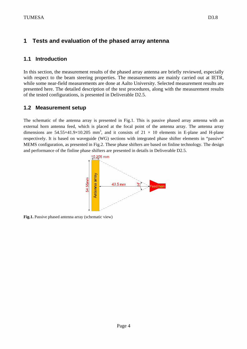
1.1 Introduction In this section, the measurement results of the phased array antenna are briefly reviewed, especially with respect to the beam steering properties. The measurements are mainly carried out at IETR, while some near-field measurements are done at Aalto University. Selected measurement results are presented here. The detailed description of the test procedures, along with the measurement results of the tested configurations, is presented in Deliverable D2.5. 1.2 Measurement setup The schematic of the antenna array is presented in Fig.1. This is passive phased array antenna with an external horn antenna feed, which is placed at the focal point of the antenna array. The antenna array dimensions are 54.55×41.9×10.205 mm3, and it consists of 21 × 10 elements in E-plane and H-plane respectively. It is based on waveguide (WG) sections with integrated phase shifter elements in “passive” MEMS configuration, as presented in Fig.2. These phase shifters are based on finline technology. The design and performance of the finline phase shifters are presented in details in Deliverable D2.5.
Fig.1. Passive phased antenna array (schematic view)
TUMESA D3.8
Page 5
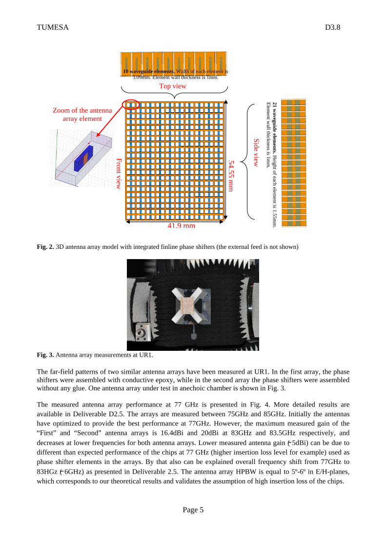
Fig. 2. 3D antenna array model with integrated finline phase shifters (the external feed is not shown)
Fig. 3. Antenna array measurements at UR1.
The far-field patterns of two similar antenna arrays have been measured at UR1. In the first array, the phase shifters were assembled with conductive epoxy, while in the second array the phase shifters were assembled without any glue. One antenna array under test in anechoic chamber is shown in Fig. 3. The measured antenna array performance at 77 GHz is presented in Fig. 4. More detailed results are available in Deliverable D2.5. The arrays are measured between 75GHz and 85GHz. Initially the antennas have optimized to provide the best performance at 77GHz. However, the maximum measured gain of the “First” and “Second” antenna arrays is 16.4dBi and 20dBi at 83GHz and 83.5GHz respectively, and decreases at lower frequencies for both antenna arrays. Lower measured antenna gain (̴ 5dBi) can be due to different than expected performance of the chips at 77 GHz (higher insertion loss level for example) used as phase shifter elements in the arrays. By that also can be explained overall frequency shift from 77GHz to 83HGz ( ̴ 6GHz) as presented in Deliverable 2.5. The antenna array HPBW is equal to 5º-6º in E/H-planes, which corresponds to our theoretical results and validates the assumption of high insertion loss of the chips.
Top view
Front view
Side view
Zoom of the antenna array element
41.9 mm
54.55m
m
10 waveguide elements. Width of each element is 3.09mm. Element wall thickness is 1mm.
21 waveguide elem
ents. Height of each elem
ent is 1.55mm
. Elem
ent wall thickness is 1m
m.
TUMESA D3.8
Page 6
First array
-90 -60 -30 0 30 60 90-60
-50
-40
-30
-20
-10
0
Nor
m G
ain
[dB
]
Angle [degree]
Co-pol Theor Co-pol Meas X-pol Theor X-pol Meas
77 GHz E-plane
-90 -60 -30 0 30 60 90-60
-50
-40
-30
-20
-10
0
Nor
m G
ain
[dB
]
Angle [degree]
Co-pol Theor Co-pol Meas X-pol Theor X-pol Meas
77 GHz H-plane
Second array
-90 -60 -30 0 30 60 90-60
-50
-40
-30
-20
-10
0
Nor
m G
ain
[dB
]
Angle [degree]
Co-pol Theor Co-pol Meas X-pol Theor X-pol Meas
77 GHz E-plane
-90 -60 -30 0 30 60 90-60
-50
-40
-30
-20
-10
0
Nor
m G
ain
[dB
]
Angle [degree]
Co-pol Theor Co-pol Meas X-pol Theor X-pol Meas
77 GHz H-plane
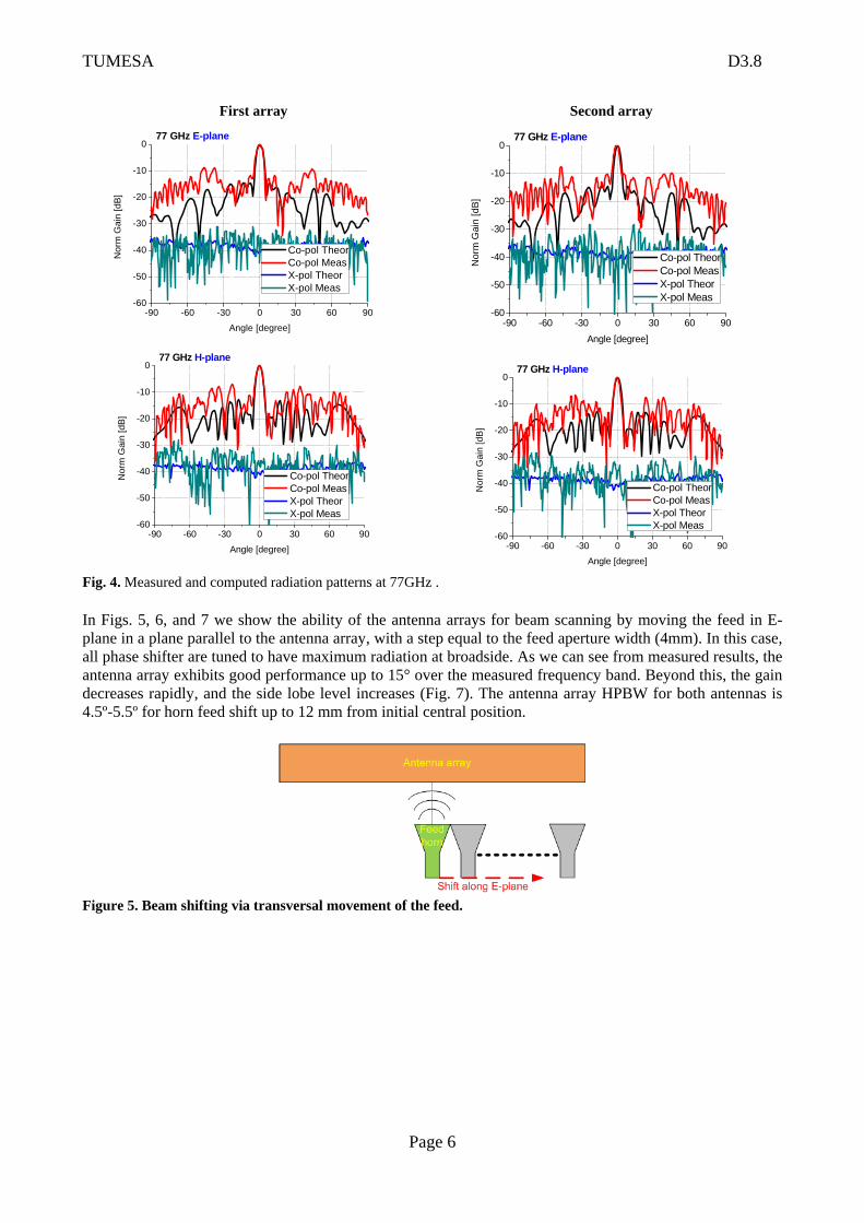
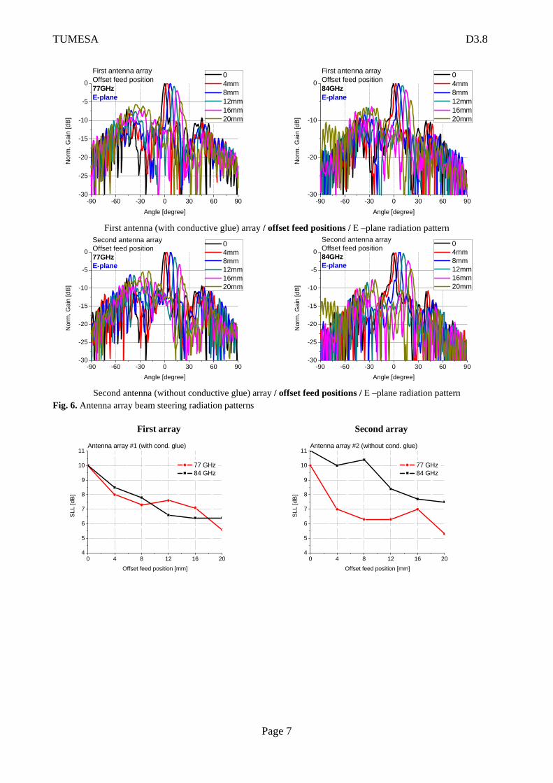
Fig. 4. Measured and computed radiation patterns at 77GHz . In Figs. 5, 6, and 7 we show the ability of the antenna arrays for beam scanning by moving the feed in E-plane in a plane parallel to the antenna array, with a step equal to the feed aperture width (4mm). In this case, all phase shifter are tuned to have maximum radiation at broadside. As we can see from measured results, the antenna array exhibits good performance up to 15° over the measured frequency band. Beyond this, the gain decreases rapidly, and the side lobe level increases (Fig. 7). The antenna array HPBW for both antennas is 4.5º-5.5º for horn feed shift up to 12 mm from initial central position.
Figure 5. Beam shifting via transversal movement of the feed.
TUMESA D3.8
Page 7
-90 -60 -30 0 30 60 90-30
-25
-20
-15
-10
-5
0
Nor
m. G
ain
[dB
]
Angle [degree]
0 4mm 8mm 12mm 16mm 20mm
First antenna array Offset feed position77GHzE-plane
-90 -60 -30 0 30 60 90-30
-20
-10
0
Nor
m. G
ain
[dB
]
Angle [degree]
0 4mm 8mm 12mm 16mm 20mm
First antenna array Offset feed position84GHzE-plane
First antenna (with conductive glue) array / offset feed positions / E –plane radiation pattern
-90 -60 -30 0 30 60 90-30
-25
-20
-15
-10
-5
0
Nor
m. G
ain
[dB]
Angle [degree]
0 4mm 8mm 12mm 16mm 20mm
Second antenna array Offset feed position77GHzE-plane
-90 -60 -30 0 30 60 90-30
-25
-20
-15
-10
-5
0
Nor
m. G
ain
[dB]
Angle [degree]
0 4mm 8mm 12mm 16mm 20mm
Second antenna array Offset feed position84GHzE-plane
Second antenna (without conductive glue) array / offset feed positions / E –plane radiation patternFig. 6. Antenna array beam steering radiation patterns
First array Second array
0 4 8 12 16 204
5
6
7
8
9
10
11
SLL
[dB
]
Offset feed position [mm]
Antenna array #1 (with cond. glue)
77 GHz 84 GHz
0 4 8 12 16 204
5
6
7
8
9
10
11
SLL
[dB
]
Offset feed position [mm]
Antenna array #2 (without cond. glue)
77 GHz 84 GHz
TUMESA D3.8
Page 8
0 4 8 12 16 204
5
6
7
8H
PBW
[deg
ree]
Offset feed position [mm]
Antenna array #1 (with cond. glue)
77 GHz 84 GHz
0 4 8 12 16 204
5
6
7
8
HP
BW [d
egre
e]
Offset feed position [mm]
Antenna array #2 (without cond. glue)
77 GHz 84 GHz
0 5 10 15 200
5
10
15
20Antenna array #1 (with cond. glue)
Gai
n [d
Bi]
Offset feed position [mm]
77 GHz 84GHz
0 5 10 15 20
0
5
10
15
20
Antenna array #2 (without cond. glue)
Gai
n [d
Bi]
Offset feed position [mm]
77 GHz 84GHz
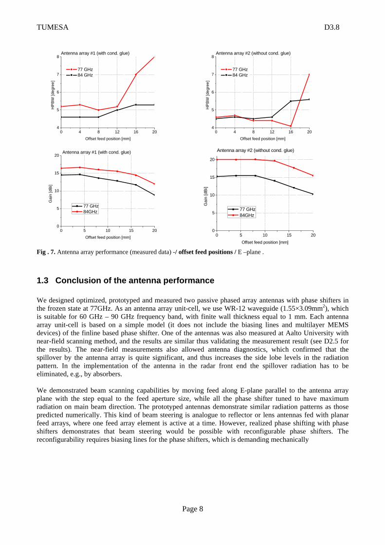
Fig . 7. Antenna array performance (measured data) -/ offset feed positions / E –plane . 1.3 Conclusion of the antenna performance We designed optimized, prototyped and measured two passive phased array antennas with phase shifters in the frozen state at 77GHz. As an antenna array unit-cell, we use WR-12 waveguide (1.55×3.09mm2), which is suitable for 60 GHz – 90 GHz frequency band, with finite wall thickness equal to 1 mm. Each antenna array unit-cell is based on a simple model (it does not include the biasing lines and multilayer MEMS devices) of the finline based phase shifter. One of the antennas was also measured at Aalto University with near-field scanning method, and the results are similar thus validating the measurement result (see D2.5 for the results). The near-field measurements also allowed antenna diagnostics, which confirmed that the spillover by the antenna array is quite significant, and thus increases the side lobe levels in the radiation pattern. In the implementation of the antenna in the radar front end the spillover radiation has to be eliminated, e.g., by absorbers. We demonstrated beam scanning capabilities by moving feed along E-plane parallel to the antenna array plane with the step equal to the feed aperture size, while all the phase shifter tuned to have maximum radiation on main beam direction. The prototyped antennas demonstrate similar radiation patterns as those predicted numerically. This kind of beam steering is analogue to reflector or lens antennas fed with planar feed arrays, where one feed array element is active at a time. However, realized phase shifting with phase shifters demonstrates that beam steering would be possible with reconfigurable phase shifters. The reconfigurability requires biasing lines for the phase shifters, which is demanding mechanically
TUMESA D3.8
Page 9
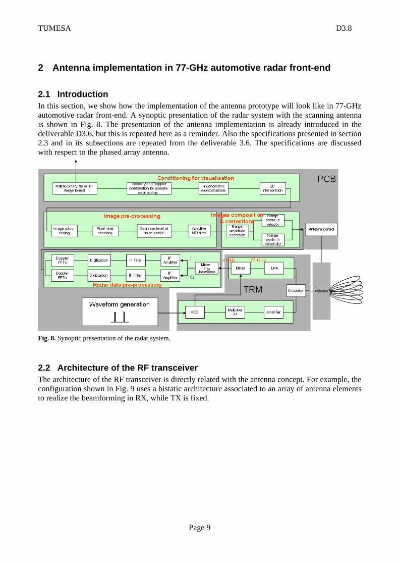
2 Antenna implementation in 77-GHz automotive radar front-end 2.1 Introduction In this section, we show how the implementation of the antenna prototype will look like in 77-GHz automotive radar front-end. A synoptic presentation of the radar system with the scanning antenna is shown in Fig. 8. The presentation of the antenna implementation is already introduced in the deliverable D3.6, but this is repeated here as a reminder. Also the specifications presented in section 2.3 and in its subsections are repeated from the deliverable 3.6. The specifications are discussed with respect to the phased array antenna.
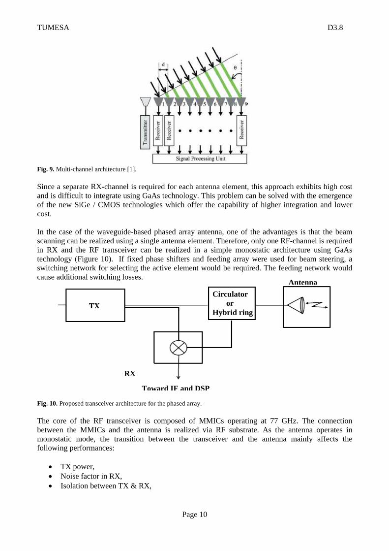
Fig. 8. Synoptic presentation of the radar system. 2.2 Architecture of the RF transceiver The architecture of the RF transceiver is directly related with the antenna concept. For example, the configuration shown in Fig. 9 uses a bistatic architecture associated to an array of antenna elements to realize the beamforming in RX, while TX is fixed.
TUMESA D3.8
Page 10
Fig. 9. Multi-channel architecture [1]. Since a separate RX-channel is required for each antenna element, this approach exhibits high cost and is difficult to integrate using GaAs technology. This problem can be solved with the emergence of the new SiGe / CMOS technologies which offer the capability of higher integration and lower cost. In the case of the waveguide-based phased array antenna, one of the advantages is that the beam scanning can be realized using a single antenna element. Therefore, only one RF-channel is required in RX and the RF transceiver can be realized in a simple monostatic architecture using GaAs technology (Figure 10). If fixed phase shifters and feeding array were used for beam steering, a switching network for selecting the active element would be required. The feeding network would cause additional switching losses.
Fig. 10. Proposed transceiver architecture for the phased array. The core of the RF transceiver is composed of MMICs operating at 77 GHz. The connection between the MMICs and the antenna is realized via RF substrate. As the antenna operates in monostatic mode, the transition between the transceiver and the antenna mainly affects the following performances:
• TX power, • Noise factor in RX, • Isolation between TX & RX,
TX
RX
Toward IF and DSP
Circulator or Hybrid ring
Antenna
TUMESA D3.8
Page 11
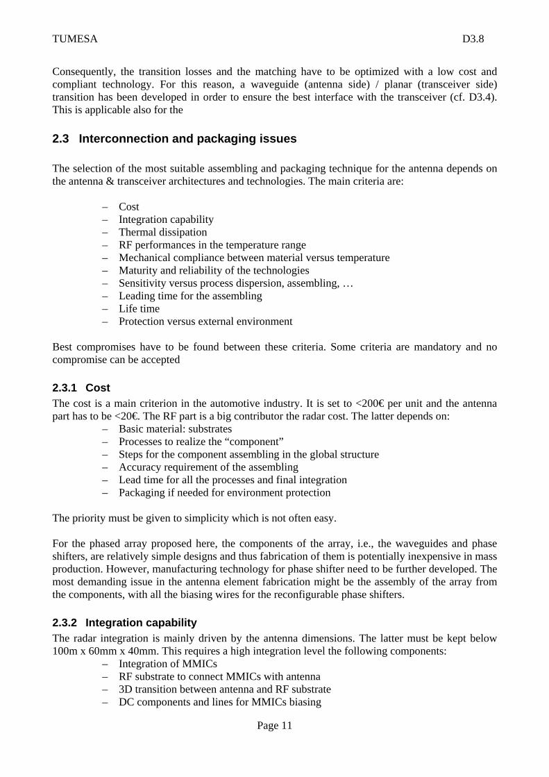
Consequently, the transition losses and the matching have to be optimized with a low cost and compliant technology. For this reason, a waveguide (antenna side) / planar (transceiver side) transition has been developed in order to ensure the best interface with the transceiver (cf. D3.4). This is applicable also for the 2.3 Interconnection and packaging issues The selection of the most suitable assembling and packaging technique for the antenna depends on the antenna & transceiver architectures and technologies. The main criteria are:
– Cost – Integration capability – Thermal dissipation – RF performances in the temperature range – Mechanical compliance between material versus temperature – Maturity and reliability of the technologies – Sensitivity versus process dispersion, assembling, … – Leading time for the assembling – Life time – Protection versus external environment
Best compromises have to be found between these criteria. Some criteria are mandatory and no compromise can be accepted 2.3.1 Cost The cost is a main criterion in the automotive industry. It is set to <200€ per unit and the antenna part has to be <20€. The RF part is a big contributor the radar cost. The latter depends on:
– Basic material: substrates – Processes to realize the “component” – Steps for the component assembling in the global structure – Accuracy requirement of the assembling – Lead time for all the processes and final integration – Packaging if needed for environment protection
The priority must be given to simplicity which is not often easy. For the phased array proposed here, the components of the array, i.e., the waveguides and phase shifters, are relatively simple designs and thus fabrication of them is potentially inexpensive in mass production. However, manufacturing technology for phase shifter need to be further developed. The most demanding issue in the antenna element fabrication might be the assembly of the array from the components, with all the biasing wires for the reconfigurable phase shifters. 2.3.2 Integration capability The radar integration is mainly driven by the antenna dimensions. The latter must be kept below 100m x 60mm x 40mm. This requires a high integration level the following components:
– Integration of MMICs – RF substrate to connect MMICs with antenna – 3D transition between antenna and RF substrate – DC components and lines for MMICs biasing
TUMESA D3.8
Page 12
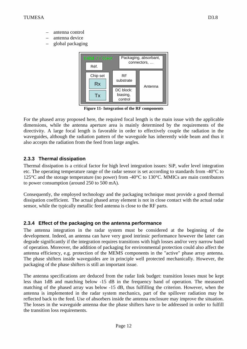
– antenna control – antenna device – global packaging
TRM 77 GHz
Chip set RFsubstrate
Antenna
Tx
RxDC block: biasing, control
Packaging, absorbant, connectors, …
Réf.
Figure 11- Integration of the RF components
For the phased array proposed here, the required focal length is the main issue with the applicable dimensions, while the antenna aperture area is mainly determined by the requirements of the directivity. A large focal length is favorable in order to effectively couple the radiation in the waveguides, although the radiation pattern of the waveguide has inherently wide beam and thus it also accepts the radiation from the feed from large angles.
2.3.3 Thermal dissipation Thermal dissipation is a critical factor for high level integration issues: SiP, wafer level integration etc. The operating temperature range of the radar sensor is set according to standards from -40°C to 125°C and the storage temperature (no power) from -40°C to 130°C. MMICs are main contributors to power consumption (around 250 to 500 mA). Consequently, the employed technology and the packaging technique must provide a good thermal dissipation coefficient. The actual phased array element is not in close contact with the actual radar sensor, while the typically metallic feed antenna is close to the RF parts.
2.3.4 Effect of the packaging on the antenna performance The antenna integration in the radar system must be considered at the beginning of the development. Indeed, an antenna can have very good intrinsic performance however the latter can degrade significantly if the integration requires transitions with high losses and/or very narrow band of operation. Moreover, the addition of packaging for environmental protection could also affect the antenna efficiency, e.g. protection of the MEMS components in the "active" phase array antenna. The phase shifters inside waveguides are in principle well protected mechanically. However, the packaging of the phase shifters is still an important issue. The antenna specifications are deduced from the radar link budget: transition losses must be kept less than 1dB and matching below -15 dB in the frequency band of operation. The measured matching of the phased array was below -15 dB, thus fulfilling the criterion. However, when the antenna is implemented in the radar system mechanics, part of the spillover radiation may be reflected back to the feed. Use of absorbers inside the antenna enclosure may improve the situation. The losses in the waveguide antenna due the phase shifters have to be addressed in order to fulfill the transition loss requirements.

TUMESA D3.8
Page 13
2.3.5 Mechanical properties Vs temperature The stacking of the different components (antenna, RF substrate, plate etc.) has to ensure good mechanical thermal expansion coefficient in the 3 axes. For example, a bad mechanical thermal expansion of the substrate in the z direction might create non flat and non regular ground continuity if the substrate is glued on a metallic plate. This effect is more problematic with large substrate dimensions, which is often the case with the antenna. With the phased array antenna the actual array is not in contact with the RF substrate, thus not affecting significantly these properties. 2.3.6 Maturity and reliability of the technology The technological choices must be coherent with the antenna concept and its integration and packaging process. In our case, GaAs technology seems to be a good choice due to its maturity, high performance and the simplicity of the transceiver architecture (1 RF-channel in RX). Due to the enormous progress in chipset technology, future automotive radars will tend to use silicon-based technologies due to its high integration capabilities (especially with array antennas) and its low cost. In the case of the phased array proposed here, there is, however, still need for technology transfer and further development of the manufacturing process from the prototyping of the phased array elements towards mass production. 2.3.7 Sensitivity versus process dispersion, assembling, … The antenna integration has to be robust versus technology, processes and assembling spread. Hence, worst cases have to be considered to analyze the antenna performance in its real environment and Monte Carlo simulations can be realized to see if the performance remains in the specified envelope. 2.3.8 Leading time for the assembling The leading time depends on the assembling and the steps required for the antenna integration within the radar system. This criterion impacts the cost of production. Thus, the priority is to reduce the assembling steps as much as possible. 2.3.9 Life time A typical radar warranty is 8000 hours at a mean speed of 37.5 km/h (300000km). 2.3.10 Environmental protection The protection of the radar components against external environment should not affect their performance. For example, the Radom and the plastic bumper must be transparent regarding the antenna radiation, electromagnetic perturbations, high frequency devices, chocks, thermal aspects, pollution etc.
3 Bibliography [1] Y. Asano, S. Ohshima, T. Harada, M. Ogawa, and K. Nishikawa, “Proposal of millimeter-wave holographic radar with antenna switching,” IEEE MTT-S International Microwave Symposium Digest, Phoenix AZ, USA, May 20- 25, 2001, vol. 2, pp. 1111–1114.