Settlement of a circular silo foundation - Fine · Determine the settlement of a circular silo...
16
Engineering manual No. 22 Updated: 02/2018 1 Settlement of a circular silo foundation Program: FEM File: Demo_manual_22.gmk The objective of this manual is to describe the solution to a circular silo foundation settlement using the Finite Element Method and the Axial Symmetry module. Task specification Determine the settlement of a circular silo foundation (thickness of 0.5 m and diameter of 20.0 m) induced by the complete filling of the silo, i.e. the surcharge kPa q 150 . Further determine the total settlement of the silo after it is subsequently emptied. The geological profile, including parameters of soils, is identical with the profile described in the previous task (chapter 21. Analysis of terrain settlement induced by strip surcharge loading). Apply the axial symmetry to this particular case. The circular silo foundation is made from a matured reinforced concrete, class C 20/25. Task specification chart – a circular silo foundation
-
Upload
trinhquynh -
Category
Documents
-
view
227 -
download
0
Transcript of Settlement of a circular silo foundation - Fine · Determine the settlement of a circular silo...

Engineering manual No. 22
Updated: 02/2018
1
Settlement of a circular silo foundation
Program: FEM
File: Demo_manual_22.gmk
The objective of this manual is to describe the solution to a circular silo foundation settlement
using the Finite Element Method and the Axial Symmetry module.
Task specification
Determine the settlement of a circular silo foundation (thickness of 0.5 m and diameter of 20.0 m)
induced by the complete filling of the silo, i.e. the surcharge kPaq 150 . Further determine the
total settlement of the silo after it is subsequently emptied. The geological profile, including
parameters of soils, is identical with the profile described in the previous task (chapter 21. Analysis of
terrain settlement induced by strip surcharge loading). Apply the axial symmetry to this particular
case. The circular silo foundation is made from a matured reinforced concrete, class C 20/25.
Task specification chart – a circular silo foundation

2
In this case, the values of the total vertical deformation, i.e. settlement mmd z, will be derived
from the Mohr-Coulomb material model only. The comparison of the other material models with
various mesh densities was carried out in the previous chapter 21. Analysis of terrain settlement
induced by strip surcharge loading.
Solution
The analysis will be performed using the GEO 5 – FEM program. The following paragraphs provide
a step by step description of the solution:
Topology: setting and modelling the problem (free points),
Construction stage 1: primary geostatic stress,
Construction stage 2: modelling and loading on beam elements, settlement analysis,
Construction stage 3: unloaded terrain surface settlement (deformation) analysis, internal forces,
Assessment of results: comparison, conclusion.
Note: To solve this task we shall represent the silo foundation made of reinforced concrete
by beam elements free of contact elements thus assuming a perfect bond between the foundation
and the soil. The issue of contact elements will be analysed in more detail in Chapter 24. Numerical
solution to a sheeting wall structure.
Topology: problem settings
We will select the “Axial symmetry” option as the Project type in the “Settings” frame. The
other data will remain the same.
“Settings” frame
Note: Axial symmetry is suitable for solving rotationally symmetric problems. This assumption
must comply both with the geometrical arrangement of the structure and the loading. The solution to
this problem – a circular silo foundation – is therefore a suitable example.

3
The solution is related to 1rad of the )(rx -radius arch. The axis of symmetry always represents
the )(rx coordinate origin. Shear components of deformation in the direction of rotation can be
disregarded. The evolution of a circumferential normal component of stress and strain (hoop stress
and strain) is also taken into consideration, in addition to the components of stress and strain in the
cross-sectional plane (for more details visit Help – F1).
In the “Interface” frame, we will first set the new world coordinates. Then we will set the
coordinates of the first point of the interface to [10, 0]. The next point of the interface (at the edges)
will be added by the program automatically.
“Interface” frame + “World coordinates” dialogue window

4
Then we will define the parameters of soils and assign them to the interface region No. 1. In this
particular case neither rigid bodies nor contact types will be considered.
“Add new soils” dialog window

5
For the mesh generation, we will first set the elements edge length to 2.0 m.
“Mesh generation” frame – Triangular mesh with the element edge length of 2.0 m
Upon examining the generated mesh, we may conclude that for a given problem the resulting
mesh is too coarse. For that reason, we will change the length of the edges of the mesh elements to
1.0 m.

6
“Mesh generation” frame – Triangular mesh with the element edge length of 1.0 m
Note: It would be reasonable to refine the density of the mesh using line refinement for the area
under the circular silo foundation that is being solved (for more details visit Help – F1). We will
describe this function in more detail in the following chapter 23. Collector lining analysis.

7
Construction stage 1: primary geostatic stress
After generating the FE mesh, we will switch over to construction stage 1 and carry out the
primary geostatic stress analysis. We will leave the analysis settings as “Standard” (for more details
visit Help – F1).
“Analysis” frame – Construction stage 1

8
Construction stage 2: modelling of and loading on beam elements
In the next step we will add construction stage 2. Then, in the “Beams” frame, we will define the
following parameters: beam location, material and concrete class, cross-section height (0.5m) and
beam end supports (for more details visit Help – F1).
“New beams” dialogue window – Construction stage 2

9
Subsequently, we will proceed to the “Beam loads” frame, where we will set the load
magnitude mkNf 100 ; we will consider it as the weight of the circular silo walls acting on the
foundation.
“New beam loads” dialogue window – loads induced by walls, acting on the circular foundation

10
Further we will set the value of the uniform continuous load to 2
150 mkNq , representing the
filling of the circular silo, acting on its bottom or the upper edge of the foundation.
“New beam loads” dialogue window – load on the circular foundation induced by filling the silo
11
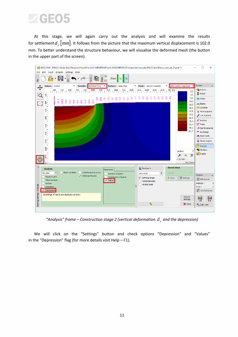
At this stage, we will again carry out the analysis and will examine the results
for settlement mmd z. It follows from the picture that the maximum vertical displacement is 102.0
mm. To better understand the structure behaviour, we will visualise the deformed mesh (the button
in the upper part of the screen).
“Analysis” frame – Construction stage 2 (vertical deformation zd and the depression)
We will click on the “Settings” button and check options “Depression” and “Values”
in the “Depression” flag (for more details visit Help – F1).
12
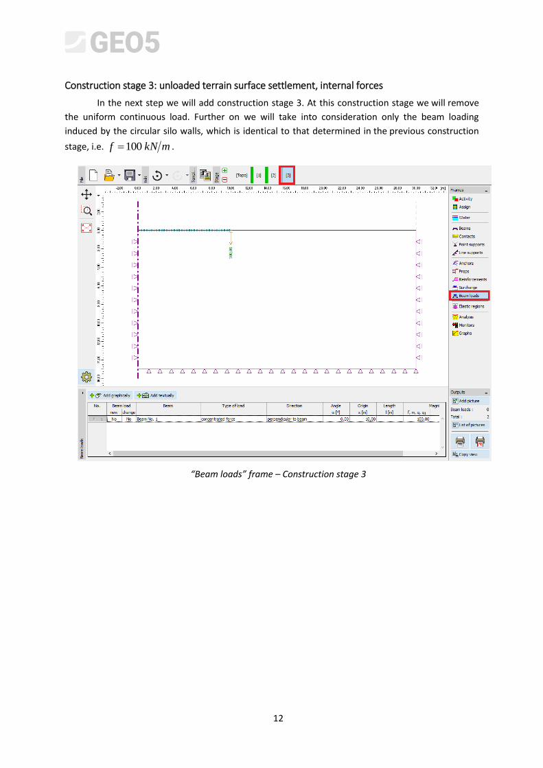
Construction stage 3: unloaded terrain surface settlement, internal forces
In the next step we will add construction stage 3. At this construction stage we will remove
the uniform continuous load. Further on we will take into consideration only the beam loading
induced by the circular silo walls, which is identical to that determined in the previous construction
stage, i.e. mkNf 100 .
“Beam loads” frame – Construction stage 3
13
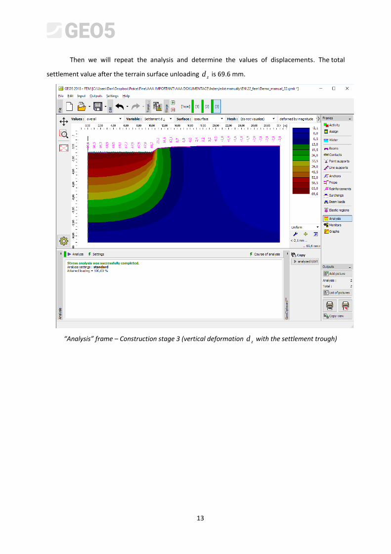
Then we will repeat the analysis and determine the values of displacements. The total
settlement value after the terrain surface unloading zd is 69.6 mm.
“Analysis” frame – Construction stage 3 (vertical deformation zd with the settlement trough)

14
Now we will examine the radial moment diagrams mkNmM r for construction stages 2 or 3
(using the “Settings” button in the “Distributions” flag) and will record the magnitudes of local
extremes in a table. The main structural reinforcement of the circular silo foundation can be
designed and assessed for these values in an arbitrary static program (e.g. FIN EC – CONCRETE 2D).
“Analysis frame – Construction stage 2 (variation of radial momentrM )
15
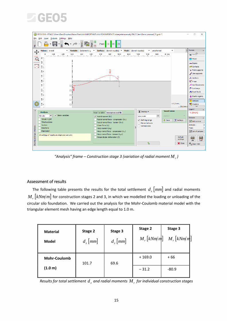
“Analysis“ frame – Construction stage 3 (variation of radial momentrM )
Assessment of results
The following table presents the results for the total settlement mmd z and radial moments
mkNmM r for construction stages 2 and 3, in which we modelled the loading or unloading of the
circular silo foundation. We carried out the analysis for the Mohr-Coulomb material model with the
triangular element mesh having an edge length equal to 1.0 m.
Material
Model
Stage 2
mmd z
Stage 3
mmd z
Stage 2
mkNmM r
Stage 3
mkNmM r
Mohr-Coulomb
(1.0 m) 101.7 69.6
+ 169.0 + 66
– 31.2 -80.9
Results for total settlement zd and radial moments
rM for individual construction stages

16
Conclusion
Several following conclusions can be drawn from the results for the quantities being examined:
When the silo is full (as a result of the action of a uniform continuous load), a positive bending moment prevails along the beam length, where its bottom fibres are stretched.
After emptying the silo (as a result of subsequent unloading), the circular foundation is loaded only by the silo walls. A negative bending moment prevails along the beam length, where its upper fibres are stretched.