Session 23 Tom Andres - Florida Department of … · Session 23 FDOT Central Office Structures. 1...
26
Noisewalls – Struct. / QPL (Complement Rds.) Topic Description Noise barrier wall design related discussions. Speaker Biography BSCE University of Florida 20 years experience with the Florida Department of Transportation. Currently Area Engineer for Districts 4, 7 and Turnpike. Tom Andres Session 23 FDOT Central Office Structures
Transcript of Session 23 Tom Andres - Florida Department of … · Session 23 FDOT Central Office Structures. 1...
Noisewalls – Struct. / QPL (Complement Rds.)
Topic Description
Noise barrier wall design related discussions.
Speaker Biography
BSCE University of Florida20 years experience with the Florida Department of Transportation. Currently Area Engineer for Districts 4, 7 and Turnpike.
Tom Andres
Session 23
FDOT Central Office Structures
1
Designing Noise Barriers
Noise Wall FDOT References
• PD&E Manual Chapter 17 http://www.dot.state.fl.us/emo/pubs/pdeman/updated/PT
2CH17_10-6-03.pdf
• PPM Chapter 32http://www.dot.state.fl.us/rddesign/PPM%20Manual/20
06/Volume%201/ZChap%2032.pdf
• Appendix B, Soils and Foundations Handbook
http://www.dot.state.fl.us/structures/Manuals/SFH.pdf
2
Noise Wall FDOT References (cont.)
• Proprietary Noise Wall Acceptance Criteria – Structures Manual Volume 6, Chapter 2
http://www.dot.state.fl.us/structures/StructuresManual/CurrentRelease/FDOTBridgeManual.htm
• Precast & Traffic Railing Design Standardshttp://www.dot.state.fl.us/rddesign/rd/RTDS/06/2006_Standar
ds_5k.htm
• Instructions for Design Standards –Structures Manual Volume 3
http://www.dot.state.fl.us/structures/StructuresManual/CurrentRelease/instructionalStandards.pdf
Noise Wall FDOT References (cont.)
• Sound Barrier Specification Section 534http://www.dot.state.fl.us/specificationsoffice/July06W
B/5340000SS.pdf
• MicroStation cell, 05200 Sound Barrier Data Table
• QPL Approved Proprietary Noise Wallshttp://www.dot.state.fl.us/specificationsoffice/QPLindex
.htm

3
Noise Barrier Design Phase Objective
ReassessmentAs Required
Addendum• Noise Study Report
• Contract Documents– Structure Plans– Noise Barrier Control Drawings– Traffic Control & Roadway Plans as
Necessary– Specifications
Noise Barrier Design Phase
• Special Designs
• General Design Process• Utilizing the FDOT Design Standards
• Other Design Related Issues

4
1. Review the noise study report
General Design Process
Preliminary Location
Determine Constraints
Based on ConstraintsFinalize Location and Type
Provide Structural Design
2. Create preliminary noise barrier control drawings
3. Stake out the noise barrier in the field and determine conflicts with overhead/ underground utilities, drainage structures
4. Select noise barrier types
5. Finalize noise barrier control drawings
6. Begin the geotechnical investigation
7. Design noise barrier
Stake Out the Noise Barrier in the Field and Determine Conflicts with Overhead / Underground Utilities, Drainage Structures
5
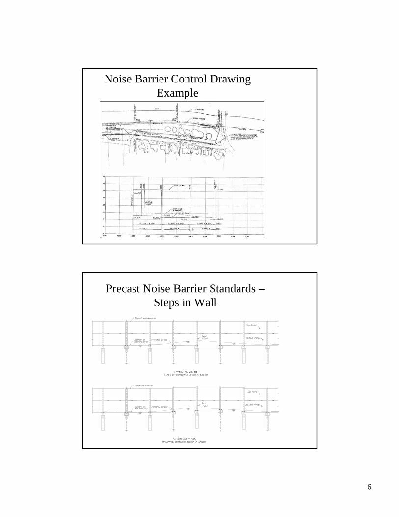
Noise Barrier Control Drawings
• Plan & elevation depicting noise barrier alignments (horizontal and vertical)
• Noise barrier limits• Location of existing utilities• Location of graphics
• Location of fire-access openings
• Location of soil borings • Location and size of drainage openings
• Lengthen noise barrier to eliminate special panel sizes on either end
Noise Barrier Control Drawings (cont.)
6
Noise Barrier Control Drawing Example
Precast Noise Barrier Standards –Steps in Wall
7
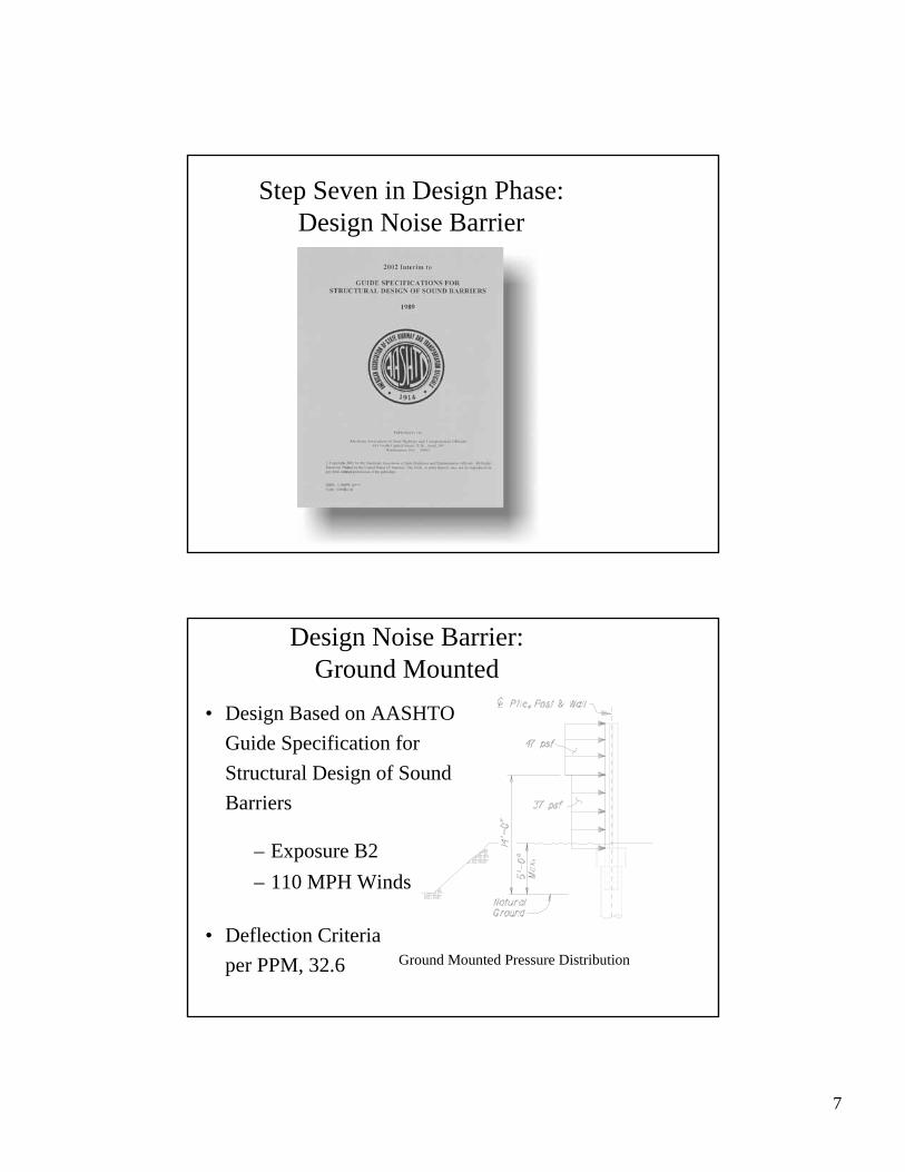
Step Seven in Design Phase:Design Noise Barrier
Design Noise Barrier: Ground Mounted
• Design Based on AASHTO Guide Specification for Structural Design of Sound Barriers
Ground Mounted Pressure Distribution
– Exposure B2– 110 MPH Winds
• Deflection Criteria per PPM, 32.6

8
Deflection Criteria per PPM, 32.6: Ground Mounted
• The Total Deflection @ Top of Wall < 1/50th of the wall height or 5 inches.
• Delta Head of Pile< 1 inch.
Deflection Criteria per PPM, 32.6:Ground Mounted Panels
• For panels, the maximum deflection due to service wind load shall not exceed the lesser of 1/180th of the post spacing or 1½ inch (deflection measured relative to posts).
9
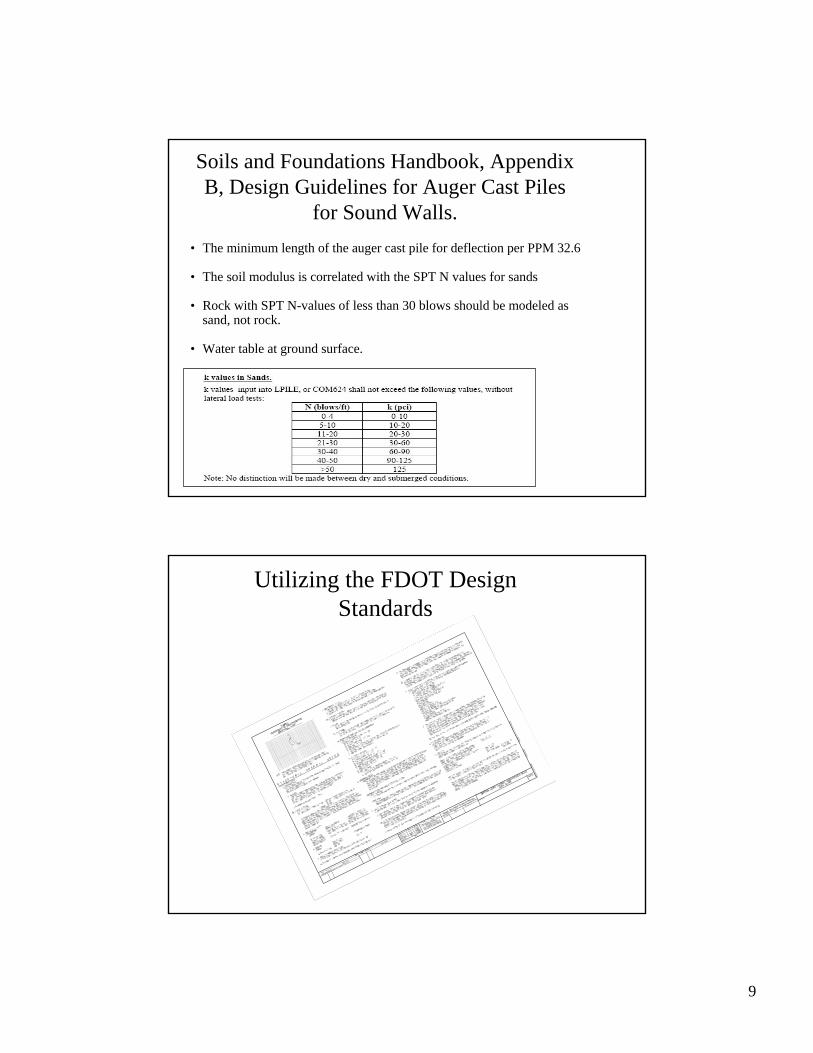
Soils and Foundations Handbook, Appendix B, Design Guidelines for Auger Cast Piles
for Sound Walls.• The minimum length of the auger cast pile for deflection per PPM 32.6
• The soil modulus is correlated with the SPT N values for sands
• Rock with SPT N-values of less than 30 blows should be modeled as sand, not rock.
• Water table at ground surface.
Utilizing the FDOT Design Standards

10
Precast Noise Barrier Standards –Ground Mounted
Instructional Sheet – Volume 3 Structures Manualhttp://www.dot.state.fl.us/structures/StructuresManual/CurrentRelease/instructionalStandard
s.pdf
Design Standards
General Notes 5200
Texture Options (8 Options for Both Posts and Panel) 5201
Flush Panel and Posts 5202
Recessed Mounted Panel and Posts 5203
Access and Drainage Details 5204
Pile and Post Details (5 Contractor Options) 5205
Pile and Post Reinforcement Table 5206
Structure Cells
Project Aesthetic Requirements MicroStation cell, 05200 Sound Barrier Data Table
Graphics (Pelican, Gull, Ibis etc.) (Examples) MicroStation cell table, SoundBarrier Graphics
Precast Noise Barrier Standards –Ground Mounted – Recessed Panel
Recessed PanelAllows Textures on Both Sides of Noise Barrier
11
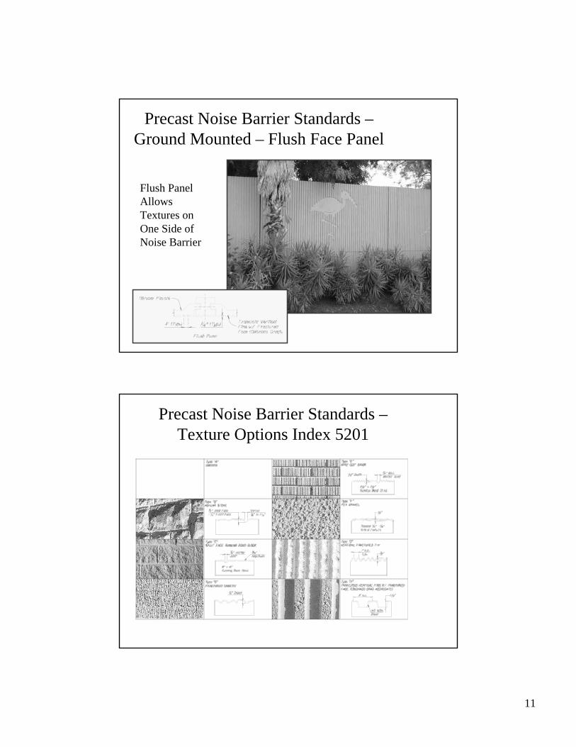
Precast Noise Barrier Standards –Ground Mounted – Flush Face Panel
Flush PanelAllows Textures on One Side of Noise Barrier
Precast Noise Barrier Standards –Texture Options Index 5201

12
Precast Noise Barrier Standards –Ground Mounted
• Approval of Proprietary Panels or Systems
– QPL Acceptance Criteria Structures Manual, Volume 6
– Proprietary Panels Detailed to fit Standard Posts Spaced at 10’ or 20’
– QPL Approved Systems Available on Specifications Website
• Proprietary Panels meeting the Aesthetics of the Project Listed in Plans (MicroStation cell, 05200 Sound Barrier Data Table)
(MicroStation cell, 05200 Sound Barrier Data Table
13
Precast Noise Barrier Standards –QPL Vendor Drawings
http://www.dot.state.fl.us/specificationsoffice/QPLindex.htm
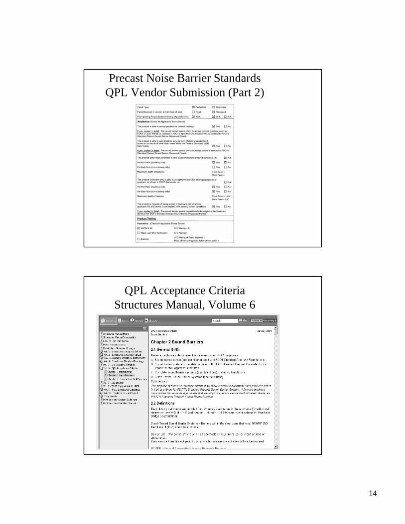
Precast Noise Barrier Standards QPL Vendor Submission (Part 1)
14
Precast Noise Barrier StandardsQPL Vendor Submission (Part 2)
QPL Acceptance CriteriaStructures Manual, Volume 6

15
Precast Noise Barrier Standards –MicroStation cell table, Sound Barrier Graphics
Precast Noise Barrier Standards –Graphic Possibilities
16
Sometimes The Precast Standard Noise Barriers Or Crash Tested Standard Noise Barriers Do Not Apply
Special Designs
Like trying to hammer a square peg into a round hole!
Ground Mounted –Masonry/CIP Noise Barriers
• Masonry Noise Barriers Or CIP Noise Barriers May Be Justified On Projects:
– with short noise barriers (12 to 14 feet high maximum)
– where construction access is difficult
– where quantities are not large enough to justify precast noise barriers
– where underground or overhead utility restrict precast noise barriers
17
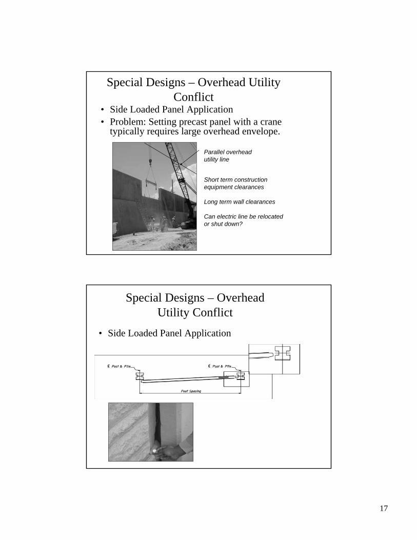
Special Designs – Overhead Utility Conflict
• Problem: Setting precast panel with a crane typically requires large overhead envelope.
Parallel overheadutility line
Short term construction equipment clearances
Long term wall clearances
Can electric line be relocated or shut down?
• Side Loaded Panel Application
Special Designs – Overhead Utility Conflict
• Side Loaded Panel Application
18
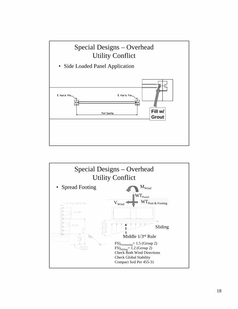
Special Designs – Overhead Utility Conflict
Fill w/Grout
• Side Loaded Panel Application
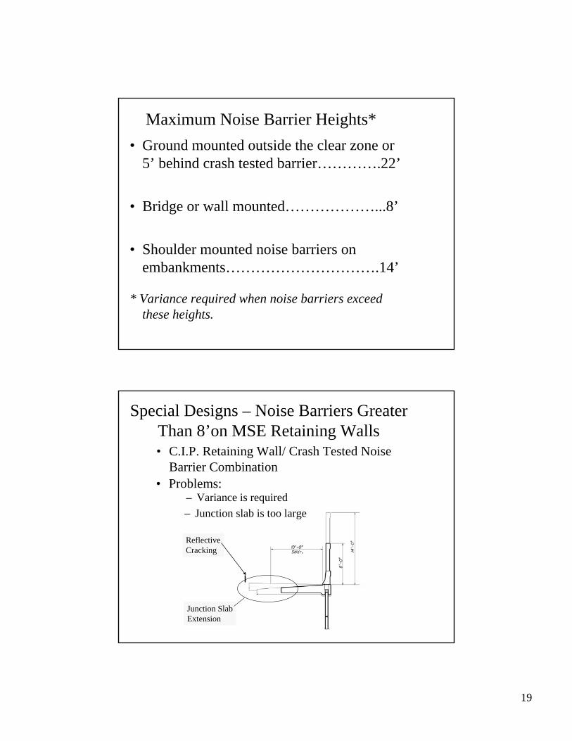
Special Designs – Overhead Utility Conflict
FS)Overturning= 1.5 (Group 2)FS)Sliding= 1.2 (Group 2)Check Both Wind DirectionsCheck Global StabilityCompact Soil Per 455-31
Sliding
MWind
VWind
WTPanelWTPost & Footing
Middle 1/3rd Rule
• Spread Footing
19
Maximum Noise Barrier Heights*• Ground mounted outside the clear zone or
5’ behind crash tested barrier………….22’
• Bridge or wall mounted………………...8’
• Shoulder mounted noise barriers on embankments………………………….14’
* Variance required when noise barriers exceed these heights.
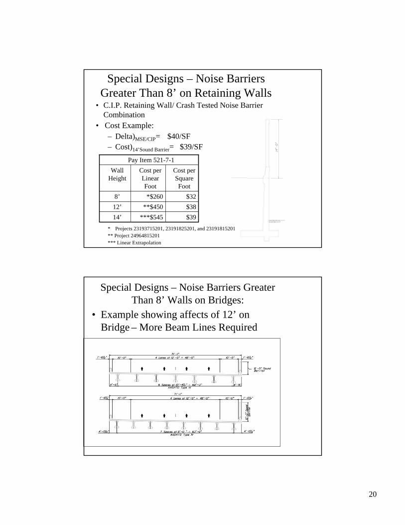
Junction SlabExtension
ReflectiveCracking
Special Designs – Noise Barriers Greater Than 8’on MSE Retaining Walls
• Problems: – Variance is required– Junction slab is too large
• C.I.P. Retaining Wall/ Crash Tested Noise Barrier Combination
20
• Cost Example:– Delta)MSE/CIP= $40/SF– Cost)14’Sound Barrier= $39/SF
* Projects 23193715201, 23191825201, and 23191815201** Project 24964815201*** Linear Extrapolation
Special Designs – Noise Barriers Greater Than 8’ on Retaining Walls
$39***$54514’$38**$45012’$32*$2608’
Cost per Square Foot
Cost per Linear Foot
Wall Height
Pay Item 521-7-1
• C.I.P. Retaining Wall/ Crash Tested Noise Barrier Combination
• Example showing affects of 12’ on Bridge – More Beam Lines Required
Special Designs – Noise Barriers Greater Than 8’ Walls on Bridges:
21
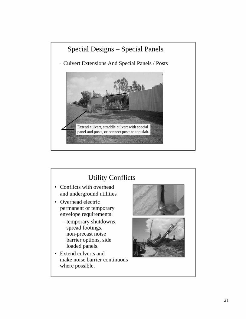
Special Designs – Special Panels
Extend culvert, straddle culvert with specialpanel and posts, or connect posts to top slab.
• Culvert Extensions And Special Panels / Posts
Utility Conflicts• Conflicts with overhead
and underground utilities• Overhead electric
permanent or temporary envelope requirements:– temporary shutdowns,
spread footings, non-precast noise barrier options, side loaded panels.
• Extend culverts and make noise barrier continuous where possible.

22
Other Design Related Issues:• Back-Of-Noise Barrier Issues• Anti-Graffiti Coating• Drainage Openings• Fire Access Openings• Roadway Items
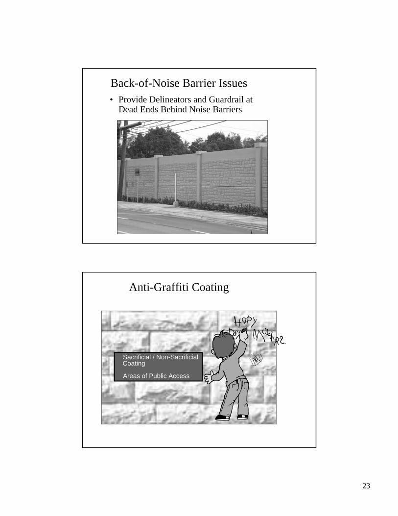
Back-of-Noise Barrier Issues
• Design/ Construction PIO Coordination With Homeowners
• Consider Eliminating Alleyway By Removing L/A Fence And Extending Property Fence
• Temporary Fencing
23
• Provide Delineators and Guardrail at Dead Ends Behind Noise Barriers
Back-of-Noise Barrier Issues
Anti-Graffiti Coating
• Sacrificial / Non-Sacrificial Coating
• Areas of Public Access
24
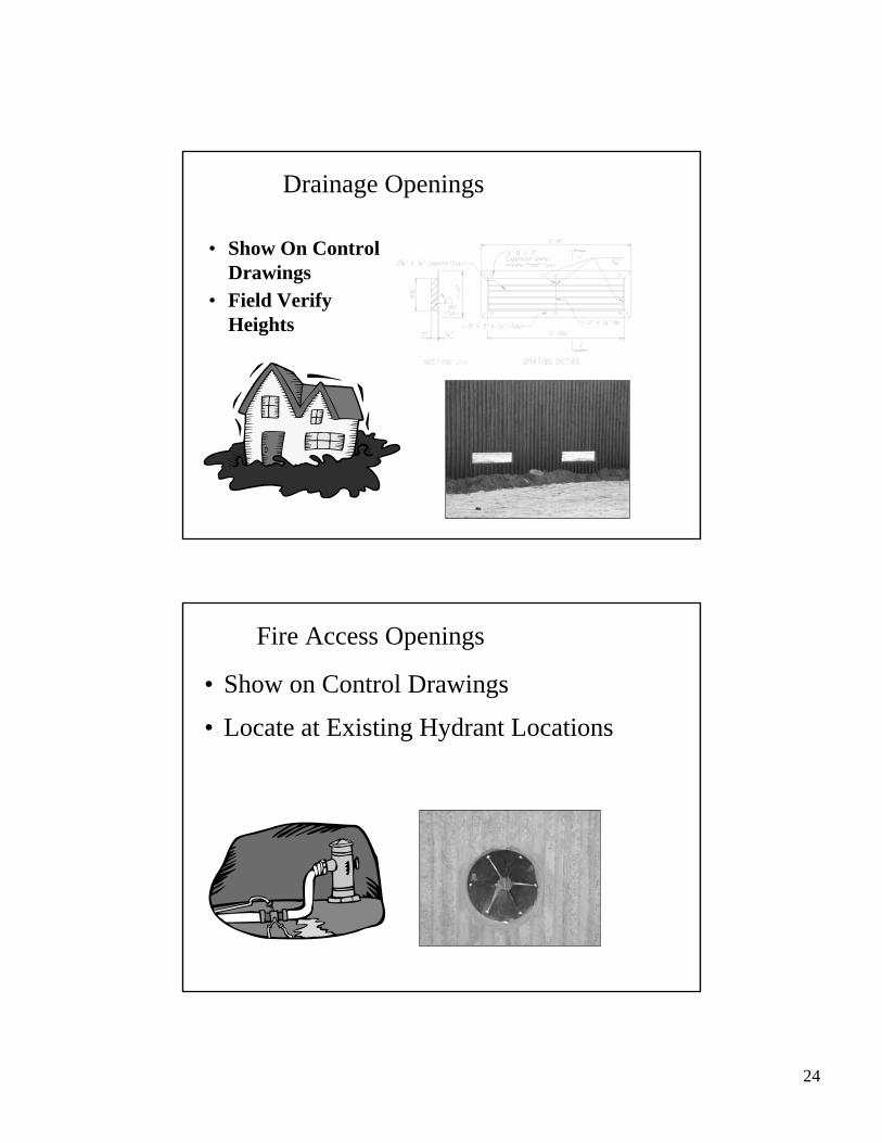
Drainage Openings
• Show On Control Drawings
• Field Verify Heights
Fire Access Openings
• Show on Control Drawings
• Locate at Existing Hydrant Locations
25
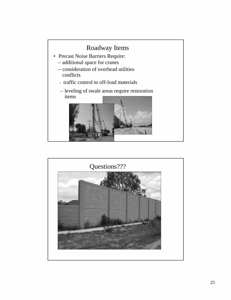
Roadway Items
– leveling of swale areas require restoration items
– consideration of overhead utilities conflicts
– traffic control to off-load materials
– additional space for cranes• Precast Noise Barriers Require:
Questions???